Embed Size (px)
Citation preview

C14
oOFFICE OF NAVAL RESEARCH
ICONTRACT NO. N00014-86-K-0772
TECHNICAL REPORT NO. 33
The Effect of Deformation History onThe Morphology and Properties of Blends of
Polycarbonate and a Thermotropic Liquid Crystalline Polymers
by
A. Kohli, N. Chung, and R. A. Weiss
Liquid Crystalline Polymer Research CenterUniversity of Connecticut
Storrs, CT 06269-3136
D7'Prepared for Publication DT:C
in
Polymer Engineering and Science
January 11, 1989 H
REPRODUCTION IN WHOLE OR IN PART IS PERMITTED FOR ANYPURPOSE OF THE UNITED STATES GOVERNMENT.
THIS DOCUMENT HAS BEEN APPROVED FOR PUBLIC RELEASEAND SALE; ITS DISTRIBUTION IS UNLIMITED.
89 1 25087

REPORT DOCUMENTATION PAGE-'d ~~ ~ ~ ~ I aApaisa1,.1 C(i5I.aIO?
unclassified Nn. i-CUltil CLA 1.I.CA11oN AVjT4OLsIT 3 O1SIAaiUhOf1AVA1LA&'UIV Of 1(?OtI
2. OCLAS.UCT.ONOO*GAAOtSG$CrEuLEDistribution Unlimited
4 P(MAMaN OAGAWCATIOf A(PORT NvMjIR4SI S. MONiOAiqNG OAGAmQIATION AIPORI NVaM*IAW
Technical Report No.33Ue. "MIW Of PUFORMING OAGMh2JAT.0N 6o. 01511 SYMIOL 76 NAME Of MONIOMING ORGANSLJAr0oN
University of Connecticut ________ Office of Naval Research1g. £001155 (C~fy. State. ind IWCode) 7b £009155 Co)'. Wtte and ZIP Code)
Storrs, CT 06268 Arlington, VA 22217
Ua. NAME Of fUNO.,04P50O1P4. It OFFICE SVMIOL I PROCUREMENT iNSTRuMINiT iO1NTdCATOk NUMIEROAGAMoZATiON (W, appkaoig
JONR N00014-86-K-0772k. AOOA1S U(Cit. Stile. aned 11P Code) 10 SOURCE 0f FuttoING PIUMIERS
800 North Quincy Avenue PROGRAM PROJECT A$ *OAK UN,!ELEMENT NOO. No. No. ACCIS11Otd NO
Arlington, VA 22217 TS
93 E 7311 nc~, SeCuvaty C1a.11W.N.VIThe Effect of Deformation History on the Norpo ogyand Propertieucaied
of Blends of Polycarbonate and a Therumotropic Liq4iid Crystalline Polyvin12. PERSONAL AUTkO(%3
lw, lw'T u at(Poxv 130 TimE (OA1 Oj 14,6,%T( of A(POAt rtj. Month. Day) 5-PAGE COUhiFlo __MOI 8 1989-i-11
16 SUPP Ej%4t.T1AAV NOYATmON
Submitted to Polymer Engineering an d Sci4 n (LCPRC Publication No. Rsn:1COSAfT C(00(1to SuMi ElMS (Conewe... on feve'se of recess'm # nsfy by " k~t
let GROUP Sl GROUP Liquid Crystalline Polymers, ;dPolymer Blends* ~)M
1,$ Aft Rf Coan.. on r.eoe d noewa a'~nd o" Air le ^W~"ec
The addition of an imescble LCP phase improves the melt processability of a hosthermoplastic polymer. In addition, by mploying a suitable deformation history, the LCPphase may be elongated and oriented such that a microfibrillar morphology can be retainsdin the solid state. This has important ramifications for the develo-st ofself-reinforcing polymer blends to compete with conventional. inorganic fiber-reinforosdpolymers. Shear flows are generally ineffective at developing these morpbologies,bmt flowsthat incorporate an extensional region, such as the converging flow found at the entranceto a capillary or die can produce an elongated LCP phase. Simple extensional flows, suchas mlt drawing , are most effective at producing LcP sicrofibrils, and their efficiencyincreases with increasing draw ratio. The moduli of highly drawn blends were wellapproximated by a compsite analogy of long uniauially oriented LCI fibers in a PCmatrix. .
JO 041R'UUT*OI. AATUY Of ASRACT it AaSTRACT SICUijRy CLASSF.CATIONWUWCLASWEj0UNti *" 0 SAME AS RIPT COTIC US$ERS Unclassified
)24 NOAM4 0f RESPO"SI AO9VIDUAL )it TELEP'iONtf ndd Area Code 112c. 09(1 SYMBOLDr. KennethJ. Wynne (202) 696-4410 ONR
00 FORM 14 73, sa MAR ,8FA?t"on may b WE.Alvnd ahavst,6. _SECulite CLASSIFICArWoN OF tM' PAGE1(9AUosedd~~ l~ O~~eo **aft it

S j -
S
THE EFFECT OF DEFORMATION HISTORY ONTHE MORPHOLOGY AND PROPERTIES OF BLENDS OF
POLYCARBONATE AND A THERMOTROPIC LIQUID CRYSTALLINE POLYMERS
BY
A. KOHLI*, N. CHUNG, AND R. A. WEISS**
DEPARTMENT OF CHEMICAL ENGINEERING ANDLIQUID CRYSTALLINE POLYMER RESEARCH CENTER
UNIVERSITY OF CONNECTICUTSTORRS, CT 06269-3136
* Current Address: IBM Corporation1701 North StreetEndicott, NY 13760
** To whom correspondence should be sent.
,I
"I _ ___ n m

INTRQDUCTION
Interest in thermotropic liquid crystalline polymers (LCP)has grown in recent years due to their inherently high stiffnessand strength, high use temperatures, excellent chemicalresistance, low melt viscosity and low coefficient of expansion.However, despite extensive research and development, as well asseveral recent commorcalzations, LCP* currently haverelatively few established commercial markets. The materialstend to be expensive due primarily to high monomer costs. As aresult, the developing applications are relatively low volumeones where the LCP's enjoy clear-cut advantages over the moreconventional materials. For example, LCP's have realised theirgreatest success not in applications requiring high modulus andstrong materials, but rather in the production of intricatemoldings where the ability to fill the mold and dimensionalstability of the part are the crucial specifications.
Blending LCP's with other, less expensive thermoplasticsoffers the possibility for exploiting many of their desirablecharacteristics, but at a reduced material cost. It is notsurprising, therefore, that a growing interest in LCP/polymerblends has developed in recent years (1). The work of a numberof laboratories has been directed at developing compositions inwhich a discrete LCP phase functions both as a processing aid andas a solid-state reinforcement (2-10). At elevated temperature,the melt viscosity i8 lowered by the presence of an LCP dispersedphase. During processing of the blend, it is possible to deformand orient the LCP phase such that the solidified compoundcontains a mLcrofibrLllar LCP phase. The morphology andproperties of such blends are similar in many respects to moreconventional short-fiber reinforced plastics. As such,LWP/polymer blends may be effective for improving the dimensionalstability of thermoplastic films or moldings, or they may becompetitive with glass fLber-reinforced plastics in applicationswhere processabillty and low density are key requirements.
Previous work in our laboratory (5) has demonstrated thefeasibility of using the addition of an LCP to a thermoplastic inorder to both improve processability and to form in situ areinforcing phase. In that study, it was concluded thatorientation and deformation of the LCP dispersed phase wasnecessary for both effects. The reinforcing phase consisted ofLCP microfibrlls with diameters and aspect ratios of the order ofpm's and 100, respectively. The objective of the researchdescribed herein was to assess the effect of deformation historyon the morphology and properties of LCP/polymer blends. 5eSpecifically, the relative importance of extensional and simple 1]shear flows on the development of a mLcrofLbrillar LCP domain [structure was investigated.
gXPBRIXE-TAL
The thermotropLc liquid crystalline polymer, Vectra RD500, es
maCPETEDI. Z':eI I

was kindly provided by Dr. Larry F. Charbonneau of Hoechst-Celanese Corporation. It was a terpolymer comprised of 52 molo%4-hydroxybenzoic acid (HBA), 28 mole% 6-hydroxy-2-naphthoic acid(mha) 10 molo% terephthalic, acid, and 10 moler hydroquinone.The inherent viscosity at 25 C for 0.1 wtt concentration in a limixture of pentafluorophenols hexafluoropropanol was 3.08 (11).The polycarbonate (PC) used had a number average molecular weightof 16,000 and weight average molecular weight of 34,000 asdetermined by gel permeation chromatography.
Blends of LCP and PC ranging in composition from 5 - 80 vt%WCP were prepared by melt blending at 270"C with a CustomScientific Instruments (CSI) Kax-mixing extruder. Beforeblending, the neat polymers were dried in a vacuum oven at 1150Cfor at least 24 hours. The CSI extruder was also-used with atake up device to prepare melt drawn fibers.
Transition temperatures of the blends as well as the neatpolymers were measured with a Perkin-Elmer DSC 7 differentialscanning calorimeter equipped with a mechanical coolingaccessory, a TAC 7 thermal analysis instrument controller, and aPE 7500 professional computer. In order to remove any previousthermal histories, all the samples were initially scanned from30*C to 290*C at a heating rate of 20°C/minute and then quenchedas rapidly as possible in the instrument. All subsequent heatingand cooling scans were made at a rate of 20*C/min. Samples of9-13 mg were encapsulated in aluminum pans and the measurementswere made under a nitrogen atmosphere.
Shear viscosity measurements were made with a RheometricsSystem 4 mechanical spectrometer using a cone and plate geometry.The cone had an angle of 0.1 radians and a diameter of 25 m.The shear rate range covered was from 0.01 to 10.0 * . Theexperiments were conducted in a gas convection environmentalchamber at 270"C. For higher shear rates, viscosity measurementswere made with an Instron capillary viscometer. All experimentswere done at 270*C and at least three experiments on freshsamples were made for each composition. A capillary with L/D -40 and D - 1.27 mm was used. Entrance pressure corrections wereneglected, but the Rabinowitsch correction for non-Newtonianbehavior was applied. For the morphology studies, capillarieswith L/D - 20 and 10 were also used.
Scanning electron micrographs of fracture surfaces of theblends were obtained with an AMR model 1200 scanning electronmicroscope (SEX). The samples were fractured under tension inliquid nitrogen and sputter coated with a 10 n thick layer ofgold in order to provide a conductive path. In order to preservethe structure of the melt formed during the rheologicalmeasurements, the samples were quenched in ice water. In thecase of the capillary experiments, this simply required extrusioninto ice water. For the cone and plate experiments, it requiredquickly removing the fixtures after stopping the flow and placingthe cone and plate sandwich into ice water. This generally tookless than one minute after the cessation of shearing.

Dynamic mechanical measurements were made with a PolymerLaboratories Dynamic Mechanical Thermal Analyzer (DMTA) using thetensile mode. Bar specimens, about 5 m x 1 mm x 2 mm, were cutform compression molded films and fiber specimens, about 0.1 mdiameter, were used for the drawn samples. All measurements weremade with a frequency of I Hz and a strain amplitude of 0.3%.
pESULTS AND DISCUSSION
The D6C thermograms of the blends as well as the neatpolymers are shown in Fig. 1. The glass transition temperaturesof the LCP and the PC were 101C and 147*C, respectively, and the
crystalline to nematic transition (K -: N) for the LCP was about236*C. The nematic nature of the LCP mesophase was confirmed bya threaded-Schileren texture observed by polarized optical
microscopy. The nematic to isotropic transition was not observedbefore decomposition of the LCP occurred.
The composition dependence of the transitions is shown in
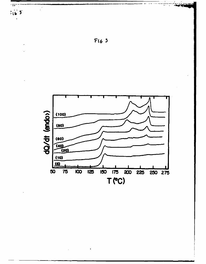
Fig. 2 for two different thermal hLstories: (11 after quenchingrapidly from 290"C and (2) after cooling at 20 C/mnn from 2700C.The thermal data are summarized in Tables 1-3. The cooling datashowed a considerable super-cooling of the N -> K transition andthe two Tg's. The X -> N transition of the LCP remained constantin the blends at the same temperature as for the pure LCP.Although the enthalpy change was dependent on the sample'sthermal history, the position of the endotherm was not. Theenthalpy of the N -> K transition increased when the slowercooling rate was used and the effect was greater at the lower LCPconcentrations. The Tg(PC) was relatively unaffected by thermalhistory of the blend. Tg(LCP), however, increased when thecooling rate was lowered. Both Tg's were slightly compositiondependent, though it was not clear whether this was due to somemiscibility or to phase size. Empirical fits of the Fox equation(12) to the Tg-composition data yielded an estimate of about 2%miscibility of the LCP in PC. The effect of annealing the blendsat 1450C on the transitions is shown in Fig. 3. The K -> Ntransition at 236*C became narrower and at least two otherendothermic events were observed, a lower temperature peak near200*C and a shoulder on the low temperature side of the upperendothermic peak. The latter was most noticeable in the pureLCP. Although the morphologies associated with the varioustransitions were not identified, these observations wereconsistent with that of a fast and a slow crystallization processreported for NBB/HMA copolymers (13).
The viscosity versus shear rate data at 270"C for thestarting materials and the blends are given in Fig. 4. In allcases, over the entire shear rate range studied, the meltviscosity was lowered by the addition of the LCP. The overlap ofthe viscosity data obtained from the cone and plate rheometer andthe capillary viscometer was poor. In general, the viscositiesdetermined from the capillary at low shear rates were higher thanthose measured with the cone and plate for high shear rates.

This was not too surprising since as will be shown below theshape and size of the dispersed phase was dependent not only onthe rate of deformation, but also on the instrument used tomeasure the viscosity. Although both Instruments yield a simpleshear flow field, the simple shear flow In th.e capillary ispreceded by a region of partial extensional flow at the capillaryentrance. This had a siqnificant effect on the dispersed phasemorphology.
The capillary viscometer data in Fig. 4 were consistent withother capillary studies (3-10) that also showed that relativelylow concentrations of LCP dramatically lowered the meltviscosities of thermoplastics. This effect Is clearly shownIInFig. 5 in which the melt viscosity at a shear rate of 150 a- isplotted against the blend composition. The melt viscosities ofthe blend decreased monotonically with increasing LCP content.For example, the addition of 5% and 10% LCP to PC lowered themelt Viscosity by 54% and 75%, respectively. Over the entirerange of composition the viscosity changed by nearly two ordersof magnitude.
The data for the cone and plate geometry also showed alowering of the viscosity by the addition of the LCP. Thisagreed with the results of Blizard and Baird (6), but wereinconsistent with those of Weiss et al. (5). In the latterstudy, the authors found that for steady shear flows withoutpre-extension, the addition of an LCP phase in a polystyrene meltincreased the melt viscosity. Microscopic evaluation of thoseblends revealed that the dispersed LCP phase was not deformed bythe shear flow. They concluded that it was necessary to deformthe dispersed phase in order to attain a lowering of theviscosity, and they also concluded that an extensional componentof stress was necessary for deforming the LCP phase. Thosefindings were consistent with fluid dynamic theories that predicta viscosity increase for flows in which the dispersed phase isnot deformed (13). The reason for the different results reportedhere is not understood and is the subject of current studies inour laboratory.
The viscosity curves for the blends containing up to 20% LCPreflected the viscosity-shear rate characteristics of the PC. Atlow shear rates, the curves were Newtonian# though shear thinningwas observed at the higher shear rates. The magnitude of theshear thinning increased and the shear rate for the onset ofshear thinning decreased with increasing WZP concentration. Theflow curves for the higher LCP compositions ware more typical ofthat of the pure ICP in that no clear Newtonian region wasobserved. Based on the SEX micrographs of the blendmorphologies, Fig. 6, it appeared that phase inversion occurredbetween 40 - 60% (Vt) LCP. Below 40% IC, the morphologyconsisted of spherical LCP domains, 1 - 10 ;m in diameter,dispersed in the PC continuous phase. Two different regions wereobserved in the 40% LCP blend. One region was PC-rich andcontained spherical LCP domains; the other region had a fibrous
.4
texture characteristic of the pure LCP. Above 60% LCP# the blendmorphology was fibrous and similar to that of the pure LCP. inthose samples, it was not possible to distinguish the two phases.
The morphology- of a 200 LCP/S0% PC blend resulting fromsimple shear melt flow is shown in Fig. 7 as a function of rateof deformation. In agreement with theories for two-phasesuspensions, simple -shear flow was not effective at deforming ororienting the LCP domains. The morphology following simple shearwas characterized by pm-sized spherical domains of the LCP.Increasing the shear rate reduced the domain size, but did notgreatly deform the phase.
Fig. 8 shows the effect of deformation rate and thecapillary aspect ratio (L/D) on the morphology of the 200 LCP/80%PC blend. Fluid dynamic theories predict that the LCP dispersedphase elongates into a fibrillar phase at the entrance of thecapillary. This is the consequence of the extensional stressesdue to the converging flow at the entrance. In the shear regionof the capLllary, however# the elongated phase either relaxesback to a spherical shape or breaks up into smaller sphericaldroplets as a consequence of a competition between viscous andinterfacial forces. The microphotographs in Fig. 8 are consistentwith these predictions. For high L/D and low deformation rate,the LCP domains were spherical with no visible orientation. Asthe capillary aspect ratio decreased and the deformation rateincreased, the LCP domains became more elongated with apreferential orientation parallel to the machine direction. Theeffect of increasing deformation rate was to more effectivelyelongate the LCP phase in the entrance region. In the capillary,the elongated LCP phase either relaxed or broke-up into sphericalor ellipsoidal droplets, and the efficiency of this increasedwith increasing capillary length. Therefore in order to developand maintain dispersed LCP mLcrofibrils in these blends, highextrusion rates and very short dies were required.
The effect of simple extension of the melt on the blendmorphology is also shown in Fig. 8 for comparison. Thismorphology was obtained by manually pulling and then freezing theextrudate from the capillary viscometer. In this case, welldeveloped LCP mLcrofibrlls with relatively high aspect ratioswere formed. The orientation in the drawing direction was veryhigh.
The influence of the draw ratio (DR) on the effectiveness ofmLcrofbril formation is shown for a 10% LCP/90% PC blend in Fig.9. DR was calculated from the ratio of the diameter of the drawnblend fiber to that of the extruder die. At a relatively lowdraw ratio, DR - 50, the LCP phase was only slightly elongated.The microfLbers formed were not well developed and had fairly lowaspect ratios. An order of magnitude increase in DR (DR - 500)yielded well developed microfLbrLls oriented parallel to the drawdirection.

Drawing also had a significant effect on the fibrousmorphology of the 40%PC/60%LCP blend, where the LCP was thecontinuous phase, Fig. 9(b). For that material, the compressionmolded specimen already had a fibrous texture,, of. Pig. 6. Meltdrawing the blend perfected and oriented the supermolecularfibrils with the effect becoming more significant as the drawratio increased.
The DMTA data for the compression molded PC, LCP and theirblends are given in Fig. 10. The modulus of the LCP below 120Cwas about twice that of the PC. Although the addition of the LCPto the PC increased the modulus, the increase was relativelysmall (e.g.* only about 10% for the 60%PC/40%LCP sample). Thiswas a consequence of the spherical morphology of the dispersedphase, which is not efficient as a fiber in contributing to theload bearing capacity of a blend.
The DMTA behavior of the PC showed a large drop in modulusand a peak in tan 6 at about 170"C which corresponded to theglass transition of the PC. The higher value for the transitionversus that measured by DSC, cf. Fig. 2, was due to the higherexperimental rate. The LCP exhibited two transitions, a minorone at about 120C corresponding to the glass transition and amajor one between 200-250 C corresponding to the K -> Ntransition. The latter transition was not sharp and probablyreflected both the kinetic aspect of this transition and adistribution of phase sizes.
The DMTA thermograms of the blends containing less than 40%LCP exhibited only the response of the PC. Neither the Tg, northe K -> N transition of the LCP were detected. This again wasprobably a consequence of a morphology characterLzaed byspherical LCP domains in a PC matrix. The domains carried littleload and their effect on the mechanical response was minimal.
Between an LCP concentration of 40% and 60% phase inversionoccurred, cf. Fig. 6, and the effects of both the PC and LCPphases were observed in the DMTA thermograms. A small drop inthe moduli of the blends and a small tan 6 peak (see insert inFig. 10(b)) were observed at the Tg of the LCP. Another decreasein the moduli and a larger tan 6 peak occurred at the Tg of thePC phase, and a plateau-like region in 3' was observed above thePC Tg as a consequence of the crystallinity of the LCP phase.
Melt drawing the polymers and the blends resulted insubstantial increase in the tensile modulus. This is shown forthe 90%PC/10%LCP blend in Fig. 11. In this case, 3' increased byabout a factor of six compared with that of a compression moldedsample. This increase in stiffness can be attributed toincreases of the stiffness of both the PC and LCP phases as shownin Table 4, though the increase of the LCP modulus is much moresignificant.
Whereas, the addition of the LCP did not greatly enhance themodulus of PC for the compression molded specimens, the modulusIncreases for the drawn samples were significant. This was dueto the change in the morphology from a spherical dispersed phaseto mLcrofLbrils, cf. Fig. 9. This is demonstrated by comparingthe moduli values in Table 4 to predictions for particulate andfiber-reinforced plastics, Fig. 12. Typical lover andupper-bound equations for the modulus of composite materials aregiven in equation (1) and (2),
Lower Bounds 9c - 1=2 (1)
31V2 + t2VI
Upper Bounds Zc - V131 + V282 (2)
where 3 -composite modulus and V and RI are the volumefrationi and moduli of the two combonents, I and 2 (14).Equation (1) corresponds to a model in which the stresses in thetwo phases are the same, i.e., Lsostress model, and equation (2)is an isostrain model. The former is expected for particulatecomposites and the latter is the case for continuousfiber-reinforcement. Although, the LCP microfibrils in the drawnblends are not continuous, for sufficiently high fiber aspectratios equation (2) was a reasonable approximation for themodulus of a discontinuous (short) fiber-reinforced plastic.
Volume fractions were calculated from the mass fractionsusing specific gravities for the PC and LCP of 1.2 (15) and 1.4(16), respectively. Comparisions between the predictions ofequations (1) and (2) and the experimental data are shown in Fig.12. The agreement was reasonably good for both the drawn andcompression molded samples. In both cases, the largest deviationwas for the 40%PC/60%LCP blend which fell below the curves forboth types of specimens. Phase inver3ion occurred in this sampleand the disagreement between the prediction and the data probablyrepresents an oversimplification of the mechanics of this systemby the. upper and lower bound predictions. In any event, itappears that the properties and morphology of these blends may bewell represented by the composites analogy described above. Inaddition, it is worth noting that the complicated modulus versuscomposition behavior# i.e., with local maxima and minima,reported by Isayev and Modic (7) for PC/LCP blends was notobserved In this study.
The addition of an immiscible LCP phase Improves the meltprocessabillty of a host thermoplastic polymer. In addLtLon, byemploying a suitable deformation history, the LCP phase may beelongated and oriented such that a aicrofLbrlllar morphology canbe retained In the solid state. This has Important ramifications

for the development of self-reinforcing polymer blends to competewith conventional inorganic fiber-reinforced polymers. Shearflows are generally ineffective at developing these morphologies,but flows that Incorporate an extensional region, such as theconverging flow found at the entrance to a capillary or die canproduce an elongated LCP phase. Simple extensional flows, suchan melt drawing, are most effective at producing LCPmicrofibrils, and their efficiency increases with Increasing drawratio. The moduli of highly drawn blends were well approximatedby a composite's anology of long uniaxially oriented LCP fibersin a PC matrix.
This work was supported by DARPA (Grant #ONR N00014-86-K-0772)-, by the Connecticut Dept. of Higher Education, and byEastman Kodak Corporation. We are especially indebted to Dr.Larry Charbonneau and the Hoechst-Celanese Corporation for thedonation of the liquid crystalline polymer.

1. R. A. Weiss and A. Kohli, review article ln preparation.
2. F. N. Coggwell, B. P. Griffin, and J. a. Rose, U. S.Patents 4, 386, 174 (1983); 4, 433, 083 (1984)1 4, 438,236 (1984).
3. A. Siegmann, A. Dagan, and S. Koenig, Polymer, 26, 1325
(1985).
4. G. Kiss, Polym. Eng. Sci., 21, 410 (1987).
5. R. A. Weiss, W. Huh, and L. Nicolais, Polym. Eng. Sci.,21, 684 (1987).
6. K. G. Blizard and D. G. Baird, Poly=. Rag. Sci., 27, 653(1987).
7. A. I. Isayev and M. J. Modic, Polym. Composites, j, 158(1987).
8. D. Acierno, R. Amendola, C. Carfagna, L. Nicolais, andR. Nobile, Mol. Cryst. Liq. Cryst., 1M., 533 (1987)
9. T. Chung, Plastics Eng., Oct. 1987, p.39.
10. R. A. Weiss, W. Huh, and L. Nicolais, in 'High ModulusPolymers, A. E. Zachariades and R. S. Porter, Eds.,Marcel Dekker, Inc., NY, 1988,p.145.
11. L. F. Charbonneau, personal communication (1987).
12. T. G. Fox, Bull. Amer. Phys. Soc., I, 123 (1956)
13. H. L. Goldsmith and S. G. Mason in Rheolo, v.4,F. R. Birich, Ed., Academic Press, 1967, p.85.
14. L. R. Nielsen, "Xechanical Properties of Polymers and
Composites, v.2, Marcel Dekker, NY, 1974.
15. Modern Plastics Encyclopedia, McGraw Kil Publ., ,NY 1984.
16. Hoechst-Celanese product information for Vectrao LCP's..

Table 1. Thermal data for DSC heating thermograms ofquenched JCP/PC blends.
Wt% LCP T PC(*C) TLCP(:C) T,,onsct(*C)T., pekC) &H(J/O)
0 147 ....
S 147 - 227 - 235 0.041
10 146 226 235 0.130
20 146 225 236 0.33040 145 98 225 236 0.985
60 143 99 223 236 1.670
80 140 101 222 235 2.370
100 101 223 23 3.340
f
I
.o1
t J
.I
'I

* 'Table 2. Thermal data for DSC cooling tbermograns (20OC/ain) ofLCP/PC blends.
Wt% LCP T,PC(*C) 7.LCP(*C) T,,onst(C) Tr. pcakC) A H(Jj/3)
5 142 ____ 202 1"3 AM0
.10 143 ____ 200 194 .232.520 141 _____ 200 193 4.529
40 141 95 205 1%6 01.29960 137 94 206 195 -1.753go0 131 94 219 197 .2.517.too _____ 95 198 195 -3.364

Table 3. Thermal data for DSC heating tb wmrqMr ofLCP/IC blends after cooling at 20C/lun.
Wt% LCP T1PC(C) TrlLCP(C) TonseteC) T. peak*Cl A H(JIG)
00 - - -
5 143 109 29 237 0.12810 147 109 229 238 "0.325
20 146 107 226 237 0.605
40 146 107 229 238 1.400
60 143 105 227 237 2.132
80 137 104 229 238 2.590
100 -05 l 227 233 3.460
.1

* SI a I
Table 4. Dynamic tensile modull at 416C (f -I N) forCompresinL Molded and elt Drawn IC/UP blends.
Wt% L CP MConresson a Gpa) -melt . *
0 0.72 2.210 0.74 4.420 0.68 7.140 0.79 11.560 0.81 14.1
100 1.48 26.4
" DR - 1000 - 1600
II
I

FIGURE CAPTIONS
Fig. 1. DSC heating thermograms of -PC, LCP and their blendsafter quenching samples from 2900C. The numbers inparentheses denote the wt% -LCP in tih blend.
Fig. 2. Thermal transitions measured by DSC vs. blendcomposition. Open figures denote measurements madeafter quenching the sample rapidly from 290eC. Closedfigures denote measurements made after cooling thesample at 20"C/min from 2700Cs (4) Tg(LCP), (o) Tg(PC),(03) X -> N (LCP).
Fig. 3. DSC heating thermograms of LCP/PC blends afterannealing at 145"C. The numbers in parentheses denotethe wt% LCP in the blend.
Fig. 4. Melt viscosity vs. shear rate at 2700C for LCP/PCblends ([3) PC, (o) 95%PC/5%LCP, (M 90%PC/10%LCP,( 80%PC/20%LCP, (*) 60%PC/40%LCP, (A) 40%PC/60%LCP,
20%PC/80%LCP. LCP.
Fig. 5. Melt viscosity vs. bleld composition at 2700C anda shear rate of 150 s-
Fig. 6. Effect of composition on the morphology of PC/LCPblends: (a) 5% LCP, (b) 10%, (c) 20%, (d) 40%, (e) 60%,(f) 100%. All specimens wee sheared with a cone andand plate rheometer at 1 a-
Fig. 7. Effect of shear rate on the moreology of an80%PC/20%LJP blends (a) 1 s , (b) 10 s-(c) 100 a-
Fig. 8. Effect of deformation history on the morphology of a80%PC/20%LCP blend| (a) sheared in a cone and platerheometer at 10 a # (b) extryded in a capillaryviscometer(LJD - 40) at 75 s , (c) capillary (L/? =20) at 75 a o (d) capillary (L/D :,i20) at 150 s,(e) capillary (L/D = 10) at 1191 s ", (f) melt drawnfrom capillary exit.
Fig. 9. Effect of drawing on the morphology of (a) 90%PC/10%LCPblend and (b) 40%PC/60%LCP blend.
Fig.10. DMTA thermograms of compression molded PC/LCP blends:(a) El, (b) tan 6; (-) PC, (---) 90%pc/10%LCP,(....) 80%PC/20%LCP, .... 60%PC/40%LCP, -..-.
40%PC/60%LCP, (- -- ) LCP.
I

*bI * *6j
rig.ll. DNTA thermogram of 90%PC/10%ZLPo A--) compressionmolded sample* (- ) drawn fiber (DR 1 1000).
Fig.12. moduli of PC/LCP blends vs. volume fraction LCP@(o) compression molded samples, (.) melt drawn samploes.The solid lines correspond to the lover and uppr boundpredictions, equations (1) and (2). respectively.

(100
50 75 100 125 150 175 200 225 250 275
T (*C)

240ON
20
860 . .. .. a M _
0 20 40 60 so 100
Wt % LCP
(80)
50 75 10~ 12 50 175 200 2M 2M 75
Tc'C)

n12Mmr u00 UEU3 l al
3 00 00 02 I
COWATE CAPILo/
0 1 2
>SEA I 2A3SHEAR RATE (s1)

! '
S i " " I" "I .. I 6
Cf,0 0W
>1
0 20 40 60 80 100Wt% LCP

-4
* - a- I
* '~
... S0/ -.
'I-
6.* ii .0 r a.
IU C.
a. 0. CaU * S -J
.3 tNg 4. 0-4
.0 0 ~. 'I
C.0. 0. US *' S -J£ .9. 4 g* &
ci C
I-
* (5 S

SII 6
- E
'4.'
*1
.4
*d.~.s2
A
* 36 Sa
rx * 0'I;* E1~ 3
U
V 5-.
5-. ~, **, U,U' ~ ,e.
'*1~~ .1S ~ E '.3 ~LL~
8 r **I
S U
a4jj!~.A
*u S

10000
0 10 u
(Dd) 130901 .

S..
0 00
C5 0R UDJ
0;.

10.0-
9.5-02
90- 1.5
CT8.5- 1
~~a0 I
75- 0.6
7.0- -03
-JO_0 50 100 10 2I 0
TSVPERATII

fl& 11-
. 2.4 30
1.6 eqn(2) 20
LU U0.8- en( -10
00 02 0.4 0.6 0.8 1.0
VLCP
IIi
..
CL.11113/87/12
TECHNICAL REPORT DISTRIBUTION LIST, GEN
NO. No.Copies Copies
ffice of Naval Research 2 Dr. David YoungAttn: Code 1113 Code 334800 N. Quincy Street NORDA
Arlington, Virginia 22217-5000 NSTL, Mississippi 39529
Or. Bernard Douda 1 Naval Weapons CenterNaval Weapons Support Center Attn: Dr. Ron Atkins
Code 50C Chemistry Division
Crane, Indiana 47522-5050 China Lake, California 93555
Scientific Advisor
Naval Civil Engineering Laboratory 1 Commandant of the Marine Corps
Attn: Or. R. W. Drisko, Code L52 Code RD-IPort Hueneme, California 93401 Washington, D.C. 20380
U.S. Army Research Office
'-Oefense Technical Information Center 12 Attn: CRD-AA-IPBuilding 5, Cameron Station high P.O. Box 12211
Alexandria, Virginia 22314 quality Research Triangle Park, NC 27709
Mr. John Boyle
OTNSROC 1 Materials BranchAttn: Dr. H. Sirgerman Naval Ship Engineering Center
Applied Chemistry Oivision Philadelphia, Pennsylvania 19112
Annapolis, Maryla-d 21401Naval Ocean Systems Center
Or. William Tolles 1 Attn: Dr. S. Yamamoto
Superintendent Marine Sciences Division
Chemistry Division, Code 6100 San Diego, California 91232
Naval Research LaboratoryWashington, D.C. 20375-5000


![101 NAVAL HERITAGE NAVAL HERITAGE AND DOCTRINE [a] Naval Doctrine Publication 1, Warfare b] Naval Doctrine Publication 5, Planning [c] NAVEDTRA 14234,](https://img.dokumen.tips/doc/110x75/56649d945503460f94a7c646/101-naval-heritage-naval-heritage-and-doctrine-a-naval-doctrine-publication.jpg)