Embed Size (px)
Citation preview

8/7/2019 Onkyo TX-DS676
http://slidepdf.com/reader/full/onkyo-tx-ds676 1/64
A / V Receiver
TX-DS777
Instruction Manual
Contents
Before usingImportant Safeguards ........................................ 2Precautions ........................................................ 3Features ............................................................. 4Supplied accessories ......................................... 4Before operating this unit ................................. 5
OperationUsing the on-screen display ............................ 16Setting the speaker configuration ................... 18Setting the speaker distance ............................ 20Setting the speaker Level ................................ 21
Playing a digital source ................................... 23Presetting FM/AM radio stations .................... 24Selecting an input source ................................ 26Selecting a preset station................................. 32Playing a multichannel input source ............... 33Using the Listening Modes ............................. 34Setting the listening mode parameters .................... 38Assigning a video sourceto each audio input source .............................. 40Giving a name to each input sourceand preset radio station ................................... 41Adjusting the output level of each speaker
while listening to it ......................................... 42Other setup operations .................................... 43Recording a source.......................................... 44Receiving RDS broadcasts(European models only) .................................. 46The initial settings........................................... 48
PreparationAudio equipment connections .......................... 6Video equipment connections........................... 8Connecting equipment
with 5.1-channel output .................................. 9Connecting speakers ....................................... 10Connecting power amplifiers .......................... 12Connecting an equalizer.................................. 13Connecting the power ..................................... 13Making antenna connections .......................... 14
AppendixUsing the remote controller ............................ 49Programming the remote controller codes of other devices into the RC-392M ..................... 52
Using a Macro function .................................. 54Troubleshooting guide .................................... 58Specifications .................................................. 60Control positions and names ........................... 62
Thank you for purchasing the Onkyo Audio VideoControl Receiver.
Please read this manual thoroughly before makingconnections and turning on the power.Following the instructions in this manual will enableyou to obtain optimum performance and listeningenjoyment from your new Audio Video ControlReceiver.Please retain this manual for future reference.
MASTER VOLUME
STANDBY/ON
PHONESVIDEO CAM INPUT/ 4VIDEO
V I DE O A U DI OL R(MONO)S VIDEO
STAND-BY
AV RECEIVER TX-DS777
POWER
OFFON
A SPEAKERS B
TI CH INPUTMUL
FM AM PHONO C DTAPEVIDEO-1DVD VIDEO-4VIDEO-3VIDEO-2
DOWN
U P
FM MUTE/ MODE
CHARACTER/ MEMORY
SP/SYSSETUP
MODE
AUDIOADJUSTMENT
BASS/ TREBLE
DISPLAY DSP REC OUT
PRESET/MODE ADJ
PUSH TO ENTER
DOWN TUNING UP
THX/DTS
SURROUND MODE
LISTENING MODE
STEREODIRECTDIGITAL/ ANALOG CH LEVEL
DIMMER
TX-DS676

8/7/2019 Onkyo TX-DS676
http://slidepdf.com/reader/full/onkyo-tx-ds676 2/64
2
1. Read Instructions – All the safety and operating instructionsshould be read before the appliance is operated.
2. Retain Instructions – The safety and operating instructions
should be retained for future reference.3. Heed Warnings – All warnings on the appliance and in the op-erating instructions should be adhered to.
4. Follow Instructions – All operating and use instructions shouldbe followed.
5. Water and Moisture – The appliance should not be used nearwater – for example, near a bathtub, washbowl, kitchen sink,laundry tub, in a wet basement, or near a swimming pool, andthe like.
6. Carts and Stands – The applianceshould be used only with a cart or standthat is recommended by the manufac-turer.
6A.An appliance and cart combinationshould be moved with care. Quick
stops, excessive force, and uneven sur-faces may cause the appliance and cartcombination to overturn.
7. Wall or Ceiling Mounting – The appliance should be mountedto a wall or ceiling only as recommended by the manufacturer.
8. Ventilation – The appliance should be situated so that its loca-tion or position does not interfere with its proper ventilation. Forexample, the appliance should not be situated on a bed, sofa,rug, or similar surface that may block the ventilation openings;or if placed in a built-in installation, such as a bookcase or cabi-net that may impede the flow of air through the ventilation open-ings, there should be free space of at least 20 cm (8 in.) and anopening behind the appliance.
9. Heat – The appliance should be situated away from heat sourcessuch as radiators, heat registers, stoves, or other appliances (in-
cluding amplifiers) that produce heat.10. Power Sources – The appliance should be connected to a power
supply only of the type described in the operating instructions oras marked on the appliance.
11. Polarization – If the appliance is provided with a polarizedplug having one blade wider than the other, please read thefollowing information:The polarization of the plug is a safety feature. The polarizedplug will only fit the outlet one way. If the plug does not fitfully into the outlet, try reversing it. If there is still trouble, theuser should seek the services of a qualified electrician. Underno circumstances should the user attempt to defeat thepolarization of the plug.
12. Power-Cord Protection – Power-supply cords should berouted so that they are not likely to be walked on or pinched by
items placed upon or against them, especially near plugs, conve-nience receptacles, and the point where they exit from the appli-ance.
13. Cleaning – The appliance should be cleaned only as recom-mended by the manufacturer.
14. Power Lines – An outdoor antenna should be located awayfrom power lines.
15. Nonuse Periods – The power cord of the appliance should be
unplugged from the outlet when left unused for a long period of time.16. Object and Liquid Entry – Care should be taken so that objects
do not fall and liquids are not spilled into the enclosure throughopenings.
17. Damage Requiring Service – The appliance should beserviced by qualified service personnel when:A. The power-supply cord or the plug has been damaged; orB. Objects have fallen, or liquid has been spilled into the
appliance; orC. The appliance has been exposed to rain; orD. The appliance does not appear to operate normally or
exhibits a marked change in performance; orE. The appliance has been dropped, or the enclosure damaged.
18. Servicing – The user should not attempt to service the appliance
beyond that described in the operating instructions. All otherservicing should be referred to qualified service personnel.19. Outdoor Antenna Grounding – If an outside antenna is con-
nected to the receiver, be sure the antenna system is grounded soas to provide some protection against voltage surges and built upstatic charges. Article 810 of the National Electrical Code,ANSI/NFPA 70, provides information with regard to propergrounding of the mast and supporting structure, grounding of the lead-in wire to an antenna-discharge unit, size of groundingconductors, location of antenna-discharge unit, connection togrounding electrodes, and requirements for the grounding elec-trode. See Figure 1.
FIGURE 1:
EXAMPLE OF ANTENNA GROUNDING AS PER NATIONALELECTRICAL CODE
Important Safeguards
WARNING:TO REDUCE THE RISK OF FIRE OR ELECTRIC SHOCK,DO NOT EXPOSE THIS APPLIANCE TO RAIN ORMOISTURE.
CAUTION:
TO REDUCE THE RISK OF ELECTRIC SHOCK, DO NOT
REMOVE COVER (OR BACK). NO USER-SERVICEABLE
PARTS INSIDE. REFER SERVICING TO QUALIFIED
SERVICE PERSONNEL.
The lightning flash with arrowhead symbol, within an equilateral
triangle, is intended to alert the user to the presence of uninsulated
“dangerous voltage” within the product’s enclosure that may be of
sufficient magnitude to constitute a risk of electric shock to persons.
The exclamation point within an equilateral triangle is intended to
alert the user to the presence of important operating and maintenance
(servicing) instructions in the literature accompanying the appliance.
WARNINGRISK OF ELECTRIC SHOCK
DO NOT OPENRISQUE DE CHOC ELECTRIQUE
NE PAS OUVRIR
AVIS
ANTENNADISCHARGE UNIT(NEC SECTION 810-20)
GROUNDING CONDUCTORS(NEC SECTION 810-21)
GROUND CLAMPS
POWER SERVICE GROUNDINGELECTRODE SYSTEM(NEC ART 250, PART H)
NEC – NATIONAL ELECTRICAL CODE
ELECTRICSERVICEEQUIPMENT
GROUNDCLAMP
ANTENNALEAD INWIRE
S2898A
PORTABLE CART WARNING
S3125A

8/7/2019 Onkyo TX-DS676
http://slidepdf.com/reader/full/onkyo-tx-ds676 3/64
3
1. Warranty ClaimYou can find the serial number on the rear panel of this unit. In caseof warranty claim, please report this number.
2. Recording CopyrightRecording of copyrighted material for other than personal use is il-legal without permission of the copyright holder.
3. AC FuseThe fuse is located inside the chassis and is not user-serviceable. If power does not come on, contact your Onkyo authorized service sta-tion.
4. CareFrom time to time you should wipe the front and rear panels and thecabinet with a soft cloth. For heavier dirt, dampen a soft cloth in aweak solution of mild detergent and water, wring it out dry, andwipe off the dirt. Following this, dry immediately with a clean cloth.Do not use rough material, thinners, alcohol or other chemical sol-vents or cloths since these could damage the finish or remove thepanel lettering.
5. PowerWARNINGBEFORE PLUGGING IN THE UNIT FOR THE FIRST TIME,READ THE FOLLOWING SECTION CAREFULLY.
The voltage of the available power supply differs according to coun-try or region. Be sure that the power supply voltage of the areawhere this unit will be used meets the required voltage (e.g., AC 230V, 50 Hz or AC 120 V, 60 Hz) written on the rear panel.
Worldwide models are equipped with a voltage selector to conformto local power supplies. Be sure to set this switch to match the volt-age of the power supply in your area before plugging in the unit.
For British modelReplacement and mounting of an AC plug on the power supply cordof this unit should be performed only by qualified service personnel.
IMPORTANTThe wires in the mains lead are coloured in accordance with the fol-lowing code:
Blue : NeutralBrown : Live
As the colours of the wires in the mains lead of this apparatus maynot correspond with the coloured markings identifying the terminalsin your plug, proceed as follows:The wire which is coloured blue must be connected to the terminalwhich is marked with the letter N or coloured black.The wire which is coloured brown must be connected to the terminalwhich is marked with the letter L or coloured red.
IMPORTANTA 5 amp fuse is fitted in this plug. Should the fuse need to be re-placed, please ensure that the replacement fuse has a rating of 5amps and that it is approved by ASTA or BSI to BS1362. Check forthe ASTA mark or the BSI mark on the body of the fuse.IF THE FITTED MOULDED PLUG IS UNSUITABLE FOR THESOCKET OUTLET IN YOUR HOME THEN THE FUSESHOULD BE REMOVED AND THE PLUG CUT OFF AND DIS-POSED OF SAFELY. THERE IS A DANGER OF SEVEREELECTRICAL SHOCK IF THE CUT OFF PLUG IS INSERTEDINTO ANY 13 AMP SOCKET.If in any doubt, please consult a qualified electrician.
For U.S. model
Note to CATV system installer:This reminder is provided to call the CATV system installer’s atten-tion to Article 820-40 of the NEC, ANSI/NFPA 70, which providesguidelines for proper grounding and, in particular, specifies that thecable ground shall be connected to the grounding system of thebuilding, as close to the point of cable entry as practical.
Precautions
FCC Information for UserCAUTION:The user changes or modifications not expressly approved by theparty responsible for compliance could void the user’s authority tooperate the equipment.NOTE:This equipment has been tested and found to comply with the limitsfor a Class B digital device, pursuant to Part 15 of the FCC Rules.These limits are designed to provide reasonable protection againstharmful interference in a residential installation. This equipmentgenerates, uses and can radiate radio frequency energy and, if notinstalled and used in accordance with the instructions, may causeharmful interference to radio communications. However, there is noguarantee that interference will not occur in a particular installation.If this equipment does cause harmful interference to radio or televi-sion reception, which can be determined by turning the equipmentoff and on, the user is encouraged to try to correct the interferenceby one or more of the following measures:• Reorient or relocate the receiving antenna.• Increase the separation between the equipment and receiver.• Connect the equipment into an outlet on a circuit different from
that to which the receiver is connected.• Consult the dealer or an experienced radio/TV technician for
help.
For Canadian modelCAUTION: THIS DIGITAL APPARATUS DOES NOT EXCEEDTHE CLASS B LIMITS FOR RADIO NOISE EMISSION FROMDIGITAL APPARATUS SET OUT IN THE RADIO INTERFER-ENCE REGULATIONS OF THE CANADIAN DEPARTMENTOF COMMUNICATIONS.For models having a power cord with a polarized plug:CAUTION: TO PREVENT ELECTRIC SHOCK, MATCH WIDEBLADE OF PLUG TO WIDE SLOT, FULLY INSERT.
Modele pour les CanadienATTENTION: L'INTERFÉRENCE RADIO ÉLECTRIQUEGÉNÉRÉE PAR CET APPAREIL NUMÉRIQUE DE TYPE B NEDÉPASSE PAS LES LIMITES ÉNONCÉES DANS LERÈGLEMENT SUR LES PERTURBATIONS RADIOÉLECTRIQUES, SECTION APPAREIL NUMÉRIQUE, DUMINISTÈRE DES COMMUNICATIONS.
Sur les modèles dont la fiche est polarisée:ATTENTION: POUR ÉVITER LES CHOCS ÉLECTRIQUES,INTRODUIRE LA LAME LA PLUS LARGE DE LA FICHEDANS LA BORNE CORRESPONDANTE DE LA PRISE ETPOUSSER JUSQU’AU FOND.
Declaration of Conformity
We, ONKYO EUROPEELECTRONICS GmbHINDUSTRIESTRASSE 2082110 GERMERING,GERMANY
declare in own responsibility, that the ONKYO product describedin this instruction manual is in compliance with the correspondingtechnical standards such as EN60065, EN55013, EN 55020 and
EN61000-3-2, -3-3 (or EN60555-2, -3).
GERMERING, GERMANY
ONKYO EUROPE ELECTRONICS GmbH
K.OTSU

8/7/2019 Onkyo TX-DS676
http://slidepdf.com/reader/full/onkyo-tx-ds676 4/64
4
(For other than North
American and European
models)
AM loop antenna x 1FM antenna x 1
(Connector shape may vary
depending on where the unit is
purchased.)
Remote controller (RC-392M) x1
Batteries (size AA or UM-3) x 2
75/300 ohm antenna
adapter x 1
Conversion plug x1
(Shape may vary depending
on where the unit is
purchased.)
(For worldwide model)
* Manufactured under license from Digital Theater Systems, Inc. US Pat.No.5,451,942 and other worldwide patents issues and pending. “DTS”and “DTS Digital Surround” are trademarks of Digital Theater Systems,Inc.© 1996 Digital Theater Systems, Inc. All rights reserved.
** Manufactured under license from Dolby Laboratories.“Dolby”, “Pro Logic” and the double-D symbol are trademarks of
Dolby Laboratories. Confidential Unpublished Works. ©1992-1997Dolby Laboratories, Inc. All rights reserved.*** Re-Equalization and the “Re-EQ” logo are trademarks of Lucasfilm
Ltd. Manufactured under license of Lucasfilm Ltd.
Key Features
s THX select (TX-DS777 only)
s DTS* decorder built-in
s Dolby** digital decoder built-in
s Linear PCM 96 kHz/24-bit D/A converter
s 5.1 multichannel inputs
s 4 assignable digital inputs (2-coaxial, 2-optical)
s Optical digital output (TX-DS777 only)
s Onscreen display
s Main-in jacks for front left & right channels(TX-DS777 only)
s Pre outs for all channels
s Banana-plug posts for all channels
s Aluminum volume control
s New user-friendly smart scan
s New backlit learning remote with joy stick
s 3 audio and 5 AV inputs (all S-video)
s Cinema Re-EQ***
Amplifier Design
s 5-channel amplification
s Real high-current, 6 Ω low-impedance drive
s DVD-audio capability
s Wide Range amplifier technology
s Discrete output stage circuits for all channels
s High-quality extruded heat sink
s Oversized power transformer
s (TX-DS777)
105 W x 5 (8 Ω 20 Hz-20 kHz 0.08% THD FTC)
135 W x 5 (6 Ω 1 kHz 0.1% THD FTC)
s (TX-DS676)
85 W x 5 (8 Ω 20 Hz-20 kHz 0.08% THD FTC)
110 W x 5 (6 Ω 1 kHz 0.1% THD FTC)
Features
Memory PreservationThis unit does not require memory preservation batteries. Abuilt-in memory power back-up system preserves the contentsof the memory during power failures and even when thePOWER switch is set to off. The POWER switch must be set toon in order to charge the back-up system.The memory preservation period after the unit has been turnedoff varies depending on climate and placement of the unit. Onthe average, memory contents are protected over a period of afew weeks after the last time the unit has been turned off . Thisperiod is shorter when the unit is exposed to a highly humidclimate.
Check that the following accessories are supplied with this unit.
Supplied accessories
THX SelectBefore any home theatre component can be THX Select certi-fied, it must pass a rigorous series of quality and performancetests. Only then can a product feature the THX Select logo,which is your guarantee that the Home Theatre products youpurchase will give you superb performance for many years tocome. THX Select requirements define hundreds of param-eters, including power amplifier performance, and pre-ampli-fier performance and operation for both digital and analog do-mains. THX Select receivers also features proprietary THXtechnologies (e.g. THX Mode, see page 34) which accuratelytranslate film soundtracks for home theater playback.
8/7/2019 Onkyo TX-DS676
http://slidepdf.com/reader/full/onkyo-tx-ds676 5/64
5
Before operating this unit
Setting the AM tuning step frequency(Worldwide models only)
Worldwide models are equipped with a switch that controls the AMband tuning steps. Please set this switch to match the AM band tun-ing step frequency in your area.U.S.A. and Canada : 10 kHzOther areas : 9 kHz
Setting the Voltage selector(Worldwide models only)
Worldwide models are equipped with a voltage selector to conformwith local power supplies. Be sure to set this switch to match thevoltage of the power supply in your area before plugging in the unit.1. Determine the proper voltage for your area: 220-230 V or 120
V.2. If the preset voltage is not correct for your area, insert a screw-
driver into the groove in the switch. Slide the switch all the wayto the right (120 V) or to the left (220-230 V), whichever is ap-propriate.
R VLR L
R L
R L
R L
VIDEO-1
OUT
IN
VIDEO-2
VIDEO-3
OUT
IN
IN
TAPE
VIDEO
S VIDEO
OSD SELECTOR
(REC)OUT
IN(PLAY)
DIGITAL OUTPUT
DIGITAL INPUT
COAXIAL1
COAXIAL2
OPTICAL1
OPTICAL2
OPTICAL
FRONT
FRONT
CENTER
SUBWOOFER
SURROUND
FRONT
CENTER
CD
PHONO
SUBWOOFER
SURROUND
AMP IN
PRE OUT
GMD
MONITOROUT
S
V S
REMOTECONTROL
IN
DVD
LR LR
LR
SURROUND SPEAKERS FRONT SPEAKERS A
CENTERSPEAKER
FRONT SPEAKERS B
MULTI CHANNELINPUT
AV RECEIVER
CAUTION: SPEAKER IMPEDANCE6 OHMS MIN. / SPEAKER
ANTENNA
AM
FM75
AC OUTLETSAC 230V 50Hz
SWITCHEDTOTAL 100W MAX.
120V
VOLTAGE SELECTOR
220-230V
10 kHzAM FREQUENCY STEP
9 kHz
MODEL NO. TX-DS777
120V
VOLTAGE SELECTOR
220-230V
10 kHz
AM FREQUENCY STEP9 kHz
3
2
1
30˚30˚
Remote control sensor Receiver
STANDBY indicator
approx. 5 m
(16 feet)
Installing the remote controller batteries
1. Remove the battery compartment cover by pressing the tab andlifting up the cover.
2. Insert two AA (R6- or UM-3)-size batteries into the batterycompartment. Carefully follow the polarity diagram (positive(+) and negative (–) symbols) inside the battery compartment.
3. After batteries are installed and seated correctly, replace thecompartment cover.
Notes
• Do not mix new batteries with old batteries or different kinds of
batteries.• To avoid corrosion, remove the batteries if the remote controller
is not to be used for a long time.• Remove dead batteries immediately to avoid damage from cor-
rosion. If the remote controller doesn’t operate smoothly, re-place both the batteries at the same time.
• The life of the batteries supplied is about six months but this willvary depending on usage.
Using the remote controller
Point the remote controller toward the remote control sensor.The STANDBY indicator lights up when the unit receives a signalfrom the remote controller.Notes
• Place the unit away from strong light such as direct sunlight or invertedfluorescent light which can prevent proper operation of the remote con-troller.
• Using another remote controller of the same type in the same room orusing the unit near equipment which uses infrared rays may cause op-erational interference.
• Do not put any object such as a book on the remote controller. The buttons of the remote controller may be pressed by mistake and drain thebatteries.
• Make sure the audio rack doors do not have colored glass. Placing theunit behind such doors may prevent proper remote controller operation.
• If there is any obstacle between the remote controller and the remotecontrol sensor, the remote controller will not operate.
8/7/2019 Onkyo TX-DS676
http://slidepdf.com/reader/full/onkyo-tx-ds676 6/64
6
Audio equipment connections• Do not piug in the power cord until all connections have been made.• On each pair of input jacks, a red connector (marked R) corresponds to the right
channel, and a white connector (marked L) to the left channel.• Please refer to the instruction manual of each component when making any con-
nections.• Insert the plugs and connectors securely. Remember that improper connection
can result in noise, poor performance, or damage to the equipment.• Do not bind audio connection calls with power cords and speaker cables. Doing so
may degrade sound quality.
L (Left)
R (Right)
Audio connection cable
L
R
Improper Connection
Insert completely
R VLR L
R L
R L
R L
VIDEO-1
OUT
IN
VIDEO-2
VIDEO-3
OUT
IN
IN
TAPE
VIDEO
S VIDEO
OSD SELECTOR
(REC)
OUT
IN
(PLAY)
DIGITAL OUTPUT
DIGITAL INPUT
COAXIAL1
COAXIAL2
OPTICAL1
OPTICAL2
OPTICAL
FRONT
FRONT
CENTER
SUBWOOFER
SURROUND
FRONT
CENTER
CD
PHONO
SUBWOOFER
SURROUND
AMP IN
PRE OUT
GND
MONITOR
OUT
S
V S
REMOTE
CONTROL
IN
DVD
LR LR
LR
S URRO UND S PE AKE RS F RONT S PE AKE RS A
CENTERSPEAKER
FRONT SPEAKERS B
MULTI CHANNELINPUT
TX-DS777
ANTENNA
AM
FM75
AC OUTLETSSWITCHED
TOTAL 100W MAX.
W
DIGITAL OUTPUT
DIGITAL INPUT
COAXIAL1
COAXIAL2
OPTICAL1
OPTICAL
2
OPTICAL
R L
CD
PHONO
GND
R L
TAPE
(REC)OUT
IN(PLAY)
Do not plug in the power
cord until all connections
have been made.
OUTPUT
(COAXIAL)
:Signal Flow
OUTPUT
(DIGITAL)
CD player
OUTPUT
(ANALOG)
Ground OUTPUT
TurntableTape deck / MD recorder / DAT
OUTPUT
(PLAY)
INPUT
(REC)
TX-DS777 / TX-DS676
Audio Connection
Cable
Audio Connection Cable
Audio Connection
Cable
Optial fiber cable
Coaxial cable Optial fiber cable
TX-DS777 only
MD recorder / DAT etc...
1
2
Connect your player to COAXIAL or OPTI-CAL, whichever appropriate.
3

8/7/2019 Onkyo TX-DS676
http://slidepdf.com/reader/full/onkyo-tx-ds676 7/64
7
Audio equipment connections
AC outlet connection
You can connect the power cord from anotheraudio device to the rear of this receiver.Since the AC outlets on the unit are aSWITCHED type outlet, you can use theSTANDBY/ON button, to turn on/off the powerto both this receiver and the connected audio de-vices.First turn the POWER switch ON ( ).The shape, number, and total capacity of the ACoutlets may differ depending on the area of pur-chase. Make sure that the total capacity of other
components connected to this unit does not ex-ceed the capacity that is printed on the rear panel.
Connections for remote control (z)
You can use the remote controller of this receiver to operatecassette tape decks and compact disc players that have Onkyoz connectors.
Connect a remote control cable to the connector with the zmark.• Anz remote control cable equipped with a 3.5mm (1/8
in.)-diameter miniature two-conductor phone plug comeswith every compact disc player or cassette tape deck thathas anz connector.
• Remote control operation is not possible if only the remotecontrol cable is connected – the audio connection cablesmust also be connected.
• This receiver’s remote controller does not support controlof Onkyo turntables.
• If the connecting device has twoz connectors lined-upvertically or horizontally, you can use either of them. Theyboth offer the same functionality.
• You can use the remote controller for the TX-DS777/TX-
DS676 to control a Onkyo DVD player or MD recorderthat is not connected via anz cable. When you controlsuch a DVD player or MD recorder, point the remote con-troller toward the sensor area of the DVD player or MDrecorder.
R VLR L
R L
R L
R L
VIDEO-1
OUT
IN
VIDEO-2
VIDEO-3
OUT
IN
IN
TAPE
VIDEO
S VIDEOOSD SELECTOR
(REC)OUT
IN(PLAY)
DIGITAL OUTPUT
DIGITAL INPUT
COAXIAL1
COAXIAL2
OPTICAL1
OPTICAL2
OPTICAL
FRONT
FRONT
CENTER
SUBWOOFER
SURROUND
FRONT
CENTER
CD
PHONO
SUBWOOFER
SURROUND
AMP IN
PRE OUT
GMD
MONITOROUT
S
V S
REMOTECONTROL
INDVD
LR LR
LR
S UR R OU N D S PE A KE RS F R ON T S PE AK E RS A
CENTERSPEAKER
FRONT SPEAKERS B
MULTI CHANNELINPUT
AV RECEIVER
CAUTION: SPEAKER IMPEDANCE6 OHMS MIN. / SPEAKER
ANTENNA
AM
FM75
AC OUTLETSAC 120V 60Hz
SWITCHEDTOTAL 120W 1A MAX.
MODEL NO. TX-DS777
Capacity is total120 watts.
U.S.A. andCanadian models
Worldwide andEuropean models
Capacity is total100 watts.
R VLR L
R L
R L
R L
VIDEO-1
OUT
IN
VIDEO-2
VIDEO-3
OUT
IN
IN
TAPE
VIDEO
S VIDEOOSD SELECTOR
(REC)
OUT
IN
(PLAY)
DIGITAL OUTPUT
DIGITAL INPUT
COAXIAL1
COAXIAL2
OPTICAL1
OPTICAL2
OPTICAL
FRONT
FRONT
CENTER
SUBWOOFER
SURROUND
FRONT
CENTER
CD
PHONO
SUBWOOFER
SURROUND
AMP IN
PRE OUT
GMD
MONITOR
OUT
S
V S
REMOTE
CONTROL
INDVD
LR LR
LR
SURROUND SPEAKERS FRONT SPEAKERS A
CENTERSPEAKER
FRONT SPEAKERS B
MULTI CHANNELINPUT
AV RECEIVER
CAUTION: SPEAKER IMPEDANCE6 OHMS MIN. / SPEAKER
ANTENNA
AM
FM75
AC OUTLETSAC 120V 60Hz
SWITCHEDTOTAL 120W 1A MAX.
MODEL NO. TX-DS777
CD Player
TX-DS777/TX-DS676
Cassette Tape Deck
1. DIGITAL INPUT connectors• If your CD player has a digital output connector, connect it to a proper DIGITAL INPUT connector for
clear and dynamic sound play.• This unit provides four digital input connectors to connect CD players, MD recorders, DAT decks, etc.
having a digital output connector. When using these connectors, connect the unit also via the audio con-nection cables. You should also note that the signals you can record are analog signals only.
• The digital inputs, COAXIAL 1, 2 and OPTICAL 1, 2can be assigned to individual input selector buttons,so when an input selector button is pressed, the assigned digital input is used instead of the correspondinganalog input. (See page 23,29.)
2. OPTICAL DIGITAL OUTPUT connector (TX-DS777 only)If you have a digital recorder, such as an MD recorder, DAT, and CD-R (Compact Disc Recorder), con-nect the recorder’s digital input connector to this connector. In this case, always use commercially avail-able optical digital audio cables.
3. TurntableThis receiver is designed for use with turntables using moving magnet cartridges.Connect a ground (or earth) wire to GND terminal.With some players, connecting a ground wire results in larger noise. If so, do not connect any ground wire.
Remove the protective
caps before making
connections. When not in
use, be sure to replace
them.
Optical digital connector

8/7/2019 Onkyo TX-DS676
http://slidepdf.com/reader/full/onkyo-tx-ds676 8/64
8
R VLR L
R L
R L
R L
VIDEO-1
OUT
IN
VIDEO-2
VIDEO-3
OUT
IN
IN
TAPE
VIDEO
S VIDEOOSD SELECTOR
(REC)
OUT
IN
(PLAY)
DIGITAL OUTPUT
DIGITAL INPUT
COAXIAL1
COAXIAL2
OPTICAL1
OPTICAL2
OPTICAL
FRONT
FRONT
CENTER
SUBWOOFER
SURROUND
FRONT
CENTER
CD
PHONO
SUBWOOFER
SURROUND
AMP IN
PRE OUT
GMD
MONITOR
OUT
S
V S
REMOTE
CONTROL
INDVD
LR LR
LR
S URRO UND S P EAKERS F RONT S PE AKE RS A
CENTERSPEAKER
FRONT SPEAKERS B
MULTI CHANNELINPUT
AV RECEIVER
CAUTION: SPEAKER IMPEDANCE6 OHMS MIN. / SPEAKER
ANTENNA
AM
FM75
AC OUTLETSAC 120V 60Hz
SWITCHEDTOTAL 120W 1A MAX.
MODEL NO. TX-DS777
R VL
VIDEO-1
OUT
IN
VIDEO-2
VIDEO-3
OUT
IN
IN
MONITOROUT
S
V S
DIGITAL OUTPUT
DIGITAL INPUT
COAXIAL1
COAXIAL2
OPTICAL1
OPTICAL2
OPTICAL
INDVD
VIDEO
S VIDEOOSD SELECTOR
• On each pair of input jacks, a red connector (marked R) corresponds to the right channel, and a white connector (marked L) tothe left channel.
• A yellow connector (marked V) is used for video connection.• Please refer to the instruction manual of each component when making any connections.
Video Disc PlayerDigital video equipment
or Video cassette recorder
AUDIOOUT VIDEOPUT
AUDIO
IN
VIDEO
IN
AUDIOOUT VIDEOOUT
VIDEO IN
Monitor TV
DVD player
DIGITAL COAXIALOUTPUT
DIGITAL
OPTICAL
OUTPUT
:Signal flow
Video equipment connections
Video connection cable
MASTER VOLUME
STANDBY/ON
PHONESVIDEO CAM INPUT/ 4VIDEO
V I DE O A U DI OL R(MONO)S VIDEO
STAND-BY
AV RECEIVER TX-DS777
POWER
OFFON
A SPEAKERS B
TI CH INPUTMUL
FM AM PHONO C DTAPEVIDEO-1DVD VIDEO-4VIDEO-3VIDEO-2
DOWN
U P
FM MUTE/ MODE
CHARACTER/ MEMORY
SP/SYSSETUP
MODE
AUDIOADJUSTMENT
BASS/ TREBLE
DISPLAY DSP REC OUT
PRESET/MODE ADJ
PUSH TO ENTER
DOWN TUNING UP
THX/DTS
SURROUND MODE
LISTENING MODE
STEREODIRECT
DIGITAL/ ANALOG CH LEVEL
DIMMER
VIDEO CAM INPUT/ 4VIDEO
VIDEO AUDIOL R(MONO)S VIDEO
DIGITAL
OUT
VIDEO
OUTPUT
AUDIO
OUTPUT
L (Left)
R (Right)
L
R
Audio connection cable
1
3
4
5
2
TX-DS777
only
6
Video camera etc...
Note:
The screen images may become dimdepending on the video source beingselected (for example, a satellite-broadcasttuner unit such as a set-top box). If so,connect the video source to the VIDEO-3connector.
8/7/2019 Onkyo TX-DS676
http://slidepdf.com/reader/full/onkyo-tx-ds676 9/64
9
R VLR L
R L
R L
R L
VIDEO-1
OUT
IN
VIDEO-2
VIDEO-3
OUT
IN
IN
TAPE
VIDEO
S VIDEOOSD SELECTOR
(REC)
OUT
IN
(PLAY)
DIGITAL OUTPUT
DIGITAL INPUT
COAXIAL1
COAXIAL2
OPTICAL1
OPTICAL2
OPTICAL
FRONT
FRONT
CENTER
SUBWOOFER
SURROUND
FRONT
CENTER
CD
PHONO
SUBWOOFER
SURROUND
AMP IN
PRE OUT
GMD
MONITOR
OUT
S
V S
REMOTE
CONTROL
INDVD
LR LR
LR
S URRO UND S PE AKE RS F RONT S PE AKE RS A
CENTERSPEAKER
FRONT SPEAKERS B
MULTI CHANNELINPUT
AV RECEIVER
CAUTION: SPEAKER IMPEDANCE6 OHMS MIN. / SPEAKER
ANTENNA
AM
FM75
AC OUTLETSAC 120V 60Hz
SWITCHEDTOTAL 120W 1A MAX.
MODEL NO. TX-DS777
IN
DVD
R VL S
R L
FRONT
CENTER
SUBWOOFER
SURROUND
MULTI CHANNEL
INPUT
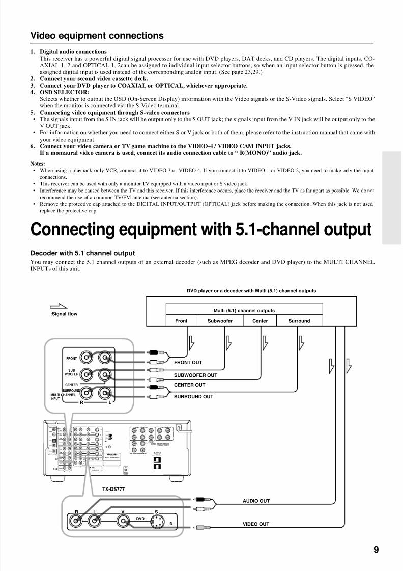
Decoder with 5.1 channel output
You may connect the 5.1 channel outputs of an external decoder (such as MPEG decoder and DVD player) to the MULTI CHANNELINPUTs of this unit.
:Signal flow
DVD player or a decoder with Multi (5.1) channel outputs
FRONT OUT
SUBWOOFER OUT
CENTER OUT
SURROUND OUT
TX-DS777
AUDIO OUT
VIDEO OUT
Multi (5.1) channel outputs
Front Subwoofer Center Surround
Connecting equipment with 5.1-channel output
Video equipment connections
1. Digital audio connectionsThis receiver has a powerful digital signal processor for use with DVD players, DAT decks, and CD players. The digital inputs, CO-AXIAL 1, 2 and OPTICAL 1, 2can be assigned to individual input selector buttons, so when an input selector button is pressed, theassigned digital input is used instead of the corresponding analog input. (See page 23,29.)
2. Connect your second video cassette deck.3. Connect your DVD player to COAXIAL or OPTICAL, whichever appropriate.4. OSD SELECTOR:
Selects whether to output the OSD (On-Screen Display) information with the Video signals or the S-Video signals. Select "S VIDEO"when the monitor is connected via the S-Video terminal.5. Connecting video equipment through S-video connectors• The signals input from the S IN jack will be output only to the S OUT jack; the signals input from the V IN jack will be output only to the
V OUT jack.• For information on whether you need to connect either S or V jack or both of them, please refer to the instruction manual that came with
your video equipment.6. Connect your video camera or TV game machine to the VIDEO-4 / VIDEO CAM INPUT jacks.
If a momaural video camera is used, connect its audio connection cable to “ R(MONO)” audio jack.
Notes:
• When using a playback-only VCR, connect it to VIDEO 3 or VIDEO 4. If you connect it to VIDEO 1 or VIDEO 2, you need to make only the inputconnections.
• This receiver can be used with only a monitor TV equipped with a video input or S video jack.• Interference may be caused between the TV and this receiver. If this interference occurs, place the receiver and the TV as far apart as possible. We do not
recommend the use of a common TV/FM antenna (see antenna section).• Remove the protective cap attached to the DIGITAL INPUT/OUTPUT (OPTICAL) jack before making the connection. When this jack is not used,replace the protective cap.

8/7/2019 Onkyo TX-DS676
http://slidepdf.com/reader/full/onkyo-tx-ds676 10/64
10
Connecting speakers
Speaker placement
Ideal speaker placement varies depending on the size of your roomand the wall coverings. Here, only typical example of speaker place-ment and recommendations are shown.
Speaker systemsLeft and Right front speakers and Center speaker• Place these three speakers at the same height from the floor.• Place each speaker so that sound is aimed at the audience's ears
at the listening position.Left and Right surround speakers• Place these speakers so that their height is 1 meter higher than
that of the audience's ears.SubwooferTo get the highest bass effect, place a subwoofer.You can place your subwoofer anywhere in your room because theplacement affects very little the perceived sound.
1 TV or Screen
2 Front speaker Left
3 Subwoofer4 Center speaker
5 Front speaker Right
6 Surround speaker Left
7 Surround speaker Right
8 Listening Position
1
2 3 54
6 7
8
The TX-DS777/676 allows you to connect two speaker systems.Before connecting the speakers, place them correctly by consulting the instruction manuals that came with your speakers.For surround playback (see “Using the listening modes” on page 34), the configuration and placement of your speakers are very important.For Home THX cinema surround playback, we recommend that you use a THX speaker system that is certified by Lucasfilm Ltd. (such asOnkyo HTS SYSTEM-2).
Ideal speaker configuration:• Right and Left front speakers• Center speaker
Produces a rich sound image by serving as a sound source forthe Right and Left front speakers and enhancing the sonic move-ment.
• Right and Left surround speakersAdds three-dimensional sonic movement and produces environ-mental sound associated with the background and effect soundfor each scene.
• SubwooferProduces powerful and heavy bass.
Minimum speaker configuration for surround sound playback:• Right and Left front speakers• Right and Left surround speakers
The sound recorded for the center speaker and the subwoofer will beproperly distributed to the Right and Left front speakers and theRight and Left surround speakers for optimized surround playback.

8/7/2019 Onkyo TX-DS676
http://slidepdf.com/reader/full/onkyo-tx-ds676 11/64
11
R VLR L
R L
R L
R L
VIDEO-1
OUT
IN
VIDEO-2
VIDEO-3
OUT
IN
IN
TAPE
VIDEO
S VIDEO
OSD SELECTOR
(REC)
OUT
IN
(PLAY)
DIGITAL OUTPUT
DIGITAL INPUT
COAXIAL1
COAXIAL2
OPTICAL1
OPTICAL2
OPTICAL
FRONT
FRONT
CENTER
SUBWOOFER
SURROUND
FRONT
CENTER
CD
PHONO
SUBWOOFER
SURROUND
AMP IN
PRE OUT
GMD
MONITOR
OUT
S
V S
REMOTE
CONTROL
IN
DVD
LR LR
LR
S URRO UND S PE AKE RS F RONT S P EAKERS A
CENTERSPEAKER
FRONT SPEAKERS B
MULTI CHANNELINPUT
AV RECEIVER
CAUTION: SPEAKER IMPEDANCE6 OHMS MIN. / SPEAKER
ANTENNA
AM
FM75
AC OUTLETSAC 120V 60Hz
SWITCHEDTOTAL 120W 1A MAX.
MODEL NO. TX-DS777
R LR
LR
SURROUND SPEAKERS FRONT SPEAKERS A
CENTERSPEAKER
FRONT SPEAKERS B
L
Connecting speakers
• This receiver is designed to produce optimum sound quality when speakers with impedances within the specified ranges are connected.Please check the following information and choose speakers with appropriate impedances for the connections.
FRONTSPEAKERS: A or B: 6 ohms min./speakerSURROUNDSPEAKERS: 6 ohms min./speakerCENTERSPEAKER: 6 ohms min.
TX-DS777/TX-DS676
Center Speaker
Surround Speaker
R ch.
Front SpeakerA
R ch.
Surround Speaker
L ch.
Front SpeakerA
L ch.
Note:
To prevent damage to circuitry, never short-circuitthe positive (+) and negative (–) speaker wire.
• When you use only onespeaker or wish to listen tomonaural (mono) sound, asingle speaker should neverbe connected in parallel toboth the right and left chan-nel terminals simulta-neously.+ – – + + – – +
R L R L
Connecting the speaker cable
1. Twist wire ends very tight.
2. Unscrew 3. Insert wire 4. Screw
Use Front SPEAKERS B termi-
nals to connect a second pair of
front speakers.
15mm
No!
No!

8/7/2019 Onkyo TX-DS676
http://slidepdf.com/reader/full/onkyo-tx-ds676 12/64
12
R VLR L
R L
R L
R L
VIDEO-1
OUT
IN
VIDEO-2
VIDEO-3
OUT
IN
IN
TAPE
VIDEO
S VIDEO
OSD SELECTOR
(REC)
OUT
IN
(PLAY)
DIGITAL OUTPUT
DIGITAL INPUT
COAXIAL1
COAXIAL2
OPTICAL1
OPTICAL2
OPTICAL
FRONT
FRONT
CENTER
SUBWOOFER
SURROUND
FRONT
CENTER
CD
PHONO
SUBWOOFER
SURROUND
AMP IN
PRE OUT
GMD
MONITOR
OUT
S
V S
REMOTE
CONTROL
IN
DVD
LR LR
LR
SURROUND SPEAKERS FRONT SPEAKERS A
CENTERSPEAKER
FRONT SPEAKERS B
MULTI CHANNELINPUT
AV RECEIVER
CAUTION: SPEAKER IMPEDANCE6 OHMS MIN. / SPEAKER
ANTENNA
AM
FM75
AC OUTLETSAC 120V 60Hz
SWITCHEDTOTAL 120W 1A MAX.
MODEL NO. TX-DS777
FRONT
CENTER
SUBWOOFER
SURROUND
PRE OUT
Connecting power amplifiers
Connecting power amplifiers
Using auxiliary power amplifiers allows you to listen at louder vol-umes than with the TX-DS777/676 alone. If power amplifiers are
used, connect each speaker to the corresponding power amplifier.When using speakers connected through external power amplifiers,turn OFF the SPEAKERS A.
R VLR L
R L
R L
R L
VIDEO-1
OUT
IN
VIDEO-2
VIDEO-3
OUT
IN
IN
TAPE
VIDEO
S VIDEOOSD SELECTOR
(REC)
OUT
IN
(PLAY)
DIGITAL OUTPUT
DIGITAL INPUT
COAXIAL1
COAXIAL2
OPTICAL1
OPTICAL2
OPTICAL
FRONT
FRONT
CENTER
SUBWOOFER
SURROUND
FRONT
CENTER
CD
PHONO
SUBWOOFER
SURROUND
AMP IN
PRE OUT
GMD
MONITOR
OUT
S
V S
INDVD
MULTI CHANNELINPUT
TX-DS777
TX-DS777/676
R VL
R L
R L
R L
VIDEO-1
OUT
IN
VIDEO-2
VIDEO-3
OUT
IN
IN
TAPE
VIDEO
S VIDEOOSD SELECTOR
(REC)
OUT
IN
(PLAY)
DIGITAL INPUT
COAXIAL1
COAXIAL2
OPTICAL1
OPTICAL2
FRONT
CENTER
SUBWOOFER
SURROUND
FRONT
CENTER
CD
PHONO
SUBWOOFER
SURROUND
PRE OUT
GMD
MONITOR
OUT
S
V S
REMOTE
CONTROL
IN
DVD
LR LR
LR
S URRO UND S P EAKERS F RONT S PE AKE RS A
CENTERSPEAKER
FRONT SPEAKERS B
MULTI CHANNELINPUT
CAUTION: SPEAKER IMPEDANCE6 OHMS MIN. / SPEAKER
ANTENNA
AM
FM75
AC OUTLETSAC 120V 60Hz
SWITCHEDTOTAL 120W 1A MAX.
FRONT
CENTER
SUBWOOFER
SURROUND
PRE OUT
R L
Right front Speaker
Left front Speaker
Subwoofer
Center Speaker
Left Surround Speaker
Right Surround Speaker
Notes:• Keep the jumper plugs so that you will not
lose them.• When the connectors are not in use, replace
the jumper plugs.
Connecting speakers
Connecting a subwoofer
Use the PREOUT SUBWOOFER jack to connect a subwoofer witha built-in power amplifier. If your subwoofer does not have a built-
in amplifier, connect an amplifier to the PREOUT SUBWOOFERjack and the subwoofer to the amplifier.
:Signal flow
8/7/2019 Onkyo TX-DS676
http://slidepdf.com/reader/full/onkyo-tx-ds676 13/64
13
Connecting the power
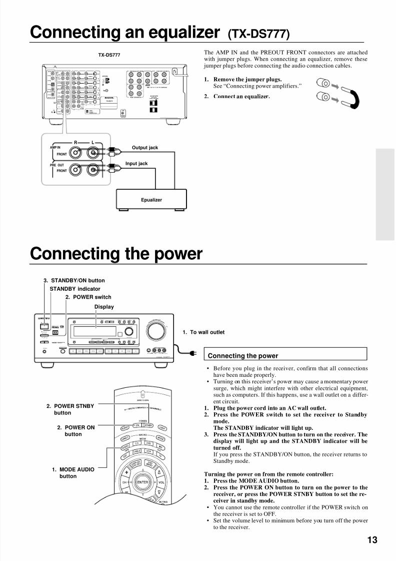
Connecting the power
• Before you plug in the receiver, confirm that all connectionshave been made properly.
• Turning on this receiver’s power may cause a momentary powersurge, which might interfere with other electrical equipment,
such as computers. If this happens, use a wall outlet on a differ-ent circuit.
1. Plug the power cord into an AC wall outlet.2. Press the POWER switch to set the receiver to Standby
mode.The STANDBY indicator will light up.
3. Press the STANDBY/ON button to turn on the receiver. Thedisplay will light up and the STANDBY indicator will beturned off.If you press the STANDBY/ON button, the receiver returns toStandby mode.
Turning the power on from the remote controller:1. Press the MODE AUDIO button.2. Press the POWER ON button to turn on the power to the
receiver, or press the POWER STNBY button to set the re-ceiver in standby mode.
• You cannot use the remote controller if the POWER switch onthe receiver is set to OFF.
• Set the volume level to minimum before you turn off the powerto the receiver.
2. POWER ON
button
MASTER VOLUME
STANDBY/ON
PHONESVIDEO CAM INPUT/ 4VIDEO
V I DE O A U DI OL R(MONO)S VIDEO
STAND-BY
AV RECEIVER TX-DS777
POWER
OFFON
A SPEAKERS B
TI CH INPUTMUL
FM AM PHONO C DTAPEVIDEO-1DVD VIDEO-4VIDEO-3VIDEO-2
DOWN
U P
FM MUTE/ MODE
CHARACTER/ MEMORY
SP/SYSSETUP
MODE
AUDIOADJUSTMENT
BASS/ TREBLE
DISPLAY DSP REC OUT
PRESET/MODE ADJ
PUSH TO ENTER
DOWN TUNING UP
THX/DTS
SURROUND MODE
LISTENING MODE
STEREODIRECTDIGITAL/ ANALOG CH LEVEL
DIMMER
2. POWER STNBY
button
1. MODE AUDIO
button
3. STANDBY/ON button
STANDBY indicator
Display
2. POWER switch
1. To wall outlet
Connecting an equalizer (TX-DS777)
The AMP IN and the PREOUT FRONT connectors are attachedwith jumper plugs. When connecting an equalizer, remove thesejumper plugs before connecting the audio connection cables.
1. Remove the jumper plugs.See “Connecting power amplifiers.”
2. Connect an equalizer.
TX-DS777
Input jack
R VLR L
R L
R L
R L
VIDEO-1
OUT
IN
VIDEO-2
VIDEO-3
OUT
IN
IN
TAPE
VIDEO
S VIDEOOSD SELECTOR
(REC)
OUT
IN
(PLAY)
DIGITAL OUTPUT
DIGITAL INPUT
COAXIAL1
COAXIAL2
OPTICAL1
OPTICAL2
OPTICAL
FRONT
FRONT
CENTER
SUBWOOFER
SURROUND
FRONT
CENTER
CD
PHONO
SUBWOOFER
SURROUND
AMP IN
PRE OUT
GMD
MONITOR
OUT
S
V S
REMOTE
CONTROL
IN
DVD
LR LR
LR
S URROUND S PE AKE RS F RONT S PE AKE RS A
CENTERSPEAKER
FRONT SPEAKERS B
MULTI CHANNELINPUT
TX-DS777
ANTENNA
AM
FM75
AC OUTLETSSWITCHED
TOTAL 100W MAX.
W
R L
FRONT
FRONT
AMP IN
PRE OUT
Output jack
Input jack
Epualizer

8/7/2019 Onkyo TX-DS676
http://slidepdf.com/reader/full/onkyo-tx-ds676 14/64
14
Making antenna connections
Connecting the antenna cable to the 75/300 ohmantenna adapter (Other than North America andEuropean models)
Connecting the 300 ohm ribbon wire:Loosen the screws and wrap the wire around these screws. Then
tighten the screws with a screwdriver.
Connecting the coaxial cable:1. With your fingernail or a small screwdriver, press the stoppers
outward and remove the cover.2. Remove the transformer wire A from slit B and insert it into slit
C.3. Prepare the coaxial cable as shown in the diagram.
Connect the 75/300 ohm antenna adapter to the coaxial cable.1 Insert the end of the cable.2 Clamp it in place with pliers.
4. Re-install the cover.
Directional Iinkage
Do not use the same antenna for both FM and TV (or VCR) recep-tion since the FM and TV (or VCR) signals can interfere with eachother. If you must use a common FM/TV (or VCR) antenna, use adirectional linkage type splitter.
Assembling the AM loop antenna
Assemble the loop antenna as shown in the illustration.• Refer to the next page for details on connecting the AM loop
antenna.
Connecting the antenna cable
1. Press down the lever.2. Insert the wire into the hole.3. Release the lever to replace it.
1 2 3
6mm
3mm
6mm
15mm
1 2 3
Outdoor
antenna
Indoor
antenna
300 ohms
ribbon wire
Slit B
Wire A
Slit C
Directional linkagetype splitter
To TV (or VCR)To receiver
Insert into the hole.

8/7/2019 Onkyo TX-DS676
http://slidepdf.com/reader/full/onkyo-tx-ds676 15/64
15
Connecting the included antennas
Connecting the FM indoor antenna:The FM indoor antenna is for indoor use only. Extend the antennaand move it in various directions until the clearest signal is received.Fix it with push pins or similar implements in the position that will
cause the least amount of distortion.If the reception is not very clear with the attached FM indoor an-tenna, the use of an outdoor antenna is recommended.
Making antenna connections
Connecting an FM outdoor antenna
Please make sure that you follow the considerations below regard-
ing the location.Keep the antenna away from noise sources (neon signs, busy roads,etc.).It is dangerous to put the antenna close to power lines. Keep it wellaway from power lines, transformers, etc.
• To avoid the risk of lightning and electrical shock, grounding isnecessary. Follow item 19 of the “Important Safeguards” onpage 2 when you install the outdoor antenna.
Connecting the AM loop antenna:The AM loop antenna is for indoor use only. Set it in the directionand position where you receive the clearest sound. Put it as far awayas possible from the unit, TVs, speaker cables, and power cords.When reception is not satisfactory with the attached AM loop an-tenna alone, connection of an outdoor antenna is recommended.
AM
FM75
ANTENNA
Remove the insulation atthe end of the cable, thenfully insert the strippedend of the cable.
AM
FM75
ANTENNA
AM
FM75
ANTENNA
U.S. and Canadian
models
Others
Outdoor
antenna
Connecting an AM outdoor antenna
The outdoor antenna will be more effective if it is stretched horizon-tally above a window or outside.
• Do not remove the AM loop antenna.• To avoid the risk of lightning and electrical shock, grounding is
necessary. Follow item 19 of the “Important Safeguards” onpage 2 when you install the outdoor antenna.
8/7/2019 Onkyo TX-DS676
http://slidepdf.com/reader/full/onkyo-tx-ds676 16/64
16
1
2~4
Using the on-screen display
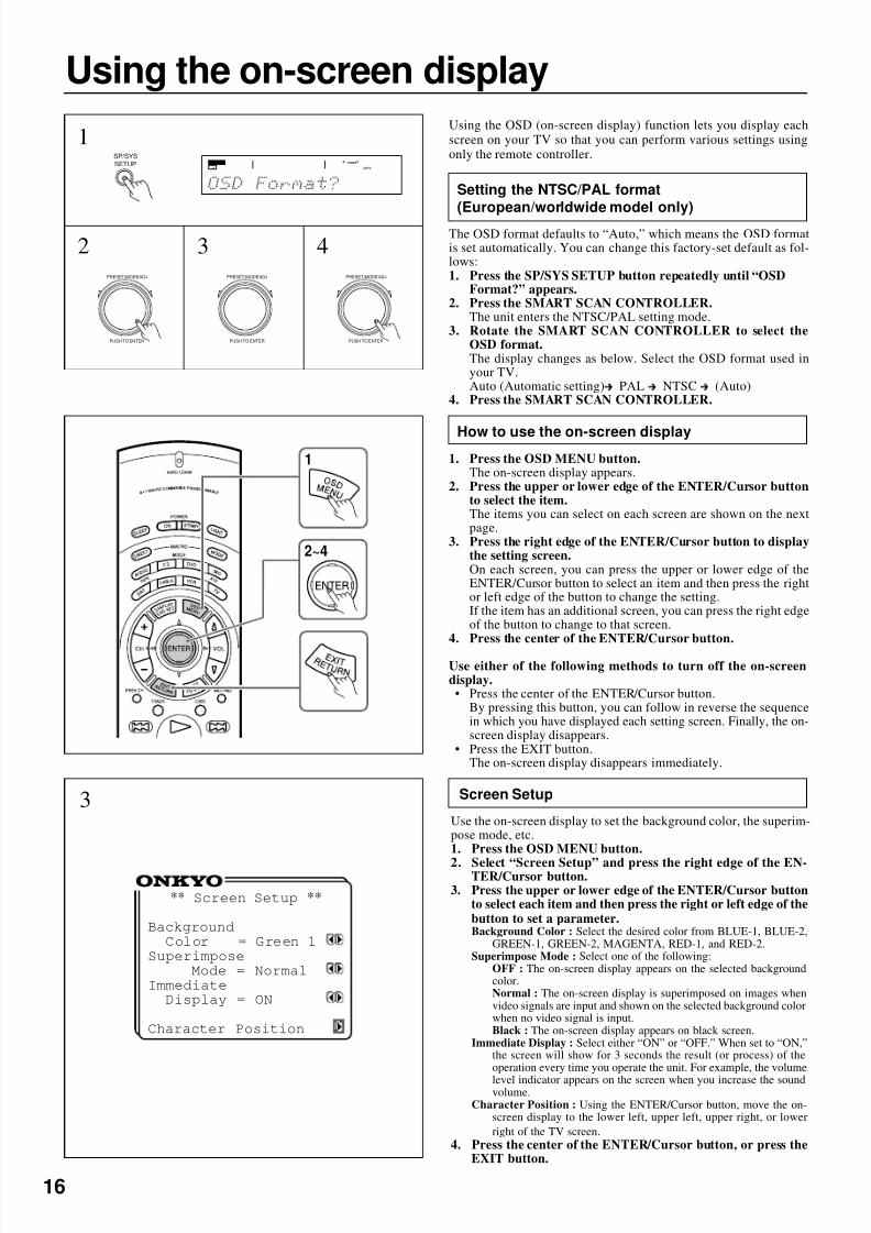
Using the OSD (on-screen display) function lets you display eachscreen on your TV so that you can perform various settings usingonly the remote controller.
Setting the NTSC/PAL format(European/worldwide model only)
The OSD format defaults to “Auto,” which means the OSD formatis set automatically. You can change this factory-set default as fol-lows:1. Press the SP/SYS SETUP button repeatedly until “OSD
Format?” appears.2. Press the SMART SCAN CONTROLLER.
The unit enters the NTSC/PAL setting mode.3. Rotate the SMART SCAN CONTROLLER to select the
OSD format.The display changes as below. Select the OSD format used inyour TV.Auto (Automatic setting) PAL NTSC (Auto)
4. Press the SMART SCAN CONTROLLER.
How to use the on-screen display
1. Press the OSD MENU button.The on-screen display appears.
2. Press the upper or lower edge of the ENTER/Cursor buttonto select the item.The items you can select on each screen are shown on the nextpage.
3. Press the right edge of the ENTER/Cursor button to displaythe setting screen.On each screen, you can press the upper or lower edge of theENTER/Cursor button to select an item and then press the rightor left edge of the button to change the setting.If the item has an additional screen, you can press the right edgeof the button to change to that screen.
4. Press the center of the ENTER/Cursor button.
Use either of the following methods to turn off the on-screendisplay.• Press the center of the ENTER/Cursor button.
By pressing this button, you can follow in reverse the sequencein which you have displayed each setting screen. Finally, the on-screen display disappears.
• Press the EXIT button.The on-screen display disappears immediately.
2
1SP/SYSSETUP
PRESET/MODE ADJ
PUSH TO ENTER
** Screen Setup **
BackgroundColor = Green 1
SuperimposeMode = Normal
ImmediateDisplay = ON
Character Position
Screen Setup
Use the on-screen display to set the background color, the superim-pose mode, etc.1. Press the OSD MENU button.
2. Select “Screen Setup” and press the right edge of the EN-TER/Cursor button.
3. Press the upper or lower edge of the ENTER/Cursor buttonto select each item and then press the right or left edge of thebutton to set a parameter.Background Color : Select the desired color from BLUE-1, BLUE-2,
GREEN-1, GREEN-2, MAGENTA, RED-1, and RED-2.Superimpose Mode : Select one of the following:
OFF : The on-screen display appears on the selected backgroundcolor.Normal : The on-screen display is superimposed on images whenvideo signals are input and shown on the selected background colorwhen no video signal is input.Black : The on-screen display appears on black screen.
Immediate Display : Select either “ON” or “OFF.” When set to “ON,”the screen will show for 3 seconds the result (or process) of theoperation every time you operate the unit. For example, the volume
level indicator appears on the screen when you increase the soundvolume.Character Position : Using the ENTER/Cursor button, move the on-
screen display to the lower left, upper left, upper right, or lowerright of the TV screen.
4. Press the center of the ENTER/Cursor button, or press theEXIT button.
3
SPEAKERS
A
TUNED
AUTO
3 4PRESET/MODE ADJ
PUSH TO ENTER
PRESET/MODE ADJ
PUSH TO ENTER
8/7/2019 Onkyo TX-DS676
http://slidepdf.com/reader/full/onkyo-tx-ds676 17/64
17
Using the on-screen display
*** Menu ***
Input Selector
Rec SelectorListening Mode Setup
Speaker SetupScreen Setup
** Input Selector **
Input = DVDOPTICAL 1
Digital Input SetupVideo Assign SetupIntelliVolume SetupListening Dolby
Mode= Pro LogicTHX Cinema
** Rec Selector **
•Picture VIDEO=DVD 1,2
•Sound TAPE=DVD VIDEO
1,2•Digital OPTICAL=---- OUT
** Listening Mode **
SetupListening
Mode=Mono Movie
Front Effect = ONReflect Level = 0dBReverb Level = 0dBRoom Size =Mid
Default
** Speaker Setup **
Config Setup
Distance Setup
Level Setup
Bass Peak Setup
** Screen Setup **
BackgroundColor = Green 1
SuperimposeMode = NormalImmediateDisplay = ON
Character Position
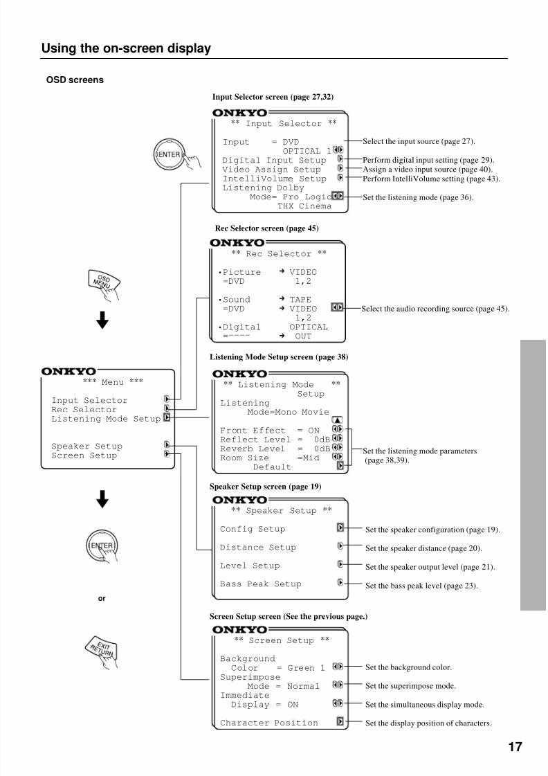
Input Selector screen (page 27,32)
Rec Selector screen (page 45)
Listening Mode Setup screen (page 38)
Speaker Setup screen (page 19)
Screen Setup screen (See the previous page.)
OSD screens
or
Select the input source (page 27).
Perform digital input setting (page 29).Assign a video input source (page 40).Perform IntelliVolume setting (page 43).
Set the listening mode (page 36).
Set the speaker configuration (page 19).
Set the speaker distance (page 20).
Set the speaker output level (page 21).
Set the bass peak level (page 23).
Set the background color.
Set the superimpose mode.
Set the simultaneous display mode.
Set the display position of characters.
Set the listening mode parameters(page 38,39).
Select the audio recording source (page 45).

8/7/2019 Onkyo TX-DS676
http://slidepdf.com/reader/full/onkyo-tx-ds676 18/64
18
Setting the speaker configuration
Setting the speaker configuration parameters
Using the SMART SCAN CONTROLLER, you can easily set thespeaker configuration. Turn it to select the parameter and press it togo to the next item.1. Press the SP/SYS SETUP button.
“Config Setup?” appears. Then Press the SMART SCAN CON-TROLLER.
2. For the TX-DS676, go to the next step.For the TX-DS777, “All Ch For THX” appears.Set “Yes” or “No.”Yes: Your system is a THX speaker system.
(The following steps are unnecessary.)No : Your system is a non-THX speaker system.Press the SMART SCAN CONTROLLER.
3. Set whether or not a subwoofer is connected.Yes: A subwoofer is connected.No: A subwoofer is NOT connected.Press the SMART SCAN CONTROLLER.
4. Select the size of your front speakers.Large: Large front speakers are used.Small: Small front speakers are used.Press the SMART SCAN CONTROLLER.
5. Select the size of your center speaker.Large: A large center speaker is used.Small: A small center speaker is used.None: A center speaker is NOT used.
Press the SMART SCAN CONTROLLER.6. Select the size of your surround speakers.Large: Large surround speakers are used.Small: Small surround speakers are used.None: Surround speakers are NOT used.
7. Press the SMART SCAN CONTROLLER.This completes the speaker configuration setup.
1
2
3 ~ 6
SMART SCAN CONTROLLERSP/SYS SETUP button
Perform this setup before using the unit.
MASTER VOLUME
STANDBY/ON
PHONESVIDEO CAM INPUT/ 4VIDEO
V ID EO A UD IOL R(MONO)S VIDEO
STAND-BY
AV RECEIVER TX-DS777
POWER
OFFON
A SPEAKERS B
TI CH INPUTMUL
FM AM PHONO C DTAPEVIDEO-1DVD VIDEO-4VIDEO-3VIDEO-2
DOWN
U P
FM MUTE/
MODE
CHARACTER/
MEMORY
SP/SYS
SETUP
SMART SCAN
CONTROLLER
MODE
AUDIO
ADJUSTMENT
BASS/
TREBLE
DISPLAY DSP REC OUT
PRESET/MODE ADJ
PUSH TO ENTER
DOWN TUNING UP
THX/DTS
SURROUND MODE
LISTENING MODE
STEREODIRECTDIGITAL/
ANALOG CH LEVEL
DIMMER
SP/SYS
SETUP
PRESET/MODE ADJ
PUSH TO ENTER
SPEAKERS
A
TUNED
AUTO
SPEAKERS
A
TUNED
AUTO
SPEAKERS
A FM STEREO AUTO
TUNED
Front
Center
Surround
7PRESET/MODE ADJ
PUSH TO ENTER
PRESET/MODE ADJ
PUSH TO ENTER
PRESET/MODE ADJ
PUSH TO ENTER
PRESET/MODE ADJ
PUSH TO ENTER
PRESET/MODE ADJ
PUSH TO ENTER
TX-DS777 only
(The layout of buttons, switches, and other controls on the front
panel may vary depending where the unit is purchased.)
8/7/2019 Onkyo TX-DS676
http://slidepdf.com/reader/full/onkyo-tx-ds676 19/64
19
Setting the speaker configuration
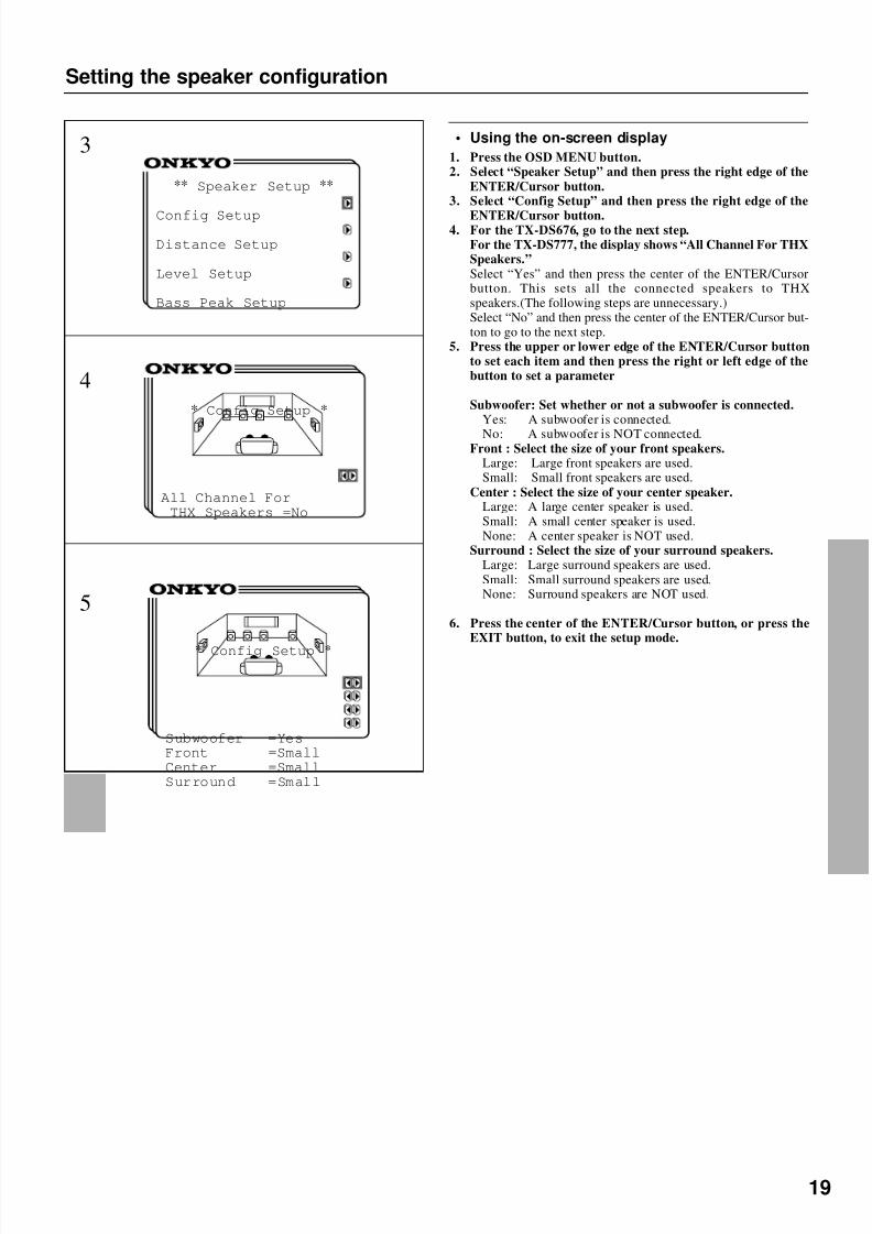
• Using the on-screen display
1. Press the OSD MENU button.2. Select “Speaker Setup” and then press the right edge of the
ENTER/Cursor button.3. Select “Config Setup” and then press the right edge of the
ENTER/Cursor button.4. For the TX-DS676, go to the next step.
For the TX-DS777, the display shows “All Channel For THXSpeakers.”Select “Yes” and then press the center of the ENTER/Cursorbutton. This sets all the connected speakers to THXspeakers.(The following steps are unnecessary.)Select “No” and then press the center of the ENTER/Cursor but-ton to go to the next step.
5. Press the upper or lower edge of the ENTER/Cursor buttonto set each item and then press the right or left edge of thebutton to set a parameter
Subwoofer: Set whether or not a subwoofer is connected.Yes: A subwoofer is connected.
No: A subwoofer is NOT connected.Front : Select the size of your front speakers.
Large: Large front speakers are used.Small: Small front speakers are used.
Center : Select the size of your center speaker.Large: A large center speaker is used.Small: A small center speaker is used.None: A center speaker is NOT used.
Surround : Select the size of your surround speakers.Large: Large surround speakers are used.Small: Small surround speakers are used.None: Surround speakers are NOT used.
6. Press the center of the ENTER/Cursor button, or press theEXIT button, to exit the setup mode.
3
4
5
** Speaker Setup **
Config Setup
Distance Setup
Level Setup
Bass Peak Setup
* Config Setup *
All Channel ForTHX Speakers =No
* Config Setup *
Subwoofer =YesFront =SmallCenter =SmallSurround =Small
8/7/2019 Onkyo TX-DS676
http://slidepdf.com/reader/full/onkyo-tx-ds676 20/64
20
PRESET/MODE ADJ
PUSH TO ENTER
SP/SYSSETUP
Setting the speaker distance
Setting the distance from each speaker to thelistening position(Loudspeaker Position Time Synchronization*)
Select a value that is closest to the actual distance between eachspeaker and the listening position.
Using the SMART SCAN CONTROLLER, you can easily set thespeaker configuration. Turn it to select the setting and press it to goto the next item.For each speaker, you can set a distance of 0.3 meter to 9.0 meters(or 1 foot to 30 feet) in increments of 30 cm (1 foot).1. Press the SP/SYS SETUP button repeatedly until “Distance
Setup ?” appears.Press the SMART SCAN CONTROLLER.
2. “Left=” appears. Set the distance from the left frontspeaker.Press the SMART SCAN CONTROLLER.
3. “Center=” appears. Set the distance from the centerspeaker.Press the SMART SCAN CONTROLLER.
4. “Right=” appears. Set the distance from the Right front
speaker.Press the SMART SCAN CONTROLLER.
5. “R-Sur=” appears. Set the distance from the Right surroundspeaker.Press the SMART SCAN CONTROLLER.
6. “L-Sur=” appears Set the distance from the left surroundspeaker.Press the SMART SCAN CONTROLLER.
7. “SW=” appears. Set the distance from the subwoofer.8. Press the SMART SCAN CONTROLLER.
The speaker distance setup has been completed.
* Loudspeaker Position Time Synchronization is a registered trademark of Lucasfilm LTD.
1
2 ~ 7
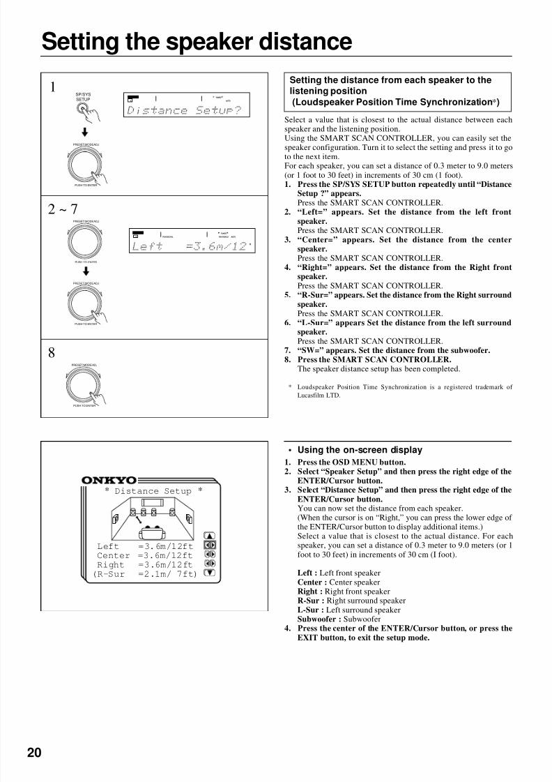
• Using the on-screen display
1. Press the OSD MENU button.2. Select “Speaker Setup” and then press the right edge of the
ENTER/Cursor button.3. Select “Distance Setup” and then press the right edge of the
ENTER/Cursor button.You can now set the distance from each speaker.(When the cursor is on “Right,” you can press the lower edge of the ENTER/Cursor button to display additional items.)Select a value that is closest to the actual distance. For each
speaker, you can set a distance of 0.3 meter to 9.0 meters (or 1foot to 30 feet) in increments of 30 cm (I foot).
Left : Left front speakerCenter : Center speakerRight : Right front speakerR-Sur : Right surround speakerL-Sur : Left surround speakerSubwoofer : Subwoofer
4. Press the center of the ENTER/Cursor button, or press theEXIT button, to exit the setup mode.
* Distance Setup *
Left =3.6m/12ftCenter =3.6m/12ftRight =3.6m/12ft(R-Sur =2.1m/ 7ft)
SPEAKERS
A AUTO
TUNED
PRESET/MODE ADJ
PUSH TO ENTER
PRESET/MODE ADJ
PUSH TO ENTER
PRESET/MODE ADJ
PUSH TO ENTER
SPEAKERS
A PCM DIGITAL FM STEREO
TUNED
AUTO
ft
8

8/7/2019 Onkyo TX-DS676
http://slidepdf.com/reader/full/onkyo-tx-ds676 21/64
21
2
Using the test tone to adjust the speaker outputlevels
1. Press the SP/SYS SETUP button repeatedly until“Level Setup?” appears.Press the SMART SCAN CONTROLLER.
The display shows “Left.”2. Rotate clockwise or counterclockwise the SMART SCAN
CONTROLLER to adjust the speaker output level.You can adjust the output level of each speaker in the range of 12 to +12 dB, except for the subwoofer whose adjustment rangeis -30 to +10 dB.Press the SMART SCAN CONTROLLER.You hear a test tone (pink noise) from the left front speaker.Each time you press the SMART SCAN CONTROLLER, thespeaker that produces a test tone changes as below. Set the out-put level of each speaker by rotating the SMART SCAN CON-TROLLER so that you can hear the same level of test tone at thelistening position.Left (Left front) Center (Center) Right (Right front) R-Sur(Right surround) L-Sur(Left surround) Subwoofer (Subwoofer)
Left
Notes:
• In order to correctly set the output levels, use a hand-held SoundPressure Level meter (SPL), set to C-Weighting and Slow aver-aging. A Radio Shack® SPL meter (catalogue number 330-2055) or equivalent can be used. Using the internal channelnoise generators, set each channel so that you read 75 dB SPLfrom each channel.
• SPEAKER B, when selected, will be deselected automaticallyas soon as the test tone starts sounding. The Test Tone functionis not available when the headphones are connected or whenMULTI CH INPUT is selected.
• The test tone will not be output from the speaker that has been set to"No" in the configuration setup explained on the page 18,19.
• If the speaker level is set to +1dB or higher , the maximum level indi-cated on the display will change if you raise the volume level.
Setting the speaker Level
• Using the on-screen display
1. Press the OSD MENU button.2. Select “Speaker Setup” and then press the right edge of the
ENTER/Cursor button.3. Select “Level Setup” and then press the right edge of the
ENTER/Cursor button.The Level Setup screen appears and a test tone (pink noise) isoutput from the left front speaker. You can change the speakerthat outputs the test tone in the following sequence.(When thecursor is on “Center,” you can press the lower edge of the EN-TER/Cursor button to display additional items.)
Left (Left front) Center (Center) Right (Right front) R-Sur(Right surround) L-Sur (Left surround) Subwoofer (Subwoofer)
Left.4. Set the output level of each speaker so that you can hear the
same level of test tone at the listening position.You can adjust the output level of each speaker in the range of -12 to +12 dB, except for the subwoofer whose adjustment rangeis -30 to +10 dB.
5. Press the center of the ENTER/Cursor button, or press theEXIT button, to exit the setup mode.
* Level Setup *
Left = +1dBCenter = 0dB(Right = 0dB)
SP/SYS
SETUP1
PRESET/MODE ADJ
PUSH TO ENTER
PRESET/MODE ADJ
PUSH TO ENTER
PRESET/MODE ADJ
PUSH TO ENTER
SPEAKERS
A PCM DIGITAL
STEREO
db
Center
Right
R-Sur
L-Sur
SW
• Using Test button on the remote controller
1. Press the MODE AUDIO button.2. Press the TEST button.
Left front speaker produces the test tone (pink noise).3. To adjust the level of each speaker,press the CH SEL, but-
ton to select a speaker and press the LEVEL +/- buttons toraise or lower the level.
4. Press rhe TEST button to complete adjustment.
1
2 3 4
SPEAKERS
A
DSP
8/7/2019 Onkyo TX-DS676
http://slidepdf.com/reader/full/onkyo-tx-ds676 22/64
22
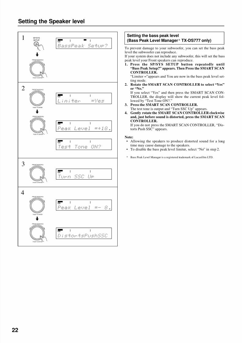
Setting the bass peak level(Bass Peak Level Manager* TX-DS777 only)
To prevent damage to your subwoofer, you can set the bass peaklevel the subwoofer can reproduce.If your system does not include any subwoofer, this will set the bass
peak level your Front speakers can reproduce.1. Press the SP/SYS SETUP button repeatedly until
“Bass Peak Setup?” appears. Then Press the SMART SCANCONTROLLER.“Limiter =”appears and You are now in the bass peak level set-ting mode.
2. Rotate the SMART SCAN CONTROLLER to select “Yes”or “No.”If you select “Yes” and then press the SMART SCAN CON-TROLLER, the display will show the current peak level fol-lowed by “Test Tone ON?.”
3. Press the SMART SCAN CONTROLLER.The test tone is output and “Turn SSC Up” appears.
4. Gently rotate the SMART SCAN CONTROLLER clockwiseand, just before sound is distorted, press the SMART SCAN
CONTROLLER.If you do not press the SMART SCAN CONTROLLER, “Dis-torts Push SSC” appears.
Note:• Allowing the speakers to produce distorted sound for a long
time may cause damage to the speakers.• To disable the bass peak level limiter, select “No” in step 2.
* Bass Peak Level Manager is a registered trademark of Lucasfilm LTD.
Setting the Speaker level
1
2
3
4
SP/SYS
SETUP
PRESET/MODE ADJ
PUSH TO ENTER
PRESET/MODE ADJ
PUSH TO ENTER
PRESET/MODE ADJ
PUSH TO ENTER
PRESET/MODE ADJ
PUSH TO ENTER
PRESET/MODE ADJ
PUSH TO ENTER
SPEAKERS
A
DSP
SPEAKERS
A
SPEAKERS
A
SPEAKERS
A
SPEAKERS
A
SPEAKERS
A
db
SPEAKERS
A
db
PRESET/MODE ADJ
PUSH TO ENTER
8/7/2019 Onkyo TX-DS676
http://slidepdf.com/reader/full/onkyo-tx-ds676 23/64
23
PRESET/MODE ADJ
PUSH TO ENTER
PRESET/MODE ADJ
PUSH TO ENTER
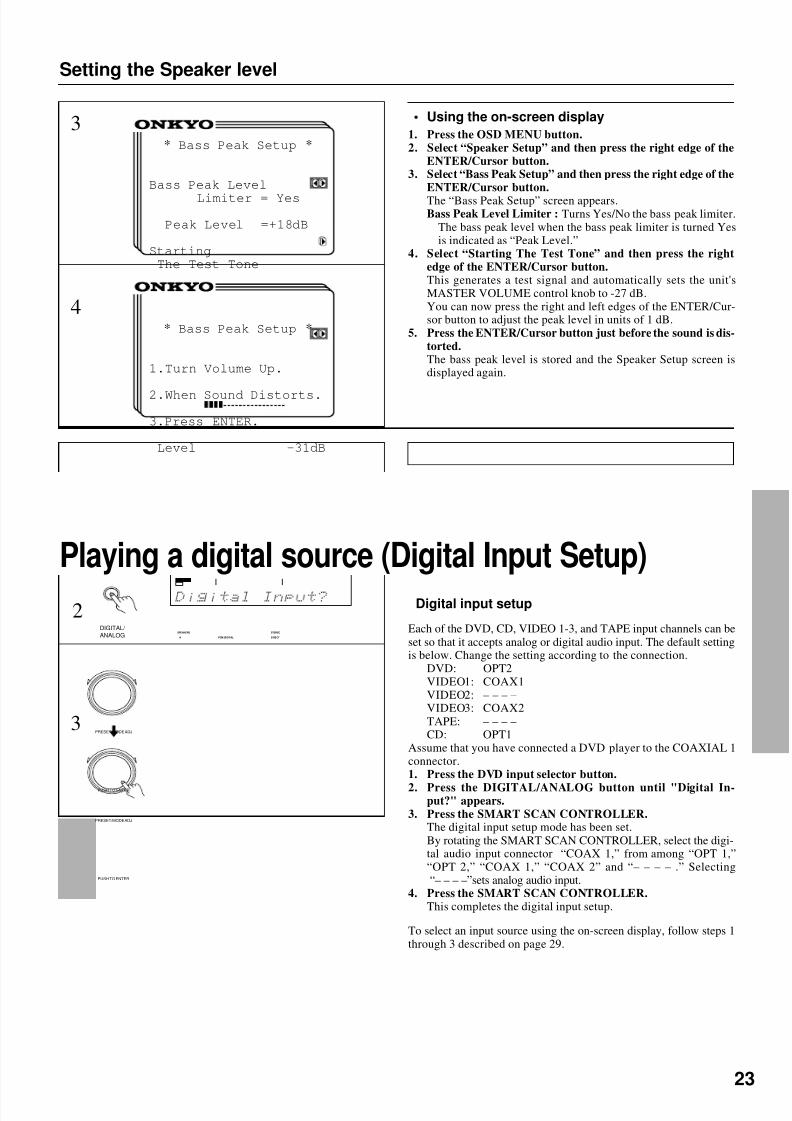
• Using the on-screen display
1. Press the OSD MENU button.2. Select “Speaker Setup” and then press the right edge of the
ENTER/Cursor button.3. Select “Bass Peak Setup” and then press the right edge of the
ENTER/Cursor button.
The “Bass Peak Setup” screen appears.Bass Peak Level Limiter : Turns Yes/No the bass peak limiter.
The bass peak level when the bass peak limiter is turned Yesis indicated as “Peak Level.”
4. Select “Starting The Test Tone” and then press the rightedge of the ENTER/Cursor button.This generates a test signal and automatically sets the unit'sMASTER VOLUME control knob to -27 dB.You can now press the right and left edges of the ENTER/Cur-sor button to adjust the peak level in units of 1 dB.
5. Press the ENTER/Cursor button just before the sound is dis-torted.The bass peak level is stored and the Speaker Setup screen isdisplayed again.
Setting the Speaker level
Playing a digital source (Digital Input Setup)
SPEAKERS
A PCM DIGITAL DIRECT
STEREO
3
4
* Bass Peak Setup *
Bass Peak Level
Limiter = Yes
Peak Level =+18dB
StartingThe Test Tone
* Bass Peak Setup *
1.Turn Volume Up.
2.When Sound Distorts.
3.Press ENTER.
Level -31dB
Digital input setup
Each of the DVD, CD, VIDEO 1-3, and TAPE input channels can beset so that it accepts analog or digital audio input. The default settingis below. Change the setting according to the connection.
DVD: OPT2VIDEO1: COAX1VIDEO2: – – – –VIDEO3: COAX2TAPE: – – – –CD: OPT1
Assume that you have connected a DVD player to the COAXIAL 1connector.1. Press the DVD input selector button.
2. Press the DIGITAL/ANALOG button until "Digital In-put?" appears.
3. Press the SMART SCAN CONTROLLER.The digital input setup mode has been set.By rotating the SMART SCAN CONTROLLER, select the digi-tal audio input connector “COAX 1,” from among “OPT 1,”“OPT 2,” “COAX 1,” “COAX 2” and “– – – – .” Selecting“– – – –”sets analog audio input.
4. Press the SMART SCAN CONTROLLER.This completes the digital input setup.
DIGITAL/
ANALOG
2
3
To select an input source using the on-screen display, follow steps 1through 3 described on page 29.

8/7/2019 Onkyo TX-DS676
http://slidepdf.com/reader/full/onkyo-tx-ds676 24/64
24
MASTER VOLUME
STANDBY/ON
PHONES
V ID EO A UDI OL RS VIDEO
POWER
OFFON
A SPEAKERS B
FM AM PHONO C DTAPEVIDEO-1DVD VIDEO-4VIDEO-3VIDEO-2
DOWN
U P
FM MUTE/
MODE
CHARACTER/
MEMORY
SP/SYS
SETUP
SMART SCAN
CONTROLLER
MODE
AUDIO
ADJUSTMENT
BASS/
TREBLE
DISPLAY DSP
PRESET/MODE ADJ
PUSH TO ENTER
DOWN TUNING UP
THX/DTS
SURROUND MODE
LISTENING MODE
STEREODIRECT
DIGITAL/
ANALOG CH LEVEL
DIMMER
TI CHMUL INPUT
ANDBYS T T I S OU RC EMUL
DTR -7 by
VIDEO4 (MONO)
AUDIOL R
REC OUT / MULTI SOURCE
DOWN TUNING UP
1
2
Presetting FM/AM radio stations
Tuning in a radio station
1. Press the FM or AM button.2. Use the TUNING UP/DOWN buttons to change the fre-
quency.UP................the frequency increases.DOWN........ the frequency decreases.
• The frequency changes in 50 kHz steps in FM and 10 kHz (or 9kHz) in AM each time you press the TUNING UP/DOWN but-ton.
• In FM, if this button is held continuously for more than 0.5 sec-onds,the frequencies are scanned automatically (FM auto tuningmade).When a broadcast is received, scanning stops.
• The European model allows you to receive RDS broadcasts. Seepage 46 for details.
Listening to a stereo radio station (FM mode)When you tune in a stereo FM station, the FM STEREO indicatorlights up if the signal is sufficiently strong.If the signal is weak, it may be impossible to tune in to the desiredstation. In this case, tune in as follows.
Press the FM MUTE/MODE button. The AUTO indicatorturns off. At this time, the station will be in mono and interstationnoise will be heard. Select the station to which you want to listen.
FM MUTE/
MODE
DISPLAY
FM AM
SPEAKERS
A
DSP
AUTO
TUNED
FM
DISPLAY buttonPressing the DISPLAY button each time will change the indicationas follows:Frequency (preset No.) Listening mode
FM/AM
TUNING UP/DOWN
FM MUTE/MODE CHARACTER/MEMORY
SMART SCAN
CONTROLLER
SPEAKERS
A
SPEAKERS
A

8/7/2019 Onkyo TX-DS676
http://slidepdf.com/reader/full/onkyo-tx-ds676 25/64
25
1
2
Preset ting FM/AM radio stations
Programming radio stations
1. Select the frequency that you want to store in the memory.(See Tuning in a radio station on page 24.)
2. Press the CHARACTER/MEMORY button.“Preset In? ” appears.
3. Press the SMART SCAN CONTROLLER.The “MEMORY” indicator lights up on the display.
4. Select the desired memory number using SMART SCANCONTROLLER.
5. Press the SMART SCAN CONTROLLER.The received station will be stored in the specified preset num-ber.
• A total of 40 stations can be stored in the memory.
SPEAKERS
A
DSP
AUTO
TUNED
CHARACTER/
MEMORY
3PRESET/MODE ADJ
PUSH TO ENTER
PRESET/MODE ADJ
PUSH TO ENTER
4
5 PRESET/MODE ADJ
PUSH TO ENTER
2CHARACTER/
MEMORY
3PRESET/MODE ADJ
PUSH TO ENTER
Cancelling preset stations1. Select the preset station you wish to remove as explained in
the previous section.2. Press the CHARACTER/MEMORY button repeatedly.
“Preset Erase? ” appears on the display.3. Press the SMART SCAN CONTROLLER.“Erase OK ? ” appears.To stop canceling preset stations, press the CHARACTER/ MEMORY button.
4. Press the SMART SCAN CONTROLLER.
SPEAKERS
A
STEREO
AUTO
MEMORY
SPEAKERS
A
DSP
AUTO
TUNED
ch
SPEAKERS
A
STEREO
PRESET/MODE ADJ
PUSH TO ENTER
SPEAKERS
A
STEREO
4
8/7/2019 Onkyo TX-DS676
http://slidepdf.com/reader/full/onkyo-tx-ds676 26/64
26
Selecting an input source
MASTER VOLUME
STANDBY/ON
PHONESVIDEO CAM INPUT/ 4VIDEO
V IDE O A UD IOL R(MONO)S VIDEO
STAND-BY
AV RECEIVER TX-DS777
POWER
OFFON
A SPEAKERS B
TI CH INPUTMUL
FM AM PHONO C DTAPEVIDEO-1DVD VIDEO-4VIDEO-3VIDEO-2
DOWN
U P
FM MUTE/
MODE
CHARACTER/
MEMORY
SP/SYS
SETUP
SMART SCAN
CONTROLLER
MODE
AUDIO
ADJUSTMENT
BASS/
TREBLE
DISPLAY DSP REC OUT
PRESET/MODE ADJ
PUSH TO ENTER
DOWN TUNING UP
THX/DTS
SURROUND MODE
LISTENING MODE
STEREODIRECT
DIGITAL/
ANALOG CH LEVEL
DIMMER
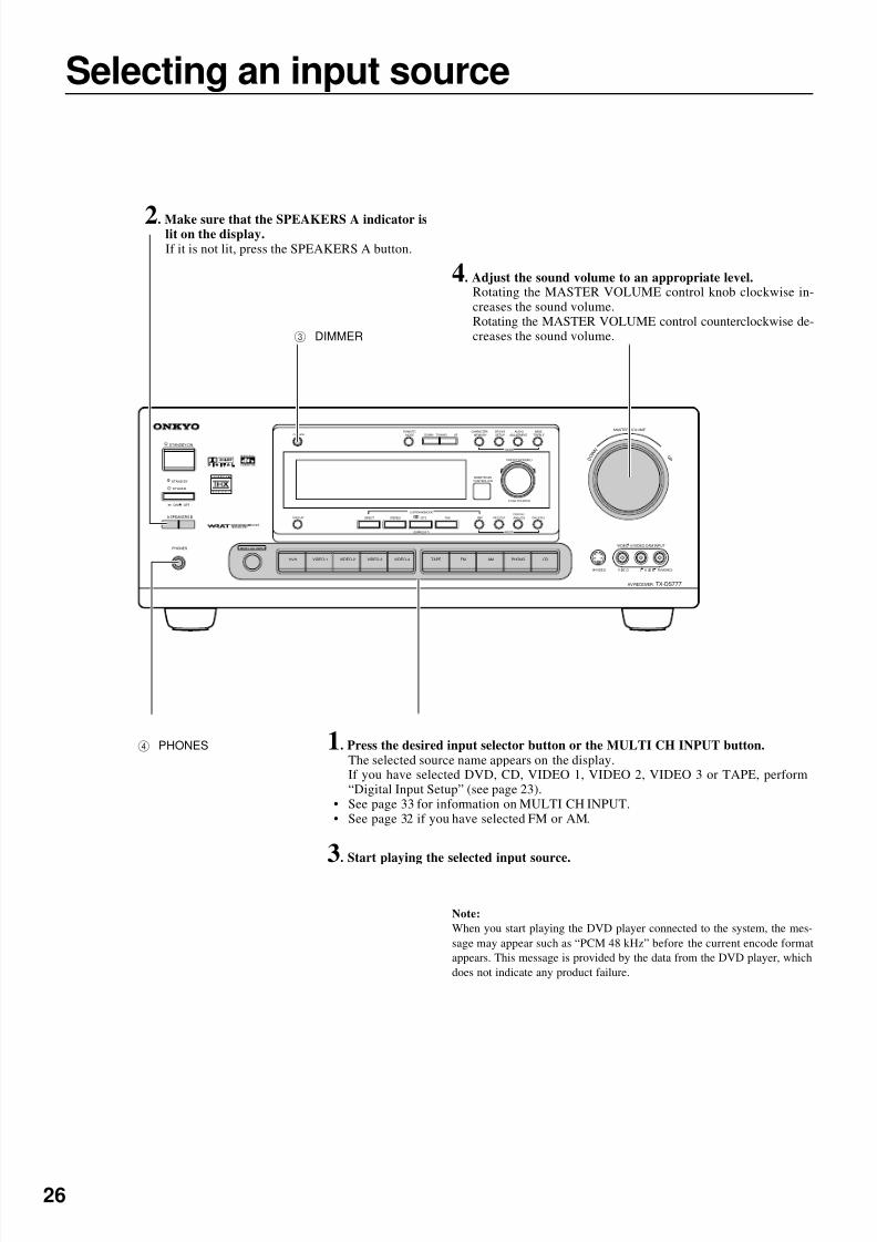
4 PHONES
2. Make sure that the SPEAKERS A indicator islit on the display.If it is not lit, press the SPEAKERS A button.
1. Press the desired input selector button or the MULTI CH INPUT button.The selected source name appears on the display.If you have selected DVD, CD, VIDEO 1, VIDEO 2, VIDEO 3 or TAPE, perform“Digital Input Setup” (see page 23).
• See page 33 for information on MULTI CH INPUT.• See page 32 if you have selected FM or AM.
3. Start playing the selected input source.
4. Adjust the sound volume to an appropriate level.Rotating the MASTER VOLUME control knob clockwise in-creases the sound volume.Rotating the MASTER VOLUME control counterclockwise de-creases the sound volume.3 DIMMER
Note:
When you start playing the DVD player connected to the system, the mes-sage may appear such as “PCM 48 kHz” before the current encode formatappears. This message is provided by the data from the DVD player, whichdoes not indicate any product failure.

8/7/2019 Onkyo TX-DS676
http://slidepdf.com/reader/full/onkyo-tx-ds676 27/64
27
** Input Selector **
Input = DVDOPTICAL 1
Digital Input SetupVideo Assign SetupIntelliVolume SetupListening Dolby
Mode= Pro LogicTHX Cinema
• Selecting an input source using the on-screendisplay
Instead of using the input selector buttons, you can use on-screen
display to select the desired input source.1. Press the OSD MENU button.2. Select “Input Selector” and then press the right edge of the
ENTER/Cursor button.3. Press the upper or lower edge of the ENTER/Cursor button
to select “Input” and then press the right or left edge of thebutton to select an input source.• When you select DVD, CD, VIDEO 1- 3, or TAPE, set the
digital input parameters on the Digital Input Setup screen.(See page 29.)
• When you have selected TUNER, the currently selected pre-set number is displayed on the next line.
• See page 33 for information on MULTICH INPUT.4. Press the center of the ENTER/Cursor button, or press the
EXIT button, to exit the setup mode.
3
Selecting an input source
If no sound is heard from the speakers, check thefollowing items:
• When you have selected DVD, CD, VIDEO 1- 3, or TAPE,check the “digital input setup” is correct. (See page 23.)
• Make sure that the input signal format setting is correct. (Seepage 28,29.)
• The Muting function may be activated. Cancel the Muting func-
tion. (See “Muting the sound” on page 31.)• Make sure that SPEAKERS A is selected. (See “Selecting thespeaker system” on page 30.)
Warning:
• Do not play CD-ROM discs that contain computer data as theymay damage the speakers when the sound is amplified by thereceiver.
2. SP A
1 SLEEP
2 MODE AUDIO
4. VOLUME ∆/ ∇
1. INPUT SELECTOR
3 DIMMER
1 This button allows you to set the sleep timer.(See page 31.)
2 Press this button to set the mode in which you can operate theTX-DS777/676.
3 Use this button to change the brightness of the display (normalor dim).For the European model, this button is not provided on the frontpanel. Change the display brightness using the remote control-
ler.4 You can connect stereo headphones to the PHONES jack using
a standard stereo plug.(When you connect headphones, the unit will enter STEREOmode automatically and no sound will be heard from the speakers.)

8/7/2019 Onkyo TX-DS676
http://slidepdf.com/reader/full/onkyo-tx-ds676 28/64
28
Setting the input signal format (Digital Input Setup)
The input signal format defaults to “Automatic.” Although you canuse this default setting normally, you may change it depending onthe input signal format.
Ex.) Setting the input signal format for DVD1. Press the DVD input selector button.2. Press the DIGITAL/ANALOG button twice to display the
digital input format.Press the SMART SCAN CONTROLLER.You are now able to select the input signal format.
3. By rotating the SMART SCAN CONTROLLER, select theinput signal format from among “Automatic,” “Digital,”“Analog,” “PCM,” and “DTS.”
Automatic (Automatic detection)Input signal format (Dolby Digital, DTS, MPEG, or PCM) usedin the selected input source is detected automatically to executethe required decoding process. If no digital signal is input, theinput signals to the analog input jacks will be played.
Digital (Digital input automatic detection)Input digital signal format (Dolby Digital, DTS, MPEG, orPCM) used in the selected digital input source is detected auto-matically to execute the necessary decoding process.
Analog (Analog audio signal processing)The audio signals input from the equipment connected to theanalog input jacks are played.
PCM (PCM signal processing)A decoding process is executed only when PCM signals are in-put.
DTS (DTS signal processing)
A decoding process is executed only when DTS signals are in-put.
Notes:• In “Automatic” or “Digital” mode, if the CD or LD is fast-for-
warded during playback, decoded PCM signals may produceskipped sound. In such cases, change the digital audio format to“PCM.”
• If a CD or LD encoded in the DTS format is played back using“PCM” or “Analog” mode, a noise will be produced. This noisecould damage the amplifier and speakers. Always use “Auto-matic”, “Digital”, or “ DTS” mode when playing back DTS-en-coded sources.
• MPEG signals can be detected only by models bearingmark on their front panel.
(TX-DS777: Other than U.S.A. and Canadian models)(TX-DS676: European model only)
4. Press the SMART SCAN CONTROLLER.This completes the digital audio format setup.
2DIGITAL/
ANALOG
3
Selecting an input source
PRESET/MODE ADJ
PUSH TO ENTER
PRESET/MODE ADJ
PUSH TO ENTER
4 PRESET/MODE ADJ
PUSH TO ENTER
SPEAKERS
A
TUNED
AUTO
SPEAKERS
A
TUNED
AUTO
SPEAKERS
A
TUNED
AUTO
1V ID EO-1 V ID EO-2 V ID EO-3 V ID EO-4DVD FM AM PHONO C DTAPE

8/7/2019 Onkyo TX-DS676
http://slidepdf.com/reader/full/onkyo-tx-ds676 29/64
29
* Digital Input Setup *
CD :COAXIAL 1Automatic
DVD :COAXIAL 2Automatic
VIDEO 1 :----Automatic
• Using the on-screen display
1. Press the OSD MENU button.2. Select “Input Selector” and then press the right edge of the
ENTER/Cursor button.3. Select “Digital Input Setup” and then press the right edge of
the ENTER/Cursor button.
The “Digital Input Setup” screen appears. To display VIDEO 2and later items, press the lower edge of the ENTER/Cursor but-ton.• Select the digital input connector from among “OPTICAL 1,”
“OPTICAL 2,” “COAXIAL 1,” “COAXIAL 2,” and“– – – –.”
• If no digital input connector is assigned to the selected inputsource, it will be indicated as “– – – –.”
• To enter the setting, move the cursor vertically using the EN-TER/Cursor button.
4. To set the input signal format, move the cursor to the lineimmediately below the input source and then press the rightor left edge of the ENTER/Cursor button.• Select the digital audio format from among “Automatic,”
“Digital,” “Analog,” “PCM,” and “DTS.”• Holding down the right or left edge of the ENTER/Cursor
button sequentially changes the setting.5. Press the center of the ENTER/Cursor button, or press the
EXIT button, to exit the setup mode.
Notes on DTS1. If you play a CD or LD that supports DTS when the “Analog” or
“PCM” setting is selected on the TX-DS777/676, the DTS en-coded signal will not be decoded and noise will be output. Thisnoise could damage the amplifier and speakers. Therefore, besure to select “Automatic”, “Digital” or “DTS” and use the digi-tal input jacks (OPTICAL1/2 /COAXIAL1/2) to connect theDTS source.
2. If you play a CD or LD that supports DTS when the “Auto-
matic”, or “Digital” setting is selected, you may hear a noise fora short while until the DTS decoder recognizes the DTS en-coded signal and starts operating. This is not a malfunction.
3. If you press the PAUSE or SKIP button on the player whileplaying a DTS source, a short noise may be heard. This is not amalfunction. In such cases, try playing the source in the “DTS”mode.
4. The DTS indicator on the TX-DS777/676 lights up while itplays the DTS source. When playback concludes and the DTSsignal transmission stops, the TX-DS777/676 remains in DTSmode and the DTS indicator remains lit. This prevents noisewhen you operate the PAUSE or SKIP button on the player.Therefore, if the source switches from the DTS signal to thePCM signal immediately, the PCM signal may not be played. Inthis case, stop the playback of the source on the player for about
three seconds, then resume playback.5. Some CD players and LD players may be unable to play DTSsources correctly even if you connect the player to the TX-DS777/676 digitally. This is because the digital signal has beenprocessed (such as the output level, sampling frequency, fre-quency response, etc.), and the TX-DS777/676 cannot recog-nize the signal as DTS data. Therefore, you may hear noisewhen you play a DTS source while processing the signal.
6. The OUT jacks of the VIDEO-1, VIDEO-2, and TAPE connec-tors output analog audio signals. Do not record CDs or LDs thatsupport DTS using these jacks. Otherwise, you will record aDTS-encoded signal as noise.
Selecting an input source

8/7/2019 Onkyo TX-DS676
http://slidepdf.com/reader/full/onkyo-tx-ds676 30/64

8/7/2019 Onkyo TX-DS676
http://slidepdf.com/reader/full/onkyo-tx-ds676 31/64
31
Selecting an input source
Falling asleep with music (Sleep function,remote controller only)
You can turn off the power to the TX-DS777/676 automatically af-ter a specified time period.1. Press the MODE AUDIO button.2. Press the SLEEP button.
The display shows “Sleep 90min,” which means the receiverautomatically enters the standby mode after 90 minutes.
3. Press the SLEEP button repeatedly until the desired sleeptime is displayed.Each time you press this button, the time decreases by 10 min-utes.
To check how much time is left before the unit turns off...Press the SLEEP button when the Sleep function is enabled.
Note:Pressing the SLEEP button when the Sleep time display shows 10
minutes or less cancels the Sleep function.Adjusting the tone (Bass and treble adjustment)
The bass and treble levels can be adjusted in the range of +/-12 inunits of 2.You cannot perform this adjustment when the listening mode is“THX” or “Direct.”1. Press the BASS/TREBLE button.
The display shows "Bass=."Rotate the SMART SCAN CONTROLLER to adjust the basslevel.
2. Press the SMART SCAN CONTROLLER.The display shows "Treble=."Rotate the SMART SCAN CONTROLLER to adjust the treble
level.3. Press the SMART SCAN CONTROLLER.
• Adjusting the bass and treble levels with the on-screen display
1. Press the OSD MENU button.2. Select "Listening mode Setup" and then press the right edge
of the ENTER/Cursor button.3. Select "Listening Mode" and then press the right edge of the
ENTER/Cursor button4. Select "Tone Control" and then press the right edge of the
ENTER/Cursor button.The "Tone Control Setup" screen appears.Press the upper or lower edge of the ENTER/Cursor button toselect "Bass" or "Treble" and then press the right or left edge of
the button to adjust the bass or treble level.Select “Set to Flat” and then press the right edge of the ENTER/ Cursor button to restore the “flat” bass and treble sound.
5. Press the center of the ENTER/Cursor button, or press theEXIT button, to exit the setup mode.
Note:You cannot perform this adjustment when the listening mode is “Di-rect” or “THX (TX-DS777 only).”
4
* Tone Control *
Bass = 0Treble = +2
Set To Flat
BASS/ TREBLE
Remote controller
SPEAKERS
A
SLEEP
AUTO
STEREO
Muting the sound (Muting function, remotecontroller only)
Use this function to turn off the playback sound immediately. Forexample, you can use it when you receive a phone call when listen-ing to music.
Press the MUTING button.The display shows "Muting." Now the sound output to the speakersand headphones stops.
Press the MUTING button again to turn on the sound output.
Note:The Muting function will be canceled automatically if the receiveris set in the standby mode.
Remote controller

8/7/2019 Onkyo TX-DS676
http://slidepdf.com/reader/full/onkyo-tx-ds676 32/64
32
Selecting a preset station
MASTER VOLUME
STANDBY/ON
PHONESVIDEO CAM INPUT/ 4VIDEO
V ID EO A UD IOL R(MONO)S VIDEO
STAND-BY
AV RECEIVER TX-DS777
POWER
OFFON
A SPEAKERS B
TI CH INPUTMUL
FM AM PHONO C DTAPEVIDEO-1DVD VIDEO-4VIDEO-3VIDEO-2
DOWN
U P
FM MUTE/
MODE
CHARACTER/
MEMORY
SP/SYS
SETUP
SMART SCAN
CONTROLLER
MODE
AUDIO
ADJUSTMENT
BASS/
TREBLE
DISPLAY DSP REC OUT
PRESET/MODE ADJ
PUSH TO ENTER
DOWN TUNING UP
THX/DTS
SURROUND MODE
LISTENING MODE
STEREODIRECTDIGITAL/
ANALOG CH LEVEL
DIMMER
1. Press the AM or FM button.
2. Rotate the SMART SCAN CONTROLLER.
1. Press the MODE AUDIO button and thenthe TUNER button.
• Using the on-screen display
1. Press the OSD MENU button.2. Select “Input Selector” and then press the right edge of the
ENTER/Cursor button.3. Select “Input” and then press the right or left edge of the
ENTER/Cursor button to select “TUNER.”4. Select “Preset No.” and then press the right edge of the EN-
TER/Cursor button5. Press the right or left edge of the ENTER/Cursor button to
select the desired preset number.6. Press the center of the ENTER/Cursor button, or press the
EXIT button. The on-screen display disappears.
* Preset Station *
Preset No. = 3
1:---- 6: 5312:---- 7:----
3:87.60 8:----4:---- 9:----5:---- 10:----
** Input Selector **
Input = TUNERPresent No. =3
Video Assign SetupIntelliVolume SetupListening
Mode= Orchestra
3,4
5
2. Press the CH (+ or -) button to select the de-sired preset number.

8/7/2019 Onkyo TX-DS676
http://slidepdf.com/reader/full/onkyo-tx-ds676 33/64
33
1
3
Playing a multichannel input source
• Using the on-screen display
1. Press the OSD MENU button.2. Select “Input Selector” and press the right edge of the EN-
TER/Cursor button.3. Press the right or left edge of the ENTER/Cursor button to
select “MULTI CH.” Then, press the center of the ENTER/ Cursor button.The “Multi Ch Input” screen appears.
4. If you wish to skip assigning a video source, proceed to step 5.To assign a video source, select “Video Assign Setup” and thenpress the right edge of the ENTER/Cursor button. When “VideoAssign Setup” screen appears, move the cursor (which is alreadylocated at “MULTI CH”) rightward or leftward to select thevideo source you wish to assign. When selected, press the centerof the ENTER/Cursor button to return to the previous screen.
5. Select “Level Setup” and press the right edge of the ENTER/ Cursor button."Multi Ch Input Level Setup" screen appears.
6. Press the upper or lower edge of the ENTER/Cursor buttonto select the item. Then, press the right or left edge of thebutton to select the desired parameter.At the listening position, adjust the speaker output level so thatyou can hear the same sound volume from all speakers. For theright front, left front, center, right surround and left surroundspeakers, the output levels can be adjusted within the range of -12 dB/+12 dB. The adjustment range of the subwoofer, how-
ever, is -30 to +10 dB.7. Press the center of the ENTER/Cursor button, or press the
EXIT button, to exit the setup mode.
MULTI CH INPUT
** Multi Ch Input **
Level Setup
Left = 0dB
Center = +5dBRight = 0dBLeft Sur = 0dBLeft Sur = 0dBSubwoofer =+10dB
3
3
Remote controller
Setting the MULTI CHANNEL INPUT
To play back an input source you connected with the MULTICHANNEL INPUT connectors, you must set the output level of each speaker. Also, note that this output level setting must be per-formed independent of the speaker levels you set using the test tone
(see page 21).Before playing movie soundtracks etc. in the multichannel inputmode, check again that the source is connected properly(see page 9).1. Press the MULTI CH INPUT button.
If you wish to assign a video source to the multichannel inputsource, perform the following setting. If you do not wish to doso, proceed to step 3.1. Press the SP/SYS SETUP button repeatedly until “Video As-sign?” appears and then press the SMART SCAN CONTROL-LER.2. Rotate the SMART SCAN CONTROLLER to select thevideo source you wish to assign and then press the SMARTSCAN CONTROLLER.
2. Start playing the component connected to the MULTI
CHANNEL INPUT connectors.3. Press the CH SEL button on the remote controller to select
the speaker. Then, press the LEVEL (+ or -) button to adjustthe output level.At the listening position, adjust the speaker output level so thatyou can hear the same sound volume from all speakers. For theright front, left front, center, right surround and left surroundspeakers, the output levels can be adjusted within the range be-tween -12dB ~ +12 dB. The adjustment range of the subwoofer,however, is -30 to +10 dB.
Using the front panel1. Press the CH LEVEL button.2. Rotate the SMART SCAN CONTROLLER to select the output
level.
Repeat the above steps until you set the output levels for allspeakers.
6

8/7/2019 Onkyo TX-DS676
http://slidepdf.com/reader/full/onkyo-tx-ds676 34/64
34
Using the Listening Modes
Listening Modes
The TX-DS777/676’s surround sound enables you to enjoy the pres-ence of a movie theater or concert hall in your room.Before using a listening mode, make sure the Speaker Setup param-
eters have been set (refer to page 18 ~ 23). Once the parameters havebeen set, it is not necessary to set them again.The configuration of the speakers are very important for the sur-round sound. Refer to “connecting speakers” on page 10.
DOLBY DIGITAL Surround,DTS (Digital Theater System), MPEG Surround
This 5.1-channel digital surround format enables you to individu-ally record and play five full-range (20Hz–20kHz) channels (leftand right front, center, two surround channels) plus an LFE channel(Low Frequency Effect) for the low-range effect sound. It will cre-ate a realistic sound that could be heard in the theaters and concerthalls.DOLBY DIGITAL: Select this option when you play a DVD videothat has a mark.DTS: Select this option when you play a DVD player, video disc, orCD that has a mark.MPEG(European model only):Select this option when you play aDVD video that has a mark.
DOLBY PRO LOGIC Surround
This surround format consists of four channels (left and right front,center, and monaural surround channels) and emphasizes the centerchannel. This format is very effective for panning music, conversa-tion, and three-dimensional sound movement output from threefront channels. It also simulates the atmosphere and surround ef-fects of the sound reflected from the side and rear walls of the the-ater. Select this option when you play a VHS, VHS Hi-Fi, laserdisc, or DVD video that has a mark.
Home THX Cinema Surround(TX-DS777 only)DOLBY DIGITAL/DTS/DOLBY PRO LOGIC/MPEG THX CINEMAIn these modes, Dolby Digital/Dolby Pro Logic/DTS or MPEGSurround is reprocessed using a technique called “Home THX pro-cessing.” Home THX processing was developed by the surround en-gineers at Lucasfilm Ltd. for accurate reproduction of soundfields inthe home environment as the filmmaker intended, equivalent tothose obtained in a well-furnished movie theater. For Home THXCinema Surround playback, we recommend that you use a THXspeaker system certified by Lucasfilm Ltd. (such as Onkyo's THXspeaker system HTS SYSTEM-2).
Surround modes incorporating Onkyo's originalSurround processing
Surround mode suitable for movie soundtracks
In the following surround modes, additional processing is applied tothe Dolby Digital/Dolby Pro Logic/DTS/MPEG Surround.ACTIONSuitable for movie soundtracks involving a lot of special effectsounds.MUSICALSuitable for musical film soundtracks, where importance is placedon the music, environmental sound, and front image.
Onkyo’s listening modes
MONO MOVIE(TX-DS777 only) : This mode is suitable for playback monaural recordings such as old movie soundtracks. Thecenter channel delivers unprocessed original sound, whereas theother channels delivers processed center-channel sound withappropriate reverberation. Thus, you can enjoy monaural sound
with the atmosphere of a movie theater.ORCHESTRA : This mode is suitable for classics and opera music.
The center channel is cut and the surround channels are empha-sized to widen the stereo image. It will simulate a natural rever-beration that can be created in a large hall.
UNPLUGGED : This mode is suitable for acoustic instrumental
Before Using Listening Mode
sounds, vocals, and jazz music. By emphasizing the front stereoimage, it will simulate the acoustics in front of the stage.
STUDIO-MIX : This mode is suitable for rock and popular music.Lively sounds with a powerful acoustic image will make you
feel as if you are in a club.5CH STEREO : This mode is useful for background music. Thefront and surround channels will create a stereo image.
TV LOGIC : This mode offers a realistic acoustics of a TV pro-gram being aired in the TV studio. It enhances the entire sur-round sound and clarity of conversation.
DIRECT : This mode delivers pure sound with the minimum soundquality adjustment and filtration. To attain it, the sound recordedfor the Right and Left front channels is output to the Right andLeft front speakers only and not output to the subwoofer.
STEREOSelect this mode when you do not wish to use the surroundmode. All input sound is output from the front speakers.
DSP (Digital Signal Processor)
The DSP converts the audio signals into digital audio format to cre-ate sound reflection. This yields an effect that makes you feel likelistening to a live performance.The following illustration shows how reflected sound reaches theaudience in a concert hall. Onkyo's DSP and advanced technologieslet you get such a sound reflection effect from the unit.
Note:The concert hall effect is produced from the reflections and rever-
berations contained in the original recording. These are convertedinto reflected sound that is reproduced from four directions. Thus, insome cases an unnatural impression can be conveyed if there are toofew reflections in the recording or if the effects in the original re-cording were produced artificially.
Example: Sound reflection in a concert hall
• A system with L/R front and center speakersThe following modes are available:
DOLBY 3 STEREOThe surround channel sound is output from the left and rightfront speakers.STEREOThis is a normal stereo mode. Surround mode is cancelled.DIRECTSee the description above.
• A system with L/R front speakersThe following mode is available:
STEREOThis is a normal stereo mode.DIRECT
See the description above.
Stage
reflections
Ceiling reflections
Wall
reflections
Wall reflections
Direct sound

8/7/2019 Onkyo TX-DS676
http://slidepdf.com/reader/full/onkyo-tx-ds676 35/64
35
Using the listening modes
1. Press one of the INPUT SELECTOR buttons to select the desiredsound source.
MASTER VOLUME
STANDBY/ON
PHONESVIDEO CAM INPUT/ 4VIDEO
V ID EO A UD IOL R(MONO)S VIDEO
STAND-BY
AV RECEIVER TX-DS777
POWER
OFFON
A SPEAKERS B
TI CH INPUTMUL
FM AM PHONO C DTAPEVIDEO-1DVD VIDEO-4VIDEO-3VIDEO-2
DOWN
U P
FM MUTE/
MODE
CHARACTER/
MEMORY
SP/SYS
SETUP
SMART SCAN
CONTROLLER
MODE
AUDIO
ADJUSTMENT
BASS/
TREBLE
DISPLAY DSP REC OUT
PRESET/MODE ADJ
PUSH TO ENTER
DOWN TUNING UP
THX/DTS
SURROUND MODE
LISTENING MODE
STEREODIRECTDIGITAL/
ANALOG CH LEVEL
DIMMER
3. MASTER VOLUMEcontrol knob2. Use the LISTENING MODE buttons to select
the desired listening mode and then start play-ing the selected source.
Use these buttons to setthe listening mode param-
eters. (See page 38.)
1. Input selector buttonsSelect the desired input source.To change the input source using the remote controller,press the MODE AUDIO button before pressing the inputselector button.
3. VOLUME buttonsUse these buttons to adjust the sound volume.
2. Listening mode buttonUse these buttons to select the desired listening mode andthen start playing the selected source.

8/7/2019 Onkyo TX-DS676
http://slidepdf.com/reader/full/onkyo-tx-ds676 36/64
36
Using the listening modes
Pressing the DSP button and then rotating the SMART SCANCONTROLLER lets you view all the listening modes. You can se-lect directly from four listening modes. The mode you can selectmay vary depending on where the unit is purchased.
DIRECT : Press this button if you wish to enjoy pure directsound.
STEREO : Press this button to listen to a normal stereo audio./DTS/MPEG( /DTS) : Press this button when you wish
to play Dolby ProLogic, Dolby Digital, DTS Surround, (orMPEG) software.
5CH STEREO(TX-DS676) : Press this button to play 5-ch ste-reo sound (see the previous page).
THX(TX-DS777) : Press this button when THX speakers areused.
Notes:• To play a Dolby digital/DTS or MPEG Surround source, you
need to connect the sound source with a correct digital input
connector.• When you play the Dolby digital/DTS or MPEG Surroundsource, the receiver automatically enters Dolby Digital Sur-round (stereo)/DTS or MPEG Surround (stereo) mode respec-tively.
THXMovies which have been encoded in Dolby Digital, DTS, MPEGand Dolby Pro Logic can all benefit by activating the THX mode.THX should be activated only when watching movies which weremixed for playback in large movie theatre environments. THX neednot be activated for music, movies that were made especially fortelevision or shows such as sports programming, talk shows, etc.This is because they were mixed in a small room environment.
Dial normDialogue Normalization (Dial Norm) is a feature of Dolby Digital.When playing back software which has been encoded in DolbyDigital, sometimes you may see a brief message in the front paneldisplay which will read Dial Norm XdB (X being a numeric value).Dialogue Normalization serves to let you know if the source mate-rial has been recorded at a higher or lower level than usual. Forexample, if you see the following message: Dial Norm +4dB in thefront panel display, to keep the overall output level constant justturn down the volume control by 4dB. In other words, the sourcematerial that you are listening to has been recorded 4dB louder thanusual. If you do not see a message, then no adjustment of the volumecontrol is necessary.
DSPTHX/DTS
LISTENING MODE
STEREODIRECT
SURROUND
DSPTHX
LISTENING MODE
STEREODIRECT /DTS/MPEG
SURROUND
The LISTENING MODE button names on the unit may vary depending on
the model.
Using the listening modes
TX-DS777 USA&Canadian model
TX-DS777 Others
TX-DS676 European model
TX-DS 676 Others
DSP5CH STEREO
LISTENING MODE
STEREODIRECT /DTS/MPEG
SURROUND
DSP5CH STEREO
LISTENING MODE
STEREODIRECT /DTS
SURROUND
** Input Selector **
Input = DVDOPTICAL 1
Digital Input SetupVideo Assign SetupIntelliVolume SetupListening Dolby
Mode= Pro LogicTHX Cinema
• Selecting an Listening mode using the on-screendisplay
Instead of using the Listening mode buttons, you can use on-screendisplay to select the desired input source.1. Press the OSD MENU button.2. Select “Input Selector” and then press the right edge of the
ENTER/Cursor button.3. Press the upper or lower edge of the ENTER/Cursor button
to select “Listening mode” and then press the right or leftedge of the button to select an listening mode.
4. Press the center of the ENTER/Cursor button, or press theEXIT button, to exit the setup mode.
3
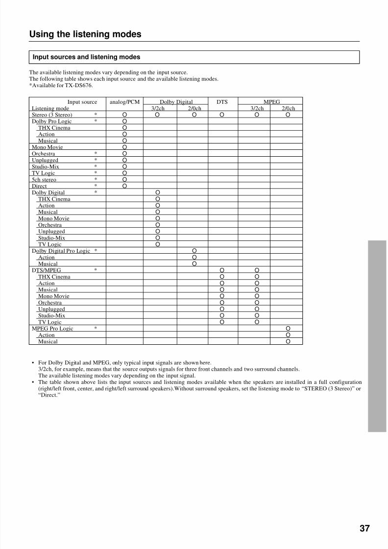
8/7/2019 Onkyo TX-DS676
http://slidepdf.com/reader/full/onkyo-tx-ds676 37/64
37
Input sources and listening modes
The available listening modes vary depending on the input source.The following table shows each input source and the available listening modes.*Available for TX-DS676.
Using the listening modes
• For Dolby Digital and MPEG, only typical input signals are shown here.3/2ch, for example, means that the source outputs signals for three front channels and two surround channels.The available listening modes vary depending on the input signal.
• The table shown above lists the input sources and listening modes available when the speakers are installed in a full configuration(right/left front, center, and right/left surround speakers).Without surround speakers, set the listening mode to “STEREO (3 Stereo)” or“Direct.”
Input source analog/PCM Dolby Digital DTS MPEGListening mode 3/2ch 2/0ch 3/2ch 2/0chStereo (3 Stereo) * O O O O O O
Dolby Pro Logic * O
THX Cinema O
Action O
Musical O
Mono Movie O
Orchestra * O
Unplugged * O
Studio-Mix * O
TV Logic * O
5ch stereo * O
Direct * O
Dolby Digital * OTHX Cinema O
Action O
Musical O
Mono Movie O
Orchestra O
Unplugged O
Studio-Mix O
TV Logic O
Dolby Digital Pro Logic * O
Action O
Musical O
DTS/MPEG * O O
THX Cinema O O
Action O O
Musical O OMono Movie O O
Orchestra O O
Unplugged O O
Studio-Mix O O
TV Logic O O
MPEG Pro Logic * O
Action O
Musical O

8/7/2019 Onkyo TX-DS676
http://slidepdf.com/reader/full/onkyo-tx-ds676 38/64
38
Parameter Re-EQ* LateNight* LFE level* Front Effect* Reflect Level* Reverb Level Room SizeListening modeStereo(3 Stereo) *Dolby Pro Logic * O
THX Cinema O
Action/Musical O O O O O
Mono Movie O O O O O
Orchestra/Unplugged/ * O O O O O
Studio-Mix/TV Logic5ch Stereo *Direct *
Dolby Digital * O O OTHX Cinema O O O
Action/Musical O O O O O O O
Mono Movie/Orchestra/ Unplugged/Studio-Mix/ O O O O O O O
TV LogicDolby Digital Pro Logic * O O O
Action/Musical O O O O O O O
DTS/MPEG * O O
THX Cinema O O
Action/Musical O O O O O O
Mono Movie/Orchestra/ Unplugged/Studio-Mix/ O O O O O O
TV LogicMPEG Pro Logic * O O
Action/Musical O O O O O O
Setting the listening mode parameters
How to set the listening mode parameters
To set the listening mode parameters, you first press the AUDIOADJUSTMENT button to select the item and then rotate theSMART SCAN CONTROLLER to select the parameter.1. Select the listening mode for which you wish set parameters.
2. Press the AUDIO ADJUSTMENT button until“Frt Effect=...” appears.The parameters you can set vary depending on the selected lis-tening mode. You can press this button to display the availableparameters one by one.
3. Rotate the SMART SCAN CONTROLLER to change theparameter setting.
4. Press the SMART SCAN CONTROLLER.
2
3
AUDIOADJUSTMENT
** Listening Mode **
SetupListening
Mode=Mono Movie
Front Effect = ONReflect Level = 0dBReverb Level = 0dBRoom Size =Mid
Default
• Using the on-screen display
If you use the on-screen display to set a listening mode, you can setthe relevant parameters on the same screen.
1. Press the OSD MENU button.2. Select the “Listening Mode” and press the right edge of the
ENTER/Cursor button.3. Press the upper or lower edge of the ENTER/Cursor button
to select “Listening Mode.”Then, press the right or left edge of the button to select the lis-
tening mode.The parameter items available for the selected listening modeare displayed.
4. Press the upper or lower edge of the ENTER/Cursor buttonto select the item and then press the right or left edge of thebutton to set a value.If you select “LFE Level,” “Setup,” etc., an additional screenwill appear. Set the value for each item in the similar manner.
5. Press the center of the ENTER/Cursor button, or the EXITRETURN button, to exit the setup mode.
Default: Select “Default” to reset each parameter to the factory-setdefault.
*Available for TX-DS676.(The detailed information on the listening mode parameters is provided on the next page.)
1
PRESET/MODE ADJ
PUSH TO ENTER
PRESET/MODE ADJ
PUSH TO ENTER
SPEAKERS
A
DSP
DSPTHX/DTS
LISTENING MODE
STEREODIRECT
SURROUND

8/7/2019 Onkyo TX-DS676
http://slidepdf.com/reader/full/onkyo-tx-ds676 39/64
39
Setting the listening mode parameters
Listening mode parameters
• Re-EQ (Cinema Re-Equalization)
Select “ON” or “OFF.”
The Re-EQ function is effective except for “5CH STEREO” and“DIRECT.”Re-Equalization takes the edginess or “brightness” out of yourhome cinema sound, compensating for the fact that sound mixed fortheaters will sound too bright when played back through speakers inthe home environment.
• Late Night
Select “High,” “Low,” or “OFF.”
Cinema sound has a vast dynamic range and therefore, to hear quietsound such as environmental sound and human conversations, it
must be played back at large sound volumes. When this parameter isset to “High” or “Low,” however, the dynamic range of the sound isnarrowed down to allow you to hear easily minute sound at low vol-umes. This function is useful if you wish to play a movie at lowvolumes, especially in midnight.
Notes:• The depth of the Late Night effect is determined by Dolby Digi-
tal software. Some sounds may produce no or little effect.• The Late Night function is effective only on Dolby Digital en-
coded software.
• LFE (Low Frequency Effect) level
This parameter is used to adjust the level of LFE in Dolby Digital,(MPEG,) or DTS software. When this parameter is selected, the fol-lowing screen appears.
Note:• The LFE level setting is effective only on Dolby Digital, DTS,
or MPEG software.With some software, this setting may produce no effect.
• The MPEG setting is possible only in limited regions.
• Front Effect
Select “ON” or “OFF.”
Some live recordings contain acoustic reverberation. When youplay these sources, more reverberation will be applied by the DSP,creating too much reverb effects and the sound loses its frame or
presence. In this case, set FRONT EFFECT to OFF. No reverbera-tion from the DSP will be applied to the sound output from threefront channels, and the sound source will be played as it is withoutany further reverberation.
Note:
The Front Effect function is effective only on the Action, Musical,MonoMovie, Orchestra, Unplugged, Studio-Mix, and TV Logic sound.
• Reflect Level
Set a value between -5 and +5 dB, in units of 1 dB.
You can adjust the strength of direct sound reflection, depending on
the playback source material, your audio room conditions, and soon.
• Reverb Level (TX-DS777 only)
Set a value between -5 and +5 dB, in units of 1 dB.
Adjust the depth of acoustic reverberation, depending on the play-back source material, your audio room conditions, and so on.
• Room Size (TX-DS777 only)
Set “Large,” “Mid,” or “Small.”
Change the virtual hall size set for each surround mode.
1. Adjust this parameter when the source is “Dolby Digital.”Select “-∞ dB,” “-20dB,” “-10dB,” “or “0dB.”The recommended setting is “0dB.”
2. Adjust this parameter when the source is “DTS” and thesurround mode is “DTS.”Select “-∞ dB,” “-20dB,” “0dB,” or “+10dB.”The recommended setting is “+10dB.”
3. Adjust this parameter when the source is “DTS” and the lis-tening mode is “DTS Action,” “DTS Musical,” “DTS THX,”
or “DTS Mono Movie.”Select “-∞ dB,” “-20dB,” “-10dB,” or “0dB.”The recommended setting is “0dB.”
4. Adjust this parameter when the source is “DTS” and the lis-tening mode is “DTS Orchestra,” “DTS Unplugged,” “DTSStudio-Mix,” or “DTS TV Logic.”
Select “-∞ dB,” “-10dB,” “0dB,” or “+10dB.”The recommended setting is “+10dB.”
5. Adjust this parameter when the source is “MPEG” and thesurround mode is “MPEG.”Select “-∞ dB,” “-20dB,” “0dB,” or “+10dB.”The recommended setting is “+10dB.”
6. Adjust this parameter when the source is “MPEG” and thelistening mode is “MPEG Action,” “MPEG Musical,”“MPEG THX,” or “MPEG Mono Movie.”Select “-∞ dB,” “-20dB,” “-10dB,” or “0dB.”The recommended setting is “0dB.”
7. Adjust this parameter when the source is “MPEG” and thelistening mode is “MPEG Orchestra,” “MPEG Unplugged,”“MPEG Studio-Mix,” or “MPEG TV Logic.”Select “-∞ dB,” “-10dB,” “0dB,” or “+10dB.”The recommended setting is “+10dB.”
* LFE Level Setup *
Dolby Digital :0dBDTS :0dBCinema Group :0dBMusic Group :0dBMPEG :0dBCinema Group :0dB
Music Group :0dB
*5,6, and7 are provided for European model only.

8/7/2019 Onkyo TX-DS676
http://slidepdf.com/reader/full/onkyo-tx-ds676 40/64
40
Assigning a video source to each audioinput source
Assigning a video source to each audio inputsource (video Assign Setup)
You can assign a video source to audio input sources such as CD. Bydoing so, you can play a CD or other audio source while showing theassigned video images on the TV.1. Select the desired audio input source by pressing the corre-
sponding input selector button.2. Press the SP/SYS SETUP button repeatedly until "Video
Assign?" is displayed. Then Press the SMART SCAN CON-TROLLER.The video assign mode has been set.
3. Rotate the SMART SCAN CONTROLLER to select thevideo source you wish to assign.You can select one from 6 video sources, DVD, VIDEO 1,VIDEO 2, VIDEO 3, VIDEO 4, and ---- (None).Press the SMART SCAN CONTROLLER.
3
1
• Using the on-screen display
1. Press the OSD MENU button.2. Select “Input Selector” and then press the right edge of the
ENTER/Cursor button.3. Select “Video Assign Setup” and then press the right edge of
the ENTER/Cursor button.“Video Assign Setup” screen is displayed.When the cursor is on “TAPE,” you can press the lower edge of the ENTER/Cursor button to display additional items.When the cursor is on “DVD,” you can press the upper edge of the ENTER/Cursor button to display the previous items.
4. Press the upper or lower edge of the ENTER/Cursor buttonto select the audio input source and then press the right orleft edge of the button to assign a video source.You can select one from 6 video sources, DVD, VIDEO 1,VIDEO 2, VIDEO 3, VIDEO 4, and ---- (None).
5. Press the center of the ENTER/Cursor button, or press theEXIT button, to exit the setup mode.
* Video Assign Setup *
CD :----PHONO :----FM :----AM :----TAPE :----
* Video Assign Setup *
DVD :DVDVIDEO 1 :VIDEO 1VIDEO 2 :VIDEO 2VIDEO 3 :VIDEO 3VIDEO 4 :VIDEO 4
MULTI CH:----
SP/SYS
SETUP
PRESET/MODE ADJ
PUSH TO ENTER
2
VIDEO-1 V IDEO-2 V IDEO-3 V IDEO-4DVD FM AM PHONO C DTAPE
PRESET/MODE ADJ
PUSH TO ENTER
PRESET/MODE ADJ
PUSH TO ENTER
SPEAKERS
A
DSP
SPEAKERS
A
DSP
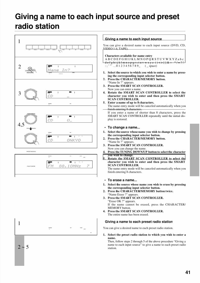
8/7/2019 Onkyo TX-DS676
http://slidepdf.com/reader/full/onkyo-tx-ds676 41/64
41
Giving a name to each input source
You can give a desired name to each input source (DVD, CD,
VIDEO 1-4, TAPE).
Characters available for name entryA B C D E F G H I J K L M N O P Q R S T U V W X Y Z a b cd e f g h i j k l m n o p q r s t u v w x y z ( ) < > [ ] & + - * / = ? !: ; ’ ” . , 0 1 2 3 4 5 6 7 8 9 _ ( _ space)
1. Select the source to which you wish to enter a name by press-ing the corresponding input selector button.
2. Press the CHARACTER/MEMORY button.“Name In ?” appears.
3. Press the SMART SCAN CONTROLLER.Now you can enter a name.
4. Rotate the SMART SCAN CONTROLLER to select thecharacter you wish to enter and then press the SMART
SCAN CONTROLLER.5. Enter a name of up to 8 characters.
The name entry mode will be canceled automatically when youfinish entering 8 characters.If you enter a name of shorter than 8 characters, press theSMART SCAN CONTROLLER repeatedly until the initial dis-play is restored.
• To change a name...
1. Select the source whose name you wish to change by pressingthe corresponding input selector button.
2. Press the CHARACTER/MEMORY button.“Name In ?” appears.
3. Press the SMART SCAN CONTROLLER.
Now you can change the name.4. Press the TUNING DOWN/UP button to select the character
you wish to change.5. Rotate the SMART SCAN CONTROLLER to select the
character you wish to enter and then press the SMARTSCAN CONTROLLER.The name entry mode will be canceled automatically when youfinish entering 8 characters.
• To erase a name...
1. Select the source whose name you wish to erase by pressingthe corresponding input selector button.
2. Press the CHARACTER/MEMORY button twice.“Name Erase ?” appears.
3. Press the SMART SCAN CONTROLLER.“Erase OK ?” appears.If the name cannot be erased, press the CHARACTER/ MEMORY button.
4. Press the SMART SCAN CONTROLLER.The entire name has been erased.
Giving a name to each input source and preset
radio station
SPEAKERS
A PCM DIGITAL
STEREO
VIDEO-1 V IDEO-2 V IDEO-3 V IDEO-4DVD FM AM PHONO C DTAPE
3
CHARACTER/
MEMORY
4,5
1
PRESET/MODE ADJ
PUSH TO ENTER
2
PRESET/MODE ADJ
PUSH TO ENTER
PRESET/MODE ADJ
PUSH TO ENTER
1 Giving a name to each preset radio station
You can give a desired name to each preset radio station.
1. Select the preset radio station to which you wish to enter aname.Then, follow steps 2 through 5 of the above procedure “Giving aname to each input source” to give a name to each preset radio
station.
SPEAKERS
A
DSP
AUTO
TUNED
ch
SPEAKERS
A
DSP
SPEAKERS
A
DSP
SPEAKERS
A
DSP
AUTO
TUNED
2 ~ 5

8/7/2019 Onkyo TX-DS676
http://slidepdf.com/reader/full/onkyo-tx-ds676 42/64
42
Adjusting the output level of each speakerwhile listening to it
Fine-tuning the output level of each speaker
You can fine-tune the output level of each speaker according to your
taste.The output levels you set as below will be lost once the unit is in stand-bymode. (The speaker levels you set using the test tone will be restored.)1. Press the CH LEVEL button.
The output level of the Left front speaker is displayed.2. Rotate the SMART SCAN CONTROLLER to select the out-
put level and then press the SMART SCAN CONTROL-LER.You can now adjust the output level of the center speaker.
3. Repeat the operation described in step 2.Set the speaker level of each speaker in the following sequence:Left (Left front) Center Right (Right front) R-sur (Rightsurround) L-sur (Left surround) Subwoofer (Subwoofer)You can adjust the output level of each speaker in the range of -12 to +12 dB.
The adjustment range of the subwoofer is -30 to +10 dB.
To use the above setting from now on...The above setting will be overwritten by the speaker output levels you setthrough the test tone, once you press the TEST button on the remote control-ler.
1
2.3
• Adjusting the output level of each speakerusing the remote controller
1. Press the MODE AUDIO button.2. Press the CH SEL button repeatedly to select the speaker
whose output level you wish to fine-adjust.
Each time you press the CH SEL button, the output level of thespeaker displayed is changed in the following sequence:Left (Left front) Center Right (Right front) R-sur (Rightsurround) L-sur (Left surround) Subwoofer (Subwoofer)
3. Press the LEVEL + or - button repeatedly to fine-adjust theoutput level.You can adjust the output level of each speaker in the range of -12 to +12 dB.The adjustment range of the subwoofer is -30 to +10 dB.
1
2
3
CH LEVEL
PRESET/MODE ADJ
PUSH TO ENTER
PRESET/MODE ADJ
PUSH TO ENTER
SPEAKERS
A PCM DIGITAL
STEREO
db
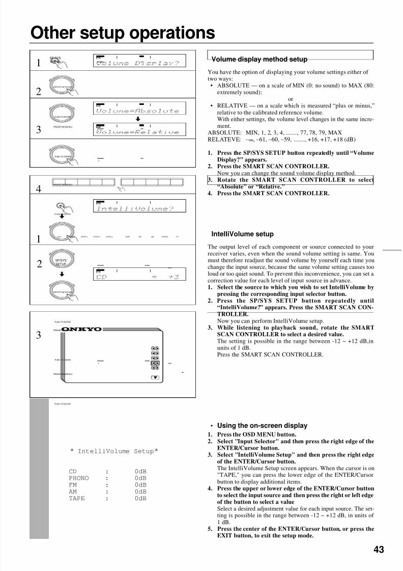
8/7/2019 Onkyo TX-DS676
http://slidepdf.com/reader/full/onkyo-tx-ds676 43/64
43
Other setup operations
• Using the on-screen display
1. Press the OSD MENU button.2. Select "Input Selector" and then press the right edge of the
ENTER/Cursor button.3. Select "IntelliVolume Setup" and then press the right edge
of the ENTER/Cursor button.The IntelliVolume Setup screen appears. When the cursor is on"TAPE," you can press the lower edge of the ENTER/Cursorbutton to display additional items.
4. Press the upper or lower edge of the ENTER/Cursor buttonto select the input source and then press the right or left edge
of the button to select a valueSelect a desired adjustment value for each input source. The set-ting is possible in the range between -12 ~ +12 dB, in units of 1 dB.
5. Press the center of the ENTER/Cursor button, or press theEXIT button, to exit the setup mode.
1
2
SP/SYS
SETUP
PRESET/MODE ADJ
PUSH TO ENTER
IntelliVolume setup
The output level of each component or source connected to yourreceiver varies, even when the sound volume setting is same. Youmust therefore readjust the sound volume by yourself each time youchange the input source, because the same volume setting causes tooloud or too quiet sound. To prevent this inconvenience, you can set acorrection value for each level of input source in advance.1. Select the source to which you wish to set IntelliVolume by
pressing the corresponding input selector button.
2. Press the SP/SYS SETUP button repeatedly until“IntelliVolume?” appears. Press the SMART SCAN CON-TROLLER.Now you can perform IntelliVolume setup.
3. While listening to playback sound, rotate the SMARTSCAN CONTROLLER to select a desired value.The setting is possible in the range between -12 ~ +12 dB,inunits of 1 dB.Press the SMART SCAN CONTROLLER.
* IntelliVolume Setup*
CD : 0dBPHONO : 0dBFM : 0dBAM : 0dB
TAPE : 0dB
Volume display method setup
You have the option of displaying your volume settings either of two ways:• ABSOLUTE — on a scale of MIN (0: no sound) to MAX (80:
extremely sound);
or• RELATIVE — on a scale which is measured “plus or minus,”relative to the calibrated reference volume.With either settings, the volume level changes in the same incre-ment.
ABSOLUTE: MIN, 1, 2, 3, 4, ......., 77, 78, 79, MAXRELATEVE: –∞, –61, –60, –59, ......., +16, +17, +18 (dB)
1. Press the SP/SYS SETUP button repeatedly until “VolumeDisplay?” appears.
2. Press the SMART SCAN CONTROLLER.Now you can change the sound volume display method.
3. Rotate the SMART SCAN CONTROLLER to select“Absolute” or “Relative.”
4. Press the SMART SCAN CONTROLLER.
PRESET/MODE ADJ
PUSH TO ENTER
3
SP/SYS
SETUP
3
1
PRESET/MODE ADJ
PUSH TO ENTER
2
V IDEO-1 V IDEO-2 V IDEO-3 V IDEO-4DVD FM AM PHONO C DTAPE
PRESET/MODE ADJ
PUSH TO ENTER
PRESET/MODE ADJ
PUSH TO ENTER
4PRESET/MODE ADJ
PUSH TO ENTER
SPEAKERS
A
DSP
SPEAKERS
A
DSP
SPEAKERS
A
DSP
SPEAKERS
A
STEREO
AUTO
SPEAKERS
A
db
AUTO
STEREO

8/7/2019 Onkyo TX-DS676
http://slidepdf.com/reader/full/onkyo-tx-ds676 44/64
44
MASTER VOLUME
STANDBY/ON
PHONESVIDEO CAM INPUT/ 4VIDEO
V ID EO A UD IOL R(MONO)S VIDEO
STAND-BY
AV RECEIVER TX-DS777
POWER
OFFON
A SPEAKERS B
TI CH INPUTMUL
FM AM PHONO C DTAPEVIDEO-1DVD VIDEO-4VIDEO-3VIDEO-2
DOWN
U P
FM MUTE/
MODE
CHARACTER/
MEMORY
SP/SYS
SETUP
SMART SCAN
CONTROLLER
MODE
AUDIO
ADJUSTMENT
BASS/
TREBLE
DISPLAY DSP REC OUT
PRESET/MODE ADJ
PUSH TO ENTER
DOWN TUNING UP
THX/DTS
SURROUND MODE
LISTENING MODE
STEREODIRECT
DIGITAL/
ANALOG CH LEVEL
DIMMER
Recording a source
Recording a source while listening to music or amovie
1. Select the source you wish to play (recording source) bypressing the corresponding input selector button.
See step 1 of “Selecting an input source” (page 26).2. Press the REC OUT button.
The REC OUT indicator blinks for 8 seconds.While the REC OUT indicator is blinking, rotate the SMARTSCAN CONTROLLER until "SOURCE" appears.
Notes:
• The digital input signals assigned to the input source you selected usingthe input selector buttons will be output to the DIGITAL OUTPUT ter-minal. There are some restrictions on digital recording. When makingdigital recordings, consult the instruction manual that came with yourdigital recording equipment (such as MD recorder or DAT deck) toknow what restrictions are imposed.
• You cannot select the source connected to the MULTI CHANNEL IN-PUT connectors. Even if you press the MULTI CH INPUT button in
step 1 above, the signals will be output to the L and R output jacks of theinput source you selected most recently.
4. Start recording on the recorder connected to the TAPE,VIDEO-1, VIDEO-2 jacks. Then, start playing the sourcecomponent you selected in step 1.
Notes:
• If you change the input source during recording, you will record thesignals from the newly selected input source.
• You cannot record the surround effects.
V IDEO-1 V IDEO-2 V IDEO-3 V IDEO-4DVD FM AM PHONO C DTAPE
3
1
2
PRESET/MODE ADJ
PUSH TO ENTER
1
2 PRESET/MODE ADJ
PUSH TO ENTER
REC OUT
Recording from on audio /video source
1. Press the REC OUT buttonThe REC OUT indicator binks for 8 seconds
2. While the REC OUT indicator is blinking, rotate theSMART SCAN CONTROLLER to select the desired re-cording source.
Notes:
• Selecting "SOURCE" sets the currently selected input source as the re-cording source.
• The digital input signals assigned to the input source you selected usingthe input selector buttons will be output to the DIGITAL OUTPUT ter-minal. There are some restrictions on digital recording. When makingdigital recordings, consult the instruction manual that came with yourdigital recording equipment (such as MD recorder or DAT deck) toknow what restrictions are imposed.
• You cannot select the source connected to the MULTI CHANNEL IN-PUT connectors. Even if you press the MULTI CH INPUT button instep 1 above, the signals will be output to the L and R output jacks of the
input source you selected most recently.3. Start recording on the recorder connected to the TAPE,
VIDEO-1, VIDEO-2 jacks. Then, start playing the sourcecomponent you selected in step 1.
Notes:
• If you change the input source during recording, you will record thesignals from the newly selected input source.
• You cannot record the surround effects.
Input selector buttons REC OUT
SMART SCAN CONTROLLER
REC OUT
SPEAKERS REC OUT
A
STEREO
REC OUT
REC OUT

8/7/2019 Onkyo TX-DS676
http://slidepdf.com/reader/full/onkyo-tx-ds676 45/64
45
Adding sound to a video tape
You can add CD or MD sound to your video recordings.The following is an example of adding sound to a video recordingusing the video cassette recorder connected to the VIDEO-1 jacks of the receiver. Let's assume that you will record the images from a
video camera connected to the VIDEO-4 VIDEO jack and the soundfrom a CD player.1. Press the CD input selector button.2. Press the SP/SYS SETUP button repeatedly until “Video
Assign?” appears and then press the SMART SCAN CON-TROLLER.
3. Rotate the SMART SCAN CONTROLLER until "VIDEO4" appears. Press the SMART SCAN CONTROLLER .
4. Insert a CD in the CD player. Or, insert a tape in the videocamera connected to the VIDEO-4 (VIDEO) jack.
5. Insert a tape to which recording is made in the video cassetterecorder connected to the VIDEO-1 (R, L, V) jacks.
6. Press the REC OUT button.The REC OUT indicator blinks for 8 seconds.
7. Rotate the SMART SCAN CONTROLLER to select
“SOURCE.”“CD” has been selected as the audio input source and “VIDEO4,” which you set in steps 1 to 3, as the video input source.
8. Start recording on the video cassette recorder connected tothe VIDEO-1 jacks. Then, start playing the CD player andthe video camera connected to the VIDEO-4 jack.
Notes:
• If you change the input source during recording, you will record theaudio signals from the newly selected input source and the video signalsassigned to that input source.
• You cannot record the surround effects.
Recording a source
3
SP/SYS
SETUP
4
1
2
• Using the on-screen display
You can use the on-screen display to set the recording equipment towhich the signals are output. By doing so, you can record signalsfrom the selected input source.1. Press the OSD MENU button.2. Select “Rec Selector” and press the right edge of the EN-
TER/Cursor button.The Rec Selector screen appears.The recording sources are shown on the left and the correspond-ing output jacks are shown on the right.
3. Press the right or left edge of the ENTER/Cursor button toselect the output jack.When Sound is set to “TAPE,” “TUNER,” “PHONE,” or “CD,”Picture shows the video source you set in “Assigning a video
source to each audio input source” (see page 40).To record the currently playing sound or video images, select“(SOURCE)” below the source name for Sound or Picture.
4. Press the center of the ENTER/Cursor button, or press theEXIT button, to exit the setup mode.
PRESET/MODE ADJ
PUSH TO ENTER
** Rec Selector **
•Picture VIDEO=DVD 1,2
•Sound TAPE=DVD VIDEO
1,2•Digital OPTICAL=---- OUT
ONO C D
PRESET/MODE ADJ
PUSH TO ENTER
PRESET/MODE ADJ
PUSH TO ENTER
5
6
7
8
REC OUT
PRESET/MODE ADJ
PUSH TO ENTER
SPEAKERS
A
DSP
SPEAKERS
A
DSP
SPEAKERS REC OUT
A
STEREO
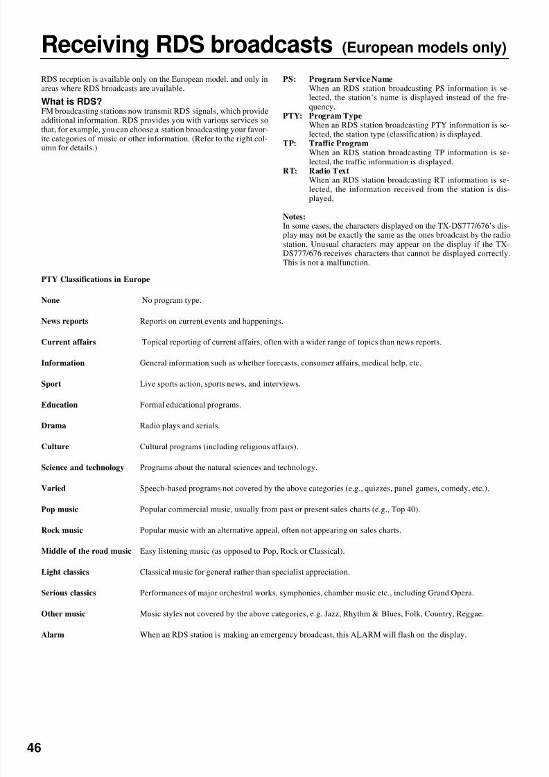
8/7/2019 Onkyo TX-DS676
http://slidepdf.com/reader/full/onkyo-tx-ds676 46/64
46
Receiving RDS broadcasts (European models only)
RDS reception is available only on the European model, and only inareas where RDS broadcasts are available.
What is RDS?FM broadcasting stations now transmit RDS signals, which provideadditional information. RDS provides you with various services sothat, for example, you can choose a station broadcasting your favor-ite categories of music or other information. (Refer to the right col-umn for details.)
PS: Program Service NameWhen an RDS station broadcasting PS information is se-lected, the station’s name is displayed instead of the fre-quency.
PTY: Program TypeWhen an RDS station broadcasting PTY information is se-
lected, the station type (classification) is displayed.TP: Traffic ProgramWhen an RDS station broadcasting TP information is se-lected, the traffic information is displayed.
RT: Radio TextWhen an RDS station broadcasting RT information is se-lected, the information received from the station is dis-played.
Notes:In some cases, the characters displayed on the TX-DS777/676’s dis-play may not be exactly the same as the ones broadcast by the radiostation. Unusual characters may appear on the display if the TX-DS777/676 receives characters that cannot be displayed correctly.This is not a malfunction.
PTY Classifications in Europe
None No program type.
News reports Reports on current events and happenings.
Current affairs Topical reporting of current affairs, often with a wider range of topics than news reports.
Information General information such as whether forecasts, consumer affairs, medical help, etc.
Sport Live sports action, sports news, and interviews.
Education Formal educational programs.
Drama Radio plays and serials.
Culture Cultural programs (including religious affairs).
Science and technology Programs about the natural sciences and technology.
Varied Speech-based programs not covered by the above categories (e.g., quizzes, panel games, comedy, etc.).
Pop music Popular commercial music, usually from past or present sales charts (e.g., Top 40).
Rock music Popular music with an alternative appeal, often not appearing on sales charts.
Middle of the road music Easy listening music (as opposed to Pop, Rock or Classical).
Light classics Classical music for general rather than specialist appreciation.
Serious classics Performances of major orchestral works, symphonies, chamber music etc., including Grand Opera.
Other music Music styles not covered by the above categories, e.g. Jazz, Rhythm & Blues, Folk, Country, Reggae.
Alarm When an RDS station is making an emergency broadcast, this ALARM will flash on the display.
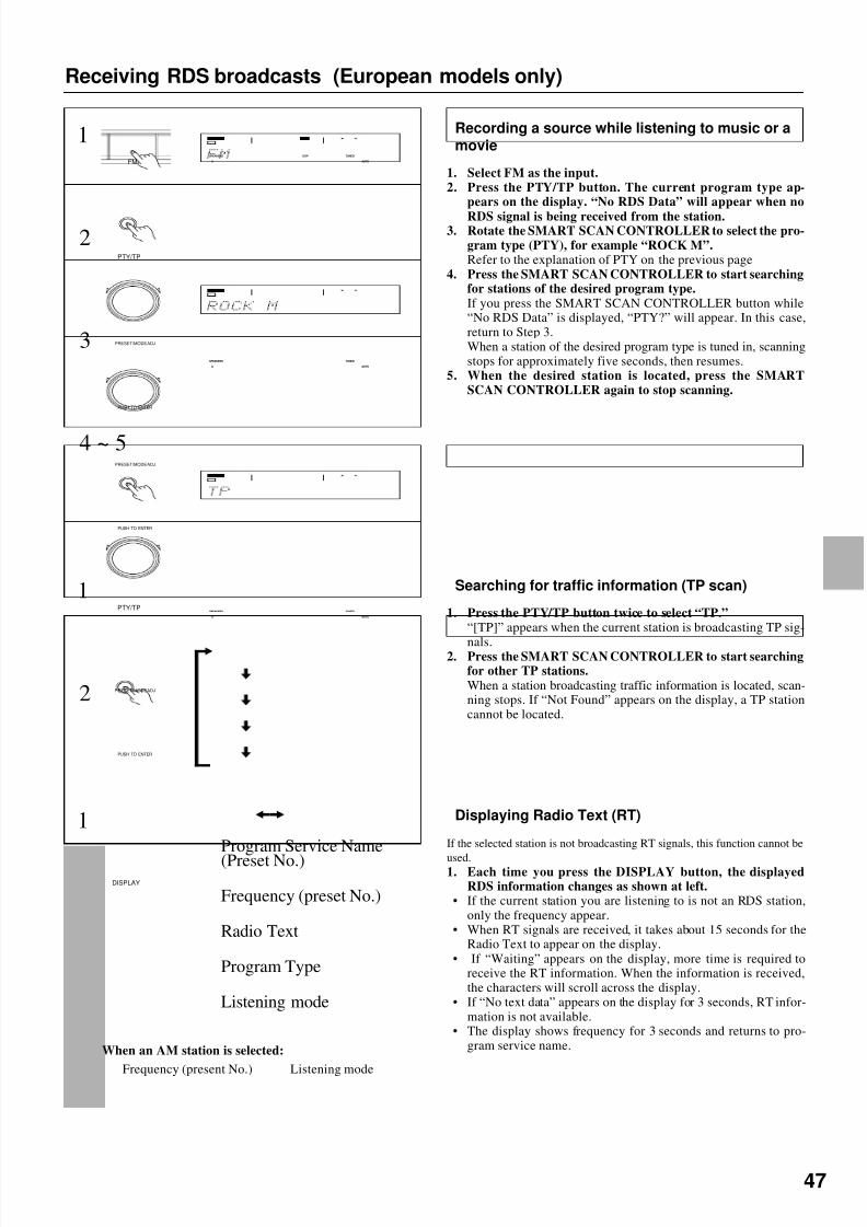
8/7/2019 Onkyo TX-DS676
http://slidepdf.com/reader/full/onkyo-tx-ds676 47/64
47
Receiving RDS broadcasts (European models only)
Recording a source while listening to music or amovie
1. Select FM as the input.2. Press the PTY/TP button. The current program type ap-
pears on the display. “No RDS Data” will appear when no
RDS signal is being received from the station.3. Rotate the SMART SCAN CONTROLLER to select the pro-
gram type (PTY), for example “ROCK M”.Refer to the explanation of PTY on the previous page
4. Press the SMART SCAN CONTROLLER to start searchingfor stations of the desired program type.If you press the SMART SCAN CONTROLLER button while“No RDS Data” is displayed, “PTY?” will appear. In this case,return to Step 3.When a station of the desired program type is tuned in, scanningstops for approximately five seconds, then resumes.
5. When the desired station is located, press the SMARTSCAN CONTROLLER again to stop scanning.
3
PTY/TP
1
2
1
2 PRESET/MODE ADJ
PUSH TO ENTER
PTY/TP
Displaying Radio Text (RT)
If the selected station is not broadcasting RT signals, this function cannot be
used.1. Each time you press the DISPLAY button, the displayedRDS information changes as shown at left.
• If the current station you are listening to is not an RDS station,only the frequency appear.
• When RT signals are received, it takes about 15 seconds for theRadio Text to appear on the display.
• If “Waiting” appears on the display, more time is required toreceive the RT information. When the information is received,the characters will scroll across the display.
• If “No text data” appears on the display for 3 seconds, RT infor-mation is not available.
• The display shows frequency for 3 seconds and returns to pro-gram service name.
4 ~ 5
Searching for traffic information (TP scan)
1. Press the PTY/TP button twice to select “TP.”“[TP]” appears when the current station is broadcasting TP sig-
nals.2. Press the SMART SCAN CONTROLLER to start searchingfor other TP stations.When a station broadcasting traffic information is located, scan-ning stops. If “Not Found” appears on the display, a TP stationcannot be located.
FM
Program Service Name(Preset No.)
Frequency (preset No.)
Radio Text
Program Type
Listening mode
DISPLAY
When an AM station is selected:
Frequency (present No.) Listening mode
1
PRESET/MODE ADJ
PUSH TO ENTER
PRESET/MODE ADJ
PUSH TO ENTER
SPEAKERS
A
DSP
AUTO
TUNED
SPEAKERS
A
TUNED
AUTO
SPEAKERS
A
TUNED
AUTO
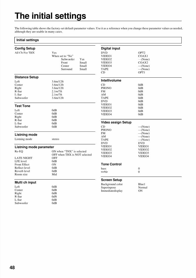
8/7/2019 Onkyo TX-DS676
http://slidepdf.com/reader/full/onkyo-tx-ds676 48/64
48
The initial settings
Config SetupAll Ch For THX Yes
When set to “No”Subwoofer YesFront SmallCenter SmallSurround Small
Distance Setup
Left 3.6m/12ftCenter 3.6m/12ftRight 3.6m/12ftR-Sur 2.1m/7ftL-Sur 2.1m/7ft
Subwoofer 3.6m/12ft
Test Tone
Left 0dBCenter 0dBRight 0dBR-Sur 0dBL-Sur 0dBSubwoofer 0dB
Listning mode
Listning mode stereo
Listning mode parameterRe-EQ ON when “THX” is selected
OFF when THX is NOT selectedLATE NIGHT OFFLFE level 0dBFront Effect ONReflect level 0dBReverb level 0dBRoom size Mid
Multi ch input
Left 0dBCenter 0dBRight 0dBR-Sur 0dBL-Sur 0dBSubwoofer 0dB
Digital inputDVD OPT2VIDEO1 COAX1VIDEO2 —(None)VIDEO3 COAX2VIDEO4 —(None)TAPE —(None)CD OPT1
Intellivolume
CD 0dBPHONO 0dBFM 0dBAM 0dB
TAPE 0dBDVD 0dBVIDEO1 0dBVIDEO2 0dBVIDEO3 0dBVIDEO4 0dB
Video assign Setup
CD —(None)PHONO —(None)FM —(None)AM —(None)TAPE —(None)DVD DVD
VIDEO1 VIDEO1VIDEO2 VIDEO2VIDEO3 VIDEO3VIDEO4 VIDEO4
Tone Control
bass 0treble 0
Screen Setup
Background color Blue1Superinpose NormalImmediatedisplay ON
The following table shows the factory-set default parameter values. Use it as a reference when you change these parameter values as needed,although they are usable in many cases.
Initial settings
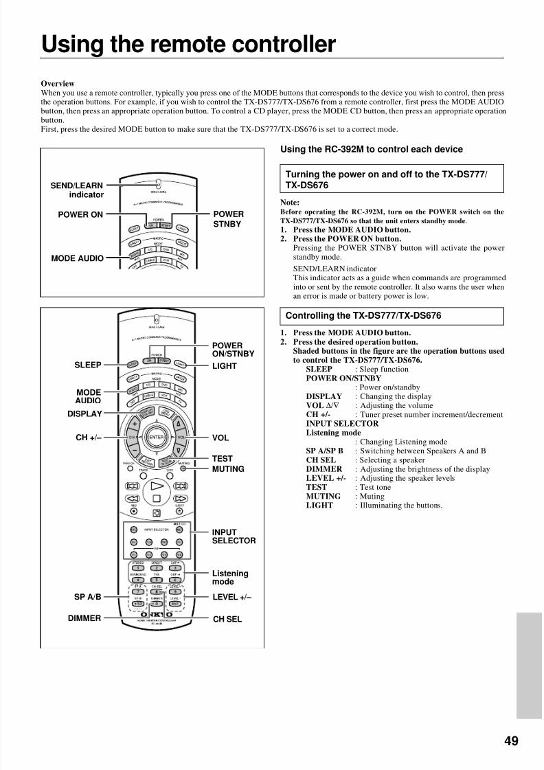
8/7/2019 Onkyo TX-DS676
http://slidepdf.com/reader/full/onkyo-tx-ds676 49/64

8/7/2019 Onkyo TX-DS676
http://slidepdf.com/reader/full/onkyo-tx-ds676 50/64
50
Using the remote controller
Controlling an Onkyo CD player
Note:
First connect an Onkyo CD player using the zconnection.(See page 7.)
1. Press the MODE CD button.2. Press the desired CD operation button.TRACK : Selecting a trackDISC : Selecting a disk in the CD changer
: Down
: Up
: Playback
: Stop
: Rewind
: Fast forward
: Pause
EJECT r : Eject0, 1~9, +10 : Numeric keys
You may also use the following buttons:VOL ∆/∇ : Adjusting the volume level of the
TX-DS777/TX-DS676MUTING : Muting the sound from the TX-DS777/
TX-DS676
Controlling an Onkyo DVD player
Note:Make sure that you point the transmission part on the remote con-troller toward the sensor area on the DVD player.1. Press the MODE DVD button.2. Press the desired DVD operation button.
POWER ON/STNBY: Turning the power on and off to the DVD
playerDVD SET : DVD setup
DVD player on-screen buttonMENU : Displaying the menu
: Moving the cursor
ENTER : Confirming the selectionRETURN : Return
DVD player buttons
: Down: Up
: Playback
: Stop
: Rewind
: Fast forward
: Pause
EJECT r : Eject0, 1~9, +10 : Numeric keysENT : Confirm
You may also use the following buttons:VOL ∆/∇ : Adjusting the volume level of the
TX-DS777/TX-DS676MUTING : Muting the sound from the TX-DS777/
TX-DS676Note:
The ENT button on the right below the numeric keys has the samefunction as “ENTER” of the ENTER/cursor button.
MODE CD
CDoperationbuttons
Numeric keys
MODE DVD
DVD SET
MENU
POWERON/STNBY
DVDoperationbuttons
Numeric keys,ENT button
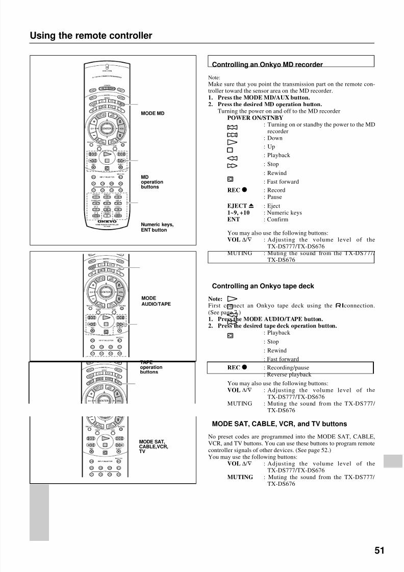
8/7/2019 Onkyo TX-DS676
http://slidepdf.com/reader/full/onkyo-tx-ds676 51/64
51
Using the remote controller
Controlling an Onkyo MD recorder
Note:Make sure that you point the transmission part on the remote con-troller toward the sensor area on the MD recorder.
1. Press the MODE MD/AUX button.2. Press the desired MD operation button.Turning the power on and off to the MD recorder
POWER ON/STNBY: Turning on or standby the power to the MD
recorder: Down
: Up
: Playback
: Stop
: Rewind
: Fast forward
REC o : Record: Pause
EJECT r : Eject1~9, +10 : Numeric keysENT : Confirm
You may also use the following buttons:VOL ∆/∇ : Adjusting the volume level of the
TX-DS777/TX-DS676MUTING : Muting the sound from the TX-DS777/
TX-DS676
Controlling an Onkyo tape deck
Note:First connect an Onkyo tape deck using the zconnection.(See page 7.)1. Press the MODE AUDIO/TAPE button.2. Press the desired tape deck operation button.
: Playback
: Stop
: Rewind
: Fast forward
REC o : Recording/pause: Reverse playback
You may also use the following buttons:VOL ∆/∇ : Adjusting the volume level of the
TX-DS777/TX-DS676MUTING : Muting the sound from the TX-DS777/
TX-DS676
MODE MD
MDoperationbuttons
Numeric keys,ENT button
MODEAUDIO/TAPE
TAPEoperationbuttons
MODE SAT,CABLE,VCR,TV
MODE SAT, CABLE, VCR, and TV buttons
No preset codes are programmed into the MODE SAT, CABLE,VCR, and TV buttons. You can use these buttons to program remotecontroller signals of other devices. (See page 52.)You may use the following buttons:
VOL ∆/∇ : Adjusting the volume level of theTX-DS777/TX-DS676
MUTING : Muting the sound from the TX-DS777/ TX-DS676

8/7/2019 Onkyo TX-DS676
http://slidepdf.com/reader/full/onkyo-tx-ds676 52/64
52
Programming the remote controller codesof other devices into the RC-392M
The RC-392M has two learning functions. One is a normal learning function that enables the RC-392M to learn other remote controllers’codes. The other is a macro learning function, which enables the RC-392M to learn a series of codes already memorized in the remotecontroller into one MACRO button.
Programming procedure
POW
ER
SLEEP
DIM
MER
SUR
MODE
VID
EO-1
VID
EO-2
TAP
E
DVD
C D
C D
DVD
TUNER
TUNER
PHONO
INPUT
SEL
ECTO
R
DIS
C
TAPE
VOLU
ME
LEVEL
CH S
EL
PRESET
MUTING
TEST
TONE
MULT
I-CH
INPU
T
REMOTE
CONTR
OLL
ER
GROUP
RC-385
S
4
3
2
1
Light
5 to 15 cm(2 to 6 inches)
RC-392M
Any button is programmable except for the eight Mode buttons(AUDIO, CD, DVD, MD, SAT, CABLE, VCR, and TV), twoMacro buttons (DIRECT and MODE), and LIGHT button.
1. Place the RC-392M and the remote controller for anotherdevice, with 5–15cm (2–6 inches) apart and the light-emit-ting parts facing each other.
2. While pressing and holding down the desired MODE buttonon the RC-392M (AUDIO, CD, DVD, MD, SAT, CABLE,VCR, or TV), press the ENT button, then release the but-tons.When you press and hold down one of the MODE button, theSEND/LEARN indicator lights up. When you press the ENTbutton, the indicator turns off. When you release the buttons, theSEND/LEARN indicator lights up again.
3. Press and release the desired operation button on the RC-392M.You may select any button within the rectangle shown in the
figure. When you press the button, the SEND/LEARN indicatorturns off. When you release the button, the indicator lights upagain.
4. Press and hold down the desired button on the remote con-troller of the other device until the SEND/LEARN indicatoron the RC-392M flashes twice.The SEND/LEARN indicator flashes twice slowly, then lightsup.
5. Repeat Steps 3–4 to program other buttons in the sameMODE.Repeat Steps 2-4 to program other buttons in a different MODE.
6. Press the MODE button to complete programming.7. Operate the programmed button to make sure the learning
function works.Note:
The remote controller codes for the Onkyo CD player, tapedeck, DVD player, and MD recorder have already been pro-grammed into the buttons on the RC-392M. You may programother remote controller codes into these buttons. If you wish torestore the Onkyo preset codes after you program new codes,erase the new codes. (See page 53.)
Note:
• The remote controller has 408 memory slots (51 buttons 8 modes), al-though this number varies significantly depending on the manufacturersand types of the remote controller you wish to program into the RC-392M. It is recommended that you determine which button functionshave priority for programming.
• If you do not press any button for more than 30 seconds during the pro-cedure, the SEND/LEARN indicator flashes three times quickly, thenthe RC-392M exits Learning mode. Resume Step 2.
• If you make a mistake during programming, the SEND/LEARN indica-tor flashes three times quickly, then the RC-392M exits Learning mode.
• If you try to program beyond the learning capacity of the RC-392M, theSEND/LEARN indicator flashes six times quickly, then the RC-392Mexits Learning function. Try programming in a button of other MODE.
• Follow the same procedure when you wish to program new codes intothe already-programmed buttons.• This remote controller uses infrared rays. Most remote controller codes
can be memorized using the infrared system; however, depending onthe degree to which the system differs, there may be some rare occa-sions when memorization is not possible.
• Some remote controllers use a single button to perform different func-tions, with the function code changing each time the button is pressed. If you are using this kind of controller, please perform the “learn” opera-tions for each function individually to store each function to a button onthe RC-392M.
• For instructions regarding the operation of “learned” units, please referto the instruction manual for each product.
• Even after codes have been memorized, please keep your old remotecontroller in a safe place. If the memorized codes are lost when the bat-
teries run down, it will be necessary to memorize them once again usingthe old remote controller.• Make sure both the RC-392M and the product’s own remote controller
have fresh batteries. If either of them has batteries that are wearingdown, it may be impossible to store the remote controller codes into theRC-392M or the product may not respond properly to the buttons on theRC-392M for which the remote controller codes were stored intomemory.
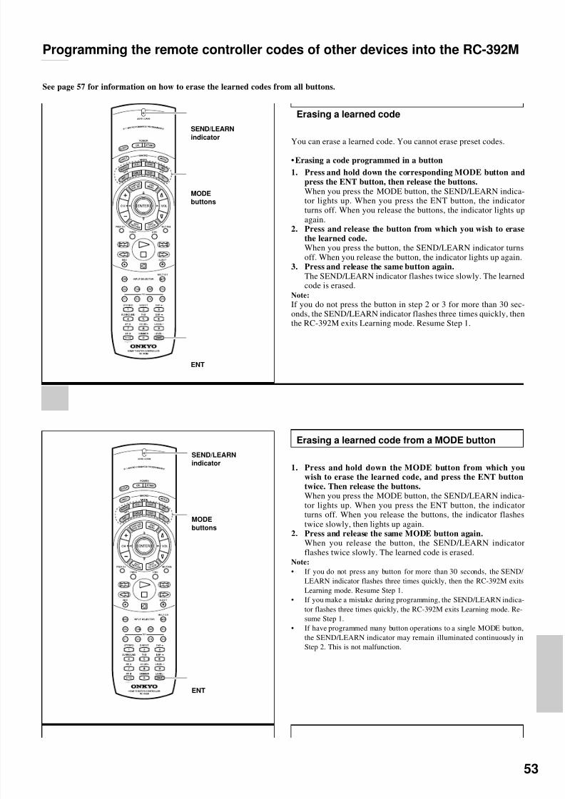
8/7/2019 Onkyo TX-DS676
http://slidepdf.com/reader/full/onkyo-tx-ds676 53/64
53
Programming the remote controller codes of other devices into the RC-392M
See page 57 for information on how to erase the learned codes from all buttons.
Erasing a learned code
You can erase a learned code. You cannot erase preset codes.
•Erasing a code programmed in a button
1. Press and hold down the corresponding MODE button andpress the ENT button, then release the buttons.When you press the MODE button, the SEND/LEARN indica-tor lights up. When you press the ENT button, the indicatorturns off. When you release the buttons, the indicator lights upagain.
2. Press and release the button from which you wish to erasethe learned code.When you press the button, the SEND/LEARN indicator turnsoff. When you release the button, the indicator lights up again.
3. Press and release the same button again.
The SEND/LEARN indicator flashes twice slowly. The learnedcode is erased.Note:
If you do not press the button in step 2 or 3 for more than 30 sec-onds, the SEND/LEARN indicator flashes three times quickly, thenthe RC-392M exits Learning mode. Resume Step 1.
Erasing a learned code from a MODE button
1. Press and hold down the MODE button from which youwish to erase the learned code, and press the ENT buttontwice. Then release the buttons.When you press the MODE button, the SEND/LEARN indica-tor lights up. When you press the ENT button, the indicatorturns off. When you release the buttons, the indicator flashestwice slowly, then lights up again.
2. Press and release the same MODE button again.When you release the button, the SEND/LEARN indicatorflashes twice slowly. The learned code is erased.
Note:
• If you do not press any button for more than 30 seconds, the SEND/ LEARN indicator flashes three times quickly, then the RC-392M exitsLearning mode. Resume Step 1.
• If you make a mistake during programming, the SEND/LEARN indica-tor flashes three times quickly, the RC-392M exits Learning mode. Re-sume Step 1.
• If have programmed many button operations to a single MODE button,the SEND/LEARN indicator may remain illuminated continuously inStep 2. This is not malfunction.
SEND/LEARN
indicator
MODEbuttons
ENT
SEND/LEARNindicator
MODE
buttons
ENT

8/7/2019 Onkyo TX-DS676
http://slidepdf.com/reader/full/onkyo-tx-ds676 54/64
54
Using a Macro function
What is a Macro function?
A Macro function enables you to program a series of button operations on the remote controller into a single button. For example, you needto follow the steps below to play a CD player connected to the TX-DS777/TX-DS676 without using the Macro function:1: Press the MODE AUDIO button. → 2: Press the POWER ON button. → 3: Press the CD (INPUT SELECTOR) button.→ 4: Press the
MODE CD button. → 5: Use the numeric keys to select the desired song.This operation will be two button presses away if you program these steps into a macro button.
Programming Macro mode
You may program the desired steps into each of eight MODE but-tons. The following example explains how to program Steps 1–5(described above) into the MACRO MODE button under theMODE CD button (CD mode).1. Press and hold down the desired MODE button you wish to
program (in this case, MODE CD button), and press theMACRO MODE button. Then release the buttons.When you press the MODE CD button, the SEND/LEARN indi-cator lights up. When you press the MACRO MODE button, the
indicator turns off.When you release the buttons, the indicator flashes briefly, thenlights up again.
2. Press the operation buttons in series you wish to programinto the MACRO MODE button.Press the MODE AUDIO, POWER ON, CD (INPUT SELEC-TOR), MODE CD buttons, and a numeric key. When you pressthe button, the SEND/LEARN indicator turns off. When you re-lease the button, the indicator lights up.
3. Press the MACRO MODE button to complete program-ming.The SEND/LEARN indicator flashes twice slowly.Repeat Steps 1–3 to program other series of button operationsinto another MODE button.
4. Check to see if the series of button operation has been cor-
rectly learned.Point the remote controller toward the TX-DS777/676, press theMODE CD button, and press the MACRO MODE button to seeif the unit responds as programmed.Transmitting the codes in Macro mode takes a while. Duringtransmission, point the remote controller toward the device to becontrolled.
Note:
• You may program up to 16 button operations into each MACRO button.If you try to program the 17th step, it will be ignored.
• If you do not press any button for more than 30 seconds during the pro-cedure, the SEND/LEARN indicator flashes three times quickly, thenthe RC-392M exits Learning mode. Resume Step 1.
• If you make a mistake during programming, the SEND/LEARN indica-tor flashes three times quickly, then the RC-392M exits Learning mode.Resume Step 1.
• If you erase one of the operation buttons already programmed in theMACRO MODE button, or if you program a different code into such abutton, the operation button will no longer work. In this case, programthe buttons again to avoid malfunction.
Tip:
The codes programmed into a MACRO buttonwill be transmitted with an interval of 0.5 sec-onds. However, some devices may not be ableto complete one operation in 0.5 seconds andmay miss the next code. In this case, press oneoperation button, press the correspondingMODE button, then press another operationbutton to extend the interval between the twooperations up to one second.
1, 3
2
1, 22
2
2

8/7/2019 Onkyo TX-DS676
http://slidepdf.com/reader/full/onkyo-tx-ds676 55/64
55
Using a Macro function
Macro Direct Learning function
A series of remote controller button operations can be memorizedinto the MACRO DIRECT button for one-touch control.
Note:You can program only one series of button operations into theMACRO DIRECT button.1. Press and hold down any one of the eight MODE buttons
and press the MACRO DIRECT button. Then, release thebuttons.When you press the MODE button, the SEND/LEARN indica-tor lights up. When you press the MACRO DIRECT button, theindicator turns off. When you release the buttons, the indicatorflashes briefly, then lights up again.
2. Follow Steps 2 in the “Programming Macro Mode” on page54.
3. Press the MACRO DIRECT button to complete the proce-dure.The SEND/LEARN indicator flashes twice slowly.
4. Check to see if the button has been programmed correctly.Point the RC-392M toward the TX-DS777/TX-DS676 and pressthe MACRO DIRECT button, and make sure that the device re-sponds as programmed.Transmitting the codes in Macro mode takes a while. Duringtransmission, point the remote controller toward the device to becontrolled.
Note:
• You may program up to 16 button operations into the MACRO DI-RECT button. If you try to program the 17th step, it will be ignored.
• If you do not press any button for more than 30 seconds during the pro-cedure, the SEND/LEARN indicator flashes three times quickly, thenthe RC-392M exits Learning mode. Resume Step 1.
• If you make a mistake during programming, the SEND/LEARN indica-
tor flashes three times quickly, then the RC-392M exits Learning mode.Resume Step 1.• If you erase one of the operation buttons already programmed in the
MACRO DIRECT button, or if you program a different code into such abutton, the operation button will no longer work. In this case, programthe buttons again to avoid malfunction.
Tip:The codes programmed into a MACRObutton will be transmitted with an intervalof 0.5 seconds. However, some devicesmay not be able to complete one operationin 0.5 seconds and may miss the nextcode. In this case, press one operationbutton, press the corresponding MODEbutton, then press another operation but-ton to extend the interval between the twooperations up to one second.
1, 3
1

8/7/2019 Onkyo TX-DS676
http://slidepdf.com/reader/full/onkyo-tx-ds676 56/64
56
Erasing a learned remote controller buttonoperation from the MACRO MODE buttons
1. Press and hold down the corresponding MODE button andpress the MACRO MODE button, then release the buttons.
When you press the MODE button, the SEND/LEARN indica-tor lights up. When you press the MACRO MODE button, theindicator turns off. When you release the buttons, the indicatorflashes once.
2. Press the MACRO MODE button again.The SEND/LEARN indicator flashes twice slowly. The learnedoperation is erased.
Using a Macro function
Erasing a learned remote controller buttonoperation from the MACRO DIRECT button
1. Press and hold down any one of the MODE buttons andpress the MACRO DIRECT button. Then release the but-tons.When you press the MODE button, the SEND/LEARN indica-tor lights up. When you press the MACRO DIRECT button, theindicator turns off. When you release the buttons, the indicatorflashes once.
2. Press the MACRO DIRECT button again.The SEND/LEARN indicator flashes twice slowly. The learnedoperation is erased.
Note:
• If you do not press any button for more than 30 seconds, the SEND/ LEARN indicator flashes three times quickly, then the RC-392M exitsLearning mode. Resume Step 1.
• If you press a wrong button in Step 2, you may have overwritten thememory of the button you pressed.
1, 2
1
1
1, 2

8/7/2019 Onkyo TX-DS676
http://slidepdf.com/reader/full/onkyo-tx-ds676 57/64
57
Erasing all codes and operations programmed inthe buttons
This procedure will erase all remote controller codes for the otherdevices and all macro operations that have been programmed in the
RC-392M (see pages 52, 54 and 55).1. Open the battery cover and remove the batteries.2. While pressing and holding down the POWER ON button
and the POWER STNBY button, insert the batteries in thecorrect direction.After inserting the batteries, release the buttons. The SEND/ LEARN indicator flashes slowly.
3. Press the ENT button.The SEND/LEARN indicator lights up for about ten seconds,then turns off.All programmed codes are erased and the button memories re-turn to the factory presets.
Note:
• Proceed to Step 3 immediately after Step 2. Otherwise, the batteries willbe consumed quickly.
• If you press any button other than the ENT button in Step 3, no codeswill be erased. In this case, repeat the steps from the beginning.
2
3
Using a Macro function

8/7/2019 Onkyo TX-DS676
http://slidepdf.com/reader/full/onkyo-tx-ds676 58/64
58
Troubleshooting guideIf a problem occurs while you are using the remote controller, first try to operate the front panel controls on the main unit to make sure thatit is not due to a malfunction (or worn out batteries) in the remote controller.
Trouble
POWERPower shut off immedi-
ately after power on.
No power.
Power on but no sound.
The sound of the play-
back source is not heard.
No picture appears on
the TV screen (or moni-
tor)
SPEAKERS
No sound from the cen-
ter speaker, or very
minimal sound.
No sound or quiet sound
from subwoofer
PHONO
Hum, low-frequency
noise.
Howling when the vol-
ume is turned up.
Rough or scratchy
sound. High range is notclear.
FM/AM
AM stations cannot be
received.
Buzzing noise on AM
(particularly conspicu-
ous at night or with
weak stations).
High-pitched noise or
buzzing noise on AM.
Crackling noise on AM,
FM.
Cause
• Amplifier protection circuitry has been acti-
vated.
• Power cord is disconnected.
• There is external noise in the computer circuits
of this unit.
• AC fuse blown.
• “Muting” is displayed.
• The digital/analog input setting is incorrect.
• Bad connections.
• Amplifier protection circuitry has been acti-
vated.
• The input selector is not set properly.
• The TV (or monitor) is not set to receive the out-
put signals from the reciver.
• The video cable is not connected securely.
• Only S video connection is made.
• Speaker cable is not corrected.
• Listening mode is set to Stereo or Direct.
• CENTER level is set to minimum.
• CENTER SPEAKER is set to None.• Subwoofer is set to No.
• Subwoofer speakers output level setting is im-
proper.
• Poor or no input ground.
• Poor or no phono motor ground.
• The placement of the audio connection cables
on the rear panel is incorrect.
• Turntable and speakers are too close together.
• Stylus of turntable pick-up is worn.
• Turntable stylus tip is dirty.• Treble control too high.
• AM loop antenna is not attached.
• Noise from electrical apparatus such as fluores-
cent lamp.
• Noise from TV set.
• Noise caused by turning fluorescent lamp on
and off.
• Noise from automobile ignition.
Remedy
• Remove the AC plug from the outlet immediately.
Then contact your Onkyo service center.
• Connect power cord.
• Turn the power button off and then on again or remove
the AC plug from the outlet and then plug it again.
• Contact your Onkyo Service Center.
• Press the MUTING button on the remote controller to
turn it off.
• Select the correct input.
• Check connections, speaker leads, etc.
• Contact your Onkyo Service Center.
• Set it to the playback source.
• Set the TV (or monitor) to the receiver input.
• Check the connections.
• Make also video connection.
• Check the connection between the amplifier and the
speaker.
• Set the Listening mode to any mode other than Stereo
or Direct.
• Set the CENTER level to the appropriate volume.
• Set CENTER SPEAKER to Large or Small.• Check the speaker setting.
• Check the output level of the Subwoofer using the test
tone.
• Check outer conductor of input plugs.
• Check for proper ground connection.
• Adjust the placement of the cable to reduce hum.
• Move them farther apart.
• Replace.
• Clean.• Turn treble control down.
• Connect the included AM loop antenna to the AM an-
tenna terminals.
• Move the AM loop antenna to different position.
• Set up an outdoor AM antenna.
• Place the AM loop antenna as far as possible from the
TV.
• Move unit away from TV set.
• Move antenna as far as possible from the fluorescent
lamp.
• Install an FM outdoor antenna as far as possible from
the road.
• Change the position or direction of the outdoor an-
tenna.
Seepage
-
13
13
-
31
23, 29
6~15
-
26, 27
8
8
8
11
34~38
21
18, 1912
22
6
6
-
-
-
-31
14
15
15
15
-
15
15
15

8/7/2019 Onkyo TX-DS676
http://slidepdf.com/reader/full/onkyo-tx-ds676 59/64
59
Also refer to the respective instruction manuals of the video disc player, video cassette recorder, TV monitor, etc., that compose yourentertainment system.
Because the unit contains a microcomputer to provide advanced functions, it may malfunction due to external noise or static electricity. If thishappens, press the POWER switch on the unit and then press it in again after about five seconds.
Troubleshooting guide
Trouble
FM/AM
TUNED and STEREO
indicators light butsound is distorted and
stereo separation is bad.
TUNED and STEREO
indicators flicker and
hiss is heard on FM.
No station is recalled.
Video & audio
Desired picture does
no t appear when
MULTI CH INPUT but-
ton is pressed.
No on-screen display.
Picture and sound do not
match.
No sound, or sound of
the selected source is
not heard.
No picture appears on
the TV screen (or moni-
tor).
Others
LATE NIGHT function
cannot be used.
LFE LEVEL function
cannot be used.
Cinema Re-EQ function
cannot be used.
Parameter cannot be set
for Front Effect, Reflect
Level, Reverb Level,
Room Size, etc.
Front panel controls
function but remotecontroller does not.
Cause
• Station is too strong.
• Multiple reflection of the radio waves becauseof tall buildings or mountains.
• Station is too weak.
• Stereo FM broadcasts cover only about half the
distance of an ordinary broadcast.
• The power cord has been unplugged or the
POWER switch has been turned off for a long
time.
• Wrong connection.
• No video input is assigned.
• Improper connection.
• Improper OSD selector setting.
• Improper connection.
• Improper video is assigned.
• The digital input selector is not set properly.
• The TV (or monitor) is not set to receive the out-
put signals from the receiver.
• The video cable is not connected securely.
• Only S-Video connection is made.
• Playback source is not Dolby Digital encoded.
• Playback source is not Dolby Digital , DTS,
MPEG encoded.
• The listening mode is set to “Stereo,” “5ch ste-
reo” or “Direct.”
• Parameter may not be set depending on the lis-
tening mode.
• No batteries in remote controller.
• Batteries have worn out.• The remote controller is not pointed at the re-
mote sensor of the receiver.
• The remote controller is too far from the
reciever.
Remedy
• Change to FM indoor antenna.
• Use antenna which has better directivity and select apoint where the distortion is least.
• Install an outdoor FM antenna.
• Change the position or direction of the outdoor an-
tenna.
• The memory contents are lost. Store all stations again.
• Check the connection again. Insert the plugs and con-
nectors completely.
• Assign a proper video input.
• Check connections.
• Set the OSD selector properly.
• Check connections.
• Check Video Assign setting.
• Check Digital Input setting.
• Set the TV (or monitor) to the receiver input.
• Check connections.
• Make also video connection.
• Check that the DOLBY DIGITAL indicator lights up
on the display.
• Check that the DOLBY DIGITAL , DTS, MPEG in-
dicator lights up on the display.
• See the table on page 38.
• See the table on page 38.
• Insert batteries.
• Replace batteries.• Point the remote controller at the remote sensor of the
reciever.
• Operate the remote controller within 16 feet (5m).
Seepage
15
15
15
15
25
9
33
8
8, 9
8
40
23, 29
-
8
8
38
38
38
38
5
55
5

8/7/2019 Onkyo TX-DS676
http://slidepdf.com/reader/full/onkyo-tx-ds676 60/64
60
Specifications
TX-DS777
AMPLIFIER SECTION
Continuous Average Power output (FTC)All channels: 105 watts per channel min. RMS at 8
ohms, 2 channels driven from 20 Hz
to 20 kHz with no more than 0.08%
total harmonic distortion.
135 watts min. RMS at 6 ohms, 2
channels driven from 1 kHz with no
more than 0.1% total harmonic dis-
tortion.
Continuous Power output (DIN) 140 watts at 6 ohmsMaximum Power output (EIAJ) 170 watts at 6 ohmsTotal Harmonic Distortion: 0.08% at rated power (Front)IM Distortion: 0.08% at rated power (Front)Damping Factor: 60 at 8 ohms (Front)Input Sensitivity and Impedance
PHONO: 2.5 mV, 50 kohmsLINE (CD, TAPE, DVD,
VIDEO 1, 2, 3,4): 200 mV, 50 kohmsMULTICHANNEL INPUT(FRONT L/R, SURROUND L/R, CENTER):
200 mV, 50 kohms(SUBWOOFER): 36 mV, 50 kohmsCOAXIAL 1, 2 (DIGITAL): 0.5 Vp-p, 75 ohms
Output Level and ImpedanceRec out (TAPE, VIDEO 1): 200 mV, 2.2 kohmsPre out: 1 V, 470 ohms
Phono Overload: 110 mV RMS at 1 kHz, 0.5% T.H.D.Frequency Response: 20 Hz to 100 kHz, +1/-3 dB(LINE INPUT)
RIAA Deviation: 20 Hz to 20 kHz, ±0.8 dBTone Control
Bass: ±10 dB at 100 HzTreble: ±10 dB at 10 kHz
Signal-to-Noise RatioPhono: 80 dB (IHF A, 5 mV input)CD/Tape: 100 dB (IHF A)
VIDEO SECTION
Input sensitivity/Impedance(DVD, VIDEO 1, 2, 3,4)VIDEO (Composite): 1 Vp-p, 75 ohms
Output Level/Impedance(VIDEO 1, 2, MONITOR)VIDEO (Composite): 1 Vp-p, 75 ohms
TX-DS676
AMPLIFIER SECTION
Continuous Average Power output (FTC)All channels: 85 watts per channel min. RMS at 8
ohms, 2 channels driven from 20 Hz
to 20 kHz with no more than 0.08%
total harmonic distortion.
110 watts min. RMS at 6 ohms, 2
channels driven from 1 kHz with no
more than 0.1% total harmonic dis-
tortion.
Continuous Power output (DIN) 115 watts at 6 ohmsMaximum Power output (EIAJ) 145 watts at 6 ohmsTotal Harmonic Distortion: 0.08% at rated power (Front)IM Distortion: 0.08% at rated power (Front)Damping Factor: 60 at 8 ohms (Front)Input Sensitivity and Impedance
PHONO: 2.5 mV, 50 kohmsLINE (CD, TAPE, DVD,
VIDEO 1, 2, 3,4): 200 mV, 50 kohmsMULTICHANNEL INPUT(FRONT L/R, SURROUND L/R, CENTER):
200 mV, 50 kohms(SUBWOOFER): 36 mV, 50 kohmsCOAXIAL 1, 2 (DIGITAL): 0.5 Vp-p, 75 ohms
Output Level and ImpedanceRec out (TAPE, VIDEO 1): 200 mV, 2.2 kohmsPre out: 1 V, 470 ohms
Phono Overload: 110 mV RMS at 1 kHz, 0.5% T.H.D.Frequency Response: 20 Hz to 100 kHz, +1/-3 dB(LINE INPUT)
RIAA Deviation: 20 Hz to 20 kHz, ±0.8 dBTone Control
Bass: ±10 dB at 100 HzTreble: ±10 dB at 10 kHz
Signal-to-Noise RatioPhono: 80 dB (IHF A, 5 mV input)CD/Tape: 100 dB (IHF A)
VIDEO SECTION
Input sensitivity/Impedance(DVD, VIDEO 1, 2, 3,4)VIDEO (Composite): 1 Vp-p, 75 ohms
Output Level/Impedance(VIDEO 1, 2, MONITOR)VIDEO (Composite): 1 Vp-p, 75 ohms

8/7/2019 Onkyo TX-DS676
http://slidepdf.com/reader/full/onkyo-tx-ds676 61/64
61
Specifications
TX-DS777
TUNER SECTION
FMTuning Range: 87.5 — 108.0 MHz (50 kHz steps)Usable Sensitivity
Mono: 11.2 dBf, 1.0 µV (75 ohms IHF)0.9 µV (75 ohms DIN)
Stereo: 17.2 dBf, 2.0 µV (75 ohms IHF)23 µV (75 ohms DIN)
50 dB Quieting SensitivityMono: 17.2 dBf, 2.0 µV (75 ohms)Stereo: 37.2 dBf, 20 µV (75 ohms)
Capture Ratio: 2.0 dBImage Rejection Ratio
U.S.A. & Canadian models: 40 dBOther area models: 85 dB
IF Rejection Ratio: 90 dBSignal-to-Noise Ratio
Mono: 76 dBStereo: 70 dBAlternate Channel Attenuation: 55 dBSelectivity: 50 dB (DIN)AM Suppression Ratio: 50 dBTotal Harmonic Distortion
Mono: 0.2%Stereo: 0.3%
Frequency Response: 30 Hz — 15 kHz, ±1.0 dBStereo Separation: 45 dB at 1 kHz
30 dB at 100 Hz — 10 kHz
AM
Tuning RangeU.S.A. & Canadian models: 530—1,710 kHz (10 kHz steps)
European & Australian models: 522—1,611 kHz (9 kHz steps)Worldwide models: 531—1,602 kHz (9 kHz steps),530—1,710 kHz (10 kHz steps)
Usable Sensitivity: 30 µVImage Rejection Ratio: 40 dBIF Rejection Ratio: 40 dBSignal-to-Noise Ratio: 40 dBTotal Harmonic Distortion: 0.7%
GENERAL
Power Supply: AC 120 V, 60 HzAC 230 V, 50 HzAC 220-230 V and 120 V switchable,50/60 Hz
Power Consumption: 6.2 A
520 WDimensions (W × H × D): 435 × 175 × 453 mm17-1/8" × 6-7/8" × 17-13/16"
Weight:USA & Canadian models: 16.3 kg, 35.9 lbs.Others: 17.6 kg, 38.8 lbs.
REMOTE CONTROL
Transmitter: InfraredSignal range: Approx. 5 meters, 16 ft.Power supply: Two “AA” batteries (1.5 V × 2)
Specifications and features are subject to change without notice.
Power supply and voltage vary depending on the area in which the unit is
purchased.
TX-DS676
TUNER SECTION
FMTuning Range: 87.5 — 108.0 MHz (50 kHz steps)Usable Sensitivity
Mono: 11.2 dBf, 1.0 µV (75 ohms IHF)0.9 µV (75 ohms DIN)
Stereo: 17.2 dBf, 2.0 µV (75 ohms IHF)23 µV (75 ohms DIN)
50 dB Quieting SensitivityMono: 17.2 dBf, 2.0 µV (75 ohms)Stereo: 37.2 dBf, 20 µV (75 ohms)
Capture Ratio: 2.0 dBImage Rejection Ratio
U.S.A. & Canadian models: 40 dBOther area models: 85 dB
IF Rejection Ratio: 90 dBSignal-to-Noise Ratio
Mono: 76 dBStereo: 70 dBAlternate Channel Attenuation: 55 dBSelectivity: 50 dB (DIN)AM Suppression Ratio: 50 dBTotal Harmonic Distortion
Mono: 0.2%Stereo: 0.3%
Frequency Response: 30 Hz — 15 kHz, ±1.0 dBStereo Separation: 45 dB at 1 kHz
30 dB at 100 Hz — 10 kHz
AM
Tuning RangeU.S.A. & Canadian models: 530—1,710 kHz (10 kHz steps)
European & Australian models: 522—1,611 kHz (9 kHz steps)Worldwide models: 531—1,602 kHz (9 kHz steps),530—1,710 kHz (10 kHz steps)
Usable Sensitivity: 30 µVImage Rejection Ratio: 40 dBIF Rejection Ratio: 40 dBSignal-to-Noise Ratio: 40 dBTotal Harmonic Distortion: 0.7%
GENERAL
Power Supply: AC 120 V, 60 HzAC 230 V, 50 HzAC 220-230 V and 120 V switchable,50/60 Hz
Power Consumption: 5.3 A
410 WDimensions (W × H × D): 435 × 175 × 453 mm17-1/8" × 6-7/8" × 17-13/16"
Weight:USA & Canadian models: 14.7 kg, 32.4 lbs.Others: 15.5 kg, 34.2 lbs.
REMOTE CONTROL
Transmitter: InfraredSignal range: Approx. 5 meters, 16 ft.Power supply: Two “AA” batteries (1.5 V × 2)
Specifications and features are subject to change without notice.
Power supply and voltage vary depending on the area in which the unit is
purchased.

8/7/2019 Onkyo TX-DS676
http://slidepdf.com/reader/full/onkyo-tx-ds676 62/64
62
Front panel
For more information about buttons or knobs, refer to the pageslisted in the brackets ( [ ] ) below.1. STANDBY indicator [5, 13]2. STANDBY/ON button[13]3. POWER switch [13]4. SPEAKERS A/B button [26, 30]5. DISPLAY button [23, 30, 47]6. DIMMER button (Other than European model) [26]
PTY/TP button (European model) [47]7. Display (Refer to the “Display” illustration.)8. LISTENING MODE buttons [35, 36, 38]
The bottuns vary depending on the model you purchased.9. FM MUTE/MODE button [24]
10. TUNING UP/DOWN button [23]11. Remote control sensor [5]12. CHARACTER/MEMORY buttons [25, 41]13. SP/SYS SETUP button [16, 18, 20~22, 40, 43 ]14. AUDIO ADJUSTMENT button [38]15. BASS/TREBLE button [31]
16. SMART SCAN CONTROLLER [16, 32]17. MASTER VOLUME control knob [26, 35]18. VIDEO-4/VIDEO CAM INPUT [8]19. CH LEVEL button [42]20. DIGITAL/ANALOG button [23, 28]21. REC OUT button [44, 45]
Control positions and names
22. INPUT SELECTOR buttons [23, 26, 32, 35]23. MULTI CHANNEL INPUT button [33]24. PHONES [26]
Display
If a protective film on the surface of the screen making it difficult toread the display, remove the film.a. Speakers A/B indicatorsb. Rec out indicatorc. Sleep indicatord. PCM digital indicatore. Listening mode or Digital input format indicators
(The MPEG indicator appears on the European model (TX-DS777/ TX-DS676) and the worldwide model (TX-DS777) only.)
f. Memory indicatorg. RDS station received indicator (European model only)h. FM Stereo indicatori. Tuned indicatorsj. Auto indicatork. Multi function display
(Frequency and Preset station/Input selector/Sleep time/ Volume level/Listening mode)
MASTER VOLUME
STANDBY/ON
PHONESVIDEO CAM INPUT/ 4VIDEO
V ID EO A UD IOL R(MONO)S VIDEO
STAND BY
AV RECEIVER TX-DS777
POWER
OFFON
A SPEAKERS B
TI CH INPUTMUL
FM AM PHONO C DTAPEVIDEO-1DVD VIDEO-4VIDEO-3VIDEO-2
DOWN
U P
FM MUTE/
MODE
CHARACTER/
MEMORY
SP/SYS
SETUP
SMART SCAN
CONTROLLER
MODE
AUDIO
ADJUSTMENT
BASS/
TREBLE
DISPLAY DSP REC OUT
PRESET/MODE ADJ
PUSH TO ENTER
DOWN TUNING UP
THX/DTS
SURROUND MODE
LISTENING MODE
STEREODIRECTDIGITAL/
ANALOG CH LEVEL
DIMMER
SPEAKERS REC OUT
A B PCM DIGITAL DIRECT MEMORY FM STEREO AUTODOLBY PRO LOGIC
SLEEP DTS DSP RDSSTEREO TUNED
ft
ch
dB
MPEGDOLBY DIGITAL
1 2 3 4 5 6 7 8 9 10 11 12 13 14 15 16 17
18192021222324
a b c d e f g h i j
k
The illustration shows the front panel of the TX-DS777 model VS.The appearance of the front panel varies depending on the model youpurchased.
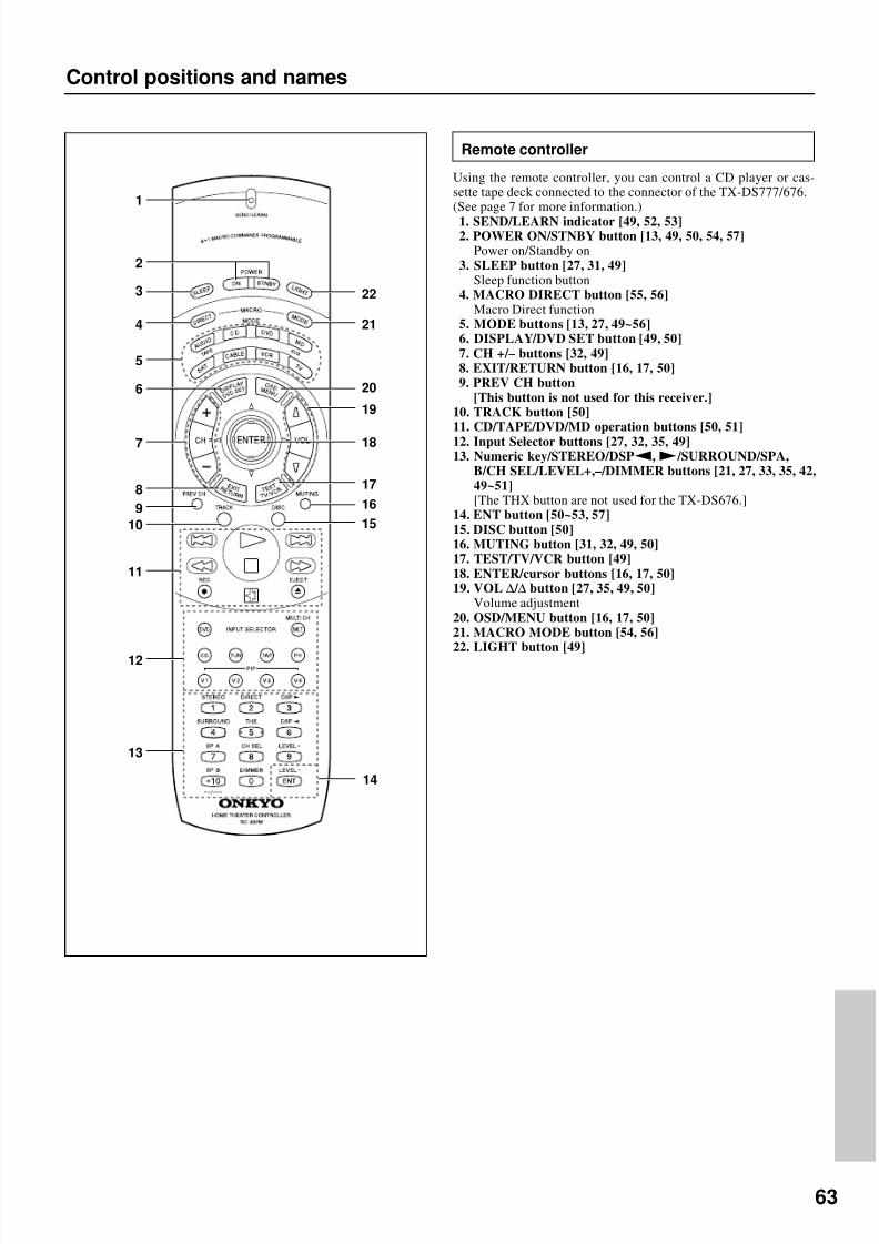
8/7/2019 Onkyo TX-DS676
http://slidepdf.com/reader/full/onkyo-tx-ds676 63/64
63
Control positions and names
5
7
11
12
10
9
8
13
6
21
19
20
16
15
14
17
18
2
3
1
4
22
Remote controller
Using the remote controller, you can control a CD player or cas-sette tape deck connected to the connector of the TX-DS777/676.(See page 7 for more information.)1. SEND/LEARN indicator [49, 52, 53]2. POWER ON/STNBY button [13, 49, 50, 54, 57]
Power on/Standby on3. SLEEP button [27, 31, 49]
Sleep function button4. MACRO DIRECT button [55, 56]
Macro Direct function5. MODE buttons [13, 27, 49~56]6. DISPLAY/DVD SET button [49, 50]7. CH +/ – buttons [32, 49]8. EXIT/RETURN button [16, 17, 50]9. PREV CH button
[This button is not used for this receiver.]10. TRACK button [50]11. CD/TAPE/DVD/MD operation buttons [50, 51]12. Input Selector buttons [27, 32, 35, 49]13. Numeric key/STEREO/DSPa,s/SURROUND/SPA,
B/CH SEL/LEVEL+,–/DIMMER buttons [21, 27, 33, 35, 42,49~51][The THX button are not used for the TX-DS676.]
14. ENT button [50~53, 57]15. DISC button [50]16. MUTING button [31, 32, 49, 50]17. TEST/TV/VCR button [49]18. ENTER/cursor buttons [16, 17, 50]19. VOL ∆/ ∆ button [27, 35, 49, 50]
Volume adjustment20. OSD/MENU button [16, 17, 50]21. MACRO MODE button [54, 56]22. LIGHT button [49]

8/7/2019 Onkyo TX-DS676
http://slidepdf.com/reader/full/onkyo-tx-ds676 64/64
Sales & Product Planning Div : 2-1 Nisshin-cho Neyagawa-shi OSAKA 572-8540 JAPAN