Embed Size (px)
Citation preview

Stand: 15.05.2009
OneU Active Extinguishing System
Operating Manual

OneU Active Extinguishing System
OneU Active Extinguishing System - Operating Instructions - Order no. 88 8848
AI01 04.2009 - page 2/60
General information The OneU Active Extinguishing System is a quality product in accordance with the latest state of the technical art. As the sole supplier in Europe for mobile and stationary fire protection solutions from a single source Minimax offers individual protection concepts for every risk. More than 100 years of experience, intensive contributions to national and international expert committees, and the close co-operation with insurers and test institutes form the basis of the high quality and safety of problem solutions for fire protection from Minimax. The successful implementation of the installation and the safe operation of this device requires knowledge found in these operating instructions. The information is presented concisely and clear. Device manufacturer: Minimax USA LLC 4030 E. Quenton Drive Suite 112 Mesa, AZ 85215 Tel: 480-553-5670 Fax: 480-553-5701 Info: [email protected] www.minimaxfp.com Minimax GmbH & Co. KG reserves all rights for this technical documentation. The information contained therein may not be reproduced in full or in parts in any form (print, photocopy, microfilm, etc.) without the written permission of Minimax GmbH & Co. KG. The storing, processing, duplication, and distribution using electronic systems and the transmission to third parties is prohibited.

OneU Active Extinguishing System
OneU Active Extinguishing System - Operating Instructions - Order no. 88 8848
AI01 04.2009 - page 3/60
Contents 1. General ............................................................................................................................................ 4
1.1 Explanation of symbols and notices ............................................................................................ 4 1.2 Intended use................................................................................................................................ 4 1.3 Safe operation ............................................................................................................................. 5 1.4 Operator's obligation.................................................................................................................... 5 1.5 User's obligation .......................................................................................................................... 6 1.6 Alterations and modifications....................................................................................................... 6 1.7 Documentation of additional system components....................................................................... 6 1.8 Spare parts .................................................................................................................................. 6 1.9 Technical developments.............................................................................................................. 6
2. Function and design of the OneU Active Extinguishing System ..................................................... 7 2.1 Short description.......................................................................................................................... 7 2.2 Design.......................................................................................................................................... 8 2.3 Function ....................................................................................................................................... 8 2.4 Connections............................................................................................................................... 10
2.4.1 Door contact / blocking ...................................................................................................... 11 2.4.2 Manual release / manual alarm ......................................................................................... 12 2.4.3 Power supply ..................................................................................................................... 12 2.4.4 Relay outputs..................................................................................................................... 13
3. Installation, operation and control of the OneU Active Extinguishing System ............................. 14 3.1 Conditions for use and installation............................................................................................. 14 3.2 Installation and commissioning.................................................................................................. 15
3.2.1 Installation notes................................................................................................................ 16 3.2.2 Installation steps and functional test ................................................................................. 17 3.2.3 Installation notes for the sampling pipe ............................................................................. 18
3.3 Installation and commissioning of additional electric devices ................................................... 21 3.3.1 External alarm devices ...................................................................................................... 21 3.3.2 Push button for manual release......................................................................................... 21
3.4 Alarms and faults ....................................................................................................................... 22 3.4.1 Alarm and fault messages ................................................................................................. 22
3.5 Display and control elements .................................................................................................... 23 3.5.1 LED indications.................................................................................................................. 23 3.5.2 Keys................................................................................................................................... 25 3.5.3 LCD display ....................................................................................................................... 26 3.5.4 LCD display - List of messages ......................................................................................... 38
4. Behaviour during a fire .................................................................................................................. 40 5. Control, service, maintenance and repair after release ................................................................ 41
5.1 Regular inspections by the operator.......................................................................................... 41 5.2 Tests, maintenance and repairs ................................................................................................ 42 5.3 Recommissioning after release ................................................................................................. 42 5.4 Notes on transport ..................................................................................................................... 43
6. Technical data ............................................................................................................................... 44 7 Appendix........................................................................................................................................ 45
7.1 Commissioning .......................................................................................................................... 45 7.2 Spare parts, accessories and consumables + tools.................................................................. 51 7.3 Trouble-shooting........................................................................................................................ 52 7.4 Language settings ..................................................................................................................... 54 7.5 Cross-linking / Protection of several switch cabinets ................................................................ 54 7.6 Declaration of Conformity .......................................................................................................... 57

OneU Active Extinguishing System
OneU Active Extinguishing System - Operating Instructions - Order no. 88 8848
1. General
1.1 Explanation of symbols and notices In this documentation safety notices and important explanations are indicated by the following symbols:
Caution!
Is placed before warnings which require particular observation to ensure the proper operation of the system, the compliance with directives, regulations, notices and correct procedures, and the prevention of personal injury, malfunctions, faults or damage to the device or the whole system.
Note
Indicates general notes and explanations.
1.2 Intended use This device is only to be used in accordance with the operating conditions detailed in the contract documentation and the operating manual. Any other or additional use is not as intended. The manufacturer is not liable for any damage resulting from such use, the risk in such cases is born exclusively by the operator or commissioner. The intended use also includes: observing all notices contained in the operating instructions complying with the operating, servicing and maintenance conditions prescribed by
Minimax. The operator must carry out regular visual and functional inspections in accordance with the check list in the chapter maintenance / service and must document them in the report book, if necessary. The operator must coordinate modifications of the object to be protected with the installer or commissioner of the system if they affect the function of the OneU Active Extinguishing System (e.g. additional holes in the cabinet to be protected). These operating instructions relate to the OneU Active Extinguishing System and are intended to serve as working
documentation for the operators and users of this device. However, they cannot replace the training / instruction in the OneU Active Extinguishing System.
AI01 04.2009 - page 4/60
OneU Active Extinguishing System
OneU Active Extinguishing System - Operating Instructions - Order no. 88 8848
AI01 04.2009 - page 5/60
do not replace applicable laws, standards, regulations and technical guidelines in any way. The observance of such requirements is the responsibility of the installer or operator of the system.
do not claim to be complete and are subject to continuous updates without prior notice. are aimed exclusively at specially trained experts familiar with the corresponding
specialist knowledge relating to the installation, commissioning, maintenance and modification of technical devices of this kind.
1.3 Safe operation The device described here has been manufactured in accordance with the latest state of the technical art and accepted safety rules and features a high degree of operational safety. However, the device can pose hazards or impair the system or other property if used improperly or other than intended. The device must only be used in an undamaged and fully functional condition. The notices on the installation, operation and maintenance of this device contained in these operating instructions aim at the proper, safe and error-free operation. Since relevant regulations may differ across the world, the applicable national regulations and laws at the location of use must be observed even if they contradict the notices contained in these operating instructions. The following details must in particular be observed: National safety and accident prevention regulations National standards and laws, particularly with regard to hazard detection systems National assembly and installation regulations Generally accepted technical principles These operating instructions including the safety and warning notices contained therein The characteristics and technical specifications of this device Where it is suspected that a safe operation is no longer possible (e.g. damage) the device must be immediately decommissioned and protected against unintentional re-commissioning.
1.4 Operator's obligation The operator commits to only allows individuals to work at/with the OneU Active Extinguishing System, who are familiar with the basic regulations on occupational safety and accident
prevention, who have been instructed in the handling of this device and the overall system, and who have read and understood the operating instructions including the safety and
warning notices contained therein.

OneU Active Extinguishing System
OneU Active Extinguishing System - Operating Instructions - Order no. 88 8848
AI01 04.2009 - page 6/60
1.5 User's obligation Installation, maintenance, inspections and repairs may only be carried out by individuals with adequate professional qualifications. These individuals are, for example, “competent individuals in matters relating to hazard detection systems” or “qualified electricians for hazard detection systems”. The applicable national regulations, in particular with regard to the required qualifications, in the country of use must be observed. Furthermore, all individuals working with the device commit to always observe the basic regulations on occupational safety and accident prevention, to familiarise themselves prior to starting work with the conditions of the object and its
environment, the safety concept, the protection task and possibly the monitoring task of an superordinated fire detection system,
to have read and understood the operating instructions including its safety and warning notices.
Any questions with regard to the operating instructions must immediately be clarified with the respective supervisor or the manufacturer of the device.
1.6 Alterations and modifications Unauthorised alterations and modifications of the device are not permitted and invalidate any manufacturer liability.
1.7 Documentation of additional system components If the device is used in conjunction with other components from Minimax (or other manufacturers), it must be ensured prior to commissioning the system that the relevant manufacturer documentation has been read and understood.
1.8 Spare parts Only original spare parts may be used.
1.9 Technical developments The manufacturer reserves the right to modifications in the interest of technical development whilst retaining the key features of the device type described without corrections to these operating instructions.

OneU Active Extinguishing System
OneU Active Extinguishing System - Operating Instructions - Order no. 88 8848
AI01 04.2009 - page 7/60
2. Function and design of the OneU Active Extinguishing System
2.1 Short description The OneU Active Extinguishing System has been designed for installation in enclosed switch cabinets and is a separate compact unit that is able to detect and extinguish fires. The extinguishing agent used is Novec™ 1230, a chemically acting liquid which evaporates at a nozzle and has extinguishing powers in gaseous form. Fire detection takes place via sensors to be adjusted for the anticipated fire characteristics (automatic fire detectors). Alarms and faults can be transmitted via potential-free contacts to a superordinated location (monitoring or control device). The compact Active Extinguishing System with a space requirement of only 1 unit is intended for installation in the upper third, preferably the top slot of a 19" switch cabinet system. The device is easy to install and cheap to maintain. Areas of application The OneU Active Extinguishing System is used to protect high quality technical installations whose high availability is a must. These include: IT, server and network technology
which must provide important data for the enterprise process and ensure the data flow itself
Production controls whose technology ensures the uninterrupted running of the manufacturing processes
Telecommunications installations which ensure that the communication of the enterprise works without interruptions
Power supply and control systems which ensure sufficient energy at the right time at the right place in the enterprise
The earliest detection of a fire together with potential extinguishing action ensures that downtimes and subsequent damage caused by a technical fault are minimised.

OneU Active Extinguishing System
OneU Active Extinguishing System - Operating Instructions - Order no. 88 8848
2.2 Design 1) Extinguishing agent container with level
monitoring and release device 12 6
AI01 04.2009 - page 8/60
2) Propelling gas cartridge 3) Extinguishing nozzle 4) Fire sensors 5) Aspiration fan
86) Aspiration and exhaust air connections 7) Emergency power supply (accumulators) 8) Main board
1
5
4 9) Power supply unit 11 10) Front panel with display and control panel 11) Detector interface 12) Filter for air flow monitoring 9
2 2.3 Function Via a pipe system a fan (5) constantly sucks air samples from the monitoring area (6) and passes them via the fire sensors (4). 7
The sensors are monitored permanently by the evaluation and control electronics (8) for functionality and potential soiling. 10 When the first fire alarm criterion is reached, the evaluation electronics controls the process programmed for this event: It displays the alarm condition on a display (10), if necessary triggers the transmission to superordinated systems, controls optional acoustic and optical alarm devices.
3
When the second alarm criterion is reached the release device (2) will be electrically triggered after a preset analysis time, opening the propelling gas cartridge (2) and causing the propelling gas to flow into the extinguishing agent container (1). The propelling gas presses the extinguishing agent towards the extinguishing nozzle (3). At this nozzle the extinguishing agent evaporates and builds up the necessary extinguishing concentration for extinguishing the fire. The filling level monitor integrated into the extinguishing agent container reports a loss of extinguishing agent to the evaluation electronics which indicates this fault (extinguishing agent loss) on the display and if necessary transmits it to superordinated systems. The power supply for the Active Extinguishing System is secured from 2 sources. Once source is a power supply unit (9) which also charges the batteries for the emergency power supply (7). The other source is the emergency power supply which is switched in parallel. The emergency power supply is designed for the uninterrupted operation of the system for 4 hours. The control and display of the current state of the extinguishing system is achieved via the integrated control unit. This has both LED indicators and an LCD display to display the

OneU Active Extinguishing System
OneU Active Extinguishing System - Operating Instructions - Order no. 88 8848
current status. The LEDs are used to display collective conditions, whereas the individual conditions are displayed in detail as clear text on the LCD. If there are several messages, the cursor keys can be used to switch between them. The existing messages are sorted in accordance with their priority and the order of arrival. If the cursor keys are not used for a duration of 30 seconds, the display switches back to the normal state. The display of collective conditions via the LEDs of the control unit is independent of the content of the LCD and therefore independent of the scrolling using the cursor keys. It always represents the current system state. Besides the cursor keys the control unit has another two keys for resetting stored messages. Front view Rear view
AI01 04.2009 - page 9/60

OneU Active Extinguishing System
OneU Active Extinguishing System - Operating Instructions - Order no. 88 8848
2.4 Connections
AI01 04.2009 - page 10/60
1 3 6 8 9 2 54 7
13 14 1210 11 1) Terminal for relay output “first alarm”, see 2.4.5 2) Terminal for relay output “main alarm”, see 2.4.5 3) Terminal for relay output “extinguishing”, see 2.4.5 4) Terminal for relay output “collective error”, see 2.4.5 5) Connector (RJ12) without function 6) Connector (RJ12) without function 7) Connector (RJ12) without function 8) Connector (RJ12) without function 9) CAN- Connector for cross-linking 10) CAN- Connector for cross-linking 11) CAN- Connector for manual wiring 12) Terminal for manual release / manual alarm
(delivery incl. terminating resistor 1.8K), see 2.4.2 13) Terminal for door contact 2
(delivery incl. 2 terminating resistors 1.8K + 470 ), see 2.4.1 14) Terminal for power supply (US), see 2.4.3 Wiring To the positions 9 to 12 applies: The cables used may not be longer than 20 m per terminal. The minimum cable diameter amounts to 0.5 mm2. Mechanical connection data of the terminal (Note: 1 mm2 = 0.00150003100006 in2) Type of cable min. maxConductor cross-section rigid 0,34 mm2 2,5 mm2
Conductor cross-section flexible 0,2 mm2 2,5 mm2
Conductor cross-section flexible with wire-end sleeve without plastic sleeve
0,25 mm2 2,5 mm2
Conductor cross-section flexible with wire-end sleeve with plastic sleeve 0,25 mm2 2,5 mm2
Conductor cross-section AWG/kcmil 24 122 conductors with similar cross-section rigid 0,2 mm2 1 mm2
2 conductors with similar cross-section flexible 0,2 mm2 1,5 mm2
2 conductors with similar cross-section flexible with AEH without plastic sleeve
0,25 mm2 1 mm2
2 conductors with similar cross-section flexible with TWIN-AEH with plastic sleeve
0,5 mm2 1,5 mm2
The electrical connection including PE made available on site is to be realised acc. to EN 50173 and EN 50174.

OneU Active Extinguishing System
OneU Active Extinguishing System - Operating Instructions - Order no. 88 8848
2.4.1 Door contact / blocking
Via the input "door switch" the release of the extinguishing system is blocked. For each cabinet the door contacts are connected to the respective device. When actuating the door contacts by opening the door always the entire fire detection and extinguishing system is blocked (up to max. 5 server cabinets). This is necessary because the build-up of a sufficient concentration of extinguishing agent cannot be guaranteed with the door open. This blocking is displayed in the LCD and via the green flashing operating LED, also the relay “collective fault” switches. No yellow fault LED is on or flashing.
Caution! All extinguishing requests registered during the condition "Extinguishing system blocked" (= blocking of the extinguishing system) place the device into the status "extinguishing system blocked" but do not cause the extinguishing action to be started.
Input "door switch" The input "door switch" (13) is a terminal. The connection must be made in accordance with the adjacent drawing. The corresponding plugs are available as accessories (see list in the appendix). The connections are monitored for wire breaks and short circuits. Up to ten switches can be connected to the inputs.
The resistors must be dimensioned as follows: RA: 1K8 Ohm, 1/10 Watt (included in delivery) RK: 470 Ohm, 1/10 Watt (included in delivery)
Switch open = Door openSwitch closed = Door closed
Caution!
AI01 04.2009 - page 11/60
If a fire alarm is released with blocked fire extinguishing system (indication "Extinguishing system blocked") and the blocking is abolished with queued alarm, e.g. by closing the door, the extinguishing action is started one second after abolition of the blocking.

OneU Active Extinguishing System
OneU Active Extinguishing System - Operating Instructions - Order no. 88 8848
2.4.2 Manual release / manual alarm
The input "manual release" (12) is a terminal. By operating an optional connectable manual release the extinguishing action is triggered manually.
The resistors must be dimensioned as follows: RA: 1K8 Ohm, 1/10 Watt (included in delivery) RK: 470 Ohm, 1/10 Watt
Switch open = QuiescenceSwitch closed = Alarm
Several manual releases can be connected in parallel. To trigger the extinguishing action the push button for manual release (see accessories) must be operated. The release is always direct and independent of the condition of the automatic detectors. The programmed dual detector dependency will not be considered during manual release. The release via the input "manual release" is suppressed during an open door contact (see chapter 2.4.1) or if an external blocking is present. The alarm message of the manual release must be reset manually (see chapter 3.5.2).
2.4.3 Power supply
For external consumers there is a terminal (US) with an output voltage of 21-29 V DC. This output is protected by a 500 mA fuse and supplied with emergency current. If the power supply is exclusively from the battery (during mains failure) the voltage can drop to 21 V DC! With less than 21 V DC the voltage is switched off automatically (deep discharge protection).
AI01 04.2009 - page 12/60

OneU Active Extinguishing System
OneU Active Extinguishing System - Operating Instructions - Order no. 88 8848
2.4.4 Relay outputs
The Active Extinguishing System has 4 relay outputs with one change-over contact each: (connection diagram see chapter 2.4.) Relay 1 Pre-alarm 1
(NO) A detector has triggered. The relay remains energised until the alarm criterion is no longer present and the reset key button has been pressed.
Relay 2 Fire alarm (NO)
The second detector has triggered or the manual release was actuated. The relay remains energised until the alarm criterion is no longer present and the reset key has been pressed.
Relay 3 Extinguishing (NO)
The relay is energised parallel to the release of the extinguishing function and remains energised until the reset key is pressed.
Relay 4 Collective fault (NC)
The relay is permanently energised. In case of a fault (exc. mains / battery fault) the relay drops out. The relay operates also with blocked fire extinguishing system, in order to forward the info „release did not take place“.
The relays 1-3 stay permanently energised when triggered. The maximum switching voltage is 30V with a maximum switching current of 0.5A and a pure resistive load. Inductive or capacitive loads require external protective circuits which must be provided by the operator.
Attention! In the case of use of the relay contacts for external controls it is to be noted that when pulling the active fire extinguishing system out the connection to the relay contacts is interrupted. Thus e.g. safety functions, which use closed electric circuits in the normal condition over relay opener contacts, could cause undesired switching statuses.
AI01 04.2009 - page 13/60

OneU Active Extinguishing System
OneU Active Extinguishing System - Operating Instructions - Order no. 88 8848
3. Installation, operation and control of the OneU Active Extinguishing System
3.1 Conditions for use and installation Permitted ambient temperature range: +10 °C to +35 °C, (50ºF to 95ºF) Temperature difference between the air sucked in and the installation location of the
device max. 5 °C Relative humidity: up to 96 %, humidifying inside the device through temperature change
is not permitted Ambient air low in dust and contamination The use in areas where gases or vapours corrosive to metal or plastic can be sucked in
is not permitted The installation of the device in areas with vibrations caused e.g. by nearby punching
machines is not permitted Operation only with closed cooling air circuit within the airtight closed cabinet or closed
cabinet without ventilation (see drawings below), the air exchange rate of the switch cabinet system to be protected must not be greater than 10 % within 20 min.
Max. permitted protection volume: 3 m3 (105.9 ft3)(condition: small opening surface) An empty unit in the upper third, preferably the top slot, of the cabinet Existing minimum installation depth of 620 mm (24.4 inches) 100/240 Volt mains connection
Installation of the OneU Active Extinguishing System in a airtight closed cabinet without cooling air circuit is possible.
Installation of the OneU Active Extinguishing System in a cabinet with open cooling air circuit is not possible!
Installation of the OneU Active Extinguishing System in a closed cabinet with closed cooling air circuit is possible.
Installation of the OneU Active Fire Extinguishing System in differently equipped racks only after prior consultation.
AI01 04.2009 - page 14/60

OneU Active Extinguishing System
OneU Active Extinguishing System - Operating Instructions - Order no. 88 8848
3.2 Installation and commissioning Note
Ensure early on that the cabinet to be protected meets all space and installation option requirements to enable the proper installation of the OneU Active Extinguishing System.
AI01 04.2009 - page 15/60
During installation consider the switching off of electrical devices within the monitoring area during a fire in order to remove the supporting electric energy early on.
Preparation
Temperature indicator 65 °C
Temperature indicator dark: Caution, temperature was exceeded! Temperature indicator bright: OK
Check the scope of delivery regarding completeness.
Check the temperature indicator for proper condition (see figure) If the temperature indicator is dark, it is possible that the positive pressure safety device of the extinguishing tank was released. In this case with start-up the message "tank empty" is indicated in the display
Note Always retain the transport packaging of the OneU Active Extinguishing System.
For maintenance or repair the device may only be sent in the special original transport packaging or a equivalent one.
Scope of delivery OneU Extinguishing System incl. set of batteries (consisting of 2 batteries, already
inserted), mains cable, 1 pcs. terminating resistor 1,8K for manual release / manual alarm (already inserted in terminal), 2 pcs. terminating resistors 1,8K and 470 ) for door contact (already inserted in terminal)
Operating manual German (88 8847) and English (88 8848) version 5 pcs. oval-head screws ISO 7047 - M3x10
(as spare cover screws) 4 pcs. oval-head screws DIN 7985 - M6x16
(to attach the device via the front panel to the 19" frame) 4 pcs. oval-head screws DIN 7985 - M5x16
(to attach the device with M5 cage nuts via the front panel to the 19" frame) Recommended accessories: standard set of sampling pipes sliding rail of varying depth

OneU Active Extinguishing System
OneU Active Extinguishing System - Operating Instructions - Order no. 88 8848
3.2.1 Installation notes
Caution! All tasks developing smoke and dust (smoking, soldering, cleaning etc.) must
be prevented during installation and commissioning of the device!
AI01 04.2009 - page 16/60
It is possible for an alarm to be triggered during commissioning! It must be ensured that any controls downstream from the device (e.g. additional extinguishing systems or transmitted messages) have been switched off beforehand!
The device must be positioned in the upper third, preferably the top slot, of the 19" cabinet to be protected in order to achieve a fast extinguishing action. Care must be taken that the sampling pipe at the intake side of the air
conditioning unit is installed vertically (see adjacent drawing) and the bores of the sampling pipe are directed against the air flow
the nozzle is positioned in such a way that within a radius of 200 mm (9.88 inches) around the nozzle spraying is not obstructed by anything other than the cabinet wall (e.g. cables). This must also be observed without fail during any future changes within the cabinet!
Caution! After installation a smoke response test must be carried out (see 7.1.6)! Before the trigger test the door must be opened to block the extinguishing action. This must be checked via the green flashing operating LED and the indication "extinguishing system blocked" in the display. After the trigger test at least 2 minutes must pass to allow the test gas concentration in the detector heads to dissipate and the alarm must be reset. No fire message (red LED) may be indicated before the blocking is cancelled by closing the doors, otherwise the extinguishing action will be initiated!
Caution! Installation position: The OneU Active Extinguishing System must be installed in a horizontal position (aligned with spirit level) to ensure that the extinguishant can be discharged completely.

OneU Active Extinguishing System
OneU Active Extinguishing System - Operating Instructions - Order no. 88 8848
3.2.2 Installation steps and functional test
Caution! Please always carry out the installation steps in the order given below. Record the steps in the installation and test report (see appendix)
Installation steps: Install the sliding rails (supplied by customer) to support the device Open the cover plate of the battery compartment Attach the plug of the batteries for emergency power supply to the free plug contact.
Thus the batteries are attached in 24 V function! (see fig. 1) Screw the cover plate of the battery compartment back Slide the device horizontally onto the sliding rails. Ensure that the device slides in easily
without jamming up to the stop of the font panel at the frame Attach the device to the front panel using two of the screws and block plastic washers
included through the holes of the front panel in the 19" frame (see fig. 3) Install the sampling pipe (see chapter 3.2.3) Operate the battery ON button (see fig. 4) for the start-up of the device, afterwards
connect the power supply. If no power supply is available, the device is to be switched off again via the battery OFF button (see fig. 4), in order to save the batteries.
Only, when the device shall be brought into the operational condition ready for extinguishing, the blocking switch (see fig. 2) is to be switched to “not blocked”. Caution! After this step the device is ready for operation and release!
For the subsequent functional tests of the device and of additional devices see commissioning and test report (see chapter 7.1); connection of additional electrical devices see chapter 3.3 Figure 1
Connecting the batteries
AI01 04.2009 - page 17/60
Figure 3 Attachmentin the cabinet
not blocked blocked
Figure 2 Blocking switch (device is in blocked condition)
Figure 4 Battery on button and battery off button
ON OFF

OneU Active Extinguishing System
OneU Active Extinguishing System - Operating Instructions - Order no. 88 8848
3.2.3 Installation notes for the sampling pipe
Note The sampling pipe system is a self sealing and self-locking pipe system. With the plugging together of pipe and fitting the pipe union is completely done.
The vertical sampling pipe must be attached at a location aiding the flow (bores of the sampling pipe directed against the air flow) using the clamps. The bores may not be covered by the clamps! The diagram on the following page indicate the fans. It is assumed that the fans on the side of the sampling pipe aspirate air from the cabinet. The 4 holes in the sampling pipe must be directed away from the fans towards the cabinet! The sampling pipe is sealed with an angle and a plug at the bottom. A trigger test using test aerosol must always be carried out! (Caution, to do so block the extinguishing system, see 7.1)
Caution! The following figure is a recommendation. Other arrangements for fans and air conditioning devices might require a different position of the sampling pipe. The installation of the device must always be coordinated with the operator. During future changes of the cable configuration the bores of the sampling pipe have to remain free. The pipe system must not obstruct the future cable routing within the cabinet!
Number of bores The number of bores depends on the number of supervised cabinets. The following table is to be considered:
AI01 04.2009 - page 18/60
1 cabinet = 4 bores 2 cabinets = 2 x 4 bores (= 8 bores) 3 cabinets = 3 x 4 bores (= 12 bores) 4 cabinets = 4 x 3 bores (= 12 bores) 5 cabinets = 5 x 3 bores (= 15 bores)
OneU Active Extinguishing System
OneU Active Extinguishing System - Operating Instructions - Order no. 88 8848
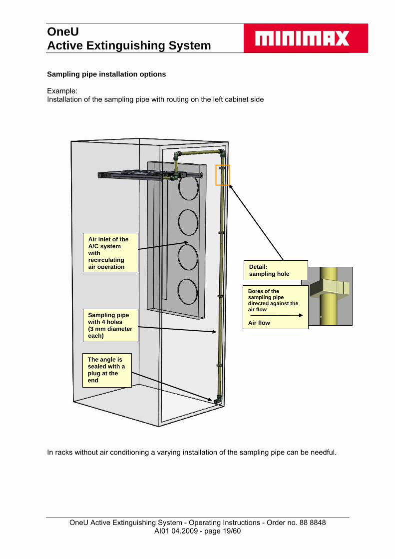
Sampling pipe installation options Example: Installation of the sampling pipe with routing on the left cabinet side
AI01 04.2009 - page 19/60
Air inlet of the A/C system with recirculating air operation
Detail:
sampling hole
Bores of the sampling pipe directed against the air flow
Sampling pipe with 4 holes (3 mm diameter each)
Air flow
The angle is
sealed with a plug at the end
In racks without air conditioning a varying installation of the sampling pipe can be needful.

OneU Active Extinguishing System
OneU Active Extinguishing System - Operating Instructions - Order no. 88 8848
Installation of the sampling pipe
b
1 2
4
c
5
a
b
c
3
Installation of the sampling pipe 1) Mark the insertion depth (a) of the pipe (b)
(use guiding line at the pipe angle! Insertion depth (a) approx. 33 mm (1.30 inches)) 2) Insert pipe loosely 3) Press in the pipe strongly until the stop can be heard and felt and up to the marking (b) Removal of the sampling pipe 4) Press the fixing element (c) down
(only visible as a ring from the outside) 5) Pull out the pipe with the fixing element (c) pressed down
AI01 04.2009 - page 20/60

OneU Active Extinguishing System
OneU Active Extinguishing System - Operating Instructions - Order no. 88 8848
3.3 Installation and commissioning of additional electric devices After the proper installation and commissioning of the OneU Active Extinguishing System additional electric devices can be connected.
Caution! Connection of additional electric devices: For the connection of additional electric devices the following information must always be observed: It is possible for an alarm to be triggered during commissioning!
It must be ensured that any controls downstream from the device (e.g. additional extinguishing systems or transmitted messages) have been switched off beforehand!
Before the functional test the door must be opened to block the extinguishing action. This must be checked via the flashing green operating LED and the indication "extinguishing system blocked". No fire message (red LED) may be indicated before the blocking is cancelled by closing the doors, otherwise the extinguishing action will be initiated!
The conditions must be checked in accordance with the commissioning and test report
3.3.1 External alarm devices
External alarm devices, e.g. flashing lights and/or alarm horns (see also chapter spare parts and accessories) can be connected to the relay outputs pre- and main alarm (see 2.4.4 relay outputs). That max. current with 30 V DC amounts to 0.5 amp.
3.3.2 Push button for manual release
To connect the push button for manual release the sequence in the commissioning and test report (see 7.1) must be observed.
AI01 04.2009 - page 21/60

OneU Active Extinguishing System
OneU Active Extinguishing System - Operating Instructions - Order no. 88 8848
3.4 Alarms and faults
3 3
412
The correct operating state of the OneU Active Extinguishing System is indicated by a permanently illuminated green operating LED (1). If a fire alarm or faults occur, they are indicated on the LCD display (2) and by fault LED (3) or alarm LED (4). The OneU Active Extinguishing System shall therefore be installed in a clearly visible location and monitored by an overriding system, if necessary.
3.4.1 Alarm and fault messages
Alarm messages The OneU Active Extinguishing System can implement two alarm levels with different indications and controls via two sensors responding at different sensitivities. The respective indications and their meanings are explained in the table "LCD display indications" below. Fault messages The OneU Active Extinguishing System monitors the most important functions itself. Faults are indicated and can be queried via the potential-free contact. If the door of the protected cabinet is non-transparent and therefore the display is not readable optionally possible faults can transmitted via dry contacts to a superordinated place to be read off from there. The respective indications and their meanings are explained in the table "LCD display indications" below.
Caution! In case of a fault the proper functioning of the device is not guaranteed. If a fault message arrives it might not be possible to detect and extinguish a fire! Therefore, the cause of the fault message must be immediately removed!
Caution! Before the functional test the door must be opened to block the extinguishing action. This must be checked via the flashing operating LED and the indication "extinguishing system blocked". No fire message (red LED) may be indicated before the blocking is cancelled by closing the doors, otherwise the extinguishing action will be initiated!
AI01 04.2009 - page 22/60

OneU Active Extinguishing System
OneU Active Extinguishing System - Operating Instructions - Order no. 88 8848
3.5 Display and control elements To display the current device state the extinguishing system has an LCD with background illumination and four LEDs to indicate collective conditions. Operation is via four keys on the front.
Reset
Reset- + - +
Status OK
*
LCDdisplay
'Down' key
'Collective fault' LED
PS* fault LED
'Reset PS' key
'Up' key
Operation LED
'Alarm' LED
'Reset' key
Figure 1: Display and control elements *PS = Power Supply
3.5.1 LED indications
The collective indications are implemented via four LEDs on the front. These are activated in accordance with the indication types in Table 1.
Type of indication
Activation
off LED is permanently off
flashing LED is energised every 2 seconds for 200 ms (0.2 secs)
blinking LED is alternately on for 0.5 seconds and off for 0.5 seconds
on LED is permanently on
Table 1: LED indication types
AI01 04.2009 - page 23/60
OneU Active Extinguishing System
OneU Active Extinguishing System - Operating Instructions - Order no. 88 8848
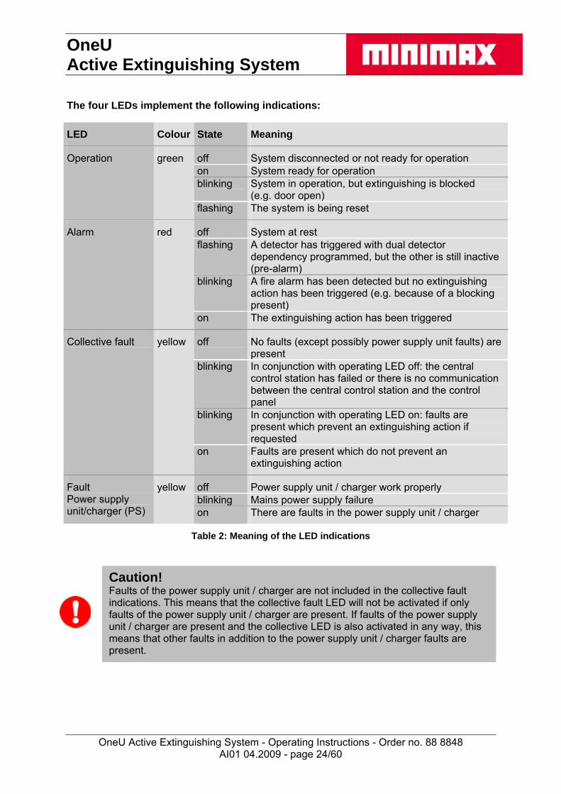
The four LEDs implement the following indications:
LED Colour State Meaning
off System disconnected or not ready for operation on System ready for operation blinking System in operation, but extinguishing is blocked
(e.g. door open)
Operation green
flashing The system is being reset
off System at rest flashing A detector has triggered with dual detector
dependency programmed, but the other is still inactive (pre-alarm)
blinking A fire alarm has been detected but no extinguishing action has been triggered (e.g. because of a blocking present)
Alarm red
on The extinguishing action has been triggered
off No faults (except possibly power supply unit faults) are present
blinking In conjunction with operating LED off: the central control station has failed or there is no communication between the central control station and the control panel
blinking In conjunction with operating LED on: faults are present which prevent an extinguishing action if requested
Collective fault yellow
on Faults are present which do not prevent an extinguishing action
off Power supply unit / charger work properly blinking Mains power supply failure
Fault Power supply unit/charger (PS)
yellow
on There are faults in the power supply unit / charger
Table 2: Meaning of the LED indications
Caution! Faults of the power supply unit / charger are not included in the collective fault indications. This means that the collective fault LED will not be activated if only faults of the power supply unit / charger are present. If faults of the power supply unit / charger are present and the collective LED is also activated in any way, this means that other faults in addition to the power supply unit / charger faults are present.
AI01 04.2009 - page 24/60
OneU Active Extinguishing System
OneU Active Extinguishing System - Operating Instructions - Order no. 88 8848
AI01 04.2009 - page 25/60
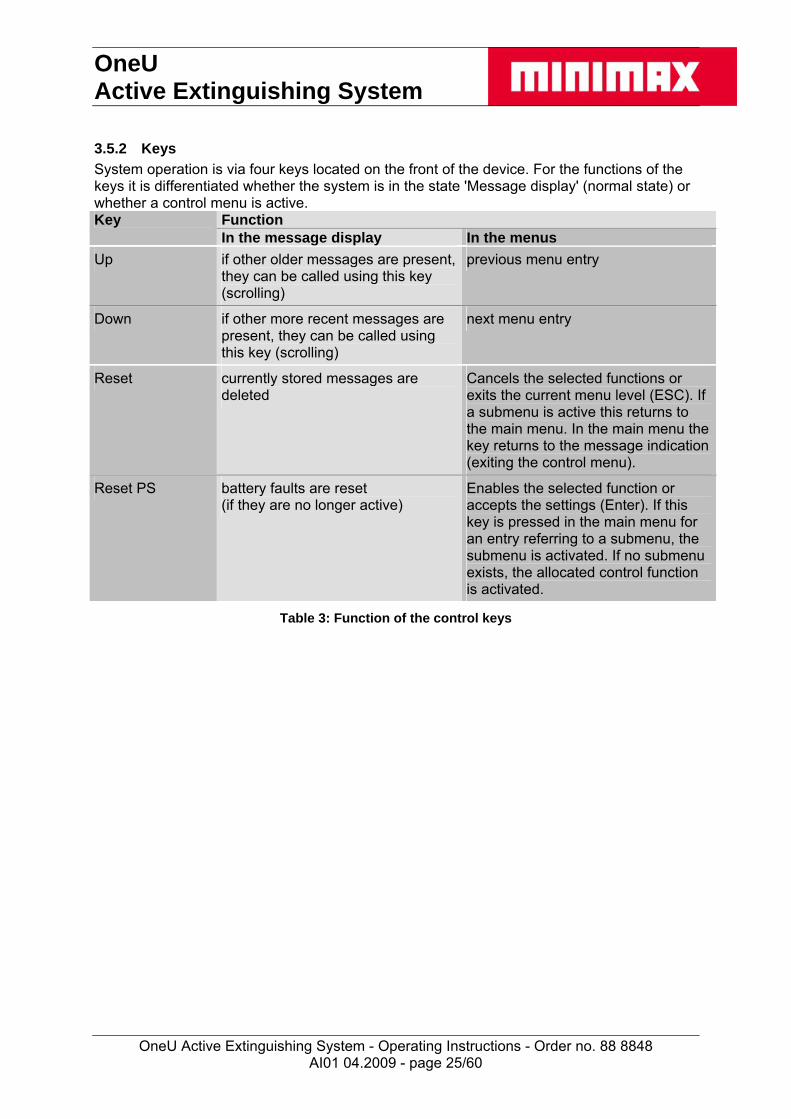
3.5.2 Keys
System operation is via four keys located on the front of the device. For the functions of the keys it is differentiated whether the system is in the state 'Message display' (normal state) or whether a control menu is active.
Function Key In the message display In the menus
Up if other older messages are present, they can be called using this key (scrolling)
previous menu entry
Down if other more recent messages are present, they can be called using this key (scrolling)
next menu entry
Reset currently stored messages are deleted
Cancels the selected functions or exits the current menu level (ESC). If a submenu is active this returns to the main menu. In the main menu the key returns to the message indication (exiting the control menu).
Reset PS battery faults are reset (if they are no longer active)
Enables the selected function or accepts the settings (Enter). If this key is pressed in the main menu for an entry referring to a submenu, the submenu is activated. If no submenu exists, the allocated control function is activated.
Table 3: Function of the control keys

OneU Active Extinguishing System
OneU Active Extinguishing System - Operating Instructions - Order no. 88 8848
3.5.3 LCD display
The LCD display is used to display the individual current messages in text format. The LCD is also used to permit the menu-guided control of the system. Message display Normal state In the normal state of the message display the most recent current message is displayed in the LCD (Figure 2).
4Extinction successful
12.06.07 14:32:48
Message number= number of messagescurrently present
Other older messagesare present which canbe called using the"Up" key
Message text
Figure 2: Normal state of the message display
If no current message is present, the message in is shown in the LCD.
Status OK
* Figure 3: Display without messages
To indicate operability the character '*' runs from left to right through the screen in the lowest line. As soon as at least one message is present, the display automatically changes to the normal state of the message display. Scrolling through messages If more than one current message are present, the individual messages can be viewed (scrolling) using the arrow keys ('Up' and 'Down'). The message display then shows a symbol indicating that other more recent events then the one currently being displayed are present (Figure 4).
AI01 04.2009 - page 26/60
OneU Active Extinguishing System
OneU Active Extinguishing System - Operating Instructions - Order no. 88 8848
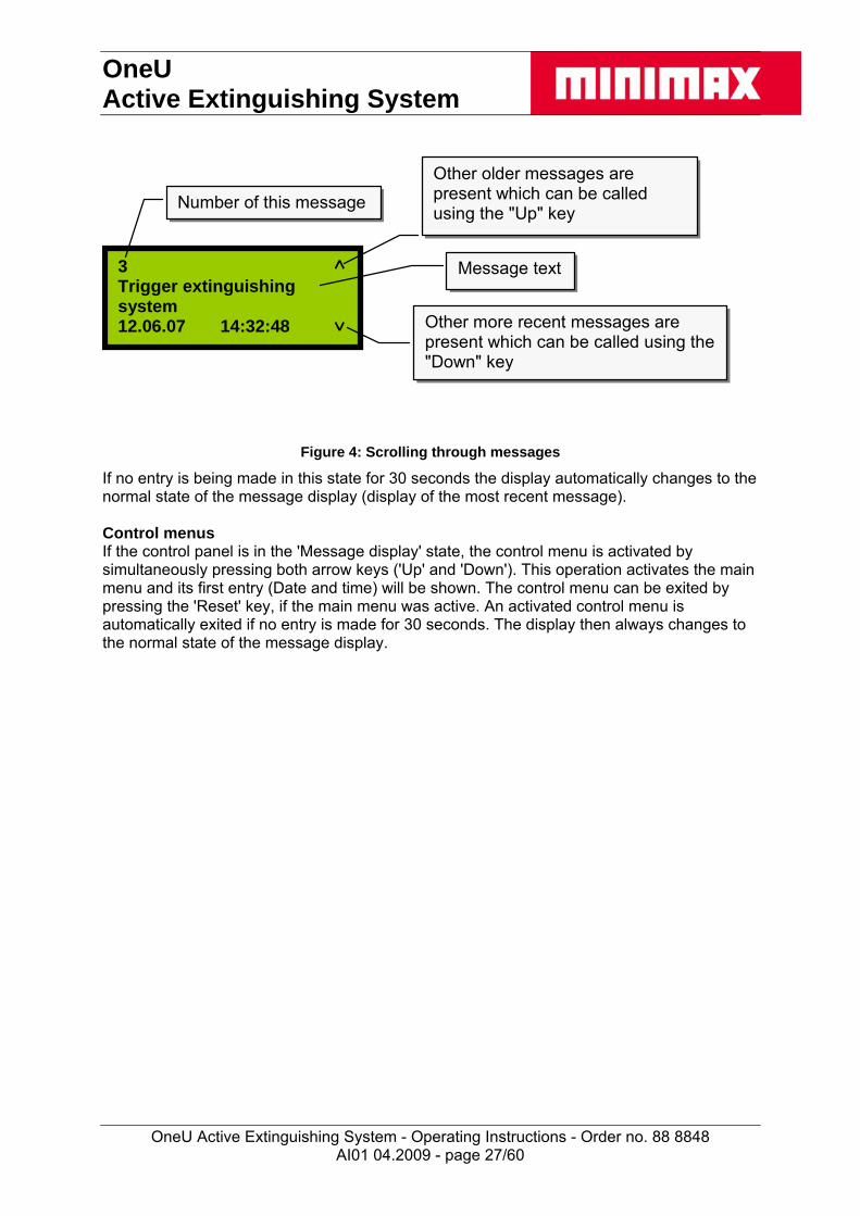
3Trigger extinguishingsystem12.06.07 14:32:48
Number of this message
Other older messages arepresent which can be calledusing the "Up" key
Message text
Other more recent messages arepresent which can be called using the"Down" key
Figure 4: Scrolling through messages
If no entry is being made in this state for 30 seconds the display automatically changes to the normal state of the message display (display of the most recent message). Control menus If the control panel is in the 'Message display' state, the control menu is activated by simultaneously pressing both arrow keys ('Up' and 'Down'). This operation activates the main menu and its first entry (Date and time) will be shown. The control menu can be exited by pressing the 'Reset' key, if the main menu was active. An activated control menu is automatically exited if no entry is made for 30 seconds. The display then always changes to the normal state of the message display.
AI01 04.2009 - page 27/60

OneU Active Extinguishing System
OneU Active Extinguishing System - Operating Instructions - Order no. 88 8848
Main menu Control function " Date and time set":
Date / time
previous exit menumenu item
next select functionmenu item
Reset
Reset
Control function "View event memory":
Event memory
previous exit menu menu item next select function menu item
Reset
Reset
Submenu "Air flow calibration":
Air flow calibration
previous exit menu menu item next activate menu item submenu
Reset
Reset
Control function "Lamp test":
Lamp test
previous exit menu menu item next select function menu item
Reset
Reset
Submenu "Version query":
Version information
previous exit menu menu item next activate menu item submenu
Reset
Reset
Submenu "Battery change":
Battery change
previous exit menumenu item
next select functionmenu item
Reset
Reset
AI01 04.2009 - page 28/60
OneU Active Extinguishing System
OneU Active Extinguishing System - Operating Instructions - Order no. 88 8848
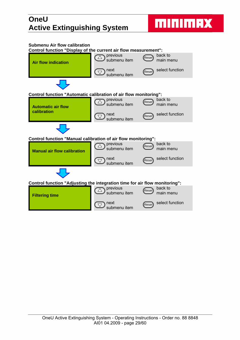
Submenu Air flow calibration Control function "Display of the current air flow measurement":
Air flow indication
previous back to submenu item main menu next select function submenu item
Reset
Reset
Control function "Automatic calibration of air flow monitoring":
Automatic air flow calibration
previous back to submenu item main menu next select function submenu item
Reset
Reset
Control function "Manual calibration of air flow monitoring":
Manual air flow calibration
previous back to submenu item main menu next select function submenu item
Reset
Reset
Control function "Adjusting the integration time for air flow monitoring":
Filtering time
previous back to submenu item main menu next select function submenu item
Reset
Reset
AI01 04.2009 - page 29/60

OneU Active Extinguishing System
OneU Active Extinguishing System - Operating Instructions - Order no. 88 8848
Submenu Version information Control function "Querying the firmware version":
Firmware version
previous back to submenu item main menu next select function submenu item
Reset
Reset
Control function "Querying the version of the control panel software":
Control panel version
previous back to submenu item main menu next select function submenu item
Reset
Reset
Control function "Querying the BIOS version":
BIOS version
previous back to submenu item main menu next select function submenu item
Reset
Reset
AI01 04.2009 - page 30/60

OneU Active Extinguishing System
OneU Active Extinguishing System - Operating Instructions - Order no. 88 8848
Description of the menu functions Querying the firmware version
Firmware version OneU-CPU 00.00.00.14 23.03.2007
back to back to menu menu back to back to menu menu
Reset
Reset
The following information is shown: device name, version number and date of version creation. Querying the version of the control panel software
Control panel version OneU BT 00.00.00.02 12.02.07
back to back to menu menu back to back to menu menu
Reset
Reset
The following information is shown: device name, version number and date of version creation. Querying the BIOS version
BIOS version 01.00.00 (03) HW: 00400000
back to back to menu menu back to back to menu menu
Reset
Reset
The following information is shown: version number and hardware ID.
AI01 04.2009 - page 31/60

OneU Active Extinguishing System
OneU Active Extinguishing System - Operating Instructions - Order no. 88 8848
Set date / time Before selecting a position
28.03.07 08:00:43
>
without cancelfunction function
select position take overto be changed actual value
Reset
Reset
After the activation of the function the current set-up is indicated. In order to make a change, the position to be changed must be selected. (Arrow key 'down'). Changing a selected position
28.03.07 08:00:43
>
count up cancelselected position function
select position take overto be changed actual value
Reset
Reset
The selected position can be increased by one with the arrow key 'up'. If the indication reaches the highest value for this position, it jumps to the lowest value with the next confirmation of the arrow key 'up'. If the arrow key 'up' is pressed for longer than 3 seconds, the value runs upward automatically. Due to the type of communication between main processor and control panel there is a small time delay between key actuation and the system’s reaction. This leads to the fact that when releasing a before permanently pressed key, the value still continues to increase by approx. 2. Only now the automatic function is deactivated.
So that the adjusted values become effective, they must be taken over (key RESET PS).
AI01 04.2009 - page 32/60

OneU Active Extinguishing System
OneU Active Extinguishing System - Operating Instructions - Order no. 88 8848
View event memory The display of messages from the event memory is identical to the message display of the system. To indicate that this is a display from memory the text 'EMEM' is shown at the top right. Unlike in the message display, messages are also entered in the event memory if a state causing a message has been removed. The display of the current message is either by way of a correspondingly different text message (Figure 5) or using the same message plus
the symbol for current messages.
162 EMEMDoor contact at rest
12.06.07 14:32:48
162 EMEMTrigger extinguishingsystem12.06.07 14:32:48
Figure 5: current message 1 Figure 6: current message 2
The number of the message is numbered from the start of the current event memory. I.e. the oldest event still present in the memory has the number 1. If the event memory is full, the next event overwrites the so far oldest event. During the next display of the event memory the event previously carrying the number 2 now carries the number 1 (the stored events move down to allow the new event to be inserted at the top). The numbering in the event memory has no relation to the number shown for the event in the message display when the event was still current. In the display of the event memory one can change from any entry to the chronologically oldest event by simultaneously pressing the two arrow keys 'UP' and 'down'. Likewise the key 'RESET EV' always leads to the chronologically recent event. If one keeps the respective arrow key longer pressed while scrolling, the display continues to run automatically into the selected direction, as long as the key remains pressed. Display if no entries are present in the event memory
EMEM- - -
exit exit display display exit exit display display
Reset
Reset
Display of the most recent event
162 EMEMDoor contact at rest
12.06.07 14:32:48
to previous exitmessage display
no nofunction function
Reset
Reset
By activating this control function "View event memory" the most recent message in time will always be displayed. Changing to older messages is possible using the arrow key "Up". The symbol at the top right of the display indicates that older messages are present.
AI01 04.2009 - page 33/60
OneU Active Extinguishing System
OneU Active Extinguishing System - Operating Instructions - Order no. 88 8848
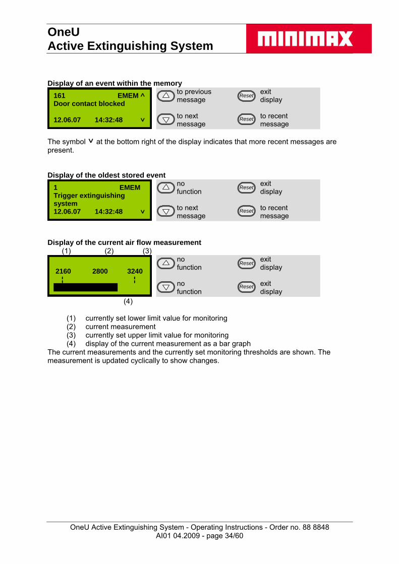
Display of an event within the memory
161 EMEMDoor contact blocked
12.06.07 14:32:48
to previous exitmessage display
to next to recentmessage message
Reset
Reset
The symbol at the bottom right of the display indicates that more recent messages are present.
Display of the oldest stored event
1 EMEMTrigger extinguishingsystem12.06.07 14:32:48
no exitfunction display
to next to recentmessage message
Reset
Reset
Display of the current air flow measurement (1) (2) (3)
2160 2800 3240 ¦ ¦
no exit function display no exit function display
Reset
Reset
(4)
(1) currently set lower limit value for monitoring (2) current measurement (3) currently set upper limit value for monitoring (4) display of the current measurement as a bar graph
The current measurements and the currently set monitoring thresholds are shown. The measurement is updated cyclically to show changes.
AI01 04.2009 - page 34/60
OneU Active Extinguishing System
OneU Active Extinguishing System - Operating Instructions - Order no. 88 8848
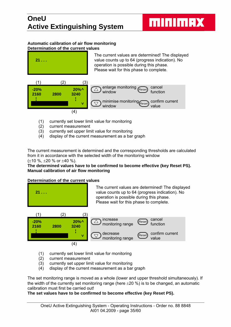
Automatic calibration of air flow monitoring Determination of the current values
21 . . .
The current values are determined! The displayed value counts up to 64 (progress indication). No operation is possible during this phase. Please wait for this phase to complete.
(1) (2) (3)
-20% 20% 2160 2800 3240 ¦ ¦
enlarge monitoring cancel window function minimise monitoring confirm current window value
Reset
Reset
(4)
(1) currently set lower limit value for monitoring (2) current measurement (3) currently set upper limit value for monitoring (4) display of the current measurement as a bar graph
The current measurement is determined and the corresponding thresholds are calculated from it in accordance with the selected width of the monitoring window (10 %, 20 % or 40 %). The determined values have to be confirmed to become effective (key Reset PS). Manual calibration of air flow monitoring Determination of the current values
21 . . .
The current values are determined! The displayed value counts up to 64 (progress indication). No operation is possible during this phase. Please wait for this phase to complete.
(1) (2) (3)
-20% 20% 2160 2800 3240 ¦ ¦
increase cancel monitoring range function decrease confirm current monitoring range value
Reset
Reset
(4)
(1) currently set lower limit value for monitoring (2) current measurement (3) currently set upper limit value for monitoring (4) display of the current measurement as a bar graph
The set monitoring range is moved as a whole (lower and upper threshold simultaneously). If the width of the currently set monitoring range (here 20 %) is to be changed, an automatic calibration must first be carried out! The set values have to be confirmed to become effective (key Reset PS).
AI01 04.2009 - page 35/60

OneU Active Extinguishing System
OneU Active Extinguishing System - Operating Instructions - Order no. 88 8848
Adjusting the integration time for air flow monitoring (filtering time)
3s
increase filtering cancel time function decrease filtering confirm current time value
Reset
Reset
If an arrow key is held pressed for more than 3 seconds, the value automatically changes up or down. Due to the communication method between the main processor and the control panel there is a small delay between pressing the key and the system response. This results in the value still being increased or reduced by approx. 2 when a key is released which was previously held down. The automatic function is only disabled afterwards. Simultaneous pressing of the keys ▲ and ▼ sets the value to 0. The set value has to be confirmed to become effective (key Reset PS). Lamp test All segments of the LCD are blanked in black and all LEDs are switched on permanently.
exit test exit test display display exit test exit test display display
Reset
Reset
The lamp test is exited when any key is pressed. If no key is pressed for more than 5 seconds, the lamp test is automatically exited.
AI01 04.2009 - page 36/60

OneU Active Extinguishing System
OneU Active Extinguishing System - Operating Instructions - Order no. 88 8848
Battery change The period of operation of the batteries is monitored by the system. If it exceeds the maximally permissible time, an appropriate message is displayed and the system goes into the failure mode. In order to reset this monitoring after a battery change, the function ‘battery change’ must be called up. After the start of the function the inquiry takes place:
yesBatteries werechanged? no
confirm cancelchange function
cancel cancelfunction function
Reset
Reset
If this question is answered with ‚yes‘, the resetting of the operating hours meter must be confirmed in the following dialogue:
Please confirmbattery change with‘Reset PS‘!
cancel cancelfunction function
cancel carry outfunction function
Reset
Reset
If the function was carried out the following confirmation message appears:
Battery changewas saved.
back to back tomenu menu
back to back tomenu menu
Reset
Reset
After this message the operating hours meter of the batteries is reset, so that the entire maximum period of operation is available again. A failure message with the request to change the batteries eventually displayed before is reset thereafter. If the function is discontinued in any position, a warning message appears:
Battery change wasnot confirmed!
back to back tomenu menu
back to back tomenu menu
Reset
Reset
If this message appears, the operating hours meter of the batteries was not reset, it keeps running from the temporally last condition. A failure message with the request to change the batteries eventually displayed before is not reset thereafter.
AI01 04.2009 - page 37/60

OneU Active Extinguishing System
OneU Active Extinguishing System - Operating Instructions - Order no. 88 8848
Operating hours meter Apart from the monitoring of the operation hours of the batteries the system evenly monitors the period of operation since the last maintenance. If this exceeds the maximum maintenance interval, a failure message is generated (indication by LED "collective error" and triggering of relay "collective error"). For resetting this message a fabricator reset must be carried out. For this purpose the housing of the OneU must be opened. On the CPU board the key 'Reset' is to be pressed for longer than 3 seconds. Afterwards the failure message to the maintenance interval is deleted and the operation hours meter of the system reset. This resetting does not have any influence on the monitoring of the period of operation of the batteries.
Attention! Both the operating hours meter for the maintenance interval and the operating hours meter for the batteries are based on the inserted real-time clock. Adjusting this clock (control menu date / time) will affect thereby the monitoring of the periods of operation!
3.5.4 LCD display - List of messages
For the following conditions messages will be displayed on the LCD display: Display text Display text meaning
Fire Both sensors have triggered a fire alarm or on of them triggered a fire alarm and the other one reported a fault without triggering the extinguishing action.
Manual release An externally connected push button for manual release has been released.
Manual release fault An externally connected push button for manual release is faulty or the line to it is faulty.
External blocking The extinguishing release is blocked by a door contact switch or an external contact.
Pre-alarm The first sensor has detected a particle with typical fire characteristics in the intake air.
Fire alarm detector 1 The first sensor has detected a particle with typical fire characteristics in the intake air.
Fire alarm detector 2 The second sensor has detected a particle with typical fire characteristics in the intake air.
Blocking by door contact A cabinet door is open and the door contact for suppressing the extinguishing action is enabled, the extinguishing system cannot be triggered. or A terminating resistor for the door switch is missing
Door contact fault A connected door contact switch is faulty or the line to it is faulty.
Mains failure The mains voltage is missing or the power supply unit is faulty.
AI01 04.2009 - page 38/60
OneU Active Extinguishing System
OneU Active Extinguishing System - Operating Instructions - Order no. 88 8848
AI01 04.2009 - page 39/60
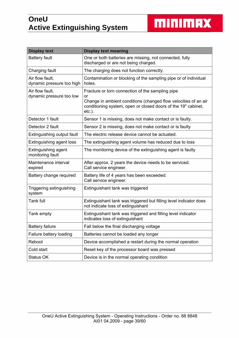
Display text Display text meaning
Battery fault One or both batteries are missing, not connected, fully discharged or are not being charged.
Charging fault The charging does not function correctly.
Air flow fault, dynamic pressure too high
Contamination or blocking of the sampling pipe or of individual holes.
Air flow fault, dynamic pressure too low
Fracture or torn connection of the sampling pipe or Change in ambient conditions (changed flow velocities of an air conditioning system, open or closed doors of the 19" cabinet, etc.).
Detector 1 fault Sensor 1 is missing, does not make contact or is faulty.
Detector 2 fault Sensor 2 is missing, does not make contact or is faulty
Extinguishing output fault The electric release device cannot be actuated.
Extinguishing agent loss The extinguishing agent volume has reduced due to loss
Extinguishing agent monitoring fault
The monitoring device of the extinguishing agent is faulty
Maintenance interval expired
After approx. 2 years the device needs to be serviced. Call service engineer.
Battery change required Battery life of 4 years has been exceeded. Call service engineer.
Triggering extinguishing system
Extinguishant tank was triggered
Tank full Extinguishant tank was triggered but filling level indicator does not indicate loss of extinguishant
Tank empty Extinguishant tank was triggered and filling level indicator indicates loss of extinguishant
Battery failure Fall below the final discharging voltage
Failure battery loading Batteries cannot be loaded any longer
Reboot Device accomplished a restart during the normal operation
Cold start Reset key of the processor board was pressed
Status OK Device is in the normal operating condition
OneU Active Extinguishing System
OneU Active Extinguishing System - Operating Instructions - Order no. 88 8848
4. Behaviour during a fire
Caution! This information does not replace the locally prescribed behaviour during a fire in any way but serves as additional information about the behaviour during alarms/fires or triggering of the extinguishing system in a cabinet protected by a OneU Active Extinguishing System!
Measures in case of an alarm in a cabinet protected by a OneU Active Extinguishing System: Always keep the cabinet doors closed during the hold time (10 minutes). If the
concentration required for extinguishing drops due to ventilation, any still existing source of ignition might flare up again.
If no fire or smoke can be seen, the cabinet can be ventilated with extinguishing aids (e.g. carbon dioxide fire extinguisher) at the ready.
Release of the OneU Active Extinguishing System The release of the OneU Active Extinguishing System takes place immediately after the fire alarm. A fire alarm is triggered by the actuation of both automatic fire detectors or operation of the push button for manual release. If the extinguishing system is triggered manually via the push button for manual release, the release takes place immediately without time delay.
Caution! The presence in rooms flushed with the extinguishing agent Novec™ 1230 is harmless but should be avoided, because smoke development may endanger life due to toxic combustion products.
AI01 04.2009 - page 40/60

OneU Active Extinguishing System
OneU Active Extinguishing System - Operating Instructions - Order no. 88 8848
AI01 04.2009 - page 41/60
5. Control, service, maintenance and repair after release The operator carries out the regular visual inspections at the device himself. The maintenance and repair of the device is carried out by the Minimax Service or a specialist company authorised by Minimax. A specialist company authorised for maintenance and fault removal is a company whose employees have been trained by Minimax in the OneU Active Extinguishing System. Normally this is a member of the installation company or a specially trained employee of the operator or a specialist company commissioned by him. In case of improper handling and faulty or missing regular inspections and maintenance Minimax does not accept any liability.
5.1 Regular inspections by the operator Daily inspections (operator) No fault may be present in the OneU Active Extinguishing System.
(operating state without fault or alarm: green operation LED is on, no yellow fault LED is on or flashing). Any faults present must be recorded and removal must be initiated.
Daily inspections may be omitted if it can be ensured that any faults are safely detected elsewhere. Monthly inspection (operator) Sampling pipe and extinguishing nozzle must be free of external damage and the nozzle
must be free of contamination and obstacles in the spray. Sampling pipe connections must not be disconnected Display air flow and compare with the value from the commissioning report to detect any contamination. The max. deviation to the target value must not exceed 10 %. Quarterly inspection (operator) This should additionally investigate any constructive modifications (especially with regard to the air tightness of the cabinet: the air exchange rate of the switch cabinet system to be protected must not be greater than 10 % within 20 min) or changes in use, and the device should be checked for the proper operation of the alarm, fault and control functions.

OneU Active Extinguishing System
OneU Active Extinguishing System - Operating Instructions - Order no. 88 8848
5.2 Tests, maintenance and repairs 5.2 Tests, maintenance and repairs
AI01 04.2009 - page 42/60
Note: Minimax Service-Hotline Service-Hotline Germany: 01805.663676 (14 ct./min. via fixed telephone network of DTAG) Service-Hotline others: ++49.4531.8030 ce-Hotline others: ++49.4531.8030 The addresses of the regional offices are listed on the www.minimax.de The addresses of the regional offices are listed on the www.minimax.de
Caution! During maintenance work at the device an alarm may / should be triggered! It must be ensured that any controls downstream from the device (e.g. transmitted messages or shut-off device) have been switched off/bridged beforehand!
Annual maintenance (Minimax or specialist company) Annual maintenance (Minimax or specialist company) Visual inspection, complete service (e.g. test and, if necessary, clean sampling pipe and extinguishing nozzle, check cover seal, replace filter for air flow sensor, if necessary, check air flow calibration and adjust, if necessary) plus operational check.
Visual inspection, complete service (e.g. test and, if necessary, clean sampling pipe and extinguishing nozzle, check cover seal, replace filter for air flow sensor, if necessary, check air flow calibration and adjust, if necessary) plus operational check. The history memory must be checked for errors (see 3.5.3 “View event memory”). The history memory must be checked for errors (see 3.5.3 “View event memory”). Biennial maintenance (Minimax or specialist company) Biennial maintenance (Minimax or specialist company) At least every two years the OneU Active Extinguishing System must be serviced by Minimax Service or a specialist company authorised by Minimax. This service requirement is indicated in the display.
At least every two years the OneU Active Extinguishing System must be serviced by Minimax Service or a specialist company authorised by Minimax. This service requirement is indicated in the display. During this maintenance the system is fully tested and, if necessary, returned to the target condition. Non-observance of these intervals may cause faults or false alarms and subsequent false extinguishing.
During this maintenance the system is fully tested and, if necessary, returned to the target condition. Non-observance of these intervals may cause faults or false alarms and subsequent false extinguishing. After 2 years, in the context of the second 2 biennial maintenance, the batteries for the emergency power supply must be replaced. After 2 years, in the context of the second 2 biennial maintenance, the batteries for the emergency power supply must be replaced. For the sensor inserts integrated in the OneU active extinguishing system a total lifetime of 10 years is recommended when used within dry areas, free from dust and corrosive atmospheres. Regular inspections, maintenance, if necessary cleaning and calibration are presupposed.
For the sensor inserts integrated in the OneU active extinguishing system a total lifetime of 10 years is recommended when used within dry areas, free from dust and corrosive atmospheres. Regular inspections, maintenance, if necessary cleaning and calibration are presupposed. In individual cases, depending upon site conditions or type of sensor, shorter intervals for replacement can be necessary. In individual cases, depending upon site conditions or type of sensor, shorter intervals for replacement can be necessary.
Caution! Fault indication for battery capacity: The fault indication of the available battery capacity responds to a remaining capacity of less than approx. 70%. With a breplacement or with the initial commissioning it can come to the fact that the message "Battery not full" appears, since the new batteries were stored for a too long time. This indication disappears only, when a battery capacity of > 70 % is reached.
attery
5.3 Recommissioning after release 5.3 Recommissioning after release The short term recommissioning is made by the Minimax service. The short term recommissioning is made by the Minimax service.
OneU Active Extinguishing System
OneU Active Extinguishing System - Operating Instructions - Order no. 88 8848
5.4 Notes on transport During the transport of the device with extinguishing agent container and propelling gas cartridge the following special rules must be taken into account. Special notes on transport for overland transportation - ADR UN 0432 DANGEROUS GOODS IN APPARATUS, class 1.4S, is subject to the regulations of the ADR Special notes on transport for sea transportation - IMDG - Code UN 0432 ARTICLES; PYROTECHNIC, class 1.4S, EMS F-B, S-X Special notes on transport for air transportation - IATA DGR UN 0432 ARTICLES; PYROTECHNIC, class 1.4S, Packing instructions 135 The safety data sheets for this device and for Novec™ 1230 by 3M™ must be observed and are included with the device during delivery.
Attention! Prior to the return transport of the complete device or just the tank the activation switch must be switched to blocking. If the complete device is dispatched the batteries have to be switched off.
Packaging Always retain the transport packaging of this device. For maintenance or repair the device may only be sent in the special original transport packaging or an equivalent one. Data of the original shipping package Dimensions w x d x h 865 x 660 x 190 mm (34.08 x 26 x 7.49 inches) Weight approx. 6.9 kg (15.18 lbs)
AI01 04.2009 - page 43/60

OneU Active Extinguishing System
OneU Active Extinguishing System - Operating Instructions - Order no. 88 8848
AI01 04.2009 - page 44/60
6. Technical data Mounting dimensions 19“, 1HE (1 ¾ inch), 620 mm (24.43 inches) deep Material housing sheet metal Weight approx. 17 kg (34.4 lbs) Nominal voltage 100/240V AC, 50/60Hz Emergency power supply approx. 4 h Ambient temperature +10 °C to +35 °C (operation), (50ºF to 95ºF)
-20 °C to +65 °C (storage), (-4ºF to 149ºF) Humidity up to 96 %, non-condensing Protection category IP 20 Connections 1 potential-free change-over contact "pre-alarm"
1 potential-free change-over contact "fire" 1 potential-free change-over contact "extinguishing" 1 potential-free change-over contact "collective fault" 24 V -3/+5 V nominal voltage / 0.5A, resistive load
Displays 1 LCD with clear text display of status messages 1 LED green "operation" 1 LED red "alarm" 1 LED yellow "collective fault" 1 LED yellow "power supply unit/charger fault"
Sensors (2 different scattered light sensors for 2 alarm thresholds)
optical smoke detector (sensitivity: approx. 3.5 %/m light obscuration)
optical smoke detector HS (sensitivity: approx. 0.25 %/m light obscuration)
Sampling pipe glueless connector system, black (outer diameter: 22 mm, inner diameter: 18 mm)
Sampling holes min. 4 sampling holes, diameter: 3 mm (0.12 inches) Air flow monitoring approx. +/-10 % volume flow Protection volume max. 3.0 m3 (105.9 ft3 ) (for airtight cabinets: the air exchange rate of
the switch cabinet system to be protected must not be greater than 10 % within 20 min.)
External devices connection for push button for manual release connection for door contact connection for external signalling devices CAN connector for system networking
Approval electric components meets UL requirements Extinguishing agent container
material: aluminium / steel empty volume: approx. 2.2 l content: 2 litres (= 3.2 kg) Novec™ 1230 extinguishing agent discharge by pressure build-up via propelling
gas cartridge with integrated release device integrated extinguishing agent loss / filling level monitoring
(indication of > 15 % loss)
OneU Active Extinguishing System
OneU Active Extinguishing System - Operating Instructions - Order no. 88 8848
AI01 04.2009 - page 45/60
7 Appendix
7.1 Commissioning Date of commissioning / commissioner: _________________________________ Serial number of the device: _________________________________ Procedure to start-up after installation in accordance with chapter 3.2.2 Connection of the door contact incl. the installation of resistors Calling-up the menu item „air flow calibration“ (at this point the intake pipe has to be
attached): - Simultaneous pressing of the keys „up“ and „down“ - The heading "event memory" appears in the menu - Unique pressing of the key "down", the menu item "air flow calibration" appears - Confirm with the key „reset PS“ - The sub menu item „indication air flow“ appears - Press the key „down“ once - The sub menu item „automatic air flow calibration“ appears
Choosing the sub menu item „automatic air flow calibration“ (see chapter 3.5.3, subject
„sub menu air flow calibration“) Choosing the function via the lower reset button (button „reset PS“) Immediate closing of the door. Waiting until the counter counted up and the air flow is
indicated The lower limit, the upper limit and the current air flow are indicated now Filling in of the current values into following table (the respectively adjusted tolerance is
to be marked with a cross) and confirming by use of the button „reset PS“ (Adjustment with delivery is +/- 40 %)
Tolerance
Lower limit
Current value
Upper limit 40 % 20 % 10 % Initially 10 % should be set as permitted deviation because this setting permits the earliest possible detection of a contamination of the sampling holes. If the air flow reports frequent faults due to the flow conditions, the tolerance can be raised to 20 or 40 %.

OneU Active Extinguishing System
OneU Active Extinguishing System - Operating Instructions - Order no. 88 8848
Check of the alarm function With closed door the device is now ready for use: The green LED glows and in the display "status OK" is indicated. If this is not the case, the key "reset" is to be pressed. After that the green LED flashes twice and messages that were still queued up are reset. Opening the door: The message " extinguishing system blocked" appears and the green
LED flashes. Disabling of the system by pulling the door contact plug at the rear of the device. By this
measure the door switch is set out of function. Now additionally the message "Door contact fault" appears in the display.
Caution! Thus the blocking of the fire extinguishing system is abrogated. An activation of the fire extinguishing system thus also place takes with opened door. A check of the device may only be carried out if no message „Door contact fault“ is on the display.
Release of the device by means of test gas at the final hole of the sampling pipe (spray approx. 2 seconds directly into the sampling hole)
The device now signals "Fire alarm detector 1", "Pre-alarm", "Fire alarm detector 1", "fire" and the red LED flashes
Reset the alarm after 2 minutes at the earliest (in order that the test gas is completely sucked off from the measuring chamber) with the button "reset". The red LED stops flashing and the alarm messages in the display disappear.
Procedure when connecting push buttons for manual release / manual alarm If no push buttons for manual release are to be connected, this point can be ignored. - Connecting the manual alarm acc. to 2.4.2 to outlet manual alarm 10 (see chapter 2.4) - Reset the fault signal that appears during connection with the button "reset". - Releasing the manual alarm: The red LED must flash now and "manual release" and
"fire" must be indicated in the display. - Reset the manual alarm and push the button „reset“. Test of air flow monitoring - Note: To check the air flow monitoring 2 sampling holes must be closed with insulating
tape. After the set filtering time the yellow fault LED must illuminate and the message air flow too low must appear in the display.
- Closing of 2 sampling holes with insulating tape: The message “Air flow fault, dynamic pressure too low” must be appear in the display.
- Remove the insulating tape from the sampling holes again and push the button „reset“: The message “Air flow fault, dynamic pressure too low” is not indicated any longer.
Reactivating the system - The message "fire" may now be indicated in the display no more and the red LED must
not flash any more. - Attach the previously removed door contact plug. Press the button "reset" and close the
door. "status OK" must now be indicated in the display again and the green LED must glow permanently.
AI01 04.2009 - page 46/60
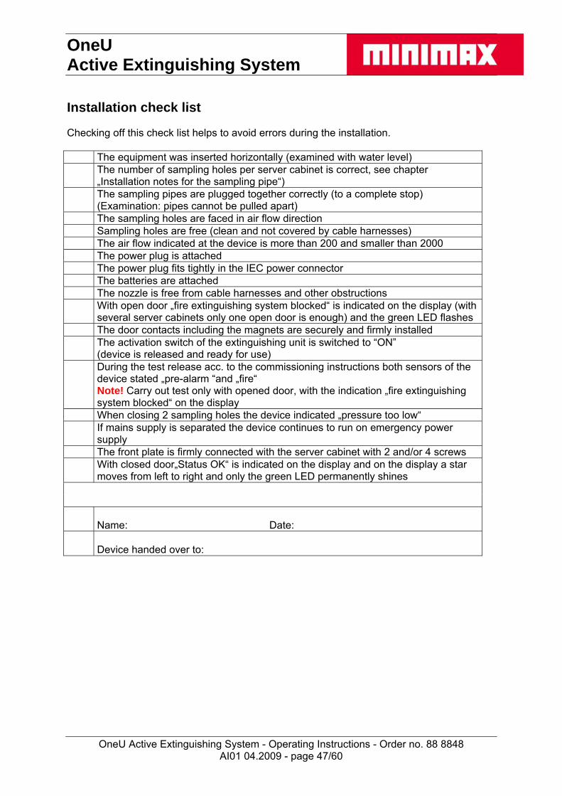
OneU Active Extinguishing System
OneU Active Extinguishing System - Operating Instructions - Order no. 88 8848
AI01 04.2009 - page 47/60
Installation check list Checking off this check list helps to avoid errors during the installation. The equipment was inserted horizontally (examined with water level) The number of sampling holes per server cabinet is correct, see chapter
„Installation notes for the sampling pipe“) The sampling pipes are plugged together correctly (to a complete stop)
(Examination: pipes cannot be pulled apart) The sampling holes are faced in air flow direction Sampling holes are free (clean and not covered by cable harnesses) The air flow indicated at the device is more than 200 and smaller than 2000 The power plug is attached The power plug fits tightly in the IEC power connector The batteries are attached The nozzle is free from cable harnesses and other obstructions With open door „fire extinguishing system blocked“ is indicated on the display (with
several server cabinets only one open door is enough) and the green LED flashes The door contacts including the magnets are securely and firmly installed The activation switch of the extinguishing unit is switched to “ON”
(device is released and ready for use) During the test release acc. to the commissioning instructions both sensors of the
device stated „pre-alarm “and „fire“ Note! Carry out test only with opened door, with the indication „fire extinguishing system blocked“ on the display
When closing 2 sampling holes the device indicated „pressure too low“ If mains supply is separated the device continues to run on emergency power
supply The front plate is firmly connected with the server cabinet with 2 and/or 4 screws With closed door„Status OK“ is indicated on the display and on the display a star
moves from left to right and only the green LED permanently shines
Name: Date:
Device handed over to:

OneU Active Extinguishing System
OneU Active Extinguishing System - Operating Instructions - Order no. 88 8848
AI01 04.2009 - page 48/60
Installation check list Checking off this check list helps to avoid errors during the installation. The equipment was inserted horizontally (examined with water level) The number of sampling holes per server cabinet is correct, see chapter
„Installation notes for the sampling pipe“) The sampling pipes are plugged together correctly (to a complete stop)
(Examination: pipes cannot be pulled apart) The sampling holes are faced in air flow direction Sampling holes are free (clean and not covered by cable harnesses) The air flow indicated at the device is more than 200 and smaller than 2000 The power plug is attached The power plug fits tightly in the IEC power connector The batteries are attached The nozzle is free from cable harnesses and other obstructions With open door „fire extinguishing system blocked“ is indicated on the display (with
several server cabinets only one open door is enough) and the green LED flashes The door contacts including the magnets are securely and firmly installed The activation switch of the extinguishing unit is switched to “ON”
(device is released and ready for use) During the test release acc. to the commissioning instructions both sensors of the
device stated „pre-alarm “and „fire“ Note! Carry out test only with opened door, with the indication „fire extinguishing system blocked“ on the display
When closing 2 sampling holes the device indicated „pressure too low“ If mains supply is separated the device continues to run on emergency power
supply The front plate is firmly connected with the server cabinet with 2 and/or 4 screws With closed door„Status OK“ is indicated on the display and on the display a star
moves from left to right and only the green LED permanently shines
Name: Date:
Device handed over to:

OneU Active Extinguishing System
OneU Active Extinguishing System - Operating Instructions - Order no. 88 8848
AI01 04.2009 - page 49/60
Installation check list Checking off this check list helps to avoid errors during the installation. The equipment was inserted horizontally (examined with water level) The number of sampling holes per server cabinet is correct, see chapter
„Installation notes for the sampling pipe“) The sampling pipes are plugged together correctly (to a complete stop)
(Examination: pipes cannot be pulled apart) The sampling holes are faced in air flow direction Sampling holes are free (clean and not covered by cable harnesses) The air flow indicated at the device is more than 200 and smaller than 2000 The power plug is attached The power plug fits tightly in the IEC power connector The batteries are attached The nozzle is free from cable harnesses and other obstructions With open door „fire extinguishing system blocked“ is indicated on the display (with
several server cabinets only one open door is enough) and the green LED flashes The door contacts including the magnets are securely and firmly installed The activation switch of the extinguishing unit is switched to “ON”
(device is released and ready for use) During the test release acc. to the commissioning instructions both sensors of the
device stated „pre-alarm “and „fire“ Note! Carry out test only with opened door, with the indication „fire extinguishing system blocked“ on the display
When closing 2 sampling holes the device indicated „pressure too low“ If mains supply is separated the device continues to run on emergency power
supply The front plate is firmly connected with the server cabinet with 2 and/or 4 screws With closed door„Status OK“ is indicated on the display and on the display a star
moves from left to right and only the green LED permanently shines
Name: Date:
Device handed over to:

OneU Active Extinguishing System
OneU Active Extinguishing System - Operating Instructions - Order no. 88 8848
AI01 04.2009 - page 50/60
Installation check list Checking off this check list helps to avoid errors during the installation. The equipment was inserted horizontally (examined with water level) The number of sampling holes per server cabinet is correct, see chapter
„Installation notes for the sampling pipe“) The sampling pipes are plugged together correctly (to a complete stop)
(Examination: pipes cannot be pulled apart) The sampling holes are faced in air flow direction Sampling holes are free (clean and not covered by cable harnesses) The air flow indicated at the device is more than 200 and smaller than 2000 The power plug is attached The power plug fits tightly in the IEC power connector The batteries are attached The nozzle is free from cable harnesses and other obstructions With open door „fire extinguishing system blocked“ is indicated on the display (with
several server cabinets only one open door is enough) and the green LED flashes The door contacts including the magnets are securely and firmly installed The activation switch of the extinguishing unit is switched to “ON”
(device is released and ready for use) During the test release acc. to the commissioning instructions both sensors of the
device stated „pre-alarm “and „fire“ Note! Carry out test only with opened door, with the indication „fire extinguishing system blocked“ on the display
When closing 2 sampling holes the device indicated „pressure too low“ If mains supply is separated the device continues to run on emergency power
supply The front plate is firmly connected with the server cabinet with 2 and/or 4 screws With closed door„Status OK“ is indicated on the display and on the display a star
moves from left to right and only the green LED permanently shines
Name: Date:
Device handed over to:

OneU Active Extinguishing System
OneU Active Extinguishing System - Operating Instructions - Order no. 88 8848
AI01 04.2009 - page 51/60
7.2 Spare parts, accessories and consumables + tools S M Item L Order number
Complete Device 0 E OneU Active Extinguishing System 1U 88 8840
Spare parts 2 E Extinguishing tank system complete 88 8841 3 E Set of batteries (2x 12V/ 2.2 Ah) 23 6023 4 E Fire detector head OMX1002C 90 6323 4 E Fire detector head OMX1002C HS 90 6224 4 E Air flow sensor filter 50µm 89 3663 X E Fuse 2.0 A / 250 Volt (power supply unit) 15 0240 X E Fuse F2 3.15 A / 250 Volt 90 3147 X E Fuse F3 0.630 A / 250 Volt 90 7564 X E Terminator 1K8 Ohm, 1/10 watt
(for door contact or push button for manual release) 67 5235
X E Resistor 470 Ohm, 1/10 watt (for door contact or push button for manual release)
67 5223
X E Power cable 90 6083 X E Operating manual (German) 88 8847 X E Operating manual (English) 88 8848
Accessories 0 Z Sampling pipe complete with attachment
clips 90 6795
0 Z Door contact switch, wiring M20x1,5 90 7055 0 Z Alarm combination SONFL1 MX
(flashing light + alarm horn) 90 6508
0 Z Push button for manual release DMX 3000, yellow
88 8845
0 Z Test gas 90 5904 Tools
0 W Pipe cutter 90 5281 0 W FESTO release fork for disconnecting
sampling pipe connections
2 W Phillips screwdriver for cover screws
S = Service level (0= installation / commissioning, 1= device replacement, 2= extinguishing module replacement, 3= wearing parts replacement (e.g. batteries), 4= re-commissioning after release)
M = characteristic (E= spare part, W= tool, Z= accessory) L = storage location / supplier
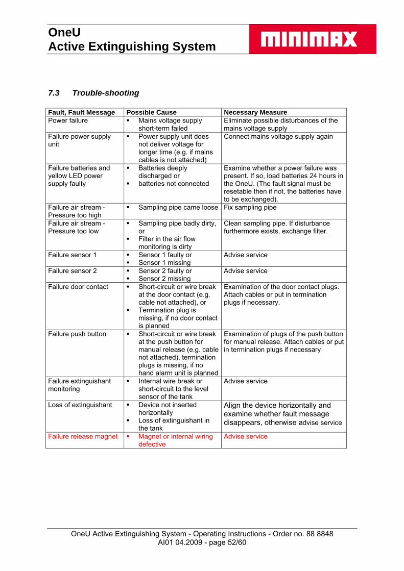
OneU Active Extinguishing System
OneU Active Extinguishing System - Operating Instructions - Order no. 88 8848
AI01 04.2009 - page 52/60
7.3 Trouble-shooting Fault, Fault Message Possible Cause Necessary Measure Power failure Mains voltage supply
short-term failed Eliminate possible disturbances of the mains voltage supply
Failure power supply unit
Power supply unit does not deliver voltage for longer time (e.g. if mains cables is not attached)
Connect mains voltage supply again
Failure batteries and yellow LED power supply faulty
Batteries deeply discharged or
batteries not connected
Examine whether a power failure was present. If so, load batteries 24 hours in the OneU. (The fault signal must be resetable then if not, the batteries have to be exchanged).
Failure air stream - Pressure too high
Sampling pipe came loose Fix sampling pipe
Failure air stream - Pressure too low
Sampling pipe badly dirty, or
Filter in the air flow monitoring is dirty
Clean sampling pipe. If disturbance furthermore exists, exchange filter.
Failure sensor 1 Sensor 1 faulty or Sensor 1 missing
Advise service
Failure sensor 2 Sensor 2 faulty or Sensor 2 missing
Advise service
Failure door contact Short-circuit or wire break at the door contact (e.g. cable not attached), or
Termination plug is missing, if no door contact is planned
Examination of the door contact plugs. Attach cables or put in termination plugs if necessary.
Failure push button Short-circuit or wire break at the push button for manual release (e.g. cable not attached), termination plugs is missing, if no hand alarm unit is planned
Examination of plugs of the push button for manual release. Attach cables or put in termination plugs if necessary
Failure extinguishant monitoring
Internal wire break or short-circuit to the level sensor of the tank
Advise service
Loss of extinguishant Device not inserted horizontally
Loss of extinguishant in the tank
Align the device horizontally and examine whether fault message disappears, otherwise advise service
Failure release magnet Magnet or internal wiring defective
Advise service
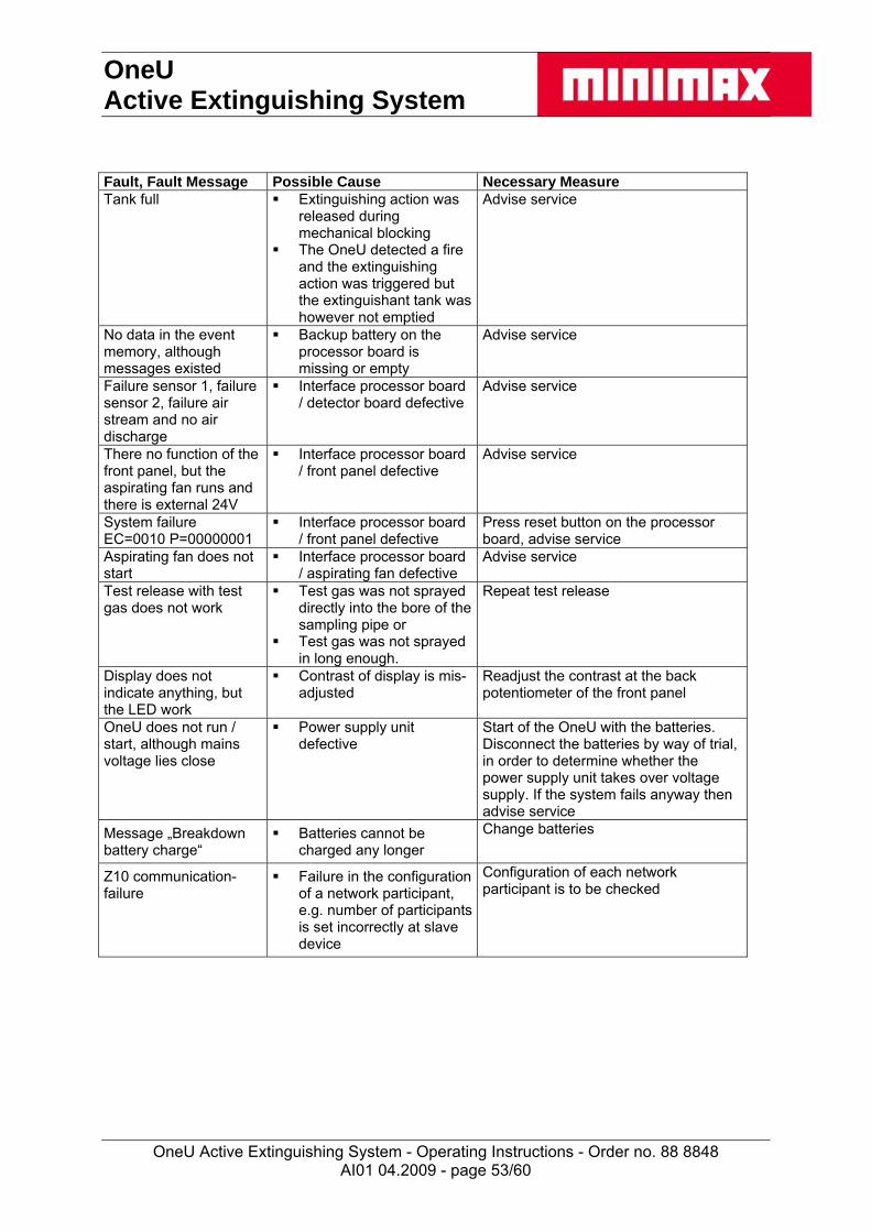
OneU Active Extinguishing System
OneU Active Extinguishing System - Operating Instructions - Order no. 88 8848
AI01 04.2009 - page 53/60
Fault, Fault Message Possible Cause Necessary Measure Tank full Extinguishing action was
released during mechanical blocking
The OneU detected a fire and the extinguishing action was triggered but the extinguishant tank was however not emptied
Advise service
No data in the event memory, although messages existed
Backup battery on the processor board is missing or empty
Advise service
Failure sensor 1, failure sensor 2, failure air stream and no air discharge
Interface processor board / detector board defective
Advise service
There no function of the front panel, but the aspirating fan runs and there is external 24V
Interface processor board / front panel defective
Advise service
System failure EC=0010 P=00000001
Interface processor board / front panel defective
Press reset button on the processor board, advise service
Aspirating fan does not start
Interface processor board / aspirating fan defective
Advise service
Test release with test gas does not work
Test gas was not sprayed directly into the bore of the sampling pipe or
Test gas was not sprayed in long enough.
Repeat test release
Display does not indicate anything, but the LED work
Contrast of display is mis-adjusted
Readjust the contrast at the back potentiometer of the front panel
OneU does not run / start, although mains voltage lies close
Power supply unit defective
Start of the OneU with the batteries. Disconnect the batteries by way of trial, in order to determine whether the power supply unit takes over voltage supply. If the system fails anyway then advise service
Message „Breakdown battery charge“
Batteries cannot be charged any longer
Change batteries
Z10 communication-failure
Failure in the configuration of a network participant, e.g. number of participants is set incorrectly at slave device
Configuration of each network participant is to be checked

OneU Active Extinguishing System
OneU Active Extinguishing System - Operating Instructions - Order no. 88 8848
AI01 04.2009 - page 54/60
7.4 Language settings Changeover of the language for indication and operation The device can communicate in 2 languages, German and English. "German" is pre-set at delivery and can simply be switched by use of a dip switch to "English". The switching is proceeded as follows disconnect the device from mains supply and the battery backup Remove the protective foil Change over the dip-switch no. 4 from position „off“ (German) to „on“ (English) Stick on the protective foil again Take device into operation again
7.5 Cross-linking / Protection of several switch cabinets Cross-linking of the devices For the protection of several control cabinets up to five devices (OneU active fire extinguishing system or OneU DD with OneU ED) can be cross-linked over a bus system. For the cross-linking each time a data and a supply line must be installed.

OneU Active Extinguishing System
OneU Active Extinguishing System - Operating Instructions - Order no. 88 8848
Configuration of the respective devices. Open the cover plate of the device Configuration of the device with adresses (see fig. 1) S4 adjusted to the number 3 (may not be changed!) S5 adjusted to the number 3 (may not be changed!) S6 adjust to the sum of the cross-linked devices S7 adjust to the participant number, which the equipment has within the network
(see list below), with devices that are not cross-linked S7 must be 0! With cross-linked devices the master must always have the participant number 1 (switch S7 on „1 “) Note: On the display the upstream device (master) appears as Z1
Close and bolt cover plate of the device.
S4 S5 S6 S7
AI01 04.2009 - page 55/60
Fig. 1 Configuration of devices by adjusting the switches S6 and S7
Connection power supply and data line At first the mains supply is put on at the master device, then each slave device is attached to the voltage output of the upstream device. Only, if thereafter is no fire message at the display of the master device, the data lines may be attached to the respective upstream devices. Checking the network: After the network is set up completely a message has to be generated at each device. Each message must be examined at the master device. It is recommended for it to operate the door contact of each device. Operating the respective devices The operation and display of the current condition of the fire extinguishing system takes place via the master with the identification 1 (OneU active fire extinguishing system or OneU DD). On its LCD display the individual devices, after being selected, are indicated. The attached device indicated by the message is to be identified as follows by its individual identifier (Z2 to Z5): Identifier / participant Device, to which the message refers Z1 OneU active fire extinguishing system or OneU DD
(each time master!) Z2 OneU ED extinguishing system 1 Z3 OneU ED extinguishing system 2 Z4 OneU ED extinguishing system 3 Z5 OneU ED extinguishing system 4
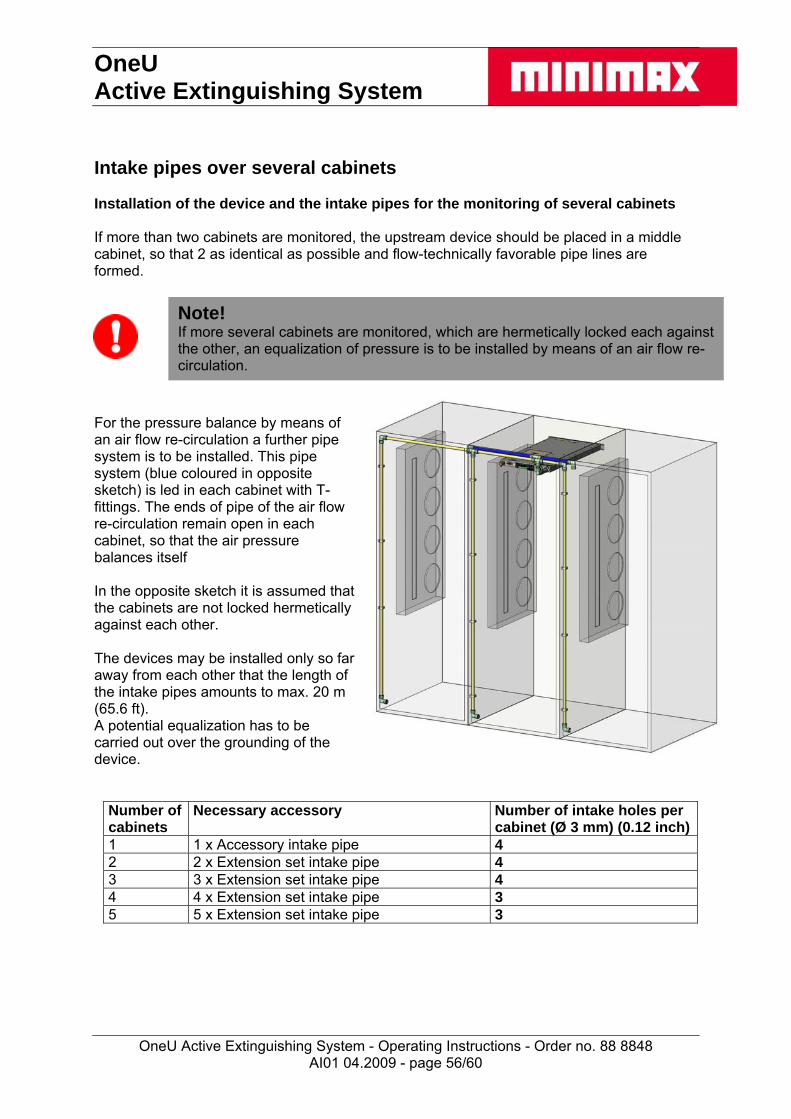
OneU Active Extinguishing System
OneU Active Extinguishing System - Operating Instructions - Order no. 88 8848
Intake pipes over several cabinets Installation of the device and the intake pipes for the monitoring of several cabinets If more than two cabinets are monitored, the upstream device should be placed in a middle cabinet, so that 2 as identical as possible and flow-technically favorable pipe lines are formed.
Note! If more several cabinets are monitored, which are hermetically locked each against the other, an equalization of pressure is to be installed by means of an air flow re-circulation.
For the pressure balance by means of an air flow re-circulation a further pipe system is to be installed. This pipe system (blue coloured in opposite sketch) is led in each cabinet with T-fittings. The ends of pipe of the air flow re-circulation remain open in each cabinet, so that the air pressure balances itself In the opposite sketch it is assumed that the cabinets are not locked hermetically against each other. The devices may be installed only so far away from each other that the length of the intake pipes amounts to max. 20 m (65.6 ft). A potential equalization has to be carried out over the grounding of the device.
Number of cabinets
Necessary accessory Number of intake holes per cabinet (Ø 3 mm) (0.12 inch)
1 1 x Accessory intake pipe 4 2 2 x Extension set intake pipe 4 3 3 x Extension set intake pipe 4 4 4 x Extension set intake pipe 3 5 5 x Extension set intake pipe 3
AI01 04.2009 - page 56/60
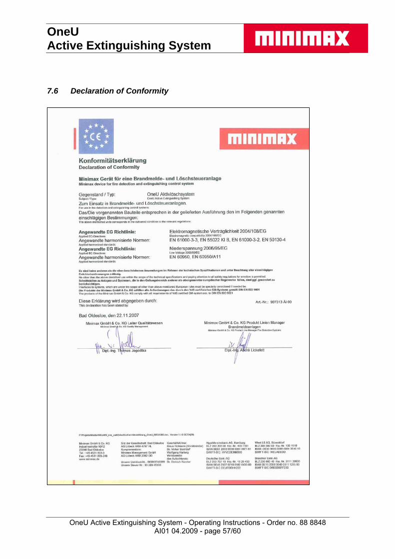
OneU Active Extinguishing System
OneU Active Extinguishing System - Operating Instructions - Order no. 88 8848
7.6 Declaration of Conformity
AI01 04.2009 - page 57/60

OneU Active Extinguishing System
OneU Active Extinguishing System - Operating Instructions - Order no. 88 8848
AI01 04.2009 - page 58/60
Notes
OneU Active Extinguishing System
OneU Active Extinguishing System - Operating Instructions - Order no. 88 8848
AI01 04.2009 - page 59/60

OneU Active Extinguishing System
OneU Active Extinguishing System - Operating Instructions - Order no. 88 8848
AI01 04.2009 - page 60/60
Empty dummy page