Embed Size (px)
Citation preview

U.P.B. Sci. Bull., Series B, Vol. 79, Iss. 4, 2017 ISSN 1454-2331
ONE SIDE POLYANILINE COATED FIBERS BASED
ACTUATOR
Mihaela BEREGOI1, Alexadru EVANGHELIDIS2, Paul GANEA3,
Horia IOVU4, Elena MATEI5, Ionut ENCULESCU6
In this study, one side aligned PANI coated micro-fibers were fabricated in
order to develop a novel actuator configuration. Thus, electrospun PMMA fibers
were coated only on one side with a thin gold layer guiding in this way the
deposition of PANI (only on the side with gold considering an adequate PANI
deposition time). Further, the half-metalized fibers were employed as working
microelectrodes for electrochemical deposition of PANI. The prepared PANI coated
fibers present actuation properties when they are in contact with an electrolyte like
1 M H2SO4. By switching the potential between +1.4 and -0.2 V, the fiber strips
move due to the swelling/shrinking and anisotropic deposition of PANI film.
Keywords: polyaniline, fibers, actuator, artificial muscles, electrospinning,
impedance measurements
1. Introduction
The interest in fabricating actuating micro-devices has been increasing in
the past years as a consequence of high demand of biomimetic complex
mechanisms such as tissue substitutes, implantable neuronal devices, animal-like
robots, etc. [1-3]. In this context, conducting polymers (CP) are suitable
candidates for such applications considering their biocompatibility, low actuation
potentials and high mechanical properties [4,5]. The electroactivity of CP can be
attributed to the doping/un-doping processes which occur when these materials
are in contact with an ions source. Once the ions are moving inside and outside of
1 PhD Student, Dept. of Bioresources and Polymer Science, Faculty of Applied Chemistry and
Materials Science, University POLITEHNICA of Bucharest; Researcher Assistant at National
Institute of Materials Physics, Magurele, Ilfov, Romania, e-mail: [email protected] 2 PhD Student, Faculty of Physics, University of Bucharest; Researcher Assistant at National
Institute of Materials Physics, Magurele, Ilfov, Romania, e-mail: [email protected] 3 PhD, National Institute of Materials Physics, Magurele, Ilfov, Romania, e-mail:
[email protected] 4 Prof., Dept. of Bioresources and Polymer Science, Faculty of Applied Chemistry and Materials
Science, University POLITEHNICA of Bucharest, Romania, e-mail: [email protected] 5 PhD, National Institute of Materials Physics, Magurele, Ilfov, Romania, e-mail:
[email protected] 6 PhD, National Institute of Materials Physics, Magurele, Ilfov, Romania, e-mail: [email protected],
* corresponding author: [email protected]
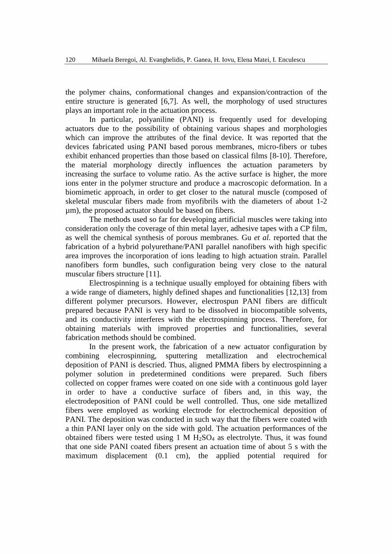
120 Mihaela Beregoi, Al. Evanghelidis, P. Ganea, H. Iovu, Elena Matei, I. Enculescu
the polymer chains, conformational changes and expansion/contraction of the
entire structure is generated [6,7]. As well, the morphology of used structures
plays an important role in the actuation process.
In particular, polyaniline (PANI) is frequently used for developing
actuators due to the possibility of obtaining various shapes and morphologies
which can improve the attributes of the final device. It was reported that the
devices fabricated using PANI based porous membranes, micro-fibers or tubes
exhibit enhanced properties than those based on classical films [8-10]. Therefore,
the material morphology directly influences the actuation parameters by
increasing the surface to volume ratio. As the active surface is higher, the more
ions enter in the polymer structure and produce a macroscopic deformation. In a
biomimetic approach, in order to get closer to the natural muscle (composed of
skeletal muscular fibers made from myofibrils with the diameters of about 1-2
µm), the proposed actuator should be based on fibers.
The methods used so far for developing artificial muscles were taking into
consideration only the coverage of thin metal layer, adhesive tapes with a CP film,
as well the chemical synthesis of porous membranes. Gu et al. reported that the
fabrication of a hybrid polyurethane/PANI parallel nanofibers with high specific
area improves the incorporation of ions leading to high actuation strain. Parallel
nanofibers form bundles, such configuration being very close to the natural
muscular fibers structure [11].
Electrospinning is a technique usually employed for obtaining fibers with
a wide range of diameters, highly defined shapes and functionalities [12,13] from
different polymer precursors. However, electrospun PANI fibers are difficult
prepared because PANI is very hard to be dissolved in biocompatible solvents,
and its conductivity interferes with the electrospinning process. Therefore, for
obtaining materials with improved properties and functionalities, several
fabrication methods should be combined.
In the present work, the fabrication of a new actuator configuration by
combining elecrospinning, sputtering metallization and electrochemical
deposition of PANI is descried. Thus, aligned PMMA fibers by electrospinning a
polymer solution in predetermined conditions were prepared. Such fibers
collected on copper frames were coated on one side with a continuous gold layer
in order to have a conductive surface of fibers and, in this way, the
electrodeposition of PANI could be well controlled. Thus, one side metallized
fibers were employed as working electrode for electrochemical deposition of
PANI. The deposition was conducted in such way that the fibers were coated with
a thin PANI layer only on the side with gold. The actuation performances of the
obtained fibers were tested using 1 M H2SO4 as electrolyte. Thus, it was found
that one side PANI coated fibers present an actuation time of about 5 s with the
maximum displacement (0.1 cm), the applied potential required for

One side polyaniline coated fibers based actuator 121
contraction/expansion are -0.2 and +1.4 V. Comparing with PANI completely
covered fibers which show no movement due to the symmetrical volume changes,
in this case, the asymmetric PANI film induces a displacement of the entire fiber
strip.
2. Experimental
2.1. Materials
PMMA (MW=350.000 g/mol) and N, N-dimethylformamide (≥ 99.8 %)
were purchased from Sigma Aldrich. The precursors for synthesizing PANI,
aniline (99+ %, Alfa Aesar) and sulfuric acid (95-97 %, Sigma Aldrich) were used
without further purifications. All solutions were prepared using Millipore
distillated water.
2.2. One side coated PANI fibers fabrication
Aligned electrospun PMMA fibers were prepared by using an in-house
electrospinning setup equipped with an aluminum rotating drum collector with
copper frames attached on it. The drum collector was rotated with a speed of
about 2000 rpm. The spinneret consisted in a syringe needle through the polymer
solution was fed with a rate of 0.5 ml/h by applying 20 kV. The precursor solution
consisted in 10% (w/v) PMMA in N, N-dimethylformamide, and the collecting
time was about 30 min.
Aligned PMMA fibers attached on copper frames were coated on one side
with a gold layer by using DC magnetron sputtering. The metallized fibers were
transferred on stainless steel frames in order to electrochemically deposit PANI.
The polymerization procedure involves the use of the one side coated metallized
fibers as working electrode, a platinum plate as counter electrode and a saturated
calomel electrode (SCE) as reference. The precursor mixture was an aqueous
solution composed of 0.05 M aniline and 1 M H2SO4. Consecutive
chronoampetrometric pulses (with 0 V the lower limit and 1 V as upper limit),
with a delay time of 0.5 s were applied in order to fabricate PANI thin layers. The
deposition time was 65 s which was chosen in order to obtain the optimal PANI
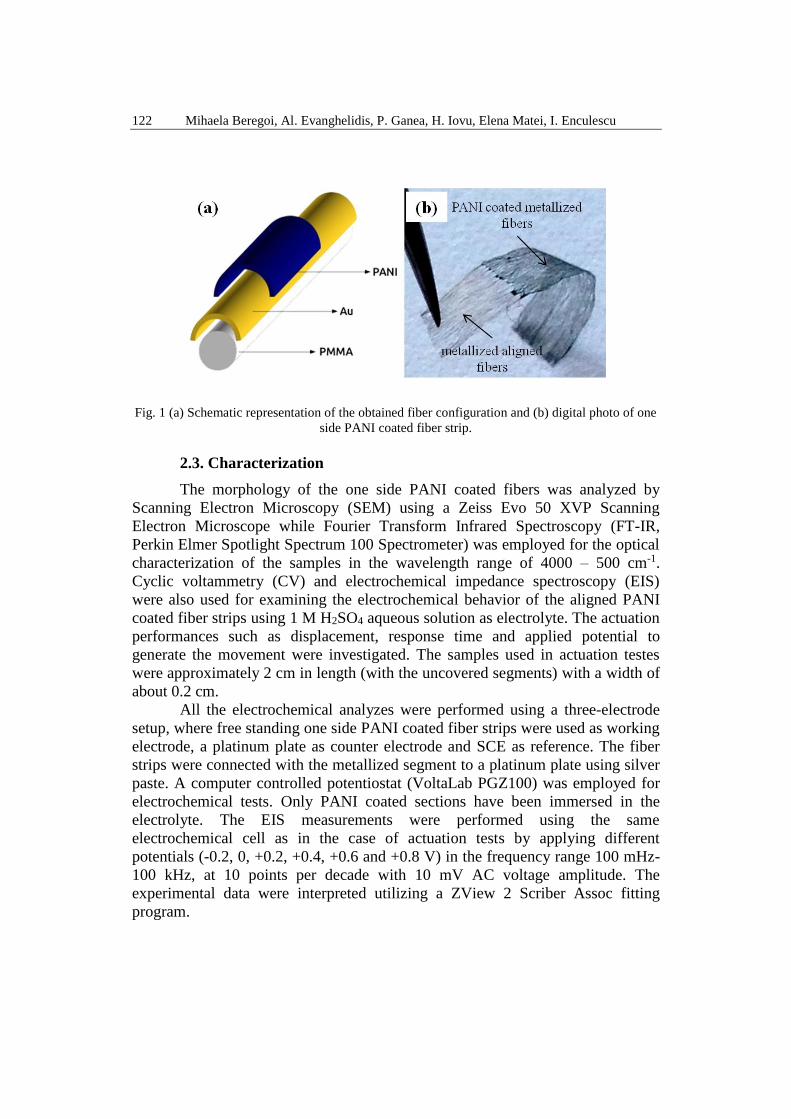
layer deposited on the gold covered side. The configuration of the resulting PANI
coated fibers is presented in Fig. 1(a). Fig. 1(b) shows the digital photo of the
fiber strip coated with PANI with an uncovered segment which serves as contact.
122 Mihaela Beregoi, Al. Evanghelidis, P. Ganea, H. Iovu, Elena Matei, I. Enculescu
Fig. 1 (a) Schematic representation of the obtained fiber configuration and (b) digital photo of one
side PANI coated fiber strip.
2.3. Characterization
The morphology of the one side PANI coated fibers was analyzed by
Scanning Electron Microscopy (SEM) using a Zeiss Evo 50 XVP Scanning
Electron Microscope while Fourier Transform Infrared Spectroscopy (FT-IR,
Perkin Elmer Spotlight Spectrum 100 Spectrometer) was employed for the optical
characterization of the samples in the wavelength range of 4000 – 500 cm-1.
Cyclic voltammetry (CV) and electrochemical impedance spectroscopy (EIS)
were also used for examining the electrochemical behavior of the aligned PANI
coated fiber strips using 1 M H2SO4 aqueous solution as electrolyte. The actuation
performances such as displacement, response time and applied potential to
generate the movement were investigated. The samples used in actuation testes
were approximately 2 cm in length (with the uncovered segments) with a width of
about 0.2 cm.
All the electrochemical analyzes were performed using a three-electrode
setup, where free standing one side PANI coated fiber strips were used as working
electrode, a platinum plate as counter electrode and SCE as reference. The fiber
strips were connected with the metallized segment to a platinum plate using silver
paste. A computer controlled potentiostat (VoltaLab PGZ100) was employed for
electrochemical tests. Only PANI coated sections have been immersed in the
electrolyte. The EIS measurements were performed using the same
electrochemical cell as in the case of actuation tests by applying different
potentials (-0.2, 0, +0.2, +0.4, +0.6 and +0.8 V) in the frequency range 100 mHz-
100 kHz, at 10 points per decade with 10 mV AC voltage amplitude. The
experimental data were interpreted utilizing a ZView 2 Scriber Assoc fitting
program.

One side polyaniline coated fibers based actuator 123
3. Results and discussions
3.1. Morphological characterization
The fabrication of one side PANI coated fibers involves the combination
of several preparation methods, hence the resulting fibres morphology was
analyzed after each step.
Thus, in Fig. 3(a, a') and 3(b, b') the SEM images of one side metallized
PMMA fibers and PANI coated fibers (with a deposition time of 65 s) are
presented. As it can be noticed, the gold layer is smooth, continous along PMMA
fibers and have a thickness of about 100 nm. Compared with the gold layer, the
PANI film presents some bumps, it is uniform deposited along the fibers and
reaches an approximate thickness of 300 nm. The PANI deposition time was short
enough in order to deposit PANI only on the fibers, avoiding the formation of a
thick PANI embadded fibers film . Likewise, the fibers are well aligned, their
diameter after PANI deposition hovering between 1 - 2 µm. The covering of the
fibers only on one side was noticed by dissolving the PMMA cores in
dichloromethane, and in the end some half microtubes were obtained.
Fig. 2 SEM images of (a, a') the aligned gold coated PMMA fibers and (b, b') PANI covered
metalized ones.
124 Mihaela Beregoi, Al. Evanghelidis, P. Ganea, H. Iovu, Elena Matei, I. Enculescu
3.2. Structural analysis
After the PANI deposition process, the samples were rinsed with Millipore
water and dried. Thus, FTIR spectrum of one side PANI coated fibers was
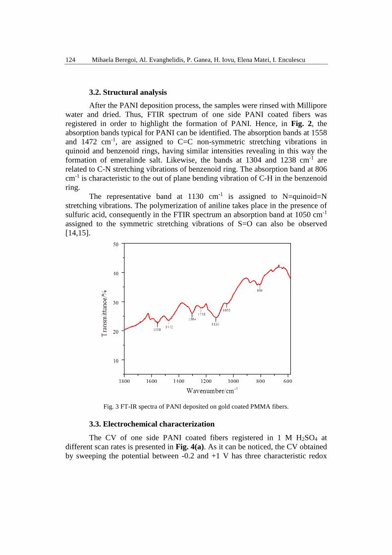
registered in order to highlight the formation of PANI. Hence, in Fig. 2, the
absorption bands typical for PANI can be identified. The absorption bands at 1558
and 1472 cm-1, are assigned to C=C non-symmetric stretching vibrations in
quinoid and benzenoid rings, having similar intensities revealing in this way the
formation of emeralinde salt. Likewise, the bands at 1304 and 1238 cm-1 are
related to C-N stretching vibrations of benzenoid ring. The absorption band at 806
cm-1 is characteristic to the out of plane bending vibration of C-H in the benzenoid
ring.
The representative band at 1130 cm-1 is assigned to N=quinoid=N
stretching vibrations. The polymerization of aniline takes place in the presence of
sulfuric acid, consequently in the FTIR spectrum an absorption band at 1050 cm-1
assigned to the symmetric stretching vibrations of S=O can also be observed
[14,15].
Fig. 3 FT-IR spectra of PANI deposited on gold coated PMMA fibers.
3.3. Electrochemical characterization
The CV of one side PANI coated fibers registered in 1 M H2SO4 at
different scan rates is presented in Fig. 4(a). As it can be noticed, the CV obtained
by sweeping the potential between -0.2 and +1 V has three characteristic redox

One side polyaniline coated fibers based actuator 125
pairs of peaks. According to the literature, the first pair of peaks appears (+0.2 and
+0.1 V) due to the transition of leucoemeraldine to emeraldine salt, and second
one (+0.6 and +0.8 V) is assigned the transition of emeraldine salt to
pernigraniline. The third pair of peak (+0.5 and +0.55 V) could be associated with
the formation of a PANI crosslinked structure or its partial degradation [16,17].
By increasing the scan rate, the cathodic and anodic peaks present slight shifts to
more electropositive potentials and more electronegative potentials, this being a
consequence of slow electron transfer processes in quasi or irreversible systems
[18]. Fig. 4(b) shows the relation between the peak current (I) and scan rate (v) up
to 250 mV/s, for the oxidation and reduction process. The obtained linear relation
(the slope of PANI oxidation is 0.89379 ± 0.01893, and for reduction 0.69832 ±
0.03855) reveals that the oxidation/reduction is governed by combined adsorption
and diffusion processes.
Fig. 4 (a) CV of PANI coated fibers at different scan rates, registered in 1 M H2SO4 and (b) the
dependency of absolute values of peak currents on scan rate, R2 is the correlation coefficient.
Further, for a better understanding of the actuation mechanism of one side
PANI coated fiber meshes, impedance spectra using 1 M H2SO4 as ion source
were recorded, by applying different potential for reducing and oxidizing PANI
layer. The obtained results were analyzed considering a Randles electrical
equivalent circuit consisting of an electrolyte resistance, a charge transfer
resistance, one constant phase element which corresponds to the double layer
capacitance of a rugged electrode and a Warburg element attributed to the
diffusion processes.
Thus, in Fig. 5a-f the Nyquist plots (imaginary part, Z'' vs. real part, Z') are
presented, both the experimental and fitted data. All the representations as a
function of applied potential include a straight line in the low frequency range,
followed by a semicircle which appears in the high frequency domain. The large
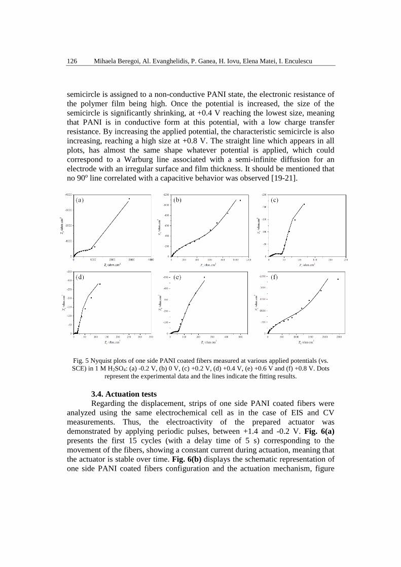
126 Mihaela Beregoi, Al. Evanghelidis, P. Ganea, H. Iovu, Elena Matei, I. Enculescu
semicircle is assigned to a non-conductive PANI state, the electronic resistance of
the polymer film being high. Once the potential is increased, the size of the
semicircle is significantly shrinking, at +0.4 V reaching the lowest size, meaning
that PANI is in conductive form at this potential, with a low charge transfer
resistance. By increasing the applied potential, the characteristic semicircle is also
increasing, reaching a high size at +0.8 V. The straight line which appears in all
plots, has almost the same shape whatever potential is applied, which could
correspond to a Warburg line associated with a semi-infinite diffusion for an
electrode with an irregular surface and film thickness. It should be mentioned that
no 90o line correlated with a capacitive behavior was observed [19-21].
Fig. 5 Nyquist plots of one side PANI coated fibers measured at various applied potentials (vs.
SCE) in 1 M H2SO4: (a) -0.2 V, (b) 0 V, (c) +0.2 V, (d) +0.4 V, (e) +0.6 V and (f) +0.8 V. Dots
represent the experimental data and the lines indicate the fitting results.
3.4. Actuation tests
Regarding the displacement, strips of one side PANI coated fibers were
analyzed using the same electrochemical cell as in the case of EIS and CV
measurements. Thus, the electroactivity of the prepared actuator was
demonstrated by applying periodic pulses, between +1.4 and -0.2 V. Fig. 6(a)
presents the first 15 cycles (with a delay time of 5 s) corresponding to the
movement of the fibers, showing a constant current during actuation, meaning that
the actuator is stable over time. Fig. 6(b) displays the schematic representation of
one side PANI coated fibers configuration and the actuation mechanism, figure

One side polyaniline coated fibers based actuator 127
which is correlated with Fig. 6(c, d, e) in which digital photos of the fibers when
the potential is switched between +1.4 and -0.2 V are presented. The fibers
contract until reaching a final point and return to the initial position when the
potential is switched to +1.4 V. The mechanism that describes the movement of
PANI coated fibers is based on the migration of the electrolyte ions in/out of
PANI film causing the swelling and shrinking of the electroactive layer, inducing
the movement of the entire fiber [22,23]. Likewise, the deposition of the
electroactive film only on one side has an important role in the fibers movement
process because a full PANI coverage would be unable to promote a displacement
due to the symmetric volume changes that occur during ions migration. Moreover,
the distribution of the gold layer along the fibers provides a uniform propagation
of the applied potential, making possible the movement of the fiber tips. In this
case, the response time is in the range of few seconds with the maximum
displacement. However, the displacement is relatively low (0.1 cm) maybe due to
the PMMA fibers which cumber the structures. Removing the PMMA cores could
enhance the displacement and decreases the actuation potential [24].
Fig. 6 (a) The first 15 cycles of one side PANI coated fibers recorded during actuation, in 1 M
H2SO4 vs. SCE; (b) Schematic representation of fibers bending; (c, d, e) snapshots taken during
actuation when the potential is switched between +1.4 V and -0.2 V.

128 Mihaela Beregoi, Al. Evanghelidis, P. Ganea, H. Iovu, Elena Matei, I. Enculescu
Further, CVs of one side PANI coated fibers before and after 30
consecutive cycles were recorded and displayed in Fig. 7(a, b). Thus, the applied
potential was switched between +1.4 and -0.2 V, the pulse width was about 5 s,
for 30 cycles, in 1 M H2SO4. It can be noticed that, after the actuation tests, the
registered CV is changed, the PANI typical pairs of peaks are decreasing in
intensity or are vanishing. Such behavior indicats a slight degradation of PANI
due to the hydrolysis reaction (because the actuation tests are performed in
aqueous solution) and due to an over-oxidation (the PANI coated fibers return to
the initial position only by applying +1.4 V).
Fig. 7 CVs of one side PANI coated fibers (a) before and (b) after 30 applied cycles, at the sweep
rate of 50 mV/s.
4. Conclusions
In the present work, a new actuator configuration based on one side PANI
coated electrospun fibers was developed and tested using 1 M H2SO4 aqueous
solution as electrolyte. The SEM images revealed a fibrous material made of well
aligned fibers uniformly coated with an electroactive polymer layer. The
deposition of gold only on one side of the fibers allows PANI to be deposited only
on that side, inducing in this way an anisotropy in the actuator configuration
which also has a contribution in the fibers bending (a complete coverage of the
fibers does not induce any movement because of the generated symmetric volume
changes).
The actuation performances of one side PANI coated fibers were
investigated by applying consecutive pulses (with the upper limit of +1.4 V and
lower limit of -0.2 V), revealing a bending motion generated by the
swelling/shrinking of the PANI layer. In these conditions, the registered

One side polyaniline coated fibers based actuator 129
displacement was of about 0.1 cm and the response time was in the range of few
seconds (with the maximum displacement).
Acknowledgment
The research was financially supported by the Core Founding Programs,
contract no. PN16-480102 and project PED 128/2017.
R E F E R E N C E S
[1] N. K. Guimard, N. Gomez and C. E. Schmidt, “Conducting polymers in biomedical
engineering”, in Prog. Polym. Sci., vol. 32, June 2007, pp. 876-921.
[2] E. Smela, “Conducting Polymer Actuators for Biomedical Applications”, in Adv. Mater., vol.
15, no. 6, March 2003, pp. 481-494.
[3] R.H. Baughman, “Conducting polymer artificial muscles”, in Synth. Met., vol. 78, November
1995, pp. 339-353.
[4] M. Beregoi, C. Busuioc, A. Evanghelidis, E. Matei, F. Iordache, M. Radu, A. Dinischiotu and
I. Enculescu, “Electrochromic properties of polyaniline-coated fiber webs for tissue
engineering applications”, in Int. J. Pharm., vol. 510, November 2015, pp. 465-473.
[5] R.Ansari and M. B. Keivani, “Polyaniline Conducting Electroactive Polymers: Thermal and
Environmental Stability Studies”, in E-Journal of Chemistry, vol. 3, no. 4, October 2006,
pp. 202-217.
[6] K. Kaneto, Conducting Polymers in Soft Actuators: Materials, Modeling, App;lications and
Fture Perspectives, Springer, Tokyo, Japan, pp. 95-109, 2014.
[7] Q.Pei, O. Inganas and l. Lundstrom, “Bending bilayer strips built from polyaniline for artificial
electrochemical muscles”, in Smart Mater. Struct, vol. 2, January 1993, pp. 1-6.
[8] B. Xi, V.-T. Truong, V. Mottaghitalab, P. G Whitten, G. M. Spinks and G. G Wallace,
“Actuation behaviour of polyaniline films and tubes prepared by the phase inversion
technique”, in Smart Mater. Struct., vol. 16, July 2007, pp. 1549–1554.
[9] B. Qi, W. Lu and B. R. Mattes, “Strain and Energy Efficiency of Polyaniline Fiber
Electrochemical Actuators in Aqueous Electrolytes”, in J. Phys. Chem. B, vol 108, No. 20,
April 2004, pp. 6222-6227.
[10] J.-M. Sansinena, J. Gao and H.-L. Wang, “High-Performance, Monolithic Polyaniline
Electrochemical Actuators”, in Adv. Funct. Mater., vol. 13, no. 9, September 2003, pp.
703-709.
[11] B. K. Gu, Y. A. Ismail, G. M. Spinks, S. I. Kim, I. So and S. J. Kim, “A Linear Actuation of
Polymeric Nanofibrous Bundle for Artificial Muscles”, Chem. Mater., vol. 21, January
2009, 511–515.
[12] N. Bhardwaj and S.C. Kundu, “Electrospinning: Afascinating fiber fabrication technique”, in
Biotechnol. Adv., vol. 28, January 2010, pp. 325–347.
[13] P. H. S. Picciani, E. S. Medeiros, W. J. Orts and L. H. C. Mattoso, Advances in Electroactive
Electrospun Nanofibers in Nanofibers – Production, Properties and Functional
Applications, In Tech, China, pp. 85-116, 2011
[14] M. Trchova and J. Stejskal, “Polyaniline: The infrared spectroscopy of conducting polymer
nanotubes (IUPAC Technical Report)”, in Pure Appl. Chem., vol. 83, no. 10, June 2011,
pp. 1803–1817.

130 Mihaela Beregoi, Al. Evanghelidis, P. Ganea, H. Iovu, Elena Matei, I. Enculescu
[15] I.A Dumitrescu, C.-A. Nicolae, A. M. Mocioiu, R. A. Gabor, M. Grigorescu, M. Mihailescu,
“Synthesis and characterization of conductive polymers with enhanced solubility”, in
U.P.B. Sci. Bull., Series A, vol. 71, no. 4, 2009, pp. 63-72.
[16] V. Tsakova and A. Milchev, “Electrochemical formation and stability of polyaniline films”, in
Electrochim. Acta, vol. 36, no. 10, January 1991, pp. 1579-1583.
[17] E. M. Genies, M. Lapkowski and J. F. Penneau, “Cyclic Voltammetry of polyaniline:
Interpretation the middle peak”, in J. Electroanal. Chem., vol. 249, April 1988, pp. 97-107.
[18] C. M. A. Brett and A. M. Brett, “Electrochemistry: Principles, Methods, and Applications”,
Oxford University Press, 1993, pp. 182.
[19] W. Lu and B. R. Mattes, “Electrochemical behavior and electromechanical actuation of PANI
in nonaqueous electrolytes”, in . Electrochem. Soc., vol. 150, no. 9, July 2003, pp. E416-
E422.
[20] P. Fiordiponti and G. Pistoia, “An impendace study of polyaniline films in aqueous and
organic solutions”, in Electrochim. Acta, vol. 34, no. 2, 1989, pp. 215-221.
[21] K.-H. Lumbert and L. Dunsch, “The influence of protons on the impedance of polynailine
films”, Electrochim. Acta, vol. 43, no. 7, 1998, pp.813-822.
[22] L. Lizarraga, E. M. Andrade and F. V. Molina, “Swelling and volume changes of polyaniline
upon redox switching”, J. Electroanal. Chem., vol. 561, 2004, pp. 127–135.
[23] E. W. H. Jager, E. Smela and O. Ingana, “Microfabricating Conjugated Polymer Actuators”,
in Science, vol. 290, November 2000, pp. 1540-1545.
[24] M. Beregoi, A. Evanghelidis, E. Matei and I. Enculescu, “Polyaniline Based Microtubes as
Building-Blocks for Artificial Muscle Applications”, in Sens. Actuator B-Chem., June
2017, https://doi.org/10.1016/j.snb.2017.06.128.