Embed Size (px)
Citation preview

MIN: 2.95 x 2.95 in / 75 x 75 mm
MAX:3.94 x 3.94 in / 100 x 100 mm
MIN:3.07 in / 78 mm
MAX:21.65 in / 550 mm
Item No: 63607068/63607107/63607139
Congratulations on your latest Atlantic purchase. Follow these simple instructions and you’ll have your TV mounted in no time.
This kit fits most TVs 37in - 84in. (94cm - 213.4cm), up to 132lbs (60kgs).
Keep this Instruction Manual for future reference.Keep your original proof of purchase (store receipt).
www.atlantic-inc.com
If you have any questions and/or wish to order parts, please call us toll free at 800-747-2660, oremail ‘[email protected]’
One Arm Articulating TV Wall Mount

37 9484 213.4

2
Item ItemComponents Components
A 1
B 1
C 2
D 2
F
G
4
8
H 1
16 in/406 mm
or
24 in/610 mm
Note:
before assembly.
Wood Double Stud
Parts List
ytQytQ
5/16 in. or 8 mm
Safety Hammer Wood Drill Bit Phillips Drill Stud Finder Glasses Screwdriver
Tools Needed (Not Included)
2 x 8.66in. (220mm) Velcro Cable Ties
3
16”/406mm
or
24”/610mm
F
A
B
AB
PLEASE CHOOSE BEST INSTALLATION OPTION BASED ON TV BACK PANEL HOLE SPACING:
OPTION 1: 2.95 in x 2.95 in / 75 mm x 75 mm or 3.94 in x 3.94 in / 100 mm x 100 mm
21
3
Remove TV mounting plate (B) from wallbracket (A).
This mount is designed to be attached into wood studs. DO NOT use wall anchors. Using a stud
pencil, mark the hole locations at the desired height, making sure you are level. Use wall bracket (A) as a template to mark the two remaining holes. Drill pilot holes at 4 pencil marks 2.5 in. (64mm) deep, using a 5/16 in. or 8 mm diameter drill bit.
Attach wall bracket (A) to the wall with 4 screws (F).
Attach TV mounting plate (B) to the back of the TV, by selecting mounting hardware and then using instructions on page 6.
We strongly recommend two people, one on each side, hold the TV. Carefully position the TV over the wall bracket (A) until it locks in place. Tighten safety screws.
4
Safety Screws

4
16”/406mm
o
r
24”/610mm
F
A
1
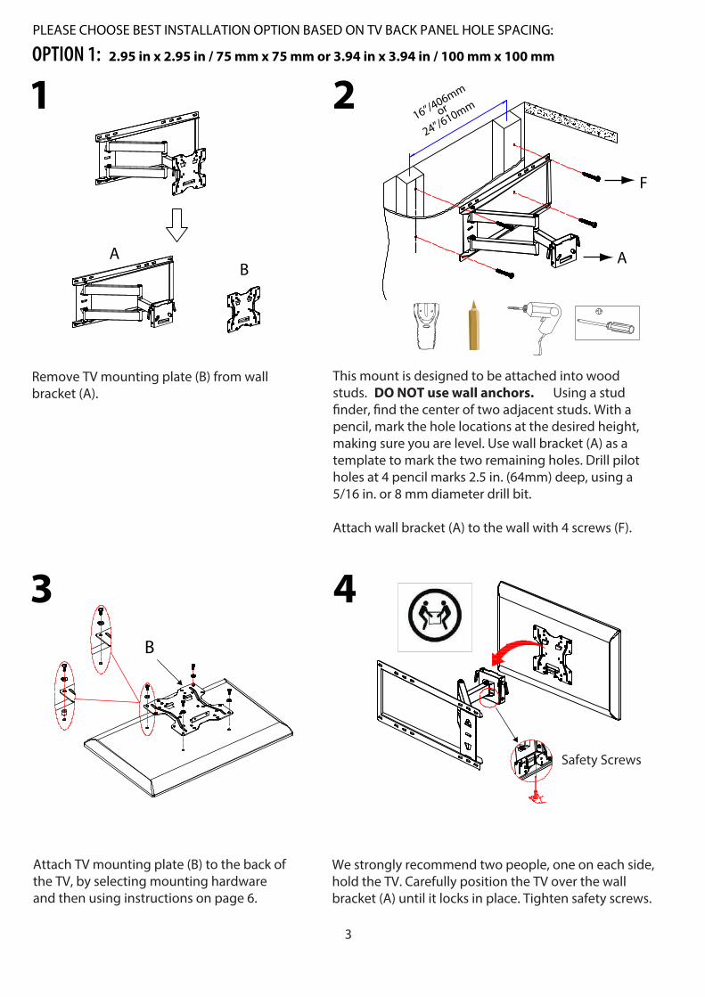
PLEASE CHOOSE BEST INSTALLATION OPTION BASED ON TV BACK PANEL HOLE SPACING:
OPTION 2: (7.87 to 23.6) in x 15.7 in / (200 to 600) mm x 400 mm
H
2
Attach horizontal bar (D) to TV mounting plate (B), then �x it with screws (G) and allen wrench (H).
D
B
D
B
G
This mount is designed to be attached into wood studs. DO NOT use wall anchors. Using a stud �nder, �nd the center of two adjacent studs. With a pecil, mark the hole locations at the desired height, making sure you are level. Use wall bracket (A) as a template to mark the two remaining holes. Drill pilot holes at 4 pencil marks 2.5 in. (64mm) deep, using a 5/16in. or 8 mm diameter drill bit.
Attach wall bracket (A) to the wall with 4 screws (F).

3C
D C
D
Figure 1
G
UP
C
D
5
Slide TV mounts (C) along with TV horizontal bar (D). See Figure 1.
allen wrench (H).Selecting mounting hardware and then using instructions on Page 6
We strongly recommend two people, one on each side, hold the TV. Carefully position the TV over the wall bracket (A) until it locks in place. Tighten safety screws.
4
Safety Screws
H

6
Mounting Hardware List Q’ty Mounting Hardware List Q’ty
M8 X 16
M6 X 12
M5 X 12
M4 X 12
M8 X 40
M6 X 35
M5 X 30
M4 X 30
4
4
4
4
4
4
4
4
M4 / M 5 washer
M6 / M 8 washer
M8 / M6 spacer
M4 / M5 spacer
4
4
4
4
I
J
K
L
M
N
O
P
Q
R
S
T
(7.87 to 23.6) in x 15.7 in(200 to 600) mm x 400 mm
2.95 in x 2.95 in / 75 mm x 75 mm 3.94 in x 3.94 in / 100 mm x 100 mm
OPTION 1 OPTION 2
TAKE EXTRA CARE AND PAY ATTENTION WHEN YOU FASTEN THE TV MOUNT(S) TO THE BACK TV PANEL IN STEP 3. MAKE SURE TO USE THE APPROPRIATE MOUNTING HARDWARE FOR YOUR TV.
1. Select the correct Mounting Hardware according to the screw hole size on your TV. Discard any remaining screws and spacers.
2. Carefully lay your TV face down on a non-abrasive surface, laying padding underneath it to protect the screen.
3. OPTION 1: Place the TV plate (B) in the appropriate position, making sure it is CENTERED on the back of TV and LEVEL.
OPTION 2: Place the right and left TV mounts in their appropriate positions, making sure they are CENTERED on the back of the TV and LEVEL with one another.
UP

7
U.S. and other foreign patents pending / Patentes de los EU A y países extranjeros en trámite / Brevets en cours pour les États-Unis et autres pays / U.S. und andere ausländische Patente sind hängig
All rights reserved / Derechos Reservados /Tous droits réservés
Made in China / Hecho en China / Fabriqué en Chine
www.atlantic-inc.com
R1.0 150812 #63607068/63607107/63607139
2015
Product Warranty: Atlantic Inc., warrants to the original purchaser that its products are free from defect in materials and workmanship. If after inspection, we �nd that the productwas defective in materials or workmanship we shall repair or replace the product at ourdiscretion. This warranty does not cover accidental damage, misuse, improper care or alteration and excludes claims for incidental or consequential loss. This limited warranty applies to product purchased in the U.S. and Canada. This warranty gives you speci�clegal rights and you may also have other rights which vary from State to Stage. This warranty duration will last one year from the date of purchase.