Embed Size (px)
Citation preview

Printed in U.S.A. 981-0173
HDKCA, HDKCB
08-04
Operator’s Manual
California
Proposition 65 WarningDiesel engine exhaust and some of its constituents are knownto the State of California to cause cancer, birth defects, andother reproductive harm.
diesel warnings
Page 1 of 1
Supplement: 981-1049Date: 09/04Insert with-
Manual Number (Date): 981-0173 (08/04) 981-0174 (08/04) 981-0540 (08/04)981-0170 (11/03) 981-0171 (11/03) 981-0526D (02/04)981-0166B (06/03) 981-0167B (06/03) 981-0535 (10/02)981-0161 (08/89) 981-0522B (07/99)
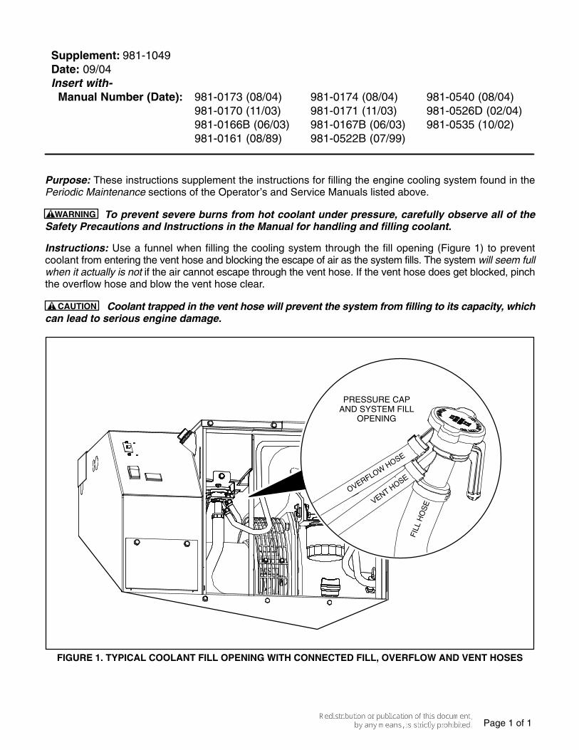
Purpose: These instructions supplement the instructions for filling the engine cooling system found in thePeriodic Maintenance sections of the Operator’s and Service Manuals listed above.
WARNING To prevent severe burns from hot coolant under pressure, carefully observe all of theSafety Precautions and Instructions in the Manual for handling and filling coolant.
Instructions: Use a funnel when filling the cooling system through the fill opening (Figure 1) to preventcoolant from entering the vent hose and blocking the escape of air as the system fills. The system will seem fullwhen it actually is not if the air cannot escape through the vent hose. If the vent hose does get blocked, pinchthe overflow hose and blow the vent hose clear.
CAUTION Coolant trapped in the vent hose will prevent the system from filling to its capacity, whichcan lead to serious engine damage.
PRESSURE CAPAND SYSTEM FILL
OPENING
FIGURE 1. TYPICAL COOLANT FILL OPENING WITH CONNECTED FILL, OVERFLOW AND VENT HOSES
i
Table of Contents
SECTION PAGE
SAFETY PRECAUTIONS iii . . . . . . . . . . . . . . . . . . . . . . . . . . . . . . . . . . . . . . . . . . . . . . . . . . . . .
1. INTRODUCTION 1-1 . . . . . . . . . . . . . . . . . . . . . . . . . . . . . . . . . . . . . . . . . . . . . . . . . . . . . . . . . .
About this Manual 1-1 . . . . . . . . . . . . . . . . . . . . . . . . . . . . . . . . . . . . . . . . . . . . . . . . . . . . .
Nameplate 1-1 . . . . . . . . . . . . . . . . . . . . . . . . . . . . . . . . . . . . . . . . . . . . . . . . . . . . . . . . . . .
How to Obtain Service 1-2 . . . . . . . . . . . . . . . . . . . . . . . . . . . . . . . . . . . . . . . . . . . . . . . . .
Emissions 1-3 . . . . . . . . . . . . . . . . . . . . . . . . . . . . . . . . . . . . . . . . . . . . . . . . . . . . . . . . . . . .
Typical Genset 1-4 . . . . . . . . . . . . . . . . . . . . . . . . . . . . . . . . . . . . . . . . . . . . . . . . . . . . . . . .
2. OPERATION 2-1 . . . . . . . . . . . . . . . . . . . . . . . . . . . . . . . . . . . . . . . . . . . . . . . . . . . . . . . . . . . . . .
Recommended Fuel 2-1 . . . . . . . . . . . . . . . . . . . . . . . . . . . . . . . . . . . . . . . . . . . . . . . . . . .
Recommended Coolant 2-1 . . . . . . . . . . . . . . . . . . . . . . . . . . . . . . . . . . . . . . . . . . . . . . . .
Recommended Engine Oil 2-1 . . . . . . . . . . . . . . . . . . . . . . . . . . . . . . . . . . . . . . . . . . . . .
Starting Batteries 2-1 . . . . . . . . . . . . . . . . . . . . . . . . . . . . . . . . . . . . . . . . . . . . . . . . . . . . .
Control Panel 2-2 . . . . . . . . . . . . . . . . . . . . . . . . . . . . . . . . . . . . . . . . . . . . . . . . . . . . . . . . .
Remote Control Panels 2-3 . . . . . . . . . . . . . . . . . . . . . . . . . . . . . . . . . . . . . . . . . . . . . . . .
Pre-Start Checks 2-4 . . . . . . . . . . . . . . . . . . . . . . . . . . . . . . . . . . . . . . . . . . . . . . . . . . . . . .
Priming the Fuel System 2-4 . . . . . . . . . . . . . . . . . . . . . . . . . . . . . . . . . . . . . . . . . . . . . . .
Manual Starting 2-4 . . . . . . . . . . . . . . . . . . . . . . . . . . . . . . . . . . . . . . . . . . . . . . . . . . . . . . .
Manual Stopping 2-4 . . . . . . . . . . . . . . . . . . . . . . . . . . . . . . . . . . . . . . . . . . . . . . . . . . . . . .
Automatic Starting and Stopping 2-5 . . . . . . . . . . . . . . . . . . . . . . . . . . . . . . . . . . . . . . . .
Loading the Genset 2-5 . . . . . . . . . . . . . . . . . . . . . . . . . . . . . . . . . . . . . . . . . . . . . . . . . . .
Resetting Circuit Breakers 2-6 . . . . . . . . . . . . . . . . . . . . . . . . . . . . . . . . . . . . . . . . . . . . . .
Connecting to Utility Power 2-6 . . . . . . . . . . . . . . . . . . . . . . . . . . . . . . . . . . . . . . . . . . . . .
Operating in Cold Weather 2-6 . . . . . . . . . . . . . . . . . . . . . . . . . . . . . . . . . . . . . . . . . . . . .
Operating in Hot Weather 2-6 . . . . . . . . . . . . . . . . . . . . . . . . . . . . . . . . . . . . . . . . . . . . . .
Operating at High Altitude 2-6 . . . . . . . . . . . . . . . . . . . . . . . . . . . . . . . . . . . . . . . . . . . . . .
Operating in Dusty Environments 2-6 . . . . . . . . . . . . . . . . . . . . . . . . . . . . . . . . . . . . . . .
Breaking In a New Engine 2-7 . . . . . . . . . . . . . . . . . . . . . . . . . . . . . . . . . . . . . . . . . . . . . .
Exercising the Genset 2-7 . . . . . . . . . . . . . . . . . . . . . . . . . . . . . . . . . . . . . . . . . . . . . . . . .
Storing the Genset 2-7 . . . . . . . . . . . . . . . . . . . . . . . . . . . . . . . . . . . . . . . . . . . . . . . . . . . .
ii
SECTION PAGE
3. PERIODIC MAINTENANCE 3-1 . . . . . . . . . . . . . . . . . . . . . . . . . . . . . . . . . . . . . . . . . . . . . . . .
General Inspection 3-2 . . . . . . . . . . . . . . . . . . . . . . . . . . . . . . . . . . . . . . . . . . . . . . . . . . . .
Checking Engine Oil Level 3-2 . . . . . . . . . . . . . . . . . . . . . . . . . . . . . . . . . . . . . . . . . . . . .
Changing Engine Oil and Oil Filter 3-3 . . . . . . . . . . . . . . . . . . . . . . . . . . . . . . . . . . . . . .
Maintaining the Battery and Battery Connections 3-4 . . . . . . . . . . . . . . . . . . . . . . . . . .
Replacing the Air Filter Element 3-4 . . . . . . . . . . . . . . . . . . . . . . . . . . . . . . . . . . . . . . . . .
Cleaning the Spark Arrestor 3-5 . . . . . . . . . . . . . . . . . . . . . . . . . . . . . . . . . . . . . . . . . . . .
Replacing the Fuel Filter 3-6 . . . . . . . . . . . . . . . . . . . . . . . . . . . . . . . . . . . . . . . . . . . . . . .
Maintaining the Coolant System 3-7 . . . . . . . . . . . . . . . . . . . . . . . . . . . . . . . . . . . . . . . .
4. TROUBLESHOOTING 4-1 . . . . . . . . . . . . . . . . . . . . . . . . . . . . . . . . . . . . . . . . . . . . . . . . . . . . .
Troubleshooting With Table 4-1 4-1 . . . . . . . . . . . . . . . . . . . . . . . . . . . . . . . . . . . . . . . . .
Fault Code Blinking 4-1 . . . . . . . . . . . . . . . . . . . . . . . . . . . . . . . . . . . . . . . . . . . . . . . . . . .
Restoring Fault Code Blinking 4-1 . . . . . . . . . . . . . . . . . . . . . . . . . . . . . . . . . . . . . . . . . .
5. SPECIFICATIONS 5-1 . . . . . . . . . . . . . . . . . . . . . . . . . . . . . . . . . . . . . . . . . . . . . . . . . . . . . . . . .
6. MAINTENANCE RECORD 6-1 . . . . . . . . . . . . . . . . . . . . . . . . . . . . . . . . . . . . . . . . . . . . . . . . .
iii
Safety Precautions
Thoroughly read the OPERATOR’S MANUALbefore operating the genset. Safe operation andtop performance can only be obtained whenequipment is operated and maintained proper-ly.
The following symbols in this manual alert you topotential hazards to the operator, service personand equipment.
DANGER alerts you to an immediate hazardthat will result in severe personal injury ordeath.
WARNING alerts you to a hazard or unsafepractice that can result in severe personal inju-ry or death.
CAUTION alerts you to a hazard or unsafepractice that can result in personal injury orequipment damage.
Electricity, fuel, exhaust, moving parts and batter-ies present hazards which can result in severe per-sonal injury or death.
GENERAL PRECAUTIONS
� Keep children away from the genset.
� Do not use evaporative starting fluids. Theyare highly explosive.
� To prevent accidental or remote starting whileworking on the genset, disconnect the nega-tive (−) battery cable at the battery.
� Let the engine cool down before removing thecoolant pressure cap or opening the coolantdrain. Hot coolant under pressure can sprayout and cause severe burns.
� Keep the genset and its compartment clean.Excess oil and oily rags can catch fire. Dirt andgear stowed in the compartment can restrictcooling air.
� Make sure all fasteners are secure andtorqued properly.
� Do not work on the genset when mentally orphysically fatigued or after consuming alcoholor drugs.
� You must be trained and experienced to makeadjustments while the genset is running—hot,moving or electrically live parts can cause se-vere personal injury or death.
� Used engine oil has been identified by someU. S. state and federal agencies as causingcancer or reproductive toxicity. Do not ingest,inhale, or contact used oil or its vapors.
� Ethylene glycol, used as engine antifreeze, istoxic to humans and animals. Clean up spillsand dispose of used engine coolant in accor-dance with local environmental regulations.
� Keep multi-class ABC fire extinguishershandy. Class A fires involve ordinary combus-tible materials such as wood and cloth; Class Bfires, combustible and flammable liquid fuelsand gaseous fuels; Class C fires, live electricalequipment. (ref. NFPA No. 10)
� Genset installation and operation must complywith all applicable local, state and federalcodes and regulations.
GENERATOR VOLTAGE IS DEADLY
� Disable the automatic genset starting featureof an inverter-charger or other automatic start-ing device before servicing the genset.
� Generator electrical output connections mustbe made by a trained and experienced electri-cian in accordance with applicable codes.
� The genset must not be connected to the pub-lic utility or any other source of electrical power.Back-feed could lead to electrocution of utilitypersonnel and damage to equipment. An ap-proved switching device must be used to pre-vent interconnections.
� Use caution when working on live electricalequipment. Remove jewelry, make sure cloth-ing and shoes are dry, stand on a dry woodenplatform or rubber insulating mat and use toolswith insulated handles.
iv
ENGINE EXHAUST IS DEADLY
� Inspect for exhaust leaks at every startup andafter every eight hours of running.
� Learn the symptoms of carbon monoxide poi-soning in the Operator’s Manual.
� Never sleep in the vehicle while the genset isrunning unless the vehicle is equipped with aworking carbon monoxide detector.
� Do not operate the genset when the vehicle isin a confined space, such as a garage.
� Disable the automatic genset starting featureof an inverter-charger or other automatic start-ing device before storing the vehicle or parkingit in a garage or other confined space.
� The exhaust system must be installed in accor-dance with the genset Installation Manual.
� Engine cooling air must not be used for heatingworking or living spaces or compartments.
DIESEL FUEL IS COMBUSTIBLE
� Do not smoke or turn electrical switches ON orOFF where fuel fumes are present or in areassharing ventilation with fuel tanks or equip-ment. Keep flames, sparks, pilot lights, arc-producing equipment and all other sources ofignition well away.
� Fuel lines must be secured, free of leaks andseparated or shielded from electrical wiring.
BATTERY GAS IS EXPLOSIVE
� Wear safety glasses.
� Do not smoke.
� To reduce arcing when disconnecting or recon-necting battery cables, always disconnect thenegative (−) battery cable first and reconnectit last.
MOVING PARTS CAN CAUSE SEVEREPERSONAL INJURY OR DEATH
� Disable the automatic genset starting featureof an inverter-charger or other automatic start-ing device before servicing the genset.
� Do not wear loose clothing or jewelry nearmoving parts such as PTO shafts, fans, beltsand pulleys.
� Keep hands away from moving parts.
� Keep guards in place over fans, belts, pulleys,and other moving parts.
FLAMMABLE VAPOR CAN CAUSE ADIESEL ENGINE TO OVERSPEED
Flammable vapor can cause a diesel engine tooverspeed and become difficult to stop, resulting inpossible fire, explosion, severe personal injury anddeath. Do not operate a diesel-powered gensetwhere a flammable vapor environment can becreated by fuel spill, leak, etc. The owners andoperators of the genset are solely responsible foroperating the genset safely.
Mobile-8
1-1
1. Introduction
ABOUT THIS MANUAL
This is the Operator’s Manual for the generator sets(gensets) listed on the front cover. Read and care-fully observe all of the instructions and precautionsin this manual. Keep this manual and the gensetInstallation Manual with the other vehicle manuals.
Operation, Periodic Maintenance and Trouble-shooting provide the instructions necessary for op-erating the genset and maintaining top perfor-mance. The owner is responsible for performingmaintenance in accordance with the PERIODICMAINTENANCE SCHEDULE (p. 3-1).
WARNING This genset is not a life support sys-tem. It can stop without warning. Children, per-sons with physical or mental limitations, andpets could suffer personal injury or death. A per-sonal attendant, redundant power or alarm sys-tem must be used if genset operation is critical.
WARNING Improper service or replacement ofparts can lead to severe personal injury or deathand to damage to equipment and property. Ser-vice personnel must be qualified to performelectrical and mechanical service.
Unauthorized modifications or replacement offuel, exhaust, air intake or speed control systemcomponents that affect engine emissions areprohibited by law in the State of California.
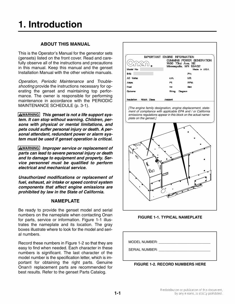
NAMEPLATE
Be ready to provide the genset model and serialnumbers on the nameplate when contacting Onanfor parts, service or information. Figure 1-1 illus-trates the nameplate and its location. The grayboxes illustrate where to look for the model and seri-al numbers.
Record these numbers in Figure 1-2 so that they areeasy to find when needed. Each character in thesenumbers is significant. The last character of themodel number is the specification letter, which is im-portant for obtaining the right parts. GenuineOnan replacement parts are recommended forbest results. Refer to the genset Parts Catalog.
[The engine family designation, engine displacement, state-ment of compliance with applicable EPA and / or Californiaemissions regulations appear in this block on the actual name-plate on the genset.]
FIGURE 1-1. TYPICAL NAMEPLATE
MODEL NUMBER: ___________________________
SERIAL NUMBER: ___________________________
FIGURE 1-2. RECORD NUMBERS HERE
1-2
HOW TO OBTAIN SERVICE
When you call for service, parts, or product literature(such as the Service Manual or Parts Catalog) foryour genset, contact the nearest authorized distrib-utor. Onan has factory-trained representatives tohandle your requests for genset parts and service.
In North America
Call 1-800-888-ONAN to contact the nearest Cum-mins/Onan or Onan-only distributor in the UnitedStates or Canada. (This automated service utilizestouch-tone phones only). Select OPTION 1(press 1) to be automatically connected to the dis-tributor nearest to you.
If you are unable to contact a distributor using theautomated service, consult the Yellow Pages. Typi-cally, our distributors are listed under:
GENERATORS − ELECTRIC,ENGINES − GASOLINE OR DIESEL, or
RECREATIONAL VEHICLES − EQUIPMENT,PARTS AND SERVICE.
If you have difficulty in arranging service or resolv-ing a problem, please contact the Service Managerat the nearest Cummins/Onan distributor for assis-tance.
Outside North America
If you are outside North America, call Onan Corpo-ration at 1−763−574−5000 from 7:30 AM to4:00 PM, Central Standard Time, Monday throughFriday, or fax 1−763−528−7229.
Information to Have Ready
Before calling for service, have the following infor-mation available:
1. The complete genset model number and serialnumber. See About This Manual (Page 1-1).
2. The date of purchase
3. The nature of the problem. See Section 4. Trou-bleshooting.
1-3
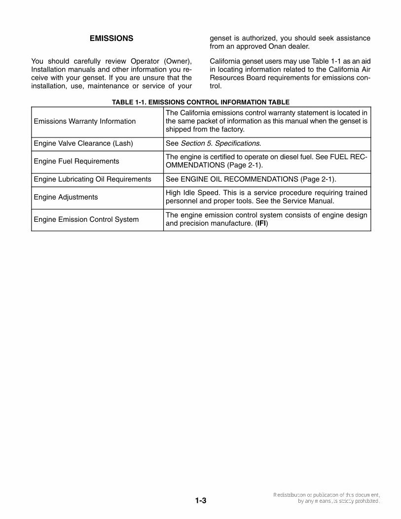
EMISSIONS
You should carefully review Operator (Owner),Installation manuals and other information you re-ceive with your genset. If you are unsure that theinstallation, use, maintenance or service of your
genset is authorized, you should seek assistancefrom an approved Onan dealer.
California genset users may use Table 1-1 as an aidin locating information related to the California AirResources Board requirements for emissions con-trol.
TABLE 1-1. EMISSIONS CONTROL INFORMATION TABLE
Emissions Warranty InformationThe California emissions control warranty statement is located inthe same packet of information as this manual when the genset isshipped from the factory.
Engine Valve Clearance (Lash) See Section 5. Specifications.
Engine Fuel RequirementsThe engine is certified to operate on diesel fuel. See FUEL REC-OMMENDATIONS (Page 2-1).
Engine Lubricating Oil Requirements See ENGINE OIL RECOMMENDATIONS (Page 2-1).
Engine AdjustmentsHigh Idle Speed. This is a service procedure requiring trainedpersonnel and proper tools. See the Service Manual.
Engine Emission Control SystemThe engine emission control system consists of engine designand precision manufacture. (IFI)

1-4
TYPICAL GENSET
Figure 1-3 illustrates the fuel, battery, remote con-trol and AC output connection points, the flow of
cooling and ventilating air and the maintenance andservice access panels of a typical genset. Notshown are the combustion air inlet and oil drainopenings in the base.
COOLING & VENTILATING AIR IN HOT AIR OUT
EXHAUSTCONNECTIONS
CONTROLPANEL
FUELCONNECTIONS
BATTERYCONNECTIONS
MAINTENANCEACCESS
AC OUTPUT AND REMOTECONTROL CONNECTIONS
FIGURE 1-3. TYPICAL GENSET
2-1
2. Operation
RECOMMENDED FUEL
WARNING Diesel fuel is combustible and cancause severe personal injury or death. Do notsmoke near fuel tanks or fuel-burning equip-ment or in areas sharing ventilation with suchequipment. Keep flames, sparks, pilot flames,electrical arcs and switches and all othersources of ignition well away. Keep a multi-class ABC fire extinguisher handy.
Use clean, fresh No. 2 diesel fuel (ASTM 2-D) whenthe outdoor ambient temperature is above freezing,and No. 1 diesel fuel (ASTM 1-D) when below freez-ing. The fuel should have a Cetane number of atleast 45 for reliable starting.
RECOMMENDED COOLANT
Use the best quality ethylene glycol antifreeze solu-tion available. It should be fully formulated with rustinhibitors and coolant stabilizers. Use fresh waterthat is low in minerals and corrosive chemicals. Dis-tilled water is best.
See for Section 5. Specifications coolant capacity.
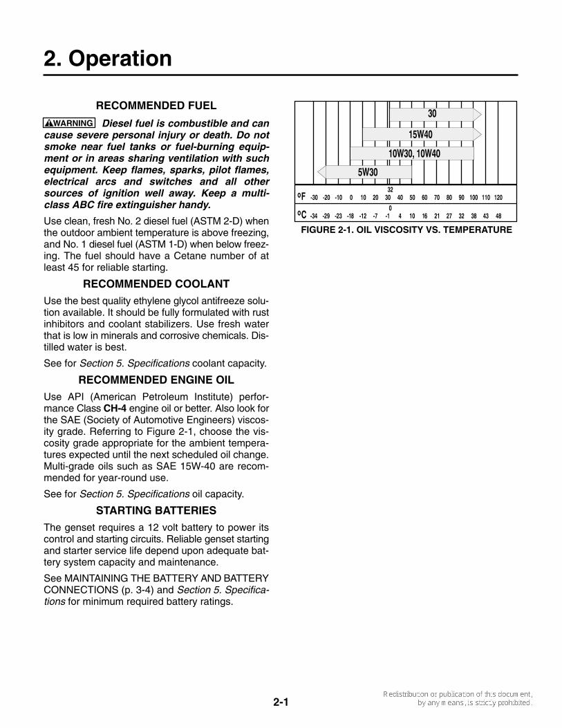
RECOMMENDED ENGINE OIL
Use API (American Petroleum Institute) perfor-mance Class CH-4 engine oil or better. Also look forthe SAE (Society of Automotive Engineers) viscos-ity grade. Referring to Figure 2-1, choose the vis-cosity grade appropriate for the ambient tempera-tures expected until the next scheduled oil change.Multi-grade oils such as SAE 15W-40 are recom-mended for year-round use.
See for Section 5. Specifications oil capacity.
STARTING BATTERIES
The genset requires a 12 volt battery to power itscontrol and starting circuits. Reliable genset startingand starter service life depend upon adequate bat-tery system capacity and maintenance.
See MAINTAINING THE BATTERY AND BATTERYCONNECTIONS (p. 3-4) and Section 5. Specifica-tions for minimum required battery ratings.
FIGURE 2-1. OIL VISCOSITY VS. TEMPERATURE
2-2
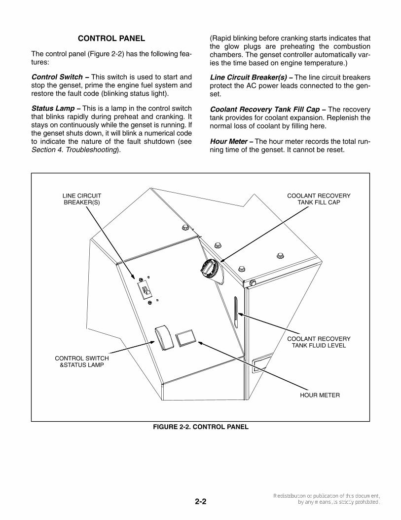
CONTROL PANEL
The control panel (Figure 2-2) has the following fea-tures:
Control Switch − This switch is used to start andstop the genset, prime the engine fuel system andrestore the fault code (blinking status light).
Status Lamp − This is a lamp in the control switchthat blinks rapidly during preheat and cranking. Itstays on continuously while the genset is running. Ifthe genset shuts down, it will blink a numerical codeto indicate the nature of the fault shutdown (seeSection 4. Troubleshooting).
(Rapid blinking before cranking starts indicates thatthe glow plugs are preheating the combustionchambers. The genset controller automatically var-ies the time based on engine temperature.)
Line Circuit Breaker(s) − The line circuit breakersprotect the AC power leads connected to the gen-set.
Coolant Recovery Tank Fill Cap − The recoverytank provides for coolant expansion. Replenish thenormal loss of coolant by filling here.
Hour Meter − The hour meter records the total run-ning time of the genset. It cannot be reset.
LINE CIRCUITBREAKER(S)
HOUR METER
CONTROL SWITCH&STATUS LAMP
COOLANT RECOVERYTANK FILL CAP
COOLANT RECOVERYTANK FLUID LEVEL
FIGURE 2-2. CONTROL PANEL
2-3
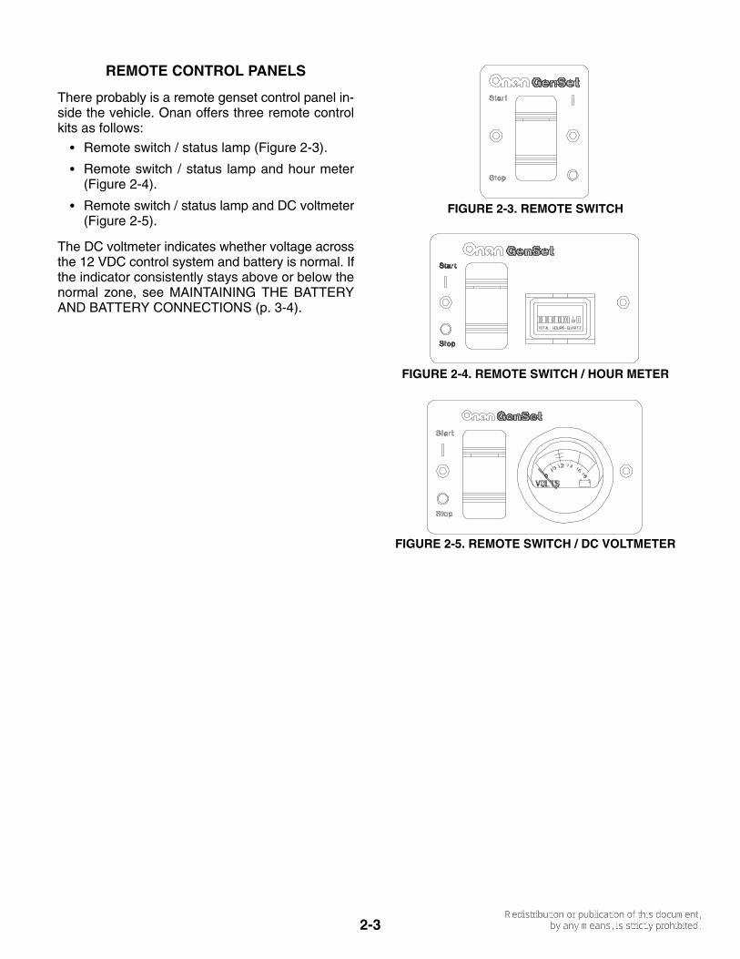
REMOTE CONTROL PANELS
There probably is a remote genset control panel in-side the vehicle. Onan offers three remote controlkits as follows:
� Remote switch / status lamp (Figure 2-3).
� Remote switch / status lamp and hour meter(Figure 2-4).
� Remote switch / status lamp and DC voltmeter(Figure 2-5).
The DC voltmeter indicates whether voltage acrossthe 12 VDC control system and battery is normal. Ifthe indicator consistently stays above or below thenormal zone, see MAINTAINING THE BATTERYAND BATTERY CONNECTIONS (p. 3-4).
FIGURE 2-3. REMOTE SWITCH
FIGURE 2-4. REMOTE SWITCH / HOUR METER
FIGURE 2-5. REMOTE SWITCH / DC VOLTMETER
2-4
WARNING EXHAUST GAS is deadly. All en-gine exhaust contains carbon monoxide; anodorless, colorless, poisonous gas that cancause unconsciousness and death. Symptomsof carbon monoxide poisoning include:
• Dizziness • Headache • Nausea • Weakness and Sleepiness• Vomiting • Inability to Think Coherently
IF YOU EXPERIENCE ANY OF THESE SYMP-TOMS, GET INTO FRESH AIR IMMEDIATELY. Ifsymptoms persist, seek medical attention. Shutdown the genset and do not operate it until it hasbeen inspected and repaired.
Never sleep in the vehicle while the genset isrunning unless the vehicle has a working car-bon monoxide detector. The exhaust systemmust be installed in accordance with the gensetInstallation Manual. Make sure there is amplefresh air when operating the genset in a con-fined area.
PRE-START CHECKS
Before the first start of the day and after every eighthours of operation, inspect the genset as instructedunder GENERAL INSPECTION (p. 3-2). Keep a logof maintenance and the hours run and perform anymaintenance that may be due. See Returning theGenset to Service (p. 2-7) if the vehicle has been instorage.
Before each start:
1. Make sure all vehicle carbon monoxide (CO)detectors are working.
2. Check for signs of fuel and exhaust leaks anddamage to the exhaust system.
3. To prevent overheating and to reduce foulingwith dust and debris, make sure the genset’snormal ground clearance is not being reducedby sloping ground, curbs, logs or other objects.Repark the vehicle if necessary and/or removeany objects blocking the air inlet or air outlet.
4. Turn off air conditioners and other large ap-pliances.
PRIMING THE FUEL SYSTEM
The fuel system should be primed after replacingthe fuel filter or running the genset out of fuel. Toprime the fuel system, hold the control switch downin its Stop position for half a minute.
MANUAL STARTING
The genset can be started and stopped from thegenset control panel or from a remote panel.
1. Perform the PRE-START CHECKS, prime thefuel system if necessary, and turn off the airconditioners and other large electrical loads.
2. Push and hold Start until the genset starts. Thestatus lamp will come on when the genset startsand will stay on while it runs. While starting it willblink rapidly indicating preheating and crank-ing. (Depending on how cold it is, preheatingcan take up to 15 seconds, extending the timethat the lamp blinks.)
CAUTION Excessive cranking can over-heat and damage the starter motor. Do notcrank for more than 30 seconds at a time.Wait at least 2 minutes before trying again.
3. See Section 4. Troubleshooting if the gensetdoes not start after several tries.
4. Let the genset warm up a few minutes until it isrunning smoothly before connecting the ve-hicle electrical loads (appliances).
5. Check for fuel, exhaust and coolant leaks. Stopthe genset immediately if there is a fuel, ex-haust or coolant leak and have it repaired.
MANUAL STOPPING
Run the genset under no load for a few minutes toallow the engine to cool down and then push and re-lease Stop.
2-5
AUTOMATIC STARTING AND STOPPING
The vehicle may be equipped with an inverter-char-ger or other automatic genset starting device. Al-ways follow the instructions and safety precautionsprovided by the manufacturer of the automatic start-ing device when enabling automatic genset starting.
WARNING EXHAUST GAS is deadly. MOV-ING PARTS and ELECTRICITY can cause severepersonal injury or death. To reduce exposure tothese hazards, always disable automatic gensetstarting before:
� Sleeping in vehicle, unless vehicle has aworking CARBON MONOXIDE detector
� Parking vehicle in garage or confined space
� Parking vehicle for storage
� Servicing genset
� Servicing batteries
� Servicing electrical appliances
� Fueling vehicle
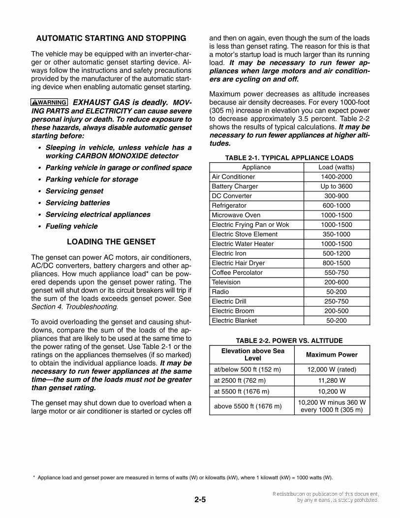
LOADING THE GENSET
The genset can power AC motors, air conditioners,AC/DC converters, battery chargers and other ap-pliances. How much appliance load* can be pow-ered depends upon the genset power rating. Thegenset will shut down or its circuit breakers will trip ifthe sum of the loads exceeds genset power. SeeSection 4. Troubleshooting.
To avoid overloading the genset and causing shut-downs, compare the sum of the loads of the ap-pliances that are likely to be used at the same time tothe power rating of the genset. Use Table 2-1 or theratings on the appliances themselves (if so marked)to obtain the individual appliance loads. It may benecessary to run fewer appliances at the sametime—the sum of the loads must not be greaterthan genset rating.
The genset may shut down due to overload when alarge motor or air conditioner is started or cycles off
and then on again, even though the sum of the loadsis less than genset rating. The reason for this is thata motor’s startup load is much larger than its runningload. It may be necessary to run fewer ap-pliances when large motors and air condition-ers are cycling on and off.
Maximum power decreases as altitude increasesbecause air density decreases. For every 1000-foot(305 m) increase in elevation you can expect powerto decrease approximately 3.5 percent. Table 2-2shows the results of typical calculations. It may benecessary to run fewer appliances at higher alti-tudes.
TABLE 2-1. TYPICAL APPLIANCE LOADSAppliance Load (watts)
Air Conditioner 1400-2000
Battery Charger Up to 3600
DC Converter 300-900
Refrigerator 600-1000
Microwave Oven 1000-1500
Electric Frying Pan or Wok 1000-1500
Electric Stove Element 350-1000
Electric Water Heater 1000-1500
Electric Iron 500-1200
Electric Hair Dryer 800-1500
Coffee Percolator 550-750
Television 200-600
Radio 50-200
Electric Drill 250-750
Electric Broom 200-500
Electric Blanket 50-200
TABLE 2-2. POWER VS. ALTITUDE
Elevation above SeaLevel Maximum Power
at/below 500 ft (152 m) 12,000 W (rated)
at 2500 ft (762 m) 11,280 W
at 5500 ft (1676 m) 10,200 W
above 5500 ft (1676 m) 10,200 W minus 360 Wevery 1000 ft (305 m)
* Appliance load and genset power are measured in terms of watts (W) or kilowatts (kW), where 1 kilowatt (kW) = 1000 watts (W).
2-6
RESETTING CIRCUIT BREAKERS
If a circuit breaker in the main power distributionpanel of the vehicle or on the genset (Figure 2-2)trips, either a circuit shorted or too many applianceswere running. Note that the genset will continue torun after a circuit breaker trips.
If a circuit breaker trips, disconnect or turn off asmany loads as possible and reset the circuit break-er. (Push the circuit breaker to OFF to reset it andthen to ON to reconnect the circuit.) If the circuitbreaker trips right away, either the electrical dis-tribution system has a short or the circuit breaker isfaulty. Call a qualified electrician.
If the circuit breaker does not trip, reconnect the ap-pliances, one by one, up to a total load that does notoverload the genset or cause the circuit breaker totrip. If a circuit breaker trips right away when an ap-pliance is connected, the appliance probably has ashort.
Electrical appliances and tools must be used andmaintained properly and be properly grounded tocause the line circuit breakers to trip when short cir-cuits occur.
WARNING Short circuits in electrical ap-pliances and tools can cause fire and electricalshock leading to severe personal injury ordeath. Read and follow the equipment and toolmanufacturer’s instructions and warnings re-garding use, maintenance and proper ground-ing.
CONNECTING TO UTILITY POWER
A vehicle with provisions for connecting utility powermust have an approved device to keep the gensetand utility from being interconnected. See the gen-set Installation Manual for more information.
WARNING Interconnecting the genset and thepublic utility (or any other power source) canlead to electrocution of utility line workers,equipment damage and fire. Use an approvedswitching device to prevent interconnections.
OPERATING IN COLD WEATHER
Make sure the engine oil viscosity is appropriate forthe cold weather temperatures. See ENGINE OILRECOMMENDATIONS (Page 2-1). Be sure tochange the oil if a sudden drop in temperature oc-curs.
OPERATING IN HOT WEATHER
Pay particular attention to the following items whenoperating the genset in hot weather:
1. Make sure nothing blocks airflow to and fromthe genset.
2. Make sure engine oil viscosity is appropriate forthe ambient temperatures. See ENGINE OILRECOMMENDATIONS (Page 2-1).
3. Keep the genset clean.
4. Perform maintenance due. See PERIODICMAINTENANCE SCHEDULE (Page 3-1).
OPERATING AT HIGH ALTITUDE
For the effect of altitude on maximum power, seeLOADING THE GENSET (Page 2-5).
OPERATING IN DUSTY ENVIRONMENTS
Pay particular attention to the following items whenoperating the genset in dusty environments:
1. Do not let dirt and debris accumulate inside thegenset compartment. Keep the genset clean.
2. Perform air cleaner maintenance more often.See PERIODIC MAINTENANCE SCHEDULE(Page 3-1).
3. Change engine oil more often. See PERIODICMAINTENANCE SCHEDULE (Page 3-1).
4. Keep containers of engine oil that have beenopened tightly closed to keep out dust.
2-7
BREAKING IN A NEW ENGINE
Proper engine break-in on a new genset or on onewith a rebuilt engine is essential for top engine per-formance and acceptable oil consumption. Run thegenset at approximately 1/2 rated power for the first2 hours and then at 3/4 rated power for 2 morehours. See LOADING THE GENSET (Page 2-5).
Proper engine oil and oil level are especially criticalduring break-in because of the higher engine tem-peratures that can be expected. Change the oil if notappropriate for the ambient temperatures duringbreak-in. See ENGINE OIL RECOMMENDATIONS(Page 2-1). Check oil level twice a day or every4 hours during the first 24 hours of operation andchange the oil and oil filter after the first 50 hours ofoperation.
EXERCISING THE GENSET
Exercise the genset at least 2 hours each month ifuse is infrequent. Run the genset at approximately1/2 rated power. See LOADING THE GENSET(Page 2-5). A single two hour exercise period isbetter than several shorter periods.
Exercising a genset drives off moisture, re-lubri-cates the engine, replaces stale fuel and removesoxides from electrical contacts. The result is betterstarting, more reliable operation and longer enginelife.
STORING THE GENSET
Proper storage is essential for preserving top gen-set performance and reliability when the gensetcannot be exercised regularly and will be idle formore than 120 days.
Storing the Genset
1. Disable the automatic genset starting feature ofan inverter-charger or other automatic startingdevice.
WARNING CARBON MONOXIDE is deadlyand can accumulate to dangerous levels ingarages and other confined spaces. Dis-able the automatic genset starting featureof an inverter-charger or other automaticstarting device before storing the vehicle.
2. Push the genset line circuit breaker OFF(Page 2-6).
3. Change the engine oil and attach a tag indicat-ing oil viscosity. See ENGINE OIL REC-OMMENDATIONS (Page 2-1).
4. Disconnect the battery cables (negative [−]cable first) from the starting battery and storethe battery according to the battery manufac-turer’s recommendations. See MAINTAININGTHE BATTERY AND BATTERY CONNEC-TIONS (Page 3-4).
5. Plug the exhaust tail pipe to keep out dirt, mois-ture, bugs, etc.
6. Close the fuel supply valve (if so equipped).
Returning the Genset to Service
1. Check the oil tag on the genset and change theoil if the viscosity indicated is not appropriate forthe temperatures expected. See ENGINE OILRECOMMENDATIONS (Page 2-1).
2. Reconnect the starting battery (negative [−]cable last). See MAINTAINING THE BATTERYAND BATTERY CONNECTIONS (Page 3-4).
3. Remove the plug from the exhaust tailpipe.
4. Change the air filter element if it is dirty(Page 3-4).
5. Open the fuel supply valve (if so equipped).
6. Inspect the genset. See GENERAL INSPEC-TION (Page 3-2).
7. Push the genset line circuit breaker ON(Page 2-6) when the genset is ready to powerappliances.
8. Enable the automatic genset starting feature ofan inverter-charger or other automatic startingdevice following the device manufacturer’s in-structions and safety precautions.

3-1
3. Periodic Maintenance
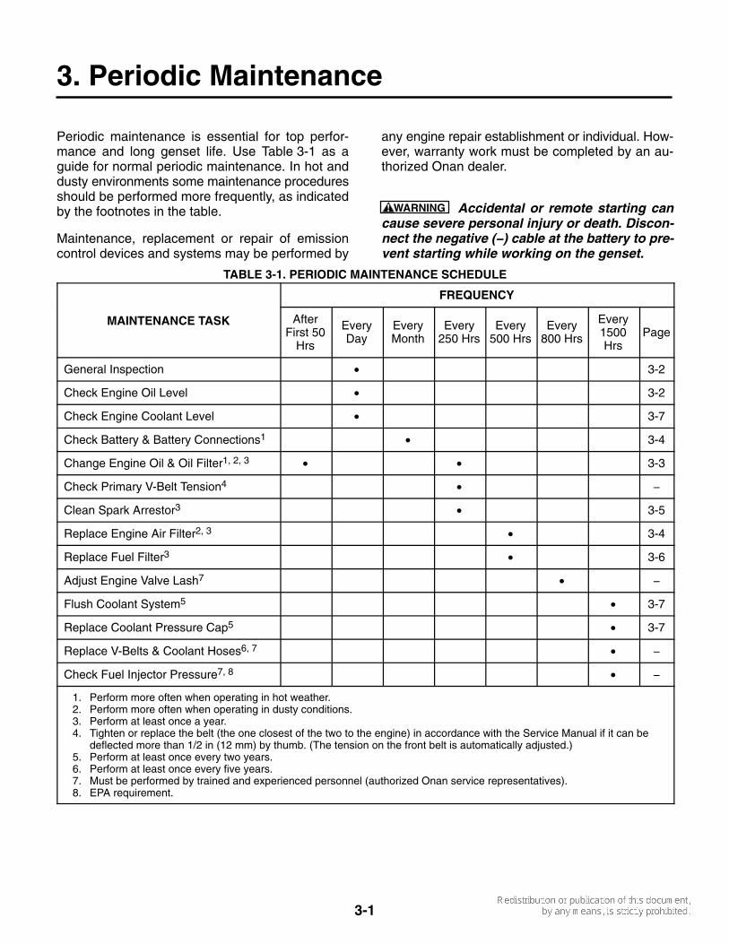
Periodic maintenance is essential for top perfor-mance and long genset life. Use Table 3-1 as aguide for normal periodic maintenance. In hot anddusty environments some maintenance proceduresshould be performed more frequently, as indicatedby the footnotes in the table.
Maintenance, replacement or repair of emissioncontrol devices and systems may be performed by
any engine repair establishment or individual. How-ever, warranty work must be completed by an au-thorized Onan dealer.
WARNING Accidental or remote starting cancause severe personal injury or death. Discon-nect the negative (−) cable at the battery to pre-vent starting while working on the genset.
TABLE 3-1. PERIODIC MAINTENANCE SCHEDULE
FREQUENCY
MAINTENANCE TASK AfterFirst 50
Hrs
EveryDay
EveryMonth
Every250 Hrs
Every500 Hrs
Every800 Hrs
Every1500Hrs
Page
General Inspection • 3-2
Check Engine Oil Level • 3-2
Check Engine Coolant Level • 3-7
Check Battery & Battery Connections1 • 3-4
Change Engine Oil & Oil Filter1, 2, 3 • • 3-3
Check Primary V-Belt Tension4 • −
Clean Spark Arrestor3 • 3-5
Replace Engine Air Filter2, 3 • 3-4
Replace Fuel Filter3 • 3-6
Adjust Engine Valve Lash7 • −
Flush Coolant System5 • 3-7
Replace Coolant Pressure Cap5 • 3-7
Replace V-Belts & Coolant Hoses6, 7 • −
Check Fuel Injector Pressure7, 8 • −
1. Perform more often when operating in hot weather.2. Perform more often when operating in dusty conditions.3. Perform at least once a year.4. Tighten or replace the belt (the one closest of the two to the engine) in accordance with the Service Manual if it can be
deflected more than 1/2 in (12 mm) by thumb. (The tension on the front belt is automatically adjusted.)5. Perform at least once every two years.6. Perform at least once every five years.7. Must be performed by trained and experienced personnel (authorized Onan service representatives).8. EPA requirement.
3-2
GENERAL INSPECTION
Inspect the genset before the first start of the dayand after every eight hours of operation.
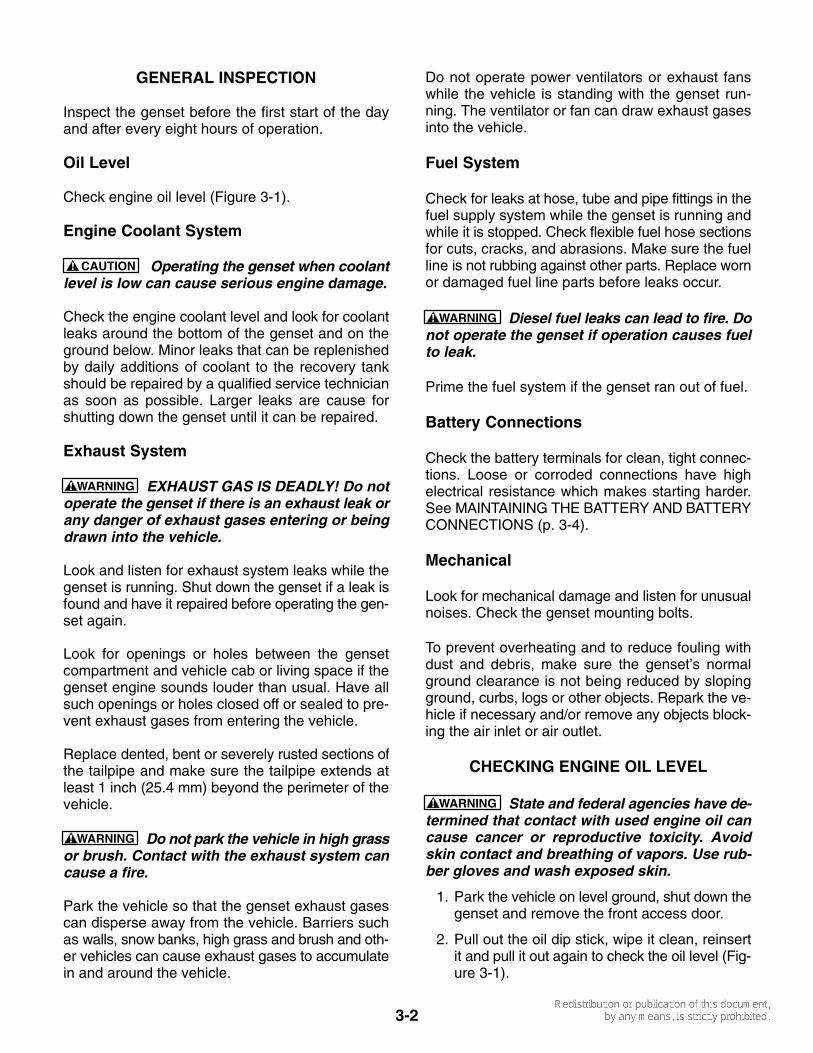
Oil Level
Check engine oil level (Figure 3-1).
Engine Coolant System
CAUTION Operating the genset when coolantlevel is low can cause serious engine damage.
Check the engine coolant level and look for coolantleaks around the bottom of the genset and on theground below. Minor leaks that can be replenishedby daily additions of coolant to the recovery tankshould be repaired by a qualified service technicianas soon as possible. Larger leaks are cause forshutting down the genset until it can be repaired.
Exhaust System
WARNING EXHAUST GAS IS DEADLY! Do notoperate the genset if there is an exhaust leak orany danger of exhaust gases entering or beingdrawn into the vehicle.
Look and listen for exhaust system leaks while thegenset is running. Shut down the genset if a leak isfound and have it repaired before operating the gen-set again.
Look for openings or holes between the gensetcompartment and vehicle cab or living space if thegenset engine sounds louder than usual. Have allsuch openings or holes closed off or sealed to pre-vent exhaust gases from entering the vehicle.
Replace dented, bent or severely rusted sections ofthe tailpipe and make sure the tailpipe extends atleast 1 inch (25.4 mm) beyond the perimeter of thevehicle.
WARNING Do not park the vehicle in high grassor brush. Contact with the exhaust system cancause a fire.
Park the vehicle so that the genset exhaust gasescan disperse away from the vehicle. Barriers suchas walls, snow banks, high grass and brush and oth-er vehicles can cause exhaust gases to accumulatein and around the vehicle.
Do not operate power ventilators or exhaust fanswhile the vehicle is standing with the genset run-ning. The ventilator or fan can draw exhaust gasesinto the vehicle.
Fuel System
Check for leaks at hose, tube and pipe fittings in thefuel supply system while the genset is running andwhile it is stopped. Check flexible fuel hose sectionsfor cuts, cracks, and abrasions. Make sure the fuelline is not rubbing against other parts. Replace wornor damaged fuel line parts before leaks occur.
WARNING Diesel fuel leaks can lead to fire. Donot operate the genset if operation causes fuelto leak.
Prime the fuel system if the genset ran out of fuel.
Battery Connections
Check the battery terminals for clean, tight connec-tions. Loose or corroded connections have highelectrical resistance which makes starting harder.See MAINTAINING THE BATTERY AND BATTERYCONNECTIONS (p. 3-4).
Mechanical
Look for mechanical damage and listen for unusualnoises. Check the genset mounting bolts.
To prevent overheating and to reduce fouling withdust and debris, make sure the genset’s normalground clearance is not being reduced by slopingground, curbs, logs or other objects. Repark the ve-hicle if necessary and/or remove any objects block-ing the air inlet or air outlet.
CHECKING ENGINE OIL LEVEL
WARNING State and federal agencies have de-termined that contact with used engine oil cancause cancer or reproductive toxicity. Avoidskin contact and breathing of vapors. Use rub-ber gloves and wash exposed skin.
1. Park the vehicle on level ground, shut down thegenset and remove the front access door.
2. Pull out the oil dip stick, wipe it clean, reinsertit and pull it out again to check the oil level (Fig-ure 3-1).

3-3
3. Add or drain oil as necessary. See REC-OMMENDED ENGINE OIL (p. 2-1). Keep theoil level between the FULL and ADD marks.
CAUTION Too much oil can cause high oilconsumption. Too little oil can cause severeengine damage. Keep the oil level betweenthe FULL and ADD marks.
4. Reinsert the dipstick and secure the oil fill capand front access door.
CHANGING ENGINE OIL AND OIL FILTER
Refer to Table 3-1 for scheduled engine oil change.Change oil more often in hot and dusty environ-ments.
1. Place a pan under the oil drain plug (Fig-ure 3-1), run the genset until warm and shut itoff.
2. Remove the front access door and the oil fillcap, unscrew the oil drain plug and drain all theoil from the engine. Reinstall the oil drainplug securely.
3. Spin off the oil filter canister and clean the filtermounting surface on the engine block. Removethe old gasket if it remains.
4. Make sure the gasket is in place on the new fil-ter and apply a thin film of clean oil to the gas-ket. Spin the new filter on until the gasket justtouches the block. Turn it an additional 1/2 to3/4 turn. Do not overtighten.
5. Refill with 5.9 quarts (5.6 liters) of oil, check oillevel (Figure 3-1) and secure the front accessdoor.
6. Dispose of the used oil and oil filter accordingto local environmental regulations.
DRAIN PLUG(22 MM HEX HEAD)
DIP STICK
FILTER
FILL CAP
FIGURE 3-1. ENGINE OIL MAINTENANCE
3-4
MAINTAINING THE BATTERY ANDBATTERY CONNECTIONS
WARNING Arcing at battery terminals or inlight switches or other equipment, and flames orsparks, can ignite battery gas causing severepersonal injury—Ventilate battery area beforeworking on or near battery—Wear safetyglasses—Do not smoke—Switch work light ONor OFF away from battery—Stop genset and dis-connect charger before disconnecting batterycables—Disconnect negative (−) cable first andreconnect last.
Refer to Table 3-1 for scheduled battery mainte-nance, and follow the battery manufacturer’s in-structions. Have the battery charging system ser-viced if DC system voltage is consistently low orhigh. Always:
1. Keep the battery case and terminals clean anddry and the terminals tight.
2. Remove battery cables with a battery terminalpuller.
3. Make sure which terminal is positive (+) andwhich is negative (−) before making batteryconnections, always removing the negative (−)cable first and reconnecting it last to reducearcing.
REPLACING THE AIR FILTER ELEMENT
Refer to Table 3-1 for scheduled air filter replace-ment. Replace it more often in dusty environments.
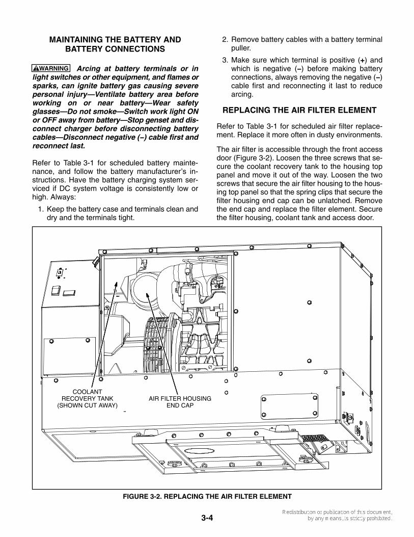
The air filter is accessible through the front accessdoor (Figure 3-2). Loosen the three screws that se-cure the coolant recovery tank to the housing toppanel and move it out of the way. Loosen the twoscrews that secure the air filter housing to the hous-ing top panel so that the spring clips that secure thefilter housing end cap can be unlatched. Removethe end cap and replace the filter element. Securethe filter housing, coolant tank and access door.
AIR FILTER HOUSINGEND CAP
COOLANTRECOVERY TANK
(SHOWN CUT AWAY)
FIGURE 3-2. REPLACING THE AIR FILTER ELEMENT
3-5
CLEANING THE SPARK ARRESTOR
Refer to Table 3-1 for scheduled cleaning of thespark arrestor muffler (which meets U.S. ForestService requirements). Cleaning is required formaximum genset performance.
WARNING A hot muffler can cause severeburns. Let the muffler cool down before remov-ing or installing the cleanout plug.
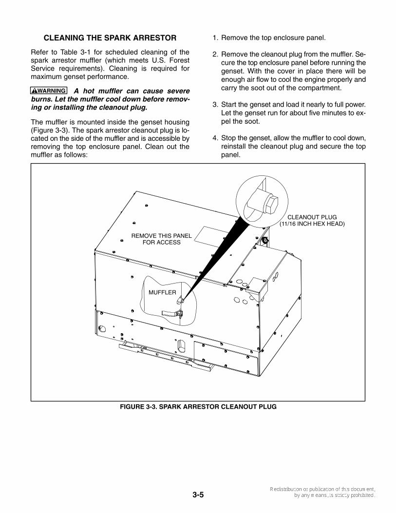
The muffler is mounted inside the genset housing(Figure 3-3). The spark arrestor cleanout plug is lo-cated on the side of the muffler and is accessible byremoving the top enclosure panel. Clean out themuffler as follows:
1. Remove the top enclosure panel.
2. Remove the cleanout plug from the muffler. Se-cure the top enclosure panel before running thegenset. With the cover in place there will beenough air flow to cool the engine properly andcarry the soot out of the compartment.
3. Start the genset and load it nearly to full power.Let the genset run for about five minutes to ex-pel the soot.
4. Stop the genset, allow the muffler to cool down,reinstall the cleanout plug and secure the toppanel.
CLEANOUT PLUG(11/16 INCH HEX HEAD)
REMOVE THIS PANELFOR ACCESS
MUFFLER
FIGURE 3-3. SPARK ARRESTOR CLEANOUT PLUG
3-6
REPLACING THE FUEL FILTER
See Table 3-1 for scheduled fuel filter replacement.A dirty fuel filter may be the cause of a failure to start.The fuel filter is accessible through the front accessdoor (Figure 3-4).
WARNING Diesel fuel is combustible and cancause severe personal injury or death. Do notsmoke near diesel fuel tanks or equipment.Keep flames, sparks, pilot lights, electricalswitches, arc-producing equipment and all oth-er sources of ignition well away. Keep a typeABC fire extinguisher in the vehicle.
Close any fuel line shutoff valve before discon-necting the fuel line from the filter.
Accidental or remote starting can cause severepersonal injury or death. Disconnect the nega-tive (−) cable at the battery to prevent startingwhile working on the genset.
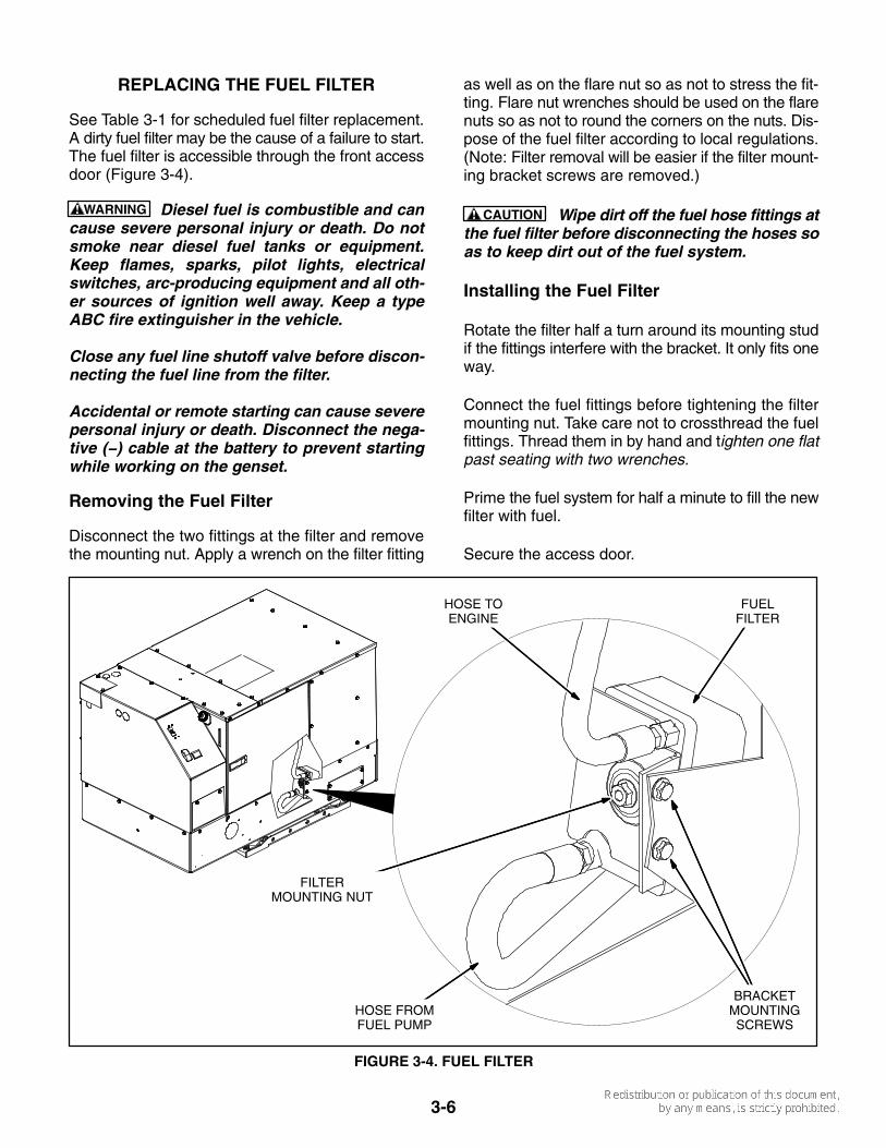
Removing the Fuel Filter
Disconnect the two fittings at the filter and removethe mounting nut. Apply a wrench on the filter fitting
as well as on the flare nut so as not to stress the fit-ting. Flare nut wrenches should be used on the flarenuts so as not to round the corners on the nuts. Dis-pose of the fuel filter according to local regulations.(Note: Filter removal will be easier if the filter mount-ing bracket screws are removed.)
CAUTION Wipe dirt off the fuel hose fittings atthe fuel filter before disconnecting the hoses soas to keep dirt out of the fuel system.
Installing the Fuel Filter
Rotate the filter half a turn around its mounting studif the fittings interfere with the bracket. It only fits oneway.
Connect the fuel fittings before tightening the filtermounting nut. Take care not to crossthread the fuelfittings. Thread them in by hand and tighten one flatpast seating with two wrenches.
Prime the fuel system for half a minute to fill the newfilter with fuel.
Secure the access door.
FUELFILTER
HOSE TOENGINE
HOSE FROMFUEL PUMP
BRACKETMOUNTINGSCREWS
FILTERMOUNTING NUT
FIGURE 3-4. FUEL FILTER

3-7
MAINTAINING THE COOLANT SYSTEM
Refer to Table 3-1 for scheduled maintenance. Theengine cooling system is filled with a 50/50 mixtureof ethylene glycol anti-freeze and water when thegenset leaves the factory, which is suitable for tem-peratures down to -34° F (-37° C).
Recommended Coolant
See RECOMMENDED COOLANT (p. 2-1).
Pressure Cap
Replace the pressure cap (Figure 3-5) every twoyears (seals deteriorate and leak). Proper coolingsystem pressure (14 psi) is essential for optimal en-gine cooling and minimal coolant loss.
Draining and Cleaning Cooling System
WARNING Hot coolant spray can cause severeburns. Let the engine cool before releasing thepressure cap or removing the drain cap.
Accidental or remote starting can cause severepersonal injury or death. Disconnect the nega-tive (−) cable at the battery to prevent startingwhile working on the genset.
Let the engine cool before removing the pressurecap. Relieve any remaining pressure by turning thepressure cap slowly, without pushing down. Whenthe pressure has been relieved, push down on the
cap, turn it the rest of the way and withdraw it. Thenremove the coolant drain plug (Figure 3-5) anddrain the coolant into a suitable container.
WARNING Ethylene glycol antifreeze is con-sidered toxic. Dispose of it according to localregulations for hazardous substances.
Flush and clean the cooling system before refilling.Radiator cleaning chemicals are available at localauto parts stores. Follow the instructions for clean-ing and flushing that come with the cleaning solu-tion.
Refilling Cooling System
Install the coolant drain plug using pipe thread seal-ant. Tighten it just enough so that it does not leakwhen the genset is running and has warmed up. Pullthe hose connected to the pressure cap assemblyout as far and as high as it will go and fill the systemwith coolant. When the coolant level reaches the fillopening, start and operate the genset for a few min-utes and shut it down. Add more coolant if neces-sary and secure the pressure cap.
Fill the recovery tank with coolant mixture to theCOLD mark.
Coolant Level Check
Check coolant level in the recovery tank (Fig-ure 3-5) before the first startup of each day and fill tothe COLD mark if necessary.
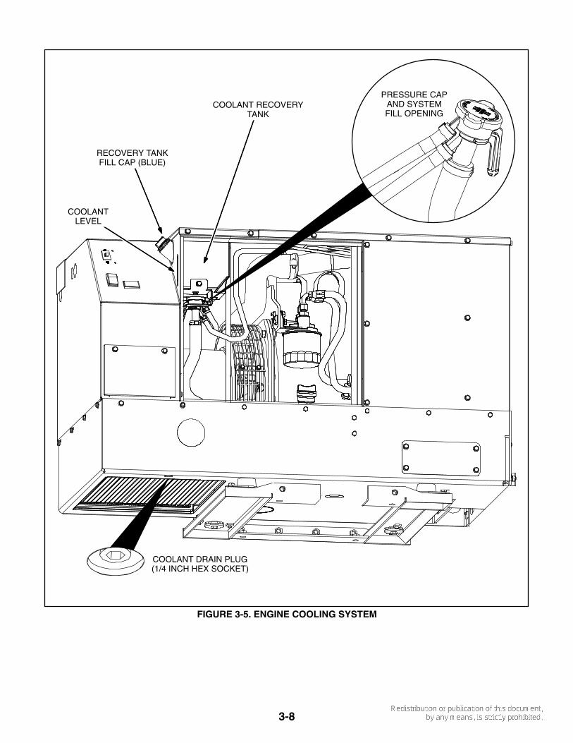
3-8
PRESSURE CAPAND SYSTEMFILL OPENING
COOLANT DRAIN PLUG(1/4 INCH HEX SOCKET)
COOLANT RECOVERYTANK
RECOVERY TANKFILL CAP (BLUE)
COOLANTLEVEL
FIGURE 3-5. ENGINE COOLING SYSTEM
4-1
4. Troubleshooting
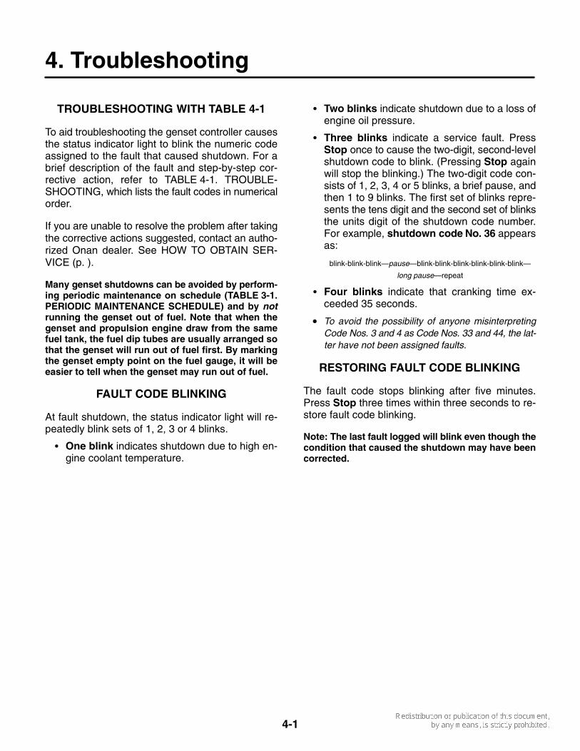
TROUBLESHOOTING WITH TABLE 4-1
To aid troubleshooting the genset controller causesthe status indicator light to blink the numeric codeassigned to the fault that caused shutdown. For abrief description of the fault and step-by-step cor-rective action, refer to TABLE 4-1. TROUBLE-SHOOTING, which lists the fault codes in numericalorder.
If you are unable to resolve the problem after takingthe corrective actions suggested, contact an autho-rized Onan dealer. See HOW TO OBTAIN SER-VICE (p. ).
Many genset shutdowns can be avoided by perform-ing periodic maintenance on schedule (TABLE 3-1.PERIODIC MAINTENANCE SCHEDULE) and by notrunning the genset out of fuel. Note that when thegenset and propulsion engine draw from the samefuel tank, the fuel dip tubes are usually arranged sothat the genset will run out of fuel first. By markingthe genset empty point on the fuel gauge, it will beeasier to tell when the genset may run out of fuel.
FAULT CODE BLINKING
At fault shutdown, the status indicator light will re-peatedly blink sets of 1, 2, 3 or 4 blinks.
� One blink indicates shutdown due to high en-gine coolant temperature.
� Two blinks indicate shutdown due to a loss ofengine oil pressure.
� Three blinks indicate a service fault. PressStop once to cause the two-digit, second-levelshutdown code to blink. (Pressing Stop againwill stop the blinking.) The two-digit code con-sists of 1, 2, 3, 4 or 5 blinks, a brief pause, andthen 1 to 9 blinks. The first set of blinks repre-sents the tens digit and the second set of blinksthe units digit of the shutdown code number.For example, shutdown code No. 36 appearsas:
blink-blink-blink—pause—blink-blink-blink-blink-blink-blink—
long pause—repeat
� Four blinks indicate that cranking time ex-ceeded 35 seconds.
• To avoid the possibility of anyone misinterpretingCode Nos. 3 and 4 as Code Nos. 33 and 44, the lat-ter have not been assigned faults.
RESTORING FAULT CODE BLINKING
The fault code stops blinking after five minutes.Press Stop three times within three seconds to re-store fault code blinking.
Note: The last fault logged will blink even though thecondition that caused the shutdown may have beencorrected.

4-2
TABLE 4-1. TROUBLESHOOTING
Some genset service procedures present hazards that can result in severe per-sonal injury or death. Only trained and experienced service personnel with knowledge of fuels,electricity, and machinery hazards should perform genset service. See Safety Precautions.
WARNING
NO RESPONSE AT CONTROL SWITCH(Faulty switch, poor or missing connections, dead battery)
Corrective Action: 1. Try the genset (local) control switch if there is no response at the remote control switch, and vice
versa.2. Check for 12 VDC across genset battery cable terminal block. Service as necessary by cleaning and
tightening battery cable connections, recharging or replacing the battery or replacing damaged ormissing battery cables.
THE STARTER ENGAGES AND DISENGAGES(Low cranking voltage)
Corrective Action: 1. Have the vehicle propulsion engine running while trying to start the genset. Its charging alternator
may be able to maintain a high enough battery terminal voltage to start the genset.2. Service the battery as necessary by cleaning and tightening connections, recharging or replacing
the battery or replacing damaged battery cables.
THE STARTING BATTERIES DO NOT MAINTAIN A CHARGE(Marginal battery, battery connections or charging system)
Corrective Action: Service the battery as necessary by cleaning and tightening connections, recharg-ing or replacing the battery or replacing damaged battery cables.
1. Have the battery recharging system serviced.
NO AC POWER WHEN GENSET IS RUNNING(A Circuit Breaker is OFF, tripped or malfunctioning or there are poor AC harness connections)
Corrective Action: 1. Reset or turn ON genset circuit breaker CB1.2. Reset or turn ON any other circuit breaker in the AC power supply system.
ENGINE OVER TEMPERATURE—CODE NO. 1(During normal operation engine coolant temperature exceeded 239° F [115° C] for 10 seconds)
Corrective Action: 1. Check engine coolant level, add coolant as necessary and repair any leaks.2. Check for and remove any objects blocking the air inlet or outlet openings in the bottom of the genset
and clean out dirt fouling the radiator passages.3. Run fewer appliances at the same time to keep down engine temperature. (Note that high altitude
and high ambient temperature decrease engine cooling capacity.)4. Look for loose or broken fan belts and have them serviced.
4-3
TABLE 4-1. TROUBLESHOOTING
Some genset service procedures present hazards that can result in severe per-sonal injury or death. Only trained and experienced service personnel with knowledge of fuels,electricity, and machinery hazards should perform genset service. See Safety Precautions.
WARNING
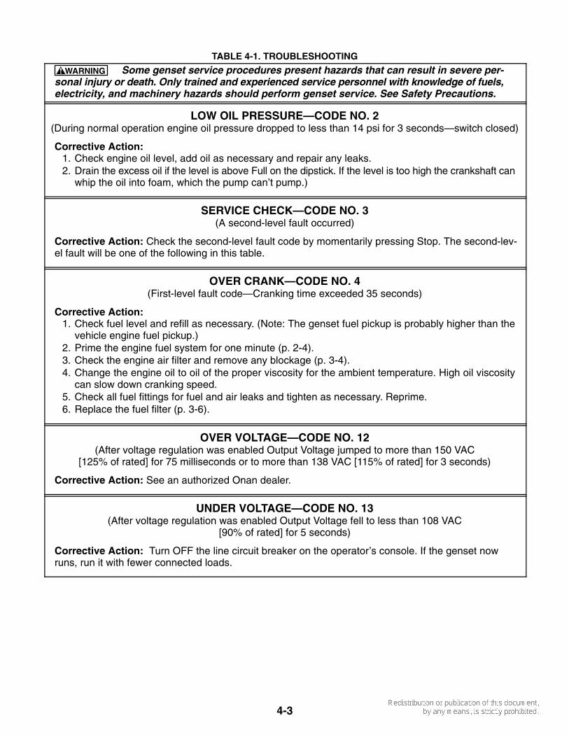
LOW OIL PRESSURE—CODE NO. 2(During normal operation engine oil pressure dropped to less than 14 psi for 3 seconds—switch closed)
Corrective Action: 1. Check engine oil level, add oil as necessary and repair any leaks.2. Drain the excess oil if the level is above Full on the dipstick. If the level is too high the crankshaft can
whip the oil into foam, which the pump can’t pump.)
SERVICE CHECK—CODE NO. 3(A second-level fault occurred)
Corrective Action: Check the second-level fault code by momentarily pressing Stop. The second-lev-el fault will be one of the following in this table.
OVER CRANK—CODE NO. 4(First-level fault code—Cranking time exceeded 35 seconds)
Corrective Action: 1. Check fuel level and refill as necessary. (Note: The genset fuel pickup is probably higher than the
vehicle engine fuel pickup.)2. Prime the engine fuel system for one minute (p. 2-4).3. Check the engine air filter and remove any blockage (p. 3-4).4. Change the engine oil to oil of the proper viscosity for the ambient temperature. High oil viscosity
can slow down cranking speed.5. Check all fuel fittings for fuel and air leaks and tighten as necessary. Reprime.6. Replace the fuel filter (p. 3-6).
OVER VOLTAGE—CODE NO. 12(After voltage regulation was enabled Output Voltage jumped to more than 150 VAC
[125% of rated] for 75 milliseconds or to more than 138 VAC [115% of rated] for 3 seconds)
Corrective Action: See an authorized Onan dealer.
UNDER VOLTAGE—CODE NO. 13(After voltage regulation was enabled Output Voltage fell to less than 108 VAC
[90% of rated] for 5 seconds)
Corrective Action: Turn OFF the line circuit breaker on the operator’s console. If the genset nowruns, run it with fewer connected loads.

4-4
TABLE 4-1. TROUBLESHOOTING
Some genset service procedures present hazards that can result in severe per-sonal injury or death. Only trained and experienced service personnel with knowledge of fuels,electricity, and machinery hazards should perform genset service. See Safety Precautions.
WARNING
OVER FREQUENCY—CODE NO. 14(After the starter was engaged Frequency jumped to more than 70 Hz
for 40 milliseconds or to more than 66 Hz for 6 seconds)
Corrective Action: 1. Check for a tripped genset circuit breaker, reset it if necessary, and run with fewer connected loads.
(A breaker tripping under load can cause genset frequency to overshoot.)2. Check all fuel fittings for fuel and air leaks and tighten as necessary. Reprime. (Air bubbles can
disrupt frequency.)
UNDER FREQUENCY—CODE NO. 15(During normal operation Frequency fell to less than 54 Hz for more than 8 seconds)
Corrective Action: 1. Push the line circuit breaker to OFF and restart the genset. If the genset now runs, run it with fewer
connected loads, especially those with high motor starting loads such as air conditioners.2. Check all fuel fittings for fuel and air leaks and tighten as necessary. Reprime. (Air bubbles can dis-
rupt frequency.)3. Replace the engine air filter and clean the spark-arrest muffler (p. 3-4).4. Replace the fuel filter (p. 3-6).
ACTUATOR SHORTED OR OPEN—CODE NO. 19(At startup the Controller sensed an open or shorted governor actuator/harness)
Corrective Action: See an authorized Onan dealer.
ACTUATOR OVERLOAD—CODE NO. 22(Due to connected overload or low engine performance, the Controller maintained the governor actuator
at full-duty cycle—maximum pulse-width-modulated square-wave signal [PWM]—for60 consecutive seconds)
Corrective Action: 1. Reduce the number of appliances running at the same time, especially those with high motor starting
loads such as air conditioners.2. Check all fuel fittings for fuel and air leaks and tighten as necessary. Reprime.3. Replace the engine air filter and clean the spark-arrest muffler (p. 3-4).4. Replace the fuel filter (p. 3-6).
FAULTY ENGINE TEMPERATURE SENDER—CODE NO. 24(After 10 minutes of normal operation the Controller checked for and sensed
an open temperature sender/harness)
Corrective Action: See an authorized Onan dealer.
4-5
TABLE 4-1. TROUBLESHOOTING
Some genset service procedures present hazards that can result in severe per-sonal injury or death. Only trained and experienced service personnel with knowledge of fuels,electricity, and machinery hazards should perform genset service. See Safety Precautions.
WARNING
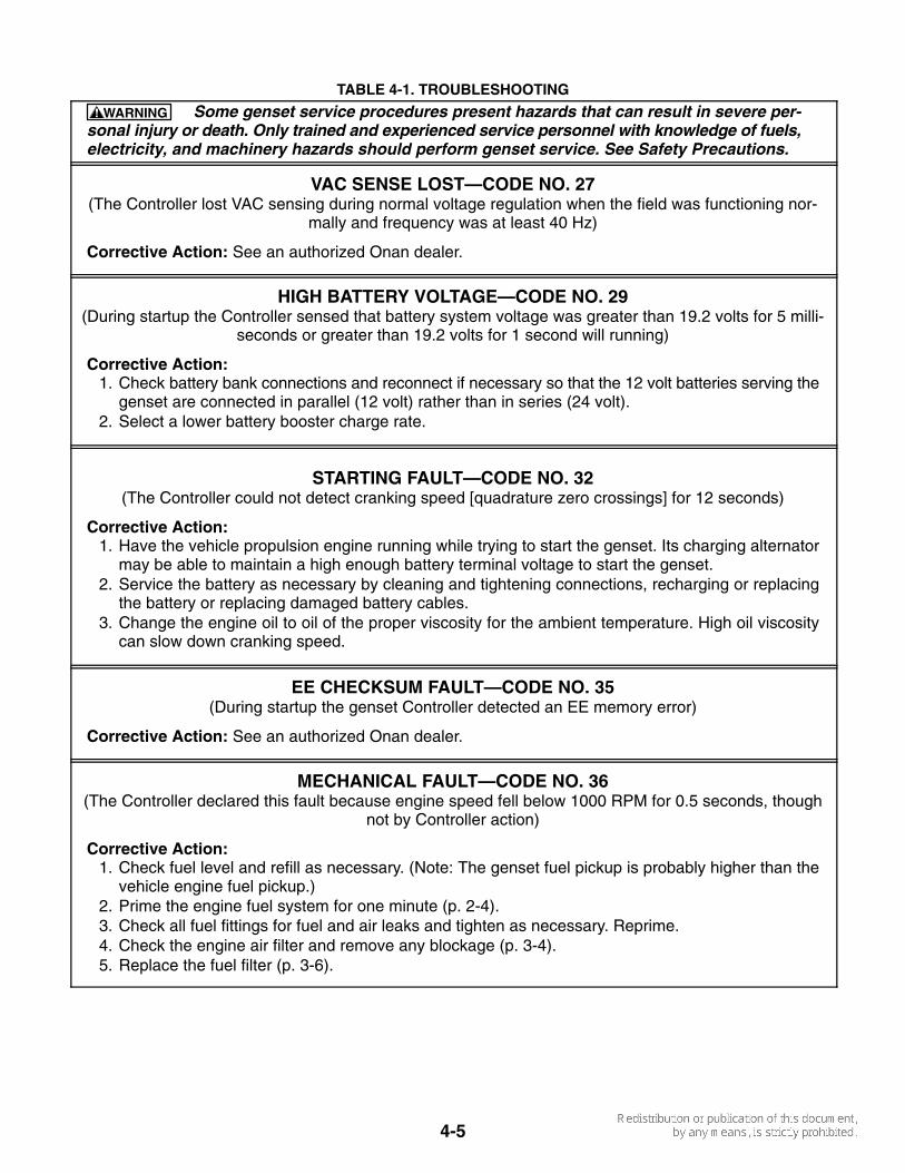
VAC SENSE LOST—CODE NO. 27(The Controller lost VAC sensing during normal voltage regulation when the field was functioning nor-
mally and frequency was at least 40 Hz)
Corrective Action: See an authorized Onan dealer.
HIGH BATTERY VOLTAGE—CODE NO. 29(During startup the Controller sensed that battery system voltage was greater than 19.2 volts for 5 milli-
seconds or greater than 19.2 volts for 1 second will running)
Corrective Action: 1. Check battery bank connections and reconnect if necessary so that the 12 volt batteries serving the
genset are connected in parallel (12 volt) rather than in series (24 volt).2. Select a lower battery booster charge rate.
STARTING FAULT—CODE NO. 32(The Controller could not detect cranking speed [quadrature zero crossings] for 12 seconds)
Corrective Action: 1. Have the vehicle propulsion engine running while trying to start the genset. Its charging alternator
may be able to maintain a high enough battery terminal voltage to start the genset.2. Service the battery as necessary by cleaning and tightening connections, recharging or replacing
the battery or replacing damaged battery cables.3. Change the engine oil to oil of the proper viscosity for the ambient temperature. High oil viscosity
can slow down cranking speed.
EE CHECKSUM FAULT—CODE NO. 35(During startup the genset Controller detected an EE memory error)
Corrective Action: See an authorized Onan dealer.
MECHANICAL FAULT—CODE NO. 36(The Controller declared this fault because engine speed fell below 1000 RPM for 0.5 seconds, though
not by Controller action)
Corrective Action: 1. Check fuel level and refill as necessary. (Note: The genset fuel pickup is probably higher than the
vehicle engine fuel pickup.)2. Prime the engine fuel system for one minute (p. 2-4).3. Check all fuel fittings for fuel and air leaks and tighten as necessary. Reprime.4. Check the engine air filter and remove any blockage (p. 3-4).5. Replace the fuel filter (p. 3-6).

4-6
TABLE 4-1. TROUBLESHOOTING
Some genset service procedures present hazards that can result in severe per-sonal injury or death. Only trained and experienced service personnel with knowledge of fuels,electricity, and machinery hazards should perform genset service. See Safety Precautions.
WARNING
FIELD OVERLOAD—CODE NO. 38(During normal voltage regulation Field Voltage exceeded 180 VAC for 10 seconds)
Corrective Action: 1. Reduce the number of air conditioners running at the same time, and other appliances that cause
low power factor. (The lower the power factor of a motor or compressor, the more current it drawsper kilowatt. The genset Controller, in turn, must boost field voltage to meet the higher demand forcurrent imposed by low power factor.)
2. Have the air conditioners and other appliances checked for proper operation. (A locked compressorrotor can cause a very low power factor.)
GENERATOR ROTOR SHORT—CODE NO. 41(While flashing the field the Controller sensed that the rotor circuit was shorted to ground)
Corrective Action: See an authorized Onan dealer.
ROM FAULT—CODE NO. 42(During startup the genset Controller detected a ROM memory error)
Corrective Action: See an authorized Onan dealer.
RAM FAULT—CODE NO. 43(During startup the genset Controller detected a RAM memory error)
Corrective Action: See an authorized Onan dealer.
SPEED SENSE LOST—CODE NO. 45(After start disconnect the Controller lost speed sense [quadrature zero crossings] for 0.25 seconds)
Corrective Action: See an authorized Onan dealer.
LOSS OF FIELD SENSE—CODE NO. 48(The field sense circuit on the Controller circuit board failed during normal voltage regulation)
Corrective Action: See an authorized Onan dealer.
OVERPRIME—CODE NO. 57(The local or remote control switch was held in the Prime position for more than 3 minutes)
Corrective Action: Check for and remove any object that may be holding either control switch (remoteor local) in the prime position.
5-1
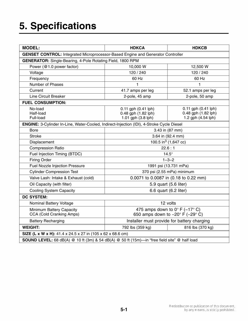
5. Specifications
MODEL: HDKCA HDKCB
GENSET CONTROL: Integrated Microprocessor-Based Engine and Generator Controller
GENERATOR: Single-Bearing, 4-Pole Rotating Field, 1800 RPM
Power (@1.0 power factor) 10,000 W 12,500 W
Voltage 120 / 240 120 / 240
Frequency 60 Hz 60 Hz
Number of Phases 1 1
Current 41.7 amps per leg 52.1 amps per leg
Line Circuit Breaker 2-pole, 45 amp 2-pole, 50 amp
FUEL CONSUMPTION:
No-loadHalf-loadFull-load
0.11 gph (0.41 lph)0.48 gph (1.82 lph)1.01 gph (3.8 lph)
0.11 gph (0.41 lph)0.48 gph (1.82 lph)1.2 gph (4.54 lph)
ENGINE: 3-Cylinder In-Line, Water-Cooled, Indirect-Injection (IDI), 4-Stroke Cycle Diesel
Bore 3.43 in (87 mm)
Stroke 3.64 in (92.4 mm)
Displacement 100.5 in3 (1,647 cc)
Compression Ratio 22.6 : 1
Fuel Injection Timing (BTDC) 14.5°Firing Order 1−3−2
Fuel Nozzle Injection Pressure 1991 psi (13.731 mPa)
Cylinder Compression Test 370 psi (2.55 mPa) minimum
Valve Lash: Intake & Exhaust (cold) 0.0071 to 0.0087 in (0.18 to 0.22 mm)Oil Capacity (with filter) 5.9 quart (5.6 liter)Cooling System Capacity 6.6 quart (6.2 liter)
DC SYSTEM:
Nominal Battery Voltage 12 voltsMinimum Battery CapacityCCA (Cold Cranking Amps)
475 amps down to 0° F (−17° C)650 amps down to −20° F (−29° C)
Battery Recharging Installer must provide for battery chargingWEIGHT: 792 lbs (359 kg) 816 lbs (370 kg)
SIZE (L x W x H): 41.4 x 24.5 x 27 in (105 x 62 x 68.6 cm)
SOUND LEVEL: 68 dB(A) @ 10 ft (3m) & 54 dB(A) @ 50 ft (15m)—in “free field site” @ half load

6-1
6. Maintenance Record
Record all periodic and unscheduled maintenance and service. See Section 3. Periodic Maintenance.
DATEHOURMETER
READINGMAINTENANCE OR SERVICE PERFORMED
Record the name, address, and phone number of your authorized Onan service center.


Cummins Power Generation1400 73rd Avenue N.E.Minneapolis, MN 55432763-574-5000Fax: 763-528-7229
Cummins and Onan are registered trademarks of Cummins Inc.