Embed Size (px)
Citation preview

ON-VEHICLE REPAIR > CYLINDER HEAD > REMOVAL AND INSTALLATION >
INSTALLATION
1. Install new cylinder head gasket.
2. Install cylinder head follow the steps below to tighten cylinder head bolts in numerical
order as shown.
CAUTION: If cylinder head bolts re-used, check their outer diameters
before installation. Follow the "Cylinder Head Bolts Outer Diameter" procedure.
NOTE: Apply new engine oil to threads and seating surfaces of mounting
bolts.
Fig 1: Identifying Intake Side And Exhaust Side Bolt Remove Sequence
Courtesy of NISSAN MOTOR CO., U.S.A.
Tool number : KV10112100 (BT8653-A)
Step a : 50 N.m (5.1 kg-m, 37 ft-lb)
2008 Nissan Frontier 2.5L Eng SE
Service Manual: ENGINE MECHANICAL
(QR25DE)
Print Date: 11/5/2016
Page 1 of 20Printer Friendly View
11/5/2016http://www1.prodemand.com/Print/Index?content=tabs&module=true&tab=true&terms=tr...

Step b : 60° clockwise
Step c : Loosen to 0 N.m in the reverse order of tightening.
Step d : 39.2 N.m (4.0 kg-m, 29 ft-lb)
Step e : 75° clockwise
Step f : 75° clockwise
Fig 2: Tightening Cylinder Head Bolts
Courtesy of NISSAN MOTOR CO., U.S.A.
3. Installation of the remaining components is in reverse order of removal.
DISASSEMBLY AND ASSEMBLY > ENGINE UNIT > DISASSEMBLY AND
ASSEMBLY > ASSEMBLY
1. Using compressed air, clean out the coolant and oil passages in the cylinder block, the
cylinder bore and the crankcase to remove any foreign material.
CAUTION: Use approved safety glasses to protect your eyes.
Page 2 of 20Printer Friendly View
11/5/2016http://www1.prodemand.com/Print/Index?content=tabs&module=true&tab=true&terms=tr...

2. Apply Silicone RTV Sealant to the drain plugs. Install the drain plugs on the cylinder
block.
1. Use Genuine Silicone RTV Sealant, or equivalent. Refer to "RECOMMENDED
CHEMICAL PRODUCTS AND SEALANTS ".
2. Replace the copper washers with new ones.
Fig 1: Cylinder Block With Torque Specification
Courtesy of NISSAN MOTOR CO., U.S.A.
3. Install the main bearings and the thrust bearings.
a. Remove dust, dirt, and oil from the bearing mating surfaces of the cylinder
block and lower cylinder block.
b. Install the thrust bearings to both sides of the No. 3 main bearing journal on
the cylinder block.
a. Install the thrust bearings with the oil groove facing the crankshaft arm
(outside).
Page 3 of 20Printer Friendly View
11/5/2016http://www1.prodemand.com/Print/Index?content=tabs&module=true&tab=true&terms=tr...
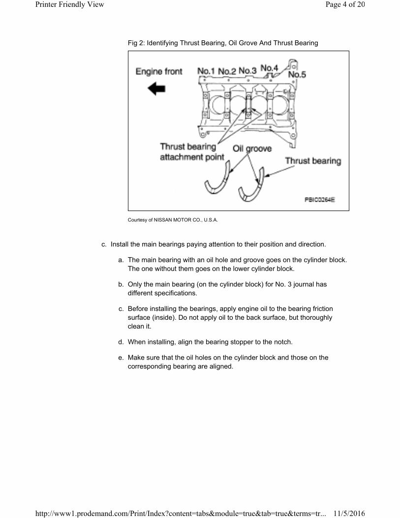
Fig 2: Identifying Thrust Bearing, Oil Grove And Thrust Bearing
Courtesy of NISSAN MOTOR CO., U.S.A.
c. Install the main bearings paying attention to their position and direction.
a. The main bearing with an oil hole and groove goes on the cylinder block.
The one without them goes on the lower cylinder block.
b. Only the main bearing (on the cylinder block) for No. 3 journal has
different specifications.
c. Before installing the bearings, apply engine oil to the bearing friction
surface (inside). Do not apply oil to the back surface, but thoroughly
clean it.
d. When installing, align the bearing stopper to the notch.
e. Make sure that the oil holes on the cylinder block and those on the
corresponding bearing are aligned.
Page 4 of 20Printer Friendly View
11/5/2016http://www1.prodemand.com/Print/Index?content=tabs&module=true&tab=true&terms=tr...

Fig 3: Identifying Cylinder Block Side, Thrust Bearing And Oil Hole
Courtesy of NISSAN MOTOR CO., U.S.A.
4. Install the signal plate to the crankshaft.
a. Position the crankshaft and signal plate using a positioning dowel pin, and
tighten the signal plate bolts to specification.
Signal plate bolts
Type 1 : 18.5 N.m (1.9 kg-m, 14 ft-lb)
Type 2 : 22.0 N.m (2.2 kg-m, 16 ft-lb)
Page 5 of 20Printer Friendly View
11/5/2016http://www1.prodemand.com/Print/Index?content=tabs&module=true&tab=true&terms=tr...
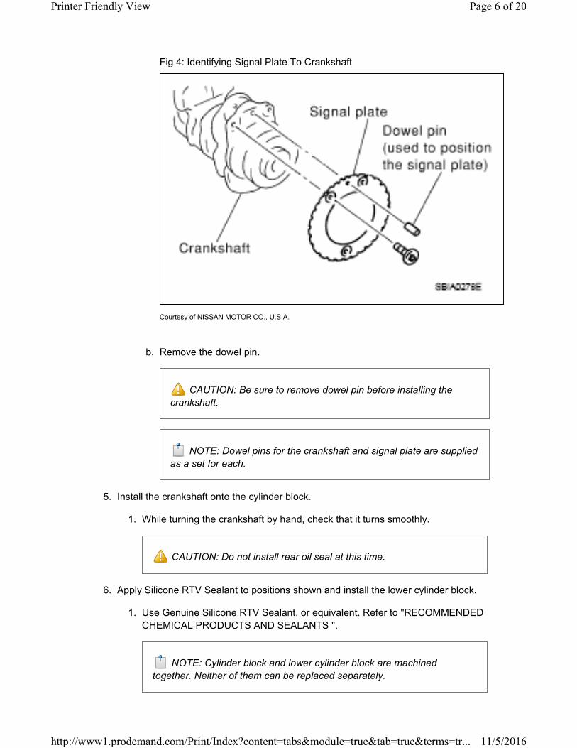
Fig 4: Identifying Signal Plate To Crankshaft
Courtesy of NISSAN MOTOR CO., U.S.A.
b. Remove the dowel pin.
CAUTION: Be sure to remove dowel pin before installing the
crankshaft.
NOTE: Dowel pins for the crankshaft and signal plate are supplied
as a set for each.
5. Install the crankshaft onto the cylinder block.
1. While turning the crankshaft by hand, check that it turns smoothly.
CAUTION: Do not install rear oil seal at this time.
6. Apply Silicone RTV Sealant to positions shown and install the lower cylinder block.
1. Use Genuine Silicone RTV Sealant, or equivalent. Refer to "RECOMMENDED
CHEMICAL PRODUCTS AND SEALANTS ".
NOTE: Cylinder block and lower cylinder block are machined
together. Neither of them can be replaced separately.
Page 6 of 20Printer Friendly View
11/5/2016http://www1.prodemand.com/Print/Index?content=tabs&module=true&tab=true&terms=tr...

CAUTION: After the Silicone RTV Sealant is applied, the lower
cylinder block installation must be finished within 5 minutes.
Fig 5: Identifying Silicone RTV Sealant To Positions
Courtesy of NISSAN MOTOR CO., U.S.A.
7. Tighten lower cylinder block bolts in three steps in the order as shown; Using Tool.
CAUTION: There are more processes to complete the tightening of lower
cylinder bolts. However stop procedure after step 1 and install rear oil seal.
Lower cylinder block bolts
Step 1 (bolts 11 - 22) : 25.1 N.m (2.6 kg-m, 19 ft-lb)
Step 2 (bolts 1 - 10) : 39.2 N.m (4.0 kg-m, 29 ft-lb)
Step 3 (bolts 1 - 10) : 60° - 65° (target: 60°)
Page 7 of 20Printer Friendly View
11/5/2016http://www1.prodemand.com/Print/Index?content=tabs&module=true&tab=true&terms=tr...

Fig 6: Identifying Lower Cylinder Block Bolts Tightening Sequence
Courtesy of NISSAN MOTOR CO., U.S.A.
Install rear oil seal using a suitable drift.
CAUTION:
1. Do not touch grease applied onto oil seal lip.
2. Be careful not to damage crankshaft and/or cylinder block.
3. Press fit oil seal straight to avoid causing burrs or tilting.
Page 8 of 20Printer Friendly View
11/5/2016http://www1.prodemand.com/Print/Index?content=tabs&module=true&tab=true&terms=tr...

Fig 7: Pressing Oil Seal
Courtesy of NISSAN MOTOR CO., U.S.A.
Fig 8: Identifying Cylinder Block Rear End Surface Dimension
Courtesy of NISSAN MOTOR CO., U.S.A.
NOTE:
Page 9 of 20Printer Friendly View
11/5/2016http://www1.prodemand.com/Print/Index?content=tabs&module=true&tab=true&terms=tr...

1. Apply new engine oil to threads and seat surfaces of the bolts.
CAUTION: Check tightening angle using Tool. Do not tighten by visual
inspection.
Tool number : KV10112100 (BT-8653-A)
1. Wipe off completely any protruding Silicone RTV Sealant on the exterior of engine.
2. Check crankshaft side clearance. Refer to "STANDARD AND LIMIT ".
3. After installing the bolts, make sure that the crankshaft can be rotated smoothly by
hand.
Fig 9: Tightening Crankshaft Bolts
Courtesy of NISSAN MOTOR CO., U.S.A.
8. Apply new engine oil to new oil seal and install it using a suitable tool.
1. Install new oil seal in the direction shown.
Page 10 of 20Printer Friendly View
11/5/2016http://www1.prodemand.com/Print/Index?content=tabs&module=true&tab=true&terms=tr...
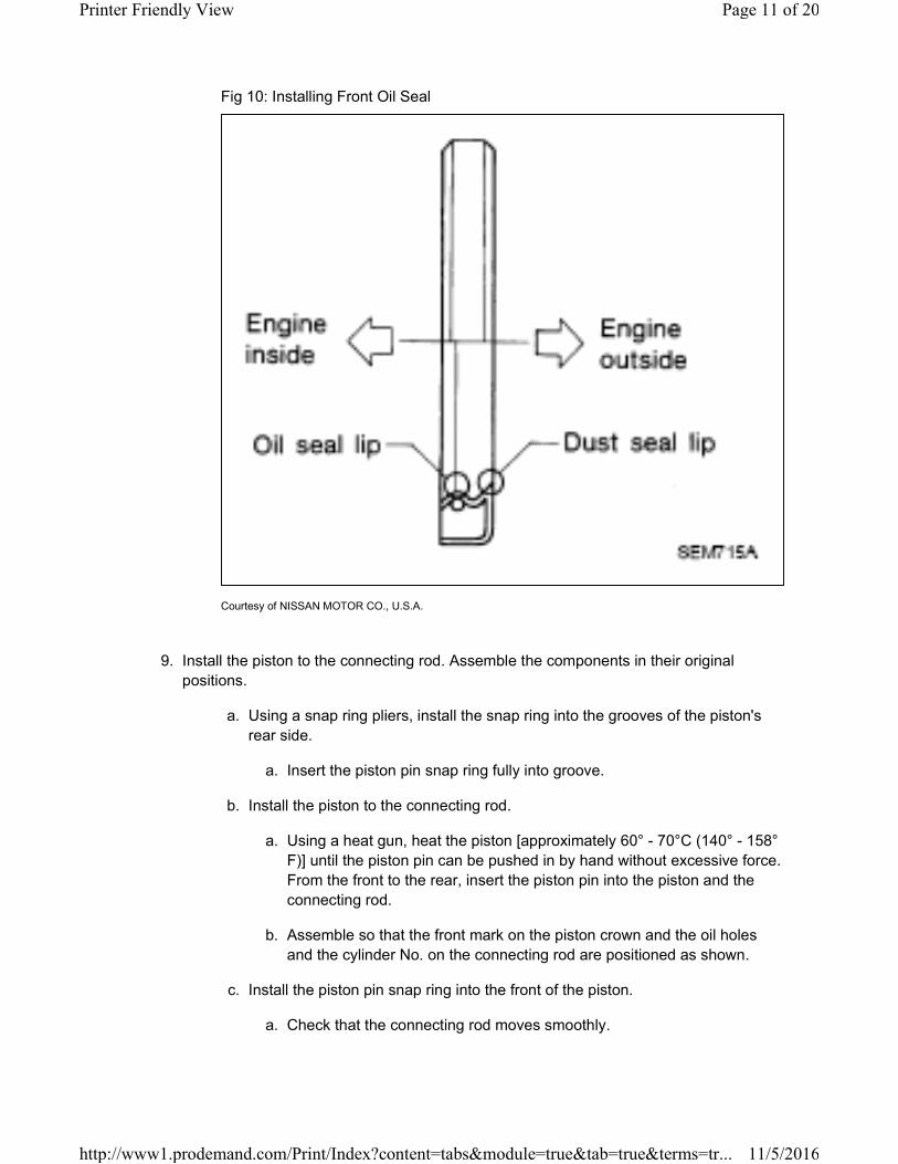
Fig 10: Installing Front Oil Seal
Courtesy of NISSAN MOTOR CO., U.S.A.
9. Install the piston to the connecting rod. Assemble the components in their original
positions.
a. Using a snap ring pliers, install the snap ring into the grooves of the piston's
rear side.
a. Insert the piston pin snap ring fully into groove.
b. Install the piston to the connecting rod.
a. Using a heat gun, heat the piston [approximately 60° - 70°C (140° - 158°
F)] until the piston pin can be pushed in by hand without excessive force.
From the front to the rear, insert the piston pin into the piston and the
connecting rod.
b. Assemble so that the front mark on the piston crown and the oil holes
and the cylinder No. on the connecting rod are positioned as shown.
c. Install the piston pin snap ring into the front of the piston.
a. Check that the connecting rod moves smoothly.
Page 11 of 20Printer Friendly View
11/5/2016http://www1.prodemand.com/Print/Index?content=tabs&module=true&tab=true&terms=tr...

Fig 11: Identifying Connecting Rod And Piston Mark
Courtesy of NISSAN MOTOR CO., U.S.A.
10. Using a piston ring expander, install the piston rings. Assemble the components in their
original positions.
CAUTION: Be careful not to damage the piston.
1. Position each ring with the gap as shown, referencing the piston front mark as the
starting point.
2. Install the top ring and the second ring with the stamped surface facing upward.
Stamped mark : 2ND (second ring)
Page 12 of 20Printer Friendly View
11/5/2016http://www1.prodemand.com/Print/Index?content=tabs&module=true&tab=true&terms=tr...

Fig 12: Identifying Piston Ring Expander
Courtesy of NISSAN MOTOR CO., U.S.A.
11. Install the connecting rod bearings to the connecting rod and the connecting rod cap.
Assemble the components in their original positions.
1. When installing the connecting rod bearings, apply engine oil to the bearing friction
surface (inside). Do not apply oil to the back surface, but thoroughly clean the
back.
2. When installing, align the connecting rod bearing stopper protrusion with the notch
of the connecting rod to install.
3. Check the oil holes on the connecting rod and those on the corresponding bearing
are aligned.
Page 13 of 20Printer Friendly View
11/5/2016http://www1.prodemand.com/Print/Index?content=tabs&module=true&tab=true&terms=tr...

Fig 13: Identifying Connecting Rod Bearings
Courtesy of NISSAN MOTOR CO., U.S.A.
12. Install the piston and connecting rod assembly to the crankshaft. Assemble the
components in their original positions.
1. Rotate the crankshaft so the pin corresponding to the connecting rod to be
installed is at the bottom dead center position.
2. Apply engine oil sufficiently to the cylinder bore, piston, and crankshaft pin.
3. Match the cylinder position number with the cylinder No. on the connecting rod for
installation.
4. Install the piston with the front mark on the piston crown facing the front of the
engine using Tool.
CAUTION: Be careful not to damage the crankshaft pin, resulting from
an interference of the connecting rod big end.
Page 14 of 20Printer Friendly View
11/5/2016http://www1.prodemand.com/Print/Index?content=tabs&module=true&tab=true&terms=tr...
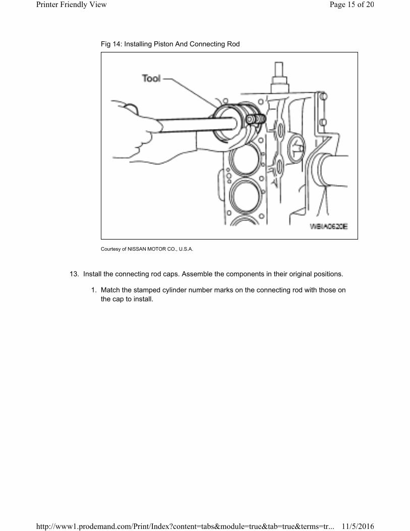
Fig 14: Installing Piston And Connecting Rod
Courtesy of NISSAN MOTOR CO., U.S.A.
13. Install the connecting rod caps. Assemble the components in their original positions.
1. Match the stamped cylinder number marks on the connecting rod with those on
the cap to install.
Page 15 of 20Printer Friendly View
11/5/2016http://www1.prodemand.com/Print/Index?content=tabs&module=true&tab=true&terms=tr...

Fig 15: Identifying Cylinder Number Marks On Connecting Rod
Courtesy of NISSAN MOTOR CO., U.S.A.
14. Tighten the connecting rod bolts using Tool in four steps as follows:
1. Apply engine oil to the threads and seats of the connecting rod bolts.
CAUTION: Always use either an angle wrench or protractor. Avoid
tightening based on visual check alone.
Step 1 : 27.4 N.m (2.8 kg-m, 20 lb-ft)
Step 2 : 0 N.m (0 kg-m, 0 lb-ft
Step 3 : 19.6 N.m (2.0 kg-m, 14 ft-lb)
Step 4 : 85° - 95° (target 90° degrees)
Page 16 of 20Printer Friendly View
11/5/2016http://www1.prodemand.com/Print/Index?content=tabs&module=true&tab=true&terms=tr...
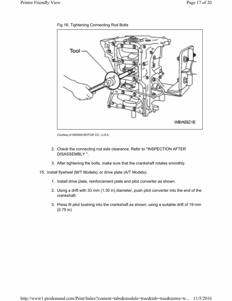
Fig 16: Tightening Connecting Rod Bolts
Courtesy of NISSAN MOTOR CO., U.S.A.
2. Check the connecting rod side clearance. Refer to "INSPECTION AFTER
DISASSEMBLY ".
3. After tightening the bolts, make sure that the crankshaft rotates smoothly.
15. Install flywheel (M/T Models), or drive plate (A/T Models).
1. Install drive plate, reinforcement plate and pilot converter as shown.
2. Using a drift with 33 mm (1.30 in) diameter, push pilot converter into the end of the
crankshaft.
3. Press fit pilot bushing into the crankshaft as shown; using a suitable drift of 19 mm
(0.75 in)
Page 17 of 20Printer Friendly View
11/5/2016http://www1.prodemand.com/Print/Index?content=tabs&module=true&tab=true&terms=tr...

Fig 17: Identifying Crankshaft Rear End
Courtesy of NISSAN MOTOR CO., U.S.A.
16. Install the cylinder block heater.
Cylinder block heater : 73.5 N.m (7.5 kg-m, 54 ft-lb)
17. Install the knock sensor.
1. Make sure that there is no foreign material on the cylinder block mating surface
and the back surface of the knock sensor.
2. Install the knock sensor with the connector facing lower left by 45° as shown.
3. Do not tighten the knock sensor bolt while holding the connector.
4. Make sure that the knock sensor does not interfere with other components.
Page 18 of 20Printer Friendly View
11/5/2016http://www1.prodemand.com/Print/Index?content=tabs&module=true&tab=true&terms=tr...

Fig 18: Identifying Knock Sensor
Courtesy of NISSAN MOTOR CO., U.S.A.
Knock sensor bolt : 21.1 N.m (2.2 kg-m, 16 ft-lb)
CAUTION: If the knock sensor is dropped, replace it with new one.
18. Install the crankshaft position sensor (POS).
Crankshaft position sensor bolt : 7.0 N.m (0.71 kg-m, 62 in-lb)
19. Installation of remaining components is in reverse order of removal.
SERVICE DATA AND SPECIFICATIONS (SDS) > SERVICE DATA AND
SPECIFICATIONS (SDS) > STANDARD AND LIMIT > GENERAL
SPECIFICATIONS
GENERAL SPECIFICATIONS CHART
Cylinder arrangement In-line 4
Displacement cm (cu in) 2,488 (151.82)
Bore and stroke mm (in)
3
Page 19 of 20Printer Friendly View
11/5/2016http://www1.prodemand.com/Print/Index?content=tabs&module=true&tab=true&terms=tr...

89.0 x 100.0 (3.504 x
3.937)
Valve arrangement DOHC
Firing order 1-3-4-2
Number of piston ringsCompression 2
Oil 1
Compression ratio 9.5
Compression pressure kPa (kg/cm ,
psi)/250 rpm
Standard 1,304 (13.3, 189)
Minimum 1,108 (11.3, 161)
Differential limit between
cylinders100 (1.0, 14)
2
Page 20 of 20Printer Friendly View
11/5/2016http://www1.prodemand.com/Print/Index?content=tabs&module=true&tab=true&terms=tr...