Embed Size (px)
Citation preview
1
ON THE SELF-WEIGHT SAG OF PLATE-LIKE STRUCTURES
WITH APPLICATION TO MIRROR SUBSTRATE DESIGN
by
DIPAK CHANDRA TALAPATRA
B. Tech. (Hons.), Indian Ins t i t u t e of Technology, Kharagpur, 196 3
M.E. McGill University, 1968
A THESIS SUBMITTED IN PARTIAL FULFILMENT OF
THE REQUIREMENTS FOR THE DEGREE OF
DOCTOR OF PHILOSOPHY
in the Department
of
MECHANICAL ENGINEERING
We accept t h i s thesis as conforming to the
required standard
THE UNIVERSITY OF BRITISH COLUMBIA
May, 19 72

In p r e s e n t i n g t h i s t h e s i s i n p a r t i a l f u l f i l m e n t o f the
requ i rements f o r an advanced degree a t the U n i v e r s i t y o f
B r i t i s h Co lumbia , I agree t h a t the L i b r a r y s h a l l make
i t f r e e l y a v a i l a b l e f o r r e f e r e n c e and s t u d y . I f u r t h e r
agree t h a t p e r m i s s i o n f o r e x t e n s i v e c o p y i n g o f t h i s t h e s i s
f o r s c h o l a r l y purposes may be g r a n t e d by the Head o f my
Department or by h i s r e p r e s e n t a t i v e s . I t i s unders tood
t h a t p u b l i c a t i o n , i n p a r t o r i n who le , o r the c o p y i n g o f
t h i s t h e s i s f o r f i n a n c i a l g a i n s h a l l no t be a l l owed w i t h
out my w r i t t e n p e r m i s s i o n .
DIPAK CHANDRA TALAPATRA
Department o f M e c h a n i c a l E n g i n e e r i n g
The U n i v e r s i t y o f B r i t i s h Columbia
Vancouver 8 , Canada
Date ^ ^ - ^ 7 , n 7 'Z-
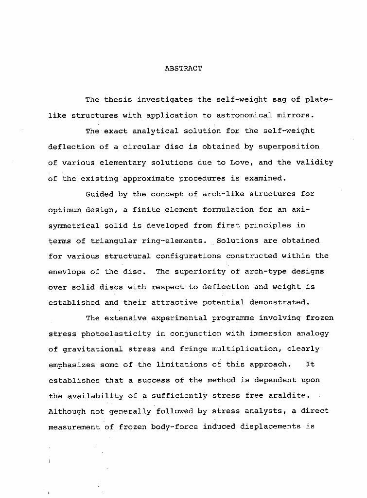
ABSTRACT
The t h e s i s i n v e s t i g a t e s the s e l f - w e i g h t sag o f p l a t e
l i k e s t r u c t u r e s w i t h a p p l i c a t i o n to a s t r o n o m i c a l m i r r o r s .
The e x a c t a n a l y t i c a l s o l u t i o n f o r the s e l f - w e i g h t
d e f l e c t i o n o f a c i r c u l a r d i s c i s o b t a i n e d by s u p e r p o s i t i o n
o f v a r i o u s e lementary s o l u t i o n s due to L o v e , and the v a l i d i t y
o f the e x i s t i n g approximate p rocedures i s examined.
Gu ided by the concept o f a r c h - l i k e s t r u c t u r e s f o r
optimum d e s i g n , a f i n i t e e lement f o r m u l a t i o n f o r an a x i -
symmetr i ca l s o l i d i s deve loped from f i r s t p r i n c i p l e s i n
terms o f t r i a n g u l a r r i n g - e l e m e n t s . S o l u t i o n s a re o b t a i n e d
f o r v a r i o u s s t r u c t u r a l c o n f i g u r a t i o n s c o n s t r u c t e d w i t h i n the
enev lope o f the d i s c . The s u p e r i o r i t y o f a r c h - t y p e d e s i g n s
over s o l i d d i s c s w i t h r e s p e c t t o d e f l e c t i o n and we ight i s
e s t a b l i s h e d and t h e i r a t t r a c t i v e p o t e n t i a l demonst ra ted .
The e x t e n s i v e e x p e r i m e n t a l programme i n v o l v i n g f r o z e n
s t r e s s p h o t o e l a s t i c i t y i n c o n j u n c t i o n w i t h immersion ana logy
o f g r a v i t a t i o n a l s t r e s s and f r i n g e m u l t i p l i c a t i o n , c l e a r l y
emphasizes some o f the l i m i t a t i o n s o f t h i s a p p r o a c h . I t
e s t a b l i s h e s t h a t a success o f the method i s dependent upon
the a v a i l a b i l i t y o f a s u f f i c i e n t l y s t r e s s f r e e a r a l d i t e .
A l t h o u g h not g e n e r a l l y f o l l o w e d by s t r e s s a n a l y s t s , a d i r e c t
measurement o f f r o z e n b o d y - f o r c e induced d i s p l a c e m e n t s i s

attempted. The phenomenon of continuous polymerization of
the model material, hitherto overlooked by photoelasticians,
appears to play a decisive role i n the measurement of
minute self-weight induced deformations.
The d i r e c t use of s i l i c o n e rubber models successfully
determines the displacements i n mirrors, i n the form of
s o l i d disc and arched dome, and establishes the su p e r i o r i t y
of the l a t t e r .
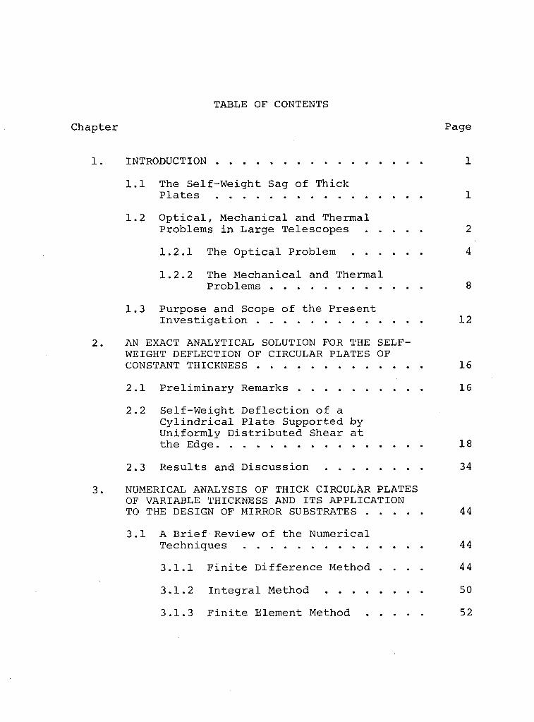
T A B L E O F C O N T E N T S
C h a p t e r P a g e
1. I N T R O D U C T I O N 1
1.1 T h e S e l f - W e i g h t S a g o f T h i c k P l a t e s 1
1.2 O p t i c a l , M e c h a n i c a l a n d T h e r m a l
P r o b l e m s i n L a r g e T e l e s c o p e s 2
1.2.1 T h e O p t i c a l P r o b l e m 4
1.2.2 T h e M e c h a n i c a l a n d T h e r m a l
P r o b l e m s . 8 1.3 P u r p o s e a n d S c o p e o f t h e P r e s e n t
I n v e s t i g a t i o n 12
2. A N E X A C T A N A L Y T I C A L S O L U T I O N F O R T H E S E L F -W E I G H T D E F L E C T I O N O F C I R C U L A R P L A T E S O F C O N S T A N T T H I C K N E S S 16
2.1 P r e l i m i n a r y R e m a r k s 16
2.2 S e l f - W e i g h t D e f l e c t i o n o f a C y l i n d r i c a l P l a t e S u p p o r t e d b y U n i f o r m l y D i s t r i b u t e d S h e a r a t t h e E d g e 18
2.3 R e s u l t s a n d D i s c u s s i o n 34
3. N U M E R I C A L A N A L Y S I S OF T H I C K C I R C U L A R P L A T E S OF V A R I A B L E T H I C K N E S S AND I T S A P P L I C A T I O N T O T H E D E S I G N OF M IRROR S U B S T R A T E S 44
3.1 A B r i e f R e v i e w o f t h e N u m e r i c a l T e c h n i q u e s 44
3.1.1 F i n i t e D i f f e r e n c e M e t h o d . . . . 44
3.1.2 I n t e g r a l M e t h o d 50
3.1.3 F i n i t e E l e m e n t M e t h o d 52
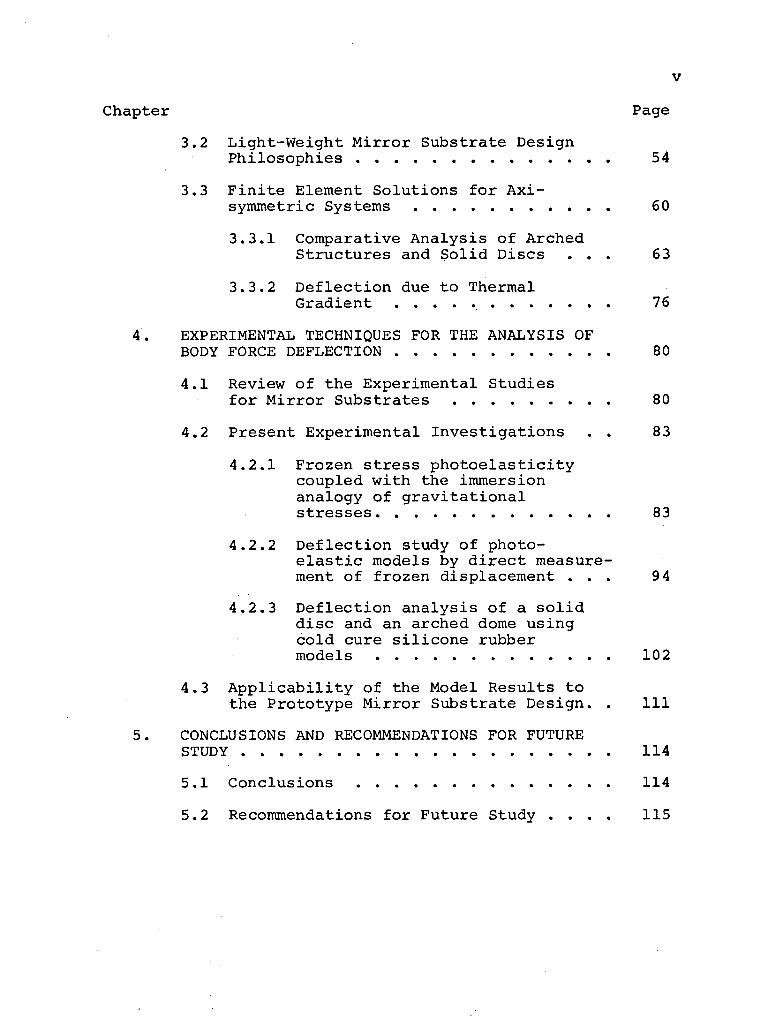
V
Chapter Page
3.2 Light-Weight Mirror Substrate Design Philosophies 54
3.3 F i n i t e Element Solutions for Axi-symmetric Systems 60
3. 3 . 1 Comparative Analysis of Arched Structures and S o l i d Discs . . . 6 3
3.3.2 Deflection due to Thermal Gradient 76
4. EXPERIMENTAL TECHNIQUES FOR THE ANALYSIS OF BODY FORCE DEFLECTION 80
4.1 Review of the Experimental Studies for Mirror Substrates 80
4.2 Present Experimental Investigations . . 83
4 . 2 . 1 Frozen stress p h o t o e l a s t i c i t y coupled with the immersion analogy of g r a v i t a t i o n a l stresses 83
4.2.2 Deflection study of photo-e l a s t i c models by d i r e c t measurement of frozen displacement . . . 94
4 . 2 . 3 Deflection analysis of a s o l i d disc and an arched dome using cold cure s i l i c o n e rubber models 1 0 2
4.3 A p p l i c a b i l i t y of the Model Results to the Prototype Mirror Substrate Design. . I l l
5. CONCLUSIONS AND RECOMMENDATIONS FOR FUTURE STUDY 1 1 4
5.1 Conclusions 1 1 4
5.2 Recommendations for Future Study . . . . 1 1 5
v i
Chapter Page
REFERENCES 120
APPENDIX 1 - F i n i t e E lement A n a l y s i s o f A x i -symmetric Body F o r c e - L o a d e d S o l i d s 1-1
APPENDIX 2 - E v a l u a t i o n o f De format ions Due to Thermal E f f e c t s 2-1
LIST OF TABLES
T a b l e Page
3.1 F i g u r e o f M e r i t Va lues 73

LIST OF FIGURES
Figure Page
1.1 Formation of Images from Distant Stars . . . . 6
1.2 Cusp-Like Surface Formed by Oblique Rays 7
1.3 Possible Ways of Supporting a Mirror • Substrate . . . . . 9
1.4 The 200-inch Hale Telescope Mirror Support Mechanism 9
1.5 Table of Substrate Forms 15
2.1 Superposition of Several Elementary Solutions 20
2.2 Notations for C y l i n d r i c a l Plate 22
2.3 Total Body Force Considered Equivalent to an Equal Uniformly Distributed Surface Pressure, q = 2pgh 35
2.4 D i s t r i b u t i o n of Radial and Shear Stresses at the End of the Plate 35
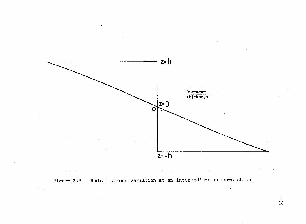
2.5 Radial Stress Variation at an Intermediate Cross-Section 36
2.6 A x i a l Stress D i s t r i b u t i o n 37
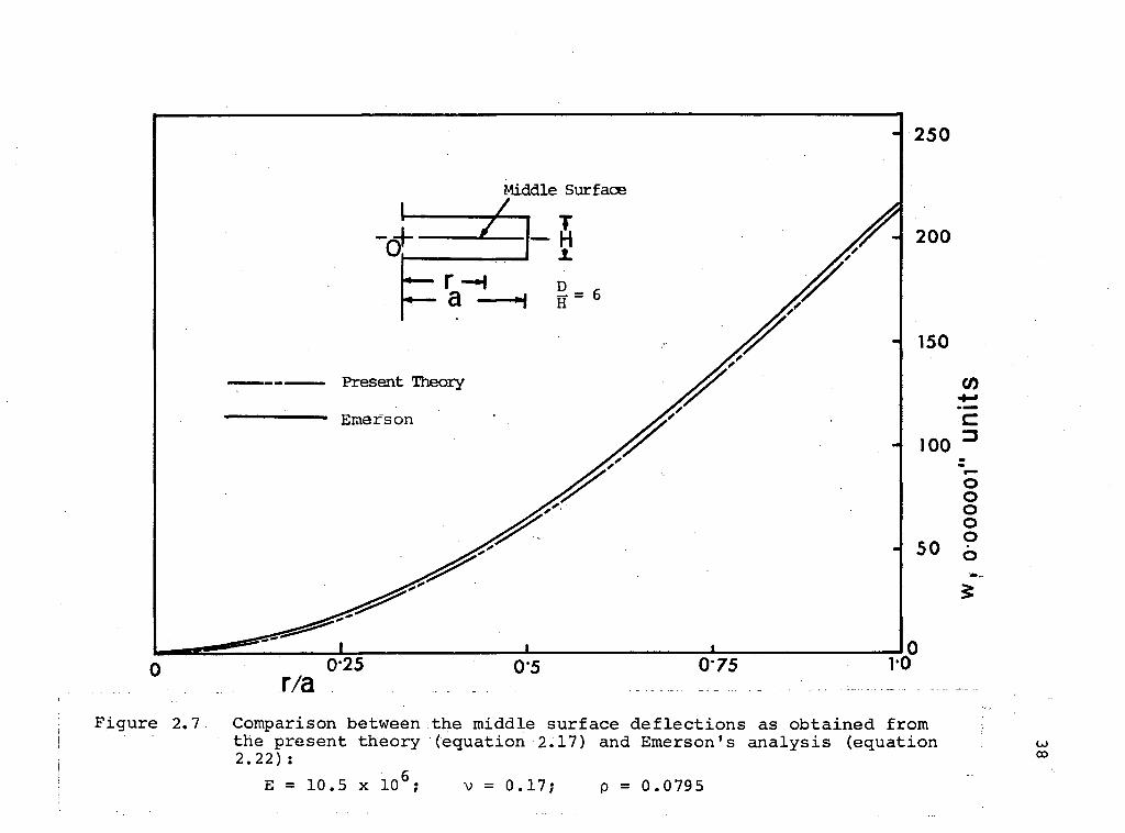
2.7 Comparison between Middle Surface Deflections as Obtained from the Present Theory (Equation !
2.17) and Emerson's Analysis (Equation 2.22) . 38
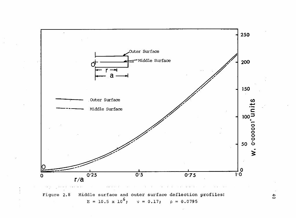
2.8 Middle and Outer Surface Deflection P r o f i l e s . 40
2.9 A Comparison Between the Present Analysis and the Thin Plate Theory Results for Several D/H Ratios 42
3.1 Axisymmetric S o l i d 45
3.2 A x i a l z-r Plane 45
i x
F i g u r e Page
3.3 Sandwich and C e l l u l a r M i r r o r S u b s t r a t e s . . . 56
3.4 C a s t e l l a t e d Beam 58
3.5 M i c h e l 1 S t r u c t u r e 58
3.6 The M i d d l e S u r f a c e D e f l e c t i o n s as P r e d i c t e d by the F i n i t e E lement Procedure and the A n a l y t i c a l S o l u t i o n 61
3.7 E f f e c t o f Support C i r c l e Radius on the M i d d l e S u r f a c e D e f l e c t i o n 62
3.8 A rched S t r u c t u r e s C o n s t r u c t e d w i t h i n the Space Enve lope o f the S o l i d D i s c o f D/H =6 65
3.9 Compar ison o f the Upper S u r f a c e D e f l e c t i o n s f o r S o l i d D i s c (1) w i t h t h a t o f A r c h Models (1) and (2)
(a) L a t e r a l D e f l e c t i o n 66 (b) R a d i a l D e f l e c t i o n 67
3.10 Upper S u r f a c e D e f l e c t i o n s f o r S o l i d D i s c (2) and A rch Model (3) 68
3.11 Comparison o f the Upper S u r f a c e D e f l e c t i o n s o f A r c h Models (1) and (2) as R a t i o s o f the D e f l e c t i o n o f S o l i d D i s c (1)
(a) L a t e r a l D e f l e c t i o n 69 (b) R a d i a l D e f l e c t i o n 70
3.12 Upper S u r f a c e D e f l e c t i o n s o f A r c h Model (3) as R a t i o s o f the D e f l e c t i o n o f S o l i d D i s c (2) 71
3.13 Top S u r f a c e D e f l e c t i o n o f a C a s s e g r a i n i a n S u b s t r a t e as a F u n c t i o n o f Support C i r c l e Radius 75
3.14 E f f e c t o f Temperature G r a d i e n t T = 2z on A x i a l D e f l e c t i o n o f a T h i c k C y l i n d r i c a l P l a t e , D/H = 6 77
X
F i g u r e Page
3.15 R a d i a l D e f l e c t i o n i n a T h i c k C y l i n d r i c a l P l a t e Due t o Temperature G r a d i e n t T = 2z 78
4.1 Immersion Ana logy f o r G r a v i t a t i o n a l S t r e s s e s 85
4.2 Schemat ic Diagram Showing Model i n Oven, Mercury Vapour Condensat ion T e c h n i q u e , and the L o c a t i o n s o f S l i c e s Taken f o r Examina t ion 87
4.3 L i g h t R e f l e c t i o n and T r a n s m i s s i o n Between Two S l i g h t l y I n c l i n e d P a r t i a l M i r r o r s 89
4.4 P a r t i a l M i r r o r s as Employed i n P o l a r i -scope f o r F r i n g e M u l t i p l i c a t i o n 89
4.5 M u l t i p l i e d F r i n g e P a t t e r n s f o r a R a d i a l S l i c e Through a Support P o i n t 90
4.6 M u l t i p l i e d F r i n g e P a t t e r n s f o r a S e c t o r S l i c e Through Two Support P o i n t s . . . . . 91
4.7 F r i n g e Photograph f o r the R ing Suppor ted S o l i d D i s c
(a) Normal Load ing 97 (b) Reverse L o a d i n g 97
4.8 S e l f - W e i g h t D e f l e c t i o n o f the R ing Supported S o l i d D i s c 98
4.9 F r i n g e Photograph f o r the S imply Supported Beam
(a) Normal L o a d i n g 99 (b) Reverse L o a d i n g 99
4.10 S e l f - W e i g h t D e f l e c t i o n o f the S imply Suppor ted Beam 100
4.11 Fo rmat ion o f Shadow Mo i re F r i n g e s 104

x i
F i g u r e Page
4.12 Support Frames f o r Models 106
4.13 Shadow Mo i re F r i n g e , P a t t e r n s f o r the S o l i d D i s c
(a) Model i n G l y c e r i n e 108 (b) Model i n A i r 108
4.14 Shadow Moi re F r i n g e P a t t e r n s f o r the Arched Model
(a) Model i n G l y c e r i n e 109 (b) Model i n A i r 109
4.15 Comparison o f G r a v i t y - I n d u c e d Upper S u r f a c e w D e f l e c t i o n s f o r the S o l i d D i s c With That o f the Arch Model 110
4.16 V a r i a t i o n o f Top S u r f a c e a w i t h P o i s s o n ' s R a t i o . . 112
5.1 A rched S u b s t r a t e Form f o r T h r e e - P o i n t Supports 117
5.2 A rched S u b s t r a t e Form w i t h R a d i a l and C i r c u m f e r e n t i a l Grooves 118
A l . l F i n i t e E lement I d e a l i s a t i o n o f A x i -symmetr ic S o l i d
(a) A c t u a l Continuum 1~2 (b) T r i a n g u l a r E lement A p p r o x i
mat ion 1-2
A1.2 Nodal C o o r d i n a t e s and D isp lacement Components 1-3

ACKNOWLEDGEMENT
The author wishes to express h i s i ndebtedness t o
D r . J . P . Duncan f o r h i s v a l u a b l e gu idance and c r i t i c i s m s
throughout the s tudy and p r e p a r a t i o n o f the t h e s i s . Thanks
are a l s o due t o D r . V . J . Modi f o r h i s h e l p and c o n s t r u c t i v e
s u g g e s t i o n s i n the p r e p a r a t i o n o f the f i n a l m a n u s c r i p t .
The s u g g e s t i o n s by D r . H. Vaughan and D r . D. Pos t
a re d u l y a p p r e c i a t e d .
The au thor would a l s o l i k e to thank Mr. John Hoar ,
C h i e f T e c h n i c i a n , and h i s s t a f f f o r t h e i r h e l p i n the
e x p e r i m e n t a l work.
The p r o j e c t was suppor ted by the N a t i o n a l Research
C o u n c i l , Grant No. 67-3309.
LIST OF SYMBOLS
d i a m e t e r , 2a; modulus o f r i g i d i t y
e l a s t i c i t y m a t r i x f o r i s o t r o p i c m a t e r i a l
Young 1 s modulus
e x t e r n a l n o d a l f o r c e
n o d a l f o r c e due t o body f o r c e
n o d a l f o r c e due to t h e r m a l e f f e c t
body f o r c e i n t e n s i t y i n the z d i r e c t i o n
t h i c k n e s s , 2h
s t i f f n e s s m a t r i x
suppor t c i r c l e r a d i u s / r a d i u s o f the p l a t e
average temperature r i s e i n an e lement
d i s p l a c e m e n t f u n c t i o n
a c c e l e r a t i o n due to g r a v i t y
body f o r c e v e c t o r
i n t e n s i t y o f a c o n t i n u o u s l y d i s t r i b u t e d l o a d
t ime
d i s p l a c e m e n t s i n x , y , z d i r e c t i o n s
mid-p lane d i s p l a c e m e n t
r e c t a n g u l a r c o o r d i n a t e s
c y l i n d r i c a l c o o r d i n a t e s

c o e f f i c i e n t of thermal expansion
shear s t r a i n component i n c y l i n d r i c a l coordinates
element nodal displacement
area of the tr i a n g l e
normal s t r a i n components i n c y l i n d r i c a l coordinates
s t r a i n vector
thermal s t r a i n vector
wave length of l i g h t
Poisson's r a t i o
density
normal stress components i n c y l i n d r i c a l coordinates
stress vector
shear stress component i n c y l i n d r i c a l coordinates
stress function

1. INTRODUCTION
1.1 The S e l f - W e i g h t Sag o f T h i c k P l a t e s
T h i s i n v e s t i g a t i o n i s p r i m a r i l y concerned w i t h
d e v e l o p i n g and a p p l y i n g methods f o r p r e d i c t i n g the s e l f -
we ight sag o f t h i c k p l a t e s . The i n v e s t i g a t i o n was
prompted by s e v e r a l problems a r i s i n g i n l a r g e m i r r o r
s u b s t r a t e d e s i g n and i t i s i n t h i s a rea t h a t the methods
have been u s e d . T r a d i t i o n a l l y , an a s t r o n o m i c a l m i r r o r ,
l a r g e o r s m a l l , i s d e s i g n e d as a r i g h t c y l i n d r i c a l d i s c
h a v i n g a d iameter to t h i c k n e s s r a t i o o f 8 to 1 (smal l
a p e r t u r e ) o r 6 to 1 ( l a r g e a p e r t u r e ) . These r a t i o s a re
r u l e s o f thumb proposed by R i t c h e y [1] on the b a s i s o f
e x p e r i e n c e . The s m a l l e r r a t i o , recommended f o r l a r g e
m i r r o r s , r e f l e c t s the importance o f s e l f - w e i g h t d e f l e c t i o n ,
4 2 which i s p r o p o r t i o n a l t o (Radius) / ( T h i c k n e s s ) f o r a
m i r r o r u n i f o r m l y suppor ted a t i t s p e r i p h e r y . I t i s
apparent t h a t , w i t h such s m a l l d iameter to t h i c k n e s s r a t i o s ,
a t h e o r e t i c a l i n v e s t i g a t i o n cannot be accomp l i shed by
u s i n g c o n v e n t i o n a l t h i n p l a t e t h e o r y . I t i s n e c e s s a r y to
t r e a t the m i r r o r , as a t h i c k p l a t e , t h a t i s , an a x i s y m m e t r i c
body governed by the t h r e e - d i m e n s i o n a l f i e l d equa t ions o f
e l a s t i c i t y .

2
I n m a n y i n s t a n c e s , t h e m i r r o r m a y b e s l i g h t l y c u r v e d
f o r r e a s o n s o f o p t i c a l s u r f a c e f o r m ( p a r a b o l i c ) a n d a r c h e d
f o r w e i g h t e c o n o m y . T h e p o i n t s e r v e s t o i n d i c a t e t h e
n e c e s s i t y o f a n a l y z i n g a x i s y m m e t r i c t h i c k p l a t e s o f
v a r i a b l e t h i c k n e s s , t h a t i s , s h a l l o w d o m e s o r a x i s y m m e t r i c
s h a l l o w a r c h e d s t r u c t u r e s .
I n t h i n p l a t e t h e o r y , a c o m m o n t e c h n i q u e f o r e x a m i n
i n g b o d y f o r c e e f f e c t s i s t o r e p l a c e i t b y a n e q u i v a l e n t
s u r f a c e l o a d . T h i s s i m p l i f y i n g t e c h n i q u e c a n n o t b e u s e d
f o r t h i c k p l a t e s a n d i t i s n e c e s s a r y t o a c c o u n t f o r g r a v i t y
d e f o r m a t i o n . A p a r t f r o m t h e d e s i r a b l e f e a t u r e o f r e l i a b i l i t y
o f t h e p r o c e d u r e , t h e i n c l u s i o n o f b o d y f o r c e s i n t h e t h e o r y
a u t o m a t i c a l l y s u p p l i e s a s o l u t i o n f o r t h e r m a l e f f e c t s . I t
i s o n l y n e c e s s a r y t o i n t e r p r e t t h e b o d y f o r c e s t r e s s e s
a p p r o p r i a t e l y a n d b y t h e m e t h o d o f s t r a i n s u p p r e s s i o n i n
t h e r m o e l a s t i c i t y , t h e r e s u l t s a p p l y t o t h e r m a l e f f e c t s . T h e
e f f e c t s o f t h e r m a l s t r e s s e s i n a s t r o n o m i c a l m i r r o r o p e r a t i o n
i s o f p a r a m o u n t i n t e r e s t a n d a n y i n f o r m a t i o n o b t a i n a b l e f r o m
t h e p r e s e n t i n v e s t i g a t i o n may b e c o n s i d e r e d u s e f u l .
1 . 2 O p t i c a l , M e c h a n i c a l a n d T h e r m a l P r o b l e m s i n L a r g e T e l e s c o p e s
A n a s t r o n o m i c a l t e l e s c o p e m i r r o r i s b a s i c a l l y a
s p e c u l a r , r e f l e c t i v e s u r f a c e w h o s e g e o m e t r i c a l f o r m i s
m a i n t a i n e d b y a n u n d e r l y i n g s u p p o r t i n g s t r u c t u r e o r
3
s u b s t r a t e . I f the s u b s t r a t e s e r v e s by i t s mere e x i s t e n c e
as a " c r e a t o r " o f a s u r f a c e o r i n t e r f a c e , i t s e lements
become masses which a re d i s t r i b u t e d i n space and thus a re
s u b j e c t e d t o g r a v i t a t i o n a l a t t r a c t i o n .
; The m i r r o r s u r f a c e would change i t s shape i f the
p h y s i c a l s t a t e o f the s u b s t r a t e a l t e r s . T h i s may a r i s e
when the o r i e n t a t i o n o f the m i r r o r o r the g r a v i t a t i o n a l
f i e l d changes . A change i n geometry o f the e l a s t i c s t r u c t u r e
can a l s o be induced by v a r i a t i o n s i n a b s o l u t e t empera tu re ;
o r by the e x i s t e n c e o f temperature g r a d i e n t s . F u r t h e r m o r e ,
problems o f d i m e n s i o n a l s t a b i l i t y may a r i s e from r e l a x a t i o n
o f r e s i d u a l s t r e s s e s i n t r o d u c e d d u r i n g p r o c e s s i n g .
F o r s a t i s f a c t o r y per formance o f the m i r r o r , the
s u b s t r a t e has to be so d e s i g n e d t h a t the geomet r i c form o f
the r e f l e c t i v e s u r f a c e i s m a i n t a i n e d w i t h i n an a c c e p t a b l e
l i m i t de te rmined by d i f f r a c t i o n o p t i c s . The c u r r e n t g e n e r a l
p h i l o s o p h y o f m i r r o r suppor t i s to e q u i l i b r a t e the we ight
o f each e lement o f the m i r r o r s u b s t r a t e as d i r e c t l y as
p o s s i b l e by v a r i o u s s u i t a b l y d e s i g n e d mechanisms. Thus
the e l a s t i c de fo rmat ions o f the s u b s t r a t e , which occur as
the m i r r o r i s o r i e n t e d i n d i f f e r e n t p o s i t i o n s , are
m i n i m i z e d .
4
These complex mechanisms a re q u i t e e l a b o r a t e .
I n s t e a d o f d e s i g n i n g the s u b s t r a t e as a mass ive s t r u c t u r e
w i t h many s u p p o r t s , a l t e r n a t i v e forms o f compos i te and
b u i l t - u p s u b s t r a t e s have been des igned and c o n s t r u c t e d .
Here the aim i s t o deve lop h i g h s t i f f n e s s - t o - w e i g h t r a t i o
s t r u c t u r e s w i t h a c a p a b i l i t y o f r e s i s t i n g changes i n
shape by an a c c e p t a b l e degree o f f l e x u r e . These l i g h t
we igh t m i r r o r d e s i g n s can be o b t a i n e d by chang ing the
c o n v e n t i o n a l g e o m e t r i c a l forms o f the s u b s t r a t e through
r e d i s t r i b u t i o n o f m a t e r i a l . As an a l t e r n a t i v e to
u s i n g many c l o s e l y spaced s u p p o r t mechanisms, ment ioned
above, l i g h t - w e i g h t s u b s t r a t e s may be suppor ted d i r e c t l y
a t t h r e e p o i n t s o r a t s i x i n t e r n a l p o i n t s on a l i m i t e d
system o f b a l a n c e d l e v e r s p i v o t e d a t t h r e e p r imary p o i n t s
on the frame o f r e f e r e n c e .
1.2.1 The O p t i c a l Problem
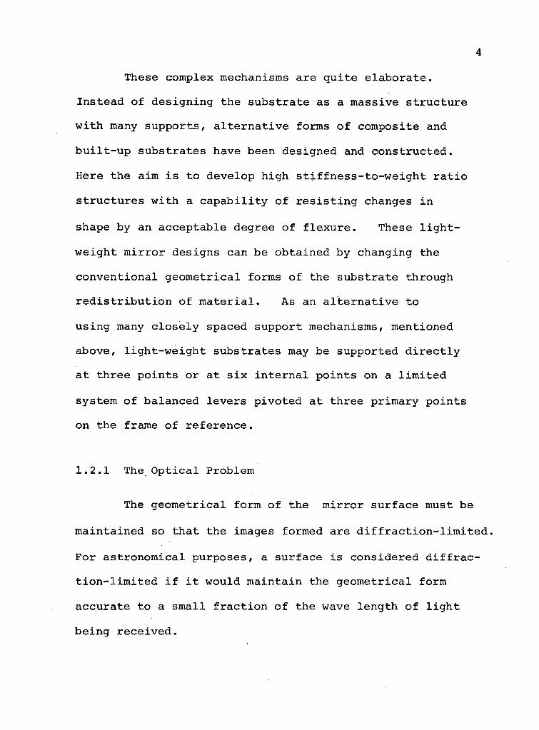
The g e o m e t r i c a l form o f the m i r r o r s u r f a c e must be
m a i n t a i n e d so t h a t the images formed are d i f f r a c t i o n - l i m i t e d .
F o r a s t r o n o m i c a l p u r p o s e s , a s u r f a c e i s c o n s i d e r e d d i f f r a c
t i o n - l i m i t e d i f i t would m a i n t a i n the g e o m e t r i c a l form
a c c u r a t e to a s m a l l f r a c t i o n o f the wave l e n g t h o f l i g h t
b e i n g r e c e i v e d .

5
Rays coming from d i s t a n t s t a r s form images as
shown i n F i g u r e 1.1. Due to d i f f r a c t i o n e f f e c t s the images,
i n s t e a d o f b e i n g p o i n t s , would c o n s i s t o f b r i g h t c e n t r a l
A i r y ' s d i s c s surrounded by a l t e r n a t e dark and b r i g h t r i n g s .
A p a r a b o l i c r e f l e c t i n g s u r f a c e g i v e s a t h e o r e t i c a l l y
i d e a l f o c u s s i n g b u t , even w i t h a p e r f e c t geometry , t h e r e i s
a lower l i m i t t o the ang le of s e p a r a t i o n between two o b j e c t s ,
1 22X
a = _ i _ — f where D = d iameter of the a p e r t u r e and X = wave
l e n g t h o f the l i g h t . T h i s e x p r e s s i o n i s determined from
R a y l e i g h ' s c r i t e r i o n which s t a t e s t h a t two images may
be r e s o l v e d when the c e n t r a l maximum o f one f a l l s ove r the
f i r s t minimum of the o t h e r . As i n d i c a t e d by the above
f o r m u l a t h i s l i m i t f o r a depends on D. In o r d e r t o make a
s m a l l , D has t o be l a r g e . Any i m p e r f e c t i o n o f the r e f l e c t
i n g s u r f a c e degrades t h i s l i m i t which i s r e a l l y f i x e d by
X s i n c e we cannot c o n t r o l the wave l e n g t h o f l i g h t .
A p a r a b o l i c m i r r o r f o c u s e s a t a nomina l p o i n t ,
c a l l e d the " f o c u s " o n l y f o r p r i n c i p a l r a y s . Ob l i que r a y s
focus on a c u s p - l i k e s u r f a c e (F igure 1.2). Hence, r e a l
m i r r o r s u r f a c e s are not always formed as t r u e p a r a b o l o i d s .
They are c o r r e c t e d to e f f e c t some g e o m e t r i c a l c o n t r o l o f
f o c u s s i n g i n a f o c a l p l a n e .

M i r r o r
D
| F i g u r e 1.1 Format ion o f images from d i s t a n t s t a r s
i

7
C u s p - L i k e Sur face
F o c a l P lane
— — —— P r i n c i p a l Rays
•Obl ique Rays
Figure 1.2 C u s p - l i k e surface formed by oblique rays
8
1.2.2 The M e c h a n i c a l and Thermal Problems
To m a i n t a i n a s p e c i f i e d s u r f a c e fo rm,an u n d e r l y i n g
s u b s t r a t e , on which the s u r f a c e i s formed, i s r e q u i r e d .
D u r i n g o b s e r v a t i o n s , a m i r r o r may be r o t a t e d i n t o
d i f f e r e n t a t t i t u d e s i n the g r a v i t a t i o n a l f i e l d . I f the
m i r r o r s u r f a c e i s des igned t o be a c c u r a t e when s u p p o r t e d i n
a h o r i z o n t a l p o s i t i o n , the s u r f a c e shape may change as the
m i r r o r i s moved i n t o d i f f e r e n t a t t i t u d e s . Hence a ' r i g i d '
s u b s t r a t e must be s t i f f enough t o ensure t h a t a t t e n d a n t
e l a s t i c d i s t o r t i o n s are l e s s than a c c e p t a b l e amounts.
There are a t l e a s t two p o s s i b l e ways o f s u p p o r t i n g
a m i r r o r s u b s t r a t e :
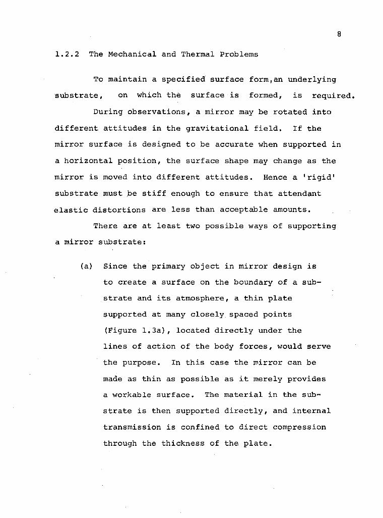
(a) S i n c e the pr imary o b j e c t i n m i r r o r d e s i g n i s
t o c r e a t e a s u r f a c e on the boundary o f a s u b
s t r a t e and i t s atmosphere , a t h i n p l a t e
suppor ted at many c l o s e l y spaced p o i n t s
(F igure 1.3a), l o c a t e d d i r e c t l y under the
l i n e s o f a c t i o n o f the body f o r c e s , would s e r v e
the p u r p o s e . In t h i s case the m i r r o r can be
made as t h i n as p o s s i b l e as i t mere ly p r o v i d e s
a workable s u r f a c e . The m a t e r i a l i n the sub
s t r a t e i s then suppor ted d i r e c t l y , and i n t e r n a l
t r a n s m i s s i o n i s c o n f i n e d to d i r e c t compress ion
through the t h i c k n e s s o f the p l a t e .

/7 7 77 7 777777J7 Foundat ion
a . T h i n P l a t e
/ / / / / / / / / / Foundat ion
b. T h i c k P l a t e
F i g u r e 1.3 P o s s i b l e ways of s u p p o r t i n g
a m i r r o r s u b s t r a t e F i g u r e 1 . 4 The 2 0 0 - i n c h _H_ale t e l e s c o p e
m i r r o r suppor t :" mechanism
10
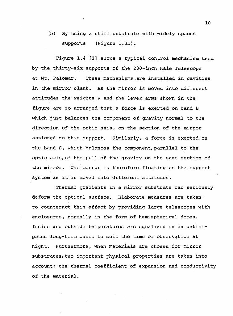
(b) By u s i n g a s t i f f s u b s t r a t e w i t h w i d e l y spaced
s u p p o r t s (F igure 1 . 3 b ) .
F i g u r e 1.4 [2] shows a t y p i c a l c o n t r o l mechanism used
by the t h i r t y - s i x suppor ts o f the 2 0 0 - i n c h Hale T e l e s c o p e
a t Mt . Pa lomar . These mechanisms are i n s t a l l e d i n c a v i t i e s
i n the m i r r o r b l a n k . As the m i r r o r i s moved i n t o d i f f e r e n t
a t t i t u d e s the we ights W and the l e v e r arms shown i n the
f i g u r e are so a r ranged t h a t a f o r c e i s e x e r t e d on band B
which j u s t b a l a n c e s the component o f g r a v i t y normal to the
d i r e c t i o n o f the o p t i c a x i s , on the s e c t i o n o f the m i r r o r
a s s i g n e d to t h i s s u p p o r t . S i m i l a r l y , a f o r c e i s e x e r t e d on
the band S, which b a l a n c e s the component, p a r a l l e l t o the
o p t i c a x i s , o f the p u l l o f the g r a v i t y on the same s e c t i o n o f
the m i r r o r . The m i r r o r i s t h e r e f o r e f l o a t i n g on the suppor t
system as i t i s moved i n t o d i f f e r e n t a t t i t u d e s .
Thermal g r a d i e n t s i n a m i r r o r s u b s t r a t e can s e r i o u s l y
deform the o p t i c a l s u r f a c e . E l a b o r a t e measures are taken
to c o u n t e r a c t t h i s e f f e c t by p r o v i d i n g l a r g e t e l e s c o p e s w i t h
e n c l o s u r e s , n o r m a l l y i n the form o f h e m i s p h e r i c a l domes.
I n s i d e and o u t s i d e temperatures are e q u a l i z e d on an a n t i c i
pa ted l o n g - t e r m b a s i s t o s u i t the t ime o f o b s e r v a t i o n a t
n i g h t . F u r t h e r m o r e , when m a t e r i a l s are chosen f o r m i r r o r
subs t ra tes* two impor tant p h y s i c a l p r o p e r t i e s a re taken i n t o
account ; the therma l c o e f f i c i e n t o f expans ion and c o n d u c t i v i t y
o f the m a t e r i a l .

11 E s s e n t i a l l y a m a t e r i a l w i t h a low c o e f f i c i e n t o f
expans ion i s sought s i n c e i t s ' o p t i c a l f i g u r e ' would be
s t a b l e under normal ambient temperature f l u c t u a t i o n s and i t
i s l e s s l i k e l y t o be s u s c e p t i b l e t o the rma l e f f e c t s . On
the o t h e r h a n d , h i g h t h e r m a l c o n d u c t i v i t y i s n e c e s s a r y , s i n c e
t h i s would enab le the m i r r o r t o r e a c h the rma l e q u i l i b r i u m
q u i c k l y , e s p e c i a l l y d u r i n g g r i n d i n g when i t i s n e c e s s a r y t o
d i s s i p a t e the hea t genera ted by f r i c t i o n . B e s i d e s e l e c t i n g
the m a t e r i a l f o r m i r r o r s u b s t r a t e s w i t h p r o p e r v a l u e s o f the
therma l c o e f f i c i e n t o f expans ion and t h e r m a l c o n d u c t i v i t y ,
i t s mounts must a l s o be s u i t a b l y d e s i g n e d so t h a t the therma l
d i s t o r t i o n i s m i n i m i z e d .
A l though s c a r c e , a r e f e r e n c e s h o u l d be made t o the
r e l e v a n t i n v e s t i g a t i o n s i n the f i e l d . D e f l e c t i o n a n a l y s i s o f
m i r r o r s u b s t r a t e was i n i t i a t e d by Couder (1931) [3]. He
i n v e s t i g a t e d f l a t c y l i n d r i c a l m i r r o r s by t a k i n g account o f
bend ing s t r e s s e s o n l y , the shear s t r e s s e s b e i n g n e g l e c t e d .
I t was conc luded from o b s e r v a t i o n s and an approximate a n a l y s i
t h a t the f l e x u r e o f v e r t i c a l l y mounted m i r r o r s would not be
d e t e c t a b l e up t o a d iameter o f about 120 i n c h e s . Schwesinger
(1954) [4] a n a l y z e d a v e r t i c a l l y mounted m i r r o r and took
e x c e p t i o n t o the c o n c l u s i o n o f Couder . More r e c e n t l y ,
M a l v i c k and Pearson (1968) [5] conducted d e f l e c t i o n
a n a l y s i s of C a s s e g r a i n i a n - t y p e m i r r o r s u b s t r a t e s w i t h
a s p h e r i c a l l y d i s h e d f r o n t s u r f a c e . They used the
n u m e r i c a l method o f 'dynamic r e l a x a t i o n ' t o s tudy
m i r r o r de fo rmat ions a t d i f f e r e n t a t t i t u d e s i n c o - o r d i n a t e
12
space. Kenny ( 1 9 6 8 ) [ 6 ] undertook elementary experimental
inves t i g a t i o n for c y l i n d r i c a l , arched and build-up arched
substrates and found the d e f l e c t i o n of the arched model
to be smaller than that of the equivalent r i g h t c y l i n d r i c a l
blank.
1.3 Purpose and Scope of the Present Investigation
The long established use of r i g h t c y l i n d r i c a l disc
as substrate for small aperture has led, by extension, to
the use of such s o l i d substrates even for large aperture
elements. For instance the ground-based r e f l e c t i o n
Telescope of K i t t Peak i s 1 5 6 inches i n diameter and 26
inches thick. This i s characterized by a t r a d i t i o n a l
aperture to thickness r a t i o of 6 to 1. A disc such as t h i s
s t i l l has to be supported at many discrete points by care
f u l l y calculated and controlled forces, arranged to balance
the g r a v i t a t i o n a l forces which tend to deform the substrate
as the mirror i s manoeuvred to occupy desired p o s i t i o n s .
Thus i t i s apparent that with ground based mirrors, 4 2
as the size increases, the a /H r e l a t i o n for constant
s t i f f n e s s leads to excessive substrate weight with attendant
problems of the support design. With space-borne telescopes
the reduction of substrate weight becomes even more
important. Questions such as t o t a l mass to be accelerated
i n space and changes i n the substrate shape as the telescope
13
i s taken from the one-g f i e l d to zero-g f i e l d have to be
considered. One promising solution to the two major problems
mentioned above i s to design substrates having the highest
possible stiffness-to-weight r a t i o .
The investigation reported here considers the s e l f -
weight sag of plates i n three fundamental ways. F i r s t l y , a
th e o r e t i c a l investigation has been conducted for thick >
plates of constant thickness. This method makes use of
some re s u l t s due to Love [ 7 ] for axisymmetric bodies.
Using his r e s u l t s , an exact a n a l y t i c a l solution has been
formulated for the self-weight sag of a thick plate supported
by uniform shear forces along the periphery. Although t h i s
exact solution i s primarily of academic i n t e r e s t i t provides
an excellent check for the subsequent in v e s t i g a t i o n . Next,
the attention i s focused on a numerical solution i n con
junction with the method of f i n i t e elements. Governing
equations have been formulated to analyze body force ;
deflections i n any axisymmetric three-dimensional structure.
The procedure i s i d e a l l y suited to examine the ef f e c t s of
arching and support.
Thirdly, some experimental methods of examining
body force deflections have been considered. The frozen
stress technique coupled with the immersion analogy for
gr a v i t a t i o n a l stress e f f e c t s i s used on epoxy-resin models.
A well known d i f f i c u l t y i n using models i s the low stress
l e v e l s induced by g r a v i t y . T h i s low s e n s i t i v i t y may be
overcome by immersing the model i n a h i g h d e n s i t y l i q u i d ,
i n t h i s case mercury . F r i n g e i n t e r p r e t a t i o n and i d e n t i f i
c a t i o n i s f u r t h e r improved by the t e c h n i q u e o f f r i n g e
m u l t i p l i c a t i o n . U n f o r t u n a t e l y , the e f f e c t o f m o t t l e ,
i n t r o d u c e d d u r i n g c a s t i n g , makes a c c u r a t e i n t e r p r e t a t i o n
o f the s t r e s s p a t t e r n s r a t h e r d i f f i c u l t . T h i s l e d to the
d i r e c t measurement o f f r o z e n d i s p l a c e m e n t s . The magnitude
o f the d i s p l a c e m e n t s a re i d e a l f o r o b l i q u e i n t e r f e r o m e t r i c
measurement, an o b l i q u e i n c i d e n c e i n t e r f e r o m e t e r b e i n g
a v a i l a b l e . F i n a l l y exper iments have been conducted on
moulded s i l i c o n e rubber mode ls . The r e l a t i v e l y low e l a s t i c
modulus and f a i r l y h i g h d e n s i t y , makes t h i s an i d e a l
m a t e r i a l f o r s e l f - w e i g h t d i s t o r t i o n s t u d i e s . D e f l e c t i o n s
have been measured u s i n g a M o i r e f r i n g e t e c h n i q u e a p p l i e d
o n l y r e c e n t l y to the n o n - s p e c u l a r s u r f a c e s .
In b r i e f , the o b j e c t i v e o f the p r e s e n t p r o j e c t i s
to i n v e s t i g a t e g e o m e t r i c a l forms o f s u b s t r a t e which would
y i e l d low we ight and h i g h s t i f f n e s s . The c o n f i g u r a t i o n s
s t u d i e d are i n d i c a t e d i n F i g u r e 1 .5 .

Cfojective 1 Objective 2 Objective 3
Analytical solution of constant thickness plates for various D/H ratios to show importance of shear deflection as D/H i s lowered.
F inite element solution of symmetrical arch type structures to show their superiority over constant thickness substrates.
Experimental invest igat ion of. models i n the forms of so l id d isc and arched done to show supe r i o r i t y of the l a t te r .
i
c
) J 1
f
F i g u r e 1.5 Tab le o f s u b s t r a t e forms
2. AN EXACT ANALYTICAL SOLUTION FOR THE SELF-WEIGHT DEFLECTION OF CIRCULAR PLATES OF CONSTANT THICKNESS
2.1 P r e l i m i n a r y Remarks
There are s e v e r a l t h e o r e t i c a l formulae which a re i n
c u r r e n t use f o r p r e d i c t i n g the s e l f - w e i g h t d e f l e c t i o n o f
a s o l i d , r i g h t c i r c u l a r d i s c .
The p l a t e s shown i n column 1 o f F i g u r e 1.5 may be
a n a l y z e d a p p r o x i m a t e l y by L a g r a n g i a n Theory which makes
assumpt ions s i m i l a r t o those made i n the one d i m e n s i o n a l
B e r n o u l l i - E u l e r Theory (plane s e c t i o n s remain p lane and
s t r e s s e s i n the d i r e c t i o n normal to the mid -p lane are
n e g l i g i b l e ) . The r e s u l t s are but s l i g h t l y i n e r r o r i f the
r a t i o H/D, where H i s the t h i c k n e s s and D the d i a m e t e r , i s
s m a l l (<_ — ) .
Fo r r e l a t i v e l y l a r g e r a t i o s , the assumpt ions o f the
L a g r a n g i a n Theory break down. The f i b r e s t r e s s i s no l o n g e r
l i n e a r l y d i s t r i b u t e d a c r o s s the s e c t i o n . The d e p a r t u r e from
l i n e a r i t y i s due t o the combined e f f e c t s o f s u r f a c e p r e s s u r e
and a s s o c i a t e d shear and l e a d s to a s i g n i f i c a n t d i f f e r e n c e
between the L a g r a n g i a n and t r u e s o l u t i o n s . The d i f f e r e n c e ,
f r e q u e n t l y c a l l e d "the d e f l e c t i o n due to s h e a r , " i s c a l c u l a t e d
by the s e m i - r a t i o n a l R a n k i n e - G r a s h o f f method and added t o
17
t h e L a n g r a n g i a n r e s u l t . T h i s l e a d s t o a n i m p r o v e m e n t i n
t h e a c c u r a c y o f t h e l a t t e r a n d p r o v i d e s a c o n v e n i e n t a p p r o x i
m a t e t r e a t m e n t o f d e f l e c t i o n s i n r e l a t i v e l y t h i c k f l e x u r a l
m e m b e r s .
I n r e v i e w i n g , b r i e f l y , s o m e e x i s t i n g s o l u t i o n s f o r
t h e f l e x u r e o f p l a t e s o f c o n s t a n t t h i c k n e s s , t h e m e t h o d o f
W i l l i a m s [ 8 ] s h o u l d b e m e n t i o n e d . W i l l i a m s d e t e r m i n e d
t h e d e f o r m a t i o n s o f a s y m m e t r i c a l l y l o a d e d c i r c u l a r p l a t e ,
o f c o n s t a n t t h i c k n e s s , s u p p o r t e d b y e q u a l l y s p a c e d p o i n t
r e a c t i o n s a l o n g a s i n g l e c o n c e n t r i c c i r c l e . T h e s o l u t i o n h a s
n o r e s t r i c t i o n o n t h e d i a m e t e r o f t h e s u p p o r t c i r c l e , w h i c h
c o u l d b e a s l a r g e a s t h e o u t s i d e d i a m e t e r o f t h e p l a t e
i t s e l f . T h e a p p r o a c h , b a s e d o n t h e w o r k o f B a s s a l i [9 ] , i s
e x a c t a n d r i g o r o u s a n d l e a d s t o t a b u l a t i o n o f t h e s e r i e s s u m m a
t i o n b y a c o m p u t e r . T h e t h e o r y s t i l l e x c l u d e s t h e
e s t i m a t i o n o f s h e a r d e f l e c t i o n s . T h e s e c o u l d o n l y b e
d e t e r m i n e d b y t h r e e d i m e n s i o n a l a n a l y t i c a l o r n u m e r i c a l
m e t h o d s b a s e d o n t h e f i e l d t h e o r y o f e l a s t i c i t y o r t h o s e
a k i n t o R a k i n e - G r a s h o f f • s a p p r o a c h .
A s i m p l e a p p r o x i m a t e m e t h o d o f d e t e r m i n i n g d e f o r m a t i o n s
o f a u n i f o r m l y l o a d e d , p o i n t s u p p o r t e d c i r c u l a r p l a t e h a s
b e e n d e v e l o p e d b y V a u g h a n [10]. I n t h i s m e t h o d t h e c l a s s i c a l
s o l u t i o n o f M i c h e l l [11], f o r a c l a m p e d p l a t e u n d e r a s i n g l e
p o i n t l o a d , i s e x t e n d e d t o a n y n u m b e r o f p o i n t l o a d s
r e g u l a r l y s p a c e d a r o u n d a c i r c l e c o n c e n t r i c w i t h t h e p l a t e
e d g e . T h e b o u n d a r y m o m e n t s a n d s h e a r s a r e r e l e a s e d b y

18
s u p e r p o s i t i o n o f edge l o a d i n g s o l u t i o n s based on the use
o f a s i n g l e s i n e wave as an a p p r o x i m a t i o n to a s e r i e s .
E i t h e r o f the above a n a l y s e s , i f used t o s o l v e the
s e l f - w e i g h t d e f l e c t i o n prob lem, would r e q u i r e the d i s t r i b u t e d
body f o r c e t o be approx imated by the s u b s t i t u t i o n o f a
u n i f o r m l y d i s t r i b u t e d e x t e r n a l - s u r f a c e l o a d .
2 . 2 S e l f - W e i g h t D e f l e c t i o n o f a C y l i n d r i c a l P l a t e Supported by U n i f o r m l y D i s t r i b u t e d Shear a t the Edge
As noted e a r l i e r , the e x i s t i n g s o l u t i o n s f o r s e l f -
we ight loaded p l a t e s suppor ted a t a system o f d i s c r e t e p o i n t s
a r e , i n g e n e r a l , approx imate . An a c c u r a t e d e t e r m i n a t i o n
o f the s e l f - w e i g h t i nduced d i s p l a c e m e n t s may be
o b t a i n e d c o n s i d e r i n g s e v e r a l ax i symmetr i c systems
u s i n g methods o f Love [ 7 ] .
Assuming i s o t r o p i c e l a s t i c m a t e r i a l w i t h c o n s t a n t s
E and v , s m a l l de fo rmat ions u , v , w i n the d i r e c t i o n s
x, y , z and a body f o r c e pg per u n i t volume, an a n a l y t i c a l
s o l u t i o n has been o b t a i n e d f o r s e l f - w e i g h t d e f l e c t i o n o f
a c i r c u l a r p l a t e f o r e q u i p o l l e n t boundary c o n d i t i o n s .

T h i s means t h a t the s t r e s s r e s u l t a n t a t the boundary i s
e x a c t l y e q u a l t o the e x t e r n a l l y a p p l i e d t r a c t i o n s though
the l o c a l i z e d s t r e s s e s may vary g r e a t l y .
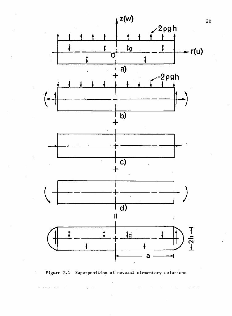
The s o l u t i o n o f the above ment ioned prob lem as r e p r e
sented i n F i g u r e 2.1 must s a t i s f y the f o l l o w i n g boundary
c o n d i t i o n s :
( < V z =.±h = °' ( T r z ) z = ±h = ° ( 2 ' 1 ^
f\(a ) dz = 0 -h r r = a
/ - h ( o r > r = a z d z = 0 > (2.2)
/_ n(T r z) r _ a2iTadz = weight o f the p l a t e .
A l l the c o n d i t i o n s o f (2.1) and (2.2) can be s a t i s f i e d
by s u p e r p o s i t i o n o f s e v e r a l e lementary s o l u t i o n s and the
e x p r e s s i o n s f o r d i s p l a c e m e n t s can be o b t a i n e d f o l l o w i n g
L o v e ' s t rea tment o f modera te ly t h i c k p l a t e s [ 7 ] .
F i r s t l e t us c o n s i d e r the p l a t e h e l d by a u n i f o r m l y
d i s t r i b u t e d t e n s i o n , F i g u r e 2.1a. I f the s o l u t i o n f o r a
p l a t e (without body f o r c e ) s u b j e c t e d to u n i f o r m compress ion
-2 pgh (F igure 2.1b) over the upper f ace i s super imposed ,
t t I. t
z(w) /2 P gh
t t t t f
2 0
n f I r(u)
a) + ^--2pgh
* * * * * * * * *
+ b)
Figure 2.1 S u p e r p o s i t i o n of s e v e r a l elementary s o l u t i o n s

21
the f a c e z = h w i l l be f r e e o f normal s t r e s s and the r e s u l t
i n g d i s p l a c e m e n t s w i l l be e n t i r e l y due to the body f o r c e .
But due t o the na tu re o f the second s o l u t i o n , t h e r e w i l l be
a moment and a r a d i a l f o r c e p r e s e n t a t the edge o f the p l a t e .
To r e l i e v e the edge o f the moment and the r a d i a l f o r c e ,
two o t h e r s o l u t i o n s need to be added, as shown i n F i g u r e 2 . 1 c , d .
T h i s l e a d s to the d e s i r e d s o l u t i o n o f s e l f - w e i g h t d e f l e c t i o n
o f a p l a t e suppor ted by u n i f o r m s h e a r i n g f o r c e s a l o n g the
edges .
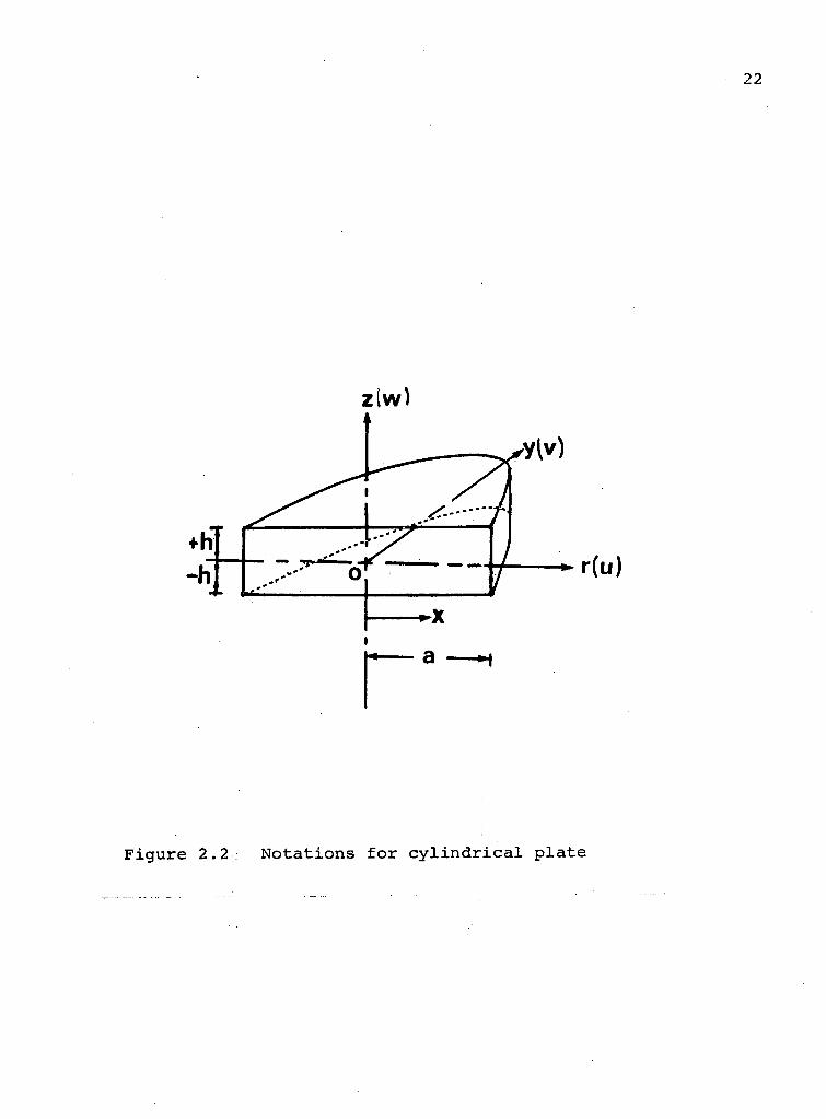
The n o t a t i o n s f o r the p l a t e , used i n the p r e s e n t
i n v e s t i g a t i o n are shown i n F i g u r e 2 . 2 . Body f o r c e d i s p l a c e
ments f o r a p l a t e h e l d by u n i f o r m l y d i s t r i b u t e d t e n s i o n on
i t s upper f ace are
u = - vpg(z+h)x/E
v = - vpg(z+h)y/E (2.3)
w = |̂(- ( z 2 + v x 2 + v y 2 + 2hz)
and i n absence o f a body f o r c e i t s d i s p l a c e m e n t s when s u b
j e c t e d to u n i f o r m compress ion - 2pgh over i t s upper f a c e ,
are
u = _ ( l + v ) ( 2 p g h ) x [ ( 2 _ v ) 2 3 _ 3 h 2 z _ 2 h 3 3
8 E h J q
v = _ ( l + v ) ( 2 p g h ) y [ ( 2 _ v ) z 3 _ ^2^ . 2 h 3 3 ( 1 _ v ) z ( x 2 + y 2 ) }
8 E h J *
z(w)
r
F i g u r e 2 . 2 N o t a t i o n s f o r c y l i n d r i c a l p l a t e
23
= < 1 + v ) < 2 ™ h ) [ ( l + v ) z 4 - 6 h V - 8 h 3 z + 3 ( h 2 - v z 2 ) ( x 2
+ y 2 ) 1 6 E h J
- | (1-v) ( x 2 + y 2 ) 2 ] (2.4)
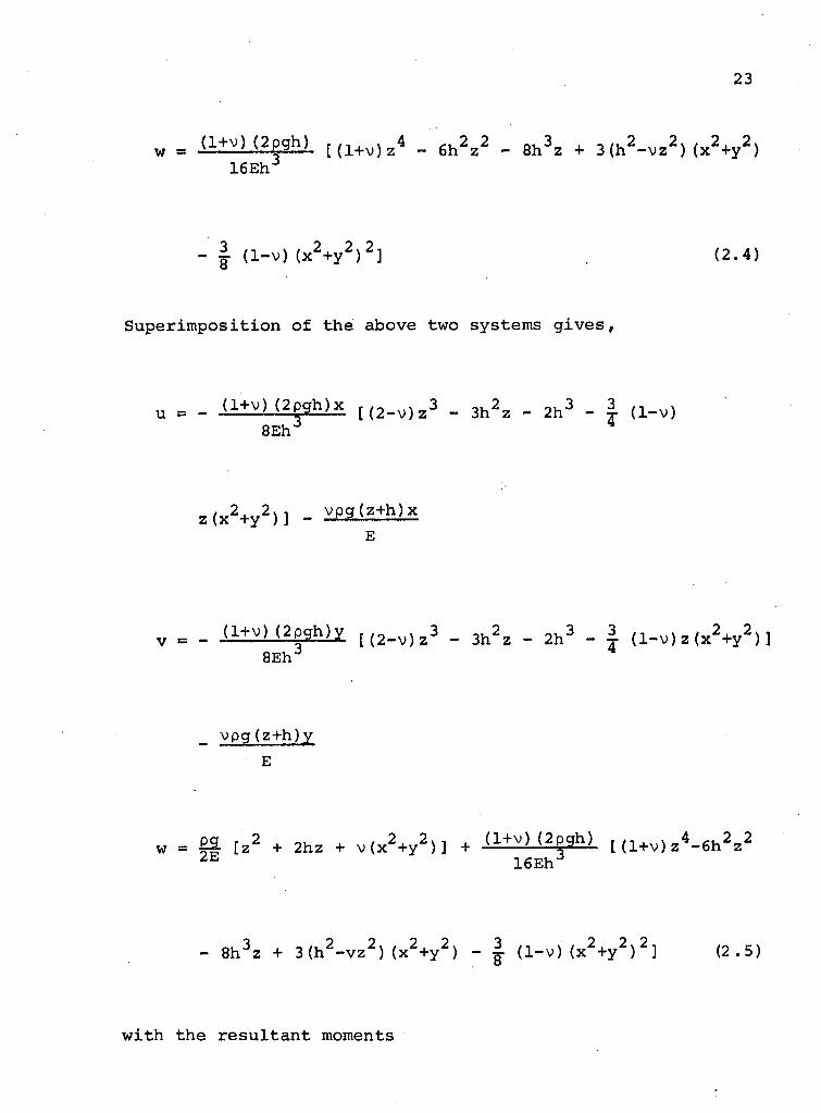
S u p e r i m p o s i t i o n o f the above two systems g i v e s ,
u = _ (1+v)(2pgh)x [ ( 2 _ v ) z 3 _ 3 h 2 2 _ 2 h 3 _ 3 ( 1 _ v )
8 E h J
z ( x 2 + y 2 } ] _ v p g ( Z + h ) x
E
v = _ (1+v) ( 2 p g h ) y [ ( 2 _ v ) z 3 „ 3 ^ _ 2 h 3 3 ( 1 _ v ) z ( x 2 + y 2 } j 8 E h J
vpg(z+h)y
E
= £SL [ z 2 + 2 h z + v ( x 2 + y 2 n + d+v) (2pgh) r ( 1 + v ) z<L 6 h2 z2 2 E 1 6 E h J
- 8 h 3 z + 3 ( h 2 - v z 2 ) ( x 2 + y 2 ) - | (1-v) ( x 2 + y 2 ) 2 ] (2.5)
w i t h the r e s u l t a n t moments
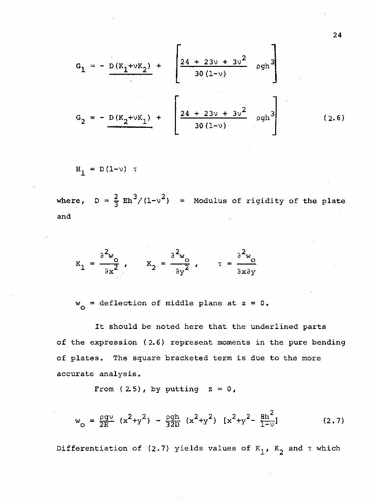
24
G l " D ( K 1 + V K 2 ) + 24 + 23v + 3v'
30(1-v) pgh"
G 2 = - DfKj+vl^) + 24 + 23v + 3v'
30(1-v) pgh" (2.6)
1^ = D ( l - V ) T
2 3 2 where, D = Eh /(1 -v ) = Modulus o f r i g i d i t y o f the p l a t e
and
2 2 2 3 w 3 w 3 w
K _ o K _ o T - ° x 3x^ ^ 3 y z 3x3y
w = d e f l e c t i o n o f midd le p lane a t z = 0. o ^
I t s h o u l d be noted here t h a t the u n d e r l i n e d p a r t s
o f the e x p r e s s i o n (2.6) r e p r e s e n t moments i n the pure bend ing
o f p l a t e s . The square b r a c k e t e d term i s due t o the more
a c c u r a t e a n a l y s i s .
From ( 2.5) , by p u t t i n g z = 0 ,
2 pgv , 2. 2. pgh , 2. 2 S r 2. 2 8h , n s
W o = 2E ( X + y ) ~ I2D ( X + Y } [ X + Y ' T^T ] ( 2 * 7 )
D i f f e r e n t i a t i o n o f (2.7) y i e l d s v a l u e s o f K^, and T which
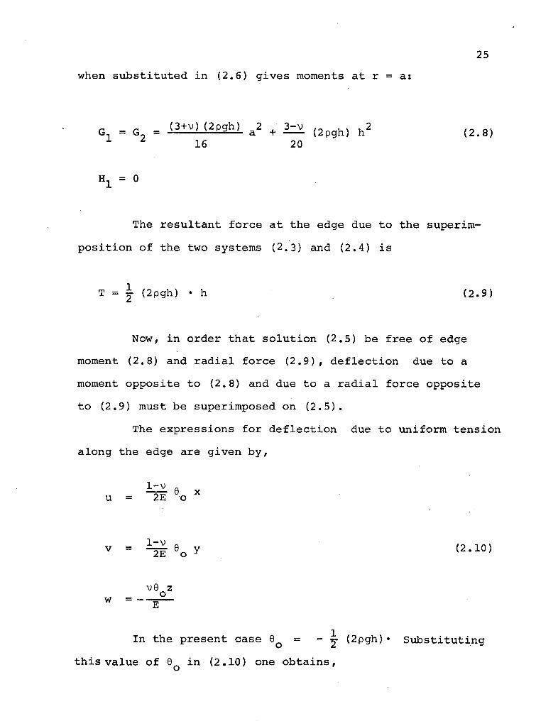
when s u b s t i t u t e d i n (2.6) g i v e s moments a t r = a :
G, = G„ = ( 3 + v ) ( 2 p g h ) a 2
+ ( 2 p g h ) h 2 ( 2 . 8 ) 16 20
H, = 0
The r e s u l t a n t f o r c e a t the edge due t o the s u p e r i m -
p o s i t i o n o f the two systems (2.3) and (2.4) i s
T = i (2pgh) • h (2.9)
Now, i n o r d e r t h a t s o l u t i o n (2.5) be f r e e o f edge
moment (2.8) and r a d i a l f o r c e ( 2 . 9 ) , d e f l e c t i o n due to a
moment o p p o s i t e to (2.8) and due t o a r a d i a l f o r c e o p p o s i t e
to (2.9) must be super imposed on ( 2 . 5 ) .
The e x p r e s s i o n s f o r d e f l e c t i o n due t o u n i f o r m t e n s i o n
a l o n g the edge are g i v e n b y ,
1-v Q
u = ~~2E~ o X
v = 9 o y (2.10)
w = -•
v6 z o
E
In the p r e s e n t case 6 Q = - ^ (2pgh)• S u b s t i t u t i n g
t h i s v a l u e o f 6Q i n (2.10) one o b t a i n s ,

26
u = - V2 E (pgh) • x
v = - (pgh) • y (2.11)
w = g- (pgh) • z
For determining d e f l e c t i o n due to a moment opposite
to that of (2.8), we choose a stress function x ^ of the form
X X = J 3(x 2+y 2) + Y , (2.12)
where 3 , Y = constants, giving
r 2 h 3 ^ c - 2 h 3 9 2 ) ( l
1 J 3y 3x^
Substituting the values of the derivatives of x ^ from (2.12)
i n the above expression,
G 1 = G 2 = | h 3 3 (2.13)
This must be negative of the value obtained i n (2.8). Hence,

27
3 = - ^ t f — (2pgh) a 2 + (2pgh)h 2 ]
with [ 7 ]
v = i (JyZ - i | i z (2.14)
Taking the reference for d e f l e c t i o n values at 0
(r, z, w = 0) ,
( w )r=0 = " §E (0) + ^ ( i 3 • 0 + y ) z=0
Y = 0
and X l = " -K I — (2pgh) a 2 + 3^.(2pgh) h 2 ] (x 2+y 2) (2.15) 1 4h 16 20
Now subs t i t u t i n g the values of and i t s derivatives i n (2.14)
the deflections due to a moment opposite to (2.8) are
obtained as:
28
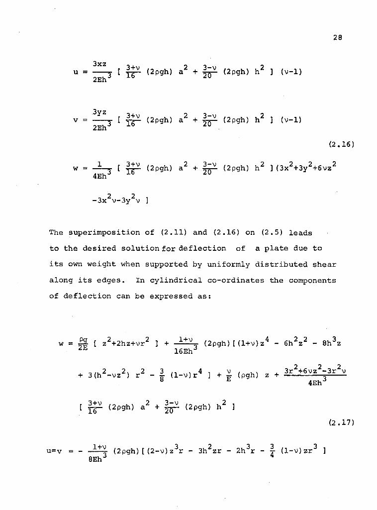
u = ffL [ (2pgh) a 2 + £2- (2pgh) h 2 ] (v-1) 2Eh,:J ± 0 ^ u
3y z v = , [ 3+̂ . ( 2 pgh) a 2 + f ^ - (2pgh) h 2 ] (v-1)
2Eh J ± Q z v •
(2.16)
2,^2, - 2 w = A , [ ̂ (2pgh) a 2 + i ^ . (2pgh) h 2 ] (3x2+3y2+6vz 4Eh J X b ^ u
2 2 -3x v-3y v ]
The superimposition of (2.11) and (2.16) on (2.5) leads
to the desired solution for d e f l e c t i o n of a plate due to
i t s own weight when supported by uniformly d i s t r i b u t e d shear
along i t s edges. In c y l i n d r i c a l co-ordinates the components
of d e f l e c t i o n can be expressed as:
w = P | [ z2+2hz+vr 2 ] + 1 + v , (2pgh)[ (l+v)z 4 - 6 h 2 z 2 - 8h 3z
2 E 16Eh J
^ , 2 2S 2 3 ,, 4 , . v , . . „ . 3r 2+6vz 2-3r 2v + 3(h -vz ) r - ^ ( l - v ) r ] + =• (pgh) z + =
8 E 4Eh 3
[ ^ (2pgh) a 2 + (2pgh) h 2 ] (2.17)
1+v t n , 4 r ,„ v 3 ^2 „,_3 3 ,., ..,3 u=v = -
8Eh j (2pgh)[(2-v)z r - 3h zr - 2h r - j ( l - v ) z r ]
29
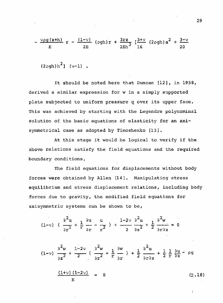
_ vpg(z-rh) r _ U - W ( p g h ) r + 3rz jS+v ( 2 p g h ) a 2 + 3^v
E 2E 2Eh 16 20
(2pgh)h 2] (v-1) .
It should be noted here that Duncan [12], i n 1958,
derived a s i m i l a r expression for w i n a simply supported
plate subjected to uniform pressure q over i t s upper face.
This was achieved by s t a r t i n g with the Legendre polynominal
solution of the basic equations of e l a s t i c i t y for an a x i -
symmetrical case as adopted by Timoshenko [13].
At t h i s stage i t would be l o g i c a l to v e r i f y i f the
above rel a t i o n s s a t i s f y the f i e l d equations and the required
boundary conditions.
The f i e l d equations for displacements without body
forces were obtained by A l l e n [14]. Manipulating stress
equilibrium and stress displacement r e l a t i o n s , including body
forces due to gravity, the modified f i e l d equations for
axisymmetric systems can be shown to be,
8 2u , 3u u l-2v 9 2u , 92w (1-v) { + ±- , } + 2 + 7 = 0
9r dr r 2 az * 3r9z
32w l-2v 92w , 8w , 9 2u , , « (1-v) + { + ~ } + - + £ i °R - pg
< 1 + v ) < 1 - 2 v ) = 0 ( 2 . 1 8 )
1
30
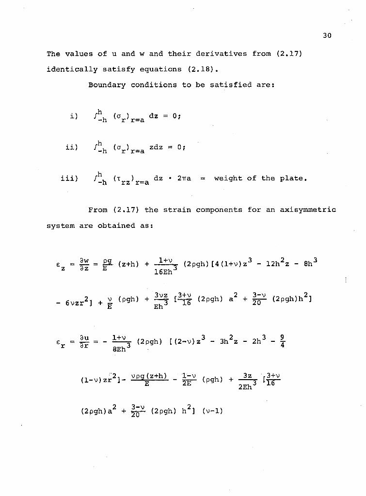
The v a l u e s o f u and w and t h e i r d e r i v a t i v e s from (2.17)
i d e n t i c a l l y s a t i s f y e q u a t i o n s ( 2 . 1 8 ) .
Boundary c o n d i t i o n s t o be s a t i s f i e d a r e :
i ) fh, (a ) dz = 0; ' -h r r=a
i i ) f^h ( ^ r ) r = = a
z d z = 0;
h i i i ) / , (T ) dz • 2ira = weight o f the p l a t e , -h r z r=a
From (2.17) the s t r a i n components f o r an ax i symmet r i c
system are o b t a i n e d a s :
E = |£ = £3. (z+h) + 1 + v . , (2pgh) [ 4 ( l + v ) z 3 - 1 2 h 2 z - 8h :
z d z * 16Eh
- e v z r 2 ] + i ( ^ h ) + i r ! ( 2 p ^ h ) * 2 + f i r < 2 ^ h ^ E Eh
e = | H = - i±}L. ( 2 pgh) t ( 2 - v ) z 3 - 3h 2 z - 2 h 3 - I r 3 r 8 E h 3 4
, 2, vpg (z+h) 1-v t n „ u \ . 3z r ( l - v ) z r ] - j g - (pgh) + — ^ I ^ -3+v
(2pgh)a 2 + (2pgh) h 2 ] (v-1)
31
u ~ 1 + V j (2pgh) [(2-v)z 3 - 3h 2z - 2h 3 - | ( l - v ) z r 2 ] r 8Eh
vpg(z+h) 1-v , .» , 3z r3+v / 0 . . (pgh) + [y^— • (2pgh) a E 2E 2Eh J • L O
+ i z v . (2pgh) h 2] (v-1) 20
+ S t = 3 ( l - r v ) ( 2 P g h ) (h 2r - z 2 r ) (2.19) au _ 3 z 1 .ar - 4 E h 3
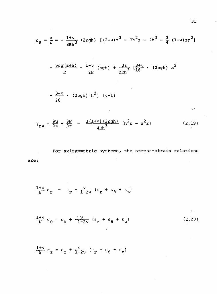
For axisymmetric systems, the s t r e s s - s t r a i n r e l a t i o n s
= e + Jv„ (e + e„ + e ) r r l-2v v r 8 z'
e = e e + "I=3v ( e r + e e + ez> ( 2 ' 2 0 )
z z l-2v r 8 z

32
1+v rz 2 Yrz
Substituting the values of the s t r a i n components from (2.19)
i n (2.20) and simplifying one obtains,
o = r " (1+v) (1 ±=±jy (2pgh) [4z 3(l+v)-6h 2z-4h 3-6vzr :
- 2z 3(2-v) + | ( l - v ) z r 2 ] - 2z 3(2-v)+6h 2z+4h 3+|(l+v)zr 2 }
+ ^ P S h - v p g ( z + h ) - £$*L + { 3+*. (2pgh)a 2+ | ^ (2pgh)h 2} (1-v)
_ 2 3y z h 3 ( l - v )
20
3z
" (l+v)(I-2v) f 77 T T < 2"*> { lh 1 4 Z3 ( l + v ) - 6 h 2
Z - 4 h 3 - 6 v z r :
|_ I o n
- 2z 3(2-v)+ | ( l - v ) z r 2 ]- 2z 3(2-v)+6h 2z+4h 3+|(l-v)zr 2 }
+ ii_ea*L - vpg(z-rh)- £|1 + . (2pgh)a 2+ 3Z^(2pgh)h 2 } (1-v) 20
33
•f 3v z 3z -,
h J ( l - v ) h J
a = z
1-v
(1+v)( l -2v) i — (2pgh) { [ - 2 z 3 ( 2 - v ) + 6 h 2 z + 4 h 3 ] + 2 z 3
8 h J X " V
+ 2 v z 3 - 6 h 2 z - 4 h 3 } + pg(z+h) - 2 v 2 pg(z+h) J
1-v J
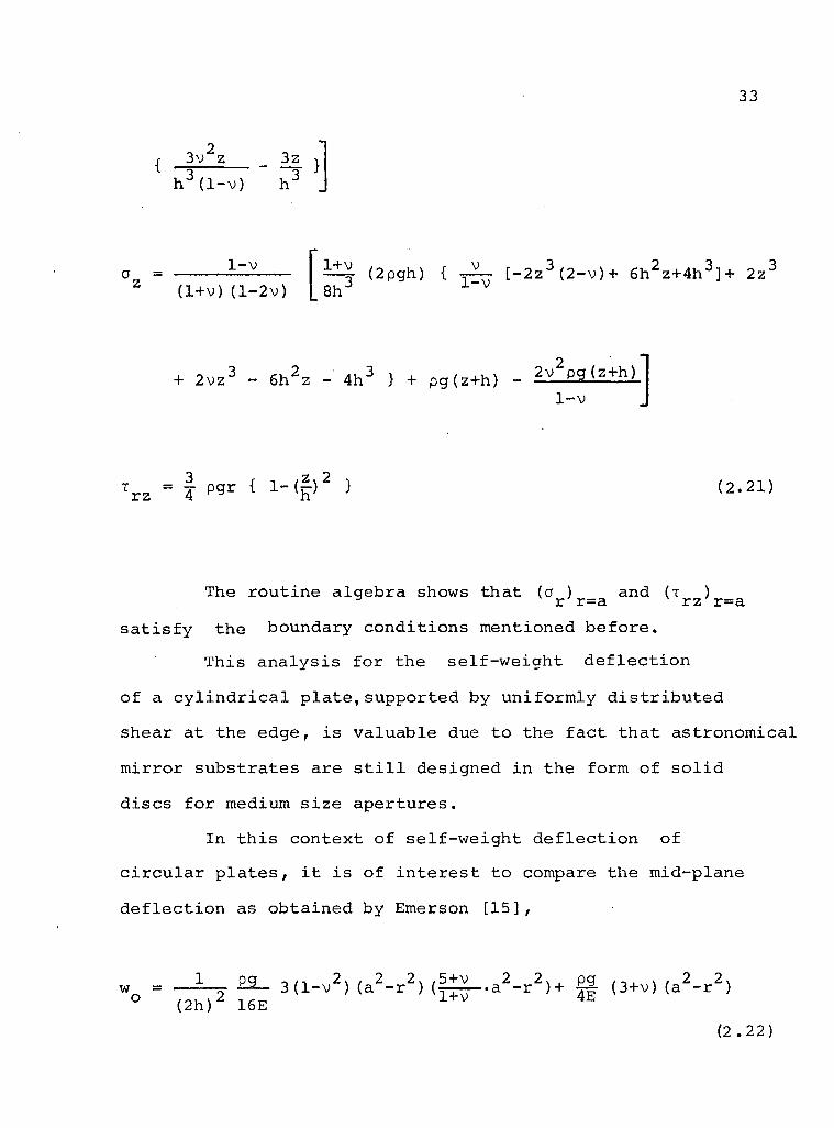
x r z - I pgr { l - ( £ ) 2 } (2.21)
The r o u t i n e a l g e b r a shows t h a t (a ) and (x ) ^ r r=a r z r=a
s a t i s f y the boundary c o n d i t i o n s ment ioned b e f o r e .
T h i s a n a l y s i s f o r the s e l f - w e i g h t d e f l e c t i o n
o f a c y l i n d r i c a l p l a t e , s u p p o r t e d by u n i f o r m l y d i s t r i b u t e d
shear a t the edge , i s v a l u a b l e due to the f a c t t h a t a s t r o n o m i c a l
m i r r o r s u b s t r a t e s are s t i l l des igned i n the form of s o l i d
d i s c s f o r medium s i z e a p e r t u r e s .
In t h i s c o n t e x t o f s e l f - w e i g h t d e f l e c t i o n o f
c i r c u l a r p l a t e s , i t i s o f i n t e r e s t t o compare the mid -p lane
d e f l e c t i o n as o b t a i n e d by Emerson [ 1 5 ] ,
w = pg (2h) 16E
2 w 2 2, -5+v 3 (1-v ) (a - r ) (, •1+v
2 2 X , • a - r ) + | | (3+v) ( a 2 - r 2 )
(2 .22)
34
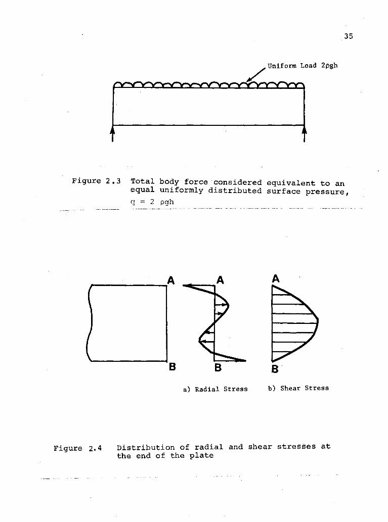
The above expression assumes that the t o t a l body force of
the plate i s equivalent to an equal uniformly d i s t r i b u t e d
surface pressure q = 2pgh (Figure 2.3).
2 • 3 Results and Discussion
For the plate supported by uniformly d i s t r i b u t e d
shear, the d i s t r i b u t i o n of r a d i a l and shear stress at the
end of the plate i s shown i n Figure 2.4. The v a r i a t i o n of
r a d i a l stress at an intermediate cross-section i s indicated
in Figure 2.5. It i s clear that the net r a d i a l force at
any cross-section i s zero but only the edge of the plate i s
free of moment. Furthermore, the d i s t r i b u t i o n of shear i s
parabolic.
The v a r i a t i o n of a x i a l stress a as obtained from z
the present investigation, equation (2.21), i s shown in
Figure 2.6a with the d i s t r i b u t i o n of for the boundary
and loading conditions of Figure 2.3 shown i n Figure 2.6b
t13]• It i s i n t e r e s t i n g to note that the expression (2.22),
being approximate (distributed body force replaced by a
uniform loading), v i o l a t e s the boundary condition of zero
normal stress over the top face of the plate (Figure 2.6b)
whereas the d i s t r i b u t i o n of a obtained from the present
analysis s a t i s f i e s the boundary conditions of zero normal
stress over the top and bottom faces of the plate exactly
(Figure 2.6a). A comparison of the middle plane deflections
as obtained from (2.17) and (2.22) i s shown in Figure 2.7.
Here the numerical values of physical parameters correspond
35
Uniform Load 2pgh
F i g u r e 2 .3 T o t a l body f o r c e c o n s i d e r e d e q u i v a l e n t t o an e q u a l u n i f o r m l y d i s t r i b u t e d s u r f a c e p r e s s u r e ,
a pgh
B
a) R a d i a l S t r e s s b) Shear St r e s s
F i g u r e 2« 4 D i s t r i b u t i o n o f r a d i a l and shear s t r e s s e s a t the end o f the p l a t e

37
F i g u r e 2 .6 A x i a l s t r e s s d i s t r i b u t i o n
Middle Surface
•dr 2f - B a — n H 6
Present Theory
Emerson
- 2 5 0
2 0 0
150
CO
100
5 0
o o o o o
TO
Comparison between the middle s u r f a c e d e f l e c t i o n s as o b t a i n e d from the p r e s e n t t h e o r y (equat ion 2.17) and Emerson 's a n a l y s i s (equat ion 2.22) :
E = 10.5 x 10 ; v = 0 .17 ; p = 0.0795

3 9
to that for fused s i l i c a , a conventional substrate material. As evident from equation (2.21), the d i s t r i b u t i o n of
r a d i a l stress i s non-linear. This may be attributed to the
e f f e c t of shearing stresses and normal pressures on the planes
p a r a l l e l to the surface of the plate. However, the e f f e c t
of non-linearity i n the case considered appears to be rather
n e g l i g i b l e (Figure 2.5). The r a d i a l stresses at the edge
are not zero (Figure 2.4a) but the resultant of these stresses
and t h e i r moments indeed vanish. Hence, on the basis of
Saint Venant's P r i n c i p l e , we can say that the removal of
these stresses does not a f f e c t the stress d i s t r i b u t i o n i n
the plate s i g n i f i c a n t l y at some distance away from the edge.
The expression for l a t e r a l d e f l e c t i o n w, equation
(2.17), shows i t to be a function of r and z thus suggesting
d i f f e r e n t shapes for top and bottom surfaces compared to the
mid-plane. This difference increases as the diameter to
thickness r a t i o decreases. Hence for thick c y l i n d r i c a l mirror
substrates, prediction of top surface d e f l e c t i o n from the
mid-plane analysis (as i s done i n the approximate theories)
i s not f u l l y j u s t i f i e d . Thus for accurate determination of
the top surface d e f l e c t i o n the present analysis should prove
useful. Figure 2.8 compares the deflections of the middle
and outer surfaces.
I t should be noted here that, as the outer surfaces
and middle plane (Figure 2.8) assume d i f f e r e n t shapes when
flexed, t h e i r r a d i i of curvature would not d i f f e r merely
by t h e i r normal distance apart; t h i s i n t e r v a l w i l l not be a
constant function of r. Thus the present analysis accurately

41
shows the f i n e r d e t a i l s of e l a s t i c deformation patterns,
which may be relevant i n c a l c u l a t i n g the curvatures of outer
faces. The curvature of the flexed dis c follows r e a d i l y
from (2.17).
In order to investigate the influence of shear, the
results based on present analysis are compared with the t h i n
plate theory i n Figure 2.9. The discrepancy i n d e f l e c t i o n
values increases rapidly as the diameter/thickness r a t i o i s
decreased (3.4% for D/H=10, 21.7% for D/H=4). Furthermore,
the d e f l e c t i o n diminishes quite rapidly as the D/H i s
decreased. That explains massive character of mirror substrates
where r i g i d i t y i s b u i l t up more rapidly than the associated
body forces.
It should be noted that a continuous support by
way of the p a r a b o l i c a l l y d i s t r i b u t e d shear i s not practicable.
A l o g i c a l s i m p l i f i c a t i o n i s to concentrate shear reactions
at three equispaced boundary points or at s i x i n t e r n a l
points, as mentioned e a r l i e r i n Chapter 1. These would induce
more s t r a i n compared to a continuous support because of
additional i n t e r n a l transmission of body forces to reactive
points. However, when a mirror substrate i s supported on
three equispaced pads, the problem becomes s t r i c t l y three
dimensional and one has to resort to numerical methods
aided by a d i g i t a l computer or experimental studies of
models.
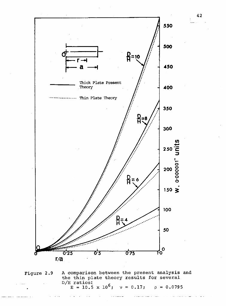
r/a A compar ison between the p r e s e n t a n a l y s i s and the t h i n p l a t e t h e o r y r e s u l t s f o r s e v e r a l D/H r a t i o s :
E = 10.5 x 10°; v = 0.17; p = 0.0795
F i g u r e 2.9

43
As there i s a s i m i l a r i t y i n the nature of the body
force and thermally induced e f f e c t s i n e l a s t i c s o l i d s , i t
i s appropriate, i n t h i s context, to comment on the thermally
induced displacements.
When the temperature i n a small portion of the body
i s increased by T, d i l a t a t i o n proportional to T can be
produced without a corresponding change i n pressure. This
implies extension of a l l l i n e a r elements by aT, where a i s
the c o e f f i c i e n t of thermal expansion. In addition, i f
forces are applied to the body,the corresponding s t r a i n
obtained from s t r e s s - s t r a i n r e l a t i o n would augment the
thermal e f f e c t . Thus i t follows that the displacement due
to the thermal e f f e c t i s i d e n t i c a l to that produced by a 06 £
body force expressed as the gradient of - Y-2\> T / an& cxE!
normal surface pressure Y-2'V T l ^ ]. These would be
i n addition to the actual body force and surface t r a c t i o n
present i n the system.
Thus, the a n a l y t i c a l expressions derived for the
body force case may be used to determine thermally induced
displacements. On the other hand, thermally induced d i s
placements can be determined quite r e a d i l y using f i n i t e
element procedures as explained i n the following chapter.
3. NUMERICAL ANALYSIS OF THICK CIRCULAR PLATES OF VARIABLE THICKNESS AND ITS APPLICATION TO THE DESIGN OF MIRROR SUBSTRATES
An ax i symmetr i c e l a s t i c system may be d e s c r i b e d by
c y l i n d r i c a l c o o r d i n a t e s as shown i n F i g u r e 3 . 1 . Due to
symmetry i n geometry and l o a d i n g about the v e r t i c a l a x i s z ,
the system deforms o n l y i n r a d i a l and v e r t i c a l d i r e c t i o n s .
A l s o s t r e s s e s and s t r a i n s do not v a r y i n the t a n g e n t i a l
d i r e c t i o n . Thus , from a mathemat i ca l p o i n t o f v i ew , the
problem i s o n l y two d i m e n s i o n a l and i t i s s u f f i c i e n t to
a n a l y z e any a x i a l z - r p lane as shown i n F i g u r e 3 . 2 . The s t r u c
t u r a l forms shown i n column 2 o f F i g u r e 1.5 r e p r e s e n t
ax i symmetr i c sys tems . S e v e r a l n u m e r i c a l t e c h n i q u e s are
a v a i l a b l e which may be used f o r s o l v i n g problems o f the
p r e s e n t k i n d . I t would be u s e f u l t o comment on these p r o
cedures b e f o r e t r e a t i n g the prob lem i n hand.
3.1 A B r i e f Review o f the Numer i ca l Techn iques
3 . 1 . 1 F i n i t e D i f f e r e n c e Method
T h i s i s p r o b a b l y the most w i d e l y used n u m e r i c a l
t e c h n i q u e f o r s o l v i n g a v a r i e t y o f f i e l d p rob lems , i n c l u d i n g
those i n e l a s t i c i t y . The m a j o r i t y o f the problems i n s t r e s s
a n a l y s i s , when t a c k l e d by a t h e o r e t i c a l approach , reduce to
the s o l u t i o n o f one o r more d i f f e r e n t i a l e q u a t i o n s w i t h
s p e c i f i e d b o u n d a r y c o n d i t i o n s on s t r e s s o r d i s p l a c e m e n t .

45
F i g u r e 3.1 Ax i symmetr i c s o l i d F i g u r e 3.2 A x i a l z - r p lane

46
In the f i n i t e d i f f e r e n c e method, the g o v e r n i n g
e q u a t i o n s o f e l a s t i c i t y and boundary c o n d i t i o n s are r e p l a c e d
by a f i n i t e number o f unknown v a l u e s o f the dependant
v a r i a b l e s a t a number o f d i s c r e t e nodes , formed by a g r i d -
work, w i t h i n and over the boundary o f the domain.
The prob lem can be f o r m u l a t e d i n terms o f s t r e s s
f u n c t i o n s [16] o r d i s p l a c e m e n t components [ 1 4 ] , the c h o i c e b e i n g
l a r g e l y governed by the s p e c i f i c a t i o n o f the boundary c o n d i t i o n s
i n terms o f s t r e s s , d i s p l a c e m e n t o r b o t h .
In the fo rmer , the v a l u e s o f s t r e s s f u n c t i o n s o b t a i n e d
f o r the nodes g i v e o n l y an i n t e r m e d i a t e s o l u t i o n to a
p a i r o f g o v e r n i n g e q u a t i o n s . A combinat ion o f the d e r i v a t i v e s
o f the s t r e s s f u n c t i o n s y i e l d the r e q u i r e d s t r e s s components.
On the o t h e r h a n d , w i t h the d i s p l a c e m e n t f o r m u l a t i o n , the
components o f d i s p l a c e m e n t s a re o b t a i n e d d i r e c t l y . A
s u i t a b l e combinat ion o f the d e r i v a t i v e s o f d i s p l a c e m e n t s g i v e
the s t r e s s components.
Once the g e n e r a l f o r m u l a t i o n o f the problem i s
e s t a b l i s h e d , the e l a s t i c r e g i o n to be s t u d i e d i s
s y s t e m a t i c a l l y d i v i d e d up by a system of c o o r d i n a t e p l a n e s
i n t e r s e c t i n g a l o n g l i n e s and at nodes . Now g o v e r n i n g e q u a t i o n s
i n terms o f n o d a l s t r e s s f u n c t i o n v a l u e s have t o be s a t i s f i e d .
These f i n i t e d i f f e r e n c e e q u a t i o n s r e p r e s e n t a s e t o f l i n e a r
a l g e b r a i c r e l a t i o n s to be s o l v e d f o r unknown s t r e s s f u n c t i o n s ,
i n g e n e r a l , by a d i g i t a l computer .

47
A s o l u t i o n o b t a i n e d by the f i n i t e d i f f e r e n c e method
i s always i n e r r o r , however s m a l l . These e r r o r s may be
reduced i n two ways [17 J :
i ) by employ ing a v e r y f i n e mesh s i z e so t h a t the
e r r o r s due to n e g l e c t e d h i g h e r o r d e r terms i n
T a y l o r ' s s e r i e s expans ions are n e g l i g i b l e ;
i i ) by i n c l u d i n g s u f f i c i e n t l y h i g h o r d e r d i f f e r e n c e s
i n f i n i t e d i f f e r e n c e formulae based on a
coa rse mesh.
Both the p rocedures have d i s a d v a n t a g e s . The f i r s t
a l t e r n a t i v e may appear to be t h e o r e t i c a l l y a t t r a c t i v e as
e r r o r s d e c r e a s e i n d e f i n i t e l y w i t h a mesh s i z e . However, w i t h
a f i n e mesh, the number o f e q u a t i o n s becomes v e r y l a r g e and
the e f f o r t s i n v o l v e d i n o b t a i n i n g a s o l u t i o n ge ts p r o h i b i t i v e .
F u r t h e r m o r e , round o f f e r r o r s a l s o i n c r e a s e . The a l t e r n a t i v e
would be t o use more n o d a l p o i n t s i n the g o v e r n i n g e q u a t i o n s .
T h i s l e a d s to e x t e n s i v e m a n i p u l a t i o n s t o e l i m i n a t e the
f i c t i t i o u s f u n c t i o n v a l u e s r e p r e s e n t i n g the s t r e s s o r
d i s p l a c e m e n t f u n c t i o n s a t nodes o u t s i d e the boundary o f the
p rob lem. The f i c t i c i o u s q u a n t i t i e s are e l i m i n a t e d by u s i n g
the s p e c i f i e d boundary c o n d i t i o n s . F u r t h e r , due t o the
i n c l u s i o n o f remote nodes , the l o c a l a c c u r a c y might be
a f f e c t e d .
A comment c o n c e r n i n g a r e l a t i v e l y new n u m e r i c a l
p r o c e d u r e , deve loped by Day [18] and O t t e r e t a l . [19]
48
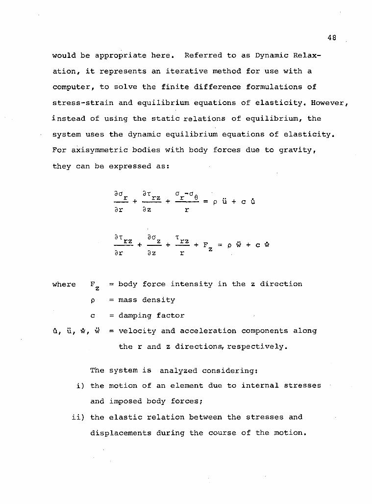
w o u l d b e a p p r o p r i a t e h e r e . R e f e r r e d t o a s D y n a m i c R e l a x
a t i o n , i t r e p r e s e n t s a n i t e r a t i v e m e t h o d f o r u s e w i t h a
c o m p u t e r , t o s o l v e t h e f i n i t e d i f f e r e n c e f o r m u l a t i o n s o f
s t r e s s - s t r a i n a n d e q u i l i b r i u m e q u a t i o n s o f e l a s t i c i t y . H o w e v e r ,
i n s t e a d o f u s i n g t h e s t a t i c r e l a t i o n s o f e q u i l i b r i u m , t h e
s y s t e m u s e s t h e d y n a m i c e q u i l i b r i u m e q u a t i o n s o f e l a s t i c i t y .
F o r a x i s y m m e t r i c b o d i e s w i t h b o d y f o r c e s d u e t o g r a v i t y ,
t h e y c a n b e e x p r e s s e d a s :
r . r z . r 6 » , + + = p u + c u
3r 3z r
3T 3a T + — z + _ r z + p = p w + c w
3r 3z r Z .
w h e r e = b o d y f o r c e i n t e n s i t y i n t h e z d i r e c t i o n
p = m a s s d e n s i t y
c = d a m p i n g f a c t o r
u , v i , w , w = v e l o c i t y a n d a c c e l e r a t i o n c o m p o n e n t s a l o n g
t h e r a n d z d i r e c t i o n s , r e s p e c t i v e l y .
T h e s y s t e m i s a n a l y z e d c o n s i d e r i n g :
i ) t h e m o t i o n o f a n e l e m e n t d u e t o i n t e r n a l s t r e s s e s
a n d i m p o s e d b o d y f o r c e s ;
i i ) t h e e l a s t i c r e l a t i o n b e t w e e n t h e s t r e s s e s a n d
d i s p l a c e m e n t s d u r i n g t h e c o u r s e o f t h e m o t i o n .

49
The object of the c a l c u l a t i o n i s not, however, to study
the motion but to determine s t a t i c stresses and displacements
of a structure. This i s achieved by an i t e r a t i v e procedure.
Thus the method i s e s s e n t i a l l y a step-by-step integration
of damped v i b r a t i o n , using viscous damping,to ensure a t t a i n
ment of steady state solution.
A t y p i c a l i t e r a t i o n s t a r t s at t = 0, with a r b i t r a r i l y
chosen i n i t i a l conditions except at the boundary where d i s
placements and/or stresses are s p e c i f i e d . I n i t i a l l y , d i s
placements and v e l o c i t i e s may be chosen to be zero except at
the boundary. Substitution of chosen displacements i n the
stress displacement equations, gives stresses. The stresses
are then introduced i n the equilibrium equations to obtain
new v e l o c i t i e s . The new displacements at time t^= t + At
are obtained from the velocity-displacement r e l a t i o n ,
u^= u + uAt.
The next i t e r a t i v e step begins with the c a l c u l a t i o n
of stresses from the stress-displacement r e l a t i o n . The new
stresses are then substituted i n the equilibrium equations.
The process continues u n t i l v e l o c i t i e s and accelerations
diminish and the r i g h t hand side of the equilibrium equation
approximates to zero, thus s a t i s f y i n g the condition of
s t a t i c equilibrium.
Dynamic relaxation seems to be a very powerful
numerical technique, however, the reference system used
should be such that the coordinate surfaces conform to the

50
s u r f a c e s o f the body. Fo r curved b o u n d a r i e s c u r v i l i n e a r
c o o r d i n a t e s have to be u s e d . Mixed boundary c o n d i t i o n s
i n v o l v i n g s t r e s s e s and d i s p l a c e m e n t s do not pose any prob lem.
The main d i s a d v a n t a g e o f the method i s the d e r i v a t i o n
o f the t ime i n t e r v a l and the damping f a c t o r . S u i t a b l e v a l u e s
have t o be determined by t r i a l and e r r o r .
As can be e x p e c t e d , the a c c u r a c y o f the method
depends on the element s i z e u s e d . The r e s u l t s o b t a i n e d by
dynamic r e l a x a t i o n compare f a i r l y w e l l w i t h those due t o
o t h e r methods [18, 1 9 ] .
3 . 1 . 2 I n t e g r a l Method
I n t e g r a l methods a re f u n d a m e n t a l l y d i f f e r e n t f rom
the f i n i t e d i f f e r e n c e and f i n i t e e lement approaches . Here
a number o f f i c t i c i o u s c o n c e n t r a t e d o r l o c a l l y d i s t r i b u t e d
l o a d s , o f a r b i t r a r y v a l u e s , are a p p l i e d a l o n g the boundary
o f the model . T h e i r t o t a l e f f e c t a t an i n t e r i o r p o i n t i s
expressed as an a n a l y t i c a l summation o f the e f f e c t s o f the
i n d i v i d u a l l o a d s [ 2 0 ] .
In p lane p rob lems , f o r i n s t a n c e , the f o r c e s a p p l i e d
a t the boundary can be c o n c e n t r a t e d l oads g i v i n g r i s e to a
r a d i a l s t r e s s [21] ( a = c-°. s 9 ) w i t h i n the f i e l d . A t r TT r
the boundary , the i n t e r i o r s t r e s s e s must e q u i l i b r a t e the
e x t e r i o r s t r e s s and from t h i s c o n d i t i o n the d i s t r i b u t i o n
o f the c o n c e n t r a t e d f i c t i c i o u s l o a d s a l l over the boundary
are d e t e r m i n e d .

51
F o r ax i symmetr i c s o l i d s B o u s s i n e s q ' s s o l u t i o n o f a
f o r c e a p p l i e d n o r m a l l y t o the boundary and g i v i n g r i s e t o
s t r e s s e s a , a f l , a , x may be u s e d . The i n t e g r a t e d e f f e c t 2T t) Z JL Z
o f these components o f s t r e s s e s a t i n t e r i o r p o i n t s f o r
e v e r y f i c t i t i o u s l o a d a p p l i e d on the boundary has t o be
o b t a i n e d . A t the boundary , the sum o f i n t e r i o r s t r e s s e s
due t o a l l s u r f a c e l o a d s has to be equated t o the e x t e r n a l l y
a p p l i e d boundary s t r e s s .
I n t e g r a l methods i n v o l v e fewer unknowns than f i n i t e
d i f f e r e n c e o r f i n i t e e lements t e c h n i q u e s . They a l s o
r e s u l t i n system of e q u a t i o n s w i t h f u l l m a t r i c e s (meaning i
t h e r e are not many z e r o terms i n the c o e f f i c i e n t mat r ix )
whereas d i f f e r e n c e methods i n v o l v e spa rse m a t r i c e s o f
h i g h e r o r d e r .
U s u a l l y the i n t e g r a l p rocedures g i v e more a c c u r a t e
r e s u l t s than the f i n i t e d i f f e r e n c e method, as the s t r e s s e s
are o b t a i n e d d i r e c t l y from the a n a l y t i c a l e x p r e s s i o n f o r the
summation o f the s e p a r a t e e f f e c t s o f the i n d i v i d u a l boundary
l o a d s . On the o t h e r hand , i n the f i n i t e d i f f e r e n c e method
the s t r e s s components depend on approximate d e r i v a t i v e s o f
the d i s c r e t e s t r e s s f u n c t i o n s .
52
3 .1 .3 F i n i t e Element Method
The f i n i t e e lement method i s e s s e n t i a l l y a g e n e r a l
i z a t i o n o f the t h e o r y o f s t r u c t u r a l a n a l y s i s . I t makes
p o s s i b l e the a n a l y s i s o f two-and t h r e e - d i m e n s i o n a l e l a s t i c
c o n t i n u a by the techn ique s i m i l a r t o t h a t used i n the a n a l y s i s
o f o r d i n a r y framed s t r u c t u r e s .
The method was i n t r o d u c e d o r i g i n a l l y by Turner e t
a l . [22] f o r the s o l u t i o n o f complex s t r u c t u r a l problems
encountered i n the a i r c r a f t i n d u s t r y .
The impor tan t concept i n t r o d u c e d by the f i n i t e e lement
method i s the use o f two- o r t h r e e - d i m e n s i o n a l s t r u c t u r a l
e lements t o r e p r e s e n t an e l a s t i c cont inuum. The r e a l
cont inuum i s assumed to be d i v i d e d i n t o a f i n i t e number o f
e lements i n t e r c o n n e c t e d a t a f i n i t e number o f nodes . An
approx imat ion which i s employed i n f i n i t e e lement t e c h n i q u e s
i s o f a p h y s i c a l n a t u r e ; a m o d i f i e d s t r u c t u r a l system i s
s u b s t i t u t e d f o r the a c t u a l cont inuum. T h i s d i s t i n g u i s h e s
the f i n i t e e lement t e c h n i q u e from f i n i t e d i f f e r e n c e method,
where , as seen b e f o r e , the e x a c t e q u a t i o n s o f the a c t u a l
p h y s i c a l system are s o l v e d by approximate mathemat i ca l
p r o c e d u r e s .
I t s h o u l d be r e c o g n i z e d t h a t the concept o f m o d e l l i n g
an e l a s t i c cont inuum by an assembly o f s t r u c t u r a l e lements
i s not new. In f a c t , the development o f the f i n i t e e lement
concept has stemmed from an e f f o r t t o improve on the
53
Hrenn iko f f -McHenry [23,24] ' l a t t i c e a n a l o g y 1 f o r r e p r e s e n t i n g
p lane s t r e s s systems [ 2 5 ] . Important s teps i n v o l v e d i n the
a n a l y s i s may be summarized as below [ 2 6 , 2 7 ] :
i ) S t r u c t u r a l I d e a l i z a t i o n - D i v i s i o n o f the e l a s t i c
cont inuum, t o be a n a l y z e d , . i n t o an a p p r o p r i a t e l y
shaped f i n i t e e l ements ,
i i ) E lement A n a l y s i s - E v a l u a t i o n o f the s t i f f n e s s
m a t r i x f o r every element by r e l a t i n g the f o r c e s
deve loped at the e lement n o d a l p o i n t s t o the
c o r r e s p o n d i n g element d i s p l a c e m e n t s ,
i i i ) Assembly A n a l y s i s - E v o l u t i o n o f the assembly
s t i f f n e s s m a t r i x f o r the complete s t r u c t u r e by
the s u p e r p o s i t i o n o f a p p r o p r i a t e e lement s t i f f
nesses and d e t e r m i n a t i o n o f unknown n o d a l
d i s p l a c e m e n t s by the s o l u t i o n o f the e q u i l i b r i u m
e q u a t i o n s .
Fo r the p r e s e n t p rob lem, the f i n i t e e lement approach
was c o n s i d e r e d t o be w e l l s u i t e d as the curved b o u n d a r i e s
o f the a rched geometr ies can be r e a d i l y i d e a l i z e d by the use
o f t r i a n g u l a r e l e m e n t s . The r e q u i r e d d e f l e c t i o n can be
o b t a i n e d d i r e c t l y and the mixed boundary c o n d i t i o n s pose no
prob lem. F u r t h e r m o r e , therma l e f f e c t s can be t r e a t e d u s i n g
the normal p r o c e d u r e .

54
3.2 L i g h t - W e i g h t M i r r o r S u b s t r a t e Des ign P h i l o s o p h i e s
The s e l f - w e i g h t problem a s s o c i a t e d w i t h l a r g e m i r r o r s
has l ong been r e c o g n i z e d . The s o l i d d i s c i s not an optimum
s t r u c t u r e s i n c e m a t e r i a l near the midd le p l a n e , when i t s a x i s
c o i n c i d e s w i t h the d i r e c t i o n o f g r a v i t y , i s no t f u l l y s t r e s s e d .
Hence, i t i s a t t r a c t i v e t o d e v e l o p , f o r both ground and space
a p p l i c a t i o n s , s t r u c t u r a l forms i n which such u n d e r s t r e s s e d
m a t e r i a l has been r e d i s t r i b u t e d or removed t o more e f f e c t i v e
l o c a t i o n s . S e v e r a l p rocedures f o r a c h i e v i n g t h i s are a p p a r e n t .
The most common would be the use o f sandwiched and r i b b e d s t r u c
t u r e s , web and f l a n g e c o n s t r u c t i o n , a r c h c o n c e p t , e t c . [ 6 , 2 8 , 2 9 ] .
L i g h t we ight m i r r o r s have been s u c c e s s f u l l y manufac
t u r e d f o r s a t e l l i t e and ground a p p l i c a t i o n s by the a d o p t i o n
of sandwich c o n s t r u c t i o n t e c h n i q u e . A sandwiched m i r r o r
c o n s i s t s o f two p l a t e s , s e p a r a t e d and f i x e d i n a r i g i d r e l a t i o n
to one another by s p a c e r s , one o f the e x t e r n a l s u r f a c e s
a c t i n g as m i r r o r . The arrangement o f f e r s a number o f advantages .
F i r s t l y , i t a l l o w s f o r an i n t e r n a l c i r c u l a t i o n o f a i r o r some
o t h e r f l u i d which c o u l d a i d i n b r i n g i n g the e n t i r e s t r u c t u r e
t o the rma l e q u i l i b r i u m more r a p i d l y . S e c o n d l y , a w e l l des igned
sandwich can be made as r i g i d as a s o l i d m i r r o r and t h i r d l y ,
mounting i s f a c i l i t a t e d . These i d e a s have been embodied i n
two p a t e n t s , one by R i t c h e y i n 1924 and the o t h e r by Parsons

5 5
and Rands i n 1929. F i g u r e 3.3 shows P a r s o n ' s sandwich
m i r r o r and R i t c h e y ' s c e l l u l a r c o n s t r u c t i o n [ 2 9 ] ,
The use o f r i b b e d type s t r u c t u r e was suggested by
L o r d Ross [29] as e a r l y as i n the mid-19th c e n t u r y . The
200 i n c h m i r r o r s u b s t r a t e o f the Ha le T e l e s c o p e was made
by p o u r i n g pyrex i n t o a mould i n which 114 f i r e b r i c k c o r e s
had been b o l t e d . The f i n a l p a t t e r n had the appearance
o f a honeycomb. The scheme r e s u l t e d i n a m i r r o r whose
we ight was a p p r o x i m a t e l y h a l f t h a t o f a s o l i d b l ank o f the
same s i z e when the cores were removed.
A s tudy o f the c e l l u l a r forms o f m i r r o r s u b s t r a t e s
employed to date shows t h a t v e r y few d e s i g n e r s have made use
o f the obv ious and l o g i c a l account o f c e r t a i n fundamental
theorems t o u c h i n g optimum s t r u c t u r a l d e s i g n as e n u n c i a t e d
i n 1869 by James C l a r k Maxwel l and extended i n 1904 by
A . G . M . M i c h e l l . M a x w e l l ' s theorem, which i s demonstrated i n
a condensed a r t i c l e by B a r n e t t [ 3 0 ] , shows t h a t one c l a s s o f
optimum s t r u c t u r e i s t h a t i n which a l l the m a t e r i a l employed
i s s t r e s s e d , to an a c c e p t a b l e l i m i t , i n the same sense ;
e i t h e r compress ion o r t e n s i o n . Membranes, a rches and s h e l l s
have t h i s g e n e r a l c h a r a c t e r i s t i c . M i c h e l l ' s c o r o l l a r y ,
a l s o o u t l i n e d i n the a r t i c l e by B a r n e t t , r e c o g n i z e s t h a t
s t r u c t u r a l c o n f i g u r a t i o n s cannot always be a r ranged to have
a l l the members i n compress ion o r t e n s i o n . However, M i c h e l l
demonstrated t h a t f o r a s t r u c t u r e where members i n bo th
compress ion and t e n s i o n are p r e s e n t , they must be o r t h o g o n a l
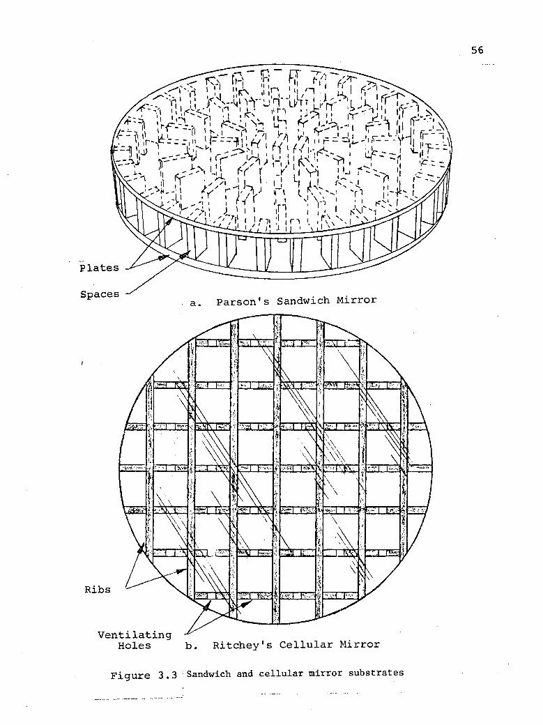
H o l e s b . R i t c h e y ' s C e l l u l a r M i r r o r
F i g u r e 3.3 Sandwich and c e l l u l a r m i r r o r substrates
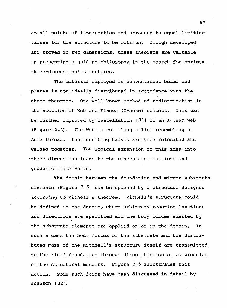
57
a t a l l p o i n t s o f i n t e r s e c t i o n and s t r e s s e d to e q u a l l i m i t i n g
v a l u e s f o r the s t r u c t u r e t o be optimum. Though deve loped
and proved i n two d i m e n s i o n s , these theorems are v a l u a b l e
i n p r e s e n t i n g a g u i d i n g p h i l o s o p h y i n the s e a r c h f o r optimum
t h r e e - d i m e n s i o n a l s t r u c t u r e s .
The m a t e r i a l employed i n c o n v e n t i o n a l beams and
p l a t e s i s not i d e a l l y d i s t r i b u t e d i n accordance w i t h the
above theorems. One wel l -known method o f r e d i s t r i b u t i o n i s
the a d o p t i o n o f Web and F lange (I-beam) c o n c e p t . T h i s can
be f u r t h e r improved by c a s t e l l a t i o n [31] o f an I-beam Web
(F igure 3 . 4 ) . The Web i s cut a l o n g a l i n e r e s e m b l i n g an
Acme t h r e a d . The r e s u l t i n g h a l v e s are then r e l o c a t e d and
welded t o g e t h e r . The l o g i c a l e x t e n s i o n o f t h i s i d e a i n t o
t h r e e d imens ions l eads t o the concepts o f l a t t i c e s and
g e o d e s i c frame works .
The domain between the f o u n d a t i o n and m i r r o r s u b s t r a t e
e lements (F igure 3.5) can be spanned by a s t r u c t u r e d e s i g n e d
a c c o r d i n g t o M i c h e l l ' s theorem. M i c h e l l ' s s t r u c t u r e c o u l d
be d e f i n e d i n the domain, where a r b i t r a r y r e a c t i o n l o c a t i o n s
and d i r e c t i o n s a re s p e c i f i e d and the body f o r c e s e x e r t e d by
the s u b s t r a t e e lements are a p p l i e d on or i n the domain. In
such a case the body f o r c e s o f the s u b s t r a t e and the d i s t r i
buted mass o f the M i t c h e l l ' s s t r u c t u r e i t s e l f are t r a n s m i t t e d
to the r i g i d f o u n d a t i o n through d i r e c t t e n s i o n o r compress ion
o f the s t r u c t u r a l members. F i g u r e 3.5 i l l u s t r a t e s t h i s
n o t i o n . Some such forms have been d i s c u s s e d i n d e t a i l by
Johnson [32] .
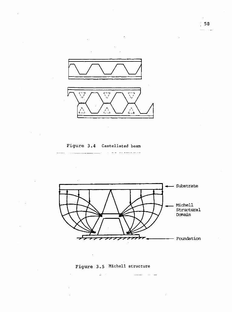
F i g u r e 3 . 4 C a s t e l l a t e d beam
F i g u r e 3 . 5 M i c h e l l s t r u c t u r e
59
The alternate approach to optimization follows from
Maxwell's o r i g i n a l theorem. By arranging the material i n
arch-like configurations, an optimum design i s l i k e l y to
r e s u l t , i n which the material tends to be stressed i n one
sense. Kenny [33] has demonstrated, by comparing deflections
of a disc to those of spherical s h e l l s , which may be con
structed by removing materials from the d i s c , that a s h e l l
or an arch type structure i s much superior to a constant
thickness plate.
In the present investigation the second l i n e of
thought i s pursued to optimize c i r c u l a r substrates having
superior stiffness-to-weight r a t i o s . I t was thought that
arch-type substrates would be less i n t r i c a t e than ribbed
sandwiches or spac i a l l a t t i c e s which r e f l e c t the philosophy
behind Michell's c o r o l l a r y to Maxwell's theorem.
F i n a l l y i t must be stressed that, the optimum
configuration changes with each change i n the attitude of
a mirror. Thus, there can be no unique optimum configuration
for a substrate which changes attitude i n a g r a v i t a t i o n a l
f i e l d . However, i t i s customary to design a substrate with
the axis of the mirror v e r t i c a l and to assume the demonstra-
table fact that deformation due to gravity i n p a r t i c u l a r
w i l l be less severe and not c r i t i c a l when the axis i s
horizon t a l .
Hence, as with other investigations, design studies
to follow are concerned with substrates having extreme
dimensions i n a plane normal to the v e r t i c a l .
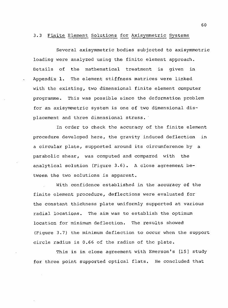
60
3.3' F i n i t e E l e m e n t S o l u t i o n s f o r A x i s y m m e t r i c Systems
S e v e r a l a x i s y m m e t r i c b o d i e s s u b j e c t e d t o a x i s y m m e t r i c
l o a d i n g were a n a l y z e d u s i n g t h e f i n i t e e l e m e n t a p p r o a c h .
D e t a i l s o f t h e m a t h e m a t i c a l t r e a t m e n t i s g i v e n i n
A p p e n d i x 1. The e l e m e n t s t i f f n e s s m a t r i c e s were l i n k e d
w i t h t h e e x i s t i n g , two d i m e n s i o n a l f i n i t e e l e m e n t computer
programme. T h i s was p o s s i b l e s i n c e t h e d e f o r m a t i o n p r o b l e m
f o r an a x i s y m m e t r i c s y s t e m i s one o f two d i m e n s i o n a l d i s
p l a c e m e n t and t h r e e d i m e n s i o n a l s t r e s s .
I n o r d e r t o c h e c k t h e a c c u r a c y o f t h e f i n i t e e l e m e n t
p r o c e d u r e d e v e l o p e d h e r e , t h e g r a v i t y i n d u c e d d e f l e c t i o n i n
a c i r c u l a r p l a t e , s u p p o r t e d a r o u n d i t s c i r c u m f e r e n c e b y a
p a r a b o l i c s h e a r , was computed and compared w i t h t h e
a n a l y t i c a l s o l u t i o n ( F i g u r e 3 . 6 ) . A c l o s e a g r e e m e n t b e
tween t h e two s o l u t i o n s i s a p p a r e n t .
W i t h c o n f i d e n c e e s t a b l i s h e d i n t h e a c c u r a c y o f t h e
f i n i t e e l e m e n t p r o c e d u r e , d e f l e c t i o n s were e v a l u a t e d f o r
t h e c o n s t a n t t h i c k n e s s p l a t e u n i f o r m l y s u p p o r t e d a t v a r i o u s
r a d i a l l o c a t i o n s . The a i m was t o e s t a b l i s h t h e optimum
l o c a t i o n f o r minimum d e f l e c t i o n . The r e s u l t s showed
( F i g u r e 3.7) t h e minimum d e f l e c t i o n t o o c c u r when t h e s u p p o r t
c i r c l e r a d i u s i s 0.66 o f t h e r a d i u s o f t h e p l a t e .
T h i s i s i n c l o s e a greement w i t h Emerson's [15] s t u d y
f o r t h r e e p o i n t s u p p o r t e d o p t i c a l f l a t s . He c o n c l u d e d t h a t

61
gure 3.6 The middle s u r f a c e d e f l e c t i o n as p r e d i c t e d by the f i n i t e e lement p rocedure and the a n a l y t i c a l s o l u t i o n : D
E = 10.5 x 1 0 6 ; v = 0 .17 ; p = 0.0795 ; g = 6
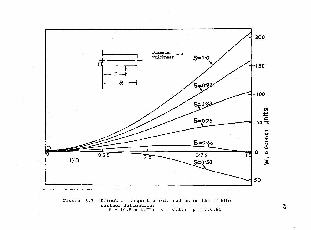
63
the t h r e e p o i n t s s h o u l d be l o c a t e d a t 0 .7a f o r the minimum bend
i n g d e f l e c t i o n . S t u d i e s conducted by Kenny and W i l l i a m s
[ 8 ] f and Vaughan [io] a l s o l e d t o the same c o n c l u s i o n .
With t h i s background i t was d e c i d e d t o p roceed w i t h the a rched
s u b s t r a t e a n a l y s i s .
3 . 3 . 1 Comparat ive A n a l y s i s o f Arched S t r u c t u r e s and S o l i d D i s c s
I t i s impor tan t to r e c o g n i z e t h a t i n d e s i g n i n g a
l i g h t we ight m i r r o r s u b s t r a t e , a r e l a t i v e l y h i g h e r s t i f f n e s s -
t o - w e i g h t r a t i o may be o b t a i n e d by removing m a t e r i a l s
t o form an a r c h from a deep s o l i d d i s c (D/H = 3) r a t h e r
than from a moderate ly t h i c k d i s c (D/H = 6 ) . But the space
o c c u p i e d by the former w i l l be l a r g e r than the l a t t e r . T h i s
i n t u r n w i l l need a l a r g e r h o u s i n g and s u p p o r t i n g s t r u c t u r e
f o r the m i r r o r . So, i n the s u b s t r a t e d e s i g n , the q u e s t i o n
o f space l i m i t a t i o n has to be borne i n mind . The s u b s t r a t e
forms a n a l y z e d i n the p r e s e n t s tudy are l i m i t e d w i t h i n the
space enve lope o f the c o n v e n t i o n a l s o l i d d i s c h a v i n g d iameter
to t h i c k n e s s r a t i o of 6. F u r t h e r m o r e , a s l i g h t c u r v a t u r e
o f the r e f l e c t i n g s u r f a c e i s n e g l e c t e d . As the o b j e c t i v e
i s t o compare d e f l e c t i o n - t o - w e i g h t r a t i o s r e s u l t i n g from
changes i n the geometry o f the m i r r o r s u b s t r a t e , the e r r o r
i n t r o d u c e d by t h i s approx imat ion i s l i k e l y to be i n s i g n i f i
c a n t .

6 4
Figure 3.8 shows the plate previously considered
with certain material removed so that the substrate proper
remains but an arch transmits i t s body weight to the outer
c i r c u l a r boundary. The structures were analyzed by the
f i n i t e element method, which c l e a r l y demonstrated the e f f e c t
of attendant r e d i s t r i b u t i o n of substrate material on the
f l e x u r a l d e f l e c t i o n patterns. The deflections of the
upper surface of these substrates are shown i n Figures 3.9 and
3.10. For comparison, the d e f l e c t i o n of the related s o l i d
d i s c i s also included. Ratios of the deflections of the
arch models to those of the s o l i d d i s c are plotted i n
Figures 3.11 and 3.12 together with the average d e f l e c t i o n
r a t i o s .
In designing mirror substrate one i s interested i n
achieving a low weight with high s t i f f n e s s . Thus i n determin
ing the merit of arched substrates compared to s o l i d discs,
a parameter involving both weight and d e f l e c t i o n i s desired.
For t h i s purpose a function c a l l e d 'figure of merit' has
been defined as the r a t i o of the product of weight and
de f l e c t i o n for the s o l i d disc to that for the arched sub
s t r a t e . Figure of merit values, based on the maximum
def l e c t i o n of the upper surface, for d i f f e r e n t arch models
are shown i n Table 3.1.
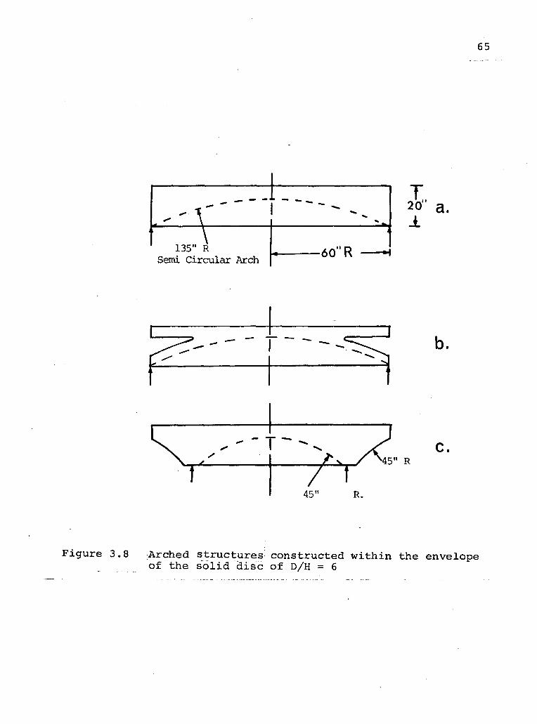
65
F i g u r e 3.8 Arched s t r u c t u r e s c o n s t r u c t e d w i t h i n the enve lope o f the s o l i d d i s c o f D/H = 6
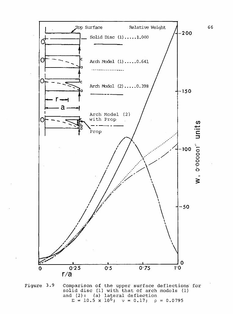
F i g u r e 3.9 Comparison o f the upper s u r f a c e d e f l e c t i o n s f o r s o l i d d i s c (1) w i t h t h a t o f a r c h models (1) and ( 2 ) : (a) l a t e r a l d e f l e c t i o n
E = 10.5 x 1 0 6 ; V = 0 . 1 7 ; p = 0.0795
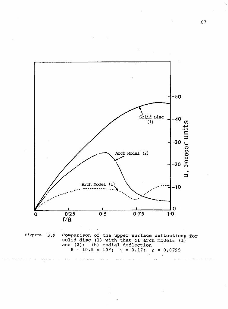
67
F i g u r e
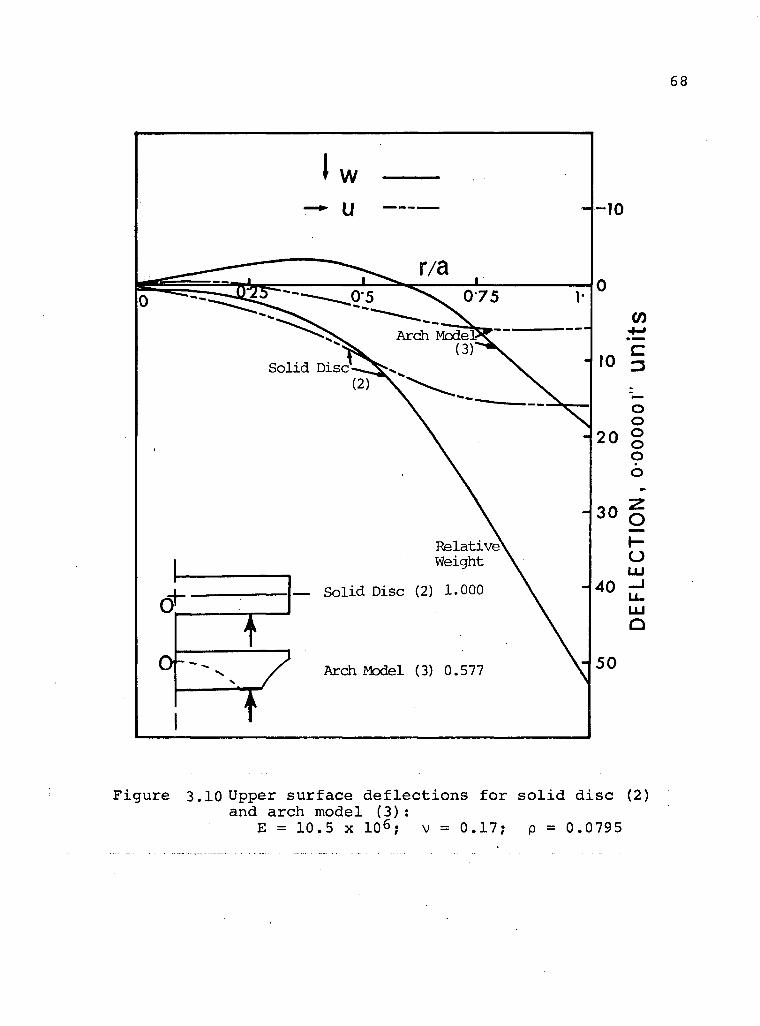
gure 3.10 Upper surface deflections for s o l i d disc (2) and arch model (3):
E = 10.5 x 10⁶; v = 0.17; p = 0.0795
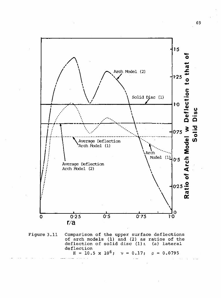
69
Arch Model (2)
1-5
O
(0
F i g u r e 3.11 Comparison o f the upper s u r f a c e d e f l e c t i o n s of a r c h models (1) and (2) as r a t i o s o f the d e f l e c t i o n o f s o l i d d i s c (1) :. (a) l a t e r a l d e f l e c t i o n
E = 10.5 x 1 0 6 ; v = 0 . 1 7 ; p = 0.0795

70
Sol id Disc (1)
Arch Model (2)
Average Deflection 'Arch Model (2) /
" 1 Arch Model (1)
Average Deflection Arch Model (1)
10 o
C 075-j?
o
Q
0 5 -
O
o 3 »
Q
•a
"5 (0
u <
O • warn
OS
r/a 02 5 0 5 0 7 5 10
F i g u r e 3 . H Comparison o f the upper s u r f a c e d e f l e c t i o n s o f a r ch models (1) and (2) as r a t i o s o f the d e f l e c t i o n o f s o l i d d i s c (1).: (b) r a d i a l d e f l e c t i o n
E = 10.5 x 1 0 6 ; v = 0 . 1 7 ; p = 0.0795

71
r/a Figure 3.12 Upper surface deflections of arch model (3)
as r a t i o s of the deflections of s o l i d d i s c (2): ,
E = 10.5 x 10 ; v = 0.17; p = 0.0795

72
A compar ison o f d e f l e c t i o n p a t t e r n s c l e a r l y
e s t a b l i s h e s the g r e a t p o t e n t i a l o f a r c h i n g i n d e s i g n i n g l i g h t
we ight m i r r o r s u b s t r a t e s . For r i n g suppor t r e a c t i o n s a t
S = 1, the maximum l a t e r a l d e f l e c t i o n w f o r the s o l i d d i s c
i s about two t imes h i g h e r than t h a t o f a r c h models (1) and
( 2 ) . On the o t h e r hand the we ight o f the s o l i d d i s c i s
35.9% and 60.2% h i g h e r than t h a t o f a rch models (1) and ( 2 ) ,
r e s p e c t i v e l y . In terms o f average d e f l e c t i o n r a t i o , the
a r c h models (1) and (2) o f f e r 29.7% and 17.6% r e d u c t i o n i n
w d e f l e c t i o n and the f i g u r e o f m e r i t v a l u e s are 2.84 and
4.6 8 , r e s p e c t i v e l y . For r i n g suppor t r e a c t i o n s a t S = 0 . 5 8 ,
the maximum w d e f l e c t i o n f o r the s o l i d d i s c i s about 2.8
t imes h i g h e r than t h a t of a rch model (3) whereas the we ight
o f the s o l i d d i s c i s 42.3% h i g h e r than t h a t o f a r c h model ( 3 ) .
C o n s i d e r i n g the average d e f l e c t i o n r a t i o , a r ch model (3) o f f e r s
50.39% r e d u c t i o n i n the w d e f l e c t i o n and the f i g u r e o f m e r i t
va lue i s 4 . 8 7 .
From above i t appears t h a t among the d i f f e r e n t
geometr ies c o n s i d e r e d , a r ch model (3) i s the most
advantageous .
I t s h o u l d be noted here t h a t f o r a s t r o n o m i c a l p u r
poses the changes i n s l o p e and c u r v a t u r e o f the r e f l e c t i n g
s u r f a c e o f the m i r r o r are o f the main i n t e r e s t . These parameters
b e i n g r e l a t e d to d e f l e c t i o n , the p r e s e n t a n a l y s i s i s q u i t e
r e p r e s e n t a t i v e o f the t r u e s i t u a t i o n .
F i g u r e 3.9 suggests t h a t the overhang ing type sub-
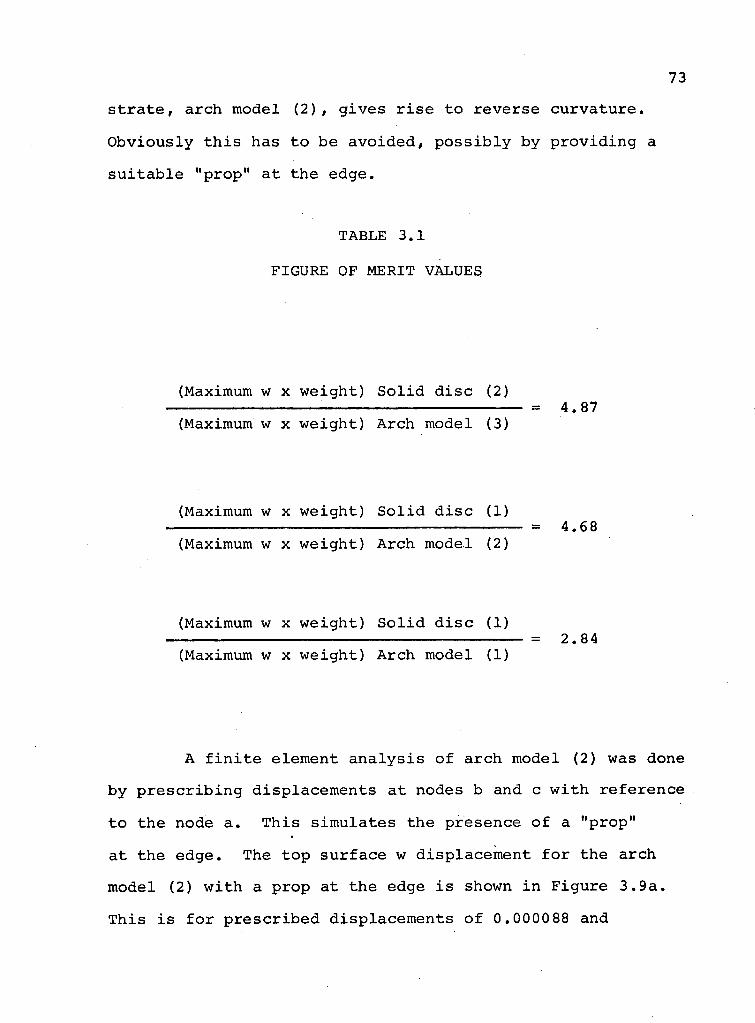
s t r a t e , a rch model ( 2 ) , g i v e s r i s e to r e v e r s e c u r v a t u r e .
O b v i o u s l y t h i s has t o be a v o i d e d , p o s s i b l y by p r o v i d i n g a
s u i t a b l e "prop" a t the edge.
TABLE 3.1
FIGURE OF MERIT VALUES
(Maximum w x weight) S o l i d d i s c (2)
(Maximum w x weight) Arch model (3)
(Maximum w x weight) S o l i d d i s c (1)
(Maximum w x weight) A rch model (2)
(Maximum w x weight) S o l i d d i s c (1)
(Maximum w x weight) A rch model (1)
= 4.87
= 4.68
= 2.84
A f i n i t e e lement a n a l y s i s o f a r c h model (2) was done
by p r e s c r i b i n g d i s p l a c e m e n t s a t nodes b and c w i t h r e f e r e n c e
t o the node a . T h i s s i m u l a t e s the presence o f a "prop"
a t the edge. The top s u r f a c e w d i s p l a c e m e n t f o r the a rch
model (2) w i t h a prop at the edge i s shown i n F i g u r e 3 . 9 a .
T h i s i s f o r p r e s c r i b e d d i s p l a c e m e n t s o f 0.0000 88 and
74
0.000112 i n . a t the nodes b and c , r e s p e c t i v e l y . The d i s
p lacement o f c r e l a t i v e t o a i s 0.000710 i n . when t h e r e i s
no "prop" (arch model ( 2 ) ) , and 0.000011 i n . when t h e r e i s
no " h o l e , " (arch model ( 1 ) ) . Thus the a n a l y s i s w i t h
s p e c i f i e d d i s p l a c e m e n t o f 0.000112 i n . r e p r e s e n t s a
s i t u a t i o n between a rch models (1) and ( 2 ) . The a n a l y s i s
demonstrates the p r i n c i p l e t h a t the r e v e r s e c u r v a t u r e o f
a r c h model (2) can be a v o i d e d by p r o v i d i n g a "prop" a t the
edge. The exac t na tu re o f the d i s p l a c e m e n t s w i l l be governed
by the s i z e o f the " p r o p " .
The geometr ies s t u d i e d here were s e l e c t e d t o
demonstrate the p r i n c i p l e o f a r ch a c t i o n r a t h e r than e s t a b
l i s h i t s optimum shape. The s tudy was i n i t i a t e d w i t h a
s imp le s e m i - c i r c u l a r a r c h , so t h a t d u r i n g e x p e r i m e n t a l
i n v e s t i g a t i o n the model can be e a s i l y machined.
Arch model (3) i s the b e s t among the c o n f i g u r a
t i o n s s t u d i e d . T h i s i s because the suppor t r e a c t i o n s are
p r o v i d e d c l o s e to the c e n t r e o f g r a v i t y . A l s o , the f l e x u r e
o f the overhang i s reduced by removing i t s m a t e r i a l i n an
a r c h - l i k e manner.
A comment c o n c e r n i n g the C a s s e g r a i n i a n s u b s t r a t e ,
which was a n a l y z e d by the f i n i t e e lement method would be
a p p r o p r i a t e . I t s top s u r f a c e d e f l e c t i o n f o r d i f f e r e n t suppor t
c i r c l e r a d i i i s shown i n F i g u r e 3 .13 . I t i s e v i d e n t t h a t ,
f o r the geometr ies s t u d i e d , the minimum d e f l e c t i o n i s o b t a i n e d
f o r a v a l u e o f S l y i n g between 0.75 and 0 . 6 6 .
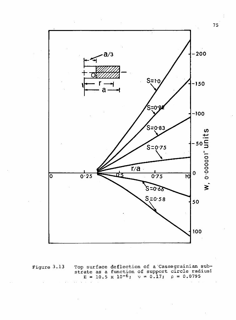
Figure 3.13 Top surface d e f l e c t i o n of a Cassegrainian substrate as a function of support c i r c l e radius:
E = 1 0 . 5 x 1 0 - 6 ; v = 0 . 1 7 ; p = 0 . 0 7 9 5
3.3.2 D e f l e c t i o n Due t o T h e r m a l G r a d i e n t
The d e f o r m a t i o n o f a m i r r o r s u r f a c e due t o t h e r m a l
e f f e c t s ( c h a n g e s i n a m b i e n t t e m p e r a t u r e o r p r e s e n c e o f
t h e r m a l g r a d i e n t s ) i s o f u t m o s t i m p o r t a n c e as i t may e x c e e d
t h e t o l e r a n c e l i m i t s o f d i f f r a c t i o n , l i m i t e d o p t i c s .
I t i s p o s s i b l e t o t r e a t t h e r m a l e f f e c t s b y t h e same
f i n i t e e l e m e n t programme a s t h a t d e v e l o p e d f o r b o d y f o r c e
l o a d e d a x i s y m m e t r i c s o l i d s . T h e r m a l e f f e c t s c a n be i n c l u d e d
i n t h e c a l c u l a t i o n s d i r e c t l y b y a c c o u n t i n g f o r c o r r e s p o n d i n g
s t r a i n s i n e a c h e l e m e n t w h i l e w r i t i n g t h e s t r e s s - s t r a i n
r e l a t i o n s i n v o l v e d . T h i s l e a d s t o an a d d i t i o n a l t e r m i n
t h e f o r c e - d i s p l a c e m e n t r e l a t i o n . The a d d i t i o n a l t e r m
r e p r e s e n t s t h e t h e r m a l f o r c e w h i c h a c t s a t e v e r y node a n d h e n c e
a p p e a r s i n t h e f i n a l l o a d m a t r i x o f t h e w h o l e s t r u c t u r e .
The e v a l u a t i o n o f t h e r m a l d i s p l a c e m e n t s i s b r i e f l y d i s c u s s e d
i n A p p e n d i x 2.
The f i n i t e e l e m e n t programme d e v e l o p e d f o r t h e d i s
p l a c e m e n t a n a l y s i s o f b o d y - f o r c e l o a d e d a x i s y m m e t r i c s o l i d s
was m o d i f i e d t o a c c o u n t f o r any t h e r m a l e f f e c t . The
m o d i f i e d programme c a l c u l a t e s t h e r m a l l y i n d u c e d n o d a l f o r c e s
by u s i n g t h e r e l a t i o n s h i p ( A 2 . 4 ) .
T h e r m a l d e f l e c t i o n s w e r e c a l c u l a t e d f o r a c y l i n d r i c a l
p l a t e s u b j e c t e d t o l i n e a r t e m p e r a t u r e g r a d i e n t T ( z ) = Kz ,
w h e r e K i s a c o n s t a n t . The d e f l e c t i o n p l o t s a r e p r e s e n t e d
i n F i g u r e s 3.14 and 3.15 N o t e t h a t t h e t o p a n d b o t t o m
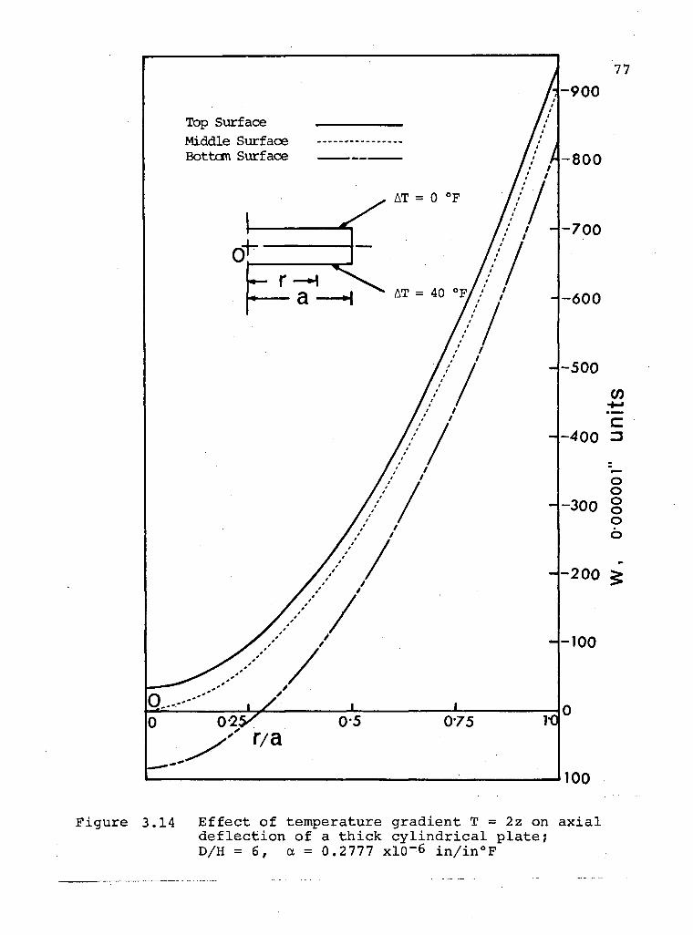
100
Figure 3.14 E f f e c t of temperature gradient T = 2z on a x i a l d e f l e c t i o n of a thick c y l i n d r i c a l plate; D/H =6, a = 0.2777 xl0~6 in/in°F

78
F i g u r e 3.15 R a d i a l d e f l e c t i o n i n a t h i c k c y l i n d r i c a l p l a t e due t o a temperature g r a d i e n t T = 2 z ;
a = 0.2777 x I O - 6 in/in°F

s u r f a c e s o f the p l a t e assume d i f f e r e n t shapes . T h i s i s due
to the f a c t t h a t , i n the example , the top s u r f a c e undergoes
a temperature change o f 0°F as a g a i n s t the bottom s u r f a c e
temperature change o f 40°F. Fo r a p lane d i s c , a n a b s o l u t e
temperature change w i l l no t induce any v a r i a t i o n i n the
c u r v a t u r e , but i f s u r f a c e s are c u r v e d , a b s o l u t e temperature
change may modi fy the c u r v a t u r e .
I t s h o u l d be noted here t h a t the b o d y - f o r c e - i n d u c e d
d i s p l a c e m e n t i n a s u b s t r a t e f o r a p a r t i c u l a r l o a d i n g i s
c o n s t a n t , but t h a t due t o the rma l e f f e c t s w i l l depend on the
magnitude o f the temperature change. A compar ison o f the
l a t e r a l d e f l e c t i o n s ( F i g u r e s 3 . 6 , 3 . 1 4 ) shows t h a t a the rma l
g r a d i e n t o f 2°F/inch can induce d i s p l a c e m e n t s more than f o u r
t imes those due to g r a v i t y . The importance o f e q u a l i z i n g
the temperature w i t h i n a t e l e s c o p e dome-enc losure i s thus
q u i t e a p p a r e n t .

4 . EXPERIMENTAL TECHNIQUES FOR THE ANALYSIS OF BODY' FORCE DEFLECTION
The p r e s e n t p r o j e c t i s e s s e n t i a l l y t h e o r e t i c a l i n
c h a r a c t e r . However, i t was thought a p p r o p r i a t e t o undertake
e x p e r i m e n t a l s t u d i e s to s u b s t a n t i a t e the t h e o r e t i c a l
p r e d i c t i o n s o f r e d u c t i o n i n the weight t o s t i f f n e s s r a t i o
f o r m i r r o r s u b s t r a t e s by removing m a t e r i a l s i n a r c h - l i k e
manner.
E x p e r i m e n t a l i n v e s t i g a t i o n o f body f o r c e induced
d i s p l a c e m e n t s i n a model p r e s e n t s c o n s i d e r a b l e d i f f i c u l t y .
G r a v i t y induced d i s p l a c e m e n t s a r e , i n g e n e r a l , s m a l l and
d i m i n i s h f u r t h e r i n p r o p o r t i o n to the l i n e a r s c a l e o f the
mode l . Thus the e x p e r i m e n t a l t e c h n i q u e s used are r e q u i r e d to
have s u f f i c i e n t r e s o l u t i o n to i d e n t i f y low o r d e r s t r e s s e s
o r d i s p l a c e m e n t s .
4 .1 Review o f the E x p e r i m e n t a l S t u d i e s f o r M i r r o r S u b s t r a t e
S e v e r a l i n v e s t i g a t o r s have conducted e x p e r i m e n t a l
s t u d i e s o f s e l f - w e i g h t d e f l e c t i o n o f m i r r o r s u b s t r a t e s .
Emerson [15] determined t r u e c o n t o u r s ( i . e . , c o n t o u r s o f
u n i f o r m l y suppor ted p l a t e s i n absence o f bending) and the
bending d e f l e c t i o n cu rves f o r 10 5/8 i n c h d iameter o p t i c a l
81
f l a t s o f f used q u a r t z . Based on the r e l a t i o n s h i p t h a t the
bend ing d e f l e c t i o n v a r i e s i n v e r s e l y as the square o f the t h i c k
n e s s , the t r u e contours were o b t a i n e d by u s i n g t h r e e o p t i c a l
f l a t s o f l i k e m a t e r i a l , p r o p e r t i e s and d i a m e t e r . The p l a t e s
were t e s t e d i n p a i r s , a r ranged p a r a l l e l t o each o t h e r and
r e s t i n g , a t the v e r t i c e s o f an e q u i l a t e r a l t r i a n g l e , ove r
two s e t s o f suppor t s l o c a t e d one over the o t h e r . The
a l g e b r a i c sum o f con t our s o f the s u r f a c e s was determined
a long a d i a m e t r i c l i n e , p a r a l l e l t o two o f the s u p p o r t s ,
u s i n g a P u l f r i c h v i e w i n g i ns t rument [ 3 5 ] . The t e c h n i q u e
g i v e s q u i t e a c c u r a t e r e s u l t s but i s r e s t r i c t e d t o m i r r o r
s u b s t r a t e s i n the form of a s o l i d d i s c .
In t h i s l i n e o f s t u d i e s the s t e r e o s c o p i c approach due
to Gates [36]shou ld be ment ioned . The method r e l i e s on
the use of two i n t e r f e r o g r a m s i n which the ang le between
the i n t e r f e r i n g s u r f a c e s i s o f o p p o s i t e s i g n , bu t the
s p a c i n g and p o s i t i o n o f the f r i n g e s a r e , as f a r as the
i r r e g u l a r i t i e s o f the s u r f a c e s w i l l a l l o w , the same. The
r e l a t i v e d i s p l a c e m e n t s o f the bands a t c o r r e s p o n d i n g p o i n t s
o f each o f the p a i r o f i n t e r f e r o g r a m s are then measured
w i t h a double m i c r o s c o p e . The t e c h n i q u e a l l o w s measurement
o f d i s p l a c e m e n t s w i t h a s e n s i t i v i t y b e t t e r than 0.00 2 wave
l e n g t h . An i m p r e s s i o n o f the r e l i e f o f the s u r f a c e may a l s o
be o b t a i n e d by v i e w i n g the i n t e r f e r o g r a m s i n a s u i t a b l e
s t e r e o s c o p e .
Dew [37, 38] d e s c r i b e d a p r e c i s e method o f d e t e r m i n i n g
g r a v i t a t i o n a l sag and u n d e f l e c t e d f i g u r e o f o p t i c a l f l a t s

82
u s i n g a F i z e a u i n t e r f e r o m e t e r . The u n d e f l e c t e d c o n f i g u r a t i o n
o f a f l a t was determined by t a k i n g the mean o f the 1 f a c e up
f i g u r e 1 and ' f a c e down f i g u r e . 1 The g r a v i t a t i o n a l sag
was o b t a i n e d by measur ing f i r s t l y the f i g u r e o f the f l a t i n
the manner under i n v e s t i g a t i o n and second ly the u n d e f l e c t e d
f i g u r e by the method d e s c r i b e d above. The t e c h n i q u e g i v e s
q u i t e a c c u r a t e r e s u l t s but i s r e s t r i c t e d to s u b s t r a t e s i n
the form o f s o l i d d i s c s o n l y .
Unwin [ 3 9 ] has e s t a b l i s h e d a t e c h n i q u e o f measur ing
a c c e n t u a t e d g r a v i t a t i o n a l d e f o r m a t i o n s i n m i r r o r s u b s t r a t e
models by u s i n g Shadow Mo i re t e c h n i q u e . The a c c e n t u a t i o n o f
g r a v i t a t i o n a l d e f o r m a t i o n s was o b t a i n e d by immersing
p o l y u r e t h a n e foam models i n w a t e r . T h i s r e s u l t e d i n a
s u f f i c i e n t number of w e l l - d e f i n e d f r i n g e s to make a n a l y s i s
p o s s i b l e .
The i n v e s t i g a t i o n by Kenny [ 6 ] though e x p l o r a t o r y
i n na tu re shou ld a l s o be ment ioned . He conducted measure
ments o f f r o z e n d i s p l a c e m e n t s on p h o t o e l a s t i c models o f
m i r r o r s u b s t r a t e s . For t h i n p l a t e s , the t h e o r e t i c a l and
e x p e r i m e n t a l r e s u l t s showed good agreement. However, the
t h i c k p l a t e r e s u l t s e x h i b i t e d c o n s i d e r a b l e d i s c r e p a n c y .
A l s o , the t e s t s d a t a f o r two s i m i l a r t h i c k p l a t e s showed
c o n s i d e r a b l e v a r i a t i o n . The d i s c r e p a n c i e s may be a t t r i b u t e d
to u n r e l i a b l e e x p e r i m e n t a l t e c h n i q u e s and , p o s s i b l y , t o
d i f f e r e n t case h i s t o r i e s o f the mode ls .

83
4.2 Present Experimental Investigations
4 . 2 . 1 Frozen stress p h o t o e l a s t i c i t y coupled with the immersion analogy for g r a v i t a t i o n a l stresses
The frozen stress technique of ph o t o e l a s t i c i t y r e l i e s
on the a b i l i t y of epoxy resins to re t a i n at room temperature
a r e l a t i v e l y large e l a s t i c s t r a i n system induced at a higher
temperature when a suitable temperature cycle i s used
[ 4 0 - 4 2 ] . The technique of "locking" deformations due to
an applied load can be explained by means of the bi-phase
theory. The materials consist of long chain hydrocarbon
molecules, some of which are well bonded together by primary
bonds, whereas a large mass of them are less s o l i d l y held
through shorter secondary bonds. The properties of the
primary bonds do not change appreciably with temperature
whereas the secondary bonds become viscous as the temperature
increases. When a load i s applied at a high temperature the
viscous component carr i e s a very small portion of the loading
(corresponding to i t s low modulus of e l a s t i c i t y ) , the main
portion of the load being car r i e d by the primary bonds. If
the temperature i s lowered gradually to room temperature
while the load i s being maintained, the secondary bonds
become r i g i d again and "locks" the deformation of the primary
bonds. On removal of the load at room temperature the
primary bonds relax to a very small degree, but the main
portion of the deformation i s not recovered. As the "locking"
84
t a k e s p l a c e on a m i c r o s c o p i c s c a l e , the d e f o r m a t i o n and the
accompanying b i r e f r i n g e n c e i s m a i n t a i n e d i n a s l i c e o b t a i n e d
by c a r e f u l sawing o f the mode l , a v o i d i n g the g e n e r a t i o n o f
a p p r e c i a b l e h e a t .
The s l i c e thus o b t a i n e d from a t h r e e d i m e n s i o n a l model
can then be examined under the p o l a r i s c o p e l i k e a two
d i m e n s i o n a l mode l .
As ment ioned e a r l i e r , t h e main d i f f i c u l t y i n the
e x p e r i m e n t a l s tudy of body f o r c e problems i s the low s t r e s s
l e v e l induced i n models much s m a l l e r i n s i z e than the p r o t o
t y p e s . T h i s low s e n s i t i v i t y can be overcome by immersing
the model i n a l i q u i d o f h i g h d e n s i t y . The ana logy was
f i r s t shown by B i o t [ 4 3 ] f o r two d i m e n s i o n a l b o d i e s and by
S e r a f i m and Da C o s t a [ 4 4 ] f o r the t h r e e d i m e n s i o n a l c a s e . I t was
deve loped w i t h the assumpt ion t h a t the r a t i o o f the d e n s i t y
of the model t o the d e n s i t y o f the f l u i d was s m a l l enough
so t h a t the s t r e s s e s due to the former are n e g l i g i b l e [ 4 2 ] .
But f o r a c c u r a t e a n a l y s i s the weight o f the model s h o u l d
be taken i n t o a c c o u n t . T h i s was accomp l i shed by Parks e t a l .
[ 4 5 ] . The schemat ic p r o o f o f the immersion ana logy i s shown
i n F i g . 4 . 1 . I t i s c l e a r t h a t the advantage o f immersing
the model i n a heavy l i q u i d i s to i n c r e a s e the response o f
the model by ( K - l ) , where K i s the r a t i o o f the d e n s i t y o f
the l i q u i d i n which the model i s immersed to the d e n s i t y o f
the model m a t e r i a l .

F R E E B O D Y D I A G R A M
LOADING CONDITIONS
0. Boundary Condition*
b. Body Force*
S T R E S S S Y S T E M
L iquid Surface - j
r „ = o
R = reocl ions
b.
f \ r „ = o
R = reocl ions
b.
Liquid Sur face 0. < V - k y y
V O
b.
Y = k /
c t ^ - k / y
•M v » = 0
B.
i< . >\
•u ~-\
i
0. < V - k y y
V O
b.
Y = k /
c t ^ - k / y
•M v » = 0
C.
0. On=0
R = reaction*
b.
Y = - ( k - i ) r Is/)3 r*
D. "K^T"?' "i
a- o- n=o
- J — p = react ions k - l
b.
A. B o d y of density y submerged in a liquid of greater density k y .
B. B o d y , of density k y submerged in a liquid of It* own d e n s i t y .
C. Di f ference of above two , multiple gravi ty .
D. Gravity
4 1 Immersion analogy for g r a v i t a t i o n a l stresses [45]
86
In o r d e r t o o b t a i n the maximum a c c e n t u a t i o n o f
g r a v i t a t i o n a l s t r e s s e s mercury was used as the immersion
l i q u i d . In the s t r e s s f r e e z i n g p rocedure the model immersed
i n mercury has to b e . r a i s e d t o a temperature o f the o r d e r
o f 140°C. T h i s would g i v e r i s e t o some mercury v a p o u r , as
the b o i l i n g p o i n t o f mercury i s 180°C. As mercury vapour
i s r e a d i l y absorbed v i a r e s p i r a t o r y t r a c t and has adverse
e f f e c t s on the human body, arrangements were made i n d e s i g n
i n g immersion tank t o p i p e out the vapour and condense i t
i n a t e s t tube h e l d i n l i q u i d n i t r o g e n ( F i g . 4 .2).
The t h r e e - p o i n t suppor ted s o l i d d i s c m i r r o r s u b s t r a t e
and the c a l i b r a t i o n d i s c were loaded i n an oven . The
temperature was r a i s e d a t the r a t e o f 1°C per hour t o
140°C. A f t e r 48 hours a t 140°C, the temperature was lowered
at the r a t e o f 1°C per pour t o room t e m p e r a t u r e . A t the end
o f the l o a d i n g c y c l e the model was removed from the oven and
the d e s i r e d s l i c e s were cu t f o r e x a m i n a t i o n , u s i n g a
diamond impregnated s l i t t i n g wheel w i t h cop ious amount o f
l i q u i d c o o l a n t .
Though a c c e n t u a t i o n o f g r a v i t y i nduced s t r e s s e s was
a c h i e v e d by immersion o f the model i n mercury , i n o r d e r t o
improve the a c c u r a c y and t o i d e n t i f y low o r d e r f r a c t i o n a l
f r i n g e s i t was n e c e s s a r y t o use f r i n g e m u l t i p l i c a t i o n . The
n o v e l f r i n g e m u l t i p l i c a t i o n t e c h n i q u e due t o P o s t [46, 47]
was used i n the e v a l u a t i o n o f p h o t o e l a s t i c r e s u l t s .
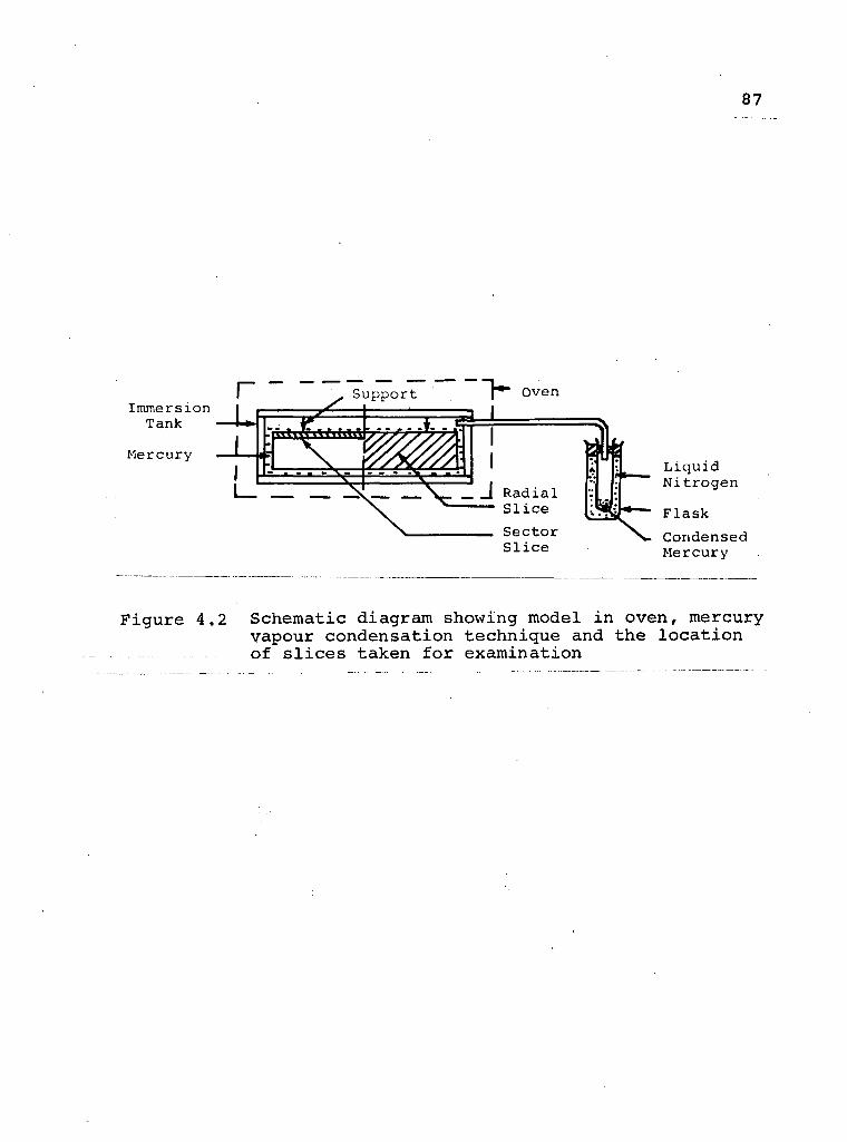
8 7
Figure 4 . 2 Schematic diagram showing model i n oven, mercury vapour condensation technique and the location of s l i c e s taken for examination
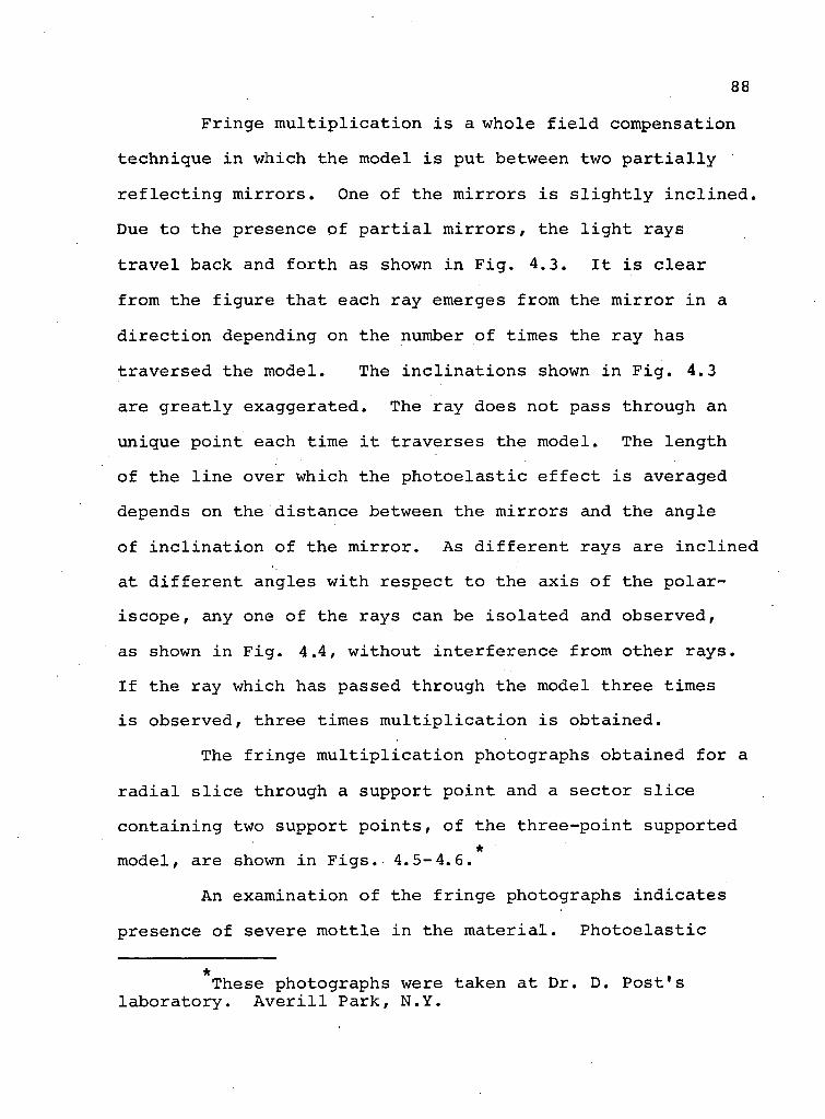
88
F r i n g e m u l t i p l i c a t i o n i s a whole f i e l d compensat ion
t e c h n i q u e i n which the model i s put between two p a r t i a l l y
r e f l e c t i n g m i r r o r s . One o f the m i r r o r s i s s l i g h t l y i n c l i n e d .
Due to the presence o f p a r t i a l m i r r o r s , the l i g h t rays
t r a v e l back and f o r t h as shown i n F i g . 4.3. I t i s c l e a r
from the f i g u r e t h a t each ray emerges from the m i r r o r i n a
d i r e c t i o n depending on the number o f t imes the r a y has
t r a v e r s e d the mode l . The i n c l i n a t i o n s shown i n F i g . 4.3
are g r e a t l y e x a g g e r a t e d . The ray does not pass through an
unique p o i n t each t ime i t t r a v e r s e s the model . The l e n g t h
o f the l i n e over which the p h o t o e l a s t i c e f f e c t i s averaged
depends on the d i s t a n c e between the m i r r o r s and the ang le
o f i n c l i n a t i o n o f the m i r r o r . As d i f f e r e n t rays are i n c l i n e d
at d i f f e r e n t ang les w i t h r e s p e c t t o the a x i s o f the p o l a r -
i s c o p e , any one o f the r a y s can be i s o l a t e d and o b s e r v e d ,
as shown i n F i g . 4.4, w i t h o u t i n t e r f e r e n c e from o t h e r r a y s .
I f the ray which has passed through the model t h r e e t imes
i s o b s e r v e d , t h r e e t imes m u l t i p l i c a t i o n i s o b t a i n e d .
The f r i n g e m u l t i p l i c a t i o n photographs o b t a i n e d f o r a
r a d i a l s l i c e through a suppor t p o i n t and a s e c t o r s l i c e
c o n t a i n i n g two suppor t p o i n t s , o f the t h r e e - p o i n t suppor ted *
model , are shown i n F i g s . 4 . 5 - 4 . 6 .
An examina t ion o f the f r i n g e photographs i n d i c a t e s
p resence o f severe m o t t l e i n the m a t e r i a l . P h o t o e l a s t i c *
These photographs were taken a t Dr . D. P o s t ' s l a b o r a t o r y . A v e r i l l P a r k , N.Y.
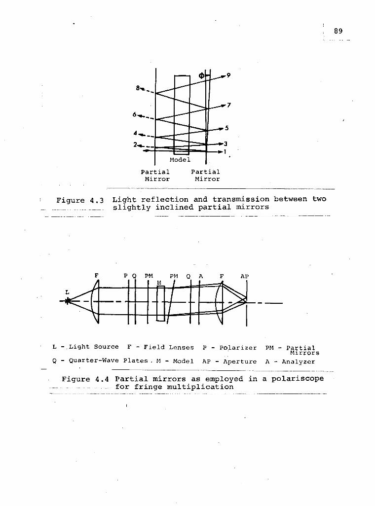
M o d e l
P a r t i a l M i r r o r
P a r t i a l M i r r o r
Figure 4.3 Light r e f l e c t i o n and transmission between two _._ s l i g h t l y i n c l i n e d p a r t i a l mirrors
p Q PM PM Q A
L i g h t S o u r c e F - F i e l d L e n s e s P - P o l a r i z e r PM - P a r t i a l M i r r o r s
Q u a r t e r - W a v e P l a t e s . M - M o d e l A P - A p e r t u r e A - A n a l y z e r
Figure 4.4 P a r t i a l mirrors as employed i n a polariscope for fringe m u l t i p l i c a t i o n
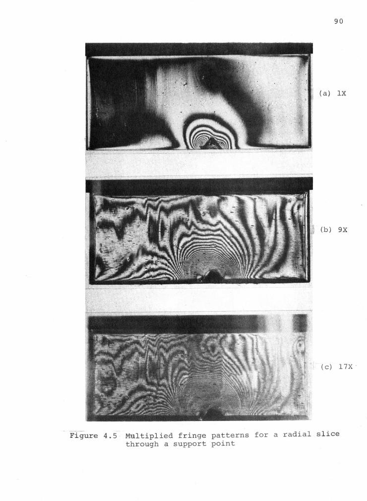
9 0
Figure 4 . 5 M u l t i p l i e d fringe patterns for a r a d i a l s l i c e through a support point
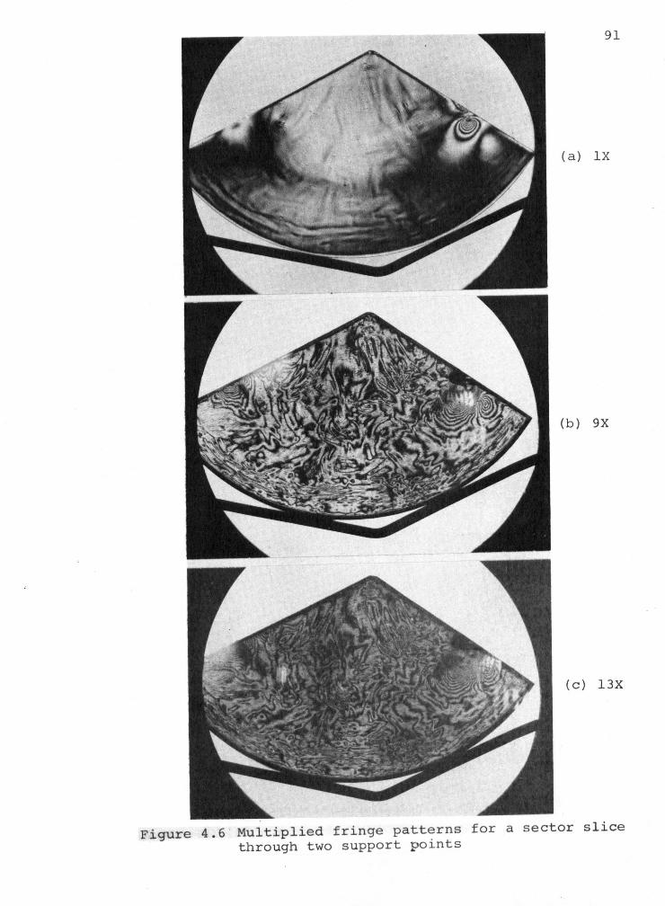
F i g u r e 4.6 M u l t i p l i e d f r i n g e p a t t e r n s through two suppor t p o i n t s
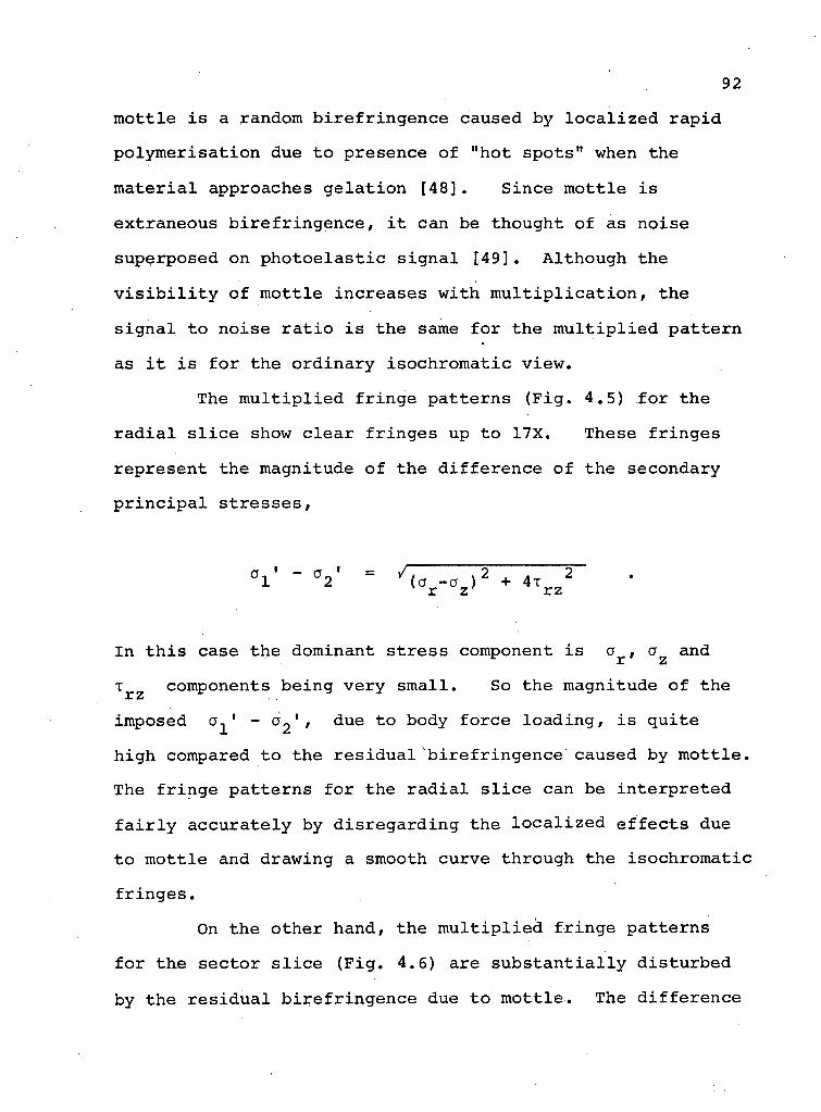
92
m o t t l e i s a random b i r e f r i n g e n c e caused by l o c a l i z e d r a p i d
p o l y m e r i s a t i o n due t o p resence o f "hot s p o t s " when the
m a t e r i a l approaches g e l a t i o n [ 4 8 ] . S i n c e m o t t l e i s
ex t raneous b i r e f r i n g e n c e , i t can be thought of as n o i s e
superposed on p h o t o e l a s t i c s i g n a l [ 4 9 ] . A l t h o u g h the
v i s i b i l i t y o f m o t t l e i n c r e a s e s w i t h m u l t i p l i c a t i o n , the
s i g n a l t o n o i s e r a t i o i s the same f o r the m u l t i p l i e d p a t t e r n
as i t i s f o r the o r d i n a r y i s o c h r o m a t i c v iew.
The m u l t i p l i e d f r i n g e p a t t e r n s ( F i g . 4.5) f o r the
r a d i a l s l i c e show c l e a r f r i n g e s up to 17X. These f r i n g e s
r e p r e s e n t the magnitude o f the d i f f e r e n c e o f the secondary
p r i n c i p a l s t r e s s e s ,
V - °2 = U c -a ) 2 + 4 x 2 ' r z r z
In t h i s case the dominant s t r e s s component i s a , a and
x r z components b e i n g v e r y s m a l l . So the magnitude o f the
imposed a^ 1 ~.°2% ' ^ u e t o kody f o r c e l o a d i n g , i s q u i t e
h i g h compared t o the r e s i d u a l b i r e f r i n g e n c e caused by m o t t l e .
The f r i n g e p a t t e r n s f o r the r a d i a l s l i c e can be i n t e r p r e t e d
f a i r l y a c c u r a t e l y by d i s r e g a r d i n g the l o c a l i z e d e f f e c t s due
t o m o t t l e and drawing a smooth curve through the i s o c h r o m a t i c
f r i n g e s .
On the o t h e r hand, the m u l t i p l i e d f r i n g e p a t t e r n s
f o r the s e c t o r s l i c e ( F i g . 4.6) a re s u b s t a n t i a l l y d i s t u r b e d
by the r e s i d u a l b i r e f r i n g e n c e due t o m o t t l e . The d i f f e r e n c e
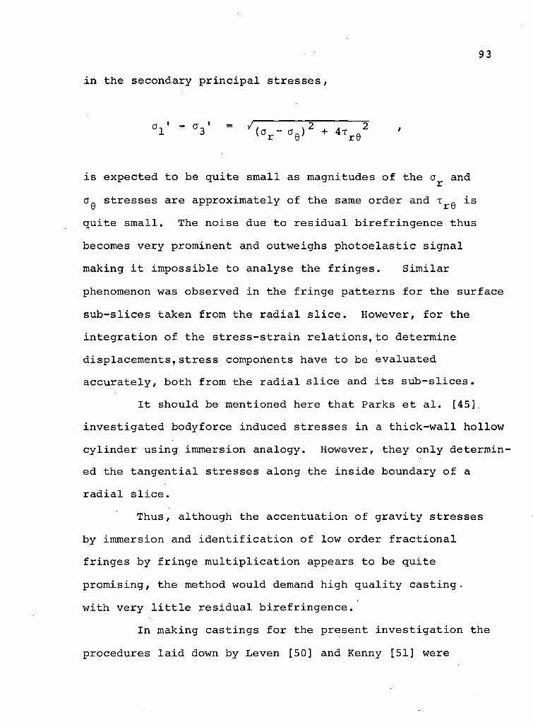
93
i n the secondary p r i n c i p a l s t r e s s e s ,
1 3 ( a r - a 0 ) + 4 T r Q
i s expec ted t o be q u i t e s m a l l as magnitudes o f the a and
oa s t r e s s e s a re a p p r o x i m a t e l y o f the same o r d e r and T Q i s u r t)
q u i t e s m a l l . The n o i s e due to r e s i d u a l b i r e f r i n g e n c e thus
becomes v e r y prominent and outweighs p h o t o e l a s t i c s i g n a l
making i t i m p o s s i b l e to a n a l y s e the f r i n g e s . S i m i l a r
phenomenon was observed i n the f r i n g e p a t t e r n s f o r the s u r f a c e
s u b - s l i c e s taken from the r a d i a l s l i c e . However, f o r the
i n t e g r a t i o n o f the s t r e s s - s t r a i n r e l a t i o n s , t o determine
d i s p l a c e m e n t s , s t r e s s components have t o be e v a l u a t e d
a c c u r a t e l y , bo th from the r a d i a l s l i c e and i t s s u b - s l i c e s .
I t s h o u l d be ment ioned here t h a t Parks e t a l . [45]
i n v e s t i g a t e d body fo rce induced s t r e s s e s i n a t h i c k - w a l l ho l l ow
c y l i n d e r u s i n g immersion a n a l o g y . However, they o n l y d e t e r m i n
ed the t a n g e n t i a l s t r e s s e s a l o n g the i n s i d e boundary o f a
r a d i a l s l i c e .
T h u s , a l though the a c c e n t u a t i o n o f g r a v i t y s t r e s s e s
by immers ion and i d e n t i f i c a t i o n o f low o r d e r f r a c t i o n a l
f r i n g e s by f r i n g e m u l t i p l i c a t i o n appears to be q u i t e
p r o m i s i n g , the method would demand h i g h q u a l i t y c a s t i n g ,
w i t h v e r y l i t t l e r e s i d u a l b i r e f r i n g e n c e .
In making c a s t i n g s f o r the p r e s e n t i n v e s t i g a t i o n the
p rocedures l a i d down by Leven [50] and Kenny [51] were
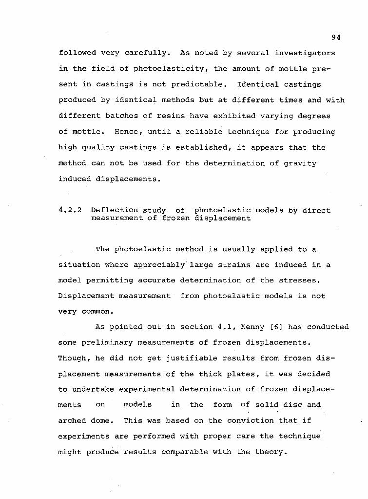
94
f o l l o w e d v e r y c a r e f u l l y . As noted by s e v e r a l i n v e s t i g a t o r s
i n the f i e l d o f p h o t o e l a s t i c i t y , the amount o f m o t t l e p r e
sent i n c a s t i n g s i s not p r e d i c t a b l e . I d e n t i c a l c a s t i n g s
produced by i d e n t i c a l methods but a t d i f f e r e n t t imes and w i t h
d i f f e r e n t ba tches o f r e s i n s have e x h i b i t e d v a r y i n g degrees
o f m o t t l e . Hence, u n t i l a r e l i a b l e t e c h n i q u e f o r p r o d u c i n g
h i g h q u a l i t y c a s t i n g s i s e s t a b l i s h e d , i t appears t h a t the
method can not be used f o r the d e t e r m i n a t i o n o f g r a v i t y
induced d i s p l a c e m e n t s .
4.2.2 D e f l e c t i o n study o f p h o t o e l a s t i c models by d i r e c t measurement o f f r o z e n d i s p l a c e m e n t
The p h o t o e l a s t i c method i s u s u a l l y a p p l i e d to a
s i t u a t i o n where a p p r e c i a b l y l a r g e s t r a i n s are induced i n a
model p e r m i t t i n g a c c u r a t e d e t e r m i n a t i o n o f the s t r e s s e s .
D i sp lacement measurement from p h o t o e l a s t i c models i s not
v e r y common.
As p o i n t e d out i n s e c t i o n 4 . 1 , Kenny [ 6 ] has conducted
some p r e l i m i n a r y measurements o f f r o z e n d i s p l a c e m e n t s .
Though, he d i d not get j u s t i f i a b l e r e s u l t s from f r o z e n d i s
p lacement measurements o f the t h i c k p l a t e s , i t was d e c i d e d
to undertake e x p e r i m e n t a l d e t e r m i n a t i o n o f f r o z e n d i s p l a c e
ments on models i n the form of s o l i d d i s c and
arched dome. T h i s was based on the c o n v i c t i o n t h a t i f
exper iments are per formed w i t h p roper c a r e the t e c h n i q u e
might produce r e s u l t s comparable w i t h the t h e o r y .
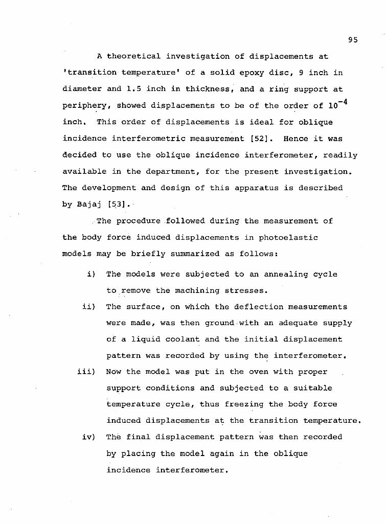
95
A t h e o r e t i c a l i n v e s t i g a t i o n o f d i s p l a c e m e n t s a t
• t r a n s i t i o n t e m p e r a t u r e 1 o f a s o l i d epoxy d i s c , 9 i n c h i n
d iameter and 1.5 i n c h i n t h i c k n e s s , and a r i n g suppor t a t
p e r i p h e r y , showed d i s p l a c e m e n t s t o be o f the o r d e r o f 10~ 4
i n c h . T h i s o r d e r o f d i s p l a c e m e n t s i s i d e a l f o r o b l i q u e
i n c i d e n c e i n t e r f e r o m e t r i c measurement [ 5 2 ] . Hence i t was
d e c i d e d to use the o b l i q u e i n c i d e n c e i n t e r f e r o m e t e r , r e a d i l y
a v a i l a b l e i n the department , f o r the p r e s e n t i n v e s t i g a t i o n .
The development and d e s i g n o f t h i s apparatus i s d e s c r i b e d
by B a j a j [ 5 3 ] .
The procedure f o l l o w e d d u r i n g the measurement o f
the body f o r c e induced d i s p l a c e m e n t s i n p h o t o e l a s t i c
models may be b r i e f l y summarized as f o l l o w s :
i ) The models were s u b j e c t e d to an a n n e a l i n g c y c l e
t o remove the mach in ing s t r e s s e s .
i i ) The s u r f a c e , on which the d e f l e c t i o n measurements
were made, was then ground-wi th an adequate supp ly
o f a l i q u i d c o o l a n t and the i n i t i a l d i s p l a c e m e n t
p a t t e r n was r e c o r d e d by u s i n g the i n t e r f e r o m e t e r ,
i i i ) Now the model was put i n the oven w i t h p roper
suppor t c o n d i t i o n s and s u b j e c t e d to a s u i t a b l e
temperature c y c l e , thus f r e e z i n g the body f o r c e
induced d i s p l a c e m e n t s a t the t r a n s i t i o n tempera ture .
i v ) The f i n a l d i s p l a c e m e n t p a t t e r n was then r e c o r d e d
by p l a c i n g the model aga in i n the o b l i q u e
i n c i d e n c e i n t e r f e r o m e t e r .

96
v) The body f o r c e induced d i s p l a c e m e n t was
deduced by s u b t r a c t i n g the i n i t i a l d i s p l a c e m e n t
from the f i n a l d i s p l a c e m e n t .
F o l l o w i n g t h i s p r o c e d u r e , the f r i n g e photographs f o r
the 'normal* and ' r e v e r s e ' l o a d i n g s were o b t a i n e d f o r the
d i s c w i t h r i n g suppor t a t the p e r i p h e r y ( F i g . 4 . 7 ) . C o r r e s
ponding d e f l e c t i o n s are p l o t t e d i n F i g . 4 . 8 , The i n t e r f e r o
grams r e p r e s e n t an a r e a i n the form o f an e l l i p s e , one i n c h
minor d iameter and n ine i n c h (d iameter o f the d i s c ) major
d i a m e t e r , compressed o p t i c a l l y i n t o a c i r c u l a r l y observed
f i e l d . I t i s apparent f rom F i g . 4.8 t h a t the d e f l e c t i o n
o b t a i n e d from the normal l o a d i n g show good agreement w i t h the
t h e o r y . On the o t h e r hand the non-symmetr ic d e f l e c t i o n
p a t t e r n o b t a i n e d from the r e v e r s e l o a d i n g shows c o n s i d e r a b l e
d i s c r e p a n c y . T h e o r e t i c a l l y , the normal and r e v e r s e l o a d i n g s
s h o u l d produce the same d e f l e c t i o n p a t t e r n s . T h i s r a i s e s
a doubt as t o the a p p l i c a b i l i t y o f the f r o z e n d i s p l a c e m e n t
t e c h n i q u e i n measur ing s e l f - w e i g h t d e f o r m a t i o n s .
Hence, i n s t e a d o f p u r s u i n g f u r t h e r i n v e s t i g a t i o n s
o f m i r r o r mode ls , i t was d e c i d e d t o conduct t e s t on a
s imp le beam t o g a i n more i n s i g h t i n t o t h i s a s p e c t o f the
p rob lem. The f r i n g e photographs f o r the s i m p l y suppor ted
beam are shown i n F i g u r e 4.9 and the d i s p l a c e m e n t s o b t a i n e d
are r e p r e s e n t e d i n F i g . 4 .10 . I t i s apparent t h a t d i s
p lacements a s s o c i a t e d w i t h normal and r e v e r s e l o a d i n g s are
q u i t e d i f f e r e n t from each o t h e r and show a g r e a t d i s c r e p a n c y
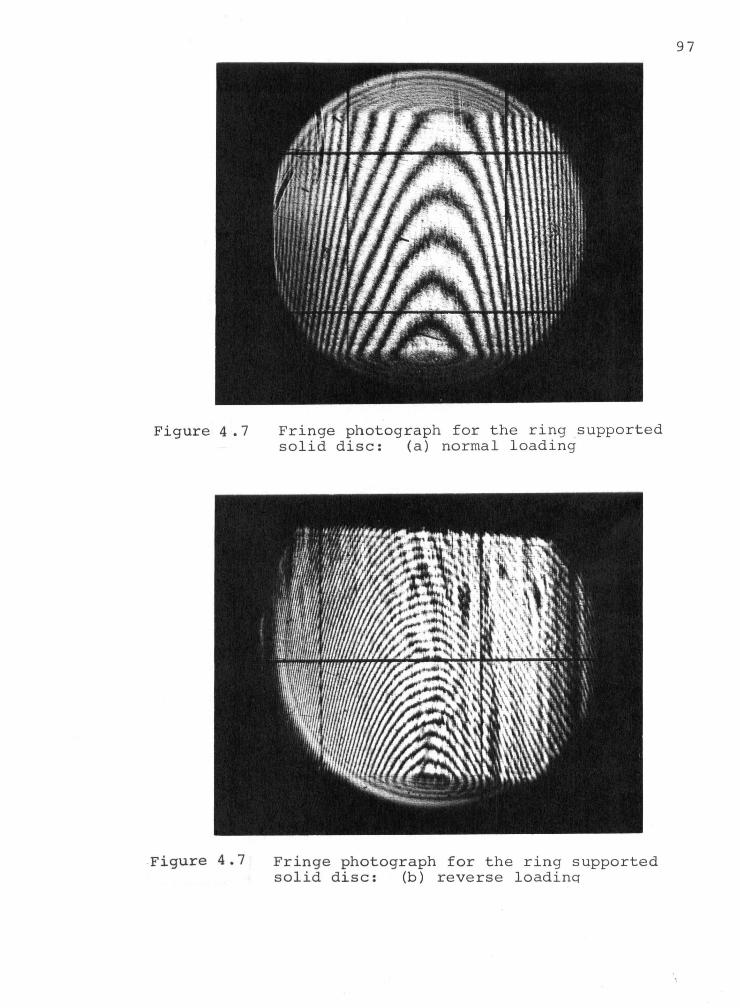
F i g u r e 4 . 7 F r i n g e photograph f o r the r i n g suppor ted s o l i d d i s c : (a) normal l o a d i n g
F i g u r e 4 . 7 F r i n g e photograph f o r the r i n g suppor ted s o l i d d i s c : (b) r e v e r s e l o a d i n g
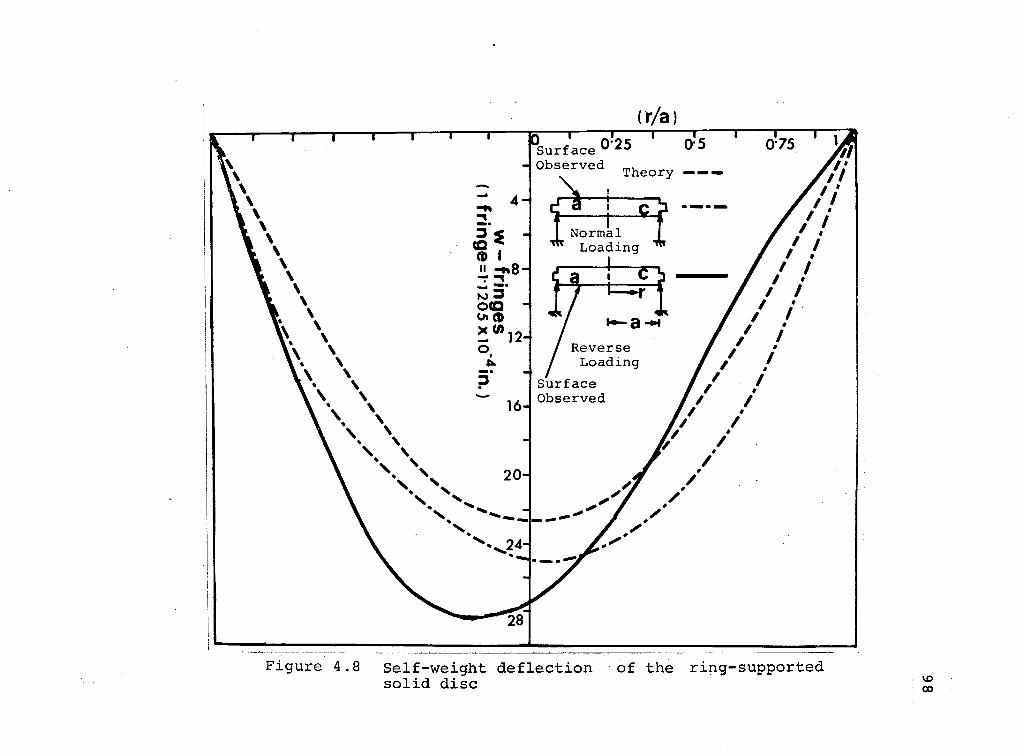
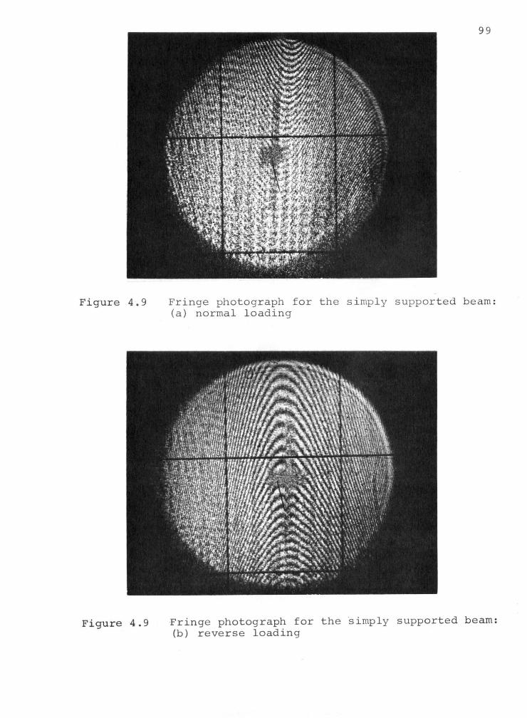
F i g u r e 4 . 9 F r i n g e photograph f o r t h e s i m p l y s u p p o r t e d beam: (a) normal l o a d i n g
F i g u r e 4 . 9 F r i n g e photograph f o r t h e s i m p l y s u p p o r t e d beam: (b) r e v e r s e l o a d i n g
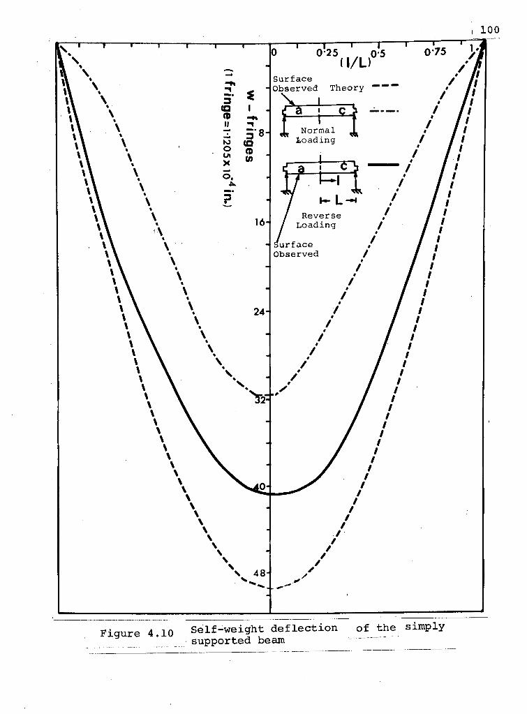
101 w i t h the t h e o r e t i c a l d i s p l a c e m e n t p a t t e r n . I t seems every
t ime the model undergoes a temperature c y c l e , some changes
take p l a c e i n the p h y s i c a l p r o p e r t i e s o f the epoxy
m a t e r i a l s .
The e x p e r i m e n t a l i n f o r m a t i o n a v a i l a b l e so f a r , though
not d i r e c t l y u s e f u l i n a c h i e v i n g the f i n a l o b j e c t i v e , p r o v i d e s
u s e f u l i n s i g h t i n t o the l i m i t a t i o n s o f epoxy models i n the
f r o z e n d i s p l a c e m e n t t e c h n i q u e . Some o f the impor tant
o b s e r v a t i o n s are l i s t e d below:
i ) I t seems t h a t every t ime the model undergoes
a therma l c y c l e the m a t e r i a l p r o p e r t y o f the
epoxy changes . T h i s c o u l d be due t o cont inuous
p o l y m e r i z a t i o n o f the model m a t e r i a l . I t seems
the p o l y m e r i z a t i o n i s never e n t i r e l y complete
though p h o t o e l a s t i c i a n s b e l i e v e t h a t by the
c u r i n g p r o c e s s the model m a t e r i a l i s r e n d e r e d
chemi c a l l y i n e r t .
i i ) As the exper iments were per formed i n the presence
o f a i r , the oxygen can r e a c t w i t h the polymer
groups and change the c h a r a c t e r i s t i c s o f the
model m a t e r i a l near the s u r f a c e . May be by
c o n d u c t i n g exper iments i n an i n e r t atmosphere
b e t t e r r e s u l t s c o u l d be o b t a i n e d ,
i i i ) F r oz en s t r e s s p h o t o e l a s t i c i t y i s a w e l l e s t a b
l i s h e d t e c h n i q u e . O p p e l , a p i o n e e r i n the f i e l d
o f p h o t o e l a s t i c i t y , has made d i s p l a c e m e n t

measurements on s l i c e s o b t a i n e d from t h r e e -
d i m e n s i o n a l p h o t o e l a s t i c mode ls . These were
f o r e x t e r n a l l y a p p l i e d loads where the d i s
p lacements produced by the l o a d i n g were f a r i n
excess o f d i s t u r b a n c e s due t o the c o n t i n u o u s
p o l y m e r i z a t i o n . However, f o r s e l f - w e i g h t loaded
systems the minute d i s p l a c e m e n t s are e a s i l y
out -weighed by these d i s t u r b a n c e s and/or r e a c t i o n s
o f the polymer groups w i t h the oxygen o f the
s u r r o u n d i n g atmosphere.
On the b a s i s o f Kenny 's exper iments w i t h t h i c k p l a t e s
and a s s o c i a t e d d i s c r e p a n c y w i t h the t h e o r y as ment ioned
b e f o r e (exper iments w i t h t h i n p l a t e s s u b s t a n t i a t e d the
t h e o r y ) , i t appears t h a t p o l y m e r i z a t i o n a l s o depends on
s u r f a c e to volume r a t i o .
4 .2 .3 D e f l e c t i o n a n a l y s i s o f a s o l i d d i s c and an arched dome u s i n g c o l d cure s i l i c o n e rubber models
Due t o the d i f f i c u l t i e s p r e s e n t e d by the f r o z e n s t r e s s
and d i s p l a c e m e n t p h o t o - e l a s t i c approaches , i t was d e c i d e d
t o conduct exper iments w i t h c o l d cure s i l i c o n e rubber mode ls .The
o b j e c t here was to s tudy the g ross e f f e c t o f geometry
on body f o r c e induced d i s p l a c e m e n t s .
The low Young's modulus o f the c o l d cure s i l i c o n e
rubber enab les l a r g e s e l f - w e i g h t d e f l e c t i o n s i n the
103 models. The measurement of the self-weight d e f l e c t i o n
requires a technique which does not involve a physical
contact with the model. The Shadow Moire technique i s ,
thus, quite suited for the purpose.
The technique, o r i g i n a l l y proposed by Weller et a l .
[54] and developed by Theocaris [55] may be used to obtain
contour maps of non-specular surfaces of s i g n i f i c a n t a r b i t r a r y
curvature. It has been successfully applied i n studying
the geometry of the b i o l o g i c a l surfaces [56].
Here a g r i d of alternate transparent and opaque l i n e s
i s placed i n a close proximity of the object to be tested.
Collimated l i g h t incident at an angle i casts shadows of
the opaque l i n e s onto the model surface. When the grating
and i t s shadow are viewed together at an angle, o, fringes
i n d i c a t i v e of variable i n t e n s i t y i n the plane of i l l u m i n a t i o n
and observation reveal points of known r e l a t i v e l e v e l as
shown i n F i g . 4.11. I t should be pointed out that the
permissible gap between the grating and the surface i s
d i r e c t l y proportional to the p i t c h . This i s due to
d i f f r a c t i o n around the bars which degrade r e c t i l i n e a r pro
jec t i o n of shadows at a s u f f i c i e n t distance from the grating.
To minimize th i s e f f e c t , the grating with three l e v e l l i n g
screws was mounted d i r e c t l y on the top of the model. While
taking fringe photographs the l e v e l l i n g screws were slowly
adjusted i n order to obtain fringe patterns as symmetrical
as possible.
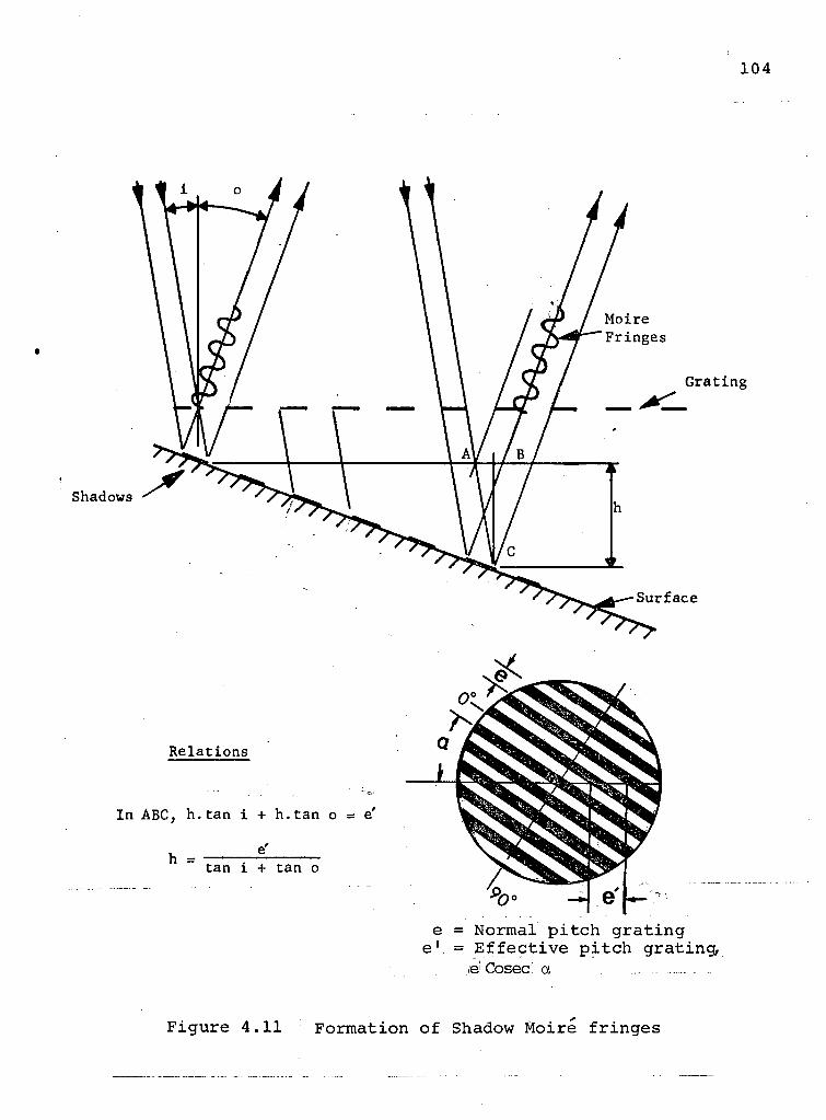
104
& Cosec a
Figure 4.11 Formation of Shadow Moire fringes

105
In the r e l a t i o n f o r contour i n t e r v a l ' h ' (F igure
4.11), a p r o v i s i o n f o r a l t e r i n g the s e n s i t i v i t y can be s e e n .
Hence, i n s t e a d o f o b s e r v i n g the f r i n g e s n o r m a l l y , they were
photographed at an angle 0 = 45°. The g r a t i n g used had a
p i t c h o f 200 l i n e s per i n c h and was a r ranged a t i t s normal
p i t c h g r a t i n g .
The models o f s o l i d d i s c and arched m i r r o r s u b s t r a t e s
were p r e p a r e d by p o u r i n g a mix ture o f l i q u i d s i l i c o n e rubber
and a c a t a l y s t i n c a r e f u l l y p r e p a r e d moulds , as suggested
i n the Dow C o r n i n g b u l l e t i n 08-417 [57].
The Young's modulus o f s i l i c o n e rubber was determined
by a p p l y i n g a f i n i t e compress ion on a c y l i n d e r o f s i l i c o n e
rubber [58]. I t was found t o be 160 p s i .
The h i g h l y f l e x i b l e c h a r a c t e r o f the s i l i c o n e rubber
m a t e r i a l p r e s e n t e d some d i f f i c u l t y i n r e a l i z i n g p roper
boundary c o n d i t i o n s . However, by u s i n g the s u p p o r t i n g
t e c h n i q u e as i n d i c a t e d i n F i g u r e 4.12, i t was p o s s i b l e t o
approximate the boundary c o n d i t i o n s used i n the a n a l y s i s
( s e c t i o n 3.3.1) .
In o r d e r t o o b t a i n a p r e c i s e l y f l a t s u r f a c e o f the
mode l , a mould was c a r e f u l l y c o n s t r u c t e d w i t h the accuracy
o f 0.001 i n c h . However, the c u r i n g p rocess r e s u l t e d i n
some s h r i n k a g e o f the model thus l e a d i n g t o an i n i t i a l
c u r v a t u r e o f the s u r f a c e .
In o r d e r t o e l i m i n a t e the u n c e r t a i n t y c o n c e r n i n g
the e x t e n t o f the i n i t i a l c u r v a t u r e p r e s e n t , the d e f l e c t i o n s
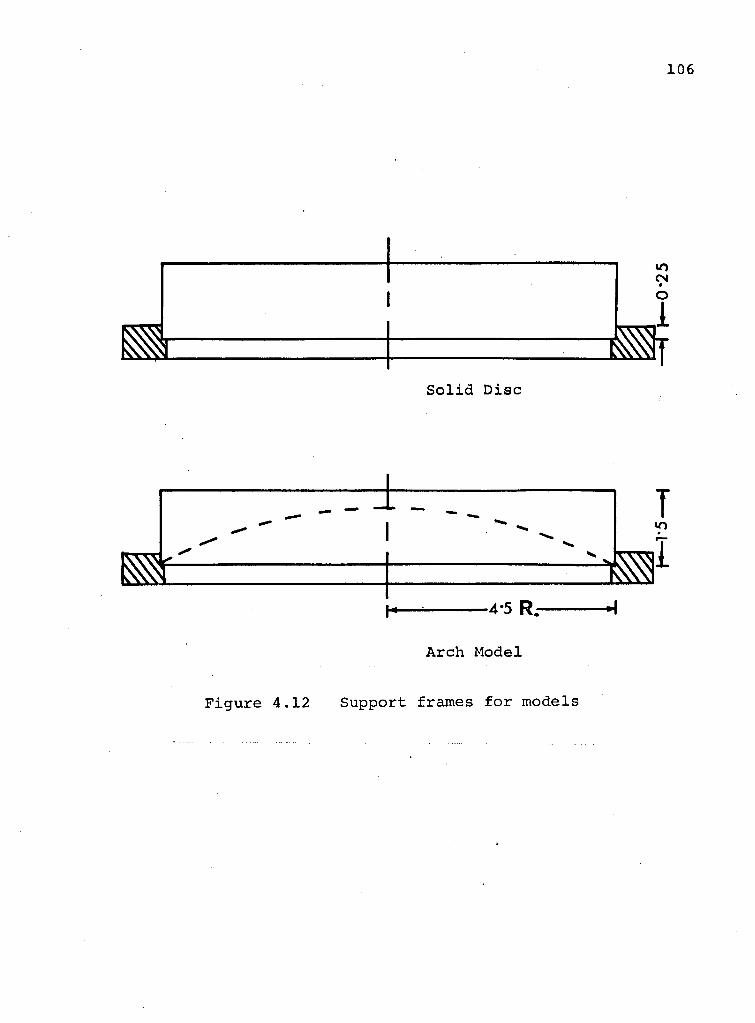
Arch Model
Figure 4.12 Support frames for models
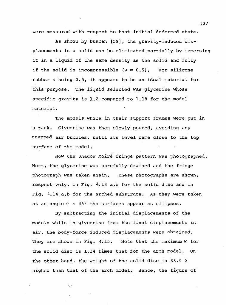
107 were measured w i t h r e s p e c t t o t h a t i n i t i a l deformed s t a t e .
As shown by Duncan [59] , the g r a v i t y - i n d u c e d d i s
p lacements i n a s o l i d can be e l i m i n a t e d p a r t i a l l y by immersing
i t i n a l i q u i d o f the same d e n s i t y as the s o l i d and f u l l y
i f the s o l i d i s i n c o m p r e s s i b l e (v = 0.5). Fo r s i l i c o n e
rubber v b e i n g 0.5, i t appears t o be an i d e a l m a t e r i a l f o r
t h i s p u r p o s e . The l i q u i d s e l e c t e d was g l y c e r i n e whose
s p e c i f i c g r a v i t y i s 1.2 compared t o 1.18 f o r the model
m a t e r i a l .
The models w h i l e i n t h e i r s u p p o r t frames were put i n
a t ank . G l y c e r i n e was then s l o w l y p o u r e d , a v o i d i n g any
t r a p p e d a i r b u b b l e s , u n t i l i t s l e v e l came c l o s e to the top
s u r f a c e o f the model .
Now the Shadow Moi re f r i n g e p a t t e r n was photographed .
N e x t , the g l y c e r i n e was c a r e f u l l y d r a i n e d and the f r i n g e
photograph was taken a g a i n . These photographs are shown,
r e s p e c t i v e l y , i n F i g . 4.13 a ,b f o r the s o l i d d i s c and i n
F i g . 4.14 a ,b f o r the a rched s u b s t r a t e . As they were taken
at an ang le 0 = 4 5 ° the s u r f a c e s appear as e l l i p s e s .
By s u b t r a c t i n g the i n i t i a l d i s p l a c e m e n t s o f the
models w h i l e i n g l y c e r i n e f rom the f i n a l d i s p l a c e m e n t s i n
a i r , the b o d y - f o r c e induced d i s p l a c e m e n t s were o b t a i n e d .
They are shown i n F i g . 4.15. Note t h a t the maximum w f o r
the s o l i d d i s c i s 1.34 t imes t h a t f o r the a r c h model , On
the o t h e r hand, the we ight o f the s o l i d d i s c i s 35.9 %
h i g h e r than t h a t o f the a r c h mode l . Hence, the f i g u r e o f
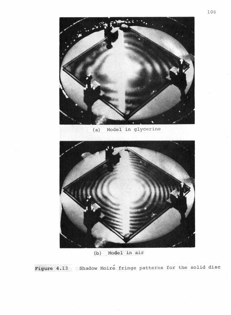
1 0 8
109

110
Figure 4.15 Comparison of gravity-induced upper deflections for the s o l i d d i s c with the arch model
surface w that of
I l l
merit, based on the maximum d e f l e c t i o n , i s 2.09, thus
c l e a r l y showing the supe r i o r i t y of the arched substrate.
4.3 A p p l i c a b i l i t y of the Model Results to the Prototype Mirror Substrate Design
In applying model r e s u l t s to the prototype, i t i s
important to account for the d i f f e r i n g values of Poisson's
r a t i o . S i l i c o n e rubber has v = 0.5, whereas the prototype
mirror substrate materials have much lower values of v .
Some of the l i k e l y materials for mirror substrate, such as
fused s i l i c a and beryllium, have Poisson's r a t i o of 0.17
and 0.025, respectively. This thus raises a question re
garding the a p p l i c a b i l i t y of the model te s t r e s u l t s .
Clutterbuck [60] from experimental and a n a l y t i c a l
studies found the peak stresses for v = 0.5 to be 10% higher
than those for v = 0.3. This was substantiated by Kenny's
[61] analysis which showed experimental investigations with
models of v = 0.5, to predict peak stresses 15% higher for
the beryllium prototype.
In the present case the e f f e c t of v on stress
d i s t r i b u t i o n and displacement i s evaluated using the
a n a l y t i c a l expressions (2.17) and (2.21). The d i s t r i b u t i o n
of r a d i a l stress a r i s shown i n F i g . 4.16. This analysis
shows that with increasing value of v , the peak stresses
also increase whereas the maximum displacement decreases.
Furthermore> i t shows that the maximum displacement predicted
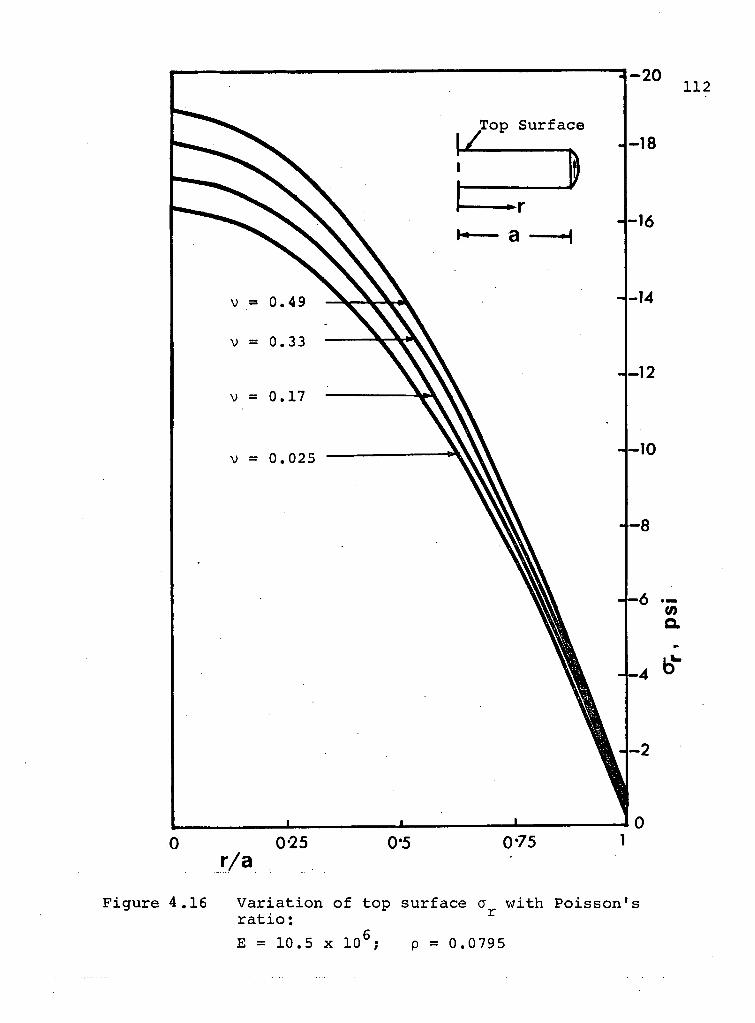
by m o d e l s o f v = 0.49 w o u l d be 28.8% l o w e r f o r t h e f u s e d
s i l i c a ( v = 0.17) p r o t o t y p e . F o r t u n a t e l y , t h i s d o e s n o t
a f f e c t t h e c o n c l u s i o n c o n c e r n i n g t h e f i g u r e o f m e r i t b a s e d
on g e o m e t r y .
5. CONCLUSIONS AND RECOMMENDATIONS FOR FUTURE STUDY
5.1 C o n c l u s i o n s
Important f e a t u r e s o f the i n v e s t i g a t i o n and c o n c l u
s i o n s based on i t may be summarized as f o l l o w s :
i ) The s e l f - w e i g h t prob lem of the t r a d i t i o n a l c i r c u l a r
d i s c m i r r o r s u b s t r a t e has been i n v e s t i g a t e d and an
a n a l y t i c a l s o l u t i o n , not p r e v i o u s l y noted i n
the l i t e r a t u r e , has been o b t a i n e d .
i i ) The f i n i t e e lement s o l u t i o n , i n terms o f t r i a n g u l a r
r i n g - e l e m e n t s , c l e a r l y demonstrates the s u p e r i o r i t y
o f a r c h - t y p e s t r u c t u r e s over s o l i d d i s c s . T h i s
would make a r c h d e s i g n s p a r t i c u l a r l y s u i t e d i n
the c o n s t r u c t i o n o f an o r b i t i n g t e l e s c o p e where
weight would be one o f the major c o n s i d e r a t i o n s ,
i i i ) The m o d i f i e d f i n i t e e lement programme, capab le
o f a n a l y z i n g d e f o r m a t i o n s due to t h e r m a l e f f e c t s ,
shows t h a t the presence o f a s m a l l temperature
g r a d i e n t can produce a p p r e c i a b l e d e f o r m a t i o n s i n
the m i r r o r s u b s t r a t e .
i v ) The f r o z e n s t r e s s p h o t o e l a s t i c i t y exper iment c l e a r l y
i n d i c a t e s i t s l i m i t a t i o n s i n e v a l u a t i n g the body f o r c e
115
induced d i s p l a c e m e n t s . T h i s i s p r i m a r i l y due t o
the d i f f i c u l t y i n o b t a i n i n g a s u f f i c i e n t l y s t r e s s
f r e e model m a t e r i a l . F r i n g e m u l t i p l i c a t i o n up t o
17X was s u c c e s s f u l l y o b t a i n e d d u r i n g the p r e s e n t
e x p e r i m e n t s .
v) The f r o z e n d i s p l a c e m e n t s t u d i e s p r o v i d e u s e f u l
i n s i g h t i n t o the l i m i t a t i o n s o f epoxy models i n
measur ing body f o r c e induced d i s p l a c e m e n t s . T h i s
i s due to the phenomenon o f con t inuous p o l y m e r i
z a t i o n o f epoxy r e s i n s ,
v i ) The i n v e s t i g a t i o n on c o l d cure s i l i c o n e
models c l e a r l y e s t a b l i s h e s t h e i r
u s e f u l n e s s i n s t u d y i n g s e l f - w e i g h t d e f o r m a t i o n s .
These exper iments show the s u p e r i o r i t y o f an arched
d e s i g n compared t o the d i s c c o n f i g u r a t i o n ,
v i i ) A d i f f e r e n c e i n the P o i s s o n ' s r a t i o would n a t u r a l l y
l e a d to a d i s c r e p a n c y between the model and p r o t o
type s t r e s s d i s t r i b u t i o n s . However, i t i s impor tan t
to r e c o g n i z e t h a t t h i s i n no way p r e c l u d e s the
use o f models i n e s t a b l i s h i n g the s u p e r i o r i t y o f
a p a r t i c u l a r geomet r i c c o n f i g u r a t i o n .
5.2 Recommendations f o r F u t u r e Study
The i n v e s t i g a t i o n p r e s e n t e d here aims at demons t ra t ing
the f a v o u r a b l e i n f l u e n c e o f the a r c h as a p p l i e d t o a m i r r o r
s u b s t r a t e d e s i g n . A s e a r c h f o r the optimum a r c h r e p r e s e n t s
116
a l o g i c a l e x t e n s i o n t o the s t u d y .
Fo r a t h r e e - p o i n t suppor t sys tem, the model can be
f u r t h e r m o d i f i e d by removing m a t e r i a l i n the form o f an
a r c h i n the t a n g e n t i a l d i r e c t i o n between suppor t p o i n t s
( F i g . 5 . 1 ) . T h i s would encourage t a n g e n t i a l t r a n s m i s s i o n
o f body f o r c e s t o r e a c t i v e p o i n t s th rough a r c h i n g r a t h e r
than f l e x u r e .
The s i g n i f i c a n c e o f a rched s u b s t r a t e , thus e s t a b l i s h e d ,
l e a d s t o numerous v a r i a t i o n s i n d e s i g n s . Fo r example , a
d e s i g n shown i n F i g . 5.2 appears to be p a r t i c u l a r l y p r o m i s i n g
and needs to be e x p l o r e d f u r t h e r . Here each l i t t l e b l o c k
o f m a t e r i a l i s suppor ted by the a r c h be low. The r a d i a l and
c i r c u m f e r e n t i a l c u t s r e l e a s e t r a n s m i s s i o n o f bend ing i n the
r e s p e c t i v e d i r e c t i o n s . There i s a p o s s i b i l i t y o f d e g r a d a t i o n
o f image due to d i f f r a c t i o n around the edges o f the b l o c k s .
However, a m i r r o r i n the form o f a p l a t e p l a c e d at the top
o f the a rched s u b s t r a t e may c o r r e c t t h i s (do t ted l i n e s i n
F i g . 5 . 2 ) .
The arched forms o f s u b s t r a t e s may p r e s e n t some
d i f f i c u l t y w h i l e p o l i s h i n g the r e f l e c t i v e s u r f a c e o f the
m i r r o r . There i s a l s o a p o s s i b i l i t y o f g e n e r a l ' q u i l t i n g '
o f the a p e r t u r e due t o t h e r m a l s t r a i n i n g o f s u b s t r a t e s
w i t h v a r i a b l e t h i c k n e s s . These problems need d e t a i l e d
i n v e s t i g a t i o n s .
The p r e s e n t e x p e r i m e n t a l i n v e s t i g a t i o n s show the
l i m i t a t i o n s o f the p h o t o e l a s t i c approach f o r the e v a l u a t i o n

117
Figure 5.1 Arched substrate form for three-point supports
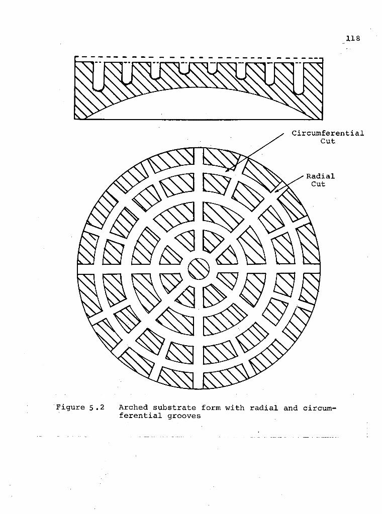
118
Figure 5.2 Arched substrate form with r a d i a l and circumf e r e n t i a l grooves
119
o f s e l f - w e i g h t d e f l e c t i o n s . Techn iques t o produce c a s t i n g s
w i t h n e g l i g i b l e m o t t l e may be e x p l o r e d . F r o z e n d i s p l a c e m e n t
measurements s h o u l d be conducted i n an i n e r t atmosphere to
e l i m i n a t e r e a c t i o n o f the polymer groups w i t h the a tmospher i c
oxygen .
For a g e n e r a l t h r e e - d i m e n s i o n a l s u b s t r a t e system a
f i n i t e e lement t e c h n i q u e may prove t o be i d e a l . But computer
s t o r a g e and l a r g e i n p u t d a t a p r e p a r a t i o n may p r e s e n t some
d i f f i c u l t i e s . However, the use o f i s o p a r a m e t r i c f i n i t e
e lements would h e l p s t r e a m l i n e the p r o c e d u r e . In any case
t h i s g e n e r a l prob lem needs f u r t h e r a t t e n t i o n .

REFERENCES
1. R i t c h e y , G.W. "On Modern R e f l e c t i n g T e l e s c o p e s , " Smi thson ian C o n t r i b u t i o n s to Knowledge, V o l . 34, 1904, pp . l O 1 1 ! ^
2. B a u s t i a n , W.W., "Genera l P h i l o s o p h y o f M i r r o r Support Sys tems ," P r o c e d i n g s o f the O p t i c a l T e l e s c o p e Technology Workshop, M a r s h a l l Space F l i g h t C e n t e r , NASA, 1970, pp . 381-387.
3. Couder , A . , B u l l . A s t r o n . , V o l . 7, 1931, p. 14.
4. Schwes inger , G . , " O p t i c a l E f f e c t o f F l e x u r e i n V e r t i c a l l y Mounted P r e c i s i o n M i r r o r s , " J . Op t . Soc . o f A m e r i c a , V o l . 44, 1954, p p . 417-424.
5. M a l v i c k , A . J . , and P e a r s o n , E . T . , " T h e o r e t i c a l E l a s t i c De fo rmat ion o f 4-M D iameter O p t i c a l M i r r o r U s i n g Dynamic R e l a x a t i o n , " A p p l i e d O p t i c s , V o l . 7, No. 6, June 1968, pp . 1207-1212.
6. Kenny, B . , "The D e f l e c t i o n o f O p t i c a l S t r u c t u r e s , " ER-9538, 1968, P e r k i n - E l m e r , C o n n e c t i c u t , U . S . A .
7. L o v e , A . E .H . , A T r e a t i s e on the M a t h e m a t i c a l Theory o f E l a s t i c i t y , 4th e d . , Dover P u b l i c a t i o n s , New Y o r k , T9"44, pp . 455-487, 108-109 .
8. W i l l i a m s , R., " D e f l e c t i o n S u r f a c e o f a C i r c u l a r P l a t e w i t h M u l t i p o i n t S u p p o r t , " 9136, 1968, P e r k i n - E l m e r , C o n n e c t i c u t , U . S . A .
9 . B a s s a l i , W.A . , "T ransverse F l e x u r e o f T h i n E l a s t i c P l a t e s Supported a t S e v e r a l P o i n t s , " P r o c . Cambridge P h i l . S o c , V o l . 53, 1957, p. 728.
10. Vaughan, H . , " D e f l e c t i o n o f U n i f o r m l y Loaded C i r c u l a r P l a t e s Upon E q u i s p a c e d P o i n t S u p p o r t s , " J . of_ S t r a i n A n a l y s i s , V o l . 5, No. 2, 1970, pp . 115-120.
11 . M i c h e l l , J . H . , "The F l e x u r e o f C i r c u l a r P l a t e s , " P r o c . London Math . S o c . , V o l . 34, 1902, p. 223.
12. Duncan, J . P . , " F l e x u r a l R i g i d i t y o f M u l t i p l y Connected P l a t e s , " V o l . 4, 19 58, U n p u b l i s h e d Memoir.
121
13. T imoshenko, S . , and G o o d i e r , J . N . , Theory o f E l a s t i c i t y , 2nd e d . , M c G r a w - H i l l , New York , 1951, pp . 3T9-352, 421-423.
14. A l l e n , D .N. d e G . , C h i t t y , L . , P i p p a r d , A . J . S . and Savern , R . T . S . , "The E x p e r i m e n t a l and M a t h e m a t i c a l A n a l y s i s o f A r c h Dams w i t h S p e c i a l Re fe rence to b o k a n , " P r o c . I n s t . C i v i l E n g i n e e r s , V o l . 5, P t . 1, 1956, pp . 198-258.
15. Emerson, E . B . , " D e t e r m i n a t i o n o f P laneness and Bending o f O p t i c a l F l a t s , " J n l . Res . Na t . B u r . S t a n d a r d s , V o l . 49 , No. 4, Oc tober 1952, pp . 241-24 7.
16 . S o u t h w e l l , R . V . , "Some P r a c t i c a l l y Important S t r e s s Systems i n S o l i d s o f R e v o l u t i o n , " P r o c . Roya l Soc . V o l . 180-A, J u l y 1942, pp . 367-396.
17. A l l e n , D.N. d e G . , and W i n d l e , D.W., "The F i n i t e D i f f e r e n c e A p p r o a c h , " S t r e s s A n a l y s i s , e d i t e d by Z i e n k i e w i c z , O . C . , and H o l i s t e r , G . S . , John W i l e y and Sons, London, 19 65, pp . 3-19.
18. Day, A . S . , "An I n t r o d u c t i o n to Dynamic R e l a x a t i o n , " The E n g i n e e r , V o l . 219, January 1965, pp . 218-221.
19 . O t t e r , J . R . H . , C a s s e l , A . C . C . , and Hobbs, R . E . , "Dynamic R e l a x a t i o n , " P r o c . I n s t . C i v i l E n g i n e e r s , V o l . 35, 1966, pp . 633-656.
20. A p p l , F . J . , and K o e r n e r , D .R . , "Numer ica l A n a l y s i s o f P lane E l a s t i c i t y P r o b l e m s , " P r o c . ASCE, J . Eng . Mech. D i v . , June 1968, pp . 743-751.
21. Massonnet , C . E . , "Numer ica l Use o f I n t e g r a l P r o c e d u r e s , " S t r e s s A n a l y s i s , e d i t e d by Z i e n k i e w i c z , O . C . , and H o l i s t e r , G . S . , John Wi ley and Sons, London, 1965, pp . 198-235.
22. T u r n e r , M . J . , C l o u g h , R.W., M a r t i n , H . C . , and Topp, L . J . , " S t i f f n e s s and D e f l e c t i o n A n a l y s i s o f Complex S t r u c t u r e s , " J . A e r o . S c i . , V o l . 23, 19 56, pp . 805-23.
23. H r e n n i k o f f , A . , " S o l u t i o n o f Problems i n E l a s t i c i t y by the Framework Method ," J . A p p l . M e c h . , V o l . 8, 1941, pp . A169-A175.
24. McHenry, D . , "A L a t t i c e Ana logy f o r the S o l u t i o n o f P lane S t r e s s P r o b l e m s , " J . I n s t . C i v i l E n g r s . , V o l . 21, No. 2, 1941, pp . 59-82
122
25. C l o u g h , R.W., "The F i n i t e E lement Method i n S t r u c t u r a l M e c h a n i c s , " S t r e s s A n a l y s i s , e d i t e d by Z i e n k i e w i c z , O . C . , -and H o l i s t e r , G . S . , John Wi ley and Sons , London, 1965, pp . 85-119.
26. Z i e n k i e w i c z , O . C . , and Cheung, Y . K . , The F i n i t e E lement Method i n S t r u c t u r a l and Continuum M e c h a n i c s , R e v i s e d 1 s t i m p r e s s i o n , M c G r a w - H i l l , London, 1968, p p . 46 -61 , 15-16 .
27. C l o u g h , R.W., and R a s h i d , Y . , " F i n i t e E lement A n a l y s i s o f Ax i symmet r i c S o l i d s , " P r o c . ASCE, Eng . Mech. D i v . , V o l . 91, 1965, pp . 71-85 .
28. Simmons, (5.A., "The Des ign o f L i g h t w e i g h t C e r - V i t M i r r o r B l a n k s , " P r o c e d i n g s o f the O p t i c a l T e l e s c o p e Techno logy Workshop, M a r s h a l l Space F l x g h t C e n t e r , NASA, 1970, pp . 219-239.
29. A u g u s t y n , W., " L i g h t Weight O p t i c a l E l e m e n t s - S t a t e o f the A r t 1960," 5688, 1960, P e r k i n - E l m e r , C o n n e c t i c u t , U . S . A .
30. B a r n e t t , R . L . , "Survey o f Optimum S t r u c t u r a l D e s i g n , " P r o c . SESA, V o l . 24, December 1966, pp . 19A-26A.
31. Duncan, J . P . , " S e l f - W e i g h t Loaded S t r u c t u r e s i n the Context o f L i g h t w e i g h t M i r r o r A p p l i c a t i o n s , " P r o ced ings o f the O p t i c a l T e l e s c o p e Techno logy Workshop, M a r s h a l l Space F l i g h t C e n t e r , NASA, 1970, pp . 257-280.
32. Johnson,• E .W. , "Optimum M i c h e l l F rames , " Ph .D . T h e s i s , The U n i v e r s i t y o f B r i t i s h Co lumb ia , September 1970.
33. Kenny, B . , "A Compar ison o f the S e l f - W e i g h t D e f l e c t i o n s o f S p h e r i c a l S h e l l s and T h i c k C i r c u l a r P l a t e s o f Cons tant T h i c k n e s s , " 9353, 1967, P e r k i n - E l m e r , C o n n e c t i c u t , U . S . A .
34. Ho land , I. , and B e l l , K. , F i n i t e E lement Methods i n S t r e s s A n a l y s i s , T a p i r , Norway, 1969, pp . 1 0 - 1 1 .
35. P u l f r i c h , C , Z. I n s t r . , V o l . 18, 1898, p. 261.
36. G a t e s , J . W . , "The E v a l u a t i o n o f I n t e r f e r o g r a m s by D i sp lacement and S t e r e o s c o p i c Methods , 1 1 B r i t . J . A p p l . P h y s . , V o l . 5, A p r i l 1954, p p . ' 1 3 3 - 1 3 5 .
37. Dew, G . D . , "The Measurement o f O p t i c a l F l a t n e s s , " J . S c i . I n s t r u m . , V o l . 43, J u l y 1966, p p . 409-415.
38. Dew, G . D . , "Systems o f Minimum D e f l e c t i o n Supports f o r O p t i c a l F l a t s , " J . S c i . Ins t rum. V o l . 43, November 1966, pp . 809-811.
123
39. Unwin, W.B., "Simulation of Gravity Induced Deformation by Immersion/* 1968, Mech. Eng. Dept., The University of B r i t i s h Columbia, Vancouver, Canada.
40. Frocht, M.M., Ph o t o e l a s t i c i t y , Vols. I and I I , John Wiley and Sons, New York, 1966.
41. Dally, W.J., and Riley, W.F., Experimental Stress Analysis, McGraw-Hill, New York, 1965.
42. Hetenyi, M., Handbook of Experimental Stress Analysis, John Wiley and" Sons, New York, 1950, p. 76 8.
43. Biot, M.A., "Distributed Gravity and Temperature Loading i n Two-Dimensional E l a s t i c i t y Replaced by Boundary Pressures and Dislocations," Trans. ASME, J. Appl. Mech., Vol. 57, 1935, pp. A41-A45.
44. Serafim, J.L.,and Da Costa, J.P., "Methods and Materials for the Study of the Weight Stresses i n Dams by Means of Models," International Colloquium o f Models of Structures, June 19 59, Madrid, pp. 4~9-56.
45. Parks, V.J., D u r e l l i , A.J.,and Ferrer, L,, "Gravit a t i o n a l Stresses Determined Using Immersion Techniques," Trans. ASME, J . Appl. Mech., September 1967, pp. 583-590.
46. Post, D., "Isochromatic Fringe Sharpening and M u l t i p l i c a t i o n i n Ph o t o e l a s t i c i t y , " Proc. SESA, Vol. 12, No. 2, 1955, pp. 143-156.
47. Post, D., "Fringe M u l t i p l i c a t i o n i n Three-Dimensional Ph o t o e l a s t i c i t y , " J. Strain Analysis, Vol. 1, No. 5, 1965, pp. 380-388.
48. Cook, R.D., "On the Type of Photoelastic Mottle i n an Epoxy Resin," Proc. SESA, Vol. 21, No. 1, May 1954, pp. 151-152.
49. Post, D., "Photoelastic-fringe M u l t i p l i c a t i o n - F o r Tenfold Increase i n S e n s i t i v i t y , " Experimental Mechanics, Vol. 10, No. 8, August 1970 , pp. 3~0~5-312.
50. Leven, M.M., "Epoxy Resins for Photoelastic Use," Pho t o e l a s t i c i t y , edited by Frocht, M.M., Pergamon Press, New York, 1963, pp. 145-165.
51. Kenny, B., "Stress Distributions i n Thick Axisymmetric Engineering Components," Ph.D. Thesis, S h e f f i e l d University, 1966

124
52. Duncan, J.P., "Topographical Survey of Curved Aerodynamic Surfaces," 1970, F i n a l Report to D.R.B., Mech..Eng. Dept., The University of B r i t i s h Columbia, Vancouver, Canada.
53. Bajaj, V.K.,"Design and Development of an Oblique Incidence Interferometer," M.A. Sc. Thesis, The University of B r i t i s h Columbia, 1971.
54. Weller, R., and Shephard, B.M., "Displacement Measurements by Mechanical Interferometry," Proc. SESA, Vol. 6, No. 1, 1948, pp. 35-38.
55. Theocaris, P.S., Moire Fringes i n Strain Analysis, Pergamon Press, New York", 1969.
56. Duncan, J.P., Crofton, J.P., Sikka, S., and Talapatra, D., "A Technique for the Topographical Survey of B i o l o g i c a l Surfaces," Med, and B i o l . Engng., Vol. 8, 1970, pp. 425-426. "
57. Dow Corning B u l l e t i n : 08-417, 1969, Dow Corning Silico n e s Inter-America Ltd.
58. Vaughan, H., "The F i n i t e Compression of E l a s t i c S o l i d Cylinders i n the Presence of Gravity," Proc. Roy. Soc. Lond., Vol. A321, 1971, pp. 381-396.
59. Duncan, J.P., "The Elimination of Gravity-Induced Displacements i n An E l a s t i c S o l i d by Immersion i n An Ideal F l u i d , " Unpublished typescript, 1967, Mech. Eng. Dept., The University of B r i t i s h Columbia, Vancouver, Canada.
60. Clutterbuck, M., "The Dependence of Stress D i s t r i b u tions on E l a s t i c Constants," B r i . J n l . of Appl. Physics, Vol. 9, August 1958, pp. 323-329.
61. Kenny, B., "The E f f e c t of Poisson's Ratio on Stress D i s t r i b u t i o n s , " The Engineer, Vol. 218, October 1964, pp. 706-712T"
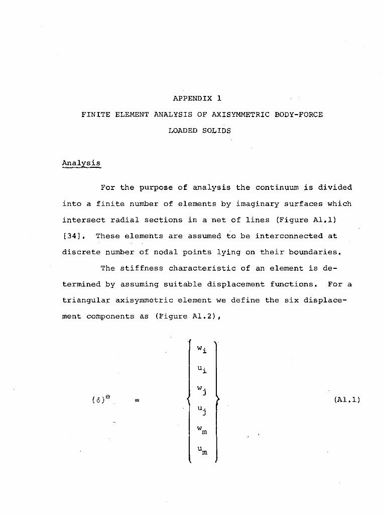
APPENDIX 1
FINITE ELEMENT ANALYSIS OF AXISYMMETRIC BODY-FORCE
LOADED SOLIDS
A n a l y s i s
For the purpose o f a n a l y s i s the cont inuum i s d i v i d e d
i n t o a f i n i t e number o f e lements by imag inary s u r f a c e s which
i n t e r s e c t r a d i a l s e c t i o n s i n a ne t o f l i n e s (F igure A l . l )
[ 3 4 ] . These e lements are assumed to be i n t e r c o n n e c t e d a t
d i s c r e t e number o f n o d a l p o i n t s l y i n g on t h e i r b o u n d a r i e s .
The s t i f f n e s s c h a r a c t e r i s t i c o f an e lement i s d e
te rmined by assuming s u i t a b l e d i s p l a c e m e n t f u n c t i o n s . F o r a
t r i a n g u l a r ax i symmetr i c e lement we d e f i n e the s i x d i s p l a c e
ment components as (F igure A 1 . 2 ) ,
{<5}E
Wj
w
u. 3
w m
u m
( A l . l )

Figure A l . l
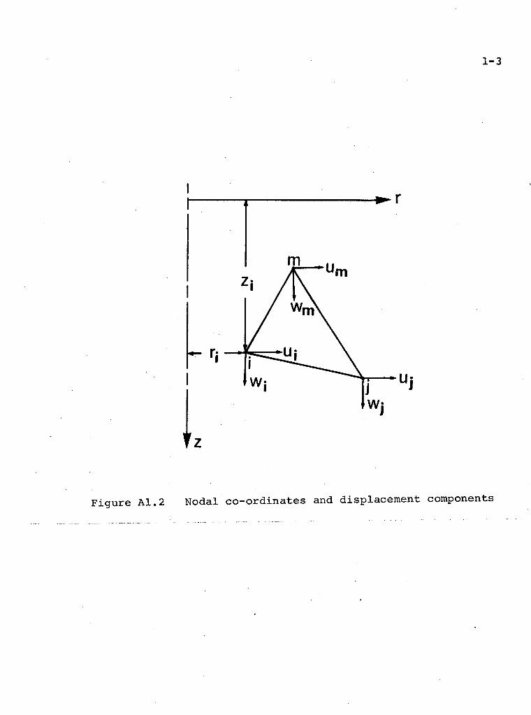
1-3
F i g u r e A1.2 Nodal c o - o r d i n a t e s and d i s p l a c e m e n t components

The functions should be so selected as to s a t i s f y the
compatibility conditions. This i s achieved by assuming
displacements that vary l i n e a r l y i n each d i r e c t i o n . The
edges of the elements would then displace as s t r a i g h t l i n e s ,
and no gaps can develop between them so long as nodal
continuity i s maintained [ 3 3 ] .
Let the displacement functions be represented by
l i n e a r polynominals as,
{A}
a 1
a 2
{T} a 3 V (A1.2)
a 4
a 5
a 6
The constants a's are determined by i n s e r t i n g the nodal co
ordinates of the element (Figure A 1 . 2 ) ,
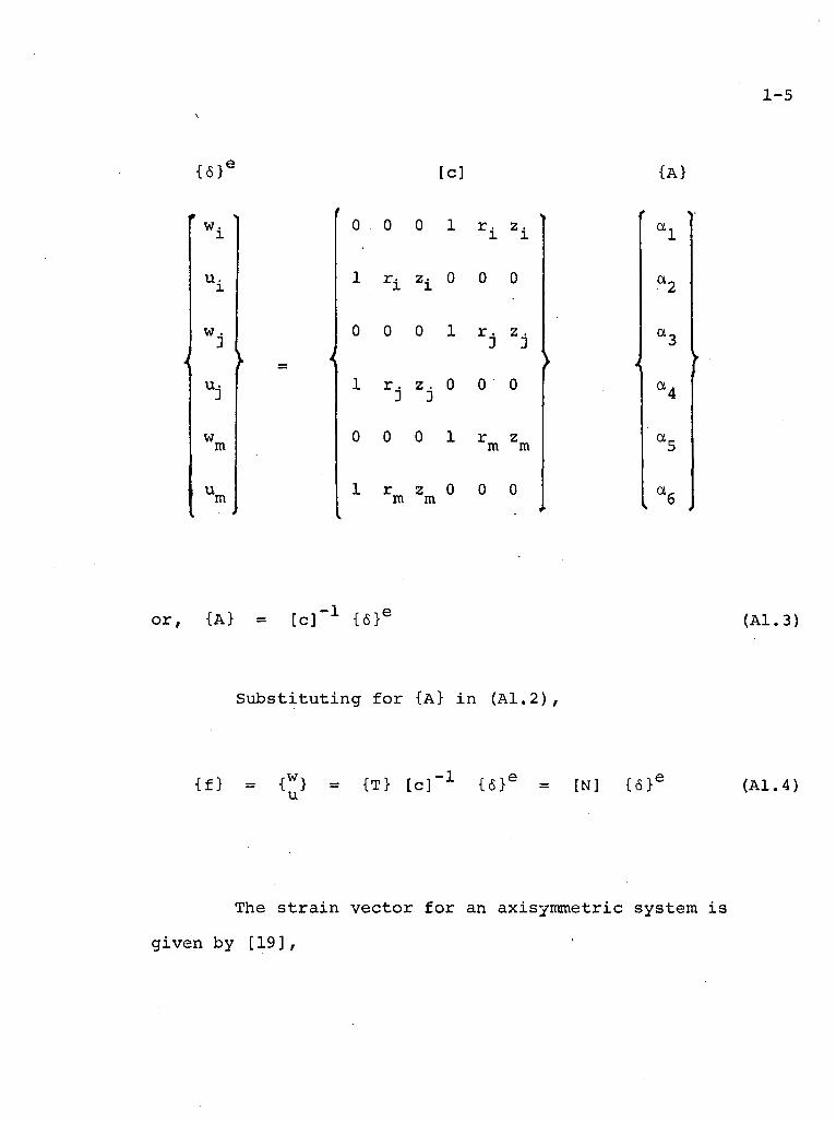
1-5
{6}' tc] {A}
w. 1
u.
w . 3
w m
u m
0 . 0 0 1 r i z i
1 r± z i 0 0 0
0 0 0 1 r. z. 3 D
1 r. z . 0 0 0
0 0 0 1 r z m m
1 r z 0 0 0 m m
a.
a.
a.
a .
a .
or, {A} = [ c ] " 1 {6} e (A1.3)
Substituting for {A} i n (A1.2)
{f} = {*} = {T} [ c ] " 1 {6} e = [N] {<5}e (A1.4)
The s t r a i n vector for an axisymmetric system i s
given by [19],
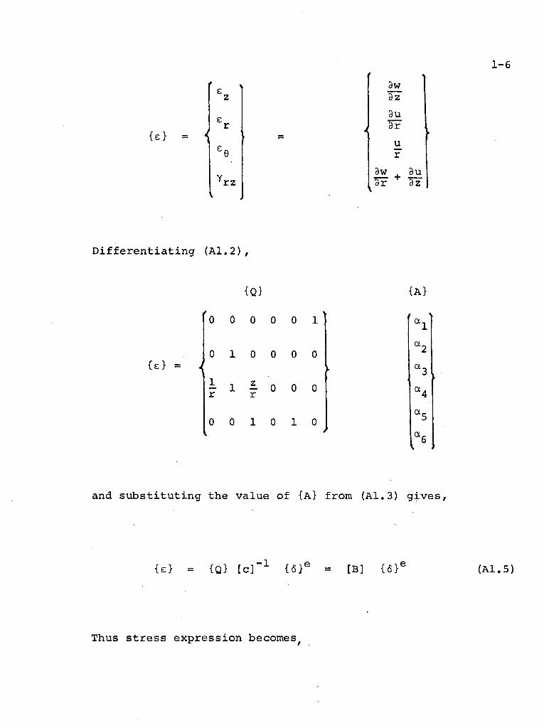
1-6
r z
3w Sz
9u dr
u r
9w , 3u Sr + Tz
D i f f e r e n t i a t i n g ( A 1 . 2 ) ,
{Q}
0 0 0 0 0 1
0 1 0 0 0 0
- 1 - 0 0 0 r r
0 0 1 0 1 0
{A}
a.
a.
a.
a.
ex.
and s u b s t i t u t i n g the va lue o f {A} from ( A l . 3 ) g i v e s ,
{£} = {Q> [ c ] " X { 6 } e = [B] {6Y (A1.5)
Thus s t r e s s e x p r e s s i o n becomes^

1-7
{a} [D] { e } (A1.6)
r z
w h e r e [D] i s t h e e l a s t i c i t y m a t r i x w h i c h f o r i s o t r o p i c m a t e r
i a l s i s g i v e n b y ,
[D] = E ( l - v )
(1+v ) ( l-2v)
1-v
v - v
v 1 -v
1
V
1 -v
0
V 1 -v
V 1 -v
1-2V 2(1 - v )
C o n s i d e r now t h e n o d a l f o r c e s
{F}
m./
w h i c h a r e e q u i v a l e n t t o t h e b o u n d a r y s t r e s s e s a n d d i s t r i b u t e d
l o a d s d u e t o b o d y f o r c e s {p} a s s o c i a t e d w i t h t h e e l e m e n t .
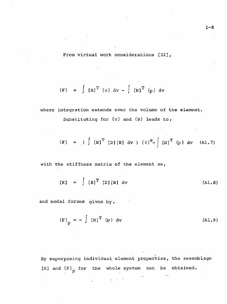
1-8
From v i r t u a l work considerations [32],
{F} = { [ B ] T {0} dv - I [N] T {p} dv
where integration extends over the volume of the element.
Substituting for {a} and {B} leads t o ,
{F} = ( { [ B ] T [D][B] dv ) { 6 } E -e [N] T {p} dv (A1.7)
with the s t i f f n e s s matrix of the element as,
[K] = / [ B ] T [D][B] dv (A1.8)
and nodal forces given by , ,
{F} = - J [N] T {p} dv (A1.9) P J
By superposing i n d i v i d u a l element properties, the assemblage
[K] and {F} . for the whole system can be obtained. P
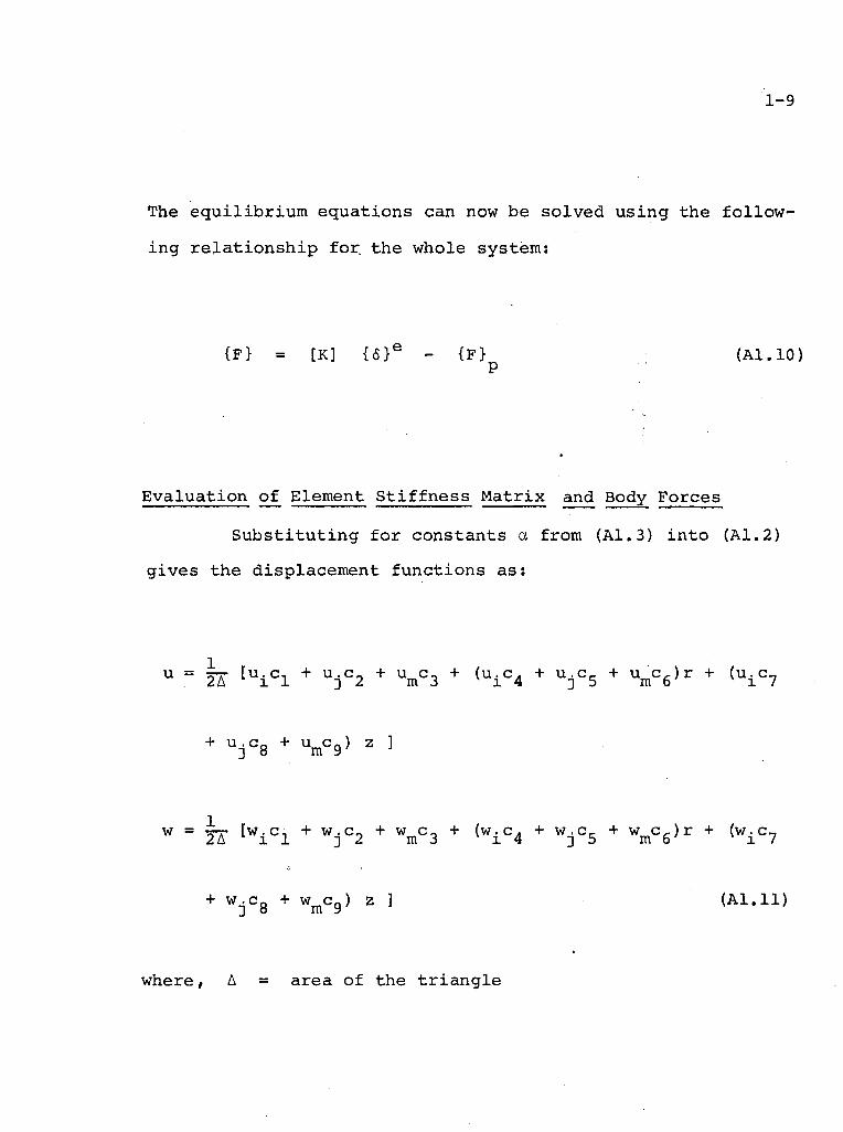
1-9
The e q u i l i b r i u m e q u a t i o n s can now be s o l v e d u s i n g the f o l l o w
i n g r e l a t i o n s h i p f o r the whole sys tem:
{F> = [K] { 6 } e - {F} ( A L I O ) P
E v a l u a t i o n o f Element S t i f f n e s s M a t r i x and Body F o r c e s
S u b s t i t u t i n g f o r c o n s t a n t s a from (A1.3) i n t o (A l . 2 )
g i v e s the d i s p l a c e m e n t f u n c t i o n s a s :
u ° JK t u i c l + U j C 2 + u m c 3 + ( u i C 4 + u j c 5 + u m C 6 ) r + ( u i c 7
+ u j c 8 + W 2 ]
W = TK I w i C l + W j C 2 + w m C 3 + ( w i C 4 + w j C 5 + W m c 6 ) r + ( w i C 7
+ W j C g + W ^ g ) 2 ] ( A l . l l )
where, A = area of the t r i a n g l e

c, = r . z_ - z . r , c n = z . r - r . z , c~ = r . z 1 3m 3m' 2 l m i m ' 3 1
c . = z . - z , 4 3 m ' c , = z - z . . 5 m i ' c , = z . 6 1
c . = r - r . , 7 m 3 ' c Q = r. - r .
8 1 m ' C 9 = r j
The s t r a i n components are now r e a d i l y o b t a i n e d a s :
t \ e
z
Y r z
1_ 2A
c ? 0 c 8 0 c 9 0
0 c„ 0 c_ 0 c , 4 D 6
0 c 1 Q 0 c x l 0 c 1 2
C 4 C 7 C5 °8 C6 °9
w. 1
u. 1
w . 3
u.
w^ m
u m
where,
C 1 0 = C l / r + c 4 + c 7 z / r
°11 = c *>/ r + °* + ° Q z / ' r 5 ' "8
C 1 2 ~ C 3 / r + °6 + °9 z ^ r
Note t h a t the terms i n s i d e the square b r a c k e t i n (Al
i s the [B] m a t r i x . Now the s t i f f n e s s m a t r i x f o r an
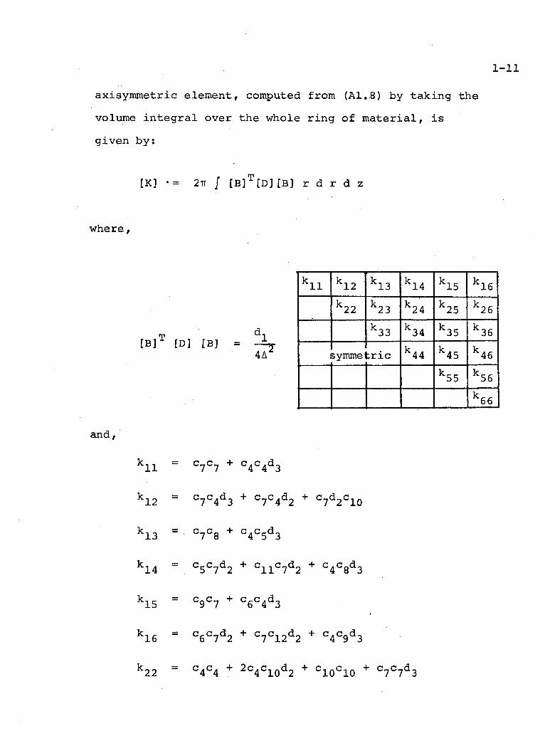
1-11
axisymmetric element, computed from (A1.8) by taking the
volume i n t e g r a l over the whole rin g of material, i s
given by:
[K] •= 2TT / [ B ] T [ D ] t B ] r d r d z
where,
and,
[B] [D] [B] = 1_ 4A
k l l k12 k13 k14 k15 k16 k22 k23 k24 k25 k26
k33 k34 k35 k36 l 5ymme : r i c k44 k45 k46
k55 k56 k66
'11 C7 C7 + C 4 C 4 d 3
'12 c 7 c 4 d 3 + c 7 c 4 d 2 + c 7 d 2 c 1 0
' 1 3 C7 C8 + c 4 C 5 d 3
'14 c,- c—d „ + c,,c»d» + c.c «d„ 5 7 2 11 7 2 4 8 3
'15 C9 C7 + C 6 C 4 d 3
'16 c 6 C 7 d 2 + c7 C12 d2 + C 4 C 9 d 3
'22 c 4 c 4 + 2 c 4 c 1 0 d 2 + c 1 0 c 1 0 + c 7 c 7 d 3

k23 = c 8 C 4 d 2 + c8 C10 d2 + C 5 C 7 d 3
k24 = C5 C4 + c5 C10 d2 + c l l c 4 d 2 + C10 C11 + c 7 C 8 d 3
k25 = C 4 C 9 d 2 + C9 C10 d2 + c 6 C 7 d 3
k26 = C4 C6 + c6 c10 d2 + c4 C12 d2 + C10 C12 + c 7 C 9 d 3
k33 = C8 C8 + C 5 C 5 d 3
k34 = c 5 C 8 d 2 + c 8 C l l d 2 + C 5 C 8 d 3
k35 = C9 C8 + C 6 C 5 d 3
k36 = C6 C8 d2 + c8 C12 d2 + c 9 C 5 d 3
k44 = C5 C5 + 2 c 5 C l l d 2 + C11 C11 + C 8 C 8 d 3
k45 = C5 C9 d2 + C 9 C l l d 2 + C 6 C 8 d 3
k46 = C5 C6 + C 6 C l l d 2 + C5 C12 d2 + C11 C12 + C 8 C 9 d 3
k55 ~ C 9 C 9 + C 6 C 6 d 3
k56 *" C 6 C 9 d 2 + C12 C9 d2 + C 6 C 9 d 3
k66 = C6 C6 + 2 c 6 C 1 2 d 2 + C12 C12 + C 9 C 9 d 3
E ( l - V ) v
and d, = — — ~ , d 9 = , 1 (1-v) (l-2v) ^ 1-v
. . 1.-.2V ' ' d
3 2(1-v)
In evaluating the element s t i f f n e s s matrix,
term by term exact integration was performed.

1-13
Coming t o the body f o r c e s ,
{ F } p = - / [ N ] T {p} dv (A1.9)
Fo r body f o r c e s due t o g r a v i t y o n l y , {p} = { P Q }
I f the body f o r c e s are c o n s t a n t i t can be shown t h a t [ 3 2 ] ,
{F\} - {P } = {F M} = - 2TT r A/3 , where
p 3 P
( r . + r . + r ) r = 1 3 m (A1.13)
A l though the above r e l a t i o n i s not e x a c t , i t i s found to
g i v e q u i t e a c c u r a t e r e s u l t s .
Computer Programme
The s u b r o u t i n e f o r computing element s t i f f n e s s
m a t r i x reads e lement p r o p e r t i e s and n o d a l c o o r d i n a t e s as
i n p u t d a t a and genera tes the m a t r i x f o r each e lement which
i s then s t o r e d i n a tape by the main programme. The
programme then c a l l s the s u b r o u t i n e which forms the assemblage
s t i f f n e s s m a t r i x by s u p e r p o s i n g i n d i v i d u a l e lement e f f e c t s .
1-14
The element nodal forces due to a body force i s then calcu
lated for each element by using equation (A1.13). Super
position of r e s u l t s leads to the assemblage nodal forces
due to the body force. The external nodal forces (reactions)
are then added to nodal body forces to obtain the s t r u c t u r a l
load matrix. The load displacements equations for the whole
structure i s then solved to give the nodal displacements
by using the 'banded1 property of the matrix.
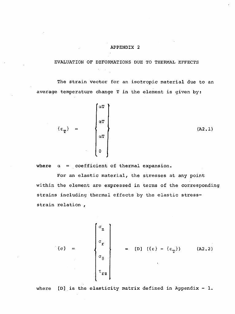
APPENDIX 2
EVALUATION OF DEFORMATIONS DUE TO THERMAL EFFECTS
The s t r a i n v e c t o r f o r an i s o t r o p i c m a t e r i a l due to an
average temperature change T i n the e lement i s g i v e n b y :
aT
{ E T } =
aT
aT
( A 2 . 1 )
0
where a = c o e f f i c i e n t o f the rma l e x p a n s i o n .
Fo r an e l a s t i c m a t e r i a l , the s t r e s s e s a t any p o i n t
w i t h i n the e lement are e x p r e s s e d i n terms o f the c o r r e s p o n d i n g
s t r a i n s i n c l u d i n g therma l e f f e c t s by the e l a s t i c s t r e s s -
s t r a i n r e l a t i o n ,
{a} =
r z
= [D] ({e> - U T } ) ( A 2 . 2 )
where [D] i s the e l a s t i c i t y m a t r i x d e f i n e d i n Appendix - 1.
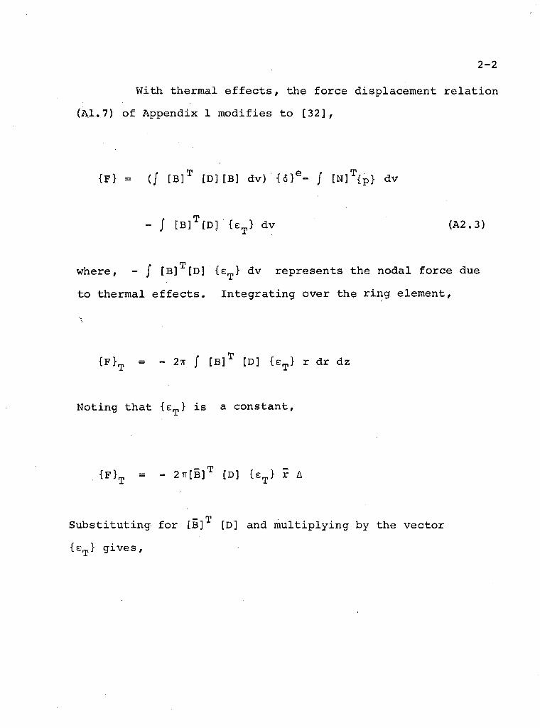
2-2
With therma l e f f e c t s , the f o r c e d i s p l a c e m e n t r e l a t i o n
(Al.. 7) o f Appendix 1 m o d i f i e s to [ 3 2 ] ,
{F} = (/ [ B ] T [D][B] dv) { 6 } e - / [ N ] T { p } dv
- / [ B ] T [ D ] {e T> dv (A2.3)
where, - J [B] [D] {e T } dv r e p r e s e n t s the n o d a l f o r c e due
to t h e r m a l e f f e c t s . I n t e g r a t i n g over the r i n g e lement ,
{ F } T = - 2TT / [ B ] T [ D ] ' { e T ) r dr dz
N o t i n g t h a t {e T > i s a c o n s t a n t ,
{ F } T = - 2TT[B] T [D] {e T> r A
— T
S u b s t i t u t i n g f o r [B] [D] and m u l t i p l y i n g by the v e c t o r
{e } g i v e s ,
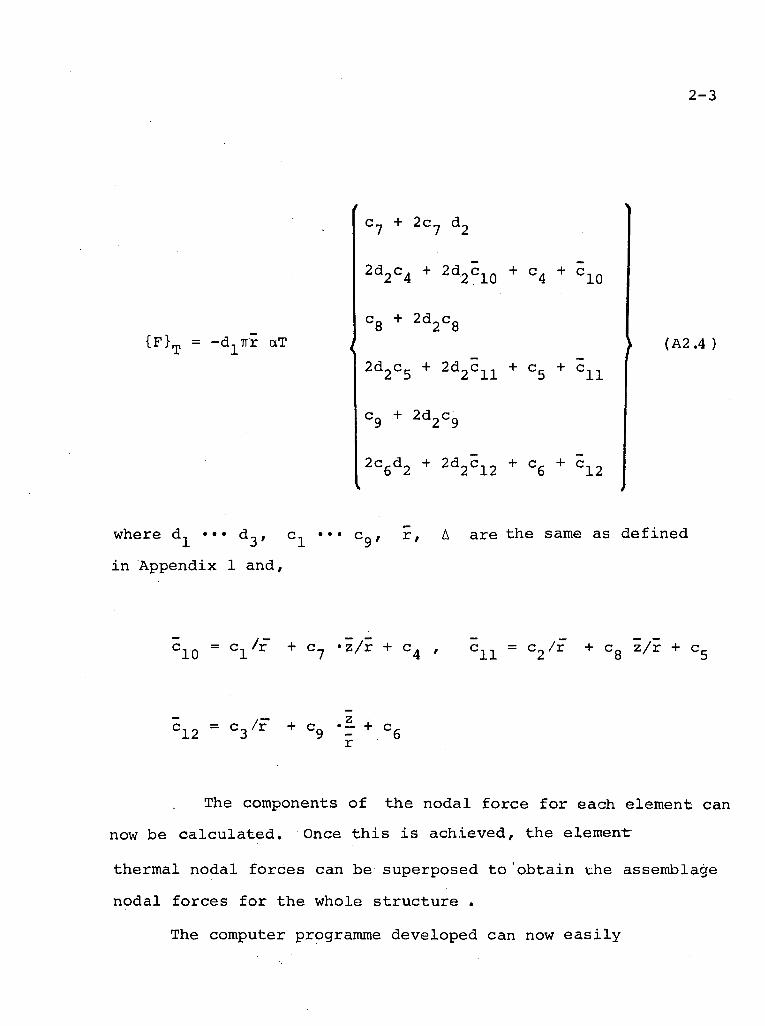
2-3
{ F } T = -d^TTr aT
c 7 + 2 c ? d 2
2 d 2 c 4 + 2 d 2 c 1 0 + c 4 + c 1 Q
c 8 + 2 d 2 C 8
2 5 2 11 5 11
c 9 + 2 d 2 c 9
2 c 6 d 2 + 2 d 2 c 1 2 + c 6 + c 1 2
( A 2 . 4 )
where d^ ••• d 3 , c j_ *'* c 9 ' A a re the same as d e f i n e d
i n Appendix 1 and ,
C 1 0 = C ± / * + °7 *^/r + C 4 ' c l l = c 2 / r + c 8 Z / / r + °5
5 1 2 = C 3 / F + C " Z 9 - + C 6 r
The components o f the n o d a l f o r c e f o r each element can
now be c a l c u l a t e d . Once t h i s i s a c h i e v e d , the element-
therma l n o d a l f o r c e s can be superposed t o ' o b t a i n the assemblage
n o d a l f o r c e s f o r the whole s t r u c t u r e .
The computer programme deve loped can now e a s i l y
2 - 4
be modified to incorporate these thermal nodal forces while
forming the s t r u c t u r a l load matrix. The solution of the f i n a l
load displacement equations to obtain the nodal displacements
follows'the same procedure as that used for the body' force.