Embed Size (px)
Citation preview
International Journal of Fracture, Vol. 11, No. 1, February 1975 Noordholf International Publishing- Leyden Printed in The Netherlands
93
On the fracture of highway pavements
S I - T S A I L I N and E. S. F O L I A S
Department of Civil Engineering, University of Utah, Salt Lake City, Utah 84112, U.S.A.
(Received September 11, 1973)
A B S T R A C T Using a model of a single layered foundation to describe a highway or an airfield pavement and an integral formulation, the problem of a pavement containing on-the-top layer a crack of finite length 2c is solved for the stress distribution around the crack tip. The analysis shows that the stresses possess the usual 1/e ½ singular behavior which is character- istic of crack problems. Furthermore, it is found that the stress intensity factor decreases as the magnitudes of the two foundation parameters increase. Finally, as the foundation presents more resistance to shear deformation, the critical load for crack initiation increases.
Nomenclature
2¢
D E, Es G Y, V s
Yv, Ys h H
g q (x, y)
Po V(y c), ~P)
MI° , MIv) W(x , y)
y)
y)
r*, 6*, m*, r,
= crack length = Eha/[12(1 - v2)] = flexural rigidity of a plate = Young's modulus of plate and elastic foundation, respectively = shear modulus of plate = Poisson's ratio of plate and elastic foundation, respectively = specific weights of plate and elastic foundation, respectively = thickness of the plate = thickness of the foundation = the vertical displacement function of the elastic foundation and $ (0) = 1 = gravitational acceleration = lateral load = load intensity of the concentrated loads
= shear forces as defined in text
= bending moments as defined in text = transverse deflection of a plate in bending = transverse deflection of a continuous plate which has not been weakened
by the crack = transverse deflection of a plate involving perturbations induced by the
presence of the crack = limr_.o+ Wt°(x, y), WtS)=limy-.o - WtO(x, y) = generalized elastic characteristic constants as defined in text
X, Y, Z = rectangular coordinates in middle plane of a plate x - X / c , y=- Y/c, z - Z / c y = 0.5772 Euler's constant e, O; ee i° = x + l + iy ( v o -- 1 - -v ax, ay, zxy = stress components
a~ ), a~ c), -xr~(° = perturbation stress components due to the presence of the crack ~b " 6Dmo/h2c2
Pb = stress coefficient
Int. Journ. of Fracture, 11 (1975) 93-106
94 S i - T s a i L in and E. S. Fol ias
)2+ = r 2 + (r 4 _ ~4)-~
~2_ = r 2 _ (r 4 _ ~4)~
k - U6
I. Introduction
It is well known that cracking of asphalt pavements is due primarily to temperature variations and to the constant application of heavy repetitive loads. Initially the effects of the cracks and holes on the riding quality are minor; however, intrusion of water very quickly causes appreci- able swelling of certain subgrades With resulting bumps and a very rough riding pavement. On sandy subgrades, for example, due to material falling into the crack, severe dips can occur. Furthermore, the high stress concentrations at the tip of the crack coupled with the frost heave can result in additional cracking and spalling, with pot holes as the final result.
Consequently, considerable maintenance is usually required for crack filling and repairs. However, crack filling often has to be repeated annually, for the sealing materials which are used cannot adequately accommodate seasonal and long term contraction. Cracking, therefore, is considered to be economically very serious and it represents a major problem that pavement designers must face.
Up to now, m ~ t of the highway pavement design methods are based largely on experience expressed in the form of correlation between soil type, material properties, temperature, traffic volume and thickness. Although these methods have in the past met with reasonable success, rapid increases in the number of heavy axle loads and variety of subgrades that must support them have outrun past experience to a great extent. It is evident, therefore, that an adequate and reliable theory becomes essential.
While ~t is recognized that the problem is extremely difficult due to its many parameters which are involved, nevertheless the application of the principles of modern fracture mechanics will lead to a better understanding and finally, to a practical solution of this complex phenome- non. "
In this paper, the authors attempt to study only one aspect of this phenomenon, namely, the effect which the weight of a vehicle has on the propagation of an already existing, on the high- way pavement, crack.
2. Generalities
Analyses of plates resting on foundations usually fall into two groups. The first group follows the well known theory of Winkler and Zimmermann [1] in which the elastic foundation is considered as a system of separate unconnected springs. Such a hypothesis simplifies consider- ably the analysis of structures on elastic foundations and leads frequently to incorrect results. The second group follows the theory in which one describes the physical properties of the natural foundation more accurately by the hypothesis that the foundation is an elastic isotropic semi-infinite space [2]. Here again, such a hypothesis leads to cumbersome calculations and therefore the method becomes impractical.
Recently a new theory based on Vlasov's general variational method [-3] has been proposed [4]. This theory considers the elastic foundation as a single or double layer model whose properties are described by two or more generalized elastic characteristics. The advantage of this theory is that it is more accurate than the theory of Winkler and Zimmermann and simpler than the theory of the elastic semi-infinite space.
The characteristics of the fracture of pavements on a Winkler-Zimmermann foundation have been investigated and the results are reported in [5]. In this paper, the authors consider the analogous problem with a single layer foundation.
Following [4], the differential equation governing the displacement function W ( X , Y) of a plate resting on single layered elastic foundation is
V4W - 2r *e V2W+ 6"4W+ m* --~ew - q (2.1) 6~t 2 D
Int. Journ. of Fracture, 11 (1975) 93-106
On the fracture of highway pavements 95
with the quantities r*, 6" and m* as constants defined by *
r , 2 _ E* f n ~k a (z)dz (2.2) 4(1 +vs*)D o
6 *4 = ( l_v ,2)D {01(z)}2dz (2.3)
m* = ( ~ + '~ fn ~k2(z)dz) o --D (2.4)
and where we have introduced the following definitions Es
(2.5) E* = 1 - v s
vs (2.6) ~ - 1-v~
The usual moment components Mx, Mr, and Mxr are defined in terms of the displacement function W as :
FO2W ~ 2 W ] NIx= - DL-~- ~ + v - ~ A (2.7)
M r = L w+ v c3X2 j (2.8)
dZw Mxr = - D ( l -v )OXOY (2.9)
and their corresponding stress components as:
EZ VO2W ~2W] O'x/, = ( l ~ 2 ) L ~ - ) - q- v t 3 y 2 j
Ez F w+ o,b = ( 1 - v ~)LaY s v-~-~A
82W Zxr b = - 2 GZ 8X ~-----~.
(2.10)
(2.11)
(2.12)
3. A cracked plate on a single layered foundation
Formulation of the problem
Consider an infinite elastic plate which rests on a single-layered elastic foundation and con- tains a finite, through the thickness, crack of length 2c. The plate is subjected to two equal concentrated lateral static loads of intensity P0 with corresponding points of application (0, L, - h ) and (0, - L , - h ) (see Fig. 1). Furthermore, in order to simplify our mathematical complexities, we assume that L >> c.
* It is assumed that no horizontal displacements occur in the elastic foundation and that the vertical displacement is given by a single function q/(z). From Ref. [4], a typical function is
~,(z) - sinh [r,(H-z)]
sinh Jr, H]
where r, is a coefficient determining the variation with depth of the displacements.
Int. Journ. of Fracture, 11 (1975) 93-106

96
TOP VIEW
%
"7 L
, I,
O %
SIDE VIEW ? Z H /
1//)/////- / 1 / i I / I N / x / I N i i i / E / f , / ~ , -
Figure 1. A cracked plate on a single layered foundation.
----~ X
X
Si-Tsai Lin and E. S. Folias
It .is found convenient at this stage, to introduce the following dimensionless variables, i.e.,
x - X / c , y - Y / c , z - Z / c , 1 -L /c ,
also define
r = cr*, fi = c6* _ (3.1)
The differential equation governing the displacement function W(x, y), with x and y as dimensionless rectangular coordinates, may now be written in the form
P0 V 4 W - 2 r2V 2 W+ 64W = c* --~ 6(x) { 6 ( y - l) + 6 (y +/)} (3.2)
where V 4 and V 2 are respectively the biharmonic and Laplacian operators, and 6(.) is the Dirac Delta function.
The boundary conditions along the crack are those of free edges. However, inasmuch as classical bending theory is used, only two boundary conditions along the crack may be satisfied. In particular, one must require that the normal moment and equivalent vertical shear vanish, i.e.,
M y lim / = 0 for l < x < l (3.3)
lyl s 0 Vr
In addition, it is required that the function W and all its partial derivatives up to the third order be continuous for all x and y, except for points on the segment - 1 < x < 1 and y = 0. In order not to lose any generality, one may assume that at infinity the plate is loaded in some general manner.
Suppose now that one has already found a particular solution* satisfying (3.2) but there is a residual normal moment M r and equivalent vertical shear Vy along the crack I xl < 1 of the form
M~p) = Dmo c2 (3.4)
Vy(P) = 0 (3.5)
where, for simplicity, mo will be taken to be a constant. *~'
* See Section 5 for the particular solution. ** For mo non-constant , also see remarks in Section 5.
Int. Journ. of F'racture, 11 (1975) 93-106
On the fracture of hiohway pavements 97
Mathematical statement of the problem
Assuming therefore that a particular solution has been found, we need to find a function W to) (x, y) such that it satisfies the homogeneous part of the partial differential equation (3.2) and the fol- lowing boundary conditions:
at y = 0 and Ixl < 1
D FO2W(~) 02W~'] _ Dmo (3.6) M ~ C ' ( x ' 0 ) - - c 2 L-~f + v Ox 2 Jl,l=O c2
and
83W c) ~3 W(c) 1 Vy(C)(x'0)= - c D-3 L 8ya + (2 -v ) 0x2Oy ]lyl= 0 = 0 (3.7)
at y = 0 and [xl > 1 - 0" O" -1
lim (W~)) -- 03 ~ (W_ - 0 (n = 0, 1, 2, 3) (3.8) lyl~O
To complete the formulation of the problem, we require that the displacement function WtC)(x, y) together with its first partial derivatives be finite at infinity. These restrictions guarantee finite displacements and stresses far away from the crack.
4. Construction o f the solution
Method of solution
We construct the following integral representation which has the proper behavior at infinity
= f o {P1 exp[-(s2+22)~lYl]+P2 exp [-(s2+22-)½IYl]} cos(xs)ds (4.1) W~CJ(x, y+-)
where P1 and P2 are arbitrary functions of s to be determined from the boundary conditions and the ___ signs refer to y > 0 and y < 0, respectively.
Assuming therefore that one can differentiate under the integral sign, one finds by substituting Eqn. (4.1) into (3.7) that
-T- { [~2 _ (2 - v)s 2 ] ~Px (s)+ [f12 _ (2 - v)s 2] tiP2 (s)} cos (xs)ds = 0 (4.2) 0
where for simplicity we let
= (s 2 + 2 2)~ (4.3)
ti --= (s 2 + 22-)½ (4.4)
Equation (4.2) may be satisfied if one chooses
P1 (s) = [ti2 --(2-- v)s 2] tiP(s) (4.5) P2 (s) = - [ct 2 -- (2 - v)s 2] ~P (s) (4.6)
where the function P (s) is still largely arbitrary. Similarly, substituting (4.1) into (3.6) and utiliz- ing Eqns. (4.5) and (4.6) one obtains
-- {(~Z--vsZ)[ti2--(2--v)sZ]ti--(ti2--vs2)[~2--(2--v)sZ]~}p(s) cos(xs)ds = too, 0
for Ix l < l (4.7)
Next, it can easily be shown that all the continuity conditions may be satisfied if one considers the following expression to vanish
Int. Journ. o f Fracture, 11 (1975) 93-106

98 Si-Tsai Lin and E. S. Folias
f o~ f l (~ 2 - f l 2 )p ( s ) cos ( x s )d s=O for I x l > l (4.8)
Reduction to single integral equation
Because we are unable to solve dual integral equations of the type discussed in the previous section, we will therefore reduce the problem to that of the solution of a singular integral equation. If one now lets
u(x) = c~fl(eE-fl2)p(s) cos(xs)ds for Ixl < 1 (4.9) o
Then by Fourier inversion 2 1
P(s) - xctfl(~ 2_fl2) I0 u(4) cos (s4)d~ (4.10)
where the function u (4), due to the symmetry of the problem is an even function. Thus, formally, substituting (4.10) into (4.7) one, after changing the order of integration and rearranging has
ix L(2+,A_,lx-41)u(~)d~ = -moTzX for Ixl < 1 (4.11) - 1
where the kernel L(2+, 2_, I x -4 I) is given by the expression
L(2+, 2_, lx_4[) = f°° { (~2--vs2)[f12--(2--v) s2] o
_ ([32 _ vs 2) [~2 _ (2 - v) s 2] ~ sin (x - 4) s ds (4.12)
whose asymptotic form for small 2+, 2_'s is
1 { -~6 [v(2-v) (5- 12y+ 12 In 2) L(2+, 2_, 1(I) = (1-v)(3+v) ~ +
+ ( 3 - 4 7 + 4 In 2 ) - 8 v ( 1 - 2 7 + 2 In 2)](22 +22)
+¼(3v+l)(1-v) 24+ In 2+-24- l n 2 - 2 2 + _22_ + ( l - v ) ~---T222+22-- In 2~} 2+ - 2 _
+¼(1 + 3v)(1 - v)(2 2 +22_)( In ( + ... (4.13)
We require now that the solution u (4) be H61der continuous for some positive H61der index # for all x in the closed interval [ - 1 , 1]. In particular, u(4) is to be bounded near the ends of the crack.
Solution of the inteoral equation for small 2+ and 2_
Case I. 6,~ r < 1 The asymptotic form of the kernel becomes:
1 L(2+, 2_, I¢1) = (1-v)(3+v) ~ + { - ~ [ v ( 2 - v ) ( 5 - 127+ 12 In 2)
+ ( 3 - 4 7 + 4 In 2)--8v(1-27+2 In 2)]r 2
+¼(3v+ 1)(1 --v)(2 In r+ In 2) r 2}
+½(1 + 3v)(1 - v ) r 2 ( In ( + ... (4.14)
Int. Journ. of Fracture, 11 (1975) 93-106
On the fracture of highway pavements 99
ThUs, following the same method of solution as that described in Ref. [6], one may let ~
u(4) = ( 1 - 4 2 ) ~ [ a l + a 2 r 2 ( 1 - 4 2 ) + . . .] ; Ill < 1 (4.15)
where the coefficients Ai's are functions of r but not of ~. Substituting (4.15) into (4.11) and making use of the relations given in the Appendix, find,
by equating coefficients, that:
A1 = mo(12-~r2){{12(1-v)(3+v)+ { - ¼ [ v ( 2 - v ) ( 5 - 1 2 7 + 12 In 2)+
- 2 ( 3 - 4 7 + 4 In 2)+ 1 6 v ( 1 - 2 7 + 2 in 2)] + 2a(3 v+ 1)(1 -v)(1 - i n 2 + 2 In r)} r2+
+ {6-~[v(E-v)(5- 127+ 12 In 2 ) + ( 3 - 4 7 + 4 ln2) - 8 v ( 1 - 2 7 + 2 In 2 ) ]+
-~2(3 v+ 1)(1 - v)(-~- In 2 + 2 In r)} r4}} -1 {4.16)
Case II. r = k6 < 1 The asymptotic form of the kernel now becomes
L(2+, 2_, I~])= (1--v)(3+ v) ~ + I -:--~ [v (2 -- v) (5 - 1 2 7+ 12 In 2)+
+ ( 3 - 4 7 + 4 In 2 ) - 8 v ( 1 - 2 7 + 2 In 2)]k262+
[ 2k 4 - 1 k 2 +(k 4 - 1) ½ ] 62 +¼(3v+ 1)(1 - v ) 14(k4 - 1)~ In k2 - (k4_ 1) ½ + 2k 2 In 6_ +
(1 + v) k 2 + (k 4 - 1) ½ + 4(k4 - 1) ~ In k2_(k4_ 1) ~ 62 ~ (+½( l+3v) (1 -v )k262 . ( In ( + ...
and if again we let
u (4) = (1 - ~2)½ [B1 + B2 62 (1 - 42) + . . . ]
then
B 1 =
(4.17)
(4.18)
1 k 2 + ( k 4 - 1 ) ½ m o (1 - v)(3 + v) + 8 (k 4 - 1) ½ In k2 _ (k 4 _ 1) ~ [(1 + v) + ¼(3v + 1)(1 - v)(2k 4 - 1)] 62 +
- ~ 6 [-v(2- v ) ( 5 - 1 2 7 + 12 In 2 ) + ( 3 - 4 7 + 4 In 2 ) - By(1-2 7 + 2 In 2)+
- 2 ( 1 + 3 v ) ( 1 - v ) ( 1 - 2 In 2)]k262+¼(3v+l)(1-v)k2(ln 6)62+
3 k 262 + ( 1 - v ) ( 3 + v ) 4 _ 3 k 2 6 2
- ~ 2 [v (2 - v) (5 - 1 2 7 + 12 In 2 ) + ( 3 - 4 7 + 4 In 2 ) - 8 v ( 1 - 2 7 + 2 In 2)+
(4.19)
k 464 - 2 ( l + 3 v ) ( 1 - v ) ( ½ - 2 In 2)] 4 _ 3 k 2 6 2 +
3 k 2 + (k 4 - 1) ½ k 2 t~ 4 + 16(k4_1) ~ In k2_(k4_1)~ [ ( l+v)+¼(3v+l ) (1 -v ) (2k4-1 ) ] 4 _ 3 k 2 6 2 +
k 4 64 }- 1
+ 3 ( 3 v + 1 ) ( l -v ) 4 _ 3 k 2 6 2 (In 6)+ ...
The displacement function W
For both of above cases, we obtain
Int. Journ. of Fracture, 11 (1975)93-106
100 Si-Tsai Lin and E. S. Folias
P( s )= (22+_22_)(s2+22+)½(s2+22) ½ 01 + 3 0 2 A 2 ~ +
D A 4Ja(s) (4.20) + 1 5 a - - ~ - + - - .
where in Case I,
D i = Ai, i = 1, 2, 3 . . . .
in Case II,
D i = B i i = 1, 2,3 . . . .
and A = r (4.21)
and A = 6 (4.22)
Therefore, a substitution of (4.20), (4.5), (4.6) into (4.1) will determine the bending deflection W (c) as follows:
W(c)(x'Y±) = o --(1--v)(s2+)~2) ½+ ~ - ~ - 2 ~ - ] e x p [-(s2+;~2+)½lyl] +
(1-v)2 - [-(l-v)(s2+22_) ½+ (sZ+22_) ½ j e x p [-(sZ+22_)½1Yl]}x X { D1JI(s)'JI-s 3D:A2Jz(s)~ + 15Da A'~J3~)~ + "'" }cos(xs)ds(22+-22) (4.23)
The stress field ahead of the crack tip
In view of the displacement function W, the bending stresses at the surface z = - h/c may now be computed as
[ . 0 - -
0.8
]i o.s I I ¢ 0 . 4 -
0 . 2 -
0 I 0 0.2
Figure 2. Stress coefficient versus r.
Int. Journ. of Fracture, 11 (1975) 93-106
CASE I < ~ ¢ r < l v =1/3
I I I I 0.4 0.6 0.8 1.0
r
On the fracture of hiohway pavements 101
Pb ( 3 - 3 v 01-Vcos502)+O(eO) = - 4 - - cos - - - T -
1 - v 50) Pb ( l l + 5 v cos_02 + cos + O(e °) trr - (Ee) ~ \ 4 T -2-
Pb ( 7+V 0 1 - v 50) zxy- (2e) ~ - - - ~ sin E 4 sin~- +O(e °)
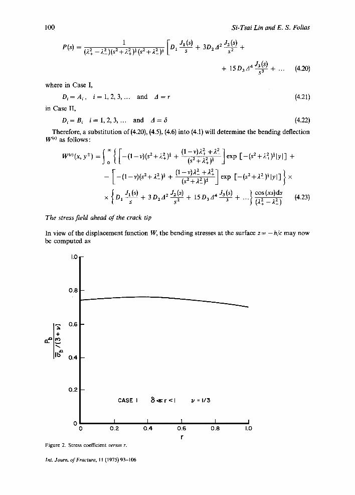
where the stress coefficient Pb is given by (i) for 6 ~ r < l
-
(4.24)
(4.25)
(4.26)
fib (12_ar2) {12+ {-¼Iv(2-v) (5-12 7+ 12 In 2)+ (3Tv)
- 2 ( 3 - 4 7 + 4 In 2)+ 16v(1 -27+2 In 2)] +
r 2 +-~(3 v+ 1)(1-v)(1-1n 2+2 In r)} (1-v)(3+v) +
+ {~ [v (2 - v)(5-127+ 12 In 2 ) + ( 3 - 4 7 + 4 In 2 ) - 8v (1 -27+2 In 2)] r 4 } - 1
- A ( 3 v+ 1)(1- v)(~-ln E+E In r)} (1 -v)(3+v) + "'" (4.27)
Notice that 6 does not appear in Eqn. (4.27) for it is negligible. A plot of this is given in Fig. 2. (ii) for r=k6 < 1, where k is a real constant
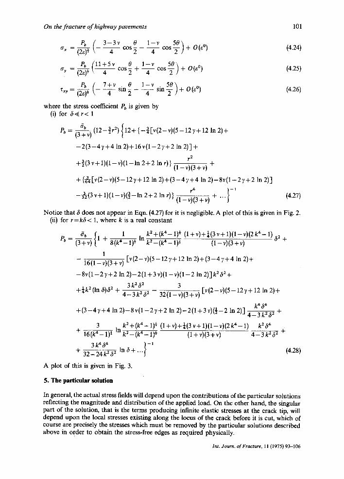
tY b { 1 kE+(k4-1) ½ (l+v)+¼(3v+1)(1-v)(2k4-1)62 P b - (3+-V) 1 + 8(k4_1)~ In kE_(k4_l)½ (1-v)(3+v) +
1 - 16(1-v)(a+v) [v (2 - v) (5 -12 7 +12 In 2 ) + ( 3 - 4 7 + 4 In 2)+
- 8 v ( 1 - 2 ) , + 2 In 2 ) -2(1+3 v)(1-v)(1-2 In 2)] k262+
3 k 262 3 +¼k2 (In 6)62 + 4-3k262 32 (1 - v) (3 + v) [v (E - v) (5 - 12 7 + 12 In 2)+
k 464 + ( 3 - 4 7 + 4 In 2 ) -8 v(1-2 7+2 In 2)-2(1 +3 v)(½-2 In 2)] 4 - 3 k262 +
3 kE+(k4- 1) ~r (l+v)+¼(av+l)(1-v)(2k4-1) k264 + 16(k4_1) ½ In kE_(k4_l)½ (l+v)(3+v) 4-3k262 -~
3 k 4 6 4 } - 1 + 32- 24 k 262 In 6 +. . . (4.28)
A plot of this is given in Fig. 3.
5. The particular solution
In general, the actual stress fields will depend upon the contributions of the particular solutions reflecting the magnitude and distribution of the applied load. On the other hand, the singular part of the solution, that is the terms producing infinite elastic stresses at the crack tip, will depend upon the local stresses existing along the locus of the crack before it is cut, which of course are precisely the stresses which must be removed by the particular solutions described above in order to obtain the stress-free edges as required physically.
Int. Journ. of Fracture, 11 (1975) 93-106
102 Si-Tsai Lin and E. S. Folias
1.0
0 . 8
l + 0.6
I ,# 0.4
CASE II r = k ~ < 1 v -- I / 3
0.2
o I I I I I 0 0.2 0.4 0.6 0.8 1.0
8 Figure 3. Stress coefficient versus ft.
k - - 0
To get the particular solution, one has to solve the following differential equation:
V 4 Wry)_ 2r 2 V2 Wtp) + ~4 W(p) = Po c4 D 6 ( x ) { 3 ( y - l ) + 6 ( y + l ) } (5.1)
with boundary conditions
lim M iv) (x, y) = 0 X ' ' ~ at)
~ + ~ (5.2) and
lim V tp> (x, y) = 0
' . . . . (5.3) Suppose one chooses the integral representation
W <v) = R (s, y) cos (xs) ds (5.4) o
then substitutes into (5.1), and follows the Green's function method of [12], without going into details, will find
W(V> = Po c4 2rr0(22 _,~2_) {Ko I-2+ (x2+ ly--/12)+] + Ko I-2+ (x2+ lY+/12) +] +
-- Ko [g_ (x2 + l y - ll2)+] -- Ko[R_ (x2 + ly + ll2)½] } (5.5)
It follows at y = 0 and Ixl < 1
M~P~Ix, O) = Omo (5.6) c 2
Int. Journ. of Fracture, 11 (1975) 93-106

On the fracture of highway pavements 103
where
m o
and
Po ca ~ ( l - -v) [1 2x2 7{2+K,[2+(x2+I2)~]+ 27~D(22--22_)l(x2+12) ½ x2+12 3
12 + VX2 I - 2_ K I [-2_ (x 2 + 12) ½] } + x2 + 12 {22+ K 0 [-2 + (x 2 + 12) ~] -- 22 K 0 [-2_ (x 2 + 12) ~3 }
) (5.7)
o) = o . (5.8)
Now, since we have already assumed that 1 ,~ l, it is easy to see that the above bending moment (along the crack) is approximately a constant, i.e., -Dmo/c 2. Alternately, as an engineering approximation, one may think of the quantity ( - Dmo/C 2) as an upper bound, or lower bound, or even a mean value of the precise bending moment along the crack in order to obtain an estimate of the stresses in the vicinity of the crack.
Furthermore, if one wants a more accurate result than that of a uniform residual moment, he must expand mo, for Ix[ < 1, in the form Y.nan X2n (even power because of the symmetry of the problem), and again our previous method of solution will still be applicable. Of course, the coefficients A, and B, in this case may change, but the character of the solution will still remain the same.
Critical loading
Following the concepts of the Theory of Fracture Mechanics, one may make an energy balance* to derive** the following approximate fracture criterion for crack initiation.
For r = k6
2 ( 9 - 7 v ) ( 3 + v ) h 2 I ( l r K 2 ) l = - - a* cos-1 exp IJ (5.9) Poo,.,o., (33+6v_7v2)(l+v) c 2 8 O-.2c
where K = fracture toughness (of the top layer),
f t . = O-yield + (Oyield + O-ultimate)/2 (of the top layer) (5.10) - 2
I k2+(k4-1) ½ ( l+v)+¼(3v+l)(l-v)(2k4-1) 62 In ~ _ + I = 1 + 8(k4_i)~ (k4_1) ~ O _ ~ ) ~ + ~ j
1 - I v ( 2 - v ) ( 5 - 1 2 7 + 12 In 2 ) + ( 3 - 4 7 + 4 In 2)+
16(1-v)(3+v)
- 8 v ( 1 - 2 7 + 2 In 2)-2(1 + 3v) (1 -v) (1 -2 In 2)] k262 +¼(In 6)k262 + 3 k 2 6 2
4 - 3 k 2 6 2
3 - [ v ( 2 - v ) ( 5 - 12 7+ 12 In 2 ) + ( 3 - 4 7 + 4 In 2)
32(1-v)(3+v)
k 4 64 - 8 v ( 1 - 2 7 + 2 In 2 ) -2 (1+3v) (½-2 In 2)3 4_3k262 +
3 k2 + (k4 -1 ) ½ (l+v)+¼(3v+l)(1-v)(2k4-1) k264 + In
16(k4-1) ½ k 2 - ( k 4 - 1) ½ ( l+v)(3+v) 4 - 3 k262 3 k 4 ~ 4 . / - 1
+ 32_24k262 In 6+. . . (5.11)
* The approach is based on a corollary of the First Law of Thermodynamics and was first applied to the phenomenon of fracture by Griffith [13]. ** For more details see reference [-14].
Int. Journ. of Fracture, 11 (1975) 93-106
104 Si-Tsai Lin and E. S. Folias
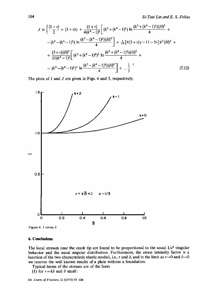
{ ~ ( l + v ) F 2 (k2+(k4-1)~)(61)2+ J - + (1 + v)y + 4~4--Z-]-)~ [(k + (k 4 - 1) ½) In
4
- ( k 2 - (k 4 - 1 ) ~) In (k2- tk4 4 1)½)(6/)2] + ~6 [4(3 + v ) 7 - 1 1 - 5v]k2(61) 2 +
(3+v)(6/) 2 [--. 2 - 4 . . . . + ( k4-1)½)(602 + 3-~(k~-~_~))~L(g +(k -1)~) ~ In (k2 4 +
/ - 1 - ( k 2 - ( k 4 - 1 ) ½ ) 2 In (k2-(k441)~)(61)2 ] + ...~
The plots of I and J are given in Figs. 4 and 5, respectively.
(5.12)
[ . 5 --
1.0
0 . 5 -
0 0
Figure 4. I versus 6.
k = 2 k I
= 0
r = k ~ < l v = l / 3
I I I I I 0.2 0.4 0.6 0.8 1.0
8
6. C o n c l u s i o n s
The local stresses near the crack tip are found to be proportional to the usual 1/e ¢ singular behavior and the usual angular distribution. Furthermore, the stress intensity factor is a function of the two characteristic elastic moduli, i.e., r and 6, and in the limit as r-oO and 6--*0 we recover the well known results of a plate without a foundation.
Typical terms of the stresses are of the form (1) for r=k6 and 6 small:
Int. Journ. of Fracture, 11 (1975) 93-106
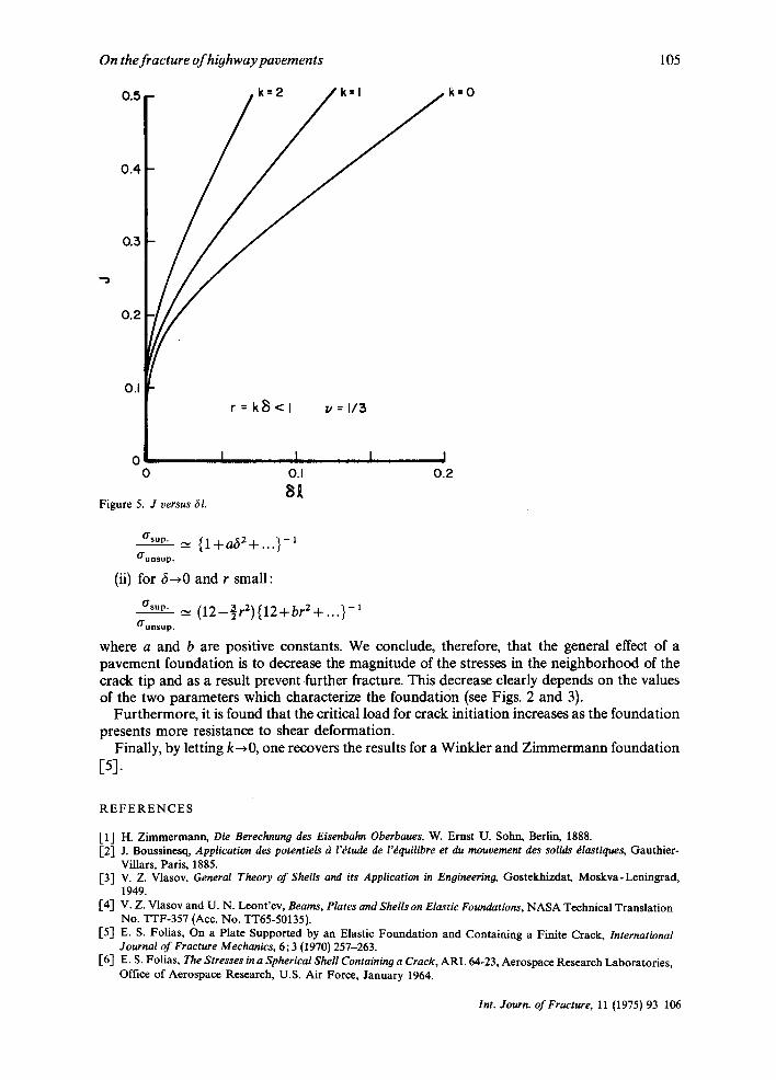
On the fracture of hiohway pavements 105
0.5
0.4
0.3
0.2
0.1
r = k ~ < l ~=1 /3
0 I I I I 0 O.I 0.2
al Figure 5. J versus ~l.
k=O
O'sup • ~ { l + a ~ 2 + . . . } -1
¢Tunsup.
(ii) for 6 ~ 0 and r small:
sop 02_ r2){12+br2+...}-i O'unsup.
where a and b are positive constants. We conclude, therefore, that the general effect of a pavement foundation is to decrease the magnitude of the stresses in the neighborhood of the crack tip and as a result prevent further fracture. This decrease clearly depends on the values of the two parameters which characterize the foundation (see Figs. 2 and 3).
Furthermore, it is found that the critical load for crack initiation increases as the foundation presents more resistance to shear deformation.
Finally, by letting k~0 , one recovers the results for a Winkler and Zimmermann foundation [5].
R E F E R E N C E S
[1] H. Zimmermann, Die Berechnung des Eisenbalm Oberbaues, W. Ernst U. Sohn, Berlin, 1888. [2-[ J. Boussinesq, Application des potentiels ~ l'~tude de l'~quilibre et du mouvement des solids ~lastiques, Gauthier-
Villars, Paris, 1885. [3] V. Z. Vlasov, General Theory of Shells and its Application in Engineering, Gostekhizdat, Moskva-Leningrad,
1949. [4-[ V. Z. Vlasov and U. N. Leont'ev, Beams, Plates and Shells on Elastic Foundations, NASA Technical Translation
No. TTF-357 (Acc. No. TT65-50135). [5] E. S. Folias, On a Plate Supported by an Elastic Foundation and Containing a Finite Crack, International
Journal of Fracture Mechanics, 6; 3 (1970) 257-263. [6-[ E. S. Folias, The Stresses in a Spherical Shell Containing a Crack, ARL 64-23, Aerospace Research Laboratories,
Office of Aerospace Research, U.S. Air Force, January 1964.
Int. Journ. of Fracture, 11 (1975) 93-106

106 Si-Tsai Lin and E. S. Folias
E7] s. H. Do and E. S. Folias, On the Steady-state Transverse Vibrations of a Cracked Spherical Shell, International Journal of Fracture Mechanics, 7; 1 (1971) 23-37.
[8] D. D. Ang, E. S. Folias and M. L. Williams, The Bending Stress in a Cracked Plate on an Elastic Foundation, Journal of Applied Mechanics, 30 (1963) 245-251.
[9] E. S. Folias, Cracked Spherical Shell, Journal of Mathematics and Physics, 44; 2 (1965) 164-176. [10] A. Erd61yi et al., Tables oflntegral Transforms, Vols. I, II. McGraw-Hill Co., New York, 1954. Ell] I. s. Gradshteyn and I. W. Ryhzik, Tables of Integrals, Series, and Products, Academic Press, New York, 1965. [12] E. L. Ince, Ordinary Differential Equations, Dover Publications, Inc. New York, 1956. E13] A. A. Griffith, The Phenomena of Rupture and Flow in Solids, Philosophical Transactions, The Royal Society
of London, Ser. A 221, (1920) 163-198. [14] E. S. Folias, On the Theory of Fracture of Curved Sheets, Engineering Fracture Mechanics; 2, 2 (1970) 151-164.
RI~SUMI~ En utilisant un mod~le repr6sentant une fondation ~ simple couche, pour d~crire une route ou un tarmac, et une for- mulation par int~grales, on r~soud le probl~me d'un rev&ement comportant, darts la touche de surface, une fissure de longueur 2c soumise ~ ses extr6mit6s ~ un champ de contraintes d6termin& L'analyse montre que les contraintes pr6sentent le comportement usuel represent6 par 1/e ~, qui est caract6ristique des probl~mes de fissurations. De plus, on trouve que le facteur d'intensit~ des contraintes d~crolt lorsque les grandeurs des deux param~tres caract~risant la fondation s'accroissent. Enfin, lorsque la fondation pr&ente une plus grande r6sistance ~ la d6formation par cisaillement, il s'ensuit un accroissement de la charge critique n~cessaire fi l'amor~age de la fissure.
Z U S A M M E N F A S S U N G Durch Gebrauch eines Modelle~ von einem Fundament mit einer einzigen Schicht zur Beschreibung eines Autobahn- oder Flughafenbelages, und einer Formulierung durch Integrale wird das Problem des Belages, das einen RiB yon endlicher L~inge 2c in der Oberfl~ichenschicht enth~ilt, in Hinsicht der Spannungsverteilung an der Ril3spitze gelSst. Die Analyse ergibt dab die Spannungen das gebriiuchliche 1/e ½ singul~ires Benehmen enthalten was spezifisch fiir Ril3probleme ist. Weiterhin wurde gefunden dab die Spannungsintensit~itsfaktoren abnehmen wenn die Werte der zwei Fundamentparametern zunehmen. Und schliel31ich da das Fundament einen grSBeren Widerstand gegeniiber Quer- verformungen besitzt, nimmt die kritische Last der Ril3auslSsung zu.
Int. Journ. of Fracture, 11 (1975) 93-106