Embed Size (px)
Citation preview

After a short historical review, this paper recallsthe successive steps of the life prediction ofsingle crystal turbine blades, paying attention toa proper modelling of the material, to themechanical aspects in the blades and to theboundary conditions. The code built around theFE solver ZéBuLoN is now able to predict crackinitiation by post-processing of the 3Delastoviscoplastic computations.
■ INTRODUCTION
The lifetime prediction for the critical components of theaeronautical engine, especially the turbine blades, comes atthe final stage of the design, after aerodynamics, after theoptimization of the cooling system, after solving the thermalproblem. The successive steps followed to get a number ofcycles to failure are the definition of the constitutive equa-tions, the computation of stresses and strain under realisticloadings, and the lifetime prediction itself, that is the deter-mination of the number of cycles for crack initiation. Some ofthe authors of the paper have been involved in this processfor 30 years, specially with Snecma, with a need to considerthe problem from metallurgical or mechanical point of view.This paper gives the opportunity to give a review of thevarious tasks to be fulfilled in during the design stage. Onewill successively find :
– three sections on the material element, namely a quickdescription of the materials used in the blades, the consti-tutive equations and the damage model ;
– the application of the models to the blades, with first a dis-cussion of the mechanical model chosen to represent theblade, then a description of the software needed, andfinally some results on real blades.
■ MATERIALS
Sitting just downstream of the burner the blades expe-rience temperatures of more than a thousand degreeCelsius. Progress can be made by means of better designand cooling systems, as shown below, but impressiveimprovements were also made with materials in the lastthree decades. Refractory alloys are needed, and usuallyNi-based alloys present the best performance. Startingfrom polycrystals, collaborative studies between resear-chers and engineers have lead to directionally solidifiedmaterials, then to single crystals. All of them exhibit preci-pitation hardening, due to the γ−γ’ microstructure. Themetallurgical features of such an arrangement have beenstudied for a long time, and studies have been recentlydeveloped in single crystals to bridge the gap between theobservation of the slip systems and the mechanicalmodels (13). On a lower scale, a well know phenomenonis the evolution of the γ’ precipitates from an initially cubicshape toward “rafts”, as shown in figure 1. Specific ther-mal treatments can be derived from this kind of studies,but, amazingly, the knowledge is not strong enough tohave a full micro-macro model taking into account thetwo-phase character of the material, even if the lastattempts are promising, on the experimental side (6) orconcerning more physical models (11, 10). This is thereason why, as shown later, only macroscopic crystallo-graphic models are used for the simulation of the compo-nents in the Finite Element codes.
■ CONSTITUTIVE EQUATIONS
Even if the nickel-based superalloys presented in the previoussection are clearly two-phase materials, this aspect is usuallynot taken into account in the models used for design. Themain reason is that the effect on the mechanical properties ofall the microstructural changes are not fully understood yet.Opposite variations may be due to a change of the volumefraction, the shape of the precipitates, and the local disloca-tion densities in the channels. The current practice uses puremacroscopic models. Polycrystals are modelled with vonMises criterion, and single crystals by a crystallographicapproach. In both cases, viscoplastic constitutive equationsare needed to account for stress redistributions. Isotropic andkinematic isotropic hardening are requested to correctlyrepresent cyclic behaviour. These types of models are descri-bed in textbooks (14, 2). In the following, a short descriptionof the crystallographic model (16) is given.
La Revue de Métallurgie-CIT/Science et Génie des Matériaux Février 2003 165
On the design of single crystalturbine blades
G. Cailletaud , J.-L. Chaboche**, S. Forest*, L. Rémy*
* Centre des Matériaux de l’École Nationale Supérieure desMines de Paris, UMR CNRS 7633, Evry
** ONERA-DMSE, Châtillon-sous-Bâgneux
Manuscrit reçu le 20 février 2002, bon à publier le 1er août 2002.
© La Revue de Métallurgie 2003.

It is assumed that slip is the predominant deformationmechanism, and that Schmid’s law is valid. The resolvedshear stress can then be used as a critical variable to eva-luate the inelastic flow. A threshold is introduced both in posi-tive and negative direction on each slip system : twelve octa-hedral slip systems and six cubic slip systems will be used.Two variables are defined for each slip system s, rs and xs,corresponding respectively to isotropic hardening (expansionof the elastic domain), and kinematic hardening (translation
of the elastic domain). A system will be active provided itsresolved shear stress τs is greater than xs + rs or less than xs - rs and the slip rate will be known as long as stress andthe hardening variables are known. The state variables usedto define the evolution of rs and xs are the accumulated slipνs for isotropic hardening and the variable αs for kinematichardening. Knowing the stress tensor applied to the singlecrystal, σ~ the resolved shear stress for system τs can be clas-sically written according to equation [1], n→s and m
→s being res-
166 La Revue de Métallurgie-CIT/Science et Génie des Matériaux Février 2003
L’analyse de la durée de vie des pièces critiques de turbo-machines, en particulier des aubes de turbines, constituel’étape finale du dimensionnement, après celles de l’aéro-dynamique, et de l’aérothermique, avec l’optimisation descircuits de refroidissement, après l’analyse thermique.Elle comporte les étapes successives de définition deslois de comportement, de calcul des contraintes et défor-mations sous des cycles de type « marche-arrêt » dumoteur, de calcul de durée de vie à amorçage des fis-sures. Après un bref historique, le présent article décritces différentes étapes, en s’attachant notamment à labonne prise en compte du comportement du matériau, àla mécanique de l’aube, et aux conditions de calcul soussollicitation réaliste.
Les modèles de comportement utilisent le critère de vonMises dans le cas des polycristaux, et une approche cris-tallographique dans le cas des monocristaux. Lesapproches utilisées ont été identifiées et validées enchargement cyclique et sous conditions anisothermes.Les algorithmes de calcul utilisés en éléments finis fontappel aux méthodes maintenant classiques d’intégrationimplicite, et fournissent la matrice tangente cohérentepour la résolution de l’étape globale. Ils sont implémentésdans le code ZéBuLoN, et peuvent être également utiliséscomme sous-programme utilisateur de la plupart desgrands codes commerciaux. Des développements parti-culiers, réalisés sur la plate-forme Z-set/ZéBuLoN, sontbrièvement décrits dans l’article : le plus important pourles calculs à réaliser dans les aubes est la possibilité detraitement parallèle. Le calcul parallèle utilise la méthodeFETI de décomposition en sous-domaines. Le parallé-lisme est complet ; il porte sur les jeux de données, le cal-cul de l’équilibre global, et sur l’intégration des lois decomportement. Les gains obtenus sur cluster de PC sesont avérés pratiquement linéaires jusqu’à quelquesdizaines de machines. Mis à part le solveur, la boîte àoutil du code comporte des « opérateurs », Z-sim (simu-lateur d’un chargement multiaxial, ou uniaxial, sur un élé-ment de volume isolé) et Z-optim (optimiseur généralcontenant de nombreux algorithmes de minimisation), et
le module Z-life qui permet, en post-traitement (de grandscodes commerciaux ou de ZéBuLoN) de calculer la duréede vie à amorçage de fissure, avec des lois qui prennenten compte les interactions fatigue-fluage-oxydation.
Le « fonctionnement » de l’aube est également discuté.On énumère les différentes sollicitations extérieures, forcecentrifuge, force aérodynamique, contraintes thermo-mécaniques, et on discute les modéles mécaniques pos-sibles, avec par ordre de complexité croissante :
– l’application de la méthode des tranches sur une sec-tion d’aube, en ne conservant que les contraintes nor-males (méthode CALIFAT) ;
– l’assimilation de l’aube à une « poutre viscoplastique »qui réunit entre elles N sections, le long d’une ligneneutre dont la position n’est pas connue a priori, cha-cune étant considérée comme une tranche de la sec-tion précédente ;
– le calcul par éléments finis 3D, sur une géométrieréduite ou, de plus en plus, sur l’aube complète, avecdes modèles allant de 100 000 à 500 000 degrés deliberté, ce qui correspond aux calculs utiles en cemoment pour la conception. Sur de tels problèmes, ilest maintenant possible de calculer une cinquantainede cycles en quelques jours. Au rythme de progressiondes machines, cette durée devrait tomber à quelquesheures dans 2 ou 3 ans.
Le dernier point traité concerne les difficultés liées à lagéométrie de plus en plus complexe des aubes, en parti-culier à la présence des trous de refroidissement situés enbord d’attaque. Une méthode d’homogénéisation a étémise en oeuvre pour obtenir le matériau équivalent« monocristal troué », ce qui permet d’utiliser un maillagerelativement lâche dans un premier temps, dans lequel lestrous ne sont pas présents, mais où ils sont représentéspar le matériau équivalent. En réutilisant les données dupremier calcul, on relocalise ensuite la solution pour trou-ver le champ réel local au voisinage des trous, et appliquerun critère local d’amorçage.
Dimensionnement des aubes deturbines monocristallines
G. Cailletaud*, J.-L. Chaboche**, S. Forest*, L. Rémy*
* Centre des Matériaux de l’École Nationale Supérieure desMines de Paris, UMR CNRS 7633, Evry
** ONERA-DMSE, Châtillon-sous-Bâgneux

pectively, for the system s, the normal to the slip plane andthe slip direction in this plane. The hardening variables xs andrs can then be expressed as a function of αs and νs followingequation [2], their current values allowing then to computethe viscoplastic slip rate γ•s, the viscoplastic strain rate tensorε• p~ (equ. [3]), and the hardening rules (equ. [4]). The presentformulation gives a saturation of the hardening in both mono-tonic and cyclic loading, and takes the interactions betweenthe slip systems into account. Seven material and tempera-ture dependent coefficients are defined for each slip systemfamily (K, n, c, d, Ro, Q, b).
■ DAMAGE MODELS AND VALIDATION
The operating conditions of the engines involve very high tem-peratures and long holding times. This is why many types ofdamage can be found, namely creep, fatigue, and oxidation.The basic model was developed at Onera in the seventies,combining a creep damage law describing cavitation and inter-granular damage (Rabotnov) and a fatigue law describing thenucleation and growth of transgranular fatigue microcracks. Anonlinear accumulation rule is obtained by simply adding eachdamage contribution, so that creep (resp. fatigue) damageincreases fatigue (resp. creep) damage rate. The model is able
to correctly reproduce the fre-quency effects, hold time effect,and the effect of complex thermo-mechanical loadings.
Figure 2 shows the lifetime predic-tion on a large data base on poly-crystalline IN 100 alloy, protectedby a vapour phase aluminization.Isothermal tests used for the iden-tification are reported, but also the
aubes monocristallines
La Revue de Métallurgie-CIT/Science et Génie des Matériaux Février 2003 167
[1]
[2]
[3]
[4]
Figure 1 – a) Initial cuboidal microstructure ; b) raft shaped precipitates.
Figure 1 – a) Microstructure cuboïdale initiale ; b) mise en radeau des précipités.
Figure 2 – Lifetime prediction in fatigue and thermomechanicalfatigue on specimens and on components for IN 100 superalloy.
Figure 2 – Prévision de durée de vie en fatigue et en fatiguethermomécanique sur des éprouvettes et des composants en alliage IN 100.
a) b)

prediction for non-isothermal tests (various levels), for ther-momechanical tests, and some prediction on actual turbineblades (5), and other components (15).
Single crystal materials like AM1 demand more advancedmodels. The purpose of this type of approach is to accountfor fatigue-oxidation interaction (12) (time effect enhancedby environment during the initiation phase, then regularcreep-fatigue interaction when microcracks propagate. Thefirst stage corresponds to the cracking of the protection layer(type C1 A) and to the diffusion effect.
■ GEOMETRICAL MODELS
A large number of cycles are needed to have a good estima-tion of the stress-strain states, to account for the stress redis-tribution, and perform a good prediction of the crack initiation.This is the reason why very crude approximations have beendeveloped in the past, replacing the full thermo-viscoplasticanalysis by a one dimensional approach. This tool is stillused at the first step of the design procedure.
• The simplest method consists in isolating a plane slice ofthe blade, and applying then kinematical conditions followingBernoulli assumption : an initially plane section remainsplane during the deformation process (fig. 3 a,b). Normalstresses in the plane and shear stresses are neglected, andthe problem can be reduced to the treatment of threedegrees of freedom, one extension, and two deflections, withknown resulting forces, produced by the centrifugal force andaerodynamical forces. Moreover, the non-uniform tempera-ture field induces thermomechanical stresses, which can be
very high on cooled blades. The simplified problem is thenone dimensional, each small volume element being locallysubjected to tension-compression loading. A code (CALIFAT)was developed at Onera following these assumptions. It is inoperation at Snecma since 1980. A macroscopic viscoplasticlaw is used to describe the material, and creep-fatigue inter-action models to predict crack initiation.
• When it is difficult to decide a priori the location of the criti-cal section of the blade, the next step consists in consideringa series of sections, combined in a viscoplastic beam (fig. 3c).Such codes have been tested in the seventies (4) : a firstindustrial application was made on a Snecma turbine blade.The industrial implementation has been made in the nineties,in a new environment (1), to account for the deformation of theneutral line, which is now the result of the competition bet-ween aerodynamical and centrifugal forces. The momentumin each section is then an unknown, the value of which derivesfrom the computation of the solution of the beam bending pro-blem, introducing a series of cross sections.
• Full 3D analyses were also performed in the beginning ofthe nineties, starting with a 3D section (generalized planestrain assumption), allowing the computation to take intoaccount transverse stresses and local stress concentrationdue to geometry. Since the shape of the blade is more andmore complex, the critical areas are very sensitive to exter-nal loading, and to the temperature field. The top of the bladeexperience larger temperatures, but large shear stressesmay be active near the disk, cooling holes on the leadingedge introduce stress concentration... Large 3D computa-tions have then to be performed to cover all these aspects.The constitutive equations do not change, nevertheless, asdicussed later, parallel computations have to be introduced.
aubes monocristallines
168 La Revue de Métallurgie-CIT/Science et Génie des Matériaux Février 2003
Figure 3 – The plane section method. a) Discretization of the section ; b) typical temperature and strain fields ; c) viscoplastic beam method.
Figure 3 – La méthode de la section plane. a) Discrétisation de la section ; b) champs de température et déformation typiques ; c) méthode de la « poutre viscoplastique ».
a)
b)
c)
■ THE PREDICTION CHAIN
The analysis of the turbine blades is performed at Snecma byusing several codes, specially the code Z-Set, including theFE solver ZéBuLoN. Originally elaborated at École des Mines,this platform is now co-developed by École des Mines, Oneraand North West Numerics (nwnumerics.com). Figure 4 showsthe main modules in the code. One can note that all theconstitutive equations (cyclic elasto-viscoplasticity, coupleddamage cumulation...) are available as a huge user subrou-tine (Z-mat) in commercial codes (Z-aba for Abaqus, but also versions for Marc, Ansys andCosmos). Other interfaces are in pro-gress, for instance with the codeMecano. The material parameters areidentified by means of a constitutiveequation driver (Z-sim) allowing theuser to load a representative volumeelement in onedimensional or multi-axial loadings, which can be imple-mented in an optimizing loop usingZ-opt, which is a general purpose optimizer with several strategies available (using the gradient, heuristicapproaches, evolutionary procedures).Since Z-sim has a direct access toZ-mat, the same code is used for theidentification stage and the FE com-putation, with exactly the same sourceand the same material file, so that therisk of introducing an error betweenthe two is virtually suppressed. Thisremains true if the computation ismade with the ZéBuLoN solver, butalso with any other commercial codelike Abaqus. The final module used
for life prediction is Z-life, in which the models previously described areimplemented (creep-fatigue interaction,creep-fatigue-oxidation interaction).
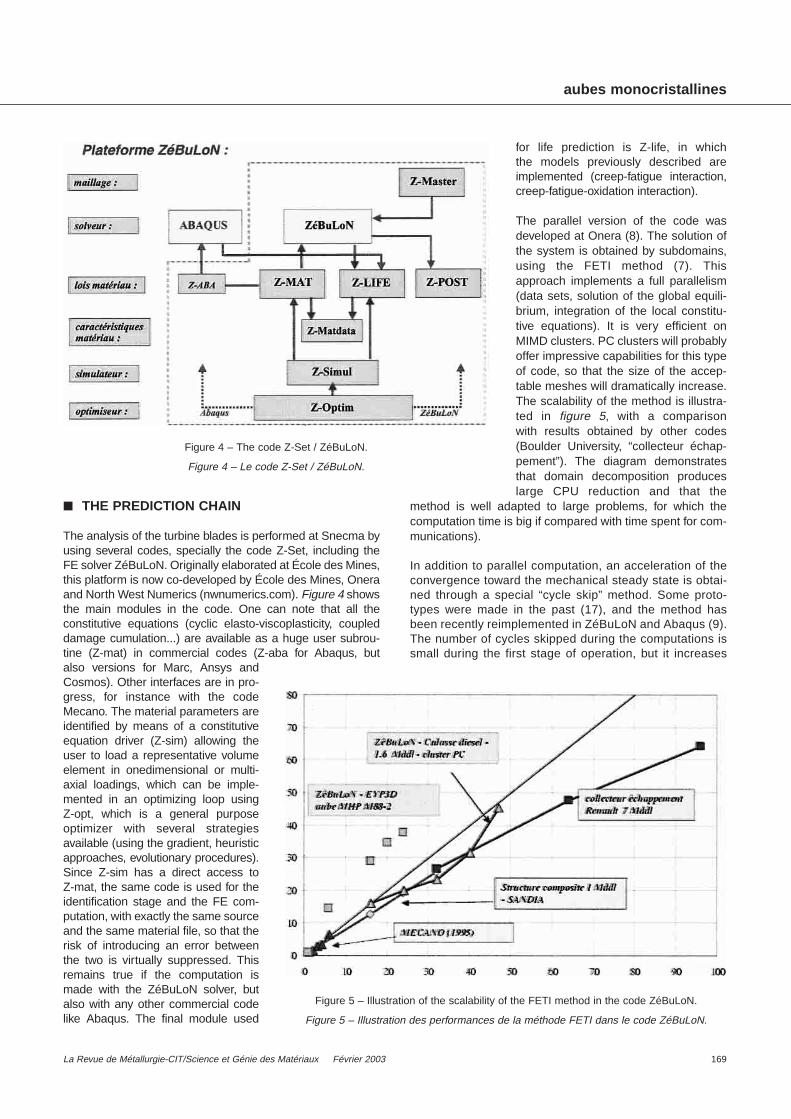
The parallel version of the code wasdeveloped at Onera (8). The solution ofthe system is obtained by subdomains,using the FETI method (7). Thisapproach implements a full parallelism(data sets, solution of the global equili-brium, integration of the local constitu-tive equations). It is very efficient onMIMD clusters. PC clusters will probablyoffer impressive capabilities for this typeof code, so that the size of the accep-table meshes will dramatically increase.The scalability of the method is illustra-ted in figure 5, with a comparison with results obtained by other codes(Boulder University, “collecteur échap-pement”). The diagram demonstratesthat domain decomposition produceslarge CPU reduction and that the
method is well adapted to large problems, for which thecomputation time is big if compared with time spent for com-munications).
In addition to parallel computation, an acceleration of theconvergence toward the mechanical steady state is obtai-ned through a special “cycle skip” method. Some proto-types were made in the past (17), and the method hasbeen recently reimplemented in ZéBuLoN and Abaqus (9).The number of cycles skipped during the computations issmall during the first stage of operation, but it increases
aubes monocristallines
La Revue de Métallurgie-CIT/Science et Génie des Matériaux Février 2003 169
Figure 4 – The code Z-Set / ZéBuLoN.
Figure 4 – Le code Z-Set / ZéBuLoN.
Figure 5 – Illustration of the scalability of the FETI method in the code ZéBuLoN.
Figure 5 – Illustration des performances de la méthode FETI dans le code ZéBuLoN.

gradually, and the method becomes speciallyefficient if a large number of cycles have to becomputed. Figure 6 demonstrates the goodagreement between a reference calculationwith all the cycles and the results obtained withthe “cycle skip” method.
■ RESULTS
Figure 7 shows a typical calculation, madesome years ago. A relatively coarse mesh isused, for representing the whole blade. Thistype of calculation allows to have an idea of thecritical areas. By the way, their location is nolonger intuitive, due to the large gradients inthe temperature field, and the 3D character ofthe stress field. The meshes presently usedhave a larger number of degrees of freedom,and a more precise geometrical description of the critical zones. The calculation must also take into account centrifugal forces, andaerodynamical forces. Their history is quitecomplex : in addition to take-off and landing, a series ofregime changes have generally to be considered, so thata realistic “cycle” is in fact made of a series of 50-100steps with 20-30 sub-cycles. The resulting stress histo-ries have to be treated for the application of the crack ini-tiation models. Rain flow is generally used to extract themost damaging events.
Modern blades are actively cooled. After introducing hol-low blades in the seventies, engineers have built more andmore complex systems. Nowadays, cool air, which is ledoff the compressor, is pumped through the blade and outthrough small holes on the leading edge and slits on thetrailing edge. Such a blade can now be computed (3),accounting for the presence of holes and slits in 3Delasto-viscoplastic finite element computations. This cal-culation was made possible only thanks to the parallelcomputation, since the number of dofs is larger than500,000. Even in that case, several days are necessary toachieve the computation. In order to get better CPU times,the presence of holes can also be accounted for by intro-ducing at the leading edge a zone of weakened materialas shown on figure 8a. This amounts to replacing the per-forated part of the blade by a homogeneous equivalentmedium. Its mechanical properties are obtained usinghomogenization methods. The unit cell consisting of asingle crystal small volume containing one hole can besubjected to complex loading conditions including tension,shear and hydrostatic pressure. An explicit effectiveconstitutive model is identified from the responses of thecell. Such a model of compressible single crystal plasticityhas been proposed in (3). It involves the plastic slip sys-tems and additional dilatant systems :
[5]
where the chosen expansion directions are n–
sdil = {100}.
The local stress-strain states around an underlying hole canthen be deduced from the overall stress and strain at a pointof the weakened zone, by means of standard concentrationmethods in homogenization theory (2). An example of sucha reconstructed stress field around a single hole is given infigure 8b. It can be shown that the use of an effective mate-rial law significantly improves this local prediction. Post-processing lifetime assessment models can the be used topredict the effect of the presence of holes and slit on crack
aubes monocristallines
170 La Revue de Métallurgie-CIT/Science et Génie des Matériaux Février 2003
Figure 6 – Comparison of the results given with or without the cycle skip technique.
Figure 6 – Comparaison des résultats obtenus avec ou sans la méthode de saut de cycles.
Figure 7 – Example of a temperature field on a typical turbine blade.
Figure 7 – Exemple d’un champ de température sur une aube de turbine typique.

initiation. The methodology is general enough to be exten-ded to other multiperforated jet engine components likecombustors and burners.
■ CONCLUDING REMARKS
The purpose of the paper was to make a brief review of theevolution of the design of turbine blades in the last thirtyyears. Major changes have to be mentioned. Single crystalsare now used for the hottest part of the engine, after classi-cal polycrystals then directionally solidified materials. Theshape of the blades is also more and more complex, withincurved leading edges and the presence of holes in orderto generate gaseous films to protect the material against thecombustion gas. New models have been developed accor-dingly and, since the power of the computers increasescontinuously, the strategy of the component lifeprediction isalso updated. In the industry, the design process needs agood cooperation between the various actors who have incharge combustion, fluid mechanics, thermal problems, andmechanics. Material engineering is also concerned, andexchanges with mechanical engineers are crucial. This typeof discussion is now traditional in France, and allows theengineers to have in hand mechanical models taking intoaccount the real microstructure of the materials.
A lifetime prediction is performed with the following steps :
– acquisition of the thermal fields and of the aeronauticalforces ;
– mesh of the whole blade ;
– FE computation of a series of typical missions, which mayuse parallel computers for large meshes ;
– evaluation of the time to crackinitiation with a post-processingwhich reads the stress and tem-perature history.
For critical cases, a structuralzoom can be performed, in orderto get a better representation ofcritical areas. This has to be madefor taking into account the rôle ofmultiple perforation.
Improvements in the methodo-logy are still to come. As a firstdirection for future researchauthors try to be able to predictshort crack propagation (andmaybe crack arrest) in singlecrystals, during multiaxial non-isothermal loadings. Thermal bar-riers are also an active researchfield. They involve a lot of coupledmechanisms. Understanding howthey operate, characterizing therate of damage in connection withdiffusion process, being ready to
give reliable predictions for spallation are still a challengefor researchers and engineers.
references
(1) Sidolo2.3, Manuel utilisateur (1996).
(2) BESSON (J.), CAILLETAUD (G.), CHABOCHE (J.-L.),FOREST (S.) – Mécanique non-linéaire des matériaux.Hermès (2001).
(3) CARDONA (J.-M.) – Comportement et durée de vie despièces multiperforées : application aux aubes de turbine. PhD thesis, École Nationale Supérieure des Mines de Paris(2000).
(4) CHABOCHE (J.-L.) – Calcul des déformations viscoplas-tiques d’une structure soumise à des gradients thermiquesévolutifs. PhD thesis, Univ. Orsay (1972).
(5) CHABOCHE (J.-L.), STOLTZ (C.) – Détermination desdurées de vie des aubes de turbine à gaz. Revue Françaisede Mécanique , 52 (1974), p. 37-47.
(6) ESPIÉ (L.) – Étude expérimentale et modélisation numériquedu comportement mécanique des superalliages. PhD thesis,ENSMP (1996).
(7) FAHRAT (C.), ROUX (F.-X.) – Implicit parallel processing in structural mechanics. Computational MechanicsAdvances , 2(1), (1994).
(8) FEYEL (F.), CAILLETAUD (G.), KRUCH (S.), ROUX (F.-X.) –Application du calcul parallèle aux modèles à grand nombrede variables internes. C.R. 3e Colloque National en calcul destructures, Giens, France (20-23 mai 1997), p. 309-314.
(9) FOERCH (R.), GROS (V.), MOUNOURY (V.), QUILICI (S.),CAILLETAUD (G.) – Cyclic calculations and life prediction inthermomechanical fatigue using the zmat library. In “Abaqususer metting”, Newport, USA (2000).
aubes monocristallines
La Revue de Métallurgie-CIT/Science et Génie des Matériaux Février 2003 171
Figure 8 – a) Part of a turbine blade with a zone in grey weakened by the presence of holesand modelled by a homogeneous substitution material ; b) equivalent stress field around a hole
reconstructed from the overall fields using homogenization techniques.
Figure 8 – Maillage d’une aube de turbine mettant en œuvre une zone de matériau homogèneéquivalent simulant la présence des trous de refroidissement ; b) reconstruction du champ local
à partir du calcul global uitlisant les techniques d’homogénéisation.
a) b)

(10) FOREST (S.), BARBE (F.), CAILLETAUD (G.) – Cosseratmodelling of size effects in the mechanical behaviour of poly-crystals and multiphase materials. Int. J. Solids Structures ,37 (2000), p. 7105-7126.
(11) FOREST (S.), PILVIN (P.) – Modelling the cyclic behaviour oftwo-phase single crystal nickel-based superalloys. Procee-dings of IUTAM Symposium on “Micromechanics of plasticityand damage of multiphase materials”, A. Pineau and A. Zaoui, eds, Kiuwer (1996), p. 51-58.
(12) GALLERNEAU (F.) – Étude et modélisation de l’endomma-gement d’un superalliage monocristallin revêtu pour aube deturbine. Doctorat d’Université, École Nationale Supérieuredes Mines de Paris (1995).
(13) HANRIOT (F.), CAILLETAUD (G.), RÉMY (L.) – Mechanicalbehaviour of a nickel-based superalloy single crystal. In “Hightemperature constitutive modelling - Theory and application”,A.D. Freed and K.P. Walker, eds, ASME (1991).
(14) LEMAITRE (J.), CHABOCHE (J.-L.) – Mechanics of solid mate-rials. Cambridge University Press, Cambridge, U.K. (1990).
(15) LESNE (P.-M.) – Amorçage et propagation de fissures sousgradients thermiques cycliques. PhD thesis, Université deLille (1985).
(16) MÉRIC (L.), POUBANNE (P.), CAILLETAUD (G.) – Singlecrystal modelling for structural calculations. Part I : Modelpresentation. J. of Engng. Mat. Technol. , 113 (1991),p. 162-170.
(17) SAVALLE (S.), CULIÉ (J.-P.) – Méthodes de calcul associéesaux lois de comportement cyclique et d’endommagement. La Recherche Aérospatiale , 5 (1978).
aubes monocristallines
172 La Revue de Métallurgie-CIT/Science et Génie des Matériaux Février 2003


![3D characterization and modelling of small fatigue cracks ...irsp2016.malab.com/wp-content/uploads/2016/07/AT13... · Small strain crystal plasticity [Meric and Cailletaud, 1991]](https://img.dokumen.tips/doc/110x75/5ec1f4b393e4a025a2723ab5/3d-characterization-and-modelling-of-small-fatigue-cracks-small-strain-crystal.jpg)