Embed Size (px)
Citation preview
ON QoS MULTICAST ROUTING PROTOCOLS
A THESIS SUBMITTED TO THE GRADUATE SCHOOL OF NATURAL AND APPLIED SCIENCES
OF MIDDLE EAST TECHNICAL UNIVERSITY
BY
ALPER BEREKETLİ
IN PARTIAL FULFILLMENT OF THE REQUIREMENTS FOR
THE DEGREE OF MASTER OF SCIENCE IN
ELECTRICAL AND ELECTRONICS ENGINEERING
SEPTEMBER 2005
Approval of the Graduate School of Natural and Applied Sciences
Prof. Dr. Canan Özgen
Director
I certify that this thesis satisfies all the requirements as a thesis for the degree of Master of Science.
Prof. Dr. İsmet Erkmen
Head of Department This is to certify that we have read this thesis and that in our opinion it is fully adequate, in scope and quality, as a thesis for the degree of Master of Science.
Asst. Prof. Dr. Cüneyt F. Bazlamaçcı Supervisor
Examining Committee Members Prof. Dr. Hasan Güran (METU, EE) Asst. Prof. Dr. Cüneyt F. Bazlamaçcı (METU, EE) Prof. Dr. Semih Bilgen (METU, EE) Asst. Prof. Dr. Özgür B. Akan (METU, EE) Dr. Altan Koçyiğit (METU, IS)

iii
I hereby declare that all information in this document has been obtained and presented in accordance with academic rules and ethical conduct. I also declare that, as required by these rules and conduct, I have fully cited and referenced all material and results that are not original to this work.
Alper BEREKETLİ

iv
ABSTRACT
ON QoS MULTICAST ROUTING PROTOCOLS
Bereketli, Alper
M.Sc., Department of Electrical and Electronics Engineering
Supervisor: Asst. Prof. Dr. Cüneyt F. Bazlamaçcı
September 2005, 101 pages
Multicasting is a technique used for distributing data packets from one or
more sources to a set of receivers on interconnected networks. Currently
developing network applications bring specific quality of service (QoS)
requirements like bounded delay, minimum bandwidth, and maximum data loss
rate. Providing the required quality of service addresses routing and resource
reservation concepts. In this study, a literature survey is carried out on traditional
and QoS multicast routing protocols, and the need for QoS routing protocols is
investigated. QoS multicast routing protocols are classified and compared
according to their multicast tree construction and resource reservation approaches.
Two QoS protocols, QROUTE and QMBF, are selected, and their performances
are experimentally compared using the network simulation tool Network
Simulator-2 (ns-2). The objective of the simulations is to compare the QoS
routing algorithms and their tree construction efficiencies. The first contribution

v
of the thesis is the survey and classification of traditional and QoS multicast
routing protocols. Another contribution is the ns-2 implementation of two QoS
multicast routing protocols. The final contribution of the thesis is the performance
evaluation of the recent protocols from a different perspective.
Keywords: Multicast, Quality of Service, Routing, Network Simulation,
Performance Evaluation

vi
ÖZ
HİZMET NİTELİĞİNE YÖNELİK ÇOĞA GÖNDERİM
YÖNLENDİRME PROTOKOLLERİ ÜZERİNE
Bereketli, Alper
Yüksek Lisans, Elektrik ve Elektronik Mühendisliği Bölümü
Tez Danışmanı: Yrd. Doç. Dr. Cüneyt F. Bazlamaçcı
Eylül 2005, 101 sayfa
Çoğa gönderim, arabağlantılı ağlarda veri paketlerinin bir veya daha fazla
kaynaktan bir alıcı grubuna dağıtılması için kullanılan bir tekniktir. Halen
gelişmekte olan ağ uygulamaları, sınırlı gecikme, asgari bant genişliği ve azami
veri kayıp oranı gibi belirli hizmet niteliği gereksinimleri getirmektedir. Gerek
duyulan hizmet niteliğini sağlamak, yönlendirme ve kaynak ayırma kavramlarına
işaret etmektedir. Bu çalışmada, geleneksel ve hizmet niteliğine yönelik çoğa
gönderim yönlendirme protokolleri üzerine literatür taraması gerçekleştirilmiş ve
hizmet niteliğine yönelik yönlendirme protokollerine olan ihtiyaç araştırılmıştır.
Hizmet niteliğine yönelik yönlendirme protokolleri, çoğa gönderim ağacı
oluşturulma ve kaynak ayırma yaklaşımlarına göre sınıflandırılmış ve
karşılaştırılmıştır. Hizmet niteliğine yönelik iki protokol, QROUTE ve QMBF,
seçilmiş ve başarımları deneysel olarak ağ benzetim aracı olan Network
vii
Simulator-2 (ns-2) kullanularak karşılaştırılmıştır. Benzetimlerin amacı, hizmet
niteliğine yönelik yönlendirme algoritmalarının ve ağaç oluşturma verimlerinin
karşılaştırılmasıdır. Tezin birinci katkısı, geleneksel ve hizmet niteliğine yönelik
çoğa gönderim yönlendirme protokollerinin incelenmesi ve karşılaştırılmasıdır.
Bir diğer katkı, hizmet niteliğine yönelik iki çoğa gönderim yönlendirme
protokolünün ns-2 üzerinde yaşama geçirilmesidir. Tezin son katkısı da yeni
protokollerin başarımının farklı bir bakış açısıyla değerlendirilmesidir.
Anahtar Kelimeler: Çoğa Gönderim, Hizmet Niteliği, Yönlendirme, Ağ
Benzetimi, Başarım Değerlendirmesi

viii
ACKNOWLEDGMENTS I would like to express my heartfelt thanks to my supervisor, Asst. Prof.
Dr. Cüneyt F. Bazlamaçcı, whose contributions greatly added to my graduate
experience, for his support, advice, and guidance during this study.
I owe my eternal gratitude my mother, Zişan Bereketli, and my father,
Mümtaz Bereketli, for the priceless support, patience, love and understanding they
provided me throughout my entire life.
A special thanks goes out to Coşkun Çelik for being such a good friend
and for sharing his graduate experiences with me.
I wish to express my appreciation to Ezgi Kadriye Yetkin, who has been a
source of inspiration and love all through this work.
Finally, I must acknowledge Asst. Prof. Dr. Özgür Barış Akan, whose
motivation and encouragement truly made a difference in my life.

ix
TABLE OF CONTENTS PLAGIARISM .......................................................................................................iii
ABSTRACT........................................................................................................... iv
ÖZ .......................................................................................................................... vi
ACKNOWLEDGMENTS....................................................................................viii
TABLE OF CONTENTS....................................................................................... ix
LIST OF TABLES ................................................................................................. xi
LIST OF FIGURES...............................................................................................xii
ABBREVIATIONS.............................................................................................. xiv
CHAPTER
1. INTRODUCTION............................................................................................... 1
2. INTERNET MULTICAST ROUTING .............................................................. 4
2.1 What is Multicast?............................................................................. 4
2.2 Introduction to the Internet Hierarchy and Addressing Scheme ....... 5
2.3 Internet Multicast Routing Protocols ................................................ 7
3. QoS MULTICAST ROUTING......................................................................... 18
3.1 Problem Description........................................................................ 18
3.2 Solution Approaches ....................................................................... 19
3.2.1 QGMRP........................................................................... 19
3.2.2 QoSMIC .......................................................................... 21
3.2.3 QMRP.............................................................................. 25
3.2.4 S-QMRP.......................................................................... 27
3.2.5 QROUTE......................................................................... 30
3.2.6 QMBF.............................................................................. 32
3.3 Protocol Classification and Comparison ......................................... 34

x
4. QROUTE AND QMBF..................................................................................... 43
4.1 QROUTE......................................................................................... 43
4.1.1 Description ...................................................................... 43
4.1.2 Simulations...................................................................... 55
4.1.3 Simulation Results........................................................... 57
4.2 QMBF.............................................................................................. 59
4.2.1 Description ...................................................................... 59
4.2.2 Simulations...................................................................... 68
4.2.3 Simulation Results........................................................... 68
5. SIMULATION WORK..................................................................................... 70
5.1 The Selected Protocols and The Simulation Environment.............. 70
5.2 QoS Performance Metrics ............................................................... 73
5.3 Experiments..................................................................................... 74
5.4 Simulation Results........................................................................... 76
6. CONCLUSION ................................................................................................. 91
REFERENCES...................................................................................................... 96

xi
LIST OF TABLES
Table 2.1 The Comparison of DVMRP, MOSPF, CBT and PIM......................... 17
Table 3.1 Description and Comparison of QoS Multicast Routing Protocols ...... 39
Table 4.1 Summary of control packets in QROUTE ............................................ 44
Table 4.2 Summary of control packets in QMBF ................................................. 60

xii
LIST OF FIGURES Figure 2.1 Illustration of (a) unicast, (b) multicast, and (c) broadcast .................... 4
Figure 2.2 IPv4 addresses........................................................................................ 6
Figure 2.3 Shortest path trees and shared trees ....................................................... 9
Figure 2.4 The basic concept of the DVMRP operations ..................................... 10
Figure 2.5 A sample MOSPF configuration.......................................................... 12
Figure 2.6 The operations of the MOSPF ............................................................. 13
Figure 2.7 The CBT when there are some join requests ....................................... 14
Figure 2.8 The operations of the CBT protocols when a host sends a datagram .. 15
Figure 3.1 Local and Multicast Tree Search Processes in QoSMIC..................... 23
Figure 3.2 ACK follows the path of its REQUEST .............................................. 26
Figure 3.3 An illustration of Bounded Flooding technique .................................. 34
Figure 4.1 The basic operations of QROUTE....................................................... 45
Figure 4.2 Causes of loops and loop avoidance in QROUTE............................... 49
Figure 4.3 QROUTE: When a host wants to join ................................................. 51
Figure 4.4 QROUTE: When a host wants to leave ............................................... 51
Figure 4.5 QROUTE: When a router receives REQUEST.................................... 52
Figure 4.6 QROUTE: When a router receives CONFIRM ................................... 53
Figure 4.7 QROUTE: When a router receives PRUNE-BACK............................. 54
Figure 4.8 QROUTE: When a router receives PRUNE-BRANCH ....................... 55
Figure 4.9 QMBF: When a router receives JOIN ................................................. 65
Figure 4.10 QMBF: When a router receives CONFIRM ...................................... 66
Figure 4.11 QMBF: When a router receives UNACK........................................... 67
xiii
Figure 5.1 Sample 50-node BRITE topology with a minimum degree of one ..... 72
Figure 5.2 Sample 50-node BRITE topology with a minimum degree of two ..... 72
Figure 5.3 Sample 100-node BRITE topology with a minimum degree of two ... 73
Figure 5.4 Total overhead vs. Group size (50-Nodes, tight bounds) .................... 78
Figure 5.5 Total overhead vs. Group size (50-Nodes, loose bounds) ................... 78
Figure 5.6 Total overhead vs. Group size (100-Nodes, tight bounds) .................. 79
Figure 5.7 Total overhead vs. Group size (100-Nodes, loose bounds) ................. 79
Figure 5.8 Average overhead vs. Group size (50-Nodes, tight bounds) ............... 80
Figure 5.9 Average overhead vs. Group size (50-Nodes, loose bounds) .............. 80
Figure 5.10 Average overhead vs. Group size (100-Nodes, tight bounds) ........... 81
Figure 5.11 Average overhead vs. Group size (100-Nodes, loose bounds) .......... 81
Figure 5.12 Success ratio vs. Group size (50-Nodes, tight bounds) ..................... 82
Figure 5.13 Success ratio vs. Group size (50-Nodes, loose bounds) .................... 82
Figure 5.14 Success ratio vs. Group size (100-Nodes, tight bounds) ................... 83
Figure 5.15 Success ratio vs. Group size (100-Nodes, loose bounds) .................. 83
Figure 5.16 Total setup latency vs. Group size (50-Nodes, tight bounds) ............ 86
Figure 5.17 Total setup latency vs. Group size (50-Nodes, loose bounds)........... 86
Figure 5.18 Total setup latency vs. Group size (100-Nodes, tight bounds) .......... 87
Figure 5.19 Total setup latency vs. Group size (100-Nodes, loose bounds)......... 87
Figure 5.20 Average setup latency vs. Group size (50-Nodes, tight bounds)....... 88
Figure 5.21 Average setup latency vs. Group size (50-Nodes, loose bounds)...... 88
Figure 5.22 Average setup latency vs. Group size (100-Nodes, tight bounds)..... 89
Figure 5.23 Average setup latency vs. Group size (100-Nodes, loose bounds).... 89

xiv
ABBREVIATIONS ACK: Acknowledgment
aQoS: Accumulated QoS Parameters
BGMP: Border Gateway Multicast Protocol
BID_ORDER: Bidding Order Message
BID_REQ: Bidding Request Message
BRITE: Boston University Representative Internet Topology Generator
CBT: Core-based Tree
CIDR: Classless Interdomain Routing
DiffServ: Differentiated Services
DVMRP: Distance Vector Multicast Routing Protocol
EW: Early Warning
EXPRESS: Explicitly Requested Single Source
FR: Fork Routing
IGMP: Internet Group Management Protocol
IntServ: Integrated Services
ISP: Internet Service Provider
LNC: Local Network Cell
LSA: Link State Advertisement
MASC: Multicast Address-Set Claim
MBD: Maximum Branching Degree
MBGP: Multicast Border Gateway Protocol
MBL: Maximum Branching Level
MBone: Multicast Backbone
MFT: Multicast Forwarding Table
MOSPF: Multicast Open Shortest Path First
mQoS: Total QoS Metrics
MSDP: Multicast Source Discovery Protocol

xv
NACK: Negative Acknowledgment
NAP: Network Access Point
ns-2: Network Simulator-2
NSP: Network Service Provider
OMNET: Objective Modular Network Testbed
OSPF: Open Shortest Path First
PFB: Partial Feasible Branch
PIM: Protocol-independent Multicast
PIM-DM: Protocol-independent Multicast Dense Mode
PIM-SM: Protocol-independent Multicast Sparse Mode
QGMRP: QoS-guaranteed Multicast Routing Protocol
QMBF: QoS-aware Multicast Routing with Bounded Flooding
QMRP: QoS-aware Multicast Routing Protocol
QoS: Quality of Service
QoSB: Bandwidth Requirement for QoS
QoSD: Delay Requirement for QoS
QoSMIC: QoS-sensitive Multicast Internet Protocol
QROUTE: QoS-guaranteed Multicast Routing
RGMP: Receiver-initiated Group Membership Protocol
RJCT: Reject
RNP: Regional Network Provider
RP: Rendezvous Point
RPF: Reverse Path Forwarding
RPLY: Reply
rQoS: Required QoS
RQST: Request
RSVP: Resource Reservation Protocol
SM: Simple Multicast
SoMR: Scalable QoS Multicast Routing
SPR: Shortest (Single) Path Routing
SSF: Scalable Simulation Framework

xvi
TCP: Transport Control Protocol
TTL: Time to Live
UNACK: Negative Acknowledgment
UR: Unicast Routing
YAM: Yet Another Multicast
1
CHAPTER 1
INTRODUCTION
Multicasting is a technique proposed to distribute datagrams to a set of
interested receivers on interconnected networks. The growing Internet has brought
many new and challenging network applications such as teleconferencing,
interactive gaming, distance learning, Internet telephony, real-time multimedia
playing, distributed computing, and distributed database applications. The
common point of these applications is that all involve interactions among multiple
users forming a group. In contrast to the traditional one-to-one communication
(unicast), these applications may be costly and infeasible to implement unless
some underlying network protocols are designed.
The need for the multicast applications brings a need for efficient data
transfer between many users belonging to the same multicast communication
group. The data to be carried between end hosts must follow the most efficient
path and it must be delivered to the correct set of users; that is, data must be
routed correctly and efficiently. Some routing protocols are proposed to meet
these conditions.
Traditional multicast routing protocols consider only best-effort traffic.
The development of high-speed networks opens a new research field, which is to
provide quality of service (QoS) for multicast applications. Timely and
satisfactory information delivery over a decentralized and shared network is
challenging and complicated. A network that is originally designed for best-effort
traffic such as the Internet makes things even worse. To ensure the quality of data
delivery in terms of delay, capacity, or loss, some kind of network resource
reservation is required. Although a resource reservation protocol addresses the

2
problem of reserving resources on a multicast tree, a routing protocol is necessary
to construct a feasible multicast tree that covers all multicast group members and
provides the required resources.
There is now an extensive literature on the design of QoS multicast routing
protocols. In this study, different classifications of QoS multicast routing
protocols are examined and two of them are selected for comparative performance
evaluation. The main differences between the proposed QoS multicast routing
protocols are in their tree construction approaches and resource reservation
awareness.
The two protocols compared in the performance evaluation study are
QROUTE and QMBF. The reasoning behind the selection of these two protocols
is based on the facts that these protocols are more recent than the other
investigated protocols, they have never been compared with each other, and they
are classified as QoS-guaranteed protocols due to their resource reservation
intelligence.
In the simulations, some performance metrics, namely packet overhead,
success ratio, and latency, are compared with varying number of multicast group
members under different network conditions and QoS requirements.
There are three main contributions of this study. Firstly, this study
includes a detailed survey and a classification of traditional multicast routing
methods and state-of-the-art QoS multicast routing protocols. Secondly, two
recently developed QoS multicast routing protocols are implemented in the
network simulator ns-2. Although ns-2 is a widely used network simulator, there
are hardly any publicly available QoS multicast routing protocol implementations
in ns-2. Finally, the performance evaluation of the two selected QoS multicast
routing protocols is carried out to gain insight into their operation.
The organization of the thesis is as follows:
Chapter 2 presents the fundamentals of multicast. Multicast
communication is described and traditional multicast routing protocols are
compared.
3
Chapter 3 investigates the QoS routing problem and describes some
solution approaches. QoS multicast routing protocols are classified and details of
representative protocols for each class are given. A summary comparison table is
developed.
Chapter 4 concentrates on the two selected QoS multicast routing
protocols. Main ideas, multicast tree construction approaches, and resource
reservation approaches of QROUTE and QMBF are explained in detail. The
operations of the protocols are described and flowcharts representing the details of
the operations are constructed for ease of understanding and for simulations. The
past analysis carried out on the two protocols in related works is also studied and
reviewed in detail in this chapter.
Chapter 5 explains the simulation environment and QoS metrics used in
this study, and gives the details of the experiments. The results of our simulations
and comments on the results are also presented in this chapter.
Chapter 6 concludes the thesis with a summary of the performed study,
with comments on the performance evaluation analysis, and some possible future
research directions.

4
CHAPTER 2
INTERNET MULTICAST ROUTING
2.1 What is Multicast?
Multicasting refers to sending datagrams from a source to a subset of
destinations in a network. In multicast, the sender needs to send every datagram
only once and there can be at most one copy of the datagram on a physical link.
Compared with broadcast, only the related routers and hosts take part in the
transmission and reception of multicast datagrams. The concept is illustrated in
Figure 2.1.
Figure 2.1 Illustration of (a) unicast, (b) multicast, and (c) broadcast
Suppose we want to send a message from the source S to the receivers R1
and R2. In unicast case, a copy of the message would be sent to the receivers

5
separately and duplicate copies will appear on some links. In multicast, after the
sender makes a single transmission, each intermediate node copies the message
and sends, as required, to outgoing links. Finally, broadcast requires that copies
are made and sent to each outgoing link at each intermediate node. As a result,
even irrelevant nodes that do not require a copy, such as R3 in Figure 2.1, will get
the message.
Nowadays, many emerging Internet applications such as video/audio
conferencing, web cache updating, file distribution, distance learning, and gaming
require multipoint delivery. Hence, efficient and scalable point/multipoint to
multipoint data delivery is crucial to the development of the Internet.
2.2 Introduction to the Internet Hierarchy and Addressing Scheme
The Internet has a hierarchical structure. The center of the hierarchy is
made up of primary Network Service Providers (NSPs) that are interconnected by
high-speed links and provide Internet access to national Internet Service Providers
(ISPs) and Regional Network Providers (RNPs) through Network Access Points
(NAPs). Primary NSPs, the high-speed links between them and NAPs together
form the Internet backbone. Local ISPs connect to Internet through national ISPs,
RNPs, or at NAPs to an NSP and provide Internet service to their customers.
In the Internet, IP address blocks are allocated to ISPs. An ISP divides its
allocated block among its customers. Hosts which share a common part of an IP
address are said to be in the same domain. There are four classes of IP addresses,
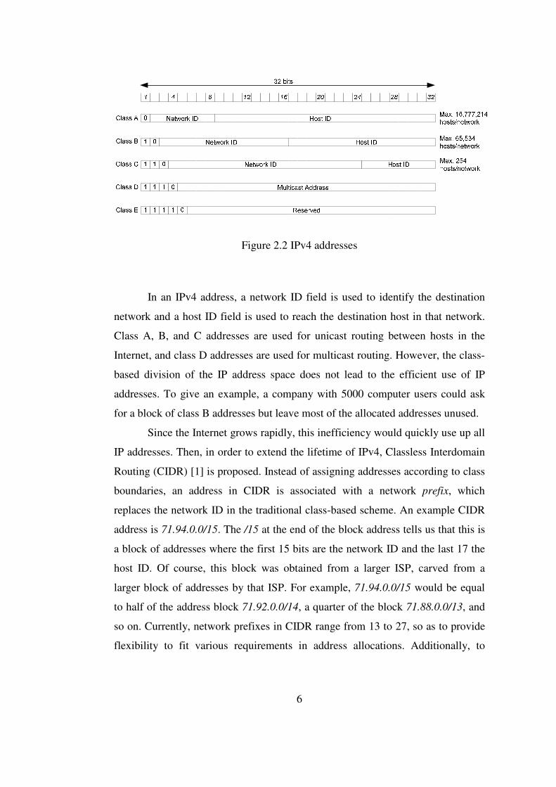
as shown in Figure 2.2.
6
Figure 2.2 IPv4 addresses
In an IPv4 address, a network ID field is used to identify the destination
network and a host ID field is used to reach the destination host in that network.
Class A, B, and C addresses are used for unicast routing between hosts in the
Internet, and class D addresses are used for multicast routing. However, the class-
based division of the IP address space does not lead to the efficient use of IP
addresses. To give an example, a company with 5000 computer users could ask
for a block of class B addresses but leave most of the allocated addresses unused.
Since the Internet grows rapidly, this inefficiency would quickly use up all
IP addresses. Then, in order to extend the lifetime of IPv4, Classless Interdomain
Routing (CIDR) [1] is proposed. Instead of assigning addresses according to class
boundaries, an address in CIDR is associated with a network prefix, which
replaces the network ID in the traditional class-based scheme. An example CIDR
address is 71.94.0.0/15. The /15 at the end of the block address tells us that this is
a block of addresses where the first 15 bits are the network ID and the last 17 the
host ID. Of course, this block was obtained from a larger ISP, carved from a
larger block of addresses by that ISP. For example, 71.94.0.0/15 would be equal
to half of the address block 71.92.0.0/14, a quarter of the block 71.88.0.0/13, and
so on. Currently, network prefixes in CIDR range from 13 to 27, so as to provide
flexibility to fit various requirements in address allocations. Additionally, to

7
reduce routing table size and to decrease routing time at routers, CIDR enables
route aggregation i.e., a number of low-level routes can be represented by a single
high-level routing entry.
2.3 Internet Multicast Routing Protocols
The first Internet multicast pattern, the host group model [2], was
proposed in the late 1980s, and, since the beginning of 1990s, Internet multicast
has been tested and implemented on the Multicast Backbone (MBone) [3].
However, multicast has not been fully developed yet, and there are issues open for
further investigation, such as scalable multicast routing, reliable multicast and
multicast flow and congestion control.
The host group model was proposed in 1989 [2]. In this model, a single
class-D IP address represents a group of hosts participating in the same multicast
session. A host may join or leave its group at any time, it may belong to more than
one group at a time, and to send a datagram to a group, it neither needs to know
the membership state of the group nor has to be a member of that group. Data
delivery in this model is best effort; that is, multicast routers have the
responsibility of delivering the multicast datagrams. Senders multicast to their
local links, and receivers receive from their local links.
The current Internet multicast architecture, which can be said to be largely
originated from the host group model, consists of group management protocols,
routing protocols, and transport protocols. The group management protocols for
hosts are used to report their group membership state information to the multicast
routers on the subnet. In Internet multicast, Internet Group Management Protocol
(IGMP) [2,4,5] is used as the group management protocol currently; nevertheless,
new protocols are still coming out, such as the Receiver-initiated Group
Membership Protocol (RGMP) [6].
Many multicast applications have requirements beyond the best effort
delivery provided by multicast routing protocols. Therefore, various multicast
transport protocols are proposed on top of the multicast routing protocols to meet

8
the needs of different applications. In [21], they are classified according to the
kind of applications they support.
Multicast routing protocols on the Internet aim to solve the problem of
efficient multicast datagram transmission between subnetworks. A natural
structure considered in multicast routing is a tree [16]. The suggested multicast
routing protocols differ in the construction of the multicast trees. There are mainly
two kinds of multicast trees in consideration: source-based shortest path tree and
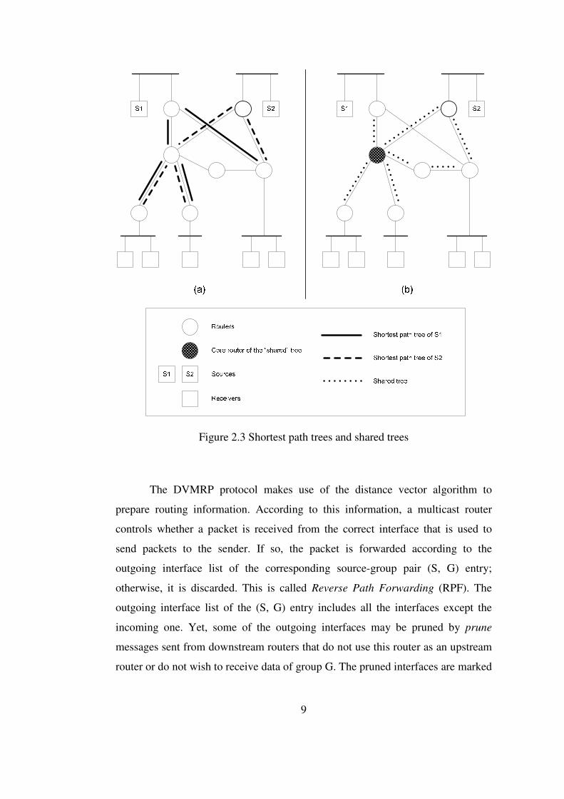
shared tree, as illustrated in Figure 2.3 [16].
In Figure 2.3-a, two sources, S1 and S2, use the shortest paths to reach
their host subnets. But, in Figure 2.3-b, the sources send their data first to the core
of their shared tree. The common core then distributes the data packets to their
destinations. As source-based trees use the shortest path for minimum delay, these
structures are appropriate for regions where group members are densely
distributed. On the other hand, shared trees have better resource utilization than
source based trees, while increasing the traffic concentration.
The root of a shared tree is the core router. Distance Vector Multicast
Routing Protocol (DVMRP) [7], Protocol-independent Multicast Dense Mode
(PIM-DM) [8], and Multicast Open Shortest Path First (MOSPF) [9] use
shortest path trees, while Protocol-independent Multicast Sparse Mode PIM-SM
[10], Core-based Tree (CBT) [11,12], and Border Gateway Multicast Protocol
(BGMP) [13] use shared trees. Moreover, a shared tree in PIM-SM can be
switched to a shortest path tree when needed.
The trees formed by multicast routing protocols are reflected on the
Multicast Forwarding Tables (MFTs) in the in-tree routers. A common MFT
contains a set of outgoing –and possibly incoming– interfaces for each indexed
group ID. If a multicast data packet matches a group ID index of the MFT, and if
it comes from the correct incoming interface (protocols using bidirectional trees,
such as CBT and BGMP do not perform this checking), the packet is forwarded to
all interfaces in the outgoing interfaces list of this MFT entry; otherwise, the
packet will be discarded.
9
Figure 2.3 Shortest path trees and shared trees
The DVMRP protocol makes use of the distance vector algorithm to
prepare routing information. According to this information, a multicast router
controls whether a packet is received from the correct interface that is used to
send packets to the sender. If so, the packet is forwarded according to the
outgoing interface list of the corresponding source-group pair (S, G) entry;
otherwise, it is discarded. This is called Reverse Path Forwarding (RPF). The
outgoing interface list of the (S, G) entry includes all the interfaces except the
incoming one. Yet, some of the outgoing interfaces may be pruned by prune
messages sent from downstream routers that do not use this router as an upstream
router or do not wish to receive data of group G. The pruned interfaces are marked
10
and will be restored after a certain time-out period; so, downstream routers have
to send prune messages periodically to maintain an interface pruned. This is
called flood and prune [7].
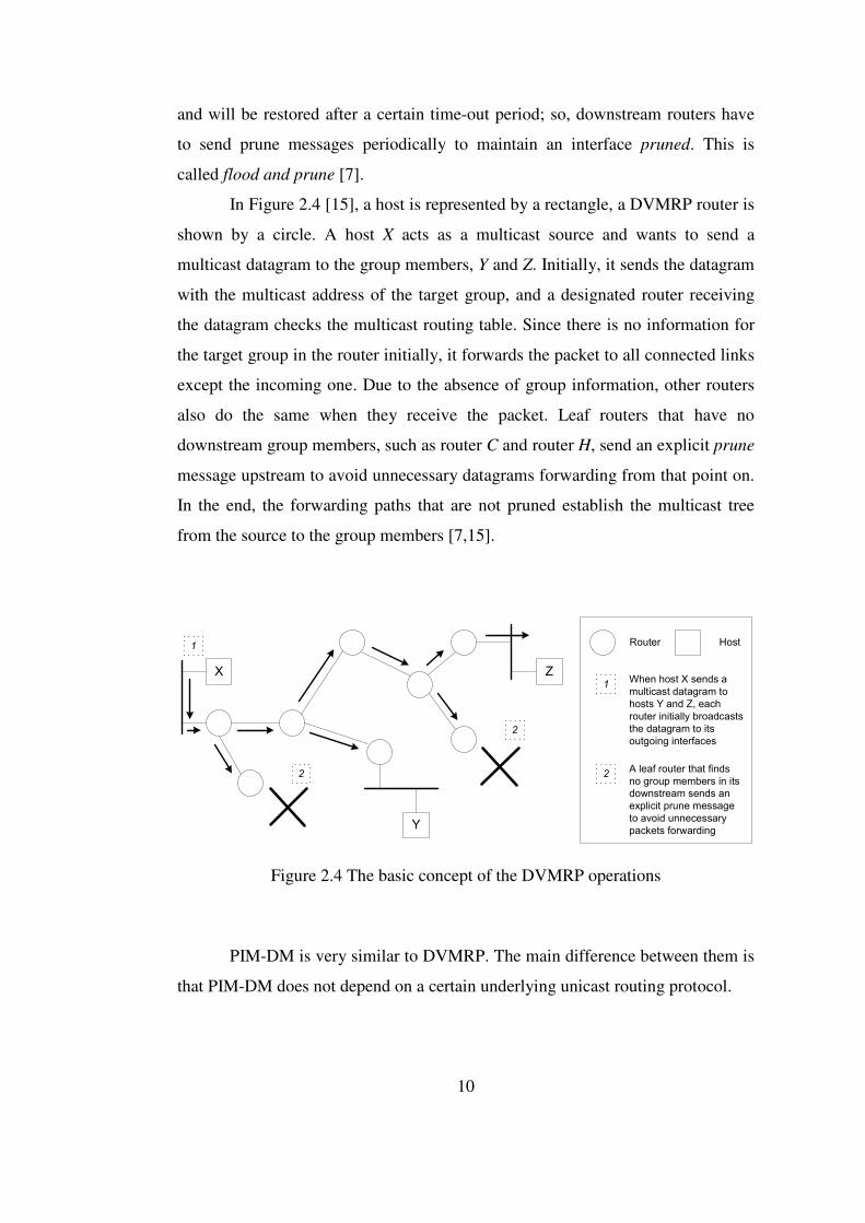
In Figure 2.4 [15], a host is represented by a rectangle, a DVMRP router is
shown by a circle. A host X acts as a multicast source and wants to send a
multicast datagram to the group members, Y and Z. Initially, it sends the datagram
with the multicast address of the target group, and a designated router receiving
the datagram checks the multicast routing table. Since there is no information for
the target group in the router initially, it forwards the packet to all connected links
except the incoming one. Due to the absence of group information, other routers
also do the same when they receive the packet. Leaf routers that have no
downstream group members, such as router C and router H, send an explicit prune
message upstream to avoid unnecessary datagrams forwarding from that point on.
In the end, the forwarding paths that are not pruned establish the multicast tree
from the source to the group members [7,15].
X Z
Y
1
2
1
2
2
Router Host
When host X sends a
multicast datagram to
hosts Y and Z, each
router initially broadcasts
the datagram to its
outgoing interfaces
A leaf router that finds
no group members in its
downstream sends an
explicit prune message
to avoid unnecessary
packets forwarding
Figure 2.4 The basic concept of the DVMRP operations
PIM-DM is very similar to DVMRP. The main difference between them is
that PIM-DM does not depend on a certain underlying unicast routing protocol.
11
The MOSPF protocol can be thought as the multicast version of the link-
state routing protocol OSPF version 2 [14]. Each router has the whole network
and membership information by flooding a Link State Advertisement (LSA),
called group membership LSA. Routers advertise their local state information to
the network periodically, and each router collects this information in a link-state
database. Upon the arrival of the first data packet for a group, each router builds
the shortest path tree rooted at the sender of the datagram and maintains this tree
construction knowledge for future usage [9,15]. Figure 2.5 and Figure 2.6 [15]
illustrate MOSPF.

12
R1
R4
R3R2H2, A
H3, B
H7
H5H4, B
H9, A
H8
H6
H1, B
R5
N3
N6
R
H
NRouter Network
Host that does not belong to
a multicast group
N5
N4
N2
N1
Hi, kHost i that is a member of
multicast group k
3
3 11
2
8
1 10
1
4
1
From
To
R1
R4
R3
R2
. . .
. . .
. . .
. . .
. . .
. . .
. . .. . .. . .. . .. . .
N3N2N1Group
Membership
1
None
B
A, B
B
1
3
1
1
3
Database of router R5
Figure 2.5 A sample MOSPF configuration
13
R1
R4
R3R2H2, A
H3, B
H7
H5H4, B
H9, A
H8
H6
H1, B
R5
N3
N6
N5
N4
N2
N1
3
3 11
2
8
1 10
1
4
1
When H6 wants to send a multicast
datagram to group A, R3 uses a
Dijkstra-like shortest path algorithm to
build a multicast delivery tree
The datagram is forwarded to the group
members along the branches of the
constructed multicast delivery tree
1 2
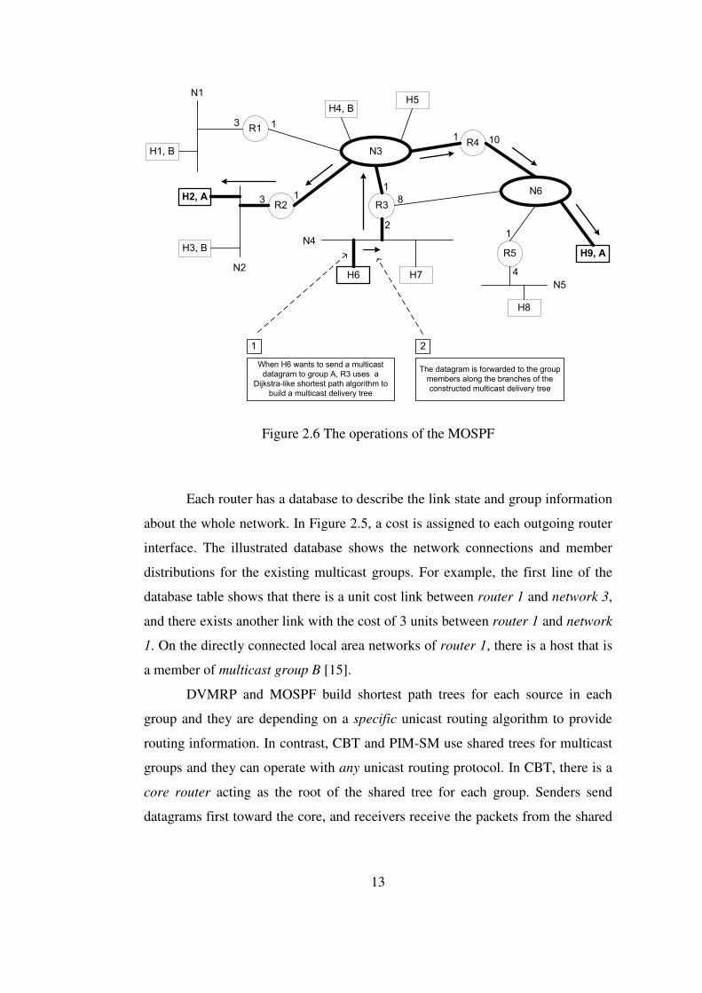
Figure 2.6 The operations of the MOSPF Each router has a database to describe the link state and group information
about the whole network. In Figure 2.5, a cost is assigned to each outgoing router
interface. The illustrated database shows the network connections and member
distributions for the existing multicast groups. For example, the first line of the
database table shows that there is a unit cost link between router 1 and network 3,
and there exists another link with the cost of 3 units between router 1 and network
1. On the directly connected local area networks of router 1, there is a host that is
a member of multicast group B [15].
DVMRP and MOSPF build shortest path trees for each source in each
group and they are depending on a specific unicast routing algorithm to provide
routing information. In contrast, CBT and PIM-SM use shared trees for multicast
groups and they can operate with any unicast routing protocol. In CBT, there is a
core router acting as the root of the shared tree for each group. Senders send
datagrams first toward the core, and receivers receive the packets from the shared

14
tree. PIM-SM works in a similar way, but the core router is now called the
Rendezvous Point (RP) [10,15].
When there are no members in the CBT system, the core router discards
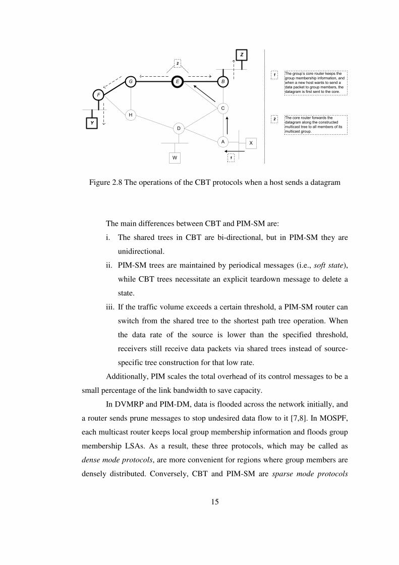
incoming data packets, since it has no group information [11,12]. Figure 2.7 [15]
shows the situation when some join requests exist in the system. In that case, host
Y and host Z want to join group S. Host Y sends an IGMP membership report
indicating its request to receive traffic relevant to the group S. The next-hop router
receiving this IGMP report sends a Join-Request message to the core router E.
The next-hop routers for other hosts may try to build such a path towards the core,
too. Finally, a multicast delivery tree rooted at the core is constructed to cover all
members. From that point on, when hosts join the multicast group, the core router
of the group keeps the group membership information. When a host tries to send a
datagram to the multicast group, the datagram is again sent to core router, and the
core router forwards the datagram along the constructed multicast delivery tree to
all group members. Figure 2.8 [15] shows this scenario.
F
B
C
E
A
D
H
G
Y
Z
X
W
1
2
3
1 There are no multicast group
members in the system, and node E
is chosen as the “core” router
manually.
2 Host Y sends an IGMP membership
report to announce that it wishes to
receive traffic addressed to the
multicast group with the core E.
Upon receipt of this IGMP report,
router F will issue a join request
message to the group’s core router
E. This request message travels a
specific path along the way towards
the core.
3 Host Z tries the same thing as host
Y and sends a join request to the
core for building a specific path. At
the end, a multicast delivery tree
rooted at the core is formed (shown
with the bold lines).
Figure 2.7 The CBT when there are some join requests
15
F
B
C
E
A
D
H
G
Y
Z
X
W 1
2
1 The group’s core router keeps the
group membership information, and
when a new host wants to send a
data packet to group members, the
datagram is first sent to the core.
2 The core router forwards the
datagram along the constructed
multicast tree to all members of its
multicast group.
Figure 2.8 The operations of the CBT protocols when a host sends a datagram
The main differences between CBT and PIM-SM are:
i. The shared trees in CBT are bi-directional, but in PIM-SM they are
unidirectional.
ii. PIM-SM trees are maintained by periodical messages (i.e., soft state),
while CBT trees necessitate an explicit teardown message to delete a
state.
iii. If the traffic volume exceeds a certain threshold, a PIM-SM router can
switch from the shared tree to the shortest path tree operation. When
the data rate of the source is lower than the specified threshold,
receivers still receive data packets via shared trees instead of source-
specific tree construction for that low rate.
Additionally, PIM scales the total overhead of its control messages to be a
small percentage of the link bandwidth to save capacity.
In DVMRP and PIM-DM, data is flooded across the network initially, and
a router sends prune messages to stop undesired data flow to it [7,8]. In MOSPF,
each multicast router keeps local group membership information and floods group
membership LSAs. As a result, these three protocols, which may be called as
dense mode protocols, are more convenient for regions where group members are
densely distributed. Conversely, CBT and PIM-SM are sparse mode protocols
16
designed for regions where group members are thinly scattered. In this case, only
multicast routers with local group members or routers required for transmission
can join the shared tree, and all other routers stay unaware of the group.
Therefore, CBT and PIM-SM have better scalability than the dense mode
protocols. However, CBT and PIM-SM need to flood the core/RP information to
all multicast routers to be used when sending datagrams or joining a multicast
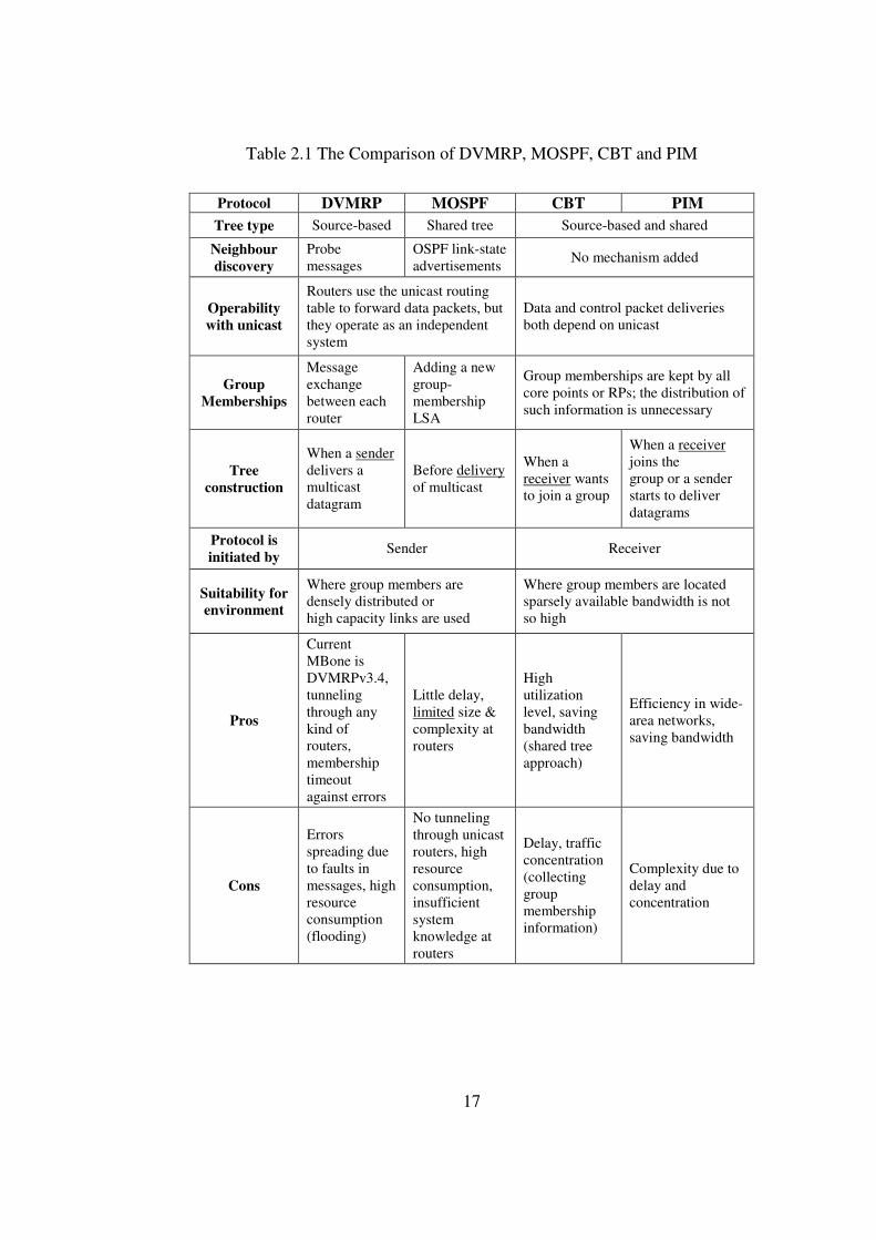
group [10,12]. These basic multicast routing protocols are compared in [15,16],
and a comparison table is already presented in [15]. This table is enhanced in this
work as illustrated in Table 2.1.
For the reasons stated above, these protocols cannot be used directly for
Internet wide interdomain multicast. For interdomain multicast, some solutions
are proposed. One of them is the Multicast BGP (MBGP)/PIM-SM/Multicast
Source Discovery Protocol (MSDP) scheme, which is easy to implement, but
lacks scalability [17,18]. Other works include the BGMP - Multicast Address-Set
Claim (MASC) solution, Simple Multicast (SM) [19], Explicitly Requested Single
Source (EXPRESS) multicast [20], etc.
17
Table 2.1 The Comparison of DVMRP, MOSPF, CBT and PIM
Protocol DVMRP MOSPF CBT PIM Tree type Source-based Shared tree Source-based and shared
Neighbour discovery
Probe messages
OSPF link-state advertisements No mechanism added
Operability with unicast
Routers use the unicast routing table to forward data packets, but they operate as an independent system
Data and control packet deliveries both depend on unicast
Group Memberships
Message exchange between each router
Adding a new group-membership LSA
Group memberships are kept by all core points or RPs; the distribution of such information is unnecessary
Tree construction
When a sender delivers a multicast datagram
Before delivery of multicast
When a receiver wants to join a group
When a receiver joins the group or a sender starts to deliver datagrams
Protocol is initiated by
Sender Receiver
Suitability for environment
Where group members are densely distributed or high capacity links are used
Where group members are located sparsely available bandwidth is not so high
Pros
Current MBone is DVMRPv3.4, tunneling through any kind of routers, membership timeout against errors
Little delay, limited size & complexity at routers
High utilization level, saving bandwidth (shared tree approach)
Efficiency in wide-area networks, saving bandwidth
Cons
Errors spreading due to faults in messages, high resource consumption (flooding)
No tunneling through unicast routers, high resource consumption, insufficient system knowledge at routers
Delay, traffic concentration (collecting group membership information)
Complexity due to delay and concentration
18
CHAPTER 3
QoS MULTICAST ROUTING
3.1 Problem Description
Multicast technology aims at the need of communication among a group
of users, and the continuous growth of Internet applications demanding multicast
communications has resulted in the proposal of many multicast protocols. As far
as basic principles are concerned, unicast is sufficient for the communication
requirements on the Internet, but the goal is to do the work with minimum cost
and maximum efficiency [22]. Some of the most common design constraints are
maximum scalability, minimal overhead, redundant forwarding avoidance,
address conflict elimination, and compatibility with existing protocols.
Together with the concept of high-performance networking, multicast
routing with quality of service (QoS) constraints has become a very important
research issue. In addition to the common and ordinary multicast routing
algorithm design goals stated in proposed protocols [7-14,19,20,22], a QoS
multicast routing protocol discusses the multicast routing problem with one or
more of the QoS constraints such as delay, jitter, bandwidth and packet loss.
Recently, there has been a lot of interest in services requiring certain QoS
from networks, such as multimedia services providing audio and video traffic.
Contrary to these QoS requirements, traditional protocols provide best-effort data
traffic and construct multicast trees based on connectivity. The trees they establish
may be unsatisfactory when QoS is considered because of the lack of resources
[23-25]. As the importance of QoS has become understood more clearly, more
complex QoS architectures (e.g., IntServ [27], DiffServ [26]) have been
developed, since the Internet provides best-effort service and does not guarantee
19
any QoS. These architectures try to meet high service requirements but do not
include QoS-aware routing mechanisms yet. Most of the QoS routing research
focuses on unicast traffic [27,28], and multicast routing is intended to be a
mechanism for many-to-many communications in the Internet with the core
function of creating a multicast distribution tree. Not all of the multicast routing
protocols under development are QoS-aware; they usually construct shortest path
trees rooted at a single router. The multicast trees can also be shared; packets
from all the sources travel along the same distribution tree.
The following sections, 3.2 and 3.3, are going to present and compare
some basic Internet QoS multicast routing protocols. The protocols are described
and compared according to how they differ in satisfying user requests.
3.2 Solution Approaches
In this section, six fundamental QoS Internet multicast routing protocols,
namely QGMRP, QoSMIC, QMRP, S-QMRP, QROUTE, and QMBF are
described. These protocols are chosen as regards their efficiency, QoS support,
and how frequently they are referenced.
3.2.1 QGMRP
The main ideas in the proposed QoS multicast routing algorithms are cost
optimization, delay optimization, minimizing a given selection function for a
minimum spanning tree, or using an extra global control element for multicast
routing tree construction [26,29-31]. These design concepts bring the drawbacks
of computation overhead, global network information dependence, and failure in
handling dynamic membership issues efficiently. Moreover, it is usually difficult
to extend these ideas to support multiple QoS constraints; and therefore most
protocols generally control only delay (and possibly bandwidth) as a QoS metric.
QGMRP (QoS Guaranteed Multicast Routing Protocol) [32] constructs a
multicast tree that optimizes end-to-end delay, inter-receiver jitter, available

20
bandwidth, and packet loss probability. QGMRP can operate on any underlying
unicast routing protocol, reduce tree construction overhead, and support dynamic
membership.
QGMRP has a distributed algorithm working in either unicast routing
(UR) or fork routing (FR) modes [32]. The former fits the case in which each
node or link has enough resources to guarantee the desired QoS requirement. The
latter searches for multiple feasible paths, and selects an optimal or a near-optimal
path for connecting a new member to the existing multicast group. The path
searching process changes between UR and FR modes when the searching path in
use does not satisfy the QoS constraints [32].
The algorithm control messages of QGMRP are defined as follows:
i. rqst: When a new host wants to join a multicast group, an rqst message
is sent from this candidate to the source of the multicast group.
ii. rply: If the QoS requirements of the candidate are accepted, an
acceptance reply must be sent downstream towards the new member.
This message can possibly accumulate some link or node metrics, such
as delay and delay jitter, and the bottleneck bandwidth of the path it
traverses. This data storage can then be used to select an optimal (or
near-optimal) path.
iii. rjct: If the QoS requirements of the candidate cannot be satisfied by
the network, a rejection message is sent back to the new member by
some node rejecting the joining request. This message can enable the
immediate downstream neighbour of the rejecting node to enter the FR
mode.
In QGMRP, when a host wishes to join a multicast group, it sends a rqst to
its neighbour closest to the source of the group. The rqst gets the delay, jitter,
bandwidth, and cost information from the links and nodes it passes. When a node
receives the rqst message, it checks the properties of the path from the new
receiver to itself using the information gathered by the rqst on its way. If QoS
constraints are satisfied up to this node, the node forwards the rqst message to its
immediate upstream node; otherwise, this node transfers the rjct message to the

21
immediate downstream node, and, as a consequence, its downstream node enters
the FR mode. In the FR mode, the fork node will send the rqst messages upstream
towards the multicast source, and multiple feasible paths can be searched. When
the QoS constraints are satisfied, several rply messages are received by the fork
node, and their costs are compared. The FR node selects an optimal (or near-
optimal) path among the available feasible paths, and turns down the other paths.
QGMRP assumes that the source node periodically updates QoS conditions of the
network by sending probing messages to all receivers continuously [32].
QGMRP nodes create two types of entries in their databases: The
searching routing entry RE(in;out;m) and the multicast entry FR(G;s;in;out;q).
RE entry is created upon the receipt of the first rqst, and FR records the multicast
tree. RE.in is the incoming interface for the rqst message, RE.out is the set of
outgoing interfaces to which rqst is forwarded, and RE.m describes the mode of a
node. In the multicast routing entry, FR.G is the multicast group address, FR.s is
the address of the multicast source, FR.in is the incoming interface of a data
packet, FR.out stands for the outgoing interfaces along which the incoming packet
will be forwarded, and FR.q represents the QoS metrics collected in the searching
process [32].
Simulations in [32] show that QGMRP can construct minimum-cost QoS
multicast routing trees more successfully than some “older” protocols, such as
BC-LDT, CSPT, BSMA, and QoSMIC [26,31,33].
3.2.2 QoSMIC
QoSMIC (Quality of Service Sensitive Multicast Internet Protocol) [31,34]
is an Internet multicast routing protocol supporting QoS-based routing, which
removes the unnecessary overhead of a priori decisions (such as core selection, or
source router selection). QoSMIC tries to use resources in an efficient manner.
Additionally, the protocol has satisfied some of the user requirements, like
robustness, flexibility, and scalability.

22
Protocols older than QoSMIC used to provide usually a single path based
on static information. Their performances were sometimes based on the initial
core selection process, and most importantly, they were not designed to support
applications with demanding QoS requirements [31].
The main change that QoSMIC provides is having choices for routing
[34]. QoSMIC searches for multiple paths and collects QoS routing information
along each path. A new node that wishes to join a multicast tree selects the path
that suits its QoS needs according to the information gathered for all choices.
QoSMIC operates using a greedy routing heuristic, and, according to this
heuristic, the protocol finds routers that are already in the tree and close to the
new entering router, as shown in Figure 3.1 [34]. Hence, the established tree is
always near the active group members and, as a result, QoSMIC is more efficient
than single-path core-based protocols, because, QoSMIC can accommodate much
more users while satisfying QoS requirements.
In QoSMIC, tree construction is driven by receivers, and there are three
phases in the construction operation. In the search phase, QoSMIC identifies in-
tree routers called candidate routers that can be the possible connection points for
the new router. In the bidding phase, the candidates send bid messages to the new
router, to tell the state of the path from themselves to the new router. The third
and the last phase is the select phase, involving path selection by the joining
router. Normally, QoSMIC deals with shared trees, but, in QoSMIC, a receiver
can choose to use a source-based tree to improve its quality of service or to avoid
congestion in a shared tree. The three-phase operation is applied to both shared
and source-based trees [34].
The search phase has two mechanisms, namely local search and multicast
tree search. Local search is the same as the search procedure of YAM (Yet
Another Multicast) [29]; the joining router tries to connect the tree through a
bounded broadcast in its neighborhood. Multicast tree search mechanism reduces
control overhead; in-tree routers run a distributed algorithm to select candidates
[31].

23
Figure 3.1 Local and Multicast Tree Search Processes in QoSMIC
In local search, the new router attempts to identify in-tree routers by
flooding a Bidding Request (BID-REQ) message to the routers around itself, as in
the procedure proposed in YAM [29]. Unlike the YAM case, due to the multicast
tree search phase, the TTL value used in local search can be kept very small in
QoSMIC. This advantage is quantified using simulation results [34]. An in-tree
router that receives a BID-REQ message becomes a candidate, and sends back a
BID message to the new router using unicast. The BID collects information on the
performance of the path it travels on, according to dynamic QoS metrics. The new
router waits to get BID messages before the expiration of a timer set for this
purpose. If no BID message arrives in that period, the new router fails to join the
tree. Otherwise, the protocol enters the phase of establishing the connection [34].
In multicast tree search, a router called the manager forces some in-tree
nodes to advertise themselves as candidates. An important aspect of QoSMIC is
this candidate selection, and it may be either centralized or distributed [31,34].
The new router sends an M-JOIN message to the manager, and the manager sends
Bidding Order (BID-ORDER) messages to a subset of the in-tree routers, and
starts the bidding session. The candidates, which are the receivers of the BID-
24
ORDER messages of the manager, unicast BIDs to the new router in the same way
as stated in local search [31].
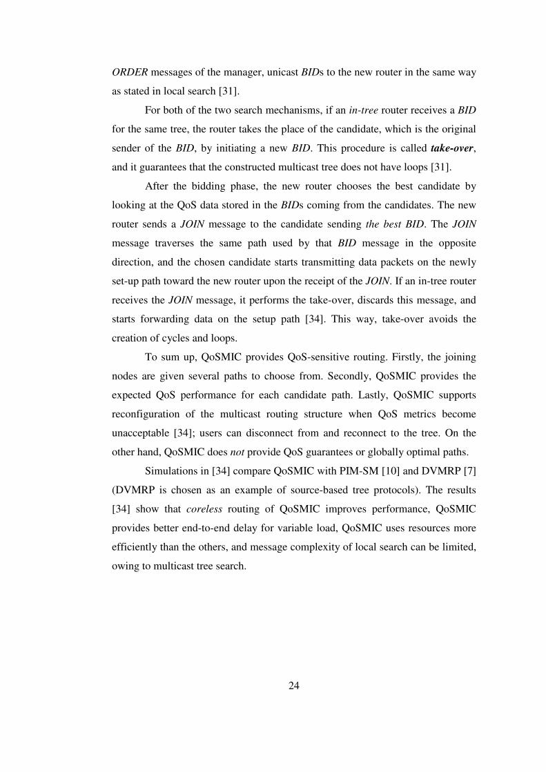
For both of the two search mechanisms, if an in-tree router receives a BID
for the same tree, the router takes the place of the candidate, which is the original
sender of the BID, by initiating a new BID. This procedure is called take-over,
and it guarantees that the constructed multicast tree does not have loops [31].
After the bidding phase, the new router chooses the best candidate by
looking at the QoS data stored in the BIDs coming from the candidates. The new
router sends a JOIN message to the candidate sending the best BID. The JOIN
message traverses the same path used by that BID message in the opposite
direction, and the chosen candidate starts transmitting data packets on the newly
set-up path toward the new router upon the receipt of the JOIN. If an in-tree router
receives the JOIN message, it performs the take-over, discards this message, and
starts forwarding data on the setup path [34]. This way, take-over avoids the
creation of cycles and loops.
To sum up, QoSMIC provides QoS-sensitive routing. Firstly, the joining
nodes are given several paths to choose from. Secondly, QoSMIC provides the
expected QoS performance for each candidate path. Lastly, QoSMIC supports
reconfiguration of the multicast routing structure when QoS metrics become
unacceptable [34]; users can disconnect from and reconnect to the tree. On the
other hand, QoSMIC does not provide QoS guarantees or globally optimal paths.
Simulations in [34] compare QoSMIC with PIM-SM [10] and DVMRP [7]
(DVMRP is chosen as an example of source-based tree protocols). The results
[34] show that coreless routing of QoSMIC improves performance, QoSMIC
provides better end-to-end delay for variable load, QoSMIC uses resources more
efficiently than the others, and message complexity of local search can be limited,
owing to multicast tree search.

25
3.2.3 QMRP
QMRP (QoS-aware Multicast Routing Protocol) [35] tries to achieve
scalability by reducing the communication overhead of constructing a multicast
tree. QMRP can switch between single-path routing and multi-path routing to
maintain a reasonably high success rate. Heuristic solutions to the NP-complete
Steiner tree problem cause excessive overhead, require global network
information management, and do not handle dynamic multicast group
membership. Hence, those heuristic solutions cannot be said to be practical for the
Internet applications. Also, QMRP is against relying on flooding. QoSMIC
alleviates flooding, but it has the disadvantage of using an extra global control
element (the Manager router) [34,35].
In QMRP, a new member joining a multicast group obtains the address of
the core of the tree by inquiring the Session Directory Protocol [48]. Then, the
new member starts routing process by sending a REQUEST message to the core
along the unicast path. There are two defined searching modes: Single-path mode
and multiple-path mode. The routing process begins with the single-path mode,
and only the known unicast routing path traversed by the REQUEST is considered
[35].
A REQUEST message carries the QoS requirement, i.e., a lower bound for
the desired bandwidth. As it travels along its path, it controls the resource
availability of every intermediate node or link, and moves forward if it finds out
that the required resources are available. If each node on its path has the required
resources, QMRP finds a feasible tree branch by traversing only a single path, as
PIM-like protocols [8,10,15,16] do.
If an intermediate node on the path does not have the required amount of
resources, it enters the multiple-path mode by sending a NACK (negative
acknowledgment) message back to the previous node. In response to the NACK,
the previous node forwards the current REQUEST toward directions other than the
previously defined unicast routing path. Thus, a node in the multiple-path mode
duplicates the REQUEST message and sends it to all of its neighbours except

26
those from which REQUEST and NACK messages have been received. When a
feasible branch is found, an acknowledgment (ACK) message is forwarded along
the branch towards the new member wishing to join the tree, as shown in Figure
3.2. When multiple ACKs converge at an intermediate node, the intermediate node
selects the best branch and rejects the others [35].
Figure 3.2 ACK follows the path of its REQUEST
QMRP adds new paths to the multicast search tree only when necessary,
and hence reduces tree construction overhead and achieves scalability. Success
rate can be maximized and efficiency can be increased by careful path selection,
i.e., by selecting only the best feasible path. Having no dependence on a global
control element like “the manager” [34] provides robustness to the protocol,
because a failure in a global control mechanism may lead to the total failure of a
routing protocol. For a specific request, intermediate nodes select only the best
ACK, and this guarantees loop-free tree construction. As a flexible multicast
routing protocol, QMRP can operate on any underlying unicast protocol; and it
can operate in both inter- and intra-domain levels with both shared-tree and
source-based tree approaches [35]. It improves its responsiveness and success rate
by using NACK messages to detect failure and avoiding the use of timeout [31].
In simulations [35], QMRP is compared with QoSMIC [31,34], Spanning
Joins [29] and ordinary single-path routing that involves trying a single unicast
routing path to joining the existing multicast tree. Experiments compare their
success ratio and overhead; and QMRP has the highest success ratio among the

27
four types of protocols. QMRP has the second best overhead results after single-
path routing, and this is an expected fact since single-path routing does nothing
but tests the unicast path between the new member and the core of the tree with
respect to QoS requirements of the new member [35].
3.2.4 S-QMRP
A QoS routing protocol is expected to favor a reasonable tradeoff between
routing overhead and the probability of finding a feasible path (i.e., success ratio).
In addition, a good routing protocol should minimize the extra state information
the protocol maintained in the network, spread the workload by distributing the
routing operations, and adapt the routing operations according to network
conditions.
QMRP [35] actually exhibits a good tradeoff between routing overhead
and success ratio, but it has two main problems. First, for each join request,
QMRP stores temporary states in routers. It is desired that routers maintain
information for each multicast session, instead of each request in each group.
Second, QMRP provides QoS for applications with non-additive QoS metrics
such as bandwidth and buffer space, and suffers from the lack of the mechanism
to handle additive QoS requirements such as delay. Spanning Joins [29] and
QoSMIC [34] do not suffer from these problems, but they result in higher routing
overhead and lower success ratio values [35].
S-QMRP (Scalable QoS Multicast Routing Protocol, also called SoMR)
has appeared in [36] and has been published later in [49]. It is a scalable, stateless
QoS Internet multicast routing protocol that shares the same idea with QMRP, but
eliminates the temporary state usage for join requests. QMRP initiates a new
search tree for each new member to connect the multicast tree, and the initiated
search tree grows towards the existing multicast tree. On the contrary, S-QMRP
eliminates the search tree, and the multicast tree grows toward new members. The
protocol stores no routing state other than the multicast tree. In addition, it also
allows aggregation of join requests, in such a way that a single tree branch may
28
grow towards more than one new member. S-QMRP uses an early-warning
(EW) mechanism, takes the additive delay requirement into account, and
identifies the most suitable point to search for additional paths in order to increase
success probability [36].
S-QMRP has mainly two phases. In the first phase, a JOIN message is sent
from a new member to the root of the multicast tree along the unicast routing path,
and again the JOIN message keeps the information of its path and the
accumulated delay on the path it traverses. If the message reaches an in-tree node,
and if the sum of the accumulated delay collected on the message and the in-tree
delay from the root to this in-tree node does not violate the delay requirement, the
path traversed by the JOIN message is considered to be feasible. In that case, the
in-tree node, which is the receiver of the JOIN message, sends a
CONSTRUCTION message back along the same path to the new member [36].
Contrary to the operation when the delay requirement is satisfied, if the
delay requirement is violated at the in-tree node, the original JOIN message
continues traveling to the root of the tree. The second phase of S-QMRP operation
begins when the root receives the JOIN. The root then sends GROW messages to
its neighbours and starts multi-path routing as a result. The GROW messages are
destined for the new member and travel along the unicast routing paths. Each
GROW message carries the delay requirement and accumulates the delay of the
tree branch so that a node receiving a GROW learns the total delay in the tree from
the root to itself. When a GROW message arrives at an intermediate node i, that
node i performs an EW test to check if the unicast path will satisfy the delay
requirement D. If the EW test succeeds, routing continues along the path to the
new member. If the test fails, node i starts multi-path routing and possibly
constructs multiple downstream paths approaching to the new member. To
illustrate, if j is the next hop on the unicast path from the root to the new member,
the EW test has four parameters, D, delay(root,i), delay(i, j), and L, which is the
number of hops from i to the new member. The representation delay(n,m) stands
for the delay on the path connecting nodes m and n. The EW test is defined as

29
follows: if “delay(i,j) is greater than (D-delay(root,i))/L” then give a warning;
continue otherwise [36].
The EW test finds the remaining part of the total delay requirement as
(D-delay(root,i)), and divides it by the remaining number of hops to find the
average delay on a link of the rest of the unicast path. If the delay of the current
link is smaller than the share of each future link, the test is successful [36].
If the GROW message passes the EW test, node i adds the link between j
and itself to the multicast tree and forwards the GROW to the determined next
router j. A feasible branch can be set up if and only if the GROW message passes
the EW test at each intermediate node [36].
On the other hand, if the EW test warns that the remaining unicast routing
path may not satisfy the QoS requirement, GROW messages are sent to each
adjacent node n that satisfies the following QoS test: if “delay(i,n) is greater than
(D-delay(root,i))” then count this as a failure; continue otherwise [36].
Obviously, n cannot be the node which has just sent the current GROW to
i. If this QoS test fails for each neighbouring node, then a BREAK message is sent
back to the root to remove the constructed branches. When an upstream node k
receives BREAK message from a downstream node i, it first deletes the link
connecting the two nodes from the multicast tree [36]. As a result of this
extraction, if k becomes a leaf node and if it is not a member of the multicast
group, it leaves the multicast tree and continues to forward the BREAK message to
its in-tree parent.
In brief, the EW test makes an early guess on the chance of satisfying the
delay constraint for the path from the root to the new member, and initiates
branching if necessary, in order to improve the success probability. The QoS test
checks if the delay requirement has already been violated. In the beginning of the
second routing phase, S-QMRP causes the root to be a branching point, and an
EW test is not necessarily performed at that point. It is shown with simulations
that S-QMRP performs better this way, because branching out early at the root
expands the feasible path search range and provides more choices for flexibility
[49].
30
The receipt of a GROW message by the new member shows the successful
establishment of a feasible tree branch. If the new member receives more than one
GROW, it sends BREAK along all paths except the path of the best GROW
message, so as to prune the undesired branches. Many temporary branches may be
chosen as a result of a single JOIN, but each node keeps only one entry (one per
group), and unlike QMRP, it does not keep information on each particular JOIN
[35]. Therefore, the memory used on a router by a multicast group is constant and
independent of the number of simultaneous join requests. In the simulations [36],
success ratio and message overhead of S-QMRP are compared with those of
QoSMIC [34], Spanning Joins [29], and traditional Single (or, Shortest) Path
Routing. In conclusion, S-QMRP is shown to have better performance than the
other protocols considered, but the proposed advantages [36] of S-QMRP over
QMRP [35] are not proven.
3.2.5 QROUTE
QROUTE [37,38] is designed for QoS-guaranteed multicast routing, and
constructs a feasible multicast tree with as many QoS constraints as required using
local states at routers. Its simple design and implementation has been
demonstrated via experiments on a constructed prototype router testbed [38].
QROUTE increases success ratio and network resource usage efficiency by
searching for all possible feasible paths in parallel, but avoids flooding data
packets blindly.
A host that wants to join a multicast tree sends a REQUEST packet to all
of its neighbouring routers. The REQUEST packet collects the QoS information
along the routing path it follows. A router receiving a REQUEST processes it as
follows [38]:
i. If it has already received the same request, it sends back a PRUNE-
BACK packet immediately; otherwise, it continues to steps (2) and (3).
ii. If this router is not an in-tree router, it performs QoS constraints test
and hop bound test. According to the results of the tests, the router
31
either sends back a PRUNE-BACK or sends the REQUEST to all of its
neighbour routers after reserving the required resources tentatively.
The REQUEST is not sent back again to the router from which it has
just been received.
iii. If this router is an in-tree router, this means that the REQUEST has just
reached the multicast tree. This time, only the QoS constraints test is
executed to see if the QoS constraints of the new host can be satisfied.
In order to determine whether the QoS constraints can be met, the QoS
information gathered in the REQUEST packet and the QoS information
about the multicast tree path from the root to this router are used. If it
is found that the requirements are satisfied, commits the required
resources and sends back a CONFIRM packet to the neighbour from
which it has received the REQUEST; otherwise a PRUNE-BACK
packet is sent instead. Whether CONFIRM or PRUNE-BACK, the final
destination of the packet sent back by the in-tree router is the new
member that is the original sender of the REQUEST.
A router that receives a CONFIRM packet joins the multicast tree, reserves
resources tentatively, and forwards the CONFIRM to its neighbor from which it
previously received the newly confirmed REQUEST packet. When a CONFIRM
reaches the new member, the feasible path searching process succeeds. If a router
receives a PRUNE-BACK packet from one of its neighbours, this means that the
REQUEST forwarded in that direction has failed to find a feasible path. If
PRUNE-BACK packets arrive from all the neighbours that a router has sent
REQUESTs to, the router releases all the tentatively reserved resources, and sends
backward the PRUNE-BACK packet to the downstream neighbour from which the
REQUEST was received [38].
The operation of QROUTE is evaluated [38] by comparing it with other
related protocols, and it is found that the tree establishment procedure of
QROUTE has higher success ratio, lower packet overhead, and lower connection
setup latency than those of the other protocols used in simulations. The results of
the simulations also show that QROUTE constructs multicast trees with generally

32
fewer links than the other protocols under investigation, and its performance is
scalable with the network sizes [38].
With respect to its characteristics, improvements, experimental
computations and performance, QROUTE is considered to be an important
example of Internet QoS multicast routing protocols, and its operation will be
described in much more detail with all of its pros and cons in Chapter 4.
3.2.6 QMBF
QMBF [39] is a QoS-aware multicast protocol based on a bounded
flooding technique. Every node keeps the knowledge of the topology and QoS
information of a local network cell (LNC) around itself. With this knowledge,
QMBF aims to increase success probability and to decrease packet overhead
while maintaining scalability. QMBF is also flexible; its design allows QMBF to
be able to operate on top of any underlying unicast routing protocol, or to
cooperate with a QoS-based unicast routing protocol.
QMBF uses different aspects of source-based routing and QoS-aware
routing [40] to search for feasible branches. Each node performs a bounded
broadcast to a scope called local network cell, and tells to its neighbours about its
local QoS state and least-cost reachability information. Local QoS state is the
information on the QoS conditions of a node itself and of its outgoing links.
Reachability information tells the nodes that a router can reach through its
neighbours. Least-cost reachability information includes the set of nodes that
have the least-cost paths towards the multicast source in the local network cell of
a node. Every node learns the topology and QoS conditions surrounding it with
the help of these broadcast messages [39].
If a host wants to join a multicast group, it checks if some of its edge
nodes have least-cost paths to the target router. If so, the joining node sends its
request to those edges along feasible paths. Otherwise, the node locates feasible
33
paths toward all (or, some) of its edge nodes and sends the request to the selected
edge routers [39].
The tree construction in QMBF starts with a multicast tree with only one
group member, the multicast source. Whenever a new node wishes to join the
group, QMBF tries to find a feasible branch that can connect the new member to
one of the nodes that are already in this group’s multicast routing tree. For
scalability and high success rate, QMBF uses M-hop bounded flooding technique.
It is assumed that every node has the QoS state information of itself and its
outgoing links; that is, every node has the knowledge of its local QoS state. In M-
hop bounded flooding, each node broadcasts its local QoS state and reachability
information (the nodes it can reach through each of its neighboring nodes with
unicast routing) periodically. These messages are forwarded for at most M-hops,
where M is determined according to the current network conditions. The region of
the network, in which those bounded flooding messages travel, is called the local
network cell (LNC) [39]. The node, from which those messages originate, is the
center of its LNC, and its LNC is said to have a radius of M-hops. Nodes that are
the last nodes for bounded flooding messages are called edge nodes for the LNC
of the center node.
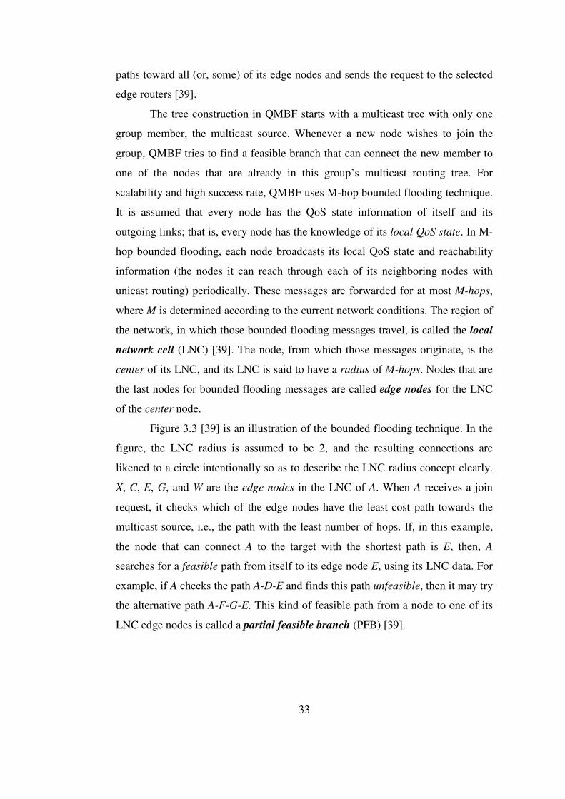
Figure 3.3 [39] is an illustration of the bounded flooding technique. In the
figure, the LNC radius is assumed to be 2, and the resulting connections are
likened to a circle intentionally so as to describe the LNC radius concept clearly.
X, C, E, G, and W are the edge nodes in the LNC of A. When A receives a join
request, it checks which of the edge nodes have the least-cost path towards the
multicast source, i.e., the path with the least number of hops. If, in this example,
the node that can connect A to the target with the shortest path is E, then, A
searches for a feasible path from itself to its edge node E, using its LNC data. For
example, if A checks the path A-D-E and finds this path unfeasible, then it may try
the alternative path A-F-G-E. This kind of feasible path from a node to one of its
LNC edge nodes is called a partial feasible branch (PFB) [39].

34
X
C
E
B
A
Y
D
F
G
Z
W
Figure 3.3 An illustration of Bounded Flooding technique
QMBF uses the LNC knowledge to search for feasible paths. A join
request travels step by step along an M-hop path to the target router, where M is
the LNC radius. This approach is expected to locate a feasible branch quickly and
increase the success ratio [39].
In [39], a single-path joining protocol (Shortest Path Routing), Spanning-
Joins [29], QMRP [35,40] and QMBF are implemented on network simulator-2,
and simulations are conducted on the Waxman network topology [41]. “Success
rate” is defined as the ratio of the number of successful trials in finding a feasible
branch to the total number of searching attempts [39]. The results in those
experiments show that QMBF has the best success ratio among the protocols used
in the simulations.
QMBF is going to be presented in detail in Chapter 4.
3.3 Protocol Classification and Comparison
Traditional multicast routing protocols, such as CBT [11,12,15,16] and
PIM [8,10,15,16], were designed for routing and delivery of best effort traffic, and
they focus on connectivity instead of QoS requirements. On the other hand, QoS-

35
based multicast routing produces a feasible multicast tree that has sufficient
resources to meet the link and tree constraints like link bandwidth and end-to-end
delay [42].
Current solutions for QoS multicast routing can be classified into two
main groups: QoS-sensitive and QoS-aware routing protocols [37]. A QoS-
sensitive multicast routing protocol searches for feasible paths without reserving
the required resources, and collects information on network conditions. It is
typically the new host who makes the selection among paths satisfying the QoS
requirements. At the end of the procedure, the new host sends a connection
request along its selected path. For example, YAM [29] protocol floods the
network with request packets to locate in-tree nodes. An in-tree node receiving a
request packet sends back a reply that collects the QoS information on the existing
links. In the case of receiving more than one reply, the new member chooses the
most feasible path among all candidate paths before. QoSMIC [31,34] protocol
brings some improvements to YAM by providing multicast tree search to limit
local search, and hence, to reduce the flooding overhead caused in the local
search. To sum up, YAM and QoSMIC select their candidate paths among the
unicast routing paths from the selected in-tree nodes to the new member, and the
paths are usually the shortest paths in terms of the number of hops. However, the
selected paths may be unsuitable for QoS requirements, and these two protocols
cannot be classified as QoS-aware.
On the other hand, QoS-aware multicast routing protocols check QoS
constraints according to available network resources while they are searching for
feasible paths to connect a new member to an existing multicast tree. In path
selection phase, only paths that meet the required constraints are taken into
account by the candidate host. Finally, a connection request is sent along the path
selected in the previous phase. An example protocol is QMRP [35], in which only
non-additive QoS properties, i.e., bandwidth metrics, are considered. In QMRP, a
join request is routed using unicast from the new member generating the request
towards the root of the multicast tree. A node on the unicast path forwards the
request to the next node only when enough resources exist. Otherwise, the join
36
request is rejected at that point, and the preceding node sends the same request to
all of its neighbours other than the one that rejected the request. Each of those
requests is again routed with unicast routing to the root. In S-QMRP [36]
protocol, a new member sends its request to the multicast source by using the
underlying unicast routing protocol and determining the shortest path. Hence, if
network resources on that path satisfy the QoS constraints of the new member,
then S-QMRP operates in the same way as SPR. However, if the QoS constraints
cannot be met, the root sends GROW messages to its neighbours upon the receipt
of the join request, and GROW messages travel along unicast routing paths in the
backward direction towards the new member. On each of the unicast paths,
GROW messages are forwarded according to the results of early warning tests
performed by each router to check the validity of QoS support. When a GROW
reaches the new member, a connection can be established on the path followed by
that GROW message. In QGMRP [32], a host wishing to join a multicast tree
sends its request to the source along again the shortest unicast path. The request
carries the QoS requirements, and collects QoS parameters on its way. Each router
on the path of the request compares the QoS parameters gathered by the request
with the QoS requirements of the new member, and either forwards or rejects the
request. A node that receives rejection information starts multi-branch searching.
QGMRP, QMRP and S-QMRP are QoS-aware, and try a subset of the
feasible paths in order to reduce routing overhead by switching between single-
path and multi-path search. They tend to reach the root of the multicast tree, and
the resulting trees possibly use more links and resources, degrading the final
performance. More precisely, these protocols provide best-effort multicast service
unless some resource reservation protocol (such as RSVP [43]) tries to reserve the
required resources after a request is accepted by the tree. Even the acceptance of a
request may fail if some other process starts to use the required resources in the
duration between the propagation of a request to the root and resource allocation
after acceptance.
A different approach to multicast routing is constructing a feasible tree
that guarantees to meet multiple QoS constraints and resource requirements using

37
local states at routers. QROUTE [37,38] and QMBF [39] use this approach, and
hence they can be classified as QoS-guaranteed multicast routing protocols.
QROUTE uses a two-state reservation method. It reserves network
resources tentatively [37] while searching for feasible paths for a new member,
and then commits [37] the resource reservations upon confirmation of the
connection request. The objective of tentative reservations is preventing the
required resources from being reserved by new join requests; that is to say, the
resources are kept dedicated to the current connection request until a confirmation
or a rejection response. Still, the resources can be utilized by only best-effort
network traffic without causing much problem. QROUTE avoids over-reservation
problem by QoS constraint tests and improved responsiveness, and hence, does
not lead to inefficient use of network resources.
QMBF combines source-based routing and QoS-aware routing in feasible
path search [39]. In QMBF, every node informs the nodes around itself about its
local QoS state and least-cost reachability information. Using this bounded
flooding technique, every node knows about its local network cell (LNC). A
router receiving a join request checks if the required resources are available. If so,
the resources are maintained for this request, and they are not available for
another QoS connection request. That is, when the request is confirmed by the
multicast tree, no resource unavailability problem occurs. Hence, QMBF shares
the same idea of QoS-guaranteed tree construction with QROUTE, and the only
differences are bounded flooding and local network cell approaches.
The QoS multicast routing protocols discussed here are briefly
summarized and compared in Table 3.1. Table 3.1 describes these protocols
according to their multicast routing approaches, the control messages they use,
their tree construction mechanisms, the QoS constraints they consider, their
constructed tree types, characteristic properties, and the protocols they are built on
(if there is any). The network models used in their simulations, the protocols they
are compared with, analyses and results, advantages, disadvantages, open points,
and possible future work are also discussed in Table 3.1, according to the results
of our extensive literature survey.
38
The network models used in literature are based on mainly Waxman [41],
MBone [44], and Power-Law [45] topologies. The resulting analyses and their
positive or negative results are discussed in Table 3.1. Still, there are some
missing or unclear parts in the protocol descriptions or in simulations. For
example, in [32], path selection criteria from a new member to the source are not
discussed. In [37] and [38], the benefits of QROUTE are not stated explicitly, and
how the simulations were carried out is a remaining question. In [35] and [36],
state reduction is not considered, and the necessity of one state in the 5-state finite
state machine is thought to be an open point. QMBF is said to reserve resources
for a request before the connection is established, but this is not one of the
explained characteristics in [39]. In [36], information about simulations has some
missing parts like the group sizes used, and the reasoning on compared protocols
seems to be not complete.
The analyses stated in “Possible Work” row of Table 3.1 may be carried
out to have a better understanding and comparison of QoS Internet multicast
routing protocols. Working on those cases and characteristics can also fulfill some
missing information on the protocols, such as the disadvantages of QoS-
guaranteed protocols, their pros and cons, and the network environments they best
fit in.
As a result of this summary table, this thesis work aimed at analyzing and
comparing two more recently proposed protocols, namely QROUTE and QMBF,
in detail.

39
SoMR (S-QMRP)
QoS-Aware: QoS reqs. are checked when forwarding request toward the tree. Needs RSVP for QoS
JOIN, CONSTRUCTION, GROW, BREAK
New member sends JOIN to the root along the unicast routing path. When an in-tree router receives JOIN, it checks the total delay. If OK, it sends back CONSTRUCTION. Otherwise, the JOIN is sent to the root, and the root sends GROW to all its neighbours. GROWs travel along the unicast path to the new member. Nodes which receive GROW perform EW tests and either forward GROW or send back BREAK.
QMBF
QoS-Guaranteed: possibly no need for RSVP to provide QoS on resource reservation
join, confirm, unack, prune
Every node periodically broadcasts its QoS state and least-cost reachability to its LNC. A new member looks for least-cost & feasible edge routers of its LNC and forwards its request. When the join request passes all tests and reaches an in-tree router, a confirm msg is sent back. When all neighbouring branches of a node fail, it sends back unack.
QMRP
QoS-Aware: QoS reqs. are checked with forwarding request toward the tree. Needs RSVP for QoS
request, ack, nack, break
New member sends request along the shortest unicast path to the source. Request collects QoS info, and each node forwards the request after some resource check. An ack is returned back, if the request succeeds. Modeled with a five-state finite state machine
QROUTE
QoS-Guaranteed: no need for RSVP to provide QoS on resource reservation
request, confirm, prune-back, prune-branch
New router sends request to all of its neighbours. Prune-back is sent back if this request has been received twice or QoS-reqs are not satisfied on all outgoing branches. A router performs QoS (and hop bound) tests and forwards the request accordingly. QROUTE searches for the shortest path to the tree.
QoSMIC
QoS-Sensitive: QoS metrics are accumulated when bids are sent back to the new member
BID_REQ, M_JOIN, BID_ORDER, BID, JOIN, PRUNE
New member sends M_JOIN to the Manager and broadcasts BID_REQ locally. BIDs come from some in-tree routers to the new router with QoS info they collected on their unicast path. The new member selects best BID and sends JOIN to the sender of the best BID.
QGMRP
QoS-Aware: QoS reqs. are checked with forwarding request toward the tree. Needs RSVP for QoS
rqst, rply, rjct
New member forwards rqst along the shortest unicast path to the SOURCE. Each router checks QoS parameters and either forwards rqst or sends back rjct. A node which receives a rjct branches out. The source sends back a rply/rjct, and the (sub)optimal path among feasible paths will be selected by the new router.
Table 3.1 Description and Comparison of QoS Multicast Routing Protocols
QoS Protocol:
Family:
Messages:
Description:

40
SoMR (S-QMRP)
Delay
Both
EW tests, Root is a mandatory branching pt for flexibility, BREAK is used to select the best branch at the new member, S-QMRP-m optimization (MBL, MBD)
QMRP
QMBF
Anything
Both
Local Network Cell (LNC), Optimization QMBF-mn (flooding hops and MBL)
QMRP
QMRP
Bandwidth
Both
Five-state finite-state machine: (S, F, SP, MP, I), Restricted QMRP-m (MBD=10 and MBL=2, i.e., QMRP-2)
none
QROUTE
Anything
Both
Resource reservation, QoS constraint tests, Bounded routing, Loop avoidance, Concurrent joins, Implicit and explicit prune-back
none
QoSMIC
Delay (others may also be used)
Both
Manager router: local search + multicast tree search, Candidate selection, Take-over, Loop avoidance
Spanning Joins and YAM
QGMRP
Delay, jitter, bandwidth, (loss), cost
Both
Unlike the others, join request must reach the source; it is not sufficient to reach an in-tree router
QMRP
Table 3.1 (continued) Description and Comparison of QoS Multicast Routing Protocols
QoS Protocol:
QoS constraints:
Shared / Source-Based Tree:
Characteristics:
Based on:
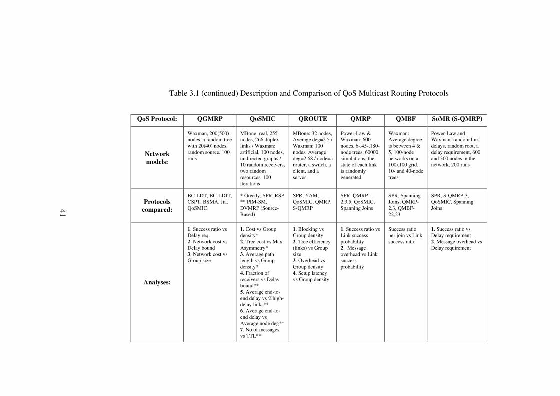
41
SoMR (S-QMRP)
Power-Law and Waxman: random link delays, random root, a delay requirement, 600 and 300 nodes in the network, 200 runs
SPR, S-QMRP-3, QoSMIC, Spanning Joins
1. Success ratio vs Delay requirement 2. Message overhead vs Delay requirement
QMBF
Waxman: Average degree is between 4 & 5, 100-node networks on a 100x100 grid, 10- and 40-node trees
SPR, Spanning Joins, QMRP-2,3, QMBF-22,23
Success ratio per join vs Link success ratio
QMRP
Power-Law & Waxman: 600 nodes, 6-,45-,180-node trees, 60000 simulations, the state of each link is randomly generated
SPR, QMRP-2,3,5, QoSMIC, Spanning Joins
1. Success ratio vs Link success probability 2. Message overhead vs Link success probability
QROUTE
MBone: 32 nodes, Average deg=2.5 / Waxman: 100 nodes, Average deg=2.68 / node=a router, a switch, a client, and a server
SPR, YAM, QoSMIC, QMRP, S-QMRP
1. Blocking vs Group density 2. Tree efficiency (links) vs Group size 3. Overhead vs Group density 4. Setup latency vs Group density
QoSMIC
MBone: real, 255 nodes, 266 duplex links / Waxman: artificial, 100 nodes, undirected graphs / 10 random receivers, two random resources, 100 iterations
* Greedy, SPR, RSP ** PIM-SM, DVMRP (Source-Based)
1. Cost vs Group density* 2. Tree cost vs Max Asymmetry* 3. Average path length vs Group density* 4. Fraction of receivers vs Delay bound** 5. Average end-to-end delay vs %high-delay links** 6. Average end-to-end delay vs Average node deg** 7. No of messages vs TTL**
QGMRP
Waxman, 200(500) nodes, a random tree with 20(40) nodes, random source. 100 runs
BC-LDT, BC-LDJT, CSPT, BSMA, Jia, QoSMIC
1. Success ratio vs Delay req. 2. Network cost vs Delay bound 3. Network cost vs Group size
Table 3.1 (continued) Description and Comparison of QoS Multicast Routing Protocols
QoS Protocol:
Network models:
Protocols compared:
Analyses:
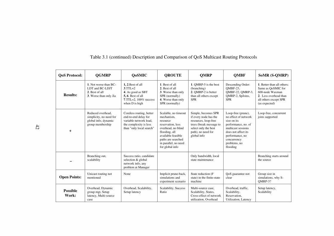
42
SoMR (S-QMRP)
1. Better than all others; Same as QoSMIC for 600-node Waxman 2. Less overhead than all others except SPR (as expected)
Loop-free, concurrent joins supported
Branching starts around the source
Group size in simulations, why S-QMRP-3?
Setup latency, Scalability
QMBF
Descending Order: QMBF-23, QMBF-22, QMRP-3, QMRP-2, SpJoins, SPR
Loop-free (prune), no effect of network size on its performance, no. of multicast sessions does not affect its performance, no concurrency problems, no flooding
QoS guarantee not clear
Overhead, traffic, Scalability, Reservation, Utilization, Latency
QMRP
1. QMRP-5 is the best (branching) 2. QMRP-2 is better than all others except SPR
Simple, becomes SPR if every node has the resources, loop-free trees (break message to select only the best path), no need for global info
Only bandwidth, local state maintenance
State reduction (F state) in the finite-state machine
Multi-source case, Scalability, States, Cross-effect of network utilization, Overhead
QROUTE
1. Best of all 2. Best of all 3. Worse than only SPR (normally) 4. Worse than only SPR (normally)
Scalable, no timeout mechanism, resource reservation, less overhead, no blind flooding, all available feasible paths are searched in parallel, no need for global info
Implicit prune-back, simulations and experiment scenario
Scalability, Success Ratio
QoSMIC
1, 2.Best of all 3.TTL=2 4. As good as SBT 5, 6. Best of all 7.TTL=2, 100% success when D is high
Coreless routing, better end-to-end delay for variable network load, the complexity is less than "only local search"
Success ratio, candidate selection & global network info, any problem at Manager
None
Overhead, Scalability, Setup latency
QGMRP
1. Not worse than BC-LDT and BC-LDJT 2. Best of all 3. Worse than only Jia
Reduced overhead, simplicity, no need for global info, dynamic group membership
Branching out, scalability
Unicast routing not mentioned
Overhead, Dynamic group mgt, Setup latency, Multi-source case
Table 3.1 (continued) Description and Comparison of QoS Multicast Routing Protocols
QoS Protocol:
Results:
+
–
Open Points:
Possible Work:

43
CHAPTER 4
QROUTE AND QMBF
In Chapter 3, some important QoS multicast routing protocols were
described and compared. The results summarized in Table 3.1 show that two of
those protocols, namely QROUTE and QMBF, need to be analyzed more
thoroughly for a better understanding. This is because they are proposed as
QoS-guaranteed [37] multicast routing protocols, and the pros and cons of their
techniques must be discussed, compared and proven.
In this chapter, first, QROUTE will be described in detail. The technique
will be presented, some details will be shown, and analyses will be discussed with
resulting advantages or disadvantages. Then the same approach is going to be
applied to QMBF [39].
4.1 QROUTE
4.1.1 Description
In a multicast backbone network, there are two kinds of nodes, namely
hosts and routers. The word node can also be used interchangeably with router.
Hosts are the end points in a multicast tree, which generate or receive traffic.
Routers (Nodes) are responsible for the efficiency, accuracy, and possibly QoS
control of traffic flow in the network of hosts. Routers are interconnected by a set
of full-duplex links to form the backbone of the network. Each host communicates
with other host in the backbone through its default gateway.

44
Table 4.1 Summary of control packets in QROUTE
Packet Type Description
Request To search for paths Confirm To confirm paths
Prune-Back To notify failure Prune-Branch To leave the tree
Four kinds of control packets are used in QROUTE, as shown in Table 4.1
[37]. When a host wants to join a multicast tree, it sends a REQUEST packet to its
default gateway. The default gateway router then sends the REQUEST to all
neighbours (Figure 4.1-a). The REQUEST accumulates QoS information on its
path. If a router receives a REQUEST packet, first of all, it checks whether it has
already received this REQUEST before. If it has already received this join request
originating from the same new host with the same QoS requirements for the same
multicast group, it sends back a PRUNE-BACK packet (Figure 4.1-b). If this
router receives this REQUEST for the first time, it performs QoS constraint and
hop bound tests if the router is not an in-tree router. If both of these tests are
successful, the router performs tentative resource reservation and forwards the
REQUEST message to all of its neighbours other than the one from which the
recent REQUEST packet has been received (Figure 4.1-c); otherwise, it sends
back a PRUNE-BACK (Figure 4.1-b). On the other hand, if the router is an in-tree
router, it only performs QoS constraint tests using the information accumulated in
the REQUEST. If the REQUEST passes the QoS constraint tests, the router
allocates the required resources and sends a CONFIRM packet backward to the
new host (Figure 4.1-d). This CONFIRM holds the QoS information from the
source to its generator. If the QoS tests fail, a PRUNE-BACK packet is sent back
instead of the confirmation message [38].

45
New
host
Request
Request
Request
Request
Request
Prune Back
Request
Request
Request
Request
Request
Confirm
Default
gateway for
the new host
in-tree routers
(a)
(d)(c)
(b)
Figure 4.1 The basic operations of QROUTE
A router receiving a CONFIRM for a previously forwarded REQUEST
packet becomes an in-tree router, commits the tentative resource reservation, and
forwards the CONFIRM packet downstream along the path followed by the
REQUEST (Figure 4.1-e). When the new member receives a CONFIRM, this
shows that a feasible path for the new member is found. On the contrary, a router
releases all of its tentatively reserved network resources when it receives
PRUNE-BACK from all of its neighbours; because, receiving a PRUNE-BACK
shows the failure of the forwarded REQUEST in finding a feasible path along that
direction. After releasing previously allocated resources, the router delivers the

46
PRUNE-BACK packet back to the sender of the REQUEST (Figure 4.1-f). If the
new member receives PRUNE-BACK from all of its neighbours, then the feasible
path search process completely fails [38].
Figure 4.1 (continued) The basic operations of QROUTE
As the last operation, if a leaf host wants to leave its multicast tree, it
sends a PRUNE-BRANCH packet to its default gateway (Figure 4.1-g), and the
PRUNE-BRANCH causes upstream in-tree routers to release reserved resources.

47
An in-tree router receiving a PRUNE-BRANCH forwards the packet to its in-tree
parent if it becomes a leaf (Figure 4.1-h).
Resource reservation approach guarantees the satisfaction of QoS
constraints for a connection by giving a share of certain resources to QoS
applications. In the cases of QoS-sensitive and QoS-aware routing, a path is
selected and the connection is established with the required resources reserved by
a resource reservation protocol, such as RSVP [43]. Nevertheless, changes in the
availability of resources may lead to a failure of the final connection due to the
lack of the previously considered but not reserved resources. Various solutions
[46] have been proposed to solve the problems of setup, reservation, and call
admission, but those solutions assume that static conditions exist where multicast
sessions are known and fixed. Furthermore, QoS-guaranteed routing must avoid
the over-reservation problem, which is not considered in those previous solutions
[38].
QROUTE makes a summary of required resource usage along with
solutions for how to meet the constraints during the feasible path search phase and
gives those resources entirely to the QoS application in the connection-confirming
phase. As a consequence of this two-phase reservation procedure, QROUTE
guarantees a QoS connection from the moment an attachment point is found until
the end of the connection session. In addition, QROUTE solves the problem of
over-reservation with QoS constraint tests and immediate responding, and lets all
applications use resources much more efficiently [37,38].
The QoS constraint tests in QROUTE perform admission control and
reduce routing overhead. Admission control is provided by accepting only the join
requests that pass the tests. Additionally, the tests terminate searching for feasible
paths for which there is no guarantee for satisfying the QoS requirements, and
hence, the number of packets sent for the search is reduced [38].
QROUTE allows multiple QoS constraint tests to be performed at each
node by working with cooperative scheduling algorithms at nodes. For example,
QROUTE can be used with rate-proportional schedulers [47] and with the leaky
bucket algorithm. The bandwidth test checks if the unreserved, i.e., free, capacity
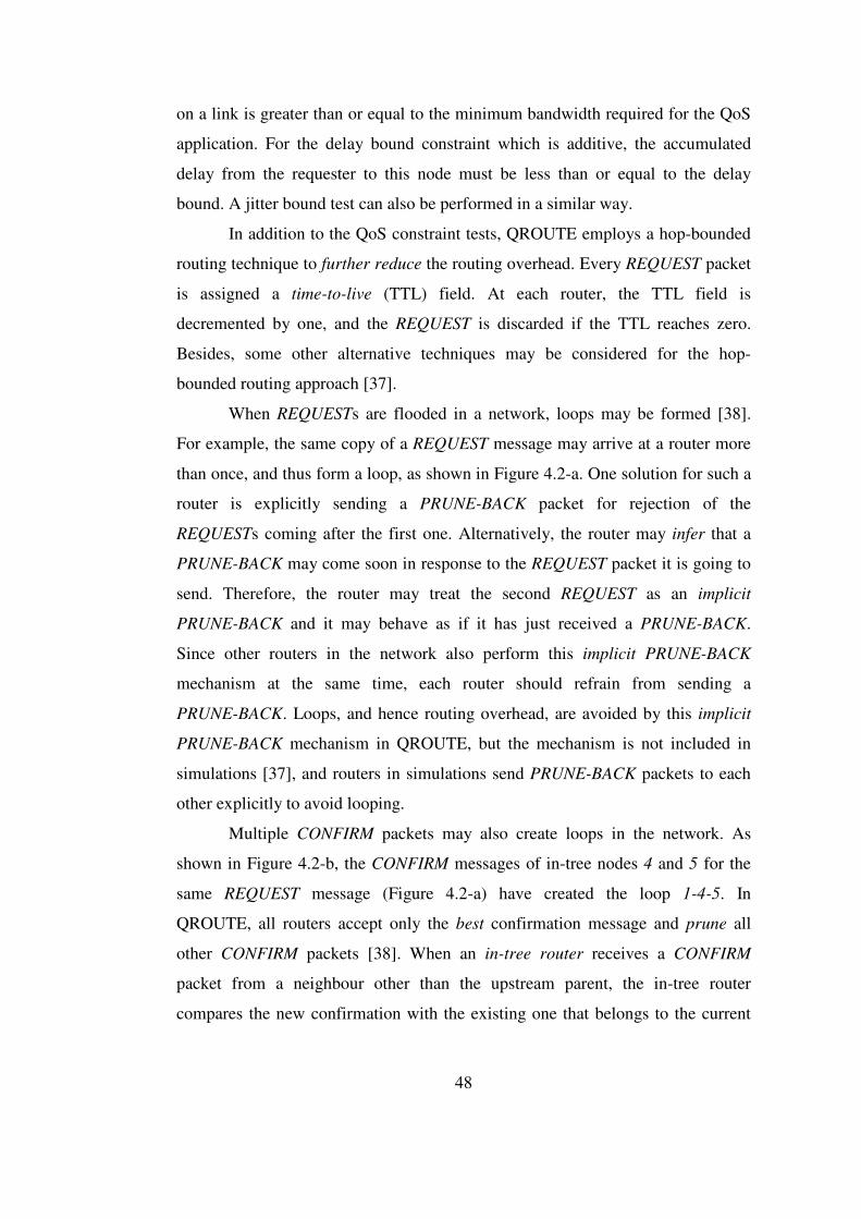
48
on a link is greater than or equal to the minimum bandwidth required for the QoS
application. For the delay bound constraint which is additive, the accumulated
delay from the requester to this node must be less than or equal to the delay
bound. A jitter bound test can also be performed in a similar way.
In addition to the QoS constraint tests, QROUTE employs a hop-bounded
routing technique to further reduce the routing overhead. Every REQUEST packet
is assigned a time-to-live (TTL) field. At each router, the TTL field is
decremented by one, and the REQUEST is discarded if the TTL reaches zero.
Besides, some other alternative techniques may be considered for the hop-
bounded routing approach [37].
When REQUESTs are flooded in a network, loops may be formed [38].
For example, the same copy of a REQUEST message may arrive at a router more
than once, and thus form a loop, as shown in Figure 4.2-a. One solution for such a
router is explicitly sending a PRUNE-BACK packet for rejection of the
REQUESTs coming after the first one. Alternatively, the router may infer that a
PRUNE-BACK may come soon in response to the REQUEST packet it is going to
send. Therefore, the router may treat the second REQUEST as an implicit
PRUNE-BACK and it may behave as if it has just received a PRUNE-BACK.
Since other routers in the network also perform this implicit PRUNE-BACK
mechanism at the same time, each router should refrain from sending a
PRUNE-BACK. Loops, and hence routing overhead, are avoided by this implicit
PRUNE-BACK mechanism in QROUTE, but the mechanism is not included in
simulations [37], and routers in simulations send PRUNE-BACK packets to each
other explicitly to avoid looping.
Multiple CONFIRM packets may also create loops in the network. As
shown in Figure 4.2-b, the CONFIRM messages of in-tree nodes 4 and 5 for the
same REQUEST message (Figure 4.2-a) have created the loop 1-4-5. In
QROUTE, all routers accept only the best confirmation message and prune all
other CONFIRM packets [38]. When an in-tree router receives a CONFIRM
packet from a neighbour other than the upstream parent, the in-tree router
compares the new confirmation with the existing one that belongs to the current

49
multicast traffic, and it accepts the better CONFIRM (Figure 4.2-c and Figure 4.2-
d).
A
CB
1
53
42
1
53
42
1
53
42
Request
Request
Request
in-tree
routers
routers receive
Confirm and join
the tree
Request
Request
Request
Request
Confirm
Confirm
Confirm
Confirm
Prune Back
Prune Back
(a) (b)
(c) (d)
node 3 leaves the tree
Figure 4.2 Causes of loops and loop avoidance in QROUTE QROUTE also supports simultaneous join requests of multiple hosts to the
same multicast tree, and a pre-merging technique is proposed here, again to
reduce the routing overhead. The reasoning in [37] can be applied to a scenario
where a REQUEST carrying a specific bandwidth constraint and a nonadditive
QoS metric arrives at a router twice. The pre-merging test checks if the first
REQUEST packet is better. That is, it checks whether the difference between the
maximum and the so far accumulated additive QoS constraints carried on the
packet is more than that of the second packet. If the test is successful, the second
packet, instead of being forwarded as usual, waits to use the routing result of the

50
first packet. If, subsequently, a PRUNE-BACK packet for the first REQUEST is
received, the path is viewed as unsuitable for the second one. On the other hand, if
a CONFIRM packet for the first REQUEST is received, one more test is needed to
check whether the selected path can provide the required resources for the second
one. The additional test depends on the resource information carried in the
confirmation message and the accumulated QoS information in the second
REQUEST message. If this test is successful, the router sends a message to
CONFIRM the second REQUEST; otherwise, it sends PRUNE-BACK. Whatever
the result of the additional test for the second REQUEST is, the router should pass
on the confirmation message for the first REQUEST packet [38].
If the pre-merging test is unsuccessful, the second REQUEST is forwarded
as usual. Thus, pre-merging can be summarized as using the results of the better
REQUEST; better, in the sense that the REQUEST message is allowed to travel a
longer distance for finding an in-tree router. Pre-merging is not included in
simulations, just like the implicit PRUNE-BACK mechanism [37].
In Figures 4.3 to 4.8, flowcharts describing the whole QROUTE
framework are given. These flowcharts are unavailable in the corresponding
QROUTE papers [37,38], and they not only make QROUTE more understandable
but also ease the programming effort in our simulation work.

51
Figure 4.3 QROUTE: When a host wants to join
Figure 4.4 QROUTE: When a host wants to leave
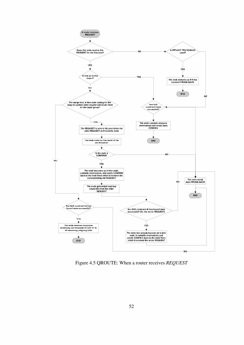
52
Figure 4.5 QROUTE: When a router receives REQUEST
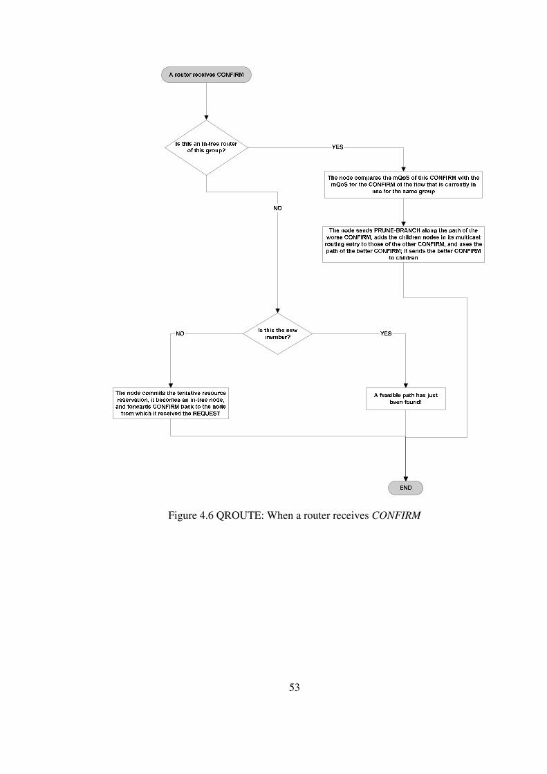
53
Figure 4.6 QROUTE: When a router receives CONFIRM
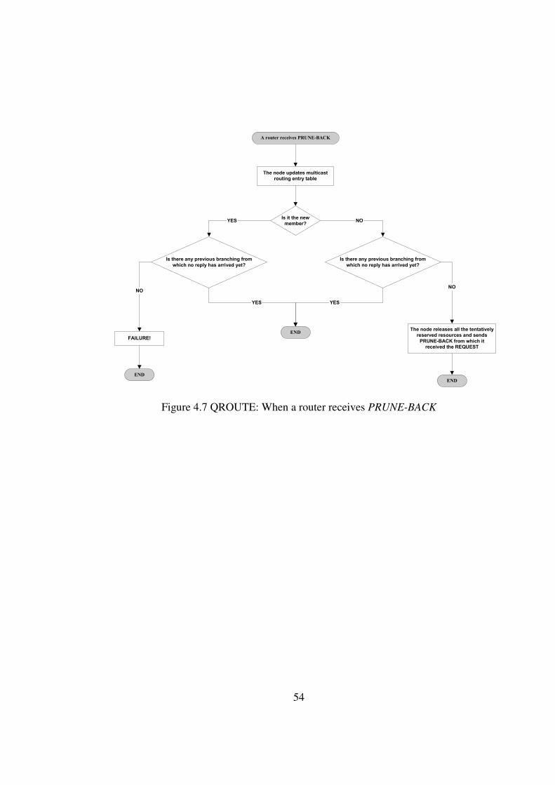
54
A router receives PRUNE-BACK
The node updates multicast
routing entry table
Is it the new
member?
Is there any previous branching from
which no reply has arrived yet?
Is there any previous branching from
which no reply has arrived yet?
YES NO
END
YES
FAILURE!
END
END
The node releases all the tentatively
reserved resources and sends
PRUNE-BACK from which it
received the REQUEST
NONO
YES
Figure 4.7 QROUTE: When a router receives PRUNE-BACK

55
An in-tree router receives
PRUNE-BRANCH
The in-tree router releases resources
reserved for that branch
Has this router (not “host”) become
a “leaf” of the tree now?
The router forwards PRUNE-BRANCH
upstream to its in-tree parent and
leaves the multicast tree
END
YES
NO
Figure 4.8 QROUTE: When a router receives PRUNE-BRANCH
4.1.2 Simulations
There are various simulations performed to test the performance of
QROUTE [38]. Two network types are used in those simulations. One of the
networks is the map of the major nodes of the MBone [3] network, as a
representative topology of actual multicast networks. In the MBone networks used
in the simulations, nodes with only one neighbour are eliminated, since they have
no effect on routing. The MBone networks have 32 nodes with an average degree
of 2.5. The other network model used in the simulations is the Waxman model
[41] with an average degree of 2.68.
56
The simulations are carried out both on a testbed and using OPNET [38].
The testbed used in simulations [38] consists of nodes each of which represents a
100 M-switched Ethernet subnet formed by a router, a switch, a client, and a
server. The interconnections between routers are 100 Mbps full-duplex point-to-
point links. There is exactly one server host in each subnet. The servers generate
data for multiple multicast sessions, and the clients represent all the end hosts in a
subnet. They are the clients who generate join/leave requests for all multicast
sessions. The arrival of end hosts to join a multicast group and the connection
duration of a client are modeled as exponential durations.
The considered QoS metrics are bandwidth (QoSB) and end-to-end delay
bound (QoSD). They are set to 5 Mbps and 20 msec, respectively, without any
reasoning described in the paper [38]. The hop bound, which is the time-to-live
field for the REQUEST packets, is taken as 15. For simplicity on the testbed, pre-
merging and implicit PRUNE-BACK are not implemented, and only a bandwidth
constraint (QoSB) of 250 kbps is considered. The same set of experiments is
repeated with the same network topology and set of system parameters in the
OPNET simulation.
QROUTE is simulated under different group densities [31]. Group density
is the ratio of the number of hosts in a multicast group to the total number of hosts
in the network. Since each node in the testbed is a subnet and a client may
represent multiple end hosts, the interarrival time of join requests for a client host
is set inversely proportional to the number of multicast groups that subnet has end
hosts in. That is to say, the frequency of join request generation depends on the
number of multicast end hosts represented by the clients in the subnet [38].
Some other QoS-based multicast routing protocols, namely SPR, YAM,
QoSMIC, QMRP, and S-QMRP, are compared with QROUTE under the same
network configurations [38]. The expanding rings [29] flooding technique is
implemented for YAM. It is assumed that QoSMIC performs local search and
multicast tree search in parallel. Actually, QMRP does not support additive QoS
constraints, but, for the simulations, QMRP is extended to support end-to-end
delay requirements. Both QMRP and S-QMRP are optimized by limiting the
57
branching degree [35,36] by five. For all these five protocols, an underlying
unicast routing protocol is assumed to exist to get the information on the shortest
path in terms of hops.
The performance metrics are connection setup latency, blocking
probability, routing overhead and efficiency of routing trees. Connection setup
latency is the duration between the generation of a join request and the
notification of the acceptance or rejection response. Blocking probability is the
ratio of rejected join requests. Routing overhead can be described as the average
number of control packets generated for each join request, i.e., the ratio of the
total number of control packets to the number of join requests. The important
point is that a control packet forwarded over a path of n hops brings an overhead
of n packets. Finally, routing tree efficiency is the average cost of the multicast
trees in terms of number of links used for different group densities [38].
For the results shown [38], the confidence interval is taken as 95% with a
decision gap of 5% for each data value.
4.1.3 Simulation Results
QROUTE outperforms all other protocols with respect to blocking
probability for all group densities [37,38]. SPR tries to construct a single path,
which is the unicast path from the new member to the root, and hence has the
smallest probability in meeting the QoS constraints. YAM and QoSMIC select the
in-tree nodes that are the closest ones to the new member and use typically the
shortest paths. Since they explore only a limited number of paths, they also have
high blocking probabilities. It is proved that QMRP finds a feasible branch if there
is one [35], but the selected branch may not be satisfactory for all of the QoS
requirements if there is more than one choice. QMRP tries the unicast path to the
root if possible, and ignores other more feasible paths. QMRP aims at connecting
a new member to a multicast tree at a point close to the root, and also it branches
out near the root instead of the new member. Hence, more and more links are
needed to connect to the multicast tree, network resources are used unnecessarily,

58
and finally consecutive join requests are denied. This behaviour becomes worse in
S-QMRP, because it searches for feasible branches starting from the root.
Feasible path search must be in the direction from the new member to the
multicast tree and it must begin near the new member to increase the chance of a
quick connection. As a result, the blocking caused by S-QMRP can be even
higher than those of YAM and QoSMIC. Furthermore, in each of the five
protocols, resource reservation is separated from routing process, and the final
connection attempt may fail due to lack of network resources that are thought to
be available according to the results of the searching stage. QROUTE takes a
simpler but more efficient approach from another point of view. It searches for all
the available feasible paths in parallel, uses a small number of links, and provides
a higher chance of constructing a feasible tree that uses network resources
efficiently [37,38].
As to comparing the routing overhead of the simulated protocols for
different group densities, SPR has the lowest routing overhead, as expected,
owing to its single-path routing behavior that causes high blocking. YAM has the
highest routing overhead for small group densities, because it floods the whole
network with protocol control packets to form a small tree. QoSMIC has the
highest overhead for large groups as a result of its multicast tree search performed
by the manager router [31]. The routing overheads generated by QROUTE,
QMRP and S-QMRP are close to each other, although QROUTE has lower
routing overhead than the other two most of the time. It is also shown that
QROUTE constructs its multicast trees with a smaller number of links than those
of QMRP and S-QMRP. Therefore, QROUTE uses less routing overhead to
construct more efficient multicast trees [38].
YAM, QoSMIC and S-QMRP use timeout to sense the result of feasible
path searching, and as a result, their connection setup durations are much longer
than the others. On the other hand, SPR, QMRP, and QROUTE do not use a
timeout mechanism. The connection setup latency of SPR is bounded by the
round-trip time for a request traveling to the root and a confirmation going from
the root back to the requester along the same unicast path. In QROUTE, the
59
connection setup latency is bounded by the round-trip time of the longest loop-
free path within the hop bound of the new member, along which a request has the
chance of reaching the tree. QMRP can result in a latency value as large as the
total delays of all links in both directions due to the branching out mechanism.
The small connection setup latency of QROUTE improves its responsiveness and
helps the protocol to avoid over-reservation [37,38].
QROUTE and all the other protocols are also compared on 50-node and
200-node Waxman networks with average degrees of 2.64 and 2.79, respectively
[38]. QROUTE gives the lowest blocking probability for all topologies, all
network sizes, and all group densities. Moreover, the blocking probability of
QROUTE remains almost unchanged as the network size increases. The
simulation results show that the routing overhead of QROUTE does not increase
too much as the network size is doubled. Hence, QROUTE is quite scalable with
network size in terms of routing overhead and blocking probability. QROUTE has
the smallest latency results, as expected from the above discussion. The latency of
QROUTE is limited and depends on the delay of the loop-free path from the new
member to the multicast tree (not necessarily the root). QROUTE avoids the large
overhead and latency of blind flooding [38]. Lastly, QROUTE constructs
multicast trees with smaller number of links than the other QoS protocols. This is
also an expected fact, since QROUTE does not perform blind flooding but
searches for a feasible path in order to connect to the existing tree from a point
close to the new member.
4.2 QMBF
4.2.1 Description
Many recent multicast applications desire quality of service (QoS) support
from their underlying networks, and, as a result of the increasing demand, many
QoS multicast routing protocols have been put forward. QMBF is a QoS-based
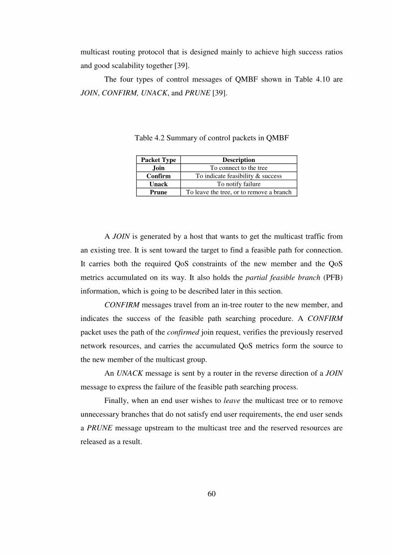
60
multicast routing protocol that is designed mainly to achieve high success ratios
and good scalability together [39].
The four types of control messages of QMBF shown in Table 4.10 are
JOIN, CONFIRM, UNACK, and PRUNE [39].
Table 4.2 Summary of control packets in QMBF
Packet Type Description
Join To connect to the tree Confirm To indicate feasibility & success Unack To notify failure Prune To leave the tree, or to remove a branch
A JOIN is generated by a host that wants to get the multicast traffic from
an existing tree. It is sent toward the target to find a feasible path for connection.
It carries both the required QoS constraints of the new member and the QoS
metrics accumulated on its way. It also holds the partial feasible branch (PFB)
information, which is going to be described later in this section.
CONFIRM messages travel from an in-tree router to the new member, and
indicates the success of the feasible path searching procedure. A CONFIRM
packet uses the path of the confirmed join request, verifies the previously reserved
network resources, and carries the accumulated QoS metrics form the source to
the new member of the multicast group.
An UNACK message is sent by a router in the reverse direction of a JOIN
message to express the failure of the feasible path searching process.
Finally, when an end user wishes to leave the multicast tree or to remove
unnecessary branches that do not satisfy end user requirements, the end user sends
a PRUNE message upstream to the multicast tree and the reserved resources are
released as a result.

61
QMBF uses M-hop bounded flooding technique to provide both scalability
and high success ratio [39]. As the name implies, this technique involves flooding
only a subset of the whole network with control packets. Each node sends
bounded flooding messages through all of its neighbours along a path of M nodes.
The last node for a bounded flooding packet is called an edge node, the area in
which bounded flooding messages travel before they die is called the local
network cell (LNC), and the lifetime of a bounded flooding packet determines the
LNC radius. With the help of the bounded flooding messages, each node gets the
knowledge of link conditions in its LNC, all nodes in the LNC, and their distances
from the root. Those bounded flooding messages can be exchanged either
periodically or when changes in QoS and reachability conditions exceed a specific
threshold value [39].
When a host wishes to join a multicast group, it decides on one or more
edge nodes of the LNC whose center is the host itself, and it forwards one or more
JOIN messages accordingly. The nodes between the center of a LNC and edges of
the same LNC are said to be intermediate nodes, and they are responsible only for
carrying the packet from the center to the edges along a predetermined path. If an
in-tree router receives a JOIN message, and if it is not the source of the group, it
performs a QoS test on the incoming packet and sends back a CONFIRM or
UNACK according to the result of the test. Otherwise, if it is the root, this means
that the REQUEST traversed the network from the new member to the root
successfully, and the root sends a CONFIRM downstream to the new member
[39].
If a node that receives a REQUEST is an intermediate router, then it
simply forwards the packet toward the selected edge router. When the packet
comes to an edge router, the edge node checks its LNC information and selects
the edge nodes with the shortest paths to the root, if such edges exist. Obviously,
the paths should not be backward to this LNC, since a REQUEST should never be
sent in the direction from the root to the new host along the path it has just
traveled. Then, the edge node tries to locate feasible paths from itself to its edges,

62
and it forwards the REQUEST along those feasible paths to the selected edges
[39].
If an edge node that receives a REQUEST cannot find feasible paths to any
of its edges with the shortest paths, that edge router passes to the second state of
the partial feasible search procedure. All in all, the join request does not have to
be sent along the shortest path, as long as the QoS constraints are completely
satisfied [39]. The second state is an emergency state, and the edge router now
tries to find feasible paths to all of its edges. If it can locate feasible paths this
time, then join requests are successfully forwarded along the discovered paths.
Otherwise, the result is a fatal failure, and the edge rejects the REQUEST by
sending back an UNACK.
On the other hand, when a CONFIRM arrives at a node, the node checks
its multicast routing table. If there is an entry in the table for an existing QoS
traffic flow whose QoS support is better than the QoS constraints satisfied by the
incoming CONFIRM, then the router sends PRUNE upstream along the path
followed by the CONFIRM, cancels all reservations on that path, and adds the
children for whom the pruned CONFIRM was intended to the children list of the
better traffic flow [39]. If there is no better routing entry in the table, then the
CONFIRM is sent to the related children nodes. The existing confirmed entries are
again checked against this new confirmation message, and the children of the
multicast routing entries of worse entries are added to this flow by pruning their
current parents.
The feasible path searching process is said to be successful if at least one
CONFIRM comes from an in-tree router to the new host. On the other hand, when
a node fails to forward JOIN messages toward the root, then the node sends
PRUNE-BACK in the backward direction. When the new host fails to find a
feasible path to reach the multicast tree with JOIN messages, or when it receives
PRUNE-BACK packets from all JOIN paths, the feasible path search ends with a
failure [39].
Figures 4.9, 4.10, and 4.11 explain QMBF operations upon the receipt of a
JOIN, CONFIRM, and UNACK.

63
During the feasible path searching phase, when a node forwards a JOIN
message, it also reserves resources along the partial feasible path in the LNC it
belongs to. Hence, the required resources are kept for this QoS application and are
not given to another [39]. As a result, QMBF can be classified as a QoS-
guaranteed multicast routing protocol, just like QROUTE.
In contrast to its former, the QMRP protocol, QMBF is designed to
support multiple QoS requirements; that is, constraints may be additive (delay,
jitter), nonadditive (bandwidth), or multiplicative (loss), or a combination of these
types [39]. This brings generality to QMBF.
The bounded flooding technique and LNC usage in QMBF aims at
maintaining scalability, reducing routing packet overhead, and shortening tree
setup latency while keeping success ratio values high [39]. Designed for Internet
multicast, QMBF keeps in mind that the number of nodes in the Internet may be
so huge, and visiting all nodes before reaching a multicast source may lead to an
inefficient resource usage and high latency. By dividing a whole network into
smaller LNCs, QMBF intends to make more careful and precise decisions in a
quicker way so as to lower the tree establishment delay and to increase success
ratio.
In all of the figures given in this chapter, mQoS, rQoS, and aQoS stand for
the total QoS between the source and the specified router, required QoS
constraint, and accumulated QoS, respectively. M.in is the set of incoming
interfaces for multicast routing, and M.out represents the set of outgoing
interfaces. Here, it should be noted that the incoming (outgoing) interfaces for
multicast routing are the outgoing (incoming) interfaces for the feasible path
search process. M.state shows which of the three states a QMBF node is in. State
0 is for an intermediate router, state 1 is sending JOIN messages to least-cost
edges, and state 2 is the last state of sending JOINs to edges. M.num shows the
number of JOIN messages sent, and M.fix is an internal field of a QMBF router to
display reservation confirmation.
Finally, optimization methods [35,39] may be proposed for the QMBF
mechanism to minimize the overhead more and more. The optimization method

64
for a node that receives a join request can be selecting only the edge node that is
closest to the least-cost path from the current node to the multicast source. In
addition, the number of nodes between a new host and the multicast source
branching out to neighbours can be limited. Similarly, the number of nodes a node
can branch out to can also be limited to remove unnecessary packet overhead.
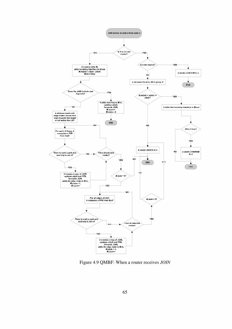
65
Figure 4.9 QMBF: When a router receives JOIN
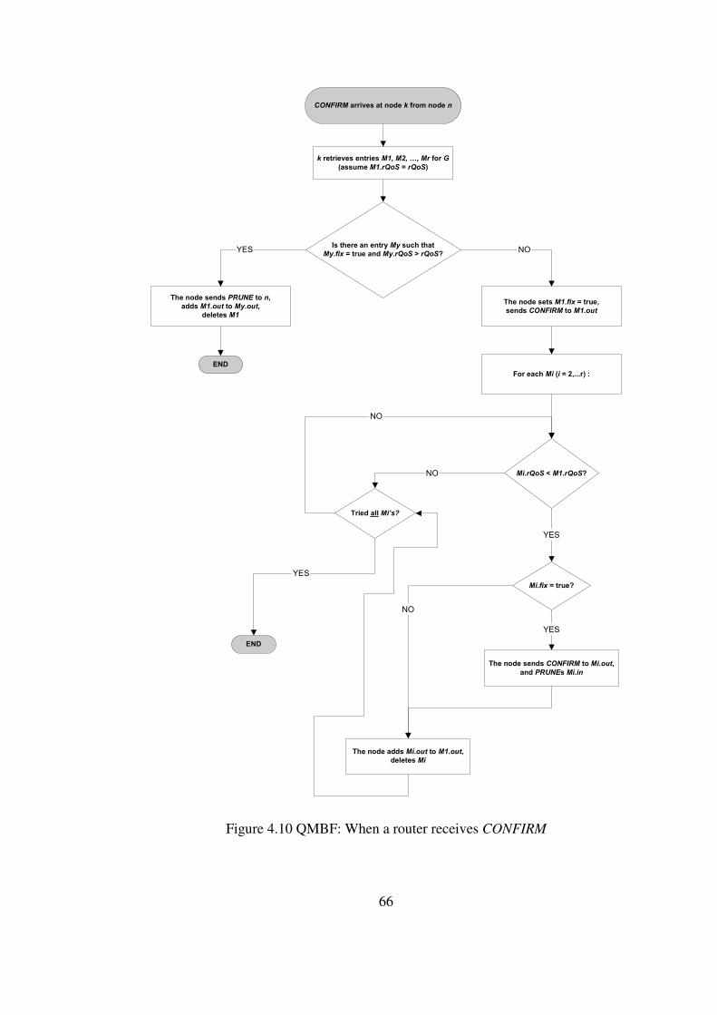
66
CONFIRM arrives at node k from node n
Is there an entry My such that
My.fix = true and My.rQoS > rQoS?
k retrieves entries M1, M2, …, Mr for G
(assume M1.rQoS = rQoS)
END
The node adds Mi.out to M1.out,
deletes Mi
The node sends PRUNE to n,
adds M1.out to My.out,
deletes M1
The node sets M1.fix = true,
sends CONFIRM to M1.out
For each Mi (i = 2,...r) :
Mi.fix = true?
Tried all Mi’s?
Mi.rQoS < M1.rQoS?
END
The node sends CONFIRM to Mi.out,
and PRUNEs Mi.in
YES NO
NO
YES
YES
NO
YES
NO
Figure 4.10 QMBF: When a router receives CONFIRM

67
Figure 4.11 QMBF: When a router receives UNACK

68
4.2.2 Simulations
QMBF is compared with QMRP [35], Spanning Joins [29], and ordinary
SPR by using simulations performed on NS-2 [50]. The network topologies used
in simulations are widely used Waxman [41] topologies having 100 nodes on a
100-by-100 grid, and the average degree of nodes is between 4 and 5. Two tree
sizes of 10 and 40 are used in simulations, but the tree size is the number of total
nodes a multicast tree covers, including both the intermediate nodes and the end
nodes. So, tree size is different than group size [39]. It is assumed that there can
be only one multicast session in the network at a given time.
In each simulation, a random Waxman network topology is created, a
multicast tree is generated, and a node out of the tree is randomly selected. The
new member has randomly generated QoS requirements each time, and the QoS
state of each link is also randomly generated. Hence, the condition that a link can
meet the new member’s QoS requirements or not depends on a random
probability, and link success ratio is defined as the ratio of links that satisfy the
new member’s QoS requirements. For each situation consisting of different
protocols, different group sizes, and different link success ratios, the simulation is
performed 200 times. The work mainly focuses on the success ratio, which is
defined as the ratio of the number of successful search attempts to the total
number of trials [39].
4.2.3 Simulation Results
According to the results given in the related work [39], QMBF and QMRP
have comparable success ratio tendencies, and QMBF outperforms QMRP by
increasing optimization bounds. The increase in the success ratio of QMBF with
increasing hop bound is an expected result, since the higher hop bound becomes,
the more extensive path search is. Compared with other protocols, QMBF
provides more successful search attempts than those of QMRP, Spanning Joins,
and SPR. When a link on the path of a join request fails to satisfy the QoS

69
requirements of a new member, SPR and Spanning Joins fail, and QMRP enters
its multipath search mode. The bounded flooding approach and LNC usage in
QMBF helps to decide on forwarding paths more accurately than QMRP [39].

70
CHAPTER 5
SIMULATION WORK
For performance evaluation and comparison, two recent QoS multicast
routing protocols are simulated in Network Simulator-2 (ns-2) [50]. Different
random Waxman topologies are generated, and the protocols are tested under
various network conditions and end user requirements.
In this section, the reasoning behind the selected routing protocols and test
platforms, performance metrics used in the simulations, details of the
experiments, and results of the experiments are presented.
5.1 The Selected Protocols and The Simulation Environment
In the simulations two recent QoS multicast routing protocols that have
not been compared with each other, namely QROUTE [38] and QMBF [39], are
tested. Both of the two protocols classify themselves as QoS-guaranteed
protocols. Also, none of the two protocols has been compared to another protocol
that uses a different approach, and this is another motivation for their comparison.
QROUTE and QMBF are implemented in ns-2 that is a widely accepted
and used tool, providing support for the simulation of TCP, routing, and multicast
protocols over wired or wireless networks.
The protocols are simulated in ns-2 on randomly created Waxman
topologies [41] due to performance comparison advantages. Firstly, Waxman
topology is richer in terms of alternative paths, while the MBone has limited
routing choices. Measurements of the Internet topology suggest that the network
is becoming denser and richer in routes [34]. Secondly, the aim of this study is to
gain an insight into the actual relative performances of the protocols, and the aim

71
is covering a variety of random topologies, instead of predicting the topology.
Hence, Waxman topologies provide the sufficient test circumstances for the
performance comparison of routing algorithms using realistic approaches and
parameters such as geographical distance, router degrees, and distribution of QoS
metrics.
The topologies are generated using a topology generator tool, BRITE [52]
that improved the state-of-the-art topology generation techniques and reflects
many aspects of the actual Internet topology, like hierarchical structure and degree
distribution. BRITE combines the strengths of many generation models, and
provides interfaces to widely used simulation and visualization applications such
as ns, SSF, and OmNet++.
In this study, 50- and 100-node random Waxman topologies are generated
by BRITE on a 100-by-100 grid, and the average degree of nodes is 4 for each
topology. Nodes with only one neighbour are eliminated, since they have no effect
on routing and BRITE output turns into a tree-like topology when the minimum
degree is taken as 1, as shown in Figure 5.1. Hence, the graphs are chosen to be
non-planar with a minimum degree of 2. Sample topologies are shown in Figures
5.2 and 5.3. Link delay distribution is based on the geographical distance between
nodes [41], and bandwidth is uniformly distributed between 10 Mbps and 1024
Mbps.
The objective of the simulation study is to compare the performances of
routing algorithms for QoS Internet multicast applications. Therefore, no
background traffic or loss rate assignment is necessary, and no error control, flow
control, or reliability aspects are considered.

72
Figure 5.1 Sample 50-node BRITE topology with a minimum degree of one
Figure 5.2 Sample 50-node BRITE topology with a minimum degree of two
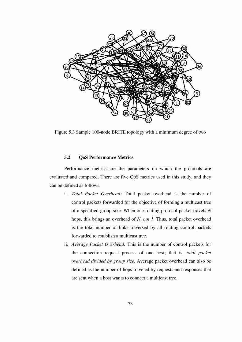
73
Figure 5.3 Sample 100-node BRITE topology with a minimum degree of two
5.2 QoS Performance Metrics Performance metrics are the parameters on which the protocols are
evaluated and compared. There are five QoS metrics used in this study, and they
can be defined as follows:
i. Total Packet Overhead: Total packet overhead is the number of
control packets forwarded for the objective of forming a multicast tree
of a specified group size. When one routing protocol packet travels N
hops, this brings an overhead of N, not 1. Thus, total packet overhead
is the total number of links traversed by all routing control packets
forwarded to establish a multicast tree.
ii. Average Packet Overhead: This is the number of control packets for
the connection request process of one host; that is, total packet
overhead divided by group size. Average packet overhead can also be
defined as the number of hops traveled by requests and responses that
are sent when a host wants to connect a multicast tree.

74
iii. Success Ratio: Success ratio is defined as the ratio of the successful
connection attempts to the targeted group size.
iv. Tree (Total) Setup Latency: Time between the generation of the first
join request message and the end of the last connection attempt for a
number of hosts that wish to form a multicast group.
v. Connection (Average) Setup Latency: This is the duration between the
forwarding of a join request by a host and the arrival of the response to
the host.
These performance metrics are tested under varying group densities and
QoS requirements. Group density is the ratio of the desired group size of a
multicast session to the total number of nodes in the network. In the simulations,
group density takes the values 10%, 30%, 50%, 70%, 90%, and 100%.
An example of how test results are interpreted in this study can be as
follows. If we assume that there are 50 nodes in the network, and the group
density is 30%, then the targeted group size is 15. As another assumption, at the
end of the experiments, the results 600 packets, 40%, and 120 msec are found for
total packet overhead, success ratio, and tree setup latency, respectively. The
comment on these results should be as follows: first, a multicast group of 15
nodes out of 50 nodes can be formed with a probability of 40% using 600 packets
in 120 msec. In that case, the average packet overhead is 40 for each entering host
(found by dividing 600 packets by 15), and the time required for the processing of
each single request, that is the average setup latency, is 8 msec (calculated by the
division of 120 msec by 15).
5.3 Experiments
Experiments are designed with one-to-many multicast idea [15,16]. There
is a single source and possibly multiple receivers in a group. In the experiments, a
random source and randomly selected nodes are connected to form a group.
Simulation scenarios, reasoning for the used constraints, and test
conditions such as number of multicast sessions, session handling, unused
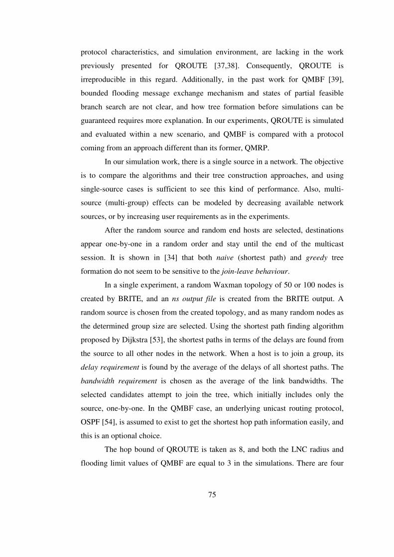
75
protocol characteristics, and simulation environment, are lacking in the work
previously presented for QROUTE [37,38]. Consequently, QROUTE is
irreproducible in this regard. Additionally, in the past work for QMBF [39],
bounded flooding message exchange mechanism and states of partial feasible
branch search are not clear, and how tree formation before simulations can be
guaranteed requires more explanation. In our experiments, QROUTE is simulated
and evaluated within a new scenario, and QMBF is compared with a protocol
coming from an approach different than its former, QMRP.
In our simulation work, there is a single source in a network. The objective
is to compare the algorithms and their tree construction approaches, and using
single-source cases is sufficient to see this kind of performance. Also, multi-
source (multi-group) effects can be modeled by decreasing available network
sources, or by increasing user requirements as in the experiments.
After the random source and random end hosts are selected, destinations
appear one-by-one in a random order and stay until the end of the multicast
session. It is shown in [34] that both naive (shortest path) and greedy tree
formation do not seem to be sensitive to the join-leave behaviour.
In a single experiment, a random Waxman topology of 50 or 100 nodes is
created by BRITE, and an ns output file is created from the BRITE output. A
random source is chosen from the created topology, and as many random nodes as
the determined group size are selected. Using the shortest path finding algorithm
proposed by Dijkstra [53], the shortest paths in terms of the delays are found from
the source to all other nodes in the network. When a host is to join a group, its
delay requirement is found by the average of the delays of all shortest paths. The
bandwidth requirement is chosen as the average of the link bandwidths. The
selected candidates attempt to join the tree, which initially includes only the
source, one-by-one. In the QMBF case, an underlying unicast routing protocol,
OSPF [54], is assumed to exist to get the shortest hop path information easily, and
this is an optional choice.
The hop bound of QROUTE is taken as 8, and both the LNC radius and
flooding limit values of QMBF are equal to 3 in the simulations. There are four

76
conditions on which the simulations are performed, determined by the topology
and constraints. The topology may have 50 or 100 nodes, and the user
requirements may be tight or loose. Loose constraints differ from tight ones in
such a way that, the average of the delays on the shortest delay paths from the
source to all others is multiplied by 1.5, and the average bandwidth is divided by
1.5 to relax the user requirements.
The confidence interval used in the experiments is either 90% or 80%,
with a gap of 0.1 or 0.2, respectively. The confidence interval determination
depends on the execution time of the experiments. For the 50-node networks, the
confidence interval is 90% with a gap of 0.1. For the 100-node topologies, a
confidence interval of 80% and a gap of 0.2 can be satisfactory to compare the
protocols.
5.4 Simulation Results
The quantitative results obtained from experiments are presented in
Figures 5.4 – 5.23.
It can be seen in Figures 5.4 – 5.7 that, since QROUTE performs flooding
at every node, its overhead is larger than that of QMBF in every instance. This
also causes the overhead of QROUTE to increase more rapidly. When the QoS
requirements are relaxed, the chance of a join request to find a feasible path
increases, and request packets traverse more links. More requests mean more
responses, and hence, the total overhead increases. Also, when the network size is
doubled, hop distances between nodes become higher, and control packets have to
travel more in the network, increasing the overhead.
As seen in Figures 5.8 – 5.11, due to the large difference between “total”
overhead values, again QROUTE ends up with larger “average” overhead
measurements. But now, the trend of the average overhead curve is the opposite
of that of the total overhead curve. Total overhead increases with group density;
but, as the group density increases, more routers in the network become involved
in the tree formation process, and a request packet gets its response without

77
flooding a large network region. Therefore, overhead decreases on the average.
Since the total overhead of QMBF does not grow as fast as the total overhead of
QROUTE, its average overhead quantities are very close to each other, and the
minor decrease is quite indistinguishable.
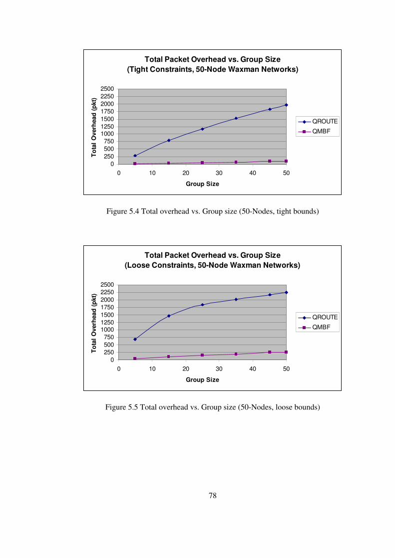
78
Total Packet Overhead vs. Group Size
(Tight Constraints, 50-Node Waxman Networks)
0
250
500
750
1000
1250
1500
1750
2000
2250
2500
0 10 20 30 40 50
Group Size
To
tal
Overh
ead
(p
kt)
QROUTE
QMBF
Figure 5.4 Total overhead vs. Group size (50-Nodes, tight bounds)
Total Packet Overhead vs. Group Size
(Loose Constraints, 50-Node Waxman Networks)
0
250
500
750
1000
1250
1500
1750
2000
2250
2500
0 10 20 30 40 50
Group Size
To
tal
Overh
ead
(p
kt)
QROUTE
QMBF
Figure 5.5 Total overhead vs. Group size (50-Nodes, loose bounds)

79
Total Packet Overhead vs. Group Size
(Tight Constraints, 100-Node Waxman Networks)
0
750
1500
2250
3000
3750
4500
5250
6000
6750
0 20 40 60 80 100
Group Size
To
tal
Overh
ead
(p
kt)
QROUTE
QMBF
Figure 5.6 Total overhead vs. Group size (100-Nodes, tight bounds)
Total Packet Overhead vs. Group Size
(Loose Constraints, 100-Node Waxman Networks)
0
750
1500
2250
3000
3750
4500
5250
6000
6750
0 20 40 60 80 100
Group Size
To
tal
Overh
ead
(p
kt)
QROUTE
QMBF
Figure 5.7 Total overhead vs. Group size (100-Nodes, loose bounds)

80
Average Packet Overhead vs. Group Size
(Tight Constraints, 50-Node Waxman Networks)
0
25
50
75
100
125
150
0 10 20 30 40 50
Group Size
Avera
ge O
verh
ead
(p
kt)
QROUTE
QMBF
Figure 5.8 Average overhead vs. Group size (50-Nodes, tight bounds)
Average Packet Overhead vs. Group Size
(Loose Constraints, 50-Node Waxman Networks)
0
25
50
75
100
125
150
0 10 20 30 40 50
Group Size
Avera
ge O
verh
ead
(p
kt)
QROUTE
QMBF
Figure 5.9 Average overhead vs. Group size (50-Nodes, loose bounds)

81
Average Packet Overhead vs. Group Size
(Tight Constraints, 100-Node Waxman Networks)
0
25
50
75
100
125
150
175
200
225
250
0 20 40 60 80 100
Group Size
Avera
ge O
verh
ead
(p
kt)
QROUTE
QMBF
Figure 5.10 Average overhead vs. Group size (100-Nodes, tight bounds)
Average Packet Overhead vs. Group Size
(Loose Constraints, 100-Node Waxman Networks)
0
25
50
75
100
125
150
175
200
225
250
0 20 40 60 80 100
Group Size
Avera
ge O
verh
ead
(p
kt)
QROUTE
QMBF
Figure 5.11 Average overhead vs. Group size (100-Nodes, loose bounds)
82
Success Ratio vs. Group Size
(Tight Constraints, 50-Node Waxman Networks)
0
10
20
30
40
50
60
70
80
90
100
0 10 20 30 40 50
Group Size
Su
ccess R
ati
o (
%)
QROUTE
QMBF
Figure 5.12 Success ratio vs. Group size (50-Nodes, tight bounds)
Success Ratio vs. Group Size
(Loose Constraints, 50-Node Waxman Networks)
0
10
20
30
40
50
60
70
80
90
100
0 10 20 30 40 50
Group Size
Su
ccess R
ati
o (
%)
QROUTE
QMBF
Figure 5.13 Success ratio vs. Group size (50-Nodes, loose bounds)

83
Success Ratio vs. Group Size
(Tight Constraints, 100-Node Waxman Networks)
0
10
20
30
40
50
60
70
80
90
100
0 20 40 60 80 100
Group Size
Su
ccess R
ati
o (
%)
QROUTE
QMBF
Figure 5.14 Success ratio vs. Group size (100-Nodes, tight bounds)
Success Ratio vs. Group Size
(Loose Constraints, 100-Node Waxman Networks)
0
10
20
30
40
50
60
70
80
90
100
0 20 40 60 80 100
Group Size
Su
ccess R
ati
o (
%)
QROUTE
QMBF
Figure 5.15 Success ratio vs. Group size (100-Nodes, loose bounds)
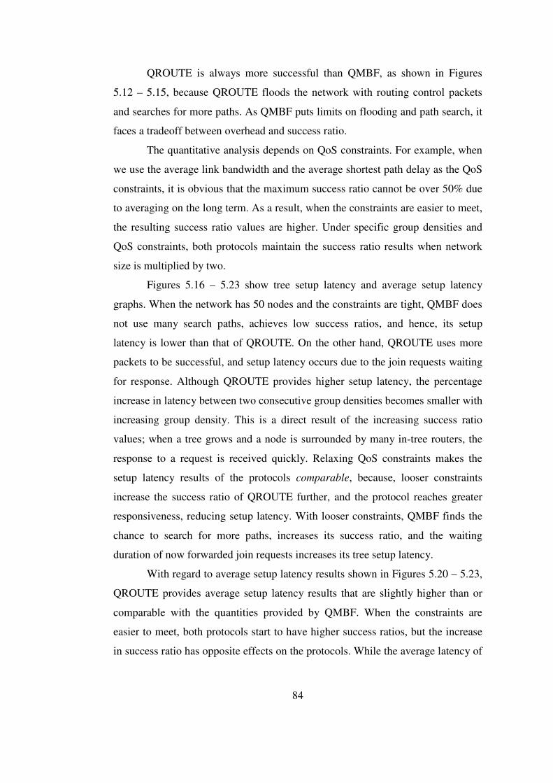
84
QROUTE is always more successful than QMBF, as shown in Figures
5.12 – 5.15, because QROUTE floods the network with routing control packets
and searches for more paths. As QMBF puts limits on flooding and path search, it
faces a tradeoff between overhead and success ratio.
The quantitative analysis depends on QoS constraints. For example, when
we use the average link bandwidth and the average shortest path delay as the QoS
constraints, it is obvious that the maximum success ratio cannot be over 50% due
to averaging on the long term. As a result, when the constraints are easier to meet,
the resulting success ratio values are higher. Under specific group densities and
QoS constraints, both protocols maintain the success ratio results when network
size is multiplied by two.
Figures 5.16 – 5.23 show tree setup latency and average setup latency
graphs. When the network has 50 nodes and the constraints are tight, QMBF does
not use many search paths, achieves low success ratios, and hence, its setup
latency is lower than that of QROUTE. On the other hand, QROUTE uses more
packets to be successful, and setup latency occurs due to the join requests waiting
for response. Although QROUTE provides higher setup latency, the percentage
increase in latency between two consecutive group densities becomes smaller with
increasing group density. This is a direct result of the increasing success ratio
values; when a tree grows and a node is surrounded by many in-tree routers, the
response to a request is received quickly. Relaxing QoS constraints makes the
setup latency results of the protocols comparable, because, looser constraints
increase the success ratio of QROUTE further, and the protocol reaches greater
responsiveness, reducing setup latency. With looser constraints, QMBF finds the
chance to search for more paths, increases its success ratio, and the waiting
duration of now forwarded join requests increases its tree setup latency.
With regard to average setup latency results shown in Figures 5.20 – 5.23,
QROUTE provides average setup latency results that are slightly higher than or
comparable with the quantities provided by QMBF. When the constraints are
easier to meet, both protocols start to have higher success ratios, but the increase
in success ratio has opposite effects on the protocols. While the average latency of

85
QROUTE decreases due to the simplicity of reaching a tree, the average latency
of QMBF increases as the protocol begins to search a wider region with looser
constraints. Finally, average setup latency goes down for both protocols with
higher group densities owing to the easiness of meeting the tree as a result of
better success ratio.
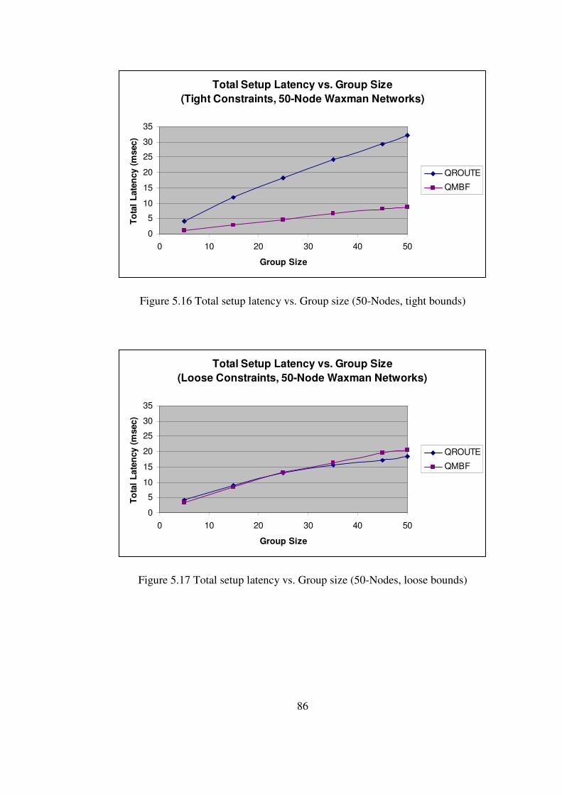
86
Total Setup Latency vs. Group Size
(Tight Constraints, 50-Node Waxman Networks)
0
5
10
15
20
25
30
35
0 10 20 30 40 50
Group Size
To
tal
Late
ncy (
msec)
QROUTE
QMBF
Figure 5.16 Total setup latency vs. Group size (50-Nodes, tight bounds)
Total Setup Latency vs. Group Size
(Loose Constraints, 50-Node Waxman Networks)
0
5
10
15
20
25
30
35
0 10 20 30 40 50
Group Size
To
tal
Late
ncy (
msec)
QROUTE
QMBF
Figure 5.17 Total setup latency vs. Group size (50-Nodes, loose bounds)

87
Total Setup Latency vs. Group Size
(Tight Constraints, 100-Node Waxman Networks)
0
10
20
30
40
50
60
70
0 20 40 60 80 100
Group Size
To
tal
Late
ncy (
msec)
QROUTE
QMBF
Figure 5.18 Total setup latency vs. Group size (100-Nodes, tight bounds)
Total Setup Latency vs. Group Size
(Loose Constraints, 100-Node Waxman Networks)
0
10
20
30
40
50
60
70
0 20 40 60 80 100
Group Size
To
tal
Late
ncy (
msec)
QROUTE
QMBF
Figure 5.19 Total setup latency vs. Group size (100-Nodes, loose bounds)

88
Average Setup Latency vs. Group Size
(Tight Constraints, 50-Node Waxman Networks)
0
0,1
0,2
0,3
0,4
0,5
0,6
0,7
0,8
0,9
1
0 10 20 30 40 50
Group Size
Avera
ge L
ate
ncy (
msec)
QROUTE
QMBF
Figure 5.20 Average setup latency vs. Group size (50-Nodes, tight bounds)
Average Setup Latency vs. Group Size
(Loose Constraints, 50-Node Waxman Networks)
0
0,1
0,2
0,3
0,4
0,5
0,6
0,7
0,8
0,9
1
0 10 20 30 40 50
Group Size
Avera
ge L
ate
ncy (
msec)
QROUTE
QMBF
Figure 5.21 Average setup latency vs. Group size (50-Nodes, loose bounds)

89
Average Setup Latency vs. Group Size
(Tight Constraints, 100-Node Waxman Networks)
0
0,1
0,2
0,3
0,4
0,5
0,6
0,7
0,8
0,9
1
0 20 40 60 80 100
Group Size
Avera
ge L
ate
ncy (
msec)
QROUTE
QMBF
Figure 5.22 Average setup latency vs. Group size (100-Nodes, tight bounds)
Average Setup Latency vs. Group Size
(Loose Constraints, 100-Node Waxman Networks)
0
0,1
0,2
0,3
0,4
0,5
0,6
0,7
0,8
0,9
1
0 20 40 60 80 100
Group Size
Avera
ge L
ate
ncy (
msec)
QROUTE
QMBF
Figure 5.23 Average setup latency vs. Group size (100-Nodes, loose bounds)

90
Considering average overhead, success ratio, and setup latency, both
protocols keep their performance trends while switching from 50-node networks
to 100-node networks. This can be seen as a sign of scalability. Still, to prove that
the protocols are really scalable, various other network sizes should be analyzed,
but this analysis is not included in this thesis, since scalability issue is out of the
scope of this work.
QROUTE turns out to perform better than QMBF, regarding the
simulation results. Having a higher success ratio is obviously a plus. Furthermore,
the higher overhead and latency values of QROUTE cannot be viewed as
unacceptable. First, the latency of QROUTE is nearly four times the latency of
QMBF, but still in that case, the latency is only around 30 msec when attempting
to reach a group density of 100% with tight constraints. Second, with looser
constraints or larger networks, QMBF starts to provide comparably high latencies.
As regards the overhead, the number of packets of size smaller than 100 bytes
forwarded in the network cannot be regarded as large for the Internet [51] or for a
multicast backbone.

91
CHAPTER 6
CONCLUSION Many currently developing applications involve one-to-many
communications, and, therefore, multicast is crucial due to its ability of delivering
point- or multipoint-to-multipoint data in an efficient and scalable way. The novel
applications start to have emerging user requirements, and satisfying the
requirements addresses the problem of QoS multicast routing protocol design to
manage network resources.
The fact that traditional multicast routing protocols consider only best-
effort traffic creates the need for quality of service (QoS) multicast routing
protocols, and several ideas have been proposed in this field.
The proposed ideas can be divided into three main classes, namely QoS-
aware, QoS-sensitive, and QoS-guaranteed routing protocols. The categories
differ in their resource reservation methods and feasible path searching directions.
QoS-sensitive and QoS-aware routing protocols establish routing paths with the
resources reserved by an additional reservation protocol after the search phase.
However, any change in the availability of resources causes the final connection
to fail, and to solve this problem together with the over-reservation challenge,
QoS-guaranteed routing protocols are designed. QoS-guaranteed multicast routing
protocols must be able to maintain network resources for the QoS applications,
must avoid overuse of resources, and they must be immune to dynamic changes in
network conditions.
QGMRP, QMRP, and S-QMRP are the examples to the QoS-aware
multicast routing protocols. QoSMIC is one of the most famous QoS-sensitive
multicast routing protocols. Finally, QROUTE and QMBF are two current QoS-

92
guaranteed multicast routing protocols that are analyzed and compared in this
study.
The comparative performance evaluation study of QROUTE and QMBF is
carried out using the network simulator ns-2, on Waxman topologies created by
the topology generator BRITE. The protocols are tested with different user
requirements. The performance evaluation is based on control packet overhead,
success ratio, and setup latency. These performance metrics are measured on
different random Waxman topologies with varying multicast group sizes and QoS
constraints.
The results show that flooding at every node brings a higher overhead to
QROUTE than that of QMBF, and the total packet overhead of QROUTE
increases more rapidly. When the QoS requirements are relaxed, links become
more feasible, and the chance of a join request to find an appropriate path
increases. As a result of this, request packets travel along more links in the
network. The increasing number of requests in the network means getting more
responses. Since the total packet overhead is measured as the sum of all routing
protocol packets forwarded in the network, the total overhead increases. If the
network size is doubled, number of hops between an end host and the multicast
source is likely to grow, and again control packets have to traverse more links in
the network. Hence, loosening the QoS constraints or enlarging the
communication network results in a more extensive path search and higher total
packet overhead.
Similar to the differences between total overhead values of the two
protocols, QROUTE ends up with larger average overhead measurements.
Contrary to the total packet overhead results, the average overhead results have a
tendency to decrease with group size for both protocols. As the group density
increases, more routers take part in the tree construction, and a request packet
does not have to flood a large network region this time. Therefore, overhead
decreases on the average. From another point of view, the average overhead can
be seen as the derivative of the total packet overhead with respect to group
density. Since the growth rate of the total overhead becomes smaller with larger

93
multicast groups, the average overhead appears to be a non-increasing function of
group density for both protocols.
QROUTE is always more successful in finding feasible paths than QMBF,
because QROUTE floods the network with routing control packets and searches
for more paths. The constraints of QMBF on flooding hops and path search causes
the protocol to have very small overhead and latency values in return for low
success ratio results. The success ratio of QMBF seems to be dependent only on
network size and QoS constraints, but not on group size. The success ratio stays
more or less the same with different group densities under specific conditions, and
it changes only when the chance of finding a feasible path increases with lower
constraints or when the network size offers more probabilities to the join request.
The quantitative analysis results are also determined by the QoS
constraints of end users wishing to join the multicast tree in consideration. If the
QoS requirements are harder to be satisfied, it is more probable that join requests
begin to fail, and the maximum success ratio that can be reached goes down. This
is a statistical result; if an experiment is repeated for a sufficiently long time with
the same requirement generation approach, the long-term results are directly
determined by the QoS constraint generation mechanism used in the experiments.
With smaller network sizes, or with tighter user constraints, QMBF does
not search for many routing paths, stays at low success ratios, and hence, it has
lower resulting setup latency than the setup latency of QROUTE. On the other
hand, QROUTE makes control packets visit more nodes to be more successful,
and this method increases setup latency as a result of longer waiting durations for
more responses to forwarded join requests. As a result of the increasing success
ratio values, a node becomes surrounded by many in-tree routers for large group
densities. The response to a request is received more quickly when group density
becomes higher, and although QROUTE provides high setup latency, the
percentage increase in latency between two consecutive group densities becomes
smaller with increasing group density. Relaxing QoS constraints generated by the
new hosts makes the setup latency results of the two protocols comparable,
because, the high success ratio of QROUTE increases even more, and the setup

94
latency is reduced by increased responsiveness. In the case of loose QoS
requirements, QMBF finds out that the network paths are worth trying, and it
starts an extended search. A thorough search increases the success ratio, and
having to wait for the answers to the requests forwarded along the search paths
increases the tree setup latency.
As in the case of average control packet overhead calculation, average
setup latency can be thought of as the derivative of total setup latency with respect
to group size. Total tree setup latency is the total time passed between the
forwarding of the first join request packet by an end host and the receipt of the
response by the same host. The response may be positive or negative; that is to
say, if a confirmation response comes to the requester, then the setup latency is
determined by the arrival of the confirmation. Otherwise, the host goes on to wait
until a confirmation arrives or all requests are rejected. The average setup latency
of QROUTE is comparable with or slightly higher than the average latency of
QMBF. If the QoS constraints are easy to meet, both protocols tend to have higher
success ratios than the results in the “tight constraints” case, but the increase in
success ratio has opposite effects on these protocols. The average latency of
QROUTE decreases when it is easier to reach an existing multicast tree. On the
other hand, the average latency of QMBF increases as the protocol begins to
search a wider region, looking for a feasible path to connect a new host to the
multicast tree. The two protocols begin to meet at a common middle point under
lower expectations from the network. Average setup latency goes down for both
protocols with larger group densities, as a result of increasing success ratio and
getting closer to the multicast tree.
The simulation results show that QROUTE outperforms QMBF, and
QMBF does not come up to expectations. Not only has QROUTE a higher success
ratio, but also the larger overhead and latency values of QROUTE are quite
appropriate for the Internet and for the MBone networks. The 30 msec latency of
QROUTE to reach a group density of 100%, or the number of small-size control
packets QROUTE uses to construct its multicast tree cannot be said to be too high
for a large interconnection network. Furthermore, decreasing setup latency or
95
using a small number of packets has no meaning unless a reasonably high success
ratio is achieved.
According to the average overhead, success ratio, and setup latency
results, both protocols show similar performance trends while switching from 50-
node networks to 100-node networks. This result can be regarded as a sign of
scalability, but, to prove the scalability of the two protocols, various other
network sizes must be analyzed, and this may be a possible future research
direction.
Another future research direction may be the design of a new protocol that
combines the positive approaches of QROUTE and QMBF. The focus of the new
protocol design must be having a steadily high success ratio and scalability,
together with low and limited overhead and latency results. The bounded flooding
approach of QMBF and the aggressive search behaviour of QROUTE can be
added together to create a hybrid protocol that gives more precise, efficient, and
successful decisions in each local network cell.
An interesting future work may be based on extending this study by
comparing the considered QoS-guaranteed protocols with some new ideas like
providing QoS with the genetic algorithm [55]. Testing the applicability of the
protocols to wireless multicast networks can be another interesting novel research
direction [56]. A hybrid design of an adaptively changing routing algorithm,
arising from the ideas of QROUTE and QMBF for various network conditions,
and providing QoS guarantee while satisfying different types of QoS requirements
can be stated as another future research area. The ongoing research in the
literature aims at new QoS-guaranteed protocols that satisfy multiple user
requirements at a time [57].
This thesis work considers only the signaling protocol for tree
construction, and ignores its effect on operational performance, which can also be
done as future work.
A final future research may be testing the protocols on many-to-many
platforms.
96
REFERENCES [1] Fuller, V., Li, T., Yu, J., Varadhan, K., “Classless interdomain routing
(CIDR): An address assignment and aggregation strategy”, Network
Working Group, RFC 1519, September 1993
[2] Deering, S., “Host extensions for IP multicasting”, Network Working
Group, RFC 1112, August 1989
[3] Casner, S., “Frequently asked questions (FAQ) on the multicast backbone
(MBone)”, Information Sciences Inst., Univ. Southern California, 1994,
[Online] ftp://ftp.isi.edi/mbone/faq.txt, January 2005
[4] Fenner, W., “Internet group management protocol, version 2”, Network
Working Group, RFC 2236, November 1997
[5] Cain, B., Deering, S., Kouvelas, I., Thyagarajan, A., Fenner, B., “Internet
group management protocol, version 3”, Internet draft (January 2002),
draft-ietf-idmr-igmp-v3-09.txt, January 2004
[6] Liao, W., Yang, D., “Receiver-initiated group membership protocol
(RGMP): A new group management protocol for IP multicasting”,
Proceedings of the IEEE International Conference on Network Protocols,
Toronto, ON, Canada, pp. 51-58, October/November 1999
[7] Waitzman, D., Partridge, C., Deering, S., “Distance vector multicast
routing protocol (DVMRP)”, Network Working Group, RFC 1075,
November 1988
[8] Adams, A., Nicholas, J., Siadak, W., “Protocol independent multicast
dense mode (PIM-DM): Protocol specification (revised)”, Internet draft
(February 2002), draft-ietf-pim-dm-new-v2-01.txt, January 2004
[9] Moy, J., “Multicast extensions to OSPF”, Network Working Group,
RFC 1584, March 1994

97
[10] Estrin, D., Wei, L., Farinacci, D., Helmy, A., Thaler, D., Deering, S.,
Handley, M., Jacobson, V., Liu, C., Sharma, P., “Protocol independent
multicast sparse mode (PIM-SM): Protocol specification”, Internet
Engineering Task Force (IETF), RFC 2362, June 1998
[11] Ballardie, A., “Core-based trees (CBT version 2) multicast routing”,
Network Working Group, RFC 2189, September 1997
[12] Ballardie, A.J., Francis, P.F., Crowcroft, J., “Core based trees”,
Proceedings of the ACM SIGCOMM, San Francisco, vol. 23, no. 4, 1993
[13] Kumar, S., Radoslavov, P., Thaler, D., Alaettinoğlu, C., Estrin, D.,
Handley, M., “The MASC/BGMP architecture for interdomain multicast
routing”, Proceedings of the ACM SIGCOMM, Vancouver, BC, Canada,
vol. 28, no. 4, pp. 93-104, August/September 1998
[14] Moy, J., “OSPF version 2”, Network Working Group, RFC 2178,
April 1998
[15] Lin, J., Chang, R.S., “A comparison of the Internet multicast routing
protocols”, Computer Communications, vol. 22, pp. 144-155, 1999
[16] Li, V.O.K., Zhang, Z., “Internet Multicast Routing and Transport Control
Protocols”, Proceedings of the IEEE, vol. 90, no. 3, pp. 360-391, March
2002
[17] Bates, T., Chandra, R., Katz, D., Rekhter, Y., “Multiprotocol extensions
for BGP-4”, Internet Engineering Task Force (IETF), RFC 2283, February
1998
[18] Meyer, D., Fenner B., “Multicast source discovery protocol (MSDP)”,
Internet Engineering Task Force (IETF), Internet draft (November 2001),
draft-ieft-msdp-spec-13.txt, January 2004
[19] Perlman, R., Lee, C.Y., Ballardie, A., Crowcroft, J., Wang, Z., Maufer, T.,
Diot, C., Green, M., “Simple multicast: A design for simple, low-overhead
multicast”, Internet Engineering Task Force (IETF), Internet draft
(October 1999), draft-perlman-simple-multicast-03.txt, January 2004

98
[20] Holbrook, H.W., Cheriton, D. R., “IP multicast channel: EXPRESS
support for large-scale single-source applications”, Proceedings of the
ACM SIGCOMM, Cambridge, MA, pp. 65-78, August/September 1999
[21] Obraczka, K., “Multicast transport protocols: A survey and taxonomy”,
IEEE Communication Magazine, vol. 36, pp. 94-102, January 1998
[22] Wang, X.K., Deng, R.H., Bao, F., “Multicast Internet Protocol”, Computer
Communications, vol. 23, pp. 1047-1054, 2000
[23] Li, L., Li, C., “Computer Networking”, National Defense Industry Press,
Beijing, 2001
[24] Xiong, Y., Mason, L.G., “Restoration strategies and spare capacity
requirements in self-healing ATM networks”, IEEE Transactions on
Networks, vol. 7, no. 1, pp. 98-110, 1999
[25] Cidon, I., Rom, R., Shavitt, Y., “Multi-path routing combined with
resource reservation”, IEEE INFOCOM’97, pp. 92-100, 1997
[26] Blake, S., Black, D., Carlson, M., Davies, E., Wang, Z., Weiss, W.,
“An architecture for differentiated services”, Internet Engineering Task
Force (IETF) RFC 2475, December 1998
[27] Clark, D., Shenker, S., Zhang, L., “Supporting real-time applications in an
integrated services packet network: Architecture and mechanism”,
Proceedings of the ACM SIGCOMM, pp. 14-26, August 1992
[28] Crawley, E., Nair, R., Rajagopalan, B., Sandick, H., “A Framework for
QoS-Based Routing in the Internet”, Internet Engineering Task Force
(IETF) RFC 2386, 1998
[29] Carlberg, K., Crowcroft, J., “Building shared trees using a one-to-many
joining mechanism”, ACM Computer Communication Review, pp. 5-11,
1997
[30] Jia, X., “A distributed algorithm of delay-bounded multicast routing for
multimedia applications in wide area networks”, IEEE/ACM Transactions
on Networking, vol. 6, pp. 828-837, 1998

99
[31] Faloutsos, M., Banerjea, A., Pankaj, R., “QoSMIC: Quality of Service
sensitive multicast Internet protocol”, Proceedings of the ACM
SIGCOMM, pp. 144-153, 1998
[32] Li, L., Li, C., “A QoS-guaranteed multicast routing protocol”, Computer
Communications, vol. 27, no. 1, pp. 59-69, January 2004
[33] Zhu, Q., Parsa, M., Garcia-Luna-Aceves, J.J., “A source-based algorithm
for delay-constrained minimum-cost multicasting”, Proceedings of the
IEEE INFOCOM 95, Boston, MA, pp. 377-385, 1995
[34] Yan, S., Faloutsos, M., Banerjea, A., “QoS-Aware Multicast Routing for
the Internet: The Design and Evaluation of QoSMIC”, IEEE/ACM
Transactions on Networking, vol. 10, no. 1, pp. 54-66, February 2002
[35] Chen, S., Nahrstedt, K., Shavitt, Y., “A QoS-Aware Multicast Routing
Protocol”, IEEE JSAC, vol. 18, no. 12, pp. 2580–2592, December 2000
[36] Chen, S., Shavitt, Y., “A Scalable Distributed QoS Multicast Routing
Protocol”, DIMACS TR 2000-18, Department of Computer Science,
University of Illinois at Urbana-Champaign, 2000
[37] Dai, J., Pung, H.K., Angchuan, T., “QROUTE: An Integrated Framework
for QoS-Guaranteed Multicast”, Proceedings of the 27th Annual IEEE
Conference on Local Computer Networks (LCN.02), pp. 90-99, 2002
[38] Dai, J., Angchuan, T., Pung, H.K., “QROUTE: an QoS-guaranteed
multicast routing”, Computer Communications, vol. 27, no. 2,
pp. 171-186, February 2004
[39] Li, Z., Mohapatra, P., “QMBF: a QoS-aware multicast routing protocol”,
Computer Communications, vol. 26, no. 6, pp. 611-621, 2003
[40] Chen, S., Nahrstedt, K., Shavitt, Y., “A QoS-aware multicast routing
protocol”, IEEE INFOCOM, vol.3, pp. 1594-1603, May 2000
[41] Waxman, B.M., “Routing of multipoint connections”, IEEE Journal on
Selected Areas in Communications, vol. 6, no. 9, December 1988
[42] Wang, B., Hou, J.C., “Multicast routing and its QoS extension: problems,
algorithms, and protocols”, IEEE Network, vol. 14, no. 1, pp. 22-36, 2000

100
[43] Zhang, L., Deering, S.E., Estrin, D., Shenker, S., Zappala, D., “RSVP: A
New Resource ReSerVation Protocol”, IEEE Network, vol. 7, no. 5,
pp. 8-18, September 1993
[44] S. Casner, “Major MBONE routers and links”, available from
ftp://ftp.isi.edu/mbone/mbone-topology.ps ( May 1994), December 2003
[45] Faloutsos, M., Faloutsos, P., Faloutsos, C., “On Power-Law Relationships
of the Internet Topology”, Proceedings of the ACM SIGCOMM, vol. 29,
pp. 251-262, August 1999
[46] Waxman, B.M., “Performance evaluation of multipoint routing
algorithms”, Proceedings of IEEE INFOCOM, pp. 980–986, 1993
[47] Stiliadis, D., Varma, A., “Latency-rate servers: a general model for
analysis of traffic scheduling algorithms”, Proceedings of IEEE
INFOCOM, vol. 1, pp. 111–119, 1996
[48] Handley, M., Jacobson, V., “SDP: Session Directory Protocol (draft2.1)”,
Internet Draft (February 1996), January 2004
[49] Chen, S., Shavitt, Y., “A scalable distributed QoS multicast routing
protocol”, IEEE International Conference on Communications, vol. 2,
pp. 1161-1165, 2004
[50] University of Southern California Information Sciences Institute, The
Network Simulator ns-2, http://www.isi.edu/nsnam/ns/, January 2004
[51] MacKie-Mason, J.K., Varian, H.R., “Pricing the Internet”, Public Access
to the Internet, Kahin, B. and Keller, J., Editors, Englewood Cliffs,
NJ: Prentice-Hall, 1994
[52] Medina, A., Lakhina, A., Matta, I., Byers, J., “BRITE: An Approach to
Universal Topology Generation”, Proceedings of the International
Workshop on Modeling, Analysis and Simulation of Computer and
Telecommunications Systems - MASCOTS '01, Cincinnati, Ohio,
pp. 346-353, August 2001
[53] Dijkstra, E.W., “A note on two problems in connexion with graphs”,
Numerische Mathematik, vol. 1, pp. 269-271, 1959
101
[54] Moy, J., “Multicast Routing Extension for OSPF”, Communications of the
ACM, vol. 37, no. 8, pp. 61-66, August 1994
[55] Karabi, M., Fathy, M., Defighan, M., “QoS multicast routing based on a
heuristic genetic algorithm”, Canadian Conference on Electrical and
Computer Engineering, vol.3, pp.1727-1730, 2004
[56] Banerjee, N., Das, S.K., “Fast determination of QoS-based multicast
routes in wireless networks using genetic algorithm”, IEEE International
Conference on Communications, vol. 8, pp. 2588-2592, June 2001
[57] Kuipers, F., Mieghem, P.V., “MAMCRA: A Constrained-Based Multicast
Routing Algorithm”, Computer Communications, vol. 25, no. 8,
pp. 801-810, 2002