Embed Size (px)
Citation preview

On planing machine engineering characteristicsand machined timber surface qualityM R Jackson�, P Hynek, and R M Parkin
Mechatronics Research Centre, Loughborough University, Loughborough, Leicestershire, UK
The manuscript was received on 28 March 2006 and was accepted after revision for publication on 4 September 2006.
DOI: 10.1243/0954408JPME100
Abstract: Rotary machined timber surfaces exhibit small waves orthogonal to the timber feeddirection resulting from the intermittent engagement of the cutting tool with the timber.These surface waves are typically less than five micrometres in height and when regularlyspaced at 1 mmwidth characterize a good quality machined surface. Variations in the regularityof these surface waves are considered as surface defects. Machined timber surfaces producedby planing and moulding machines are a typical case. These surfaces will often exhibit wavinessdefects caused by inaccurate contact between the tool tip and the timber being cut. There are anumber of different vibration sources on these machines. The primary cause of surface wavinessdefects has been found to be forced vibration, although inaccurate cutter servicing and reloca-tion are also factors. The work presented in this paper concentrates on phenomena caused pri-marily by forced structural vibration. Systematic engineering and wood machininginvestigations are applied to a special purpose instrumented test rig so that correlation betweenvibration data and observed waviness defects can be established. The surface assessment ofmachined timber is carried out using a special purpose contact based surface tracing instru-ment. The engineering design and manufacturing influences that lead to unacceptable surfacewaviness variation effects are discussed.
Keywords: waviness, surface finish, forced vibration, wood
1 INTRODUCTION
Planing and moulding machines for timber proces-sing are widely used in manufacturing industries.These multi-spindle high-speed machines are inmost cases required to produce machined timberquality with a surface wave height h of less than5 mm. Each high-speed (n ¼ 6000 r/min) rotatingspindle unit may employ a cutterhead with typicallyN ¼ 4–8 cutters producing a cutterhead/spindleassembly mass of 15 kg. On high-speed planingmachines, a timber feed velocity V ¼ 200 m/min ispossible with up to 20 cutters in a 30 kg cutterhead.This combination of multiple high-speed and rela-tively large mass rotating systems mounted on acommon structure provides scenarios for forced
vibration that can easily produce machined timbersurface quality degradation.
The commercial impact of machine-induced wavi-ness defects is complicated bymachine user and alsotrade/public perception of what is required of atimber surface. There is only very limited standardinformation on timber surface quality and this doesnot include waviness variation quality. The qualityaimed for is dependent on end usage, yet the planingand moulding machine needs to be capable of pro-ducing work of the best quality with little skill onthe part of the labour force. A review of timber plan-ing and moulding machine history is provided inreference [1] with a substantial reference list, includ-ing relevant metal machining references from bothmilling and grinding fields of research.
The aimof this paper is to extend thework presentedin reference [1] that deals with simulation of two clas-sical surfacedegradationmechanismswidely observedin the timber processing industry. The extent to whichthese phenomena are considered a surface defect
�Corresponding author: Wolfson School of Mechanical Engineer-
ing, University of Loughborough, Loughborough, Leicestershire
LE11 3TU, UK. email: [email protected]
17
JPME100 # IMechE 2007 Proc. IMechE Vol. 221 Part E: J. Process Mechanical Engineering
depends entirely on the perception of both themachine user and timber product consumer. It isoften the case that a planing machine manufacturerwill be called to investigate a surface finish problemthat has suddenly arisen on amachine that has appar-ently been performing satisfactorily since commis-sioning. The explanation of the sudden occurrence ofa fault can, in many cases, be explained by the factthat there has been a change in the level of timber sur-face quality discernment by the machine user and/orreceiving product client. This leads to the perceptionthat the machine has suddenly malfunctioned insomeway. A similar situation occurswhen an operatoris changed on a machine that apparently has workedwell for years. This is because an experienced operatorwill have coaxed the necessary performance from amachine in order to achieveacceptable surfacequality.This operator knowledge and skill are not documentedand often the operator does not fully understand pre-cisely what has been done to achieve the desired qual-ity. This is the ‘black art’ of the process and is notunusual in some manufacturing industries. Suchcases of apparent product malfunction are not rareand significantly distract engineering staff at both themachine builder and machine user companies.
This paper presents results of a detailed processstudy on a test facility developed to represent a realindustrial timber machining process. The test rig isinstrumented with displacement and accelerometersensors. The test rig is adaptable to enable structuredengineering changes to be implemented in order todetermine their influence on machine vibration sig-natures and the measured surface waviness ofmachined timber samples.
It is the belief of the authors that this paperwill pro-vide technical insight as well as engineering realiz-ation understanding to aid future process researchand development. This information is based on theunique research and engineering experience of theauthors in the European Union woodworkingmachine tool industry applied in world widemarkets.
2 RELEVANT LITERATURE
The literature cited in this paper will be limited to thefield of woodworking research. There are associatedreferences from the metal machining community,in particular milling and surface grinding as detailedin reference [1].
Waviness phenomena on timber surfaces were firstreported by Petter [2] in the 1950s. Subsequent workby Mori and Hoshi [3–5] in the 1960s comparedexperimentally observed wave width variation withtheoretical predictions to aid understanding of thephysical phenomena. Other work by Koch [6, 7]dealt primarily with the machining kinematics and
subsequent cutting action to form different chiptypes producing the corresponding surface texturequality on the machined timber samples. Kivimaa[8] examined cutting forces in woodworking in1952. Despite being over 50 years ago this remainsthe only piece of substantial work on cutting forcesgenerated for rotary machining of timber. In com-parison with instrumentation technology availabletoday, Kivimaa’s method of force measurementbased on springs and displacement gauges is con-sidered primitive, but at the time was the only sol-ution. The extent to which Kivimaa’s cutting forcedata are considered accurate is not formallyreported. Salze (1978, Personal Communication)reports cutting forces measured with modern instru-mentation applied in a rotating cutterhead. Work byJackson [9] examined cutting forces in some detailusing a 3–axis quartz dynamometer but only for aspecific case of softwood machining with a sharpcutting tool and also for a jointed cutting tool. (Joint-ing is the term used to describe cutting tool dressingat the operating speed to true all cutters to acommon cutting circle so improving surface qualityat increased feed speed [1].) Interestingly, both ofthese works report cutting forces of a similar orderof magnitude to Kivimaa.
In the 1980s, Jackson [10] investigated wavinessgeneration and possible solutions. This work wascarried out at a major manufacturer of machinetools in the UK. More recently Heisel and Krondorfer[11] in 1992 investigated forced vibration generatingspecific cases on a modified spindle unit.
2.1 Surface waviness variation
Work reported in reference [1] summarizes theindustry considered view for typical wavinessvalues on perfect machined surfaces. The verticalamplitudes of perfect surface waves for good qualitysurfaces as predicted by theory are: – furniture 2 mm,joinery 5 mm, sawmilling 8 mm – although sawmill-ing can be similar to joinery in higher quality saw-milling production. A special case of sawmillingtype manufacture is the production of high qualitystrip mouldings (or profiles) that require furniturequality machined surfaces (e.g. for picture frames).
Furniture and joinery work are normally carried outwithasingleknifefinish techniqueasdescribed in refer-ence [1]. The primary cause of surface defects in thiscase is drive motor vibration or structural resonancesat frequencies other than the spindle rotational fre-quency. This case is not examined further in this paper.
A second type of waviness defect occurs when thejointing process is applied in sawmilling [1]. Thistype of machined surface exhibits a once per cutter-head revolution effect (1/rev) that can be caused by
18 M R Jackson, P Hynek, and R M Parkin
Proc. IMechE Vol. 221 Part E: J. Process Mechanical Engineering JPME100 # IMechE 2007
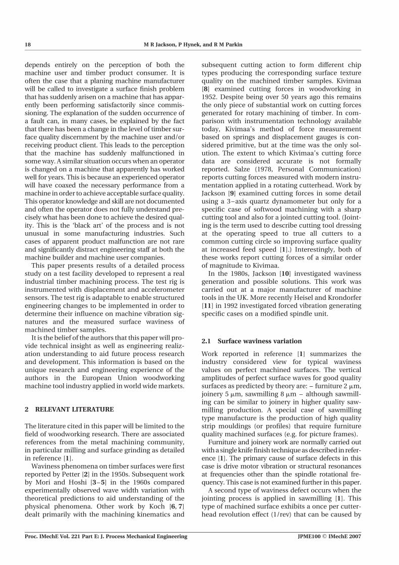
one proud knife or by eccentric running of the cutter-head relative to the machined timber surface.Depending on the severity of this once per revolutioneffect, a waviness defect on themachined timber sur-face will be classified (Fig. 1). Investigation of causesand solutions to this once per revolution effect is thefocus of this paper.
Sawmilling work is normally carried out at thehigher timber feed velocities, typically 50–150 m/min. This process requires the jointing technique tobe applied to achieve the high speeds involved.Ensuring an acceptable waviness quality underthese conditions is the motivation for the workreported here. Table 1 shows data for 1/rev surfacewaviness variation defects in the case where jointingof the cutters is applied to a four knife cutterheadwith a cutting circle of 130 mm diameter. (Cuttingcircle is the diameter of the cutter tips.) This is com-piled from references and confirmed by the authors’research and industrial experience.
A range of wave pitches are aimed for during pro-duction of sawmilling products (mouldings, skirting,architrave, tongue and grooved boarding, cladding).A wave pitch of 1.75 mm is considered at the lowerquality level whereas a wave pitch of 1.25 mm is atthe higher quality level with 1.5 mm being themiddle quality level. These are shown in Table 1.Also shown in the table are the ratios of wave widthfor each nominal wave pitch subjected to a modelledinterference at a1/rev (theory reported in reference[1]). The ratios of Rw(¼Wmin/Wmax) and Wmin/pare presented. (The wave height ratio reported inreference [1] has not been tabulated.) The formerbased on min/max wave width variation and thelatter on the basis of adjacent wave width variation.Both of these ratios are set to 0.7 based on practicalobservation from industrial quality assessments car-ried out by the authors. For a given value of 0.7, thecorresponding values for a1/rev can be calculated
[1]. From Table 1, a1/rev values based on Rw ¼ 0.7are always less than those calculated for the Wmin/p ¼ 0.7 ratio. a1/rev based on the former is typically0.6 times a1/rev calculated for the latter case. This islogical since to get an adjacent wave width variationof 0.7, the amplitude of a1/rev must be greater. Whichmethod of assessment should be used is not estab-lished. For the case where Rw ¼ 0.7 is used as thedesired limit of wave width variation in Table 1, therange of a1/rev across the quality range for sawmillingis determined as nominally 4–2 mm. Using the limitsof Wmin/p ¼ 0.7 results in a1/rev ranging nominallyfrom 7–3.5 mm. Both cases are an exacting require-ment for any planing and moulding machines.These levels of quality are often met for the Wmin/p ¼ 0.7 case, but often not for the Rw ¼ 0.7 case,mainly due to variation in machine state and toolingset up.
Increased numbers of cutters for higher feed speedsresult in larger cutterhead radii and hence shallowerwave heights for a given pitch [1]. The larger radiusand reduced wave height initially lead to the con-clusion that this type of machining condition will bemore sensitive to displacements normal to the surface.Although this is true for each cutter position, the influ-ence of a1/rev is actually reduced because as thenumber of cutters increases the linear distancebetween the high and low points of the wavinesscycle on the timber surface also increases and conse-quently the 1/rev waviness defect is less obvious.Older machinery (circa 1950s) used lower spindlespeeds (3000 r/min) and increased number of cutters(10–12) mainly because of concerns on vibration dueto tooling imbalance and also tooling strength.Latterly, the modern trend is towards higher spindlespeeds (6000 r/min) and less cutters to reduce toolingcosts and set up times. This places the machiningoperation in a region where a1/rev can substantiallyaffect waviness quality on a four or six knife cutter-head. Understanding how to make this four or sixknife high rotational speed operating conditionrobust is at the centre of the work reported here.
2.2 Cutting forces
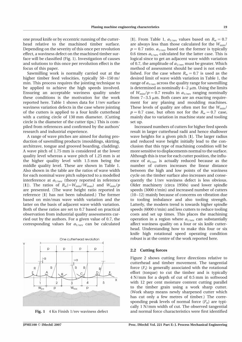
Figure 2 shows cutting force directions relative tocutterhead and timber movement. The tangentialforce (Ft) is generally associated with the rotationaleffort (torque) to cut the timber and is typically4 N/mm for a depth of cut of 0.5 mm in softwoodwith 12 per cent moisture content cutting parallelto the timber grain using a work sharp cutter.(Work sharp means newly sharpened cutter whichhas cut only a few metres of timber.) The corre-sponding peak levels of normal force (Fn) are typi-cally 1 N/mm width of cut. The observed tangentialand normal force characteristics were first identifiedFig. 1 4 Kn Finish 1/rev waviness defect
Planing machine engineering characteristics 19
JPME100 # IMechE 2007 Proc. IMechE Vol. 221 Part E: J. Process Mechanical Engineering
by Kivimaa [8]. Later work (J. Salz, 1978, personalcommunication) [9, 10] supports these observationsfor the limited case of planing timber. Normal forcesare of interest in this work because they may affectthe cutter locus during the initial phase of the cutwhich forms the resultant machined timber surface(for up-milling). (Up-milling is used on most wood-working machines instead of climb milling due toworkpiece feed safety considerations.) Figure 3shows a typical normal force trace from reference[9], obtained at one-sixth operating speed andmeasured using a quartz dynamometer and oscillo-scope instrumentation. By convention, positivenormal cutting forces are defined as those whichpush the cutter tip and timber apart. Negativeforces pull the timber and cutter together. By con-sideration of Figs 2 and 3, it can be postulated(with some confidence) that the initial stage of thecut is essentially a rubbing action where the cutter(supported by a compliant spindle) is exertingpressure on the compliant timber surface untilsuch time as the cutter ‘digs into’ the timber andstarts to form a chip. This idea has been presentedwithout clear evidence (simply limited by instrumen-tation) by both Koch [6, 7] and Kivimaa [8]. In Fig. 3,the proportion of the total cutter engagement timewith the timber that is positive indicates the rubbingregion. This normal cutting force waveform can bescaled against the calculated path length of the tooltip engagement with the timber (L) and thus
determine the length of the positive rubbing regionand the negative cutting region. The proportion ofrubbing and cutting changes with tool geometryand machine settings (and probably machinedynamic characteristics). For the waveform shownin Fig. 3 with p ¼ 1.5 mm and calculated cuttingpath length L ¼ 8.78 mm, the rubbing region extendsto 3.1 mm, i.e. twice the finished wave width p.Figure 3 provides clear evidence that the surfacewave is formed during the rubbing phase of therub-cut cycle. Koch [6, 7] indicates that this may bea machining operation based on a type 1 chipwhere the timber crumbles into a powder ratherthan producing a real (severed) type 3 chip. (Seereferences [6, 7] for a fuller explanation of type 1, 2,and 3 wood chip formation.) Larger wave pitchesand increased depth of cut reduce the positiveregion – i.e. less rubbing occurs, replaced by alonger cutting region.
Normal forces are further increased by the jointingprocess. The circumferential joint land formed by thejointing process as it trues the cutters to a commoncutting circle in effect removes the back clearanceangle g as well as increasing the tip sharpness angleb from 408 to 608. Both of these changes furtherpromote rubbing.
Understanding what happens in this rubbingregion so that the effect on surface waviness (and tex-ture) can be more fully understood is key to control-ling surface finish, tool wear, and powerconsumption. Figure 4 shows how the normal forcechanges with increasing joint land width. Theforces are reported as peak–peak. In actual fact,when jointing is applied, these forces are entirelypositive for the surface generation part of the cuttingcycle, i.e. the rubbing condition applies. Therelationship between joint land and normal cuttingforce as the joint land width increases from sharp(land ¼ 0) to 0.5 mm (normal industrial limit) isclear. These data show that a joint land width of0.3 mm will generate twice the value of normalforce as a joint land width of 0.1 mm. The relation-ship is clearly non-linear but also becoming less sen-sitive as joint land width increases. Joint land widthand normal forces need to be considered in anyfuture analysis simply because each cutter in thecutterhead will have a land width dependent ontool grinding results, relocation eccentricities on
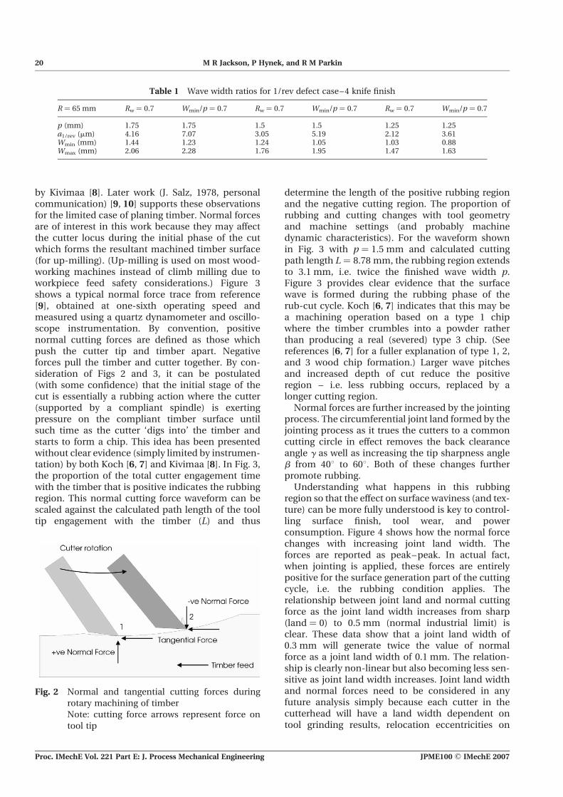
Table 1 Wave width ratios for 1/rev defect case–4 knife finish
R ¼ 65 mm Rw ¼ 0.7 Wmin/p ¼ 0.7 Rw ¼ 0.7 Wmin/p ¼ 0.7 Rw ¼ 0.7 Wmin/p ¼ 0.7
p (mm) 1.75 1.75 1.5 1.5 1.25 1.25a1/rev (mm) 4.16 7.07 3.05 5.19 2.12 3.61Wmin (mm) 1.44 1.23 1.24 1.05 1.03 0.88Wmax (mm) 2.06 2.28 1.76 1.95 1.47 1.63
Fig. 2 Normal and tangential cutting forces during
rotary machining of timber
Note: cutting force arrows represent force on
tool tip
20 M R Jackson, P Hynek, and R M Parkin
Proc. IMechE Vol. 221 Part E: J. Process Mechanical Engineering JPME100 # IMechE 2007

the planing machine spindle, and any vibration pre-sent during the jointing process. The resulting jointland variation cutter to cutter will produce a corre-sponding normal force variation and potentiallydifferent tool tip loci through the timber. This maycause variation in surface wave heights and widths.For this reason, it is essential to measure joint landwidth during machine performance testing.
3 FORCED VIBRATION
The major mechanism that produces surface wavi-ness variation on machined timber is that of forcedvibration. This is unlike milling of metals where‘chatter’, i.e. instability is in the main structure anddrive systems are a major cause of surface wavinessdefects, although forced vibration also producessurface defects in milling of metals. Forced vibrationcan also influence the surface waviness of precisionground metal components [9]. A further mechanismfor surface waviness defect generation is due tomisaligned spindle bearings that produce a twice
Fig. 3 Typical normal force waveform
Fig. 4 Effect of jointing on normal cutting force Fn
Planing machine engineering characteristics 21
JPME100 # IMechE 2007 Proc. IMechE Vol. 221 Part E: J. Process Mechanical Engineering
per revolution vibration that reproduces onthe machined timber surface. Superficially, this sur-face defect on a four knife jointed cutterhead seemsthe same as for case 1 [1] where a 1/rev interferingforced vibration at half the spindle speed in singleknife finish machining conditions produces a light–heavy–light–heavy wave pattern on the timber sur-face. However, the engineering procedure to providea solution is different for each case. In the case oftwice per revolution vibration, the bearings need tobe aligned correctly and in the once per two revolu-tions case, the forcing frequency from the half spin-dle speed drive motor needs to be removed fromthe cutter spindle via motor/pulley balancing,dynamic isolation, or structural characteristic modi-fication or a combination of these solutions.
Cutting forces generated when machining timberoccur at high frequencies (5 kHz is typical). There-fore, the forces applied to the machine structureare correspondingly small and do not normallyinduce chatter generation and correspondingsurface defects. With timber surfaces, the degra-dation takes the form of width/height modulationof surface waves resulting on the timber from therotary machining action modified by a combinationof forced vibration and tool sharpening errors.
This paper is concerned with forced vibration of afour knife jointed cutterhead where the majorvibration component is due to spindle rotational fre-quency, usually caused by imbalance and structuraldeflection. The frequency range of interest, associ-ated with typical industrial applications is75–400 Hz. The lower value of 75 Hz correspondsto a rotational speed of 4500 r/min, whereas 400 Hzcorresponds to a 6000 r/min spindle speed (100 Hz)multiplied by the number of cutters in the cutter-head – four in this case. The cutter passing frequencymust be considered because of the possibility ofsubtle cutting force effects (not chatter). It isnot normal practise to joint cutterheads above6000 r/min spindle speeds, although there is noclear technical evidence for this limit [9].
It is possible to dynamically model the broadeffects of forced vibration. The cutterhead and spin-dle assembly stiffness are assumed to be infinite, i.e.the variables for support stiffness include both spin-dle bearing and support structure stiffness. Typicalmodelling activity based on classical equations canbe undertaken in MATLAB#. Detailed reportage isthe subject of a future paper. The results of suchmodelling correspond closely to practically ident-ified cutterhead natural frequencies (by impulsemethod and variable speed method). It is clear thatmajor resonances occur within the operating rangeof these types of woodworking machines. This isnot unusual in industrial equipment of this generalsize. Given this, it is entirely possible for the slight
imbalance due to the small endemic eccentricrotation of a heavy cutterhead to generate significantforces. Typical forces at the spindle speed of 6000 r/min and cutterhead mass of 15 kg are þ/212 N at100 Hz. While these forces are not high, the supportstiffness values of typically 30 N/mm mean thatþ/22.5 mm are possible just based on static calcu-lations. In practise, the values can be greater thanthis due to resonance effects.
Eccentric running of the cutterhead spindle com-prises of two parts: static eccentricity due to minorimperfections in component manufacture anddynamic eccentricity at the operating speedresulting from spindle/cutterhead imbalance inter-acting with support structure flexibility. Imbalancealso comprises of two components: due to staticeccentricity of the cutterhead mass, and imbalanceforces due to any further eccentricity increase dueto the flexible nature of the support structure androlling element bearing system. These imbalancecomponents combine to produce a rotational speedsensitive dynamic eccentricity initiated by staticimbalance that interacts with support system com-pliance, thus, producing increasing eccentricitywith rotational speed.
Depending on the position of the jointing device,this dynamic eccentricity and also the static eccentri-city of the cutters can be dressed out. Due to cuttergrinding off the planermoulder and subsequent relo-cation on the cutterhead spindle. This has been thepremise of the jointing approach for the past 50years. For machining conditions at the lower qualityend of the market, this has indeed worked. As timbermachining companies try to expand (or indeedretain) their markets by improving quality, the exist-ing process shows up once per revolution surfacewaviness modulation effects that are often con-sidered defects. Purists would have the jointingdevice located at the point of cutting to be surethat all eccentricities are removed at the cuttingpoint, but this is not practical. More usually jointingdevices are located at either the 11 o’ clock or2 o’clock positions when viewed from the front of ahorizontal top head as shown in Figs 5 and 6. Con-cerns about these locations exist because it is postu-lated that non-circular cutterhead orbits willgenerate a jointed shape on the cutters that doesnot compensate the initial inaccuracies of cuttertracking resulting from the cutter grinding and relo-cation on the machine spindle. Furthermore, insome cases, the jointing device itself can modifythe jointed cutter tracking orbit due to jointervibration excited by cutterhead imbalance (the join-ter behaves like a cam grinding device) or by modify-ing structural dynamics and thus influencing spindleorbit – in the case of removable jointing devices forexample.
22 M R Jackson, P Hynek, and R M Parkin
Proc. IMechE Vol. 221 Part E: J. Process Mechanical Engineering JPME100 # IMechE 2007

The random nature of these tooling and machineryinduced cutter tracking modifications from the pointwhen the machinery is first assembled and alsoduring service life, subtlety change themachining per-formance of very expensive and heavy machinery(typically 10 tonnes), where the sole design purposeof these machines is to produce high-qualitymachined surfaces.
To investigate these effects, a special purposetest rig was designed based on a top head unitof a high-speed planing and moulding machine.This head had variable performance in industryand thus was a good candidate for systematicinvestigation and modification for improvement ofmachining quality.
4 EXPERIMENTAL FACILITY
The special purpose test rig used for engineering andwood machining investigations is shown in Fig. 5.The test rig comprises of a main spindle unit anddrive motor, integrated timber feed rollers (feedingtimber from right to left) located on a one tonnesteel reinforced concrete base. The base wasmounted on amachine tool foundation via industrialanti-vibration mounts.
At a main spindle speed of 4350 r/min, four knifejointed operation, and the integrated timber feed-works set at the following speeds (measured on thetimber surface), the corresponding cuttermarkwidths are:
36 m/min ¼ 2.0 mm wave pitch26 m/min ¼ 1.5 mm wave pitch17 m/min ¼ 1.0 mm wave pitch
Careful design and benchmarking with a full pro-duction machine confirmed that this test rig gaverepresentative performance. Figure 7 shows across-sectioned view of the top head structure ofthe test rig. The main spindle housing is shownbehind the fence line (FS) timber guide. This spindlehousing incorporates a super precision ball bearingpair in back to back configuration. Outer race diam-eter is 100 mm. The outboard bearing housinglocated on the left side of the arrangement at thenear side (NS) incorporates a single row super pre-cision deep groove design of 85 mm outer race diam-eter. A Tufnol sleeve is located inside the bearinginner ring. The cutterhead spindle locates in thebore of the Tufnol sleeve. This arrangementprovides a run time support for the cutterhead spin-dle. The Tufnol sleeve is keyed to the cutterheadspindle. The outboard bearing housing is removed
Fig. 5 Test rig for planing investigation
Fig. 6 Standard structure – front view
Planing machine engineering characteristics 23
JPME100 # IMechE 2007 Proc. IMechE Vol. 221 Part E: J. Process Mechanical Engineering

by releasing a lock nut when cutterhead removal isrequired. The extra support from the outboardbearing allows cutter jointing to be carried out toimprove timber surface quality at higher feedspeeds. The fit of the spindle in the Tufnol sleeve isH7-g6 (close location fit), this can introduce a dia-metrical clearance of 5–90 mm theoretically. In prac-tise, the limits are controlled by selection to produce5–25 mm.
The jointing device is of the removable type. To usethe jointer, the chipbreaker unit has to be raised,then the jointer is clamped in position (Fig. 5).These two actions significantly alter the dynamicsof the standard machine structure.
Initial static stiffness measurements at the FS andNS of the structure showed the FS to be 105 N/mmwith the NS (outboard bearing side) 30 N/mm. Thelower stiffness at the NS may well be due in part tothe clearance fit between the Tufnol sleeve boreand the cutterhead spindle. The stiffness graphs donot indicate a classic non-linearity when the clear-ance is traversed. It is thought that assembly misa-lignments effectively linearize this effect. The othercontributors to low stiffness at the NS are deflectionof the supporting structure as well as the internalclearance of the deep groove outboard bearing.Both of these are secondary to the effect due to theTufnol sleeve. While the overall machine construc-tion seems adequate for planing timber, it is clearthat subtle detail differences exist at the interfacesbetween critical components.
The standard type of cutterhead for this machinewould have originally been mechanical collett and
cone location based. This system allows the cutter-head to be centred on the spindle within certainbroad limits. From experiments the degree of cutter-head eccentricity resulting from this centeringapproach is within the range 5–75 mm. This rangeis determined by the eccentricity of the spindle, theeccentricity of the cone in the cutterhead and theeccentricity of the cone on the collett. By rotatingthe phase angle of each element eccentricity the5–75 mm range can be obtained. The cutterheaddiameter is 145 mm with a mass of 10 kg, thus amaximum imbalance due to the cone and collettlocation system is 750 gm . mm, considering staticimbalance. While machine designers had introducedthis cone and collett system in the 1950s, in actualfact a more reliable (but possibly on average moreinferior) result could have been achieved with aplain H7-g6 location fit. There is no evidence thatthe collets were used to find the best point ofsmooth running. Usually, operators just reporteddegradation of machined surface quality, whenunfavourable balance conditions resulted fromrandom relocation of these eccentric components.In the light of this experience and analysis, thecutterhead on the test rig was modified to includetwo hydraulically contracting bushes (known asHydrogrip bushes) to improve centering ability towithin 5–10 mm. The effects of the cone and collettsystem were simulated (approximately) by additionof imbalance masses. The cutterhead was also modi-fied to include gauging rings at each end so that non-contacting displacement transducers (NCDT)(capacitive type from Wayne Kerr) could be used to
Fig. 7 Test rig arrangement – view in timber feed direction
24 M R Jackson, P Hynek, and R M Parkin
Proc. IMechE Vol. 221 Part E: J. Process Mechanical Engineering JPME100 # IMechE 2007
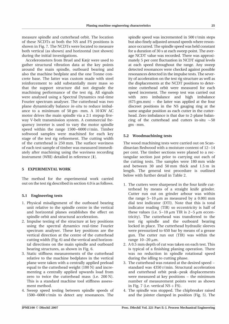
measure spindle and cutterhead orbit. The locationof these NCDTs at both the NS and FS positions isshown in Fig. 7. The NCDTs were located to measureboth vertical (as shown) and horizontal (not shown)during the initial investigations.
Accelerometers from Bruel and Kæjr were used togather structural vibration data at the key pointsaround the main spindle, outboard bearing andalso the machine bedplate and the one Tonne con-crete base. The latter was custom made with steelreinforcement to add substantially more mass sothat the support structure did not degrade themachining performance of the test rig. All signalswere analysed using a Spectral Dynamics real-timeFourier spectrum analyser. The cutterhead was twoplane dynamically balance in-situ to reduce imbal-ance to a minimum of 50 gm . mm. A 10 KW ACmotor drives the main spindle via a 2:1 stepup five-way V-belt transmission system. A commercial fre-quency inverter is used to vary the motor spindlespeed within the range 1500–6000 r/min. Timbersoftwood samples were machined for each keystage of the test rig refinement. The cutting widthof the cutterhead is 250 mm. The surface wavinessof each test sample of timber was measured immedi-ately after machining using the waviness recordinginstrument (WRI) detailed in reference [1].
5 EXPERIMENTAL WORK
The method for the experimental work carriedout on the test rig described in section 4.0 is as follows.
5.1 Engineering tests
1. Physical misalignment of the outboard bearingunit relative to the spindle centre in the verticaland horizontal planes establishes the effect onspindle orbit and structural acceleration.
2. Impulse testing of the structure at key positionsusing the spectral dynamics real-time Fourierspectrum analyser. These key positions are thevertical direction at the centre of the cutterheadcutting width (Fig. 6) and the vertical and horizon-tal directions on the main spindle and outboardbearing structures, as shown in Fig. 6.
3. Static stiffness measurements of the cutterheadrelative to the machine bedplates in the verticalplane were taken with a centrally applied preloadequal to the cutterhead weight (100 N) and incre-menting a centrally applied upwards load fromzero to twice the cutterhead mass (i.e. 200 N).This is a standard machine tool stiffness assess-ment method.
4. Sweep speed testing between spindle speeds of1500–6000 r/min to detect any resonances. The
spindle speed was incremented in 500 r/min stepsbut also finely adjusted around speeds where reson-ance occurred. The spindle speedwas held constantfor a duration of 30 s at each sweep point. The aver-age NCDT value was recorded. There was approxi-mately 5 per cent fluctuation in NCDT signal levelsat each speed throughout the range. Any sweepdetected resonances were checked against possibleresonances detected in the impulse tests. The sever-ity of acceleration on the test rig structure as well asthe displacements at the NCDT positions to deter-mine cutterhead orbit were measured for eachspeed increment. The sweep test was carried outwith zero imbalance and high imbalance(675 gm.mm) – the latter was applied at the fourdiscreet positions in the NS gauging ring at thesame angular position as each cutter in the cutter-head. Zero imbalance is that due to 2-plane balan-cing of the cutterhead and cutters in-situ �50gm . mm.
5.2 Woodmachining tests
The wood machining tests were carried out on Scan-dinavian Redwood with a moisture content of 12–14per cent. The timber sections were planed to a rec-tangular section just prior to carrying out each ofthe cutting tests. The samples were 180 mm wideand between 30 and 50 mm thick and 1.5 m inlength. The general test procedure is outlinedbelow with further detail in Table 2.
1. The cutters were sharpened in the four knife cut-terhead by means of a straight knife grinder.Cutter run out on grinder arbour was withinthe range 5–10 mm as measured by a 0.001 mmdial test indicator (DTI). Note that this is totalindicator reading (TIR) so eccentricity is half ofthese values (i.e. 5–10 mm TIR is 2–5 mm eccen-tricity). The cutterhead was transferred to thetest rig spindle and the outboard bearinglocked in place. The cutterhead hydraulic sleeveswere pressurized to 650 bar by means of a greasegun. The cutter run out (TIR) was within therange 10–20 mm.
2. A 0.5 mm depth of cut was taken on each test. Thisis typical of a finishing planing operation. Therewas no reduction in spindle rotational speedduring the idling to cutting phase.
3. The cutterhead was rotated at the desired speed –standard was 4350 r/min. Structural accelerationand cutterhead orbit peak–peak displacementswere measured at key positions – the minimumnumber of measurement points were as shownin Fig. 7 (i.e. vertical NSþ FS).
4. The spindle was stopped. The chipbreaker raisedand the jointer clamped in position (Fig. 5). The
Planing machine engineering characteristics 25
JPME100 # IMechE 2007 Proc. IMechE Vol. 221 Part E: J. Process Mechanical Engineering

spindle was started again to run at the operatingspeed. Jointing was carried out. It was also possibleto measure the cutterhead gauging ring displace-ment relative to the jointer in the jointing plane atboth the FS and NS positions. This was done usinga separate NCDT mounted on the jointer carriage.
5. When jointing was judged to have occurred on allfour cutters, the spindle was stopped and thestatic cutter run outs measured at both FS andNS positions. The joint land width was measuredusing an eyepiece with graticule of 0.1 mmgraduation.
6. After jointing, the chipbreaker was lowered andthe spindle was run at the desired cutting speed(normally the same as the speed at which jointingwas carried out). A test cut at the set feed speedwas then carried out. A typical time for signalacquisition was 3 s. Longer pieces of timber wereused to provide longer acquisition times asrequired. Vibration levels during cutting werealso recorded via the Spectral Dynamics real-time Fourier spectrum analyser.
7. The surface waviness of the machined timbersamples was measured using the WRI.
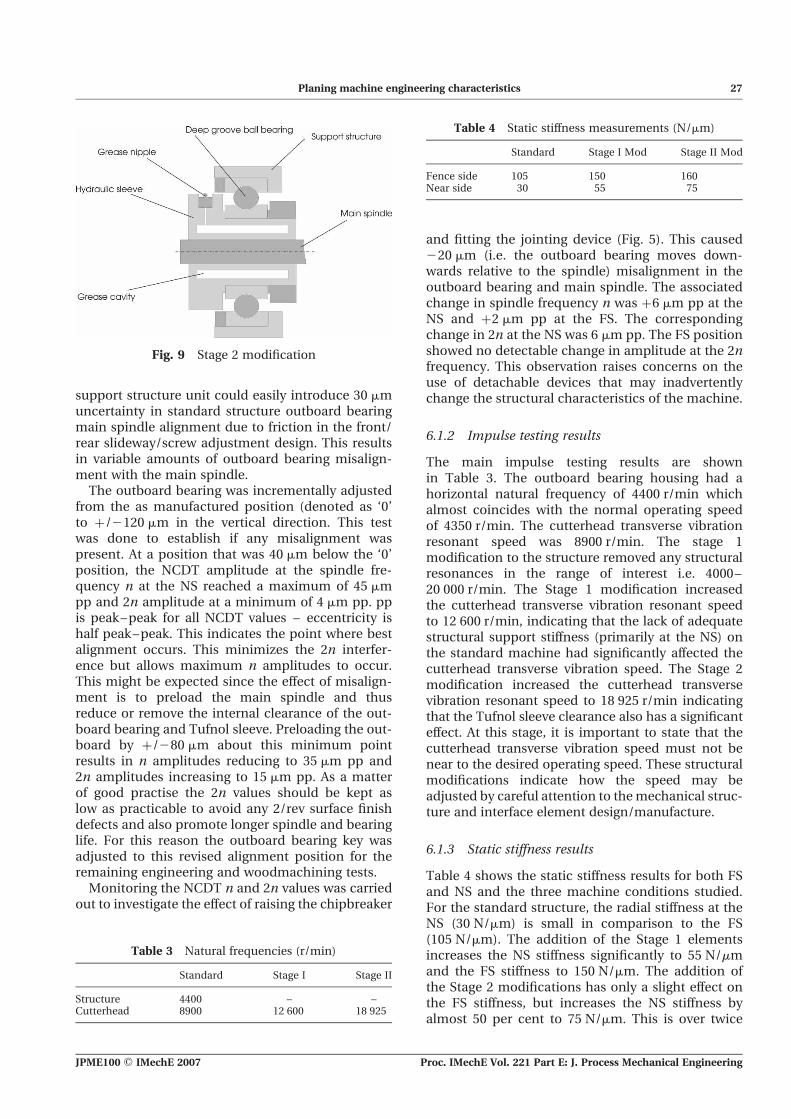
The above test programs were implemented forthe standard machine arrangement (standard struc-ture Fig. 6), a stiffer structure implemented by stif-fening elements at both the FS and NS, includingadditional outboard bearing slide clamps (Stage 1modification as shown in Fig. 8) and a furthermodification to remove the Tufnol sleeve clearancewith the spindle by means of a substitute hydrauli-cally contracting sleeve (Stage 2 modificationshown in Fig. 9). It should be noted that Stage 2comprises of the structural stiffening elements ofStage 1 plus the hydraulically contracting sleeveshown in Fig. 9.
6 TEST RESULTS AND ANALYSIS
A large amount of test data have been obtained fromthis test work. A selection is presented here in Tables3 to 5 and Figs 7 to 13 to show the key findings of theresearch.
6.1 Engineering test results
A preliminary vibration assessment of the test rigshowed that the rigid body mode vibration of themachine concrete base and bedplate section wastwo orders of magnitude lower than themain spindlesupport structure vibration. There was no frequencycomponent associated with the main drive motors(spindle and feedworks). There was no vibrationbeating due to the V-belt drives.
6.1.1 Misalignment investigation results
During the initial vibration survey, it was discoveredthat the normal fitment dual rise and fall leadscrewarrangement (one at the FS and one at the NSlinked by a common actuation shaft) for the spindle
Fig. 8 Stage 1 modification – front view
Table 2 Experimental tests – measured parameters
Parameter Comments
Structural displacement and cutterhead orbit at NS, FSvertical and horizontal directions for a range ofoperating speeds
Accelerometers placed on machine structure to confirm any structuraldisplacements in relation to cutterhead orbit relative to machinebed measured by NCDTs
Radial stiffness of cutterhead normal toplane of timber surface
Static measurement via centrally applied load and measurement ofcutterhead displacement at FS and NS positionsusing embedded NCDTs
Natural frequency of cutterhead and bearing assembly Static impulse method: to determine how structural modificationsaffect this parameter
Cutterhead orbit (jointing phase) [B2 J1, C2 J2] To detect any orbit differences between the cutting(B, C) and jointing plane
Static jointed cutter tracking To indicate results of jointing process and confirm any relativeradial displacement between jointing stone and cutter
Cutterhead orbit (cutting phase) [B2 Bc, C2 Cc] To detect any changes in spindle orbit between jointing andcutting phase
Surface waviness pitch and height data (p ¼ 1.5 mm) To confirm the resulting machined wood surface waviness pitch,height and variation
All of the above measured for standard structure, Stage 1 and Stage 2 modified structures.
26 M R Jackson, P Hynek, and R M Parkin
Proc. IMechE Vol. 221 Part E: J. Process Mechanical Engineering JPME100 # IMechE 2007
support structure unit could easily introduce 30 mmuncertainty in standard structure outboard bearingmain spindle alignment due to friction in the front/rear slideway/screw adjustment design. This resultsin variable amounts of outboard bearing misalign-ment with the main spindle.
The outboard bearing was incrementally adjustedfrom the as manufactured position (denoted as ‘0’to þ/2120 mm in the vertical direction. This testwas done to establish if any misalignment waspresent. At a position that was 40 mm below the ‘0’position, the NCDT amplitude at the spindle fre-quency n at the NS reached a maximum of 45 mmpp and 2n amplitude at a minimum of 4 mm pp. ppis peak–peak for all NCDT values – eccentricity ishalf peak–peak. This indicates the point where bestalignment occurs. This minimizes the 2n interfer-ence but allows maximum n amplitudes to occur.This might be expected since the effect of misalign-ment is to preload the main spindle and thusreduce or remove the internal clearance of the out-board bearing and Tufnol sleeve. Preloading the out-board by þ/280 mm about this minimum pointresults in n amplitudes reducing to 35 mm pp and2n amplitudes increasing to 15 mm pp. As a matterof good practise the 2n values should be kept aslow as practicable to avoid any 2/rev surface finishdefects and also promote longer spindle and bearinglife. For this reason the outboard bearing key wasadjusted to this revised alignment position for theremaining engineering and woodmachining tests.
Monitoring the NCDT n and 2n values was carriedout to investigate the effect of raising the chipbreaker
and fitting the jointing device (Fig. 5). This caused220 mm (i.e. the outboard bearing moves down-wards relative to the spindle) misalignment in theoutboard bearing and main spindle. The associatedchange in spindle frequency n was þ6 mm pp at theNS and þ2 mm pp at the FS. The correspondingchange in 2n at the NS was 6 mm pp. The FS positionshowed no detectable change in amplitude at the 2nfrequency. This observation raises concerns on theuse of detachable devices that may inadvertentlychange the structural characteristics of the machine.
6.1.2 Impulse testing results
The main impulse testing results are shownin Table 3. The outboard bearing housing had ahorizontal natural frequency of 4400 r/min whichalmost coincides with the normal operating speedof 4350 r/min. The cutterhead transverse vibrationresonant speed was 8900 r/min. The stage 1modification to the structure removed any structuralresonances in the range of interest i.e. 4000–20 000 r/min. The Stage 1 modification increasedthe cutterhead transverse vibration resonant speedto 12 600 r/min, indicating that the lack of adequatestructural support stiffness (primarily at the NS) onthe standard machine had significantly affected thecutterhead transverse vibration speed. The Stage 2modification increased the cutterhead transversevibration resonant speed to 18 925 r/min indicatingthat the Tufnol sleeve clearance also has a significanteffect. At this stage, it is important to state that thecutterhead transverse vibration speed must not benear to the desired operating speed. These structuralmodifications indicate how the speed may beadjusted by careful attention to themechanical struc-ture and interface element design/manufacture.
6.1.3 Static stiffness results
Table 4 shows the static stiffness results for both FSand NS and the three machine conditions studied.For the standard structure, the radial stiffness at theNS (30 N/mm) is small in comparison to the FS(105 N/mm). The addition of the Stage 1 elementsincreases the NS stiffness significantly to 55 N/mmand the FS stiffness to 150 N/mm. The addition ofthe Stage 2 modifications has only a slight effect onthe FS stiffness, but increases the NS stiffness byalmost 50 per cent to 75 N/mm. This is over twice
Table 4 Static stiffness measurements (N/mm)
Standard Stage I Mod Stage II Mod
Fence side 105 150 160Near side 30 55 75
Fig. 9 Stage 2 modification
Table 3 Natural frequencies (r/min)
Standard Stage I Stage II
Structure 4400 – –Cutterhead 8900 12 600 18 925
Planing machine engineering characteristics 27
JPME100 # IMechE 2007 Proc. IMechE Vol. 221 Part E: J. Process Mechanical Engineering

the standard structure NS stiffness and is comparableto the single deep groove rolling element bearing stiff-ness. This indicates that should further increases instiffness be sought for the NS position then a doublerow angular contact arrangement similar to the FSposition should be investigated. This would lead toa substantial redesign of both the outboard bearingassembly and the main spindle unit due to the factthat three super precision heavy duty preloaded bear-ings in line would present considerable manufactur-ing difficulties. Changing the emphasis of the designto provide equal support at the outboard and fenceside positions seems logical. The third (rear) bearingin the main spindle unit could then be made asimple deep groove arrangement to provide powertransmission support.
6.1.4 Sweep testing results
Sweep test results are presented for the NS position asthese are themore pronounced, generally being two tothree times those at the FS position. Sweep tests car-ried out on the standard structure for the ‘0’ imbalancecase are characterized by a steady non-linear increasein structural vibration with spindle speed. This
structural vibration reaches a maximum of 30 mm ppat 4400 r/min and then reduces as the speed increasespast the structural resonance. Table 5 shows thechange in NCDT values at the NS throughout thespeed range for the standard structure and the Stages1 and 2 modifications. The NS NCDT displacement(Fig. 10) actually reduces in a linearmanner as spindlespeed increases due to the structural vibration effects.The fact that the standard structure with ‘0’ appliedimbalance shows a reduction of 4 mm pp from thestatic run out value of 10 mm pp is due to the com-pensatory nature of the structural resonance at4400 r/min. This observation supports operationalpractise where certain machines exhibit better per-formance than others, probably caused my minorchanges in operating speed and subtle changes instructural resonant frequency.
For the 675 gm . mm imbalance case, the struc-tural vibration on the standard structure exhibits apronounced structural resonance at 4400 r/min.This is also evident from the NS NCDT values inFig. 10. The relative motion between the forcingimbalance vector and the structural vibration areshown. The level of spindle displacement (35 mmpp) measured by the NCDTs at the NS at 4400 r/minis considerably greater than for the ‘0’ imbalancecase. The NCDT value reduces quickly past reson-ance to 3 mm pp greater than the static run out of10 mm pp. Below resonance, the imbalance vectorand vertical displacement vectors are in phase,whereas above resonance, they are in anti-phase.The influence of the resonance increases with imbal-ance value. With this characteristic it is clear that
Fig. 10 Standard structure resonance
Table 5 Sweep test data 1500–5000 r/min mm p-p NCDT
NS
Standard Stage I Mod Stage II Mod
‘0’ imbalance 24 9 0675 gm . mm imbalance 3a 23 6
aActually 30 mm at 4400 r/min resonance
28 M R Jackson, P Hynek, and R M Parkin
Proc. IMechE Vol. 221 Part E: J. Process Mechanical Engineering JPME100 # IMechE 2007

jointing and keeping a good quality surface finishwould seem highly improbable. Practical experienceconfirms this.
The Stage 1 modification removes this structuralresonance and Table 5 shows the effect on cutter-head run out values through the speed range. Theeffects of imbalance coupled with rotational speedcreate a steady non-linear increase in cutterheadrun out as speed increases for the ‘0’ imbalancecase reaching 9 mm pp at 5000 r/min (Fig. 11). Theapplication of the 675 gm . mm imbalance creates acorresponding 23 mm pp increase. There is no com-pensatory effect from the structural imbalance,hence, the run out is greater than for the standardstructure. In effect, the imbalance vector at the NSis now reacting against the combined stiffness ofthe spindle/cutterhead and the Tufnol sleeve/out-board bearing compliance.
The addition of the hydrogrip outboard bearing forthe Stage 2 modification reduces the sweep speedchange to effectively zero for the ‘0’ imbalancecase, with a corresponding value of 6 mm pp for the675 gm . mm imbalance case (Table 5, Fig. 12).
These tests show that the standard structure isweak dynamically, in the outboard bearing structureespecially. This coupled with the Tufnol sleeve clear-ance allows considerable orbit change with speedand imbalance effects. By stiffening the structureand removing the outboard bearing support sleeveclearances, a more robust mechanical structure isachieved.
6.2 Woodmachining results
The effects of engineering changes are evaluated viathe wood machining tests for the different stages ofmachine modification. The test rig was subjected toover 50 cutting tests.
6.2.1 Standard structure
The machined timber surface trace in Fig. 13 for theNS is typical for the zero imbalance condition(,60 gm . mm) and for a surface wave pitch p of1.5 mm produced by the standard structure.Table 6 shows typical vibration data during the test.The difference in cutterhead run out at the spindlefrequency n at the NS vertical position (i.e. cuttingplane) between the jointing and cutting stages is5 mm. The static cutter tracking errors are 15 mm ppas is the 1/rev surface waviness amplitude inFig. 13. The periodic marking at four times thewave pitch p is clearly visible from the surface trace.
It is not possible to make a clear analysis of whatis happening in this machine operational statebecause there are so many variables interacting.While a deeper and more extensive focused investi-gation on this case could be done, it was deemedpointless since the test work had revealed thatserious dynamic structural flaws existed andneeded to be resolved. The phased improvementthrough Stages 1 and 2 modifications was, there-fore, pursued. Speculatively, the most likely expla-nation of the standard structure observations isthat the structural vibration makes the jointermove relative to the cutterhead and thus dresses a1/rev shape onto the cutters. This is complicated
Fig. 11 Imbalance response for Stage 1 structure
Fig. 12 Imbalance response for Stage 2 structure
Fig. 13 Standard structure NS surface trace
p ¼ 1.5 mm
Planing machine engineering characteristics 29
JPME100 # IMechE 2007 Proc. IMechE Vol. 221 Part E: J. Process Mechanical Engineering

by the fact that the cutterhead is also vibrating inthe vertical plane at the cutting point, so a com-bined effect results. The application of 675 gm . mmimbalance at any cutter position at the NS resultsin displacement values approximately twice aslarge as for the zero imbalance condition. The15 mm pp 1/rev amplitude on the NS trace inFig. 13 is typical of the poor quality achieved onthis type of production machine. Even though amachine weighs 6 tonnes, comprising of cast ironand high grade steel, the fundamental designflaws that produce the structural resonance coupledwith the detailed weaknesses associated with slidefriction and Tufnol bush clearances lead one tounderstand that initial superficial appearances canhide a host of weaknesses at the micrometre level.
6.2.2 Stage 1 modification
A typical surface trace result for the Stage 1 modifi-cation is shown in Fig. 14. The same wave pitch ofp ¼ 1.5 mm is maintained. The corresponding testresults summary is in Table 6. The NCDT change atthe NS cutting point between jointing and cuttinghas reduced to 2 mm pp. This is less than half thatfor the standard structure. Significantly, the level of2 mm shows that higher surface qualities shouldresult. However, the static cutter tracking errorsafter jointing at the NS are 10 mm pp compared to1 mm pp at the FS. This suggests that the cutterheadis adopting a slightly bent shape due to the dynamicimbalance effects initiated by the small residual
imbalance and thus deflecting across the clearancebetween the spindle and the NS Tufnol sleeve. Sig-nificantly, in Fig. 14, the surface waviness trace atthe NS exhibits a 6 mm pp 1/rev effect and whilethis does not compare well with the change betweenjointing and cutting at the NS of 2 mm pp, it doesillustrate the level of improvement achieved whencompared with the 15 mm pp of the surfacemachined by the standard structure.
6.2.3 Stage 2 modification
A typical surface trace result for the Stage 2 modifi-cation is shown in Fig. 15. The same wave pitch ofp ¼ 1.5 mm is maintained. The corresponding testresults summary is in Table 6. There is no measurabledifference in the cutterhead orbit between jointingand cutting and similarly no measurable staticcutter tracking errors as shown in Table 6. Themeasured surface waviness is further improved tothe point where the limitations of the WRI arereached. Even with the use of a roller stylus, thegrain effects of the timber are starting to distort thehigher surface quality waveform as seen in the NStrace in Fig. 15. The achieved surface waviness is2 mm pp compared to 15 mm pp on the standardstructure.
When a large (675 gm . mm) imbalance is appliedat the NS as a test of robustness, there is an increasein 1/rev waviness on themachined timber surface forthe standard structure to 30 mm pp, while the sametest on the Stage 2 structure results in a 1/rev
Table 6 Experimental results – normal imbalance
Standardstructure
Stage 1modification
Stage 2modification
Cutterhead NF (r/min) 8900 12 600 18 925
ParameterPosition FS NS FS NS FS NSRadial stiffness (N/mm) 105 30 150 55 160 75NCDT joint-cutting (mm) 3 5 0 2 0 0Cutter tracking errors (mm) 7 15 1 10 0 0Surface 1/rev amplitude (mm) 6 15 3 6 1 2
Fig. 14 Stage 2 modification NS surface trace
p ¼ 1.5 mm
Fig. 15 Stage 2 modification NS surface trace
p ¼ 1.5 mm
30 M R Jackson, P Hynek, and R M Parkin
Proc. IMechE Vol. 221 Part E: J. Process Mechanical Engineering JPME100 # IMechE 2007

waviness of 3 mm pp. The Stage 2 arrangement is notonly capable of producing superior surface qualitybut will also achieve this in a robust manner leadingto greater consistency in machine operation. This inturn will increase operator confidence, reducemachine downtime, and generate greater output ina more efficient manner.
7 DISCUSSION
The test results achieved in this work have shownthat it is possible to make modifications to a wood-working machine tool structure in stages and quan-tify the effects of these changes both in terms ofmeasured surface waviness quality on the machinedtimber samples as well as key engineering par-ameters at the heart of the machining process. Sup-port stiffness in the vertical direction for ahorizontal spindle unit has been shown to be amajor factor in achieving high quality surfaces. Thestandard structure was sufficiently weak dynami-cally, that the raising of the chipbreaker and attach-ment of the jointing device were sufficient tochange the NS spindle orbit by 6 mm pp . This is suf-ficient to cause a significant surface defect. Misalign-ment due to main spindle and outboard bearingsbeing on separate slideways linked by dual rise andfall screws can cause significant changes in spindleorbit at both the spindle rotational frequency andthe first harmonic. Orbit change between jointingand cutting was thought to be an issue, but a tightcorrelation could not be observed. It can be saidthat as the structural integrity of the machineincreases, the measured orbit change between joint-ing and cutting does reduce. However there is no cor-relation to measure static cutter run outs – this is auseful conclusion because this is one way the woodmachining trade believes they can quantify if agood surface is likely. The answer seems to be thatthe machine must possess a high radial stiffness ide-ally 100 N/mm and no radial clearances in eithersleeves or bearings greater than 3 mm.
Additional work to observe joint land width on cut-ting forces and spindle run out at 1/rev and the cutterpassing frequency should yield information on theinfluence of these parameters on surface wavinessquality. It is interesting to see how the cutterheadnatural frequency increases with the NS static stiff-ness as shown in Fig. 16. The proximity of the knifepassing frequency at for example 4500 r/min withfour cutters shows the potential problem withmechanically stiff structures. This suggests variationsin joint land width and hence normal cutting forcemay couple with resonance energy to cause wavemark variation. This is the subject of further research.
Also the subject of current and future research isthe idea that a purely mechanical solution toimprove waviness (and also texture) has reached anatural limit (Fig. 17). The potential of activesystems should be explored to sense the machinedsurface quality and actively control the cutterheaddisplacement to always achieve the desired result atthe desired feed speed. Such systems have the poten-tial to revolutionize the dry machining of materialssuch as wood and plastic. Initial simulation work[12] has shown this to be viable and investigationsusing a smart spindle unit will be reported in afuture paper.
8 CONCLUSIONS
Structural stiffness is the first requirement inachieving good quality machined timber surfaces.Structural mass alone is of no use. The detailedstructural integrity across location sleeves is suffi-ciently low to cause poor machined surface quality.The combined result of good structural stiffness andintegral hydraulically contracting location sleevescan produce combined stiffness of the order of100 N/mm. This is sufficient to achieve good qualityFig. 16 Radial stiffness of cutterhead support
Fig. 17 Technology road map for future machine
design
Planing machine engineering characteristics 31
JPME100 # IMechE 2007 Proc. IMechE Vol. 221 Part E: J. Process Mechanical Engineering

surfaceswhere the 1/rev amplitude is less than2 mmata wave pitch of 1.5 mm. The higher quality surfaceswith awave pitch less than 1.5 mmare only achievableunder particular unknown circumstances and shouldbe the subject of further research.
REFERENCES
1 Jackson, M. R., Parkin, R. M., and Brown, N. Waveson wood. Proc. Instn Mech. Engrs, Part B: J. Engineer-ing Manufacture, 2002, 216, 475–497. ISSN 09 54-4054.
2 Petter, J. C.Development work on wood planers. ForestProd. Res. Soc., 1954, 543, 1–3.
3 Mori, M. and Hoshi, T. Studies on surfacing ofwood with planer (I). Bull. Gov. Forest Exp. Station,1964, 160, 1–24.
4 Mori, M. and Hoshi, T. Studies on surfacing of woodwith planer (II). Bull. Gov. Forest Exp. Station, 1964,163, 1–18.
5 Mori, M. Studies on surfacing of wood with planer (IV).Bull. Gov. Forest Exp. Station, 1964, 163, 1–13.
6 Koch, P. An analysis of the lumber planing process: partI. Forest Prod. J., 1955, pp. 255–264.
7 Koch, P. An analysis of the lumber planing process: partII. Forest Prod. J., 1956, 6(10), pp. 393–402.
8 Kivimaa, E. Cutting forces in woodworking. PhD Thesis,University of Helsinki, 1950.
9 Jackson, M. R. and Buttery, T. C. Some effects ofmachine parameters on cutting forces and surfacegeometry in rotary planing of wood and polymers.Second Joint Polytechnics Symposium on Manufac-turing engineering, Lanchester Polytechnic, June1979, pp. 196–201.
10 Jackson, M. R. Some effects of machine characteristicson the surface quality of planed and spindle moulded
wooden products. PhD Thesis, Leicester Polytechnic,1986.
11 Heisel, U. and Krondorfer, H. Surface method forvibration analysis in peripheral milling of solid wood,Proceeding of the 12th International Wood MachiningSeminar, Kyoto, Japan, 1995, pp. 115–125.
12 Hynek, P., Jackson, M., and Parkin, R., and Brown,N. Improving wood surface form by modification ofthe rotary machining process. Proc. Inst. Mech. Engs,Part B: J. Engineering Manufacture, 2004, 218(8),875–887.
APPENDIX
Notation
a1/rev interfering radial displacement everycutterhead revolutions (mm)
h depth of cutter mark (mm)L length of cutter engagement path with
timber (mm)n cutterhead rotational velocity (r/min)N number of cutters producing a finishing
surface wavep cutter wave pitch (mm)R cutterhead radius (mm)Rw wave width ratioV workpiece feed velocity (m/min)Wn width of surface wave n (mm)
a cutter rake angle (8)b cutter sharpness angle (8)g cutter clearance angle (8)
32 M R Jackson, P Hynek, and R M Parkin
Proc. IMechE Vol. 221 Part E: J. Process Mechanical Engineering JPME100 # IMechE 2007