Embed Size (px)
Citation preview
80 www.saelzer.com
ON-OFF Switches Front mounting switches with four hole mounting 3 up to 8 pole 20 A up to 315 A IP66 / IP55
Switching programme Rated data (IEC 60947)
Operat. Operational power current I
e (at 380–440 V)
AC-21A AC-23A AC-3(A) (kW) (kW)
Mountingdimension
(mm)
M-handle silver/black G-handle silver/black
Order code number Order code number
41300 – 3 pole – without auxiliary contacts
20 5.5 3.7 36 × 36 H216-41300-003M1 –
20 5.5 3.7 48 × 48 H216-41300-013M1 –
25 7.5 5.5 36 × 36 H220-41300-003M1 –
25 7.5 5.5 48 × 48 H220-41300-013M1 –
32 11 7.5 36 × 36 H226-41300-003M1 –
32 11 7.5 48 × 48 H226-41300-013M1 –
40 15 11 36 × 36 H233-41300-003M1 –
40 15 11 36 × 36 B240-41300-003M1* –
40 15 11 48 × 48 H233-41300-013M1 –
40 15 11 48 × 48 B240-41300-013M1* –
50 18.5 15 36 × 36 B250-41300-003M1 –
50 18.5 15 48 × 48 B250-41300-013M1 –
63 22 18.5 36 × 36 B263-41300-003M1 –
63 22 18.5 48 × 48 B263-41300-013M1 –
63 22 18.5 48 × 48 H406-41300-003M1* –
63 22 18.5 68 × 68 H406-41300-013M1 –
80 30 22 48 × 48 H408-41300-003M1 –
80 30 22 68 × 68 H408-41300-013M1 –
100 37 30 48 × 48 H410-41300-003M1 –
100 37 30 68 × 68 H410-41300-013M1 –
125 45 37 48 × 48 H412-41300-003M1 –
125 45 37 68 × 68 H412-41300-013M1 –
160 75 45 68 × 68 – K616-41300-003G1
160 75 45 104 × 104 – K616-41300-013G1
315 132 55 104 × 104 – K830-41300-003G1
Disconnect SwitchesON-OFF Switches Front mounting Four hole mounting
* larger terminal capacity, see page 154
Further switching programmes from page 132.
IP66 IP55
Table of Contents
81
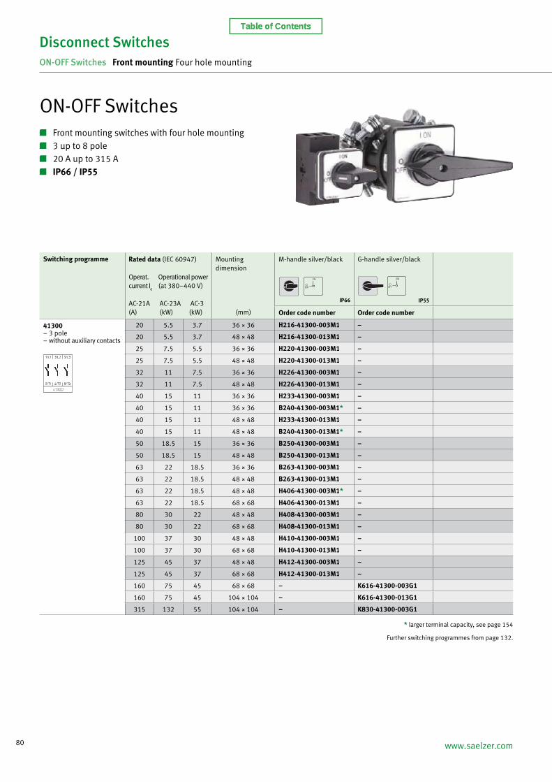
Disconnect SwitchesON-OFF Switches Front mounting Four hole mounting
Switching programme Rated data (IEC 60947)
Operat. Operational power current I
e (at 380–440 V)
AC-21A AC-23A AC-3(A) (kW) (kW)
Mountingdimension
(mm)
M-handle silver/black G-handle silver/black
Order code number Order code number
41400 – 4 pole – without auxiliary contacts – neutral contact early make/late break
20 5.5 3.7 36 × 36 H216-41400-003M1 –
20 5.5 3.7 48 × 48 H216-41400-013M1 –
25 7.5 5.5 36 × 36 H220-41400-003M1 –
25 7.5 5.5 48 × 48 H220-41400-013M1 –
32 11 7.5 36 × 36 H226-41400-003M1 –
32 11 7.5 48 × 48 H226-41400-013M1 –
40 15 11 36 × 36 H233-41400-003M1 –
40 15 11 36 × 36 B240-41400-003M1* –
40 15 11 48 × 48 H233-41400-013M1 –
40 15 11 48 × 48 B240-41400-013M1* –
50 18.5 15 36 × 36 B250-41400-003M1 –
50 18.5 15 48 × 48 B250-41400-013M1 –
63 22 18.5 36 × 36 B263-41400-003M1 –
63 22 18.5 48 × 48 B263-41400-013M1 –
63 22 18.5 48 × 48 H406-41400-003M1* –
63 22 18.5 68 × 68 H406-41400-013M1 –
80 30 22 48 × 48 H408-41400-003M1 –
80 30 22 68 × 68 H408-41400-013M1 –
100 37 30 48 × 48 H410-41400-003M1 –
100 37 30 68 × 68 H410-41400-013M1 –
125 45 37 48 × 48 H412-41400-003M1 –
125 45 37 68 × 68 H412-41400-013M1 –
160 75 45 68 × 68 – K616-41400-003G1
160 75 45 104 × 104 – K616-41400-013G1
315 132 55 104 × 104 – K830-41400-003G1
* larger terminal capacity, see page 154
Further switching programmes from page 132.
IP66 IP55
Table of Contents

82 www.saelzer.com
* larger terminal capacity, see page 154
Further switching programmes from page 132.
Switching programme Rated data (IEC 60947)
Operat. Operational power current I
e (at 380–440 V)
AC-21A AC-23A AC-3(A) (kW) (kW)
Mountingdimension
(mm)
M-handle silver/black G-handle silver/black
Order code number Order code number
41600 – 6 pole – without auxiliary contacts
20 5.5 3.7 48 × 48 H216-41600-013M1 –
25 7.5 5.5 48 × 48 H220-41600-013M1 –
32 11 7.5 48 × 48 H226-41600-013M1 –
40 15 11 48 × 48 H233-41600-013M1 –
40 15 11 48 × 48 B240-41600-013M1* –
50 18.5 15 48 × 48 B250-41600-013M1 –
63 22 18.5 48 × 48 B263-41600-013M1 –
63 22 18.5 48 × 48 H406-41600-003M1* –
63 22 18.5 68 × 68 H406-41600-013M1 –
80 30 22 48 × 48 H408-41600-003M1 –
80 30 22 68 × 68 H408-41600-013M1 –
100 37 30 48 × 48 H410-41600-003M1 –
100 37 30 68 × 68 H410-41600-013M1 –
125 45 37 48 × 48 H412-41600-003M1 –
125 45 37 68 × 68 H412-41600-013M1 –
160 75 45 68 × 68 – K616-41600-003G1
160 75 45 104 × 104 – K616-41600-013G1
315 132 55 104 × 104 – K830-41600-003G1
Disconnect SwitchesON-OFF Switches Front mounting Four hole mounting
41800 – 8 pole – without auxiliary contacts – 2 neutral contacts early make/late break
20 5.5 3.7 48 × 48 H216-41800-013M1 –
25 7.5 5.5 48 × 48 H220-41800-013M1 –
32 11 7.5 48 × 48 H226-41800-013M1 –
40 15 11 48 × 48 H233-41800-013M1 –
40 15 11 48 × 48 B240-41800-013M1* –
50 18.5 15 48 × 48 B250-41800-013M1 –
63 22 18.5 48 × 48 B263-41800-013M1 –
63 22 18.5 48 × 48 H406-41800-003M1* –
63 22 18.5 68 × 68 H406-41800-013M1 –
80 30 22 48 × 48 H408-41800-003M1 –
80 30 22 68 × 68 H408-41800-013M1 –
100 37 30 48 × 48 H410-41800-003M1 –
100 37 30 68 × 68 H410-41800-013M1 –
125 45 37 48 × 48 H412-41800-003M1 –
125 45 37 68 × 68 H412-41800-013M1 –
160 75 45 68 × 68 – K616-41800-003G1
160 75 45 104 × 104 – K616-41800-013G1
315 132 55 104 × 104 – K830-41800-003G1
IP66 IP55
Table of Contents

83
Disconnect SwitchesON-OFF Switches Front mounting Four hole mounting
Dimensions in mm:
Mtg. form A B B1 B2 C C1 D1 D2 E H
013M1 64 100 119 138 70 39 15 5 48 72
Mtg. form A B B1 B2 C C1 D1 D2 E H
003M1 64 140 159 178 86 39 15 5 48 80
013M1 88 140 159 178 86 52 15 5.5 68 80
Mtg. form A B B1 B2 C C1 D1 D2 E H
003M1 48 50 69 88 58 32 12 4.5 36 72
013M1 64 50 69 88 58 39 15 5 48 72
Mtg. form A B B1 B2 C C1 D1 D2 E H
003M1 64 70 89 108 73 39 15 5 48 80
013M1 88 70 89 108 73 52 15 5.5 68 80
Mtg. form A B B1 B2 C C1 D1 D2 E H
003M1 48 36 48 60 58 32 12 4.5 36 70
013M1 64 36 48 60 58 39 15 5 48 70
Mtg. form A B B1 B2 C C1 D1 D2 E H
013M1 64 72 84 96 66 39 15 5 48 70
Setup of order code number
Type Switching progr. Mtg. form
H406 41800 013M1
Order code no. H406-41800-013M1
* terminal lugs included
Types B240 / B250 / B263: Types B240 / B250 / B263:
Types H406 / H408 / H410 / H412:Types H406 / H408 / H410 / H412:
Switching programmes 3 and 4 pole
Types H216 / H220 / H226 / H233:
Switching programmes 6 and 8 pole
Types H216 / H220 / H226 / H233:
Switching Mtg. form progr. A C1 D* D1 D2 E L
003G1 41300 88 66 150 20 5.5 68 104
003G1 41400 88 66 150 20 5.5 68 104
013G1 41300 130 74 150 20 5.5 104 104
013G1 41400 130 74 150 20 5.5 104 104
Switching Mtg. form progr. A C1 D* D1 D2 E L
003G1 41600 88 66 150 20 5.5 68 136
003G1 41800 88 66 150 20 5.5 68 168
013G1 41600 130 74 150 20 5.5 104 136
013G1 41800 130 74 150 20 5.5 104 168
Switching Mtg. form progr. A C1 D* D1 D2 E L
003G1 41300 130 74 210 20 5.5 104 125
003G1 41400 130 74 210 20 5.5 104 125
Switching Mtg. form progr. A C1 D* D1 D2 E L
003G1 41600 130 74 210 20 5.5 104 161
003G1 41800 130 74 210 20 5.5 104 197
Type K616: Type K616:
Type K830: Type K830:
Further switching programmes and corresponding dimensions for types K on request.
Table of Contents
84 www.saelzer.com
Disconnect SwitchesON-OFF Switches Front mounting Single hole mounting
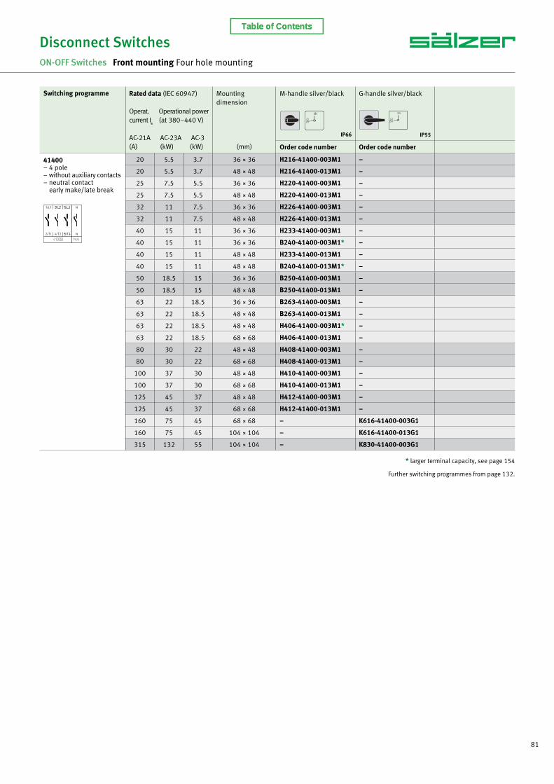
ON-OFF Switches Front mounting switches with single hole mounting 3 up to 4 pole 20 A up to 63 A IP66
Switching programme Rated data (IEC 60947)
Operat. Operational power current I
e (at 380–440 V)
AC-21A AC-23A AC-3(A) (kW) (kW)
Mountingdimension
(mm)
M-handle silver/black M-handle with front ringblack/black
Order code number Order code number
41300 – 3 pole – without auxiliary contacts
20 5.5 3.7 ∅ 22.5 H216-41300-219M1 H216-41300-218M1
20 5.5 3.7 ∅ 30.5 H216-41300-209M1 H216-41300-208M1
25 7.5 5.5 ∅ 22.5 H220-41300-219M1 H220-41300-218M1
25 7.5 5.5 ∅ 30.5 H220-41300-209M1 H220-41300-208M1
32 11 7.5 ∅ 22.5 H226-41300-219M1 H226-41300-218M1
32 11 7.5 ∅ 30.5 H226-41300-209M1 H226-41300-208M1
40 15 11 ∅ 22.5 H233-41300-219M1 H233-41300-218M1
40 15 11 ∅ 22.5 B240-41300-219M1* B240-41300-218M1*
40 15 11 ∅ 30.5 H233-41300-209M1 H233-41300-208M1
40 15 11 ∅ 30.5 B240-41300-209M1* B240-41300-208M1*
50 18.5 15 ∅ 22.5 B250-41300-219M1 B250-41300-218M1
50 18.5 15 ∅ 30.5 B250-41300-209M1 B250-41300-208M1
63 22 18.5 ∅ 22.5 B263-41300-219M1 B263-41300-218M1
63 22 18.5 ∅ 30.5 B263-41300-209M1 B263-41300-208M1
41400 – 4 pole – without auxiliary contacts – neutral contact early make/late break
20 5.5 3.7 ∅ 22.5 H216-41400-219M1 H216-41400-218M1
20 5.5 3.7 ∅ 30.5 H216-41400-209M1 H216-41400-208M1
25 7.5 5.5 ∅ 22.5 H220-41400-219M1 H220-41400-218M1
25 7.5 5.5 ∅ 30.5 H220-41400-209M1 H220-41400-208M1
32 11 7.5 ∅ 22.5 H226-41400-219M1 H226-41400-218M1
32 11 7.5 ∅ 30.5 H226-41400-209M1 H226-41400-208M1
40 15 11 ∅ 22.5 H233-41400-219M1 H233-41400-218M1
40 15 11 ∅ 22.5 B240-41400-219M1* B240-41400-218M1*
40 15 11 ∅ 30.5 H233-41400-209M1 H233-41400-208M1
40 15 11 ∅ 30.5 B240-41400-209M1* B240-41400-208M1*
50 18.5 15 ∅ 22.5 B250-41400-219M1 B250-41400-218M1
50 18.5 15 ∅ 30.5 B250-41400-209M1 B250-41400-208M1
63 22 18.5 ∅ 22.5 B263-41400-219M1 B263-41400-218M1
63 22 18.5 ∅ 30.5 B263-41400-209M1 B263-41400-208M1
* larger terminal capacity, see page 154
Further switching programmes from page 132.
IP66 IP66
Table of Contents
85
Disconnect SwitchesON-OFF Switches Front mounting Single hole mounting
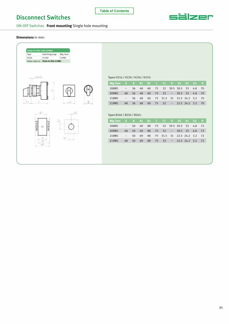
Dimensions in mm:
Mtg. form A B B1 B2 C C1 D D1 G1 G2 H
208M1 – 36 48 60 75 32 39.5 30.5 33 4.8 70
209M1 48 36 48 60 75 32 – 30.5 33 4.8 70
218M1 – 36 48 60 75 31.5 31 22.5 24.2 3.2 70
219M1 48 36 48 60 75 32 – 22.5 24.2 3.2 70
Mtg. form A B B1 B2 C C1 D D1 G1 G2 H
208M1 – 50 69 88 75 32 39.5 30.5 33 4.8 72
209M1 48 50 69 88 75 32 – 30.5 33 4.8 72
218M1 – 50 69 88 75 31.5 31 22.5 24.2 3.2 72
219M1 48 50 69 88 75 32 – 22.5 24.2 3.2 72
Setup of order code number
Type Switching progr. Mtg. form
H226 41300 219M1
Order code no. H226-41300-219M1
Types H216 / H220 / H226 / H233:
Types B240 / B250 / B263:
Table of Contents

86 www.saelzer.com
ON-OFF Switches Base mounting switches with snap-on mounting for DIN rail 3 up to 8 pole 20 A up to 125 A IP30
Disconnect SwitchesON-OFF Switches Base mounting Snap-on mounting for DIN rail
Switching programme Rated data (IEC 60947)
Operat. Operational power current I
e (at 380–440 V)
AC-21A AC-23A AC-3(A) (kW) (kW)
Escutcheon dimensionfor 45 mm aperturein Panel/Distribution boards (H × W)
(mm)
M-handle silver/black N-handle silver/grey
Order code number Order code number
41300 – 3 pole – without auxiliary contacts
20 5.5 3.7 45 × 48 H216-41300-026M1 H216-41300-026N2
20 5.5 3.7 45 × 60 H216-41300-126M1 –
25 7.5 5.5 45 × 48 H220-41300-026M1 H220-41300-026N2
25 7.5 5.5 45 × 60 H220-41300-126M1 –
32 11 7.5 45 × 48 H226-41300-026M1 H226-41300-026N2
32 11 7.5 45 × 60 H226-41300-126M1 –
40 15 11 45 × 48 H233-41300-026M1 H233-41300-026N2
40 15 11 45 × 60 H233-41300-126M1 –
40 15 11 45 × 52.5 B240-41300-026M1* B240-41300-026N2*
50 18.5 15 45 × 52.5 B250-41300-026M1 B250-41300-026N2
63 22 18.5 45 × 52.5 B263-41300-026M1 B263-41300-026N2
63 22 18.5 45 × 72 H406-41300-126M1* –
80 30 22 45 × 72 H408-41300-126M1 –
100 37 30 45 × 72 H410-41300-126M1 –
125 45 37 45 × 72 H412-41300-126M1 –
41400 – 4 pole – without auxiliary contacts – neutral contact early make/late break
20 5.5 3.7 45 × 48 H216-41400-026M1 H216-41400-026N2
20 5.5 3.7 45 × 60 H216-41400-126M1 –
25 7.5 5.5 45 × 48 H220-41400-026M1 H220-41400-026N2
25 7.5 5.5 45 × 60 H220-41400-126M1 –
32 11 7.5 45 × 48 H226-41400-026M1 H226-41400-026N2
32 11 7.5 45 × 60 H226-41400-126M1 –
40 15 11 45 × 48 H233-41400-026M1 H233-41400-026N2
40 15 11 45 × 60 H233-41400-126M1 –
40 15 11 45 × 52.5 B240-41400-026M1* B240-41400-026N2*
50 18.5 15 45 × 52.5 B250-41400-026M1 B250-41400-026N2
63 22 18.5 45 × 52.5 B263-41400-026M1 B263-41400-026N2
63 22 18.5 45 × 72 H406-41400-126M1* –
80 30 22 45 × 72 H408-41400-126M1 –
100 37 30 45 × 72 H410-41400-126M1 –
125 45 37 45 × 72 H412-41400-126M1 –
IP30 IP30
* larger terminal capacity, see page 154
Further switching programmes from page 132.
Table of Contents
87
Disconnect SwitchesON-OFF Switches Base mounting Snap-on mounting for DIN rail
Switching programme Rated data (IEC 60947)
Operat. Operational power current I
e (at 380–440 V)
AC-21A AC-23A AC-3(A) (kW) (kW)
Escutcheon dimensionfor 45 mm aperturein Panel/Distribution boards (H × W)
(mm)
M-handle silver/black
Order code number
41600 – 6 pole – without auxiliary contacts
20 5.5 3.7 45 × 76 H216-41600-026M1
25 7.5 5.5 45 × 76 H220-41600-026M1
32 11 7.5 45 × 76 H226-41600-026M1
40 15 11 45 × 76 H233-41600-026M1
40 15 11 45 × 105 B240-41600-026M1*
50 18.5 15 45 × 105 B250-41600-026M1
63 22 18.5 45 × 105 B263-41600-026M1
63 22 18.5 45 × 72 H406-41600-126M1*
80 30 22 45 × 72 H408-41600-126M1
100 37 30 45 × 72 H410-41600-126M1
125 45 37 45 × 72 H412-41600-126M1
41800 – 8 pole – without auxiliary contacts – 2 neutral contacts early make/late break
20 5.5 3.7 45 × 76 H216-41800-026M1
25 7.5 5.5 45 × 76 H220-41800-026M1
32 11 7.5 45 × 76 H226-41800-026M1
40 15 11 45 × 76 H233-41800-026M1
40 15 11 45 × 105 B240-41800-026M1*
50 18.5 15 45 × 105 B250-41800-026M1
63 22 18.5 45 × 105 B263-41800-026M1
63 22 18.5 45 × 72 H406-41800-126M1*
80 30 22 45 × 72 H408-41800-126M1
100 37 30 45 × 72 H410-41800-126M1
125 45 37 45 × 72 H412-41800-126M1
IP30
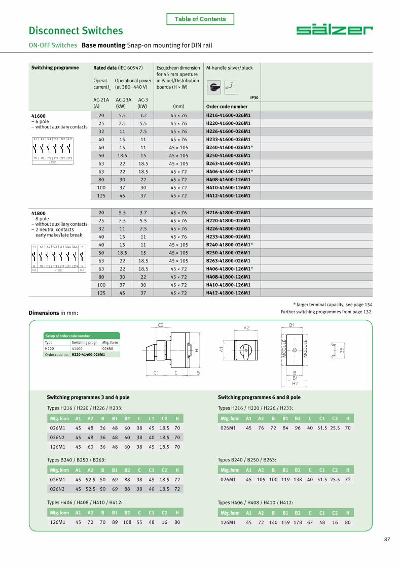
Dimensions in mm:
Setup of order code number
Type Switching progr. Mtg. form
H220 41400 026M1
Order code no. H220-41400-026M1
Mtg. form A1 A2 B B1 B2 C C1 C2 H
026M1 45 48 36 48 60 38 45 18.5 70
026N2 45 48 36 48 60 38 40 18.5 70
126M1 45 60 36 48 60 38 45 18.5 70
Mtg. form A1 A2 B B1 B2 C C1 C2 H
026M1 45 76 72 84 96 40 51.5 25.5 70
Mtg. form A1 A2 B B1 B2 C C1 C2 H
026M1 45 52.5 50 69 88 38 45 18.5 72
026N2 45 52.5 50 69 88 38 40 18.5 72
Types B240 / B250 / B263:
Mtg. form A1 A2 B B1 B2 C C1 C2 H
026M1 45 105 100 119 138 40 51.5 25.5 72
Types B240 / B250 / B263:
Types H406 / H408 / H410 / H412:
Mtg. form A1 A2 B B1 B2 C C1 C2 H
126M1 45 72 70 89 108 55 48 16 80
Types H406 / H408 / H410 / H412:
Mtg. form A1 A2 B B1 B2 C C1 C2 H
126M1 45 72 140 159 178 67 48 16 80
Types H216 / H220 / H226 / H233: Types H216 / H220 / H226 / H233:
Switching programmes 3 and 4 pole Switching programmes 6 and 8 pole
* larger terminal capacity, see page 154
Further switching programmes from page 132.
Table of Contents

88 www.saelzer.com
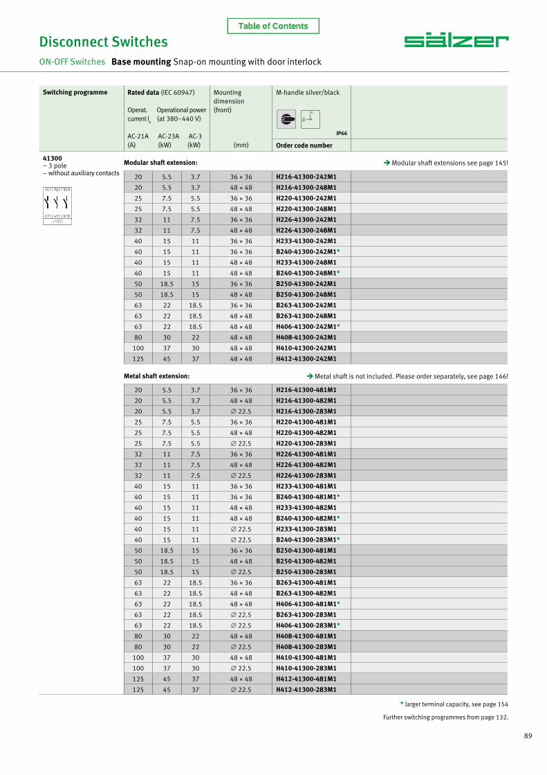
ON-OFF Switches Base mounting switches with snap-on mounting Door interlock 3 up to 8 pole 20 A up to 125 A IP66 with modular or metal shaft extension single or four hole front mounting
Disconnect SwitchesON-OFF Switches Base mounting Snap-on mounting with door interlock
Base mounting switches with snap-on mounting and door interlock are offered with two different extensions:
1. Switches with modular shaft extensions can be extended with additional modules (modular shaft extensions see picture) which can be fi xed to achieve different required mounting depths – dimension C. The modules are detailed on page 145.
2. For switches with metal shaft extension the metal shaft is not included in the scope of delivery and has to be ordered separately. Data for mounting dimension C and for the different types of metal shafts can be found on page 146.
AVC2/AVC4Modular shaft extension
AVB8Metal shaft extension forfour hole front mounting
AVA8Metal shaft extension forsingle hole front mounting
Table of Contents
89
20 5.5 3.7 36 × 36 H216-41300-481M1
20 5.5 3.7 48 × 48 H216-41300-482M1
20 5.5 3.7 ∅ 22.5 H216-41300-283M1
25 7.5 5.5 36 × 36 H220-41300-481M1
25 7.5 5.5 48 × 48 H220-41300-482M1
25 7.5 5.5 ∅ 22.5 H220-41300-283M1
32 11 7.5 36 × 36 H226-41300-481M1
32 11 7.5 48 × 48 H226-41300-482M1
32 11 7.5 ∅ 22.5 H226-41300-283M1
40 15 11 36 × 36 H233-41300-481M1
40 15 11 36 × 36 B240-41300-481M1*
40 15 11 48 × 48 H233-41300-482M1
40 15 11 48 × 48 B240-41300-482M1*
40 15 11 ∅ 22.5 H233-41300-283M1
40 15 11 ∅ 22.5 B240-41300-283M1*
50 18.5 15 36 × 36 B250-41300-481M1
50 18.5 15 48 × 48 B250-41300-482M1
50 18.5 15 ∅ 22.5 B250-41300-283M1
63 22 18.5 36 × 36 B263-41300-481M1
63 22 18.5 48 × 48 B263-41300-482M1
63 22 18.5 48 × 48 H406-41300-481M1*
63 22 18.5 ∅ 22.5 B263-41300-283M1
63 22 18.5 ∅ 22.5 H406-41300-283M1*
80 30 22 48 × 48 H408-41300-481M1
80 30 22 ∅ 22.5 H408-41300-283M1
100 37 30 48 × 48 H410-41300-481M1
100 37 30 ∅ 22.5 H410-41300-283M1
125 45 37 48 × 48 H412-41300-481M1
125 45 37 ∅ 22.5 H412-41300-283M1
Metal shaft extension:
Switching programme Rated data (IEC 60947)
Operat. Operational power current I
e (at 380–440 V)
AC-21A AC-23A AC-3(A) (kW) (kW)
Mounting dimension(front)
(mm)
M-handle silver/black
Order code number
41300 – 3 pole – without auxiliary contacts 20 5.5 3.7 36 × 36 H216-41300-242M1
20 5.5 3.7 48 × 48 H216-41300-248M1
25 7.5 5.5 36 × 36 H220-41300-242M1
25 7.5 5.5 48 × 48 H220-41300-248M1
32 11 7.5 36 × 36 H226-41300-242M1
32 11 7.5 48 × 48 H226-41300-248M1
40 15 11 36 × 36 H233-41300-242M1
40 15 11 36 × 36 B240-41300-242M1*
40 15 11 48 × 48 H233-41300-248M1
40 15 11 48 × 48 B240-41300-248M1*
50 18.5 15 36 × 36 B250-41300-242M1
50 18.5 15 48 × 48 B250-41300-248M1
63 22 18.5 36 × 36 B263-41300-242M1
63 22 18.5 48 × 48 B263-41300-248M1
63 22 18.5 48 × 48 H406-41300-242M1*
80 30 22 48 × 48 H408-41300-242M1
100 37 30 48 × 48 H410-41300-242M1
125 45 37 48 × 48 H412-41300-242M1
Modular shaft extension:
Metal shaft is not included. Please order separately, see page 146!
Modular shaft extensions see page 145!
Disconnect SwitchesON-OFF Switches Base mounting Snap-on mounting with door interlock
* larger terminal capacity, see page 154
Further switching programmes from page 132.
IP66
Table of Contents

90 www.saelzer.com
20 5.5 3.7 36 × 36 H216-41400-481M1
20 5.5 3.7 48 × 48 H216-41400-482M1
20 5.5 3.7 ∅ 22.5 H216-41400-283M1
25 7.5 5.5 36 × 36 H220-41400-481M1
25 7.5 5.5 48 × 48 H220-41400-482M1
25 7.5 5.5 ∅ 22.5 H220-41400-283M1
32 11 7.5 36 × 36 H226-41400-481M1
32 11 7.5 48 × 48 H226-41400-482M1
32 11 7.5 ∅ 22.5 H226-41400-283M1
40 15 11 36 × 36 H233-41400-481M1
40 15 11 36 × 36 B240-41400-481M1*
40 15 11 48 × 48 H233-41400-482M1
40 15 11 48 × 48 B240-41400-482M1*
40 15 11 ∅ 22.5 H233-41400-283M1
40 15 11 ∅ 22.5 B240-41400-283M1*
50 18.5 15 36 × 36 B250-41400-481M1
50 18.5 15 48 × 48 B250-41400-482M1
50 18.5 15 ∅ 22.5 B250-41400-283M1
63 22 18.5 36 × 36 B263-41400-481M1
63 22 18.5 48 × 48 B263-41400-482M1
63 22 18.5 48 × 48 H406-41400-481M1*
63 22 18.5 ∅ 22.5 B263-41400-283M1
63 22 18.5 ∅ 22.5 H406-41400-283M1*
80 30 22 48 × 48 H408-41400-481M1
80 30 22 ∅ 22.5 H408-41400-283M1
100 37 30 48 × 48 H410-41400-481M1
100 37 30 ∅ 22.5 H410-41400-283M1
125 45 37 48 × 48 H412-41400-481M1
125 45 37 ∅ 22.5 H412-41400-283M1
Metal shaft extension:
Switching programme Rated data (IEC 60947)
Operat. Operational power current I
e (at 380–440 V)
AC-21A AC-23A AC-3(A) (kW) (kW)
Mounting dimension(front)
(mm)
M-handle silver/black
Order code number
41400 – 4 pole – without auxiliary contacts – neutral contact early make/late break
20 5.5 3.7 36 × 36 H216-41400-242M1
20 5.5 3.7 48 × 48 H216-41400-248M1
25 7.5 5.5 36 × 36 H220-41400-242M1
25 7.5 5.5 48 × 48 H220-41400-248M1
32 11 7.5 36 × 36 H226-41400-242M1
32 11 7.5 48 × 48 H226-41400-248M1
40 15 11 36 × 36 H233-41400-242M1
40 15 11 36 × 36 B240-41400-242M1*
40 15 11 48 × 48 H233-41400-248M1
40 15 11 48 × 48 B240-41400-248M1*
50 18.5 15 36 × 36 B250-41400-242M1
50 18.5 15 48 × 48 B250-41400-248M1
63 22 18.5 36 × 36 B263-41400-242M1
63 22 18.5 48 × 48 B263-41400-248M1
63 22 18.5 48 × 48 H406-41400-242M1*
80 30 22 48 × 48 H408-41400-242M1
100 37 30 48 × 48 H410-41400-242M1
125 45 37 48 × 48 H412-41400-242M1
Modular shaft extension:
Metal shaft is not included. Please order separately, see page 146!
Modular shaft extensions see page 145!
Disconnect SwitchesON-OFF Switches Base mounting Snap-on mounting with door interlock
* larger terminal capacity, see page 154
Further switching programmes from page 132.
IP66
Table of Contents

91
20 5.5 3.7 48 × 48 H216-41600-482M1
20 5.5 3.7 ∅ 22.5 H216-41600-285M1
25 7.5 5.5 48 × 48 H220-41600-482M1
25 7.5 5.5 ∅ 22.5 H220-41600-285M1
32 11 7.5 48 × 48 H226-41600-482M1
32 11 7.5 ∅ 22.5 H226-41600-285M1
40 15 11 48 × 48 H233-41600-482M1
40 15 11 48 × 48 B240-41600-482M1*
40 15 11 ∅ 22.5 H233-41600-285M1
40 15 11 ∅ 22.5 B240-41600-285M1*
50 18.5 15 48 × 48 B250-41600-482M1
50 18.5 15 ∅ 22.5 B250-41600-285M1
63 22 18.5 48 × 48 B263-41600-482M1
63 22 18.5 48 × 48 H406-41600-481M1*
63 22 18.5 ∅ 22.5 B263-41600-285M1
63 22 18.5 ∅ 22.5 H406-41600-283M1*
80 30 22 48 × 48 H408-41600-481M1
80 30 22 ∅ 22.5 H408-41600-283M1
100 37 30 48 × 48 H410-41600-481M1
100 37 30 ∅ 22.5 H410-41600-283M1
125 45 37 48 × 48 H412-41600-481M1
125 45 37 ∅ 22.5 H412-41600-283M1
Metal shaft extension:
Switching programme Rated data (IEC 60947)
Operat. Operational power current I
e (at 380–440 V)
AC-21A AC-23A AC-3(A) (kW) (kW)
Mounting dimension(front)
(mm)
M-handle silver/black
Order code number
41600 – 6 pole – without auxiliary contacts
20 5.5 3.7 48 × 48 H216-41600-248M1
25 7.5 5.5 48 × 48 H220-41600-248M1
32 11 7.5 48 × 48 H226-41600-248M1
40 15 11 48 × 48 H233-41600-248M1
40 15 11 48 × 48 B240-41600-248M1*
50 18.5 15 48 × 48 B250-41600-248M1
63 22 18.5 48 × 48 B263-41600-248M1
63 22 18.5 48 × 48 H406-41600-242M1*
80 30 22 48 × 48 H408-41600-242M1
100 37 30 48 × 48 H410-41600-242M1
125 45 37 48 × 48 H412-41600-242M1
Modular shaft extension:
Metal shaft is not included. Please order separately, see page 146!
Modular shaft extensions see page 145!
Disconnect SwitchesON-OFF Switches Base mounting Snap-on mounting with door interlock
* larger terminal capacity, see page 154
Further switching programmes from page 132.
IP66
Table of Contents

92 www.saelzer.com
20 5.5 3.7 48 × 48 H216-41800-482M1
20 5.5 3.7 ∅ 22.5 H216-41800-285M1
25 7.5 5.5 48 × 48 H220-41800-482M1
25 7.5 5.5 ∅ 22.5 H220-41800-285M1
32 11 7.5 48 × 48 H226-41800-482M1
32 11 7.5 ∅ 22.5 H226-41800-285M1
40 15 11 48 × 48 H233-41800-482M1
40 15 11 48 × 48 B240-41800-482M1*
40 15 11 ∅ 22.5 H233-41800-285M1
40 15 11 ∅ 22.5 B240-41800-285M1*
50 18.5 15 48 × 48 B250-41800-482M1
50 18.5 15 ∅ 22.5 B250-41800-285M1
63 22 18.5 48 × 48 B263-41800-482M1
63 22 18.5 48 × 48 H406-41800-481M1*
63 22 18.5 ∅ 22.5 B263-41800-285M1
63 22 18.5 ∅ 22.5 H406-41800-283M1*
80 30 22 48 × 48 H408-41800-481M1
80 30 22 ∅ 22.5 H408-41800-283M1
100 37 30 48 × 48 H410-41800-481M1
100 37 30 ∅ 22.5 H410-41800-283M1
125 45 37 48 × 48 H412-41800-481M1
125 45 37 ∅ 22.5 H412-41800-283M1
Metal shaft extension:
Switching programme Rated data (IEC 60947)
Operat. Operational power current I
e (at 380–440 V)
AC-21A AC-23A AC-3(A) (kW) (kW)
Mounting dimension(front)
(mm)
M-handle silver/black
Order code number
41800 – 8 pole – without auxiliary contacts – 2 neutral contacts early make/late break
20 5.5 3.7 48 × 48 H216-41800-248M1
25 7.5 5.5 48 × 48 H220-41800-248M1
32 11 7.5 48 × 48 H226-41800-248M1
40 15 11 48 × 48 H233-41800-248M1
40 15 11 48 × 48 B240-41800-248M1*
50 18.5 15 48 × 48 B250-41800-248M1
63 22 18.5 48 × 48 B263-41800-248M1
63 22 18.5 48 × 48 H406-41800-242M1*
80 30 22 48 × 48 H408-41800-242M1
100 37 30 48 × 48 H410-41800-242M1
125 45 37 48 × 48 H412-41800-242M1
Modular shaft extension:
Metal shaft is not included. Please order separately, see page 146!
Modular shaft extensions see page 145!
Disconnect SwitchesON-OFF Switches Base mounting Snap-on mounting with door interlock
* larger terminal capacity, see page 154
Further switching programmes from page 132.
IP66
Table of Contents
93
Disconnect SwitchesON-OFF Switches Base mounting Snap-on mounting with door interlock
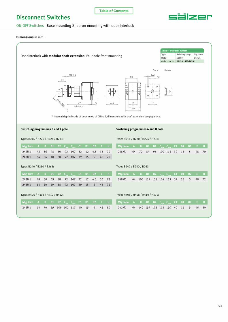
Dimensions in mm:
Switching programmes 3 and 4 pole
Types H216 / H220 / H226 / H233:
Mtg. form A B B1 B2 Cmin Cmax C1 D1 D2 E H
242M1 48 36 48 60 92 107 32 12 4.5 36 70
248M1 64 36 48 60 92 107 39 15 5 48 70
Switching programmes 6 and 8 pole
Types H216 / H220 / H226 / H233:
Mtg. form A B B1 B2 Cmin Cmax C1 D1 D2 E H
248M1 64 72 84 96 100 115 39 15 5 48 70
Types B240 / B250 / B263:
Mtg. form A B B1 B2 Cmin Cmax C1 D1 D2 E H
242M1 48 50 69 88 92 107 32 12 4.5 36 72
248M1 64 50 69 88 92 107 39 15 5 48 72
Types B240 / B250 / B263:
Mtg. form A B B1 B2 Cmin Cmax C1 D1 D2 E H
248M1 64 100 119 138 104 119 39 15 5 48 72
Types H406 / H408 / H410 / H412:
Mtg. form A B B1 B2 Cmin Cmax C1 D1 D2 E H
242M1 64 70 89 108 102 117 40 15 5 48 80
Types H406 / H408 / H410 / H412:
Mtg. form A B B1 B2 Cmin Cmax C1 D1 D2 E H
242M1 64 140 159 178 115 130 40 15 5 48 80
Door interlock with modular shaft extension: Four hole front mounting
Setup of order code number
Type Switching progr. Mtg. form
H412 41800 242M1
Order code no. H412-41800-242M1
1) Internal depth: inside of door to top of DIN rail, dimensions with shaft extension see page 145.
Table of Contents
94 www.saelzer.com
Disconnect SwitchesON-OFF Switches Base mounting Snap-on mounting with door interlock
Dimensions in mm:
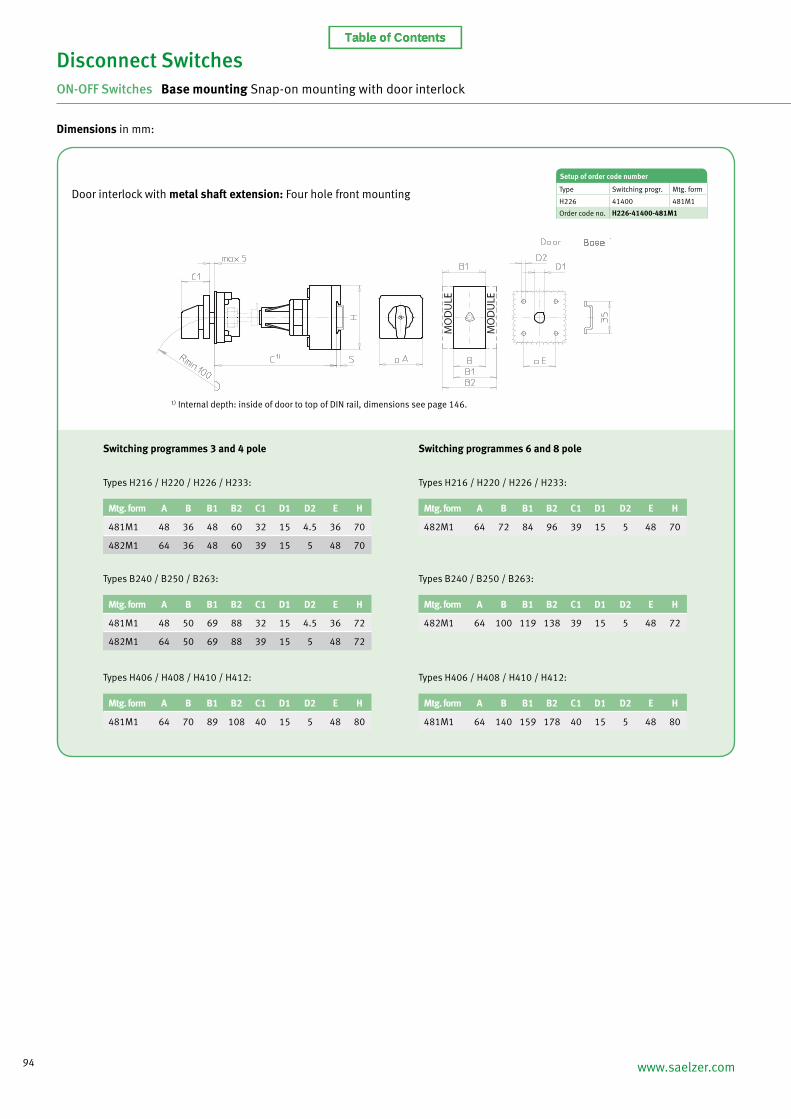
Switching programmes 3 and 4 pole
Types H216 / H220 / H226 / H233:
Mtg. form A B B1 B2 C1 D1 D2 E H
481M1 48 36 48 60 32 15 4.5 36 70
482M1 64 36 48 60 39 15 5 48 70
Setup of order code number
Type Switching progr. Mtg. form
H226 41400 481M1
Order code no. H226-41400-481M1
Switching programmes 6 and 8 pole
Types H216 / H220 / H226 / H233:
Mtg. form A B B1 B2 C1 D1 D2 E H
482M1 64 72 84 96 39 15 5 48 70
Types B240 / B250 / B263:
Mtg. form A B B1 B2 C1 D1 D2 E H
481M1 48 50 69 88 32 15 4.5 36 72
482M1 64 50 69 88 39 15 5 48 72
Types B240 / B250 / B263:
Mtg. form A B B1 B2 C1 D1 D2 E H
482M1 64 100 119 138 39 15 5 48 72
Types H406 / H408 / H410 / H412:
Mtg. form A B B1 B2 C1 D1 D2 E H
481M1 64 70 89 108 40 15 5 48 80
Types H406 / H408 / H410 / H412:
Mtg. form A B B1 B2 C1 D1 D2 E H
481M1 64 140 159 178 40 15 5 48 80
Door interlock with metal shaft extension: Four hole front mounting
1) Internal depth: inside of door to top of DIN rail, dimensions see page 146.
Table of Contents

95
Dimensions in mm:
Switching programmes 3 and 4 pole
Types H216 / H220 / H226 / H233:
Mtg. form A B B1 B2 C1 D1 G1 G2 H
283M1 48 36 48 60 32 22.5 24.2 3.2 70
Switching programmes 6 and 8 pole
Types H216 / H220 / H226 / H233:
Mtg. form A B B1 B2 C1 D1 G1 G2 H
285M1 64 72 84 96 39 22.5 24.2 3.2 70
Types B240 / B250 / B263:
Mtg. form A B B1 B2 C1 D1 G1 G2 H
283M1 48 50 69 88 32 22.5 24.2 3.2 72
Types B240 / B250 / B263:
Mtg. form A B B1 B2 C1 D1 G1 G2 H
285M1 64 100 119 138 39 22.5 24.2 3.2 72
Types H406 / H408 / H410 / H412:
Mtg. form A B B1 B2 C1 D1 G1 G2 H
283M1 64 70 89 108 39 22.5 24.2 3.2 80
Types H406 / H408 / H410 / H412:
Mtg. form A B B1 B2 C1 D1 G1 G2 H
283M1 64 140 159 178 39 22.5 24.2 3.2 80
Door interlock with metal shaft extension: Single hole front mounting
1) Internal depth: outside of door to top of DIN rail, dimensions see page 146.
Disconnect SwitchesON-OFF Switches Base mounting Snap-on mounting with door interlock
Setup of order code number
Type Switching progr. Mtg. form
B250 41400 283M1
Order code no. B250-41400-283M1
Table of Contents

96 www.saelzer.com
ON-OFF Switches Base mounting switches with four hole mounting
and door interlock 3 up to 8 pole 160 A up to 315 A IP55
Disconnect SwitchesON-OFF Switches Base mounting Four hole mounting with door interlock
Switching programme Rated data (IEC 60947)
Operat. Operational power current I
e (at 380–440 V)
AC-21A AC-23A AC-3(A) (kW) (kW)
Mountingdimension (base/front)
(mm)
G-handle silver/black
Order code number
41300 – 3 pole – without auxiliary contacts
160 75 45 68 × 68 / 68 × 68 K616-41300-042G1
315 132 55 104 × 104 / 104 × 104 K830-41300-042G1
41400 – 4 pole – without auxiliary contacts – neutral contact early make/late break
160 75 45 68 × 68 / 68 × 68 K616-41400-042G1
315 132 55 104 × 104 / 104 × 104 K830-41400-042G1
41600 – 6 pole – without auxiliary contacts
160 75 45 68 × 68 / 68 × 68 K616-41600-042G1
315 132 55 104 × 104 / 104 × 104 K830-41600-042G1
41800 – 8 pole – without auxiliary contacts – 2 neutral contacts early make/late break
160 75 45 68 × 68 / 68 × 68 K616-41800-042G1
315 132 55 104 × 104 / 104 × 104 K830-41800-042G1
IP55
Table of Contents

97
Disconnect SwitchesON-OFF Switches Base mounting Four hole mounting with door interlock
Dimensions in mm:
Switching progr. A C1 D* D1 D2 E min max L
41300 88 66 150 15 5.5 68 48 60 104
41400 88 66 150 15 5.5 68 48 60 104
41600 88 66 150 15 5.5 68 48 60 136
41800 88 66 150 15 5.5 68 48 60 168
Setup of order code number
Type Switching progr. Mtg. form
K830 41300 042G1
Order code no. K830-41300-042G1
Switching progr. A C1 D* D1 D2 E min max L
41300 130 74 210 20 5.5 104 75 102 125
41400 130 74 210 20 5.5 104 75 102 125
41600 130 74 210 20 5.5 104 75 102 161
41800 130 74 210 20 5.5 104 75 102 197
* terminal lugs included
Type K830:
Type K616:
Further switching programmes and corresponding dimensions for types K on request.
Table of Contents

98 www.saelzer.com
ON-OFF Switches Enclosed switches with insulated enclosure (polycarbonate) Cover interlock in ON position 3 up to 8 pole 20 A up to 125 A IP66
Switching programme Rated data (IEC 60947)
Operat. Operational power current I
e (at 380–440 V)
AC-21A AC-23A AC-3(A) (kW) (kW)
Enclosuredimension(H × W × D)
(mm)
M-handle silver/black
Order code number
41300 – 3 pole – without auxiliary contacts
20 5.5 3.7 125 × 100 × 85 H216-41300-701M1
20 5.5 3.7 175 × 115 × 100 H216-41300-711M1
20 5.5 3.7 250 × 160 × 120 H216-41300-731M1
25 7.5 5.5 125 × 100 × 85 H220-41300-701M1
25 7.5 5.5 175 × 115 × 100 H220-41300-711M1
25 7.5 5.5 250 × 160 × 120 H220-41300-731M1
32 11 7.5 125 × 100 × 85 H226-41300-701M1
32 11 7.5 175 × 115 × 100 H226-41300-711M1
32 11 7.5 250 × 160 × 120 H226-41300-731M1
40 15 11 175 × 115 × 100 H233-41300-711M1
40 15 11 175 × 115 × 100 B240-41300-711M1* 1
40 15 11 250 × 160 × 120 H233-41300-731M1
40 15 11 250 × 160 × 120 B240-41300-731M1*
50 18.5 15 175 × 115 × 100 B250-41300-711M1 1
50 18.5 15 250 × 160 × 120 B250-41300-731M1
63 22 18.5 175 × 115 × 100 B263-41300-711M1 1
63 22 18.5 250 × 160 × 120 B263-41300-731M1
63 22 18.5 250 × 160 × 120 H406-41300-731M1*
63 22 18.5 280 × 190 × 130 H406-41300-771M1
63 22 18.5 320 × 220 × 180 H406-41300-476M1
80 30 22 250 × 160 × 120 H408-41300-731M1
80 30 22 280 × 190 × 130 H408-41300-771M1
80 30 22 320 × 220 × 180 H408-41300-476M1
100 37 30 250 × 160 × 120 H410-41300-731M1
100 37 30 280 × 190 × 130 H410-41300-771M1
100 37 30 320 × 220 × 180 H410-41300-476M1
125 45 37 320 × 220 × 180 H412-41300-476M1
Disconnect SwitchesON-OFF Switches Enclosed Switches – Insulated Enclosure
* larger terminal capacity, see page 154
1 Terminal capacity max. 16 mm2 on N-terminal and/or PE-terminal
Further switching programmes from page 132.
IP66
Table of Contents

99
Switching programme Rated data (IEC 60947)
Operat. Operational power current I
e (at 380–440 V)
AC-21A AC-23A AC-3(A) (kW) (kW)
Enclosuredimension(H × W × D)
(mm)
M-handle silver/black
Order code number
41400 – 4 pole – without auxiliary contacts – neutral contact early make/late break
20 5.5 3.7 125 × 100 × 85 H216-41400-701M1
20 5.5 3.7 175 × 115 × 100 H216-41400-711M1
20 5.5 3.7 250 × 160 × 120 H216-41400-731M1
25 7.5 5.5 125 × 100 × 85 H220-41400-701M1
25 7.5 5.5 175 × 115 × 100 H220-41400-711M1
25 7.5 5.5 250 × 160 × 120 H220-41400-731M1
32 11 7.5 125 × 100 × 85 H226-41400-701M1
32 11 7.5 175 × 115 × 100 H226-41400-711M1
32 11 7.5 250 × 160 × 120 H226-41400-731M1
40 15 11 175 × 115 × 100 H233-41400-711M1
40 15 11 175 × 115 × 100 B240-41400-711M1* 1
40 15 11 250 × 160 × 120 H233-41400-731M1
40 15 11 250 × 160 × 120 B240-41400-731M1*
50 18.5 15 175 × 115 × 100 B250-41400-711M1 1
50 18.5 15 250 × 160 × 120 B250-41400-731M1
63 22 18.5 175 × 115 × 100 B263-41400-711M1 1
63 22 18.5 250 × 160 × 120 B263-41400-731M1
63 22 18.5 250 × 160 × 120 H406-41400-731M1*
63 22 18.5 280 × 190 × 130 H406-41400-771M1
63 22 18.5 320 × 220 × 180 H406-41400-476M1
80 30 22 250 × 160 × 120 H408-41400-731M1
80 30 22 280 × 190 × 130 H408-41400-771M1
80 30 22 320 × 220 × 180 H408-41400-476M1
100 37 30 250 × 160 × 120 H410-41400-731M1
100 37 30 280 × 190 × 130 H410-41400-771M1
100 37 30 320 × 220 × 180 H410-41400-476M1
125 45 37 320 × 220 × 180 H412-41400-476M1
Disconnect SwitchesON-OFF Switches Enclosed Switches – Insulated Enclosure
* larger terminal capacity, see page 154
1 Terminal capacity max. 16 mm2 on N-terminal and/or PE-terminal
Further switching programmes from page 132.
IP66
Table of Contents

100 www.saelzer.com
Switching programme Rated data (IEC 60947)
Operat. Operational power current I
e (at 380–440 V)
AC-21A AC-23A AC-3(A) (kW) (kW)
Enclosuredimension(H × W × D)
(mm)
M-handle silver/black
Order code number
41600 – 6 pole – without auxiliary contacts
20 5.5 3.7 175 × 115 × 100 H216-41600-721M1
20 5.5 3.7 250 × 160 × 120 H216-41600-734M1
20 5.5 3.7 280 × 190 × 130 H216-41600-771M1
25 7.5 5.5 175 × 115 × 100 H220-41600-721M1
25 7.5 5.5 250 × 160 × 120 H220-41600-734M1
25 7.5 5.5 280 × 190 × 130 H220-41600-771M1
32 11 7.5 175 × 115 × 100 H226-41600-721M1
32 11 7.5 250 × 160 × 120 H226-41600-734M1
32 11 7.5 280 × 190 × 130 H226-41600-771M1
40 15 11 175 × 115 × 100 H233-41600-721M1
40 15 11 250 × 160 × 120 H233-41600-734M1
40 15 11 280 × 190 × 130 H233-41600-771M1
40 15 11 280 × 190 × 130 B240-41600-771M1* 1
40 15 11 320 × 220 × 180 B240-41600-976M1
50 18.5 15 280 × 190 × 130 B250-41600-771M1 1
50 18.5 15 320 × 220 × 180 B250-41600-976M1
63 22 18.5 280 × 190 × 130 B263-41600-771M1 1
63 22 18.5 320 × 220 × 180 B263-41600-976M1
63 22 18.5 440 × 320 × 180 H406-41600-578M1
80 30 22 440 × 320 × 180 H408-41600-578M1
100 37 30 440 × 320 × 180 H410-41600-578M1
125 45 37 440 × 320 × 180 H412-41600-578M1
Disconnect SwitchesON-OFF Switches Enclosed Switches – Insulated Enclosure
41800 – 8 pole – without auxiliary contacts – 2 neutral contacts early make/late break
20 5.5 3.7 250 × 160 × 120 H216-41800-734M1
20 5.5 3.7 280 × 190 × 130 H216-41800-771M1
25 7.5 5.5 250 × 160 × 120 H220-41800-734M1
25 7.5 5.5 280 × 190 × 130 H220-41800-771M1
32 11 7.5 250 × 160 × 120 H226-41800-734M1
32 11 7.5 280 × 190 × 130 H226-41800-771M1
40 15 11 250 × 160 × 120 H233-41800-734M1
40 15 11 280 × 190 × 130 H233-41800-771M1
40 15 11 280 × 190 × 130 B240-41800-771M1*
40 15 11 320 × 220 × 180 B240-41800-976M1
50 18.5 15 280 × 190 × 130 B250-41800-771M1
50 18.5 15 320 × 220 × 180 B250-41800-976M1
63 22 18.5 280 × 190 × 130 B263-41800-771M1
63 22 18.5 320 × 220 × 180 B263-41800-976M1
63 22 18.5 440 × 320 × 180 H406-41800-578M1
80 30 22 440 × 320 × 180 H408-41800-578M1
100 37 30 440 × 320 × 180 H410-41800-578M1
125 45 37 440 × 320 × 180 H412-41800-578M1
* larger terminal capacity, see page 154
1 Terminal capacity max. 16 mm2 on N-terminal and/or PE-terminal
Further switching programmes from page 132.
IP66
Table of Contents

101
Disconnect SwitchesON-OFF Switches Enclosed Switches – Insulated Enclosure
Setup of order code number
Type Switching progr. Mtg. form
B250 41400 711M1
Order code no. B250-41400-711M1
Dimensions in mm:
Insulated enclosures 125 × 100 × 85 mmand 175 × 115 × 100 mm:
Mtg. form H1 B1 T1 T2 2×M H2
701M1 125 100 85 32 20/25 115
711M1 175 115 100 39 20/25 165
721M1 175 115 100 39 20/25 165
Mtg. form H1 B1 T1 T2 2×M H2
731M1 250 160 120 39 32/40 235
734M1 250 160 120 39 32/40 235
Insulated enclosure 250 × 160 × 120 mm:
Insulated enclosure 280 × 190 × 130 mm:
Mtg. form H1 B1 T1 T2 2×M H2 B2
771M1 280 190 130 39 40×1.5 254 164
Mtg. form H1 B1 T1 T2 2×M H2 B2
771M1 280 190 130 39 40×1.5 254 164
Mtg. form H1 B1 T1 T2 2×M H2 B2
771M1 280 190 130 52 40×1.5 254 164
Types H216 / H220 / H226 / H233:
Types B240 / B250 / B263:
Types H406 / H408 / H410 / H412:
Types H216 / H220 / H226 / H233 / B240 / B250 / B263:
Types H216 / H220 / H226 / H233 / B240 / B250 / B263 /
H406 / H408 / H410 / H412:
Table of Contents

102 www.saelzer.com
Disconnect SwitchesON-OFF Switches Enclosed Switches – Insulated Enclosure
Dimensions in mm:
Setup of order code number
Type Switching progr. Mtg. form
H406 41600 578M1
Order code no. H406-41600-578M1
Insulated enclosure 320 × 220 × 180 mm:
Insulated enclosure 440 × 320 × 180 mm:
Mtg. form H1 B1 T1 T2 2×M H2 B2
476M1 320 220 180 52 501 293 193
976M1 320 220 180 52 –2 293 193
Mtg. form H1 B1 T1 T2 H2 B2
578M1 440 320 180 52 480 293
Blank gland plates
Mounting brackets are included.
1 Gland plates with knockouts2 Blank gland plates
Types B240 / B250 / B263 / H406 / H408 / H410 / H412:
Types H406 / H408 / H410 / H412:
Table of Contents

103
ON-OFF Switches Enclosed switches with insulated enclosure (polycarbonate) EMV/EMC application, connection system for the uninterrupted
connection of shielded/screened cables consisting of shroud and 4 shroud clamps ∅ 12–16 mm
Cover interlock in ON position 3 up to 6 pole 20 A up to 63 A IP66
Disconnect SwitchesON-OFF Switches Enclosed Switches – Insulated Enclosure for EMV/EMC application
Switching programme Rated data (IEC 60947)
Operat. Operational power current I
e (at 380–440 V)
AC-21A AC-23A AC-3(A) (kW) (kW)
Enclosuredimension(H × W × D)
(mm)
M-handle silver/black
Order code number
41300 – 3 pole – without auxiliary contacts
20 5.5 3.7 175 × 115 × 100 H216-41300-716M1
25 7.5 5.5 175 × 115 × 100 H220-41300-716M1
32 11 7.5 175 × 115 × 100 H226-41300-716M1
40 15 11 175 × 115 × 100 H233-41300-716M1
40 15 11 175 × 115 × 100 B240-41300-716M1*
50 18.5 15 175 × 115 × 100 B250-41300-716M1
63 22 18.5 175 × 115 × 100 B263-41300-716M1
* larger terminal capacity, see page 154
41400 – 4 pole – without auxiliary contacts – neutral contact early make/late break
20 5.5 3.7 175 × 115 × 100 H216-41400-716M1
25 7.5 5.5 175 × 115 × 100 H220-41400-716M1
32 11 7.5 175 × 115 × 100 H226-41400-716M1
40 15 11 175 × 115 × 100 H233-41400-716M1
40 15 11 175 × 115 × 100 B240-41400-716M1*
50 18.5 15 175 × 115 × 100 B250-41400-716M1
63 22 18.5 175 × 115 × 100 B263-41400-716M1
41600 – 6 pole – without auxiliary contacts
20 5.5 3.7 175 × 115 × 100 H216-41600-726M1
25 7.5 5.5 175 × 115 × 100 H220-41600-726M1
32 11 7.5 175 × 115 × 100 H226-41600-726M1
40 15 11 175 × 115 × 100 H233-41600-726M1
Further switching programmes from page 132.Dimensions in mm:
Mtg. form H1 B1 T1 T2 2×M H2
716M1 175 115 100 39 20/25 165
726M1 175 115 100 39 20/25 165
Types H216 / H220 / H226 / H233 / B240 / B250 / B263:
IP66
Table of Contents

104 www.saelzer.com
ON-OFF Switches Enclosed switches with mild steel enclosure (powder coated – RAL 7035) Cover interlock in ON position 3 up to 8 pole 20 A up to 125 A IP66
Switching programme Rated data (IEC 60947)
Operat. Operational power current I
e (at 380–440 V)
AC-21A AC-23A AC-3(A) (kW) (kW)
Enclosuredimension(H × W × D)
(mm)
M-handle silver/black
Order code number
41300 – 3 pole – without auxiliary contacts
20 5.5 3.7 150 × 150 × 120 H216-41300-086M1
20 5.5 3.7 200 × 150 × 120 H216-41300-186M1
25 7.5 5.5 150 × 150 × 120 H220-41300-086M1
25 7.5 5.5 200 × 150 × 120 H220-41300-186M1
32 11 7.5 150 × 150 × 120 H226-41300-086M1
32 11 7.5 200 × 150 × 120 H226-41300-186M1
40 15 11 200 × 150 × 120 H233-41300-186M1
40 15 11 200 × 150 × 120 B240-41300-086M1*
50 18.5 15 200 × 150 × 120 B250-41300-086M1
63 22 18.5 200 × 150 × 120 B263-41300-086M1
63 22 18.5 200 × 150 × 120 H406-41300-986M1*
63 22 18.5 300 × 250 × 150 H406-41300-186M1
63 22 18.5 400 × 300 × 155 H406-41300-181M1 1
80 30 22 200 × 150 × 120 H408-41300-986M1
80 30 22 300 × 250 × 150 H408-41300-186M1
80 30 22 400 × 300 × 155 H408-41300-181M1 1
100 37 30 300 × 250 × 150 H410-41300-186M1
100 37 30 400 × 300 × 155 H410-41300-181M1 1
125 45 37 300 × 250 × 150 H412-41300-186M1
125 45 37 400 × 300 × 155 H412-41300-181M1 1
Disconnect SwitchesON-OFF Switches Enclosed Switches – Mild Steel Enclosure
* larger terminal capacity, see page 1541 hinged door
Further switching programmes from page 132.
IP66
Table of Contents

105
Disconnect SwitchesON-OFF Switches Enclosed Switches – Mild Steel Enclosure
Switching programme Rated data (IEC 60947)
Operat. Operational power current I
e (at 380–440 V)
AC-21A AC-23A AC-3(A) (kW) (kW)
Mountingdimension
(mm)
M-handle silver/black
Order code number
41400 – 4 pole – without auxiliary contacts – neutral contact early make/late break
20 5.5 3.7 150 × 150 × 120 H216-41400-086M1
20 5.5 3.7 200 × 150 × 120 H216-41400-186M1
25 7.5 5.5 150 × 150 × 120 H220-41400-086M1
25 7.5 5.5 200 × 150 × 120 H220-41400-186M1
32 11 7.5 150 × 150 × 120 H226-41400-086M1
32 11 7.5 200 × 150 × 120 H226-41400-186M1
40 15 11 200 × 150 × 120 H233-41400-186M1
40 15 11 200 × 150 × 120 B240-41400-086M1*
50 18.5 15 200 × 150 × 120 B250-41400-086M1
63 22 18.5 200 × 150 × 120 B263-41400-086M1
63 22 18.5 200 × 150 × 120 H406-41400-986M1*
63 22 18.5 300 × 250 × 150 H406-41400-186M1
63 22 18.5 400 × 300 × 155 H406-41400-181M1 1
80 30 22 200 × 150 × 120 H408-41400-986M1
80 30 22 300 × 250 × 150 H408-41400-186M1
80 30 22 400 × 300 × 155 H408-41400-181M1 1
100 37 30 300 × 250 × 150 H410-41400-186M1
100 37 30 400 × 300 × 155 H410-41400-181M1 1
125 45 37 300 × 250 × 150 H412-41400-186M1
125 45 37 400 × 300 × 155 H412-41400-181M1 1
41600 – 6 pole – without auxiliary contacts
20 5.5 3.7 200 × 150 × 120 H216-41600-186M1
25 7.5 5.5 200 × 150 × 120 H220-41600-186M1
32 11 7.5 200 × 150 × 120 H226-41600-186M1
40 15 11 200 × 150 × 120 H233-41600-186M1
40 15 11 300 × 250 × 150 B240-41600-186M1
50 18.5 15 300 × 250 × 150 B250-41600-186M1
63 22 18.5 300 × 250 × 150 B263-41600-186M1
63 22 18.5 300 × 250 × 150 H406-41600-186M1*
63 22 18.5 400 × 300 × 155 H406-41600-181M1 1
80 30 22 300 × 250 × 150 H408-41600-186M1
80 30 22 400 × 300 × 155 H408-41600-181M1 1
100 37 30 300 × 250 × 150 H410-41600-186M1
100 37 30 400 × 300 × 155 H410-41600-181M1 1
125 45 37 300 × 250 × 150 H412-41600-186M1
125 45 37 400 × 300 × 155 H412-41600-181M1 1
41800 – 8 pole – without auxiliary contacts – 2 neutral contacts early make/late break
20 5.5 3.7 200 × 150 × 120 H216-41800-186M1
25 7.5 5.5 200 × 150 × 120 H220-41800-186M1
32 11 7.5 200 × 150 × 120 H226-41800-186M1
40 15 11 200 × 150 × 120 H233-41800-186M1
40 15 11 300 × 250 × 150 B240-41800-186M1
50 18.5 15 300 × 250 × 150 B250-41800-186M1
63 22 18.5 300 × 250 × 150 B263-41800-186M1
63 22 18.5 300 × 250 × 150 H406-41800-186M1*
63 22 18.5 400 × 300 × 155 H406-41800-181M1 1
80 30 22 300 × 250 × 150 H408-41800-186M1
80 30 22 400 × 300 × 155 H408-41800-181M1 1
100 37 30 300 × 250 × 150 H410-41800-186M1
100 37 30 400 × 300 × 155 H410-41800-181M1 1
125 45 37 300 × 250 × 150 H412-41800-186M1
125 45 37 400 × 300 × 155 H412-41800-181M1 1
* larger terminal capacity, see page 1541 hinged door
Further switching programmes from page 132.
IP66
Table of Contents
106 www.saelzer.com
Disconnect SwitchesON-OFF Switches Enclosed Switches – Mild Steel Enclosure
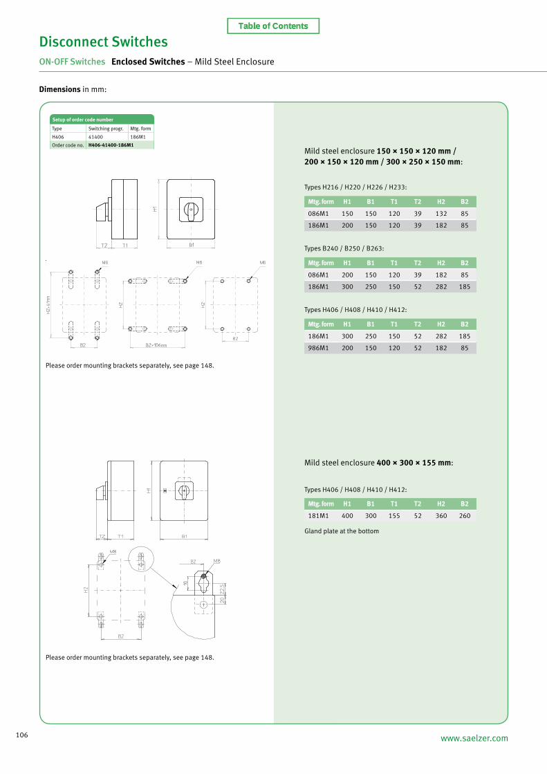
Dimensions in mm:
Mild steel enclosure 150 × 150 × 120 mm /200 × 150 × 120 mm / 300 × 250 × 150 mm:
Mtg. form H1 B1 T1 T2 H2 B2
086M1 150 150 120 39 132 85
186M1 200 150 120 39 182 85
Types H216 / H220 / H226 / H233:
Mtg. form H1 B1 T1 T2 H2 B2
086M1 200 150 120 39 182 85
186M1 300 250 150 52 282 185
Types B240 / B250 / B263:
Mtg. form H1 B1 T1 T2 H2 B2
186M1 300 250 150 52 282 185
986M1 200 150 120 52 182 85
Types H406 / H408 / H410 / H412:
Setup of order code number
Type Switching progr. Mtg. form
H406 41400 186M1
Order code no. H406-41400-186M1
Mild steel enclosure 400 × 300 × 155 mm:
Mtg. form H1 B1 T1 T2 H2 B2
181M1 400 300 155 52 360 260
Gland plate at the bottom
Please order mounting brackets separately, see page 148.
Please order mounting brackets separately, see page 148.
Types H406 / H408 / H410 / H412:
Table of Contents
107
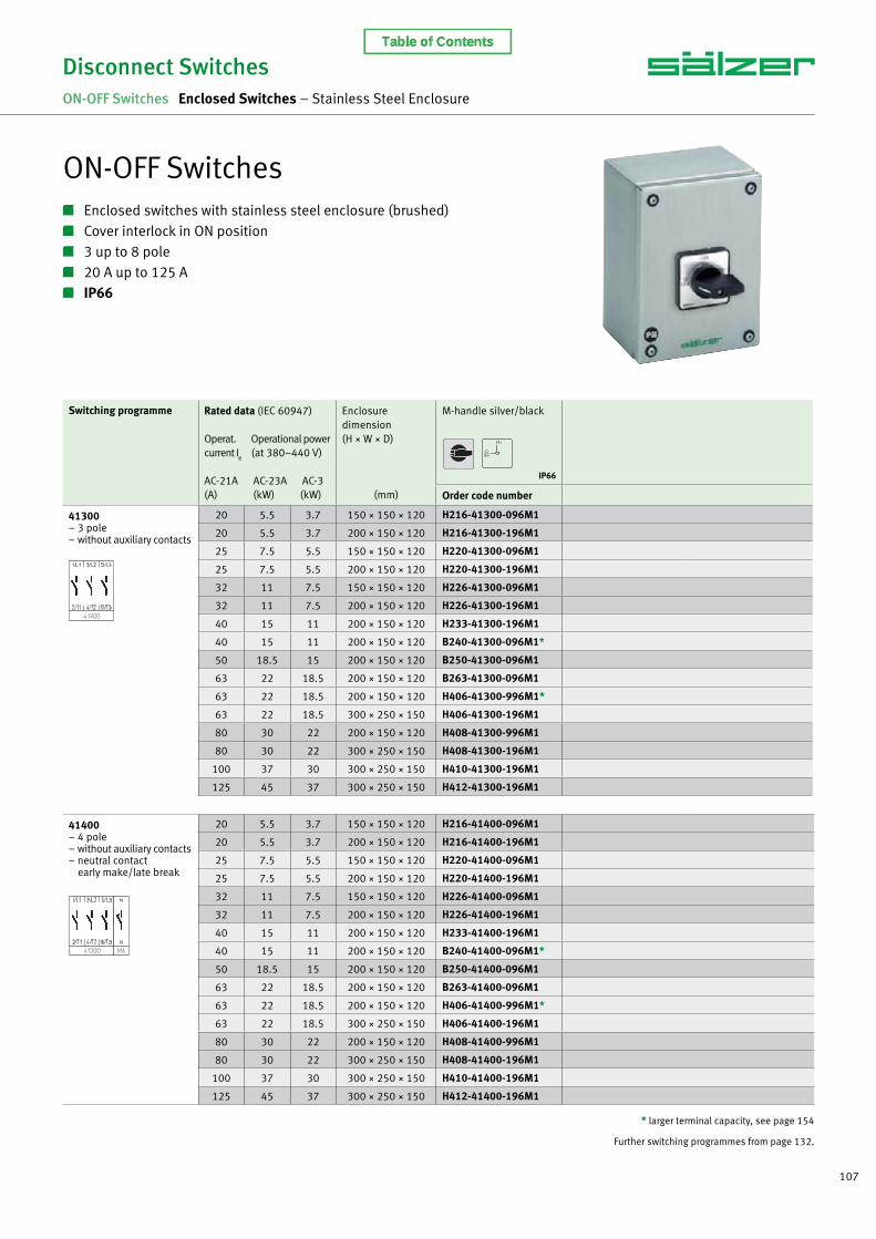
ON-OFF Switches Enclosed switches with stainless steel enclosure (brushed) Cover interlock in ON position 3 up to 8 pole 20 A up to 125 A IP66
Disconnect SwitchesON-OFF Switches Enclosed Switches – Stainless Steel Enclosure
Switching programme Rated data (IEC 60947)
Operat. Operational power current I
e (at 380–440 V)
AC-21A AC-23A AC-3(A) (kW) (kW)
Enclosuredimension(H × W × D)
(mm)
M-handle silver/black
Order code number
41300 – 3 pole – without auxiliary contacts
20 5.5 3.7 150 × 150 × 120 H216-41300-096M1
20 5.5 3.7 200 × 150 × 120 H216-41300-196M1
25 7.5 5.5 150 × 150 × 120 H220-41300-096M1
25 7.5 5.5 200 × 150 × 120 H220-41300-196M1
32 11 7.5 150 × 150 × 120 H226-41300-096M1
32 11 7.5 200 × 150 × 120 H226-41300-196M1
40 15 11 200 × 150 × 120 H233-41300-196M1
40 15 11 200 × 150 × 120 B240-41300-096M1*
50 18.5 15 200 × 150 × 120 B250-41300-096M1
63 22 18.5 200 × 150 × 120 B263-41300-096M1
63 22 18.5 200 × 150 × 120 H406-41300-996M1*
63 22 18.5 300 × 250 × 150 H406-41300-196M1
80 30 22 200 × 150 × 120 H408-41300-996M1
80 30 22 300 × 250 × 150 H408-41300-196M1
100 37 30 300 × 250 × 150 H410-41300-196M1
125 45 37 300 × 250 × 150 H412-41300-196M1
41400 – 4 pole – without auxiliary contacts – neutral contact early make/late break
20 5.5 3.7 150 × 150 × 120 H216-41400-096M1
20 5.5 3.7 200 × 150 × 120 H216-41400-196M1
25 7.5 5.5 150 × 150 × 120 H220-41400-096M1
25 7.5 5.5 200 × 150 × 120 H220-41400-196M1
32 11 7.5 150 × 150 × 120 H226-41400-096M1
32 11 7.5 200 × 150 × 120 H226-41400-196M1
40 15 11 200 × 150 × 120 H233-41400-196M1
40 15 11 200 × 150 × 120 B240-41400-096M1*
50 18.5 15 200 × 150 × 120 B250-41400-096M1
63 22 18.5 200 × 150 × 120 B263-41400-096M1
63 22 18.5 200 × 150 × 120 H406-41400-996M1*
63 22 18.5 300 × 250 × 150 H406-41400-196M1
80 30 22 200 × 150 × 120 H408-41400-996M1
80 30 22 300 × 250 × 150 H408-41400-196M1
100 37 30 300 × 250 × 150 H410-41400-196M1
125 45 37 300 × 250 × 150 H412-41400-196M1
* larger terminal capacity, see page 154
Further switching programmes from page 132.
IP66
Table of Contents

108 www.saelzer.com
Switching programme Rated data (IEC 60947)
Operat. Operational power current I
e (at 380–440 V)
AC-21A AC-23A AC-3(A) (kW) (kW)
Enclosuredimension(H × W × D)
(mm)
M-handle silver/black
Order code number
41600 – 6 pole – without auxiliary contacts
20 5.5 3.7 200 × 150 × 120 H216-41600-196M1
25 7.5 5.5 200 × 150 × 120 H220-41600-196M1
32 11 7.5 200 × 150 × 120 H226-41600-196M1
40 15 11 200 × 150 × 120 H233-41600-196M1
40 15 11 300 × 250 × 150 B240-41600-196M1
50 18.5 15 300 × 250 × 150 B250-41600-196M1
63 22 18.5 300 × 250 × 150 B263-41600-196M1
63 22 18.5 300 × 250 × 150 H406-41600-196M1*
80 30 22 300 × 250 × 150 H408-41600-196M1
100 37 30 300 × 250 × 150 H410-41600-196M1
125 45 37 300 × 250 × 150 H412-41600-196M1
41800 – 8 pole – without auxiliary contacts – 2 neutral contacts early make/late break
20 5.5 3.7 200 × 150 × 120 H216-41800-196M1
25 7.5 5.5 200 × 150 × 120 H220-41800-196M1
32 11 7.5 200 × 150 × 120 H226-41800-196M1
40 15 11 200 × 150 × 120 H233-41800-196M1
40 15 11 300 × 250 × 150 B240-41800-196M1
50 18.5 15 300 × 250 × 150 B250-41800-196M1
63 22 18.5 300 × 250 × 150 B263-41800-196M1
63 22 18.5 300 × 250 × 150 H406-41800-196M1*
80 30 22 300 × 250 × 150 H408-41800-196M1
100 37 30 300 × 250 × 150 H410-41800-196M1
125 45 37 300 × 250 × 150 H412-41800-196M1
* larger terminal capacity, see page 154
Further switching programmes from page 132.Dimensions in mm:
Mtg. form H1 B1 T1 T2 H2 B2
096M1 150 150 120 39 132 85
196M1 200 150 120 39 182 85
Types H216 / H220 / H226 / H233:
Mtg. form H1 B1 T1 T2 H2 B2
096M1 200 150 120 39 182 85
196M1 300 250 150 52 282 185
Types B240 / B250 / B263:
Mtg. form H1 B1 T1 T2 H2 B2
196M1 300 250 150 52 282 185
996M1 200 150 120 52 182 85
Types H406 / H408 / H410 / H412:
Setup of order code number
Type Switching progr. Mtg. form
B240 41800 196M1
Order code no. B240-41800-196M1
Please order mounting brackets separately, see page 148.
Disconnect SwitchesON-OFF Switches Enclosed Switches – Stainless Steel Enclosure
IP66
Table of Contents


![Applications / Markets ANTI-VANDAL SWITCHES DETECTOR ... · [.031 in] 11.00 [.433 in] 11.00 [.433 in] 27.00 [1.063 in] this terminal only on 3 - position switches 2 off none on eof](https://img.dokumen.tips/doc/110x75/5fba74ab042b113b3d3e0b88/applications-markets-anti-vandal-switches-detector-031-in-1100-433-in.jpg)