Embed Size (px)
Citation preview

THE IMPACT OF CROUP TECBNOLOGY-BASED SHIPBUILDING METHODS ON NAVAL SHIP DESIGN AND ACQUISITION PRACTICES
by
JOHN SUTHERLAND HEFFRON
B. S., Computcr Science, Louisians State University (1974) M. S., Applied Mathematics, University of Arkansas (1976)
Submitted to the Department of Ocean Engineering
In Partial Fulfillment of the Requirements For the Degrees of
NAVAL ENGINEER
MASTER OF SCIENCE
MASSACHUSETTS
and
IN OCEAN
at the
INSTITUT
May, 198
SYS'I
'E OF
8
'EMS MANAGEMENT
TECHNOLOGY
- @ John Sutherland Heffron, 1988
The author hereby grants to M.I.T. and to the United States Government permission to reproduce and to distribute copies of this thesis document in whole or in part.
. ... . -...
Signature of Author ~ e p a r t m e n t s 0dianW%ng2neer ing
pa9 6, 1988 I
Certified by Y A, %- Henry S. Marcus
Associate Professor of ~ a r i n e Systems Thesis Supervisor
Certified by Paul E. Sullivan
Associate Professor of Naval Architecture Thesis Reader 4 P I LY. / *
Accepted by i . f c ( / & a , / c ~ I
cir%+,W.c '
A ./ D o u g l d r m i c h s w l , Chairman ~e~artmental Graduate Committee Deptirtment of.Ocean Engineering

THE IMPACT OF GROUP TECHNOLOGY-BASED SHIPBUILDING METHODS ON NAVAL SHIP DESIGN AND ACQUISITION PRACTICES
JOHN SUTHERLAND HEFFRON
Submitted to the Department of Ocean Engineering on May 6, 1988 in partial fulfillment of the
/ requirements for the Degrees of Naval Engineer and /'
L Master of Science in Ocean Systems Management
\ ABSTRACT
-- . / ----BM~dern shipbuilding practices in the Un$'ted States have
evolled from the requirement to b hips 8s econom- ically as possible while still re desired level of quality and the ability to ful ments. The highly competitive en are now in has further stimulated efficient and productive ship con thods. As a result, group technology-based sh ethods have been developed and implemented ov These new c~nstruction~technologi the manner in which naval ship ac is, or should be, conducted. In particular, there a s consequences regarding engineering and design, , ship work break- down structures, and cost and schedule control systems.? ____- -,--' - - .-_.. _ _-..-/'
-\a brief history of naval ship design and acqui- sition practices, leading to a description of the current shipbuiiding technologies, is given. hen the effects there technologies have on the'above-mentioned areas of the naval ship acquisition process are described, Included are detailed examples of how modern shipbuilding methods have affected selected naval ship acqul3ition programs, Finally, changes in some of these areas will be recommended '$ o that modern ship construction and outfitting techniques cbn be more fully meshed into the total naval ship acquisition pro- cess, thereby enhancing the productivity gains these \tech- niques have already made.
Thesis Supervisor: Henry S. Marc~s, D.B.A.
Title: Associate Professor of Marine Systems '% . (E

The nuthor extends hi9 gratitude and thanks to
Professor Hank Marcus whose guidance and support made
this thesia possible.

to my wife, Elizabeth, and my daughter, Sarah

TABLE OF CONTENTS
ABSTRACT . . . . . . . . . . . . . . . . . . . . . . . 2 ACKNOWLEDGEMENTS . . . e a 3
. . . . . . . . . . . . . . . . . . . TABLEOFCONTENTS 5
CHAPTER 1 . INTRODUCTION . . e . 0 e . 10
. . . . . . . . . . . . . . . . . . 1 . 1 Background 1 0
. . . . . . . . 1 . 2 Thesis Overview and Objectives 12
. . . . . . . . . . . . . . References to Chapter 1 1 5
CHAPTER 2 . NAVAL SHIP ACQUISITION AND SHIPBUILDING. . . . . . . . . . . WORLD WAR I1 TO PRESENT 1 6
2 . 1 Post World War I1 Naval Ship Acquisition . . . 1 6
. . . . . . . . . . . . . . 2 . 1 . 1 Introduction 16 . . . . . . . . . . . 2 . 1 . 2 The Basic Process 1 7 . . . . . . . . 2 . 1 . 3 The Conventional Period 1 9 2 . 1 . 4 The Total Package Procurement Period . . 22 . . . . . . . . 2 . 1 . 5 The Post McNamara Period 2 6 . . . . . . . . . . . 2 . 1 . G The Current Period 3 7
2 . 2 A Brief History of Modern Shipbuilding Methods 4 3
2 . 3 Modern Shipbuilding in the United States Today 46
. . . . . . . . . . . . . . 2 . 3 . 1 Introduction 4 6 . . . . . . . . . . . . 2 . 3 . 2 Group Technology 46 2 . 3 . 3 Product.-Oriented Work Breakdown
Structures . . . . . . . . . . . . . . . 4 9 . . . . . . . . 2 . 3 . 4 Planning for Production 5 3 . . . . . . . . . . . 2 . 3 . 5 Process Flow Lanes 6 0 . . . . . . . 2 . 3 . 6 Zone Construction Methods 6 2 . . . . . . . . . . . . 2 . 3 . 7 kccuracy Control 7 3
. . . . . . . . . References and Notes to Chapter 2 7 6

CHAPTER 3 - MODERN SHIPBUILD?NG AND NAVAL SHIP ACQUISITION PRACTICES. . e e e e 80
3.1 Introduction . . . . . . , . . . . . . . . . . 80 . . . . . . . . . . . . 3.2 Design and Er.gineering 80
3.2.1 Qroup Technology Design m d Engineering - General Concepts. . 81
3.2.2 Group Technology Design and Engineering - Bxamplea. . . . . . . . . 87
3.2.3 Group Technoloey Design and Standardization . . . . . . . . . . . . 94
3.2.4 Design Change8 in a Group Teohnology Engineering Environment . . . . . . . . 99
3.2.5 Group Technology Design Prodmts. . . . 107
Appendix C - Product Work Breakdown Structure . . 147
3.4 Work Breakdown Structures (WBS) and Cost . . . . . and Schedule Control Systems (C/SCS) 118
3.5 Learning Curve affects in Group Technology . . . . . . . . . . . . . . . . . Shipbuilding 126
References to Chapter 3 . . . . . . . . . . . . . . 129 CHAPTER 4 - CONCLUSIONS AND RECOMM3NDATIONSe e 131
4.1 Conclusions. . . . . . . . . . . . . . . . . . 131 4.2 Recommendations. . . . . . . . . . . . . . . . 133
APPENDICES . . . . . . . . . . . . . . . . . . . . . . 141
Appendix B - Extended Ship Work Breakdown Structure. . . . . . . . . . . . . . 145

LIST OF TABLES
2.1 The Navy Expanded Ship Work Breakdown Structure (BSWBS) Major Group.
3.1 Engineering Effort for the TAO 187
3.2 TAO 187 Machinery Space Design and Conatruction Results
3.3 Engineering Impaot of Selected Changes in the CG 47 and DDQ 5 1 Shipbuilding Psograma
3.4 Engineering-related Man-hours for DDC 61 Spiral-wound Qasket Filler Material Change
3.5 Description of Contract. WBS Eleaents for the LSD 44 Shipbuilding Program
3.6 Recurring Ship Production Costa for the TAO 187 Program

LIST OF FIGURES
2.1 Comparimon of the Development Sequence of the Navy's Earlier Ship Aoquimition Method.
2.2 OPNAV/NAVSEA Ship Desian Dialogue
2.3 Summary of Naval Ship Design Approaches
2.4 An Example of the IiSWBS Organieation
2.5 Elements of the Three-dimensional PWBS Matrix
2.6 Iterative Development of Work Packages
2.7 System and Zone Orientation in the Shipbuilding Process
2.8 PWBS Ship Design Process
2.9 Process Flow Lanes in Modern Shipbuilding
2.10 PWBS Components
2.11 FBCM Manufacturing Levels
2.12 HBCM Classification by Product Aspects
2.13 ZOFM Manufacturing Levels
2.14 ZOFM Classification by Product Aspects
2.15 ZPTM Manufacturing Levels
2.16 ZPTM Classification by Product Aspects
Conventional vs, Croup Technology Design and Engineermg
Avondale Industries' Design and Construction Methods, Convent.iona1 vs. Current
Classification of Standards
Standard Structural Assembly Detail
Standard Machinery Arrangement Module
Standard Piping Layout Module

3.7 Standard Outfit Unit Module 97
3 , 8 The Rehtionrhip of m Shipbuilding Data Base to the Ship Deaign Prooean I1 1
3.9 Advanced Integrated CAD/CAM Network 113
3,10 Notional CALS Syatem 116
3,11 rrincipal Data Tranmfer Interface. in a CALS Syatem 117
3.12 LSD 44 Program Contract WBS Physioal Element8 122
3.19 A Portion of the LSD 44 Program Responsibility Assignment i-iatrix 125

CHAPTER 1
INTRODUCTION
1.1 Backnround
In April. of 1986 the Preaident'a Corriaaion on Defenme
Management publimhed a report on defenat aoquirition I l l .
The commiosion had been formed, in part, to help deal with
Department of Defense problema related to overpriced .pare
parts, test deficiencies, and coat and achedule overrun8.
Their analysis led to the concluuion that the defense acqui-
sition process has fundamental problems that muat be cor-
rected. These problems are deeply entrenched and have
developed over several decades as a result of an expanding
bureaucracy with its tendenoy for overreuulation. A s a
result, too many weapon systems cost too much, take too long
to develop, and, by the time they are fielded, feature obso-
lete technology. The typical acquisition cycle time, from
the time a mission or system requirement ia defined until
the system is operational, has grown to twelve or fifteen
years or more for complex systems.
In the opinion of the President's commission it should
be possible to cut this cycle time in half by implementinu
the following recommendations:
* streamline acquisition organization and procedures,
* expand the use of comnercial products, t increase the L-e of competition,

8 enhance the quality of aoquimition permonnel,
8 balanoe comt and performance,
* rtabilite program., and
t ure technoloay to reduce oo8tm and aohedulem,
It iu the lart recommendation that in central to thir
theoir. In the broadert context thim theaim im about the
effect. modern oonatruotion teohnoloaiem have on dafenme
acquimition practices. In particular it is about the
effect. they havb on naval mhip aoquimition practice8 and
shipbuilding productivity.
Many diacuaaiona of naval ahip acquimition begin with
t h ~ acknowledpmont that major defenoe weapona systems are
the most technically complex of any in existence. And it
can be argued that the most oomplcx of weapon. myatemu are
naval ships.
Ships are the largest mobile object8 on Earth and naval
ships represent an integration af a multitude of major and
minor related systems of which many are extremely complex in
their own right. A nuclear-powered aircraft carrier is over
1100 feet long, displaces over 90,000 tons of sea water, and
is propelled at speeds in excess of 30 knota by power plants
rated at over 200,000 shaft homepower. It is also an air-
port with a capacity of 100 or more jet aircraft. Addition-
ally, it is a self-contained city with a population of over
5,000 people. Its multi-reactor nuclear plant, various
electronic systems and aircraft launching and recovery sys-

temr take years to deaian and teat before they are ready for
inatallation and ume in the fleet,
Unfortunately, the oomplexity of the hardware in qusa-
tion ir perhapa only matched by the oarplexity of the
bureaucracy and prooess cm2erned with the aoquiaition of
the hardware, During World War 11, the entire Navy Depart-
ment in Waahington, D, C., charled with direoting an effort
involving, at the peak of the war, thouaandm of uhipr, oon-
sisted of about 200 people, Today there are in exceaa of
20,000 people in the Waahington, D. C, area employed by the
Navy. The active fleet today 3onsiats of cloae to 600
ships.
A 8 indicated earlier, it commonly takes twelve to fif-
teen years to oonoeive, develop, derign, and oonstruct a new
9. S . Navy ship class. The problems of long range fiscal
forecasting and engineering development in an unstable
political and economic environment, coupled with rapid
technological advances, are mind boggling, Any technology
G r methodology that offers to reduce the cycle time and the
costs of the acquisition process deserves close study and
development,
1.2 Thesis Overview and Objectives
Modern shipbuilding practices in the United Stetes have
evolved from the requirement to build naval ships as econom-
ically as possible while still retaining the desired level
of quality and the ability to fulfill naval misaion require-
ments. The highly competitive environment that shipbuilders
are now in has further stimulated their search for more
efficient and productive ship construction methods. As a
result, group technology-based shipbuilding methods have
boen developed and implemented over the last few years.
These new construction technologies have profound effects on
the manner in which naval ship acquisiti~n is, or should be,
conducted. In particular, there are serious consequences
regarding engineering and design, CAD/CAM, ship work brcak-
down structures, and cast a,nd schedule control systems.
The second chapter of the thesis begins with a discus-
sion of the four distinct strategies employed in defense
systems acquisition since World War 11, The reader should
gain from this material background knowledge about the naval
ship acquisition process and environm~at. Included is a
description of the naval ship design process as viewed by
the Naval Sea Systems Command (NAVSEA), the organization
within the U, S, Navy responsible for acquiring ship sys-
tems. Next is a brief history of the developaent of modern
shipbuilding methods in the United States, their subsequent
transfer to and improvement in Japan, and finally their
return to the United Stat.es. The chapter ends with a tech-
nical overview of ship producibility and modern shipbuilding
methods. Included here is a dipcussion of group technology;
product-oriented work breakdown structures; planning for

production; process flow lanes; zone construction, outfit-
ting, and painting methods; and accuracy control. Sinoe
this material has been recently collected in a comprehensive
treatment of modern ship production methodology and 3rao-
tices, the discussion is brief [2] . With the above information established, Chapter 3 then
considers the impacts modern shipbuilding methods have on
the naval ship acquisition process. The particular areas
considered are design and engineering, CAD/CAM, ship work
breakdown structu~es, and cost and scheduls control systems.
Included are detailed examples of how modern shipbuilding
methods have affected selected acquisition programs. The
programs considered include the TAO 187 class fleet oiler
shipbuilding program, the DDS 51 class destroyer shipbuild-
ing program, and the SSBN 726 class Trident ballistic mis-
sile submarine shipbuilding program.
Based on the discussions of Chapter 3, the final chap-
ter offers conclusions and recommendations on how the naval
ship acquisition process may be changed so that the improve-
ments thus far made in ship construction methods may further
reduce ship acquisition construction times and costs.

REFERENCES TO CHAPTER 1
1. "A Formula for Action, A Report to the Prsoident?on Defense Acquisition by the President's Blue Ribbon Commia- sion on Defense Management", April, 1986.
2 . Storch, R. L., Hammon, C. P., and Bunch, H. M., Ship Production, Cornell Maritime Press, Centreville, Mary- :and, 1988.

CHAPTER 2
NAVAL SHIP ACQUISITION AND SHIPBUILDING,
WORLD WAR I1 TO PRESENT
2,l P ~ s t World War I1 Naval Shiw Acauisition
2.1.1 Introduction
An overview of the etructure and proueas of naval ship
acquisition in the United States since World War I1 is.
presented in this ~ection, Four distinct periods are iden-
tifiable: the conventional period (until the ear* 1960's),
the total package procurement period (also called the con-
cept formulation/contract definition or the McNamara period,
after the then Secretary of Defense Robert S. McNamara)
which began in the early 1960's acd ended about 1969, the
post NcNamara period which ended about 1979, and the current
period. Although the major policies and characteristics of
the four periods differ considerably, it is not always pos-
sible to oate~orize a particular ship acquisition project as
being a result of the policies of any one period. For
example, the nuclesr-powered aircraft carrier project
(Nimitz Class) was conceived during the conventional period,
continued through the total package procurement and post
McNamara periods, and remains an ongoing project. It has
characteristics of all four policy periods. The ships were
designed primarily by the Navy ("in house") with the aid of
a design agent, typical of the conventional, post McNamara,

and current periods. Some of the ahips were constructed
under a multi-ship, multi-year oontmmct, which ie chnracter-
istic of the total packsue proourement and poet McNamara
periods,
Thus, as the different periods are described, it should
be remembered that ship projects are lone (twelve to fifteen
years or more) and often transcend major aaquisition policy
shifts. Additionally, like any large bureaucracy, new poli-
cies and strategies from top management (the Secretary of
Defense) often do not take effect at the working level (the
ship projects) for two or three years, if at all,
2.1.2 The Basic Process
Although policies and organizational structures for
designing and acquiring ships for the United States Navy
have changed over the years, the basjc process remains much
the same. Also, though differing in details and nomencla-
ture, the acquisition of ships, at the most basic level, is
similar to the acquisition of other major defense ~ystems.
A need is identified; a requirement bssed on that need is
established; a weapon system is selected, designed, devel-
oped and constructed to fill the requirement. Sometimes
technological breakthroughs motivate a new acquisition but
attempts Are made to ensure that a legitimate need, and not
"technology push", precedes the development and construction
of a new system.

The Navy and other aervices are charged with identify-
ing needs and defining, developing, and producing system to
satisfy those needs [l]. Eatablishing averall acquisition
policy, passing on the validity of needs, and monitoring the
performance of the services in carrying out the policy is
the responsibility of the Office of the Secretfry of Defense
[21
National defense policiee and objectives m e provided
by the Secretary of Defense and translated by the Joint
Chiefs of Staff into military policies and objectives.
Planning and programming by the services are keyed to +,hese
objectives, Evaluation of the Joint Chiefs of Staff guid-
ance may lead to research and development objectives formu-
lation by the services to satiefy deficiencies in their
capabilities to perform their respective missions [ 3 ] . The
Program Objectives Memorandun (POM) is the budget for this
effort and for the weapons systems which emerge from the
research and development efforts [ 4 1 .
The POM is part of the Department of Defense Planning,
Programming, and Budgetink System (PPBS). Funding for weap-
ons systems is obtained through the PPBS. However, a series
of approvals by intra-service organizations and the top
level Defense Systems Acquisition Review Council (DSARC) is
also currently required before a new weapons system is
built. The role of the DSARC will be discussed in more
detail iater in this section,

2.1.3 The Conventional Period
At the end of World War 11 the U. S. Navy deactivated
most of its fleet and ahip production virtually ceased, Dur-
ing the Korean conflict moat of the required ships were
reactivated World War II-era ships. Finally, in 1952, the
Navy directed the construction of 31 major ships [ 5 1 *
Acquisition practices were characterieed by an itera-
tive design process accomplished by the Navy or by an inde-
pendent design agent working for the Navy. Their products
included a complete construction tid package with little
documentation. The major emphasis was on ship performance
and production contracts were often split between two or
more shipbuilders. There was little involvement by the
Office of the Secretary of Defense. The acquisition process
was basically decentralized to the service level.
Initially, the entire design and procurement effort
would be coordinated by a few people. They relied on vari-
ous functional organizations to perform the necessary design
and acquisition work required. Different organizations
would be responsible for various systems on the ship. For
example, the Bureau of Ordnance has responsible for weapons.
Later, starting with the Polaris ballistic missile program,
the trend was toward project manager-type organizations.
Production contracts were spread among several ship-
yards to facilitate more rapid delivery of ships and to aid
in preserving the shipbuilding and ship mcbilization indus-

trial base. Of course, regional political and economic
pressuren also played a role.
As ahown in Figure 2.1, the conventional approach
involved Navy personnel formulating sr ship ccmoept. This
activity included coot and feasibility studies and possibly
advanced research and development. Assuming budgetary
approval was ob+.ained, increasingly refined design ntages,
termed preliminary design and contr~ct design followed. This
approach did not employ systems analysis techniques.
The resulting product was a bid paokage, i;.bluding
complete contract plans and specifications. The bid package
could result in any number of procurement oontracts. Lead
ships were often built in Navy shipyards. The amphibious
ships LPD 7 through 15 were built under four oo~tracts by
two shipbuilders. Exclusive of the costs of changes to the
contracts, these ships were delivered to the Navy at an
average of 25% over the initial co~~tract price and 27 months
behind schedule 1 7 1 , Escalation due to inflation and claims
against the government accounted for most of the cost over-
runs. These results became increasingly typical. Low or
negative profit performance precipitated many of the claims.
The basis for the claims was usually a dispute over inter-
pretation of the complex and detailed contract specifica-
tions. Also, production facilities were becoming antiquated
and uncompetetive in the world market. Support of the ships
was costly and often inadequate due to lack of standardiza-

Conventional Period
Conceptual Preliminary Contract Detail Production Studies - Design - Design -"Deeign*
~ ~ a v y * ~ - ~ a v y or Deaign *gent+- Shipbuilder 4
Total Package Procurement P e r i d
Contract Definition
Concept Ship- Ship- Ship- Detail P.?oduction Formulation-builder builder builder-Design-
A B C
Shipbuilder kNaVY + Competition Single
4 S h i p b ~ i l d e r 4
Post Mcliamara Period
Feasibility Concept Preliminary Lead Ship Studies 'Design - Design - ~ontraot Design -
k- Navy --Navy with Shipbuilder ( a ) -7-4
-m Lead Ship Detail Design-Follow Ship Contraot Design,
and Production Detail Design and Production
11 shipbuilder (s .4
Figure 2.1 Comparison of the Development Sequence of the Navy's Earlier Ship Acquisition Methods 161

tion among ship. of a given c l a m and among clessea of
hip^,
2.1.4 The Total Packwe Prouurement Period
A radically different agproaoh to weapon. deaign and
acquisition was formulated in the early 1960'. by the Office
of the Secretary of Defenme under Robert S. MoNamara. The
new approach centralized major decision authority in McNa-
mara's office. Objective8 were:
a) optimization of cost effectivenesa by using systems
analysis techniques;
b) reduction or elimination of contractor claims
against the govqrnment by using contrautor-prepared perfor-
mance oviented speoifioations instead of government-imposed
detailed specifications;
C) reduction of cost overruns b~ transferring financial
risk to the contractors for the design and acquisition
phases through the use of fixed price contracts;
d ) significant ca2italization increases in ehipbuilding
facilities by using multi-ship, mdti-pear contract awards
to a single shipbuilder (This was expected to provide long
term financial security, thus enabling large-scale capital-
ization and expansion of facilities to accommodate delivery
schedule demands);
e! reduction of unique systems and subsystems prolif-
eration which had resulted from split production contracts;

f) introduction of produoibility and innovation into
designs by having the shipbuilder design the aymtem;
g) lower acquisition aoats by taking advantage of the
learning curve offeot made poamible through sinale-producer
serial production; and
h ) more acourate total oort ertiratea and reduotion of
poor rhip support by making the contraotor responsible for
all on-board systems, orew training, initial repair parts,
support facilities, and other lotrirtioe detail. 181.
A project manager-type organieation wan direoted for
all major programs [ 9 ] . As outlined in Figure 2.1, the
services still conducted rerearch and development and iden-
tified the desired performance characteristics of the weapon
system during the aoncept formulation stage. Assuming
approval by the Secretary of Defense, a contract definition
period followed. A request for proposal (RFP) was prepared
by the Navy and issued to selected shipbuilders to prepare
design analyses based on the specified performance charac-
teristics. The RFP contained both mandatory and desirable
performance specifications and were supposed to encourage
alternatives and stimulate initiative and creativity on the
part of the contractors [lo].
After evaluation of the proposals by the Navy, normally
two or more contractors were awarded fixed price contracts
to develop a complete shipbuilding proposal. Required in
these proposals were contract plans and specificatiors,

detailed oonstruotion planm, management planm, and a com-
plete analyaia of life cycle comts [ill. Life opcle cortc
are the total costa of aoquisition and ownermhip, includina
development, production, deployment, operation, and rainte-
nance I
No longer than mix month* war allowed for the contraot
definition phase. This was followed by a souroa relaction
proceaa during which a detailed analpais of the proposal8
was conducted by the procuring servioe. Nepotiation was
conducted with one or more of the potential contractors. At
the conclusion of the evaluation period a recommendation was
sent to the Office of the Secretary of Defense to award a
multi-year, multi-ship contract to the releated contractor,
to conduct further contraot definition, or to defer or
abandon the effort. The aingle contract award wa8 fixed
price, with or without incentive clauoes.
The Navy conducted three total paokage procurement ahip
competitions. The Fast Deployment Logistics ship war not
funded by Congress. The Amphibious Helicopter Assault ships
(LHA class) and the SkRUANCE class destroyers were funded
and their acquisition programs completed. Litton Industries
won all three competitions [ 1 2 ] .
The USS Spruance was the first ship delivered under
either contract and was accepted by the Navy in 1975. Yow-
eve:, the acquisitions were beset by many of the same prob-
lems that characterized defense weapons procurement during

the previour period - large coat end schedule overruns. Thin war particularly true of the LHA oontract, The firat
LHA waa delivered years behind rohedule, even after the
original uontract waa renegotiated, allowing for a higher
contract price and later delivery date.
By the late 196OVa, coat and achedule overruna and
performance shortfalls of new weapon. ryatems were daily
newa~aper fare. In 1971 the Department of Defense Coa-
ptroller conducted a survey of 35 major development and
production programa [13]. Only two of the program were
found to be on, or ahead of, schedule. That aame year the
Geneieal Acoounting Office made a survey of 61 weapon system8
and found that coat estimates for them had increased $33.4
billion over the initial estimates [14]. Contractor coats
soared and profit8 plummeted. The term "oontraotor bailout"
became a household word as one producer after another
threatened to ceaae production unless relief from the fixed
price contracts waa provided.
By 1970 a number of atudies had found aerious flaws in
the management of the weapons acquisition process. As a
result, on May 28, 1970, Deputy Secretary of Defense David
Packard issued a memorandum which stated that the total
package procurement approach to developing and acquiring
major weapon systems was unsatisfactory and that a new pol-
icy would soon be established [ 1 5 ] . The Navy was till
years away from delivery of its first ship procured under

the aanceled polioy. The overall oonaluaion wan that the
long term obJectiver of total paokage proourerent were aever
met. It ir a faat that the mole sou-ce multi-year oontmctm
rerultad in the conrtruction of a new rhipyrrd by Litton
Induatriea in Paroagoula, Minoiasippi. However, Litton had
problamr in developiug an adequate derign and production
force and in making the new faoility operationally effioient
during the performanoe period of their contraotr.
2.1.5 The Post MoNamw Period
The major policies and trend@ of rhip acquisition fol-
lowina the demire of total package procurement inoluded:
a) emphasis on constrained deoign ("design-to-co~t"),
b) emphasis on proven hardware ("fly-before-you-buy"),
C ) required review and approval to prooeed by the DSARC
at key milestones,
d ) a prohibition against total package proourement8
e) improvement in coat estimating,
f) flexibility in contract type and liberalization of
contract escalation (due to inflatioc) clauses,
g ) use of contractors for "in-house" rhip design, and
h) tailoring of acquisition approaches to each project.
The cancellation of the key top level policy directive
[ 1 6 ] for the total package procurement period in 1970 left a
guidance void that was not formally filled until the issu-

ance of Department of Defense Directive 5800.1, "Acquisition
of iqajor Defense Systems", on July 13, 1971. It was during
this same period that then Chief of Naval Operations Elmo
Zumwalt directed the rapid development of a large class of
austere, rslatively inexpensive Guided Missile Frigates (FFC
class) to bolster the size of the rapidly diminishing fleet
[17]. They provided the "low" end of the so called "high
mix/low mix" fleet concept.
After a year of feasibility studies, Admiral Zumwalt
directed that the design would not violate constraints which
were set on the average follow ship acquisition cost, fully
loaded displacement, and maximum number cf accommodations
[18]. Performance capability above the minimum specified
was to be traded-off to stay within the constraints. This
method of ship design, commonly termed "design-to-cost", was
revolutionary to the Navy, but was common . n industry for
new product development.
A major program consideration was that "discrete cost
elements (e.g., unit production cost, operating and support
cost) shall be translated into 'design toJ requirements"
[191. In October, 1973 the major servicesJ material com-
mands issued the "Joint Design-to-Cost Guide" [20]. This
directive required that "design-to-cost" methodology be used
for most major systems.
Historically, performance requirements for new ships
had been dictated by the Chief of Naval Operations to the

material command in brief "single sheet charact,eristicsW
(211. These were used by the material command to develop
preliminary designs and cost estimates leading to more
detailed characteristics statements, and ultimately to pro-
curement specifications [22]. Costs were considered but
were usually secondary to maximizing performance.
"Design-to-cost" elevated the importance of acquisition
cost to the same level as performance in the design process.
As a result, a new performance-cost tradeoff dialogue
between the customer (Chief of Naval Operations) and pro-
ducer (Chief of Naval Material) organizations was required.
"Top Level Requirements and Top Level Specifications for the
Development of Naval Ships", Chief of Naval Operations
Instruction 9010.300, was issued early in 1974. It detailed
a procedure which provided for a working level group (the
Ship Acquisition and Improvement Council) to develop the
performance parameters for a baseline ship which would meet
the established mission requirements, The group also speci-
fied allowable variations in performance parameters and
alternative system selections for the ship class [23].
After a period of feasibility studies during which the
impact of the alternative performance parameters and systems
selections were evaluated, the Chief of Naval Operations
prepared a draft of the Top Level Requirements (TLR). This
document was revised as the Naval Material Command (parent
conmand of NAVSEA, for whom acquisition projacts worked

directly) developed a conceptual design for the ahip claas
and provided cost and design information to the Chief of
Naval Operations. Assuming agproval from the Chief of Naval
Operations to proceed with a selected design, a "conceptual
baseline" and a "cost goal" for the average follow ship
acquisition were presented to the DSARC, which is composed
of high level officials in the Office of the Secretary of
Defense. If DSARC and Secretary of Defense approval were
given to proceed into preliminary design, a draft Top Level
Specification was initiated by the Naval Material Command.
This companion document to the TLR translates the TLR into a
physical ship description [ 2 4 ] .
The large performance shortfalls, schedule delays, and
cost increasss referred to earlier in this chapter were at
least partially a result of overly optimistic estimates of
ultimate system capabilities and the time required to design
and perfect them [ 2 5 1 . There had been a great deal of
reliance on "paper studies" rather than on actual perfor-
mance demonstrations, Thtis, a major program consideration
of the post McNamara period was to ensure that achievement
of program objectives was assured prior to full-scale prod-
uction [ 2 6 ] . The goal was to eliminate techniaal and cost
risks. A supporting Department of Defense directive was
issued in January of 1973 to establish test and evaluation
policy for the acquisition of defense systems [ 2 7 1 .

. .
& ..- .. * . 1 :.
. , ' - , ..,- - .. ..;: :. .A . .,: t : .. . - . " _ . . . .
I I... .'
I ? * ' b . . . : - s . . ! ' . - .
I t ' . . , . 8 .
, . . .
. . . . , . . i'. . .. , ,
p i ' . r : ! . . t . I I *
I . :;., .!
The key practice which grew from recognition of the
need for increased test and evaluation during the acquisi-
tion process wai3 prototyping. This is sometimes known as
the "fly-before-you-buy" policy and was used in the Navy's
air-cushioned landing craft (LCAC) program. However, it is
not feasible to build and evaluate prototypes prior to
beginning follow ship design and production for large ships.
The time required, small number of ships usually involved,
and threat of obeolescence dictated a modified approach.
In such a modified approach, the FFG program developed
a plan which provided for:
a) early construction of land based test fmilities
(LBTFs) for complete propulsion and combat systems testing,
and
b) a delay of two years between construction contract
awards for the lead and follow ships [ 2 8 ] .
This plan permitted testing of the two major high risk
subsystems prior to installation on the lead ship and time
to incorporate changes resulting from the test and evalua-
tion program into the design of the fol.10~ ships. The LBTFs
were also useful for crew training,
The DSARC was mentioned earlier and will be explained
more fully now. It was established in the Office of the
Secretary of Defense by then Deputy Secretary of Defense
David Packard in May, 1969 1291. The purpose of the council

was to review and evaluate the status of major defense sys-
tems acquisitions at critical milestones.
Formal documentation for the DSARC reviews and deci-
sions was provided by the project-prepared Decision Coordi-
rating Paper (DCP), formerly called the Development Concept
Faper. It was a summary document that recorded the primary
information on a program. Included were thresholds, risks, a
statement of need, alternatives, rationales for decisions,
and affordability considerations. When signed . . y the Secre-
tary of Defense, it provided the authority for the service
to proceed to the next step in the program. His decision
set the limits of authority within which the project was
obligated to stay [30].
A l ~ n g series of intra-service briefings and reviews
was genrrally required of an acquisition project yrior to a
DSARC presentation.
As more and more contractors failed to perform under
the total package procurement fixed price contracts, the
need for increased government involvement with its contrac-
tors was realized. The fixed price contracts and the lack
of government involvement in the design supposedly trans-
ferred any financial risks from the government to the con-
tractor and thus the role of the acquisition projects was
basically that of monitoring, with little control leverage.
During the post McNamara period the top level acquisi-

tion policy directive specified that the contract type
should be consistent with all program aharacteristios,
including risk, Also stipulated was that cost-type con-
tracts were preferable where substantial development effort
was involved [31]. The use o; cost-type contracts allowed
the possibiiity of increased government involvement.
Apart from the lack of governmental control leverage
resulting from fixed price contracts, attempts at effective
contractor cost and schedule control by the projects had
historically been hampered by:
a) a reluctance of the contractors to share what it
considered to be proprietary information,
b) the preoccupation of project managers with the
annual. funding approval process and the continuity of funds
control as opposed to cost control,
2 ) the proliferation of various information and cost
control systems imposed on contractors by the different
services and projects (validity of the information was often
lost in the translation from the contractor's system to the
government imposed system(s) ) ,
d) the exclusion in the reporting systems of the bud-
geted cost of work performed,
e) improper allocation of contractor costs between
overhead (indirect) and direct costs,
f) inability of the project personnel to evajuate the
detailed information they require of the contractor, and

lack of correspondence between reported data and the con-
tractor's own data,
g) retroactive changing of fii~ancial plans to conform
to work performed to date (the 80-called "rubber baseline"),
and
h ) contractor use of nonintegrated work breakdown
structures and nonintegrated charts of coat accounts (sum of
budget dollars for wark at one level may exceed budget at
next higher level). [32]
In a survey conducted durlng the 1960's, it was found
that most program managers were satisfied if their funds
control reports indicated that funds were being expended at
the planned monthly rate and their PERT network reports [ 3 3 ]
showed no significant schedule slippage [ 3 4 ] . Schedule
network reporting based on starts rather than completions,
untimely or inaccurate reporting, and the lack of perfor-
mance of scheduled noncritical path work all served to build
in cost overruns which often went undiscovered until it was
too late to take any meaningful cost or schedule cortrol
action.
In 1967 the Department of Defense issued a directive
entitled "Performance Measurement for Selected Acquisi-
tions" [ 3 5 ] . The system may be summarized as follo?:~:
a) Part One of the program requires that contractors
use internal planning and control systems that meet minimum
government criteria. These criteria are called the "Cost

and Schedule Control Sy~temo Criteria" (CSCSC).
b) Part Two of the program requires that contractors
regularly submit Cost Performance Reports (CPRs) which oon-
tain information on the budgeted cost of work performed to
date. The criteria themselves do not require the submission
of any reports to the government, but specify the reporting
capabilities whieh contractorst internal systems muet have,
and the types of data the systems should be able to produce.
The contractor is free to design this internal planning and
control systems to correepond to the manner in which he
organizes his work units and assigns responsibility for
performing work [36].
The goal of CSCSC is to provide a reliable means of
measuring schedule variance, SV, and cost variance, CV,
periodically over the course of a psrticular contract. This
is done by calculating the following values, referenced to
the same time period:
ACWP = actual cost of work performed
BCWP = budgeted cost of work performed
BCWS = budgeted cost of work scheduled
CV and SV may then be calculated as follows:
CV = ACWP - BCWP SV = BCWS - BCWP
During the performance period of a contract, a positive
CV indicates a cost overrun and a positive SV indicates a
schedule slippage. Either situation is a cause for project

office ooncern.
An important conoept in the reporting criteria is that
the contract cost statue reporta must be baeed strictly on
the number of jobs completed to date.
Five years after the CSCSC had been developed, only 16
defense contr.xctore had be5n certified as complying with the
criteria, The Navy was singled out by the Senate Armed
Services Committee as being particularly slow in implement-
ing the new system [ 3 7 ] . Yn 197i an additional twenty con-
tractors complied with the criteria and all three services
were actively implementing the program and training person-
nel in its use [381 .
As indicated, the FFG program pioneered many of the
reforma of the post McNamara period. In addition to those
aspects already discussed, a key element of the period was
to select a lead and a secondary contractor early in the
design effort. The function of the lead shipbuilder was to
assist i 3 the in-house desiun effort and ultimately to build
the lead ship under a cost plus fee type of contract. The
purpose of this was to introduce producibility into the
design, to promote design familiarity and acceptance of per-
formance characteristics by the contractor, and to reduce
the development time [ 3 9 1 .
The secondary shipbuilder was involved t o prevent the
introduction of producibility bias by the lead shipbuilder,

which would result in unfair advantage when bidding on the
follow ship contraots, and to provide a fallbaok position in
came lead ahip eontract negotiations failed. When the firot
increment of follow ehip fixed price contract bids were
received in 1976, the Navy was dismayed to receive bids from
only two contractors - the lead and secondary contractors. Moreover, the bid prices were well in excess of the
"design-to-cost" constraint. The lack of participation in
the bidding by other shipbuilders and the high bids sub-
mitted were due to one or more of the following:
a) shipyard loading by other (mainly merchant ship)
contracts,
b) poor profit and loss experience on previous con-
tracts,
c) a reluctance to accept the required involvement by
the government in the contractor's procedures and oper-
ations,
d) fear that the escalation provided for inflation
would be insufficient, as it had been in the past, and
e) the Navy's cost estimate was far too low.
These difficulties in the FFG program arc generally
considered to have been the result of past project problems
and not an indication of failure of the post McNamara period
reforms. It is interesting to note that the FFG 61, the
last of the FFG 7 class, is due for delivery late in 1988.

2.1.6 The Current Period
If the total packape procurement and poet MoNamara
periods can be deecribed as periods of radioal changes in
ship aoquisition policy, then the current period is one of
evolutionary change, It can therefore be described most
conveniently in terms of the ways in which it differs from
the previous period.
During the 1980 's the watchwords of defense procurement
have been "competition" and "acquisition etreamlininu". The
Navy has responded to DoD initiatives in these areas by
creating within the Navy Secretariat. the positions of Navy
Competition Advocate General (CAG) and Navy Specification
Control Advocate (SPECAG). Both of these positions are
under the Navy Acquisition Bxecutive, who is the Assistant
Secretary of the Navy for Shipbuilding and Logistics
(ASN(S&L)) [ 4 0 ] .
The Competition in Contracting Act of 1984 requires
that full and open competition be used wherever possible in
procurement of services and material. Each ship acquisition
project manager (SHAPM) must therefore ensure that competi-
tion is provided for in his acquisition plan (AP). Any
deviation from full and open competition must be justified
by the SHAPM and approved by ASN(S&L), There are seven
exceptions to full and open competition and they include:
* existence of only one responsible source

t unusual or compelling urgency
t industrial mobilization
t international agresment
t authorieation or requirement by rtatute
t national aecurity conaiderations
t snd public interest considerations. [ 4 1 ]
Since ship acquisitions rarely fall into any of thsae oate-
gories, and since domestic commeroial ship production is
almost nonexistent, competition among the Navy's shipbuild-
ers has become intense over the last decade. This corpeti-
tion partially accounts for the recent developwent and use
of more efficient shipbuilding methods by U. S . shipbuild-
ers.
However, there is concev.n in the U. S. defense industry
that the emphasis on competition is being oarried too far.
There is evidence in recent procurements that, in the face
of increasing competitive pressures, some contractors have
been "low balling" or "buying-in" to contracts with the hope
that anticipated contract changes will offer the opportunity
to recoup what would otherwise have been an almost certain
loss. There is concern within both industry and the govern-
ment that such practices may be the prelude to a return to
the bitter claims era of the 1960s and early 1970s [ 4 2 ] .
Acquisition streamlining is any action taken to reduce
cost and time of acquisition while maintaining or improving

product quality. The objective of streamlining im to iden-
tify, develop and implement improvement. in the acquisition
procemr. Thim include. cnaurinn that only innovative and
cost-effective acquimition requirement. are included in
nhipbuildind rolioitationa and aontraot npecifications.
Management requirement8 specified in the contract ahould be
the minimum required to satirfy program need8 while allowing
the contractor the flexibility he may need to incorporate
improvements into hie shipbuilding aystem. The ooncept of
acquisition rtreamlining oalln upon induatry to be involved
early in the acquisition process by reoommending cost-
effective solutions to shipbuilding problems.
SHAPMs are required to fulfill the objectives of
acquisition streamlining in their specification and contract
development. After contract design they must certify to the
SPECAG that all streamlining requirement8 have been met
[ 4 3 1
The basic atepa of naval ship design prior to the
issuing of an RFP are largely unchanged from those of the
post McNamara period, as can be seen in Figure 2.2. [ 4 4 ]
This figure illustrates the dialogue that takes place
between the Chief of Naval Operations (OPNAV) and the Naval
Sea Systems Command (NAVSEA). An important element of the
organization in OPNAV that has yet to be mentioned is the
Ship Characteristics Improvement Board (SCIB). It includes

' T O R . OR : A TLR
CDR [ 8CECS.~
DWOS.,
PRELIMINARY CONTRACT 8tUDIE8 DE8lON Dt8lON
TOR - TENTATIVE OPERATIONAL REQUIREMENTS DOP - DEVELOPMENT OPTIONS PAPER OR - OPERATIONAL REOUIREMENT S PDR - PRELIMINARY DESIGN REPORT TLR - TOP LEVEL REQUIREMENTS CDR - CONTRACT DESIGN REPORT RFP - REQUEST FOR PROPOSAL
Figure 2.2 OPNAV/NAVSEA Ship Design Dialogue [ 4 1 ]

all the principal warfare sponsors and other high-
ranhing members of OPNAV's staff. It is their job to pass
judgment on all ship designs proposed by NAVSEA [ 4 4 1 .
Examination of the post World War IT acquisition stra-
tegies has revealed that the acquisition approaches employed
in the decades of the 1950s, 1960s, and 1970s represent not
only fundamentally different strategies from each other, but
also that for each of these periods there was a reasonably
well-defined strategy. The success or failure of these
strategies map be debated but there is general agreement as
to what these approaches were supposed to be,
Unlike these previous periods, there is no one dominant
strategy for accomplishing naval ship design in the present
dacade. Rather, the precise approach to be used on a new
slip acquisition is decided on a case-by-case basis at the
beginning of each ship acquisition and is stated in thht
program's AP. As a result, the contract design approach
employed on the SSN 21 design differed markedly from that
used on the DDG 51 design. And LHD, SWATH TACOS, MSHj and
MHC all have their own approaches. This evolution' in acqui-
sition strategies is shown in Figure 2.3.
It might be argued that unnecessary confusion and delay
occurs at the beginning of each new ship design until the
strategy is determined, However, the technical and manage-
ment complexities associated with the design of a modern

I . , .
;;;! , .
CENTRALIZED MANAGEMENT
NAVY DESIGN -FARM OUT BY TASKS DESIGN TO COST
SHIPBUILDER INVOLVEMENT
7' TOTAL PACKAQE 19708 PROCUREMENT
SYSTEMS ANALYSIS
19608
PRELIMINARY DESIQN
CONTRACT DESION
PRE 19808
COMBINATIONS OF EARLIER
APPROACHES DEPENDING ON
ACQUISITION PLAN
Figure 2.3 Summary of Naval Ship Design Approaches [ 4 4 ]
warship are such that this approach will be increasingly
necessary in the future,
2.2 A Brief History of Modern Shiubuildinn Yethods
In 1942 the German Navy was sinking Allied shipping
faster than the Allies could produce ships. However, by
mid-1943 that problem had been turned around and American
shipyards were producing ships faster than they were being
sunk. This success was largely the result of industrial
engineering techniques brought to the shipbuilding industry
by industrialist Henry J. Kaiser, He and his organization
had never built a ship prior to 1942 and therefore they
brought few preconceived notions to the problem of effi-
ciently producing ships.
He introduced the concept of group technology, that is,
organizing work by the problems inherent to manufacturing,
to American shipbuilding. This product-oriented approach,
vice the traditional systems-oriented approach, allowed
Kaiser's yards to achieve benefits normally associated only
with production lines [ 4 5 ] . Welding was done in a downhand
position only, both because this was faster and because
there was a scarcity of experienced welders during the war.
Also to facilitate welding, ship's bows were built sideways,
deckhouses upside down and the sides of ships on the ground,
rather than from high, often precarious, and costly scaf-
folding. The governing principle was to organize the work

I.:: .
to fit the worker.
As a result of his methods, Kaiser'e Liberty ships were
delivered in two-thirds the time and at three-fourths the
cost of those built by traditional shipbuilders ( 4 6 1 .
After World War 11, Elmer Hann, a former general sup-
erintendent at one of Kaiser's yards, brought Kaiser's
methods to Japan, whose shipyards were intentionally left
untouched by the Allies during the war. After the war,
Japan desired to use its shipbuilding capacity and Elmer
Hann taught the Jspanese the organization of work in accor-
dance with the pricciples of group technology, welding
without distortion to control costs, and the importance of
college-eduzated middle managers trained in the entire
shipbuilding system. With these methods and only pre-World
War I1 shipyards, Japanese yards were producing 40 percent
of the world's total shipbuilding tonnage by 1964 [ 4 7 ] .
A contemporary of Hann's was Dr. W. Edwerds Deming, a
professor of statistics from New York University. He
introduced the notion of statistical control methods (SCM)
to Japanese industry. Statistical control radically
improved quality, laid the foundation of modern ship con-
struction methods, and made it possible to develop automated
and specialized welding.
With the application of BCM, management systems began
to furnish workers with meaningful indicators of how work
proceszes performed. For the first time, it was possible to

evaluate the impact on work processes of even the smallest
innovations. This, in turn, gave rise to quality circles,
aud as a result, people at all levels in a modern Japanese
shipyard participate in problem solving on a daily basis
[481*
Dr. Hisashi Shinto initially worked for Elmer Hann as
his chief engineer, After Hann and other Americans returned
home, Shinto became the head of the Ishikawajimi-Harima
Heavy Industries Co., Ltd. (IHI) shipyard at Kure. Using
techniques he had learned in the United States, together
with a Japanese material-control system and SCM, Dr. Shinto
developed an improved shipbuilding system based on Kaiser's
logic. By 1979, the IHI system enabled a worker to achieve
in one hour the work for which three man-hours were required
in a traditional U.S. shipyard 1491.
This same technology, highly refined, is now coming
back to the United States, partly due to the Merchant Marine
Act of 1970, This act contained the authority for the joint
government/industry National Shipbuilding Research Program
(NSRP), whose numerous publications have detailed much of
the modern Japanese methods. Also, shipyards such as Avon-
dale Industries, Inc. and Bath Iron Works, Inc. have
directly contracted with IHI in the hope of improving the
productivity of their yards.
This section has identified the start of modern ship-
building methods in the United States, how they were trans-

ferred to Japan and, after significant development, how they
are returning to the United States. It is now appropriate
to consider just what these modern shipbuilding methods are.
2.3 Modern Shi~building in the United States Today
2.3.1 Introduction
This section contains an overview of ship producibility
and modern shipbuilding methods. Included is a discussion
of group technology; product-oriented work breakdown struc-
tures; planning for production; process flow lanes; zone
construction, outfitting, and painting methods; and accuracy
control. For a much more complete treatment of these topics
the reader is directed to reference 2 of Chapter 1.
2.3.2 G r o u ~ Technology
Group technology began as an outgrowth of an attempt
to develop a more efficient system of classification and
coding for use in the management of industrial processes.
It is an innovation in the field of management of manufac-
turing processes, not just a technique of keeping track of
material, parts, subassemblies, modules, etc.
The purpose of addressing group technology here is to
better understand shipbuilding and how productivity can be
improved in the shipbuilding industry,
Two definitions of group technology are offered:
1.) Group technology is the logical arrangement and

b . .. i . . , . . .
3c I-: - . I. ' ;:. , ;. :, ..-. ' 1;. ., !i .;
C 1 : - '
L. I' C t ' , ,.. .
(:..
1. . . p- . I .
I..: , a
1 .
I ' I.!' ; h. . '( % '
sequence of all facets of company operation in order to
bring the benefits of mass production to high variety, mixed
quantity production [50]. This definition emphasizes a
systems approach to managemett and, as such, supports a
central concept, put forth by Mitrof~nov, that the group
technclogy process is a manifestation of the systematizatiou
and generalization of the experience of a manufacturing
industry [5l] , The systems approach also emphasizes the
importance of integration of all parts of the company,
2.) Group technology is a technique for manufacturing
small to medium lot size batohes of parts of similar pro-
cess, of somewhat dissimilar materials, geometry and size,
which arc produced in a committed small cell of machines
which have been grouped together physically, specifically
tooled, and scheduled as a unit [52]. This definition is
worth dissecting, phrase-by-phrase:
* small to medium lot size batches - Group technology is not applicable to lot sizes which can be efficiently
produced on an assembly line. Rather it is a means of
realizing certain benefits of mass production for essen-
tially similar small batch interim products. It is not mass
production,
* similar process - This implies categorizing interim products by problem areas or by the problems common to their
manufacture. These problem areas include the specific type
of work and similar production techniques, tools, and worker

skills.
* somewhat disuimilar materials, geometry, and size - This mean8 that the same problem area does not imply identi-
cal material, shape, and size. For example, installation of
pipe and air-conditioning ducts may pose the same problems
and therefore be installed by the same crew.
* processed in a committed small cell of machines which have been grouped together physically - The main idea con- veyed by this phrase is parallelism, A cell or group within
the shipyard is responsible for completing all aspects of a
given block, unit, or module, regardless
functional systems involved. Therefore,
he completed simultaneously, rather than
completed sequentially.
of overlapping
subassemblies can
systems being
t specifically tooled - This implies that each work station, including its workers, is ~pecific.~lly equipped for
only the particular job at hand.
* scheduled as a group - This implies beginning work on a particular unit or subassembly only when all resources for
the job are in hand. This has important implications for
management, engineering, and material control. In particu-
lar, these functions must be more responsive to production
cl-.-t,ro:. 'Ian they had
oriented shipbuilding
been when using traditional ayste~u-
methods.
is not the same thing as classifica-

tion and coding. However, claasifioation of the element6 of
produotion is pcrhapa the firat step in the suooesrful
implementation of group technology [ 5 3 ] . Oi~e classification
system, the product work breakdown structure, is discussed
in the next section.
Classification and coding are often used as if they
were the same thing. They are not and the distinction is
that the code is the vehicle or mechanism by which a clas-
sification system is made usable.
2.3.3 Product-Oriented Work Breakdown Structures
A work breakdown structure is a classification system.
Ones commonly used in shipbuilding are either systems or
product-oriented. The U. S . Navy currently uses a sys-
tems-oriented breakdown called the Expanded Ship Work Break-
down Structure (ESWBS). It is used throughout the entire
ship life cycle and is used in the areas of cost, weight,
specifications, system function and effectiveness, design,
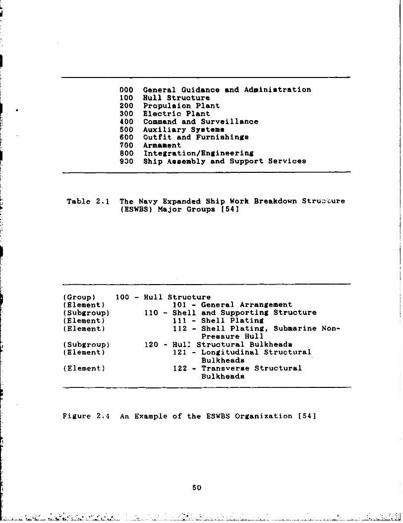
prsduction, and maintenance [ 5 4 ] . All major classification
groups are defined by a three-digit code as described in
Table 2 . 1 , The last two groups are used primarily for cost
estimating and progress reporting. Each major group is bro-
ken down into hierarchical subdivisions called subgroups and
elements as shown in Figure 2.4.
A classification scheme to subdivide work in accord-
General Guidance and Administration Hull Struoture Propulaion Plant Electric Plant Command and Surveillance Auxiliary System8 Outfit and Furnishings Armament Integration/Engineering Ship Asaembly and Support Services
, bure Table 2.1 The Navy Expanded Ship Work Breakdown Stru-" (ESWBS) Major Groups [ 5 4 1
( Group) (Element) (subgroup) (Element (Element
(Subgroup) (Element)
(Element )
100 - Hull Structure 101 - General Arrangement
110 - Shell and Supporting Structure 1 1 1 - Shell Plating 112 - Shell Plating, Submarine Non-
Pressure Hull 120 - Hul: Structural Bulkheads
121 - Longitudinal Structural Bulkheads
122 - Transverse Structural Bulkheads
Figure 2 . 4 An Example of the ESWBS Organization [ 5 4 1

ance with an interim product view ie a product-oriented
work breakdown structure (PWBS) [ 6 6 1 . Part8 and subassem-
blies are grouped by common permanent characteristics, and
classified by both design and manufacturing attributes. The
claseification system typically specifies parameters, such
as form, dimensions, tolerances, material, and types and
complexity of production machinery operations. Classifica-
tion by product aspects relates a part or subassembly to a
zone of a ship and also to work proceaseg by problem area
and by work stage. Therefore, product families are deter-
mined by both design and manufacturing attributes.
Fisst, PWBS divides the shipbuilding process into three
basic types of work: hull construction, outfitting, and
painting, because each imposes its own unique set of manu-
facturing problems. These types of work are further subdi-
vided into fabrication and assembly classifications. Within
the painting classification, fabrication applies to the
manufacture of paint, and assembly refers to its applica-
tion. The assembly subdivisions are naturally linked to
zones and are the basis for the zone dominanoe seen in
shipbuilding management.
Second, PWBS classifies interim products in accordance
with their needs for resources. Resources include material,
manpower, facilities, and expenses,
Third, PWBS classifies interim products by the four
product aspects needed for control of production processes.

Two product aspects, system and zone,, are means for dividing
a ahip design into planned and manageable portionm. Each
zone ia usually addressed by a separate work package. The
other two product aapecta, problem area and stage, are mean8
for dividing the work procesa from material procurement to
complete ship delivery. These four terms many be defined as
follows:
* System - a ~tructural function or an operational function of a product, e. g., longitudinal bulkhead, fire
main system, lighting system, etc.
* Zone - an objective of production which is any geo- graphical division of the total product, e. g., superstruc-
ture, engine room, etc., and their subdivisions or combina-
tions, e. g . , a structural block or outfit unit, a subas-
sembly of either, and ultimately a part or component.
* Problem area - a division of the production process into similar types of work problems such as:
- by feature (e. g., curved vs. flat plat,e, steel vs.
aluminum material, small vs, large diameter pipe)
- by quantity (e. g., job-by-job vs. flow lane) - by quality ( e . 8 . t grade of worker zequired, grade
of facilities required)
- by kind of work (e. g., marking, cutting, bending, weldina, painting, testing, cleaning)
- by anything else that defines a different work problem,
* Stage - a division of the production procemm by aequencem, i. e., mubutepm of fabrication, mubaraerbly,
asrembly, erection, and outfitting.
The claaaifioation syatem and oategoriea described
above are illustrated in Figure 2.5.
After an interim product has been identified by its
product aspects, it ir neceaaary to evaluate its efficiency
as a work package. This efficiency ia a function of the
time it takes to complete the product, the number of units
of resources, and the quality of the work environment (e.g.,
downhand vs. overhand welding). If the efficiency is not
high enough, the work package muat be redefined. This iter-
ative development and evaluation of work packages through
the planning process is illustrated in Figure 2.6.
2.3.4 Planning for Production
In order to successfully include production considera-
tions in preplannin~ or planning, each shipyard must develop
its own build strategy. This strategy reflects the capabil-
ities, practices, and preferences o the yard, modified to
fit the specifics of the ship to be built. It helps to
define and prioritize decisions about the shipbuilding pro-
ject at its earliest stages. An overview of design and
material definition, the importance of overlap of these
stages with production, and their impact on PWBS wili be
treated in this section.

Figure 2.5 Elements of the Three-dimensional PWBS Matrix 1551
Figure 2.6 Iterative Development of Work Packages [ 5 5 ]

Significant overlap of design, material procurement,
and production is essential for reducing the overall con-
struction time, but overlap reduces the time available to
organize information developed by the designers, Therefore,
from the beginning, design information must be formatted to
more fully anticipate needs relating to material and pro-
duction.
In addition to overlap in time, there is an overlap
betweel. functional systems and product aspects. PWBS allows
for this dual grouping. Each phase of the shipbuilding man-
aperient cycle (estimsting, planning, scheduling, execution,
and evaluation) is addressed in terms of system versus zone
orientation.
Figure 2.7 indicates the primary emphasis, either sys-
tem or zone, of each of the phases in the shipbuilding pro-
cess. The process begins with a systems orientation. This
is a view of the ship as a whole, broken down by systems.
During preliminary design the key transformation from system
to zone orientation takes place. Later, near the end of the
contract, the transformation back to a system orientation
occurs to permit overall ship evaluation, in terms of both
systems performance and cost performance. The ability to
make these transformations is key to the successful imple-
mentation of group technology-related or PWBS-related ship-
building.
Design, which is considered part of planning, is

Figure 2.7 System and Zone Orientation in the Shipbuilding Process [ 5 5 1

divided into:
t Basic Design (In Navy parlance thia includes all
design through contract design.)
t Functional Design - up to the detail level t Transition Design - from system to zone t Work Instruction Detail - down to the worker level
These divisions of the design process are described in Fig-
ure 2.8, The design process continues until each zone is
broken down to components that are to be purchased and to
material requirements for parts that are to be fabricated.
This is the lowest hierarchical level of classification.
The most important point is that each successive stage comes
closer to transforming the developing design into a format
better suited to the end users' needs,
Design as well as production groups are organized
according to classes of problems in such a way as to com-
plement the established zones. Each design group prepares
key drawings, working drawings, and material lists in
accordance with the established zones. Within each group it
is essential to have good "horizontal" communication between
the different engineering disciplines. The group focuses on
composite drawings, which show how the ship is to be built,
and material lists. System arrangement drawings are no
longer needed, as the interference-free and simplified com-
posites, either drawings or scale models, are developed
directly from diagrammatics, Therefore, the principles of

Figure 2 . 8 PWBS S h i p Design Process [ 5 5 ]

group technoloay apply to design as well aa to produotion.
Zone-oriented scheduling is necessary to control work
flows so that interim products are produced in such a way
as to anticipate only immediate needs. The scheduling must
coordinate all production work and allow time for the tran-
sportation of inte~im products to the next assembly site.
The goal is to minimize buffer storage while at the same
time creating no bottlenecks or controlling paths. Thus,
integrated schedules are essential for fabrication through
final outfitting and testing.
Shipyards and the Navy desire accurate progress repor-
ting of schedule as well as manpower and material costs.
This is facilitated by having relatively small work pack-
ages. Progress reporting and cost collections are zone-
oriented. This gives both the yard and the Navy accurate
indications of work completed so that work and resources
required for completion can be forecasted. In order for the
Navy (or shipyard) estimators to obtain realistic costs on a
system basis some sort of allocation of costs back to the
system level must be established and agreed upon.
This indirect collection of costs by system may be
viewed as a degradation of system cost data, particularly in
the area. of manpower costs. However, the PWBS philosophy
argues t h ~ t a PWBS-based system produces more accurate data
due to inherently better control. Material usage and costs
can fairly easily be collected by system and cost, particu-

larly where functional designers are required to identify
all materials for each diagrammatic.
2.3.5 Process Flow Lanes
The process flow lane or process lane concept may be
defined as the "categorization and separation of similar
types of work, and the subsequent development of work cen-
ters specifically designed to efficiently perform that kind
of work" [ 5 6 ] . The keys to effective process flow lanes are
planning, scheduling, and material control. The goal of the
shipyard is to establish process flow lanes which produce
repeatable interim products and which are uniformly loaded,
both for an individual shipbuilding program and for other
shipyard projects as well. Figure 2.9 shows process flow
lanes for a notional shipyard. The process flow lanes are
organized by classes or problem areas and demonstrate how
their end products must integrate for zone-oriented produc-
tion. Fabrication shops and assembly shops are grouped
along the various process flow lanes,
Hull construction has historically been the responsi-
bility of a single shop with a single trade union, so the
introduction of hull block construction in process flow
lanes is fairly easily managed in most American shipyards.
However, the establishment of outfitting process flow lanes
and the integration of the entire ship assembly process cuts
across traditional shop and trade union lines. As a result,

m u mcu mcu
4
Figure 2 . 9 Process Flow Lanes in Modern Shipbuilding [ 5 5 ]

progress past the modern hull block construction stage has
been slow in most yards. In shipyards that have completely
adopted zone-oriented methods, many trades have been com-
bined in various ways: a mhip fitter may do some welding, a
pipe fitter may do some electrical work, etc.
2 . 3 . 6 Zone Construction Methoa
The product-oriented breakdown of ship construction
accommodates the following zone-oriented methods:
t Hull Block Construction Method (HBCM)
* Zone Outfitting Methe,\ (ZOFM) * Zone Painting Method (ZOPM)
Also, since large quantities and varieties of pipe pieces,
ventilation ducting, wire ways, etc. are needed, PWBS
accommodates problem area-oriented family manufacturing
(FM), or pipe piece family manufacturing (PPFM). This is
shown diagrammatically in Figure 2,10. The integration of
HBCM, 20FM, and ZOPM represents the application of the prin-
ciples of group technology to shipbuilding. Together they
form a total shipbuilding system. PPFM is different in that
it represents the application of group technology to a spe-
cific shop. For more information on PPFM the interested
reader is directed to reference 2 of Chapter 1. HBCM, ZOFM,
and ZOPM will now be discussed briefly.
Optimum block (or zone) size is the basis for control

Figure 2.10 PWBS Components [ 5 6 ]

in HBCM. But blooka aleo directly impaot gone outfitting
and painting. As a result, the determination8 of block
dimensions and location, compared to other interim products,
have the greatest influence on shipbuilding productivity.
Blocks are designed so that:
t they are assignable to one work paokage group
$ they are inherently stable, balanoed etruotures
t they require minimum working times
$ they have maximum accessibility for outfitting and
painting.
Also, they should be similar in work content as much as
possible so that work can be distributed evenly throughout
the fabrication and assembly levels. Planners and designers
should also try to maximize the amount of downhand welding
and design the blocks to be the largest size capable of
bein# handled by the shipyard's lifting and moving equip-
ment.
It is usually practical to plan hull construction in
seven levels as shown in Figure 2.11. Work assigned to the
grand block level minimizes the duration required for erec-
tion on the ways. For maximum productivity, the main work
flow path must be level-loaded.
Within each level other than the top two, the interim
products are examined for similarities in their product
aspects. Then they are grouped by these similarities in
order to further modularize the production process, justify

Figure 2.11 HBCM Manufacturing Levels [ 5 7 ]

expenaive but highly efficient facilitier, and aohieve man-
power aavinga. Typical grouping. by produot aopeot are
shown in Figure 2.12. Horitontal oombinationa characterize
the varioua types of work paokages that are needed for work
to be performed at each level. Vertioal ombinations of
work packages denote the prooesa flow lane8 for hull oon-
struction work flow which oorreapond to the proceor flow
lanes in Figure 2.9. Maximum productivity is obtained when
work is evenly allooated to work paokagss grouped by their
product aspects, and there are quiok responses to potential
work imbalance, such as shifting workere among manufacturinp
levels and/or process flow lanes, authorieing overtime, or
even short-term schedule changes [ 5 7 1 .
Since both follow the same logic, ZOFM is a natural
consequence of HBCM. Shipyards which have advanced to the
point of using ZOFM assemble most outfit oomponents indepen-
dent of or on hull blocks.
ZOFM planners must consider the block zones previously
defined for hull construction. Then they are usually other-
wise free to devise zones which best suit their system. So,
while there is generally greater freedom in defining outfit
zones, specifying zone by problem area by stage work pack-
ages affords absolute control of work, even in a confined
area of the ship that contains multiple systems. Outfitting
packages which correspond to a zone/problem area/stage orga-

Note: "Nil" indicates no product aspect exists.
Figure 2.12 HBCM Classification by Product Aspects [ 5 5 1

niention are aometimeo ualled pnlleta, Palleta requenoed in
the order they are built make up the rhip'm outfittina plan.
On-unit outfitting refer. t~ a Bone which defiaea an
arrangement of equipment and mupportina rtruoture which i8
assembled independent of hull structure. On-bloak outfit-
ting refer. to the assembly of equipment on any structural
subassembly (semi-blook, block, or grand bloak), On-hoard
outfitting refers to aesembly of equipment during or after
hull erection and launohing. A eone for on-board outfitting
is usually defined by a compartment, shell, bulkhead, or
deck. In general, on-unit outfitting is the safest and most
efficient, followed by on-block outfitting, and finally on-
board outfitting. Every effort is made to minimize the
amount of on-board outfitting.
Maximum productivity is achieved when work is equally
apportioned to work packages grouped by product aspects at
the most efficient manufacturing levels and uniform and
coordinated work flows are maintained, Other oonsiderations
are shifting work, especially welding, from difficult posi-
tions to downhand positions; selecting and designing com-
ponents so as to maximine on-unit outfitting; transferring
work from difficult or unsafe locations to open, spacious,
low, and otherwise safe places; and planning simultaneous
execution of the maximum number of work packages, These
considerations have led to the practice of planning outfit-
ting in six manufacturing levels as shown in Figure 2,13.

Figure 2.13 ZOFM Manufacturing Levels [ 5 7 ]
As in HBCM, interim products with similar product
aspects are grouped to further modularize the production
process, justify expensive but highly efficient facilities,
and achieve manpower savings. Typical groupings by product
aspects are shown in Figure 2.14. It should be noted that
these groupings are for a commercial shipbuilding project.
For a naval combatant the sixth manufacturing level product
aspect area would need to be expanded to include command and
surveillance, and armament. Horizontal combinations charac-
terize types of work packages that are required for work to
be performed at each manufacturing level. Vertical combina-
tions of work package types denote process lanes for outfit-
ting work flow which correspond to the process flow lanes
shown in Figure 2.9. As the use of 20FM increases, the need
for more bal~nced planning and scheduling, and cooperation
among hull construction, outfitting, and painting increases.
ZPTM is a natural consequence of HBCM and ZOFM. Much
of the painting work is transferred from the building dock
or outfit pier to preceding manufacturing levels by inte-
grating paiuting with hull construction and outfitting.
ZPTM manufacturing levels are shown in Figure 2.15. The
prerequisites to successful use of ZPTM are that the paint-
ing interval between one coat and the next coat must be
shorter then the ~Ilowable exposure time for the former
coat; each hull block should be virtually fini-hed in order

Figure 2.19 ZOFM Classification by Product Aspects [55]

Figure 2 . 1 5 ZPTM Manufacturing Levels 1 5 7 1

to minimize surface preparation and painting rework caused
by further cutting, fitting, and welding, and the shop
primers applied to plates and shapes should not impede cut-
ting and welding. Managers must ensure effective accuracy
control to limit the need for surface preparation and rework
resulting from inaccurately made interim products*
The main objectives of shifting painting to earlier
manufacturing levels are to shift position from overhead to
downhand or vertical, from high places to low places, and
from confined to readily accessible places; facilitate the
use of environment-controlled buildings; provide a safer
setting for painting; prevent in-process rust and subsequent
rework; minimize the use of scaffolding; and facilitate
level-loading work throughout the shipyard. Typical clas-
sification of paint work packages by their product aspects
are shown in Figure 2.16. Horizontal combinations chasac-
terize the types of work packages that are required to be
performed at each level. Vertical combinations denote the
process flow lanes for painting work flow.
2.3.7 Accuracy Control
A shipbuilding system based on group technology, using
a PWBS, and integrated hull, outfitting, and painting,
requires good controls on accuracy. An accuracy control
system is initially justified by the need to monitor the
construction of interim products to minimize delays and re-

Figure 2 . 1 6 ZPTM Classification by Product Aspects [ 5 5 1

work during erection. However, when fully operational,
accuracy control forms a major part of the total shipbuild-
ing system. It involves the regulation of accuracy as a
technique for improving shipbuilding produotivity by focus-
ing attention on areas where improvements offer significant
benefits, It also provides the means for monitoring work by
individual work process or problem area. A fully imple-
mented accuracy control system establishes a quantitative
feedback loop between production and planning, design, and
engineering.
The use of the statistical quality control methods
developed by Deming in the 1940's (see Section 2.2) is an
essential element in an accuracy control system. Accuracy
control should not be confused with quality assurance.
Accuracy control is the regulation of accuracy in order to
achieve maximum productivity. This involves a trade-off
between better accuracy and the downstream improvement in
assembly and erection, and the cost to achieve such accu-
racy [ 5 8 ] .
This chapter has provided background and laid the foun-
dation upon which the rest of this thesis is based. We are
now ready to discuss the ways in which modern ship produc-
tion methods have affected naval ship acquisition practices.

REFERENCES m d NOTES TO CHAPTER 2
1. Department of Defenre Directive 5000.1, "Acquiri- tion of Major Defense Systeme", July 13, 1971.
2. Ibid.
. 3. "Ship Acquisition Reef Points", Naval Sea Syatemr Command, February 26, 1976.
4. Ibid.
5 . ' Carpenter, John D. and Finne, Peter C., "Naval Ship Procurement", Naval Ennineerr' Journal, Vol. 84, No. 6, December, 1972.
6. Graham, Clark, "The Navy's Approach to Ship Derign and Acquisition", unpublished gaper.
7. Carpenter and Finne, op cit.
8. Ibid.
9. Department of Defense Directive 5010.14, "Sys- tem/Project Management", May 4, 1965.
10. Department of Defense Directive 3200.9, "Init- iation of Engineering and Operational Systems Development", July 1, 1965.
11. Ibid.
12. Fox, J. Ronald, Arminn America: How the U.S. BUYS Wea~ons, Harvard Business School, Division of Research, Boston, 1974.
13. Ibid.
14. Ibid.
15. Deputy Secretary of Defense Memorandum, "Policy Guidance on Major Weapons System Acquisition1', May 28, 1970.
16. Department of Defense Directive 3200.9, op cite
17. Newcomb, John W. and DiTrapani, Anthony R., "The Patrol Frigate Program - .4 New Approach to Ship Design and Acquisition", Naval Engineers' Journal, Vol. 85, No. 4, August, 1973.
18. Ibid.

19. Department of Defenoe Directive 5000.1, op cit.
20. Naval Material Command Publication P5242, "Joint Design-to-Cost Guide", October 29, 1973.
21. Chief of Naval Operations Instruction 9010.300, "Top Level Requirements and Top Level Specifications for the Development of Naval Ships", January 4, 1974.
22. Ibid.
23. Ibid.
24. Ibid.
25. Fox, op cit.
26. Department of Defense Directive 5000.1, op cit.
27. Department of Defense Directive 5000.3, "Test and Evaluation", January 19, 1973.
28. Newcomb and DiTrapani, op cite
29. Deputy Secretary of Defense Memorandum, "Eatab- lishment of a Defense Systems Acquisition Review Council", May 30, 1969.
30. Department of Defense Instruction 5000.2, "The Decision Coordinating Paper (DCP) and the Defense Systems Acquisition Review Council (DSARC)", February 23, 1973.
31. Department of Defense Directive 5000.1, op cit.
32. Fox, op cit.
33. Program Evaluation and Review Technique is a schedule network analyaia method which determine8 the "critical path" (controlling path of key milestones). PERT reports were required of contractors by Department of Defense Directive 3200.9, op cit.
3 4 , Pox, op cit.
35. Department of Defense Instruction 7000.2, "Per- formance Measurement for Selected Acquisition8", April 25, 1972.
36. Fox, op cit.

37. U.S. Senate, Armed Service Committee, Report 92-359, Authorieinr Defenme A~~ro~rirtion8 f o r Fircal Ye= J97Z.
38. Fox, op cit.
39. Newcomb and DiTrapani, op cit.
40, "Ship Acquisition Manaueaent for Engineerr", Naval Sea Systems Command, 1986,
41. Ibid.
4 2 , Laohica, Eduardo, "Defenre Firm8 Claim Reform8 Hit Them Hard", The Wall Street JournaL, March 16, 1988.
43. "Ship Acquisition Management for Engineera" , op cit.
44. Tibbitto, B. F. et al, "Naval Ship Design - Evo- lution or Revolution?", to be publiohed in Naval Ennineers' Journal, May 1988.
45. Chirillo, L. D. and Chirillo, R e D., "The History of Modern Shipbuilding Method.: The U.S.-Japan Inter- change", The Journal of S h i ~ Producticn, Vol. 1, No. 1, February, 1985.
46. Ibid.
47. Ibid.
48. Chirillo, R. D., "Analytical Quality Circles", University of Washington Shipbuilding Technology Course, Seattle, 3 October 1983.
49. Chirillo and Chirillo, op cit.
50. Ranson, G. N., Grour, Teohnolons: A Foundation for Better Total Com~ans Oneration, McGraw-Hill, London, 1972.
51. Mitrofanov, S. P., Scientific Princi~les of G r o u ~ Technology, English translation by E. Harris, National Len- ding Library for Science and Technology, Boaton Spa, England, 1966.
5 2 . Hyde, W. F., Im~rovine Productivity by Classifi- cation, Codinn, and Data Base Standardieation, Mercel Dek- ker, Inc. , New York, 1981.
53. Storch et al, op cit., Chapter 1, reference 2.

54. m a n d e d Shin Work Breakdown Structure, Naval Sea Syatemm Command, Wrrhington, D. C., 13 February 1985.
55. Okayama, Y. and Chirillo, L. D.. Product Work Breakdown Structure, National Shipbuilding Remarch Program, Maritime Adminiatration in cooperation with Todd Pacific Shipyards Corp., December 1982.
56. Storch et al, op cit.
57. Ibid.
58. Chirilio, L. D., Chirillo, R. D., Storch, R. L., and Nakaniahi, S., ?rocearn A w m i a Via Aoouracs ControL, National Shipbuilding Remearch Program, Maritime Adminis- tration in cooperation with Todd Pacific Shipyard. Corp,, February, 1982.

CHAPTER 3
MODERN SHIPBUILDING
AND NAVAL SHIP ACQUISITION PRACTICES
3.1 ~ o d u c t i o ~
Thia chapter conridorr the consequancer of modern rhi,p-
building method8 on the naval rhip actquirition proaera a8
well a8 the influenoe'the U. 5 . Navy har on mhipyard prac-
tices. The particular areas conridered are deripn and engi-
neerinp, CAD/CAM, ship work breakdown struoturer, and aort
and schedule control systems. It is important to remember
that the information in Seotion 2.3 was presented from an
idealized and generic point of view, am seen by the
researchers and authors of the various National Ship
Research Program's publications. The information presented
in this chapter will relate how real implementations of
group technology shipbuilding in U. S. ahipyards intereot
with the U. S. Navy and its ship aoquioition procers. Thia
will be accomplished in both a peneral way aa well as in a
specific way by considering examples from actual ahipbuild-
ing proprams in specific shipyards.
3.2 Design and Ennineerinp
Section 2.1 of Chapter 2 discussed ship desipn and
engineering as viewed by NAVSEA. Section 2.3 of Chapter 2
discussed this topic from the perspective of a group tech-

nology r hipbu ilder. App lication of group technology prin-
ciple. require8 alteration8 in the conventional rhip darign
and engineering procers. Thir rection provider a derorip-
tion of the design and engineering procerr rarociated with
group technolony shipbuilding, with partioular erpharia on
that portion of the grocear which is under NAVSBA oontrol.
3 . 2 . 1 Qro_uP~eohnols.v Derirn and Enrineerina - Genp-1 Conce~tr
The principal output of the design procerr for a oon-
ventional shipbuilder is a set of detailed plan. and npeci-
ficationn whioh are auitable for ure by any shipyard. On
the other hand, the output8 for a group technology ship-
builder are unique work inntruction packages that provide
specific information for conrtruction organited by the prob-
lea areas defined by an individual shipyard. Also, the mod-
ern proceos must allow for timely identification of material
and production requiremento to enable the rhipyard to pro-
cure, plan, and schedule in a manner consistent with its
management and building strategy. Figure 2.7 ahowed the
management cycle proceeding from system to zone and then back
to a system orientation. Design and engineering follow a
similar pattern. The design stager employed in group tech-
nology shipbuilding were shown in Figure 2.8 and include
basic design, functional design, transition design, and work
instruction design.

In the Navy oontext, bario derign includes the derign
iteratian. up through contract design. This is shown in
Figure 3.1. Significant differencer from oonventional
derign are the elimination of many expennive and time-
consuming syrtem arrangement drawing., identifioation of
outfit work paokagea by product arpects on composite draw-
ingr, the terminology ured, and the orsmisation of derign
rtages. The four design staler are dercribed a8 followr:
Basic Derim deroriber a ship as a total syrtem. It ir
bared on Navy requirement. which fix what the ship is to be
and how it is to perform. The end produotr are rpeoifica-
tionr and contract plans which vary greatly in thoroughness
and detail, depending on the program's aoquisition strategy.
Functional D e m m addresrer each ryatem in quaai-
arranged diagrammatic8 for piping and wiring and in system
plans. These diauraamatics are sufficient for Navy approv-
als and are called key plans. A material list by system
(MLS) is prepared for each keg plan.
Transition Deetp~l regroups information organised by
systems into information organized by zone.. This first
interrelationship of systems and zones, drawn on yard plan.,
is needed for the development of work instructions.
Work Instruction Deainn group8 derign information by
additional product aspects, problem area, and stage, which
are specific to a given shipyard's manufacturing processes.
A material list for fitting (MLF) is prepared for each fit-

I I
i ; I I
. 8108 ; MQCIM. COIIrRACT AND DITA L U D W l l : MSIBN OlllON AWARO DCSlQN ~ U C t l O N 4 0 4
m v I 1
cvwo Group Technology- 1
I
r similar Lo the atove
w I 6
(years )
A - Functional Design B - Transition Design C - Work Instruction Design
Figure 3.1 Conventional vs. Group Technology Deaign and Engineering

ting work inmtruction. A material list for manufacturing a
pipe piece (MLP) or a material list for manufacturing any
other component (MLC) is prepared for each manufacturing
work inatruction [ I ] .
In addition to the altered denign prooeas and the dif-
ferences between group technology shipbuilding design and
conventional design already described, other major charac-
teristics of group technology demign are:
* greater engineering detail is required * design and engineering muat be completed earlier t material definition rust be completed earlier
* greater coordination with production is required t design and auuembly detail. ahould be mtandardieed.
Additionel information muat be provided by engineering and
the design muat take into consideration additional factors.
These include:
* assembly uequenceu * welding oequenoem * toleranceu, exoemo and edge preparation
coatind requirements
t nubamremblg, un' L and block inturfaces
* special tools needed for production * work sites t structural integrity of aubaosembliea, units and
blocks, both upright and upside down
* eupport and pick points for movind and turning nub-

assemblies, units and blocks
* minimization of distortion of nubanremblier, units and blockn during turning and moving.
Some of this information may be provided by other shipyard
groups, such as mold loft, planning, or production, but
greater detail and more documentation is required than for
conventional shipbuilding. Overall, the engineering effort
is more intense in a group technology environment.
The Navy's principal influence in ship design and engi-
neering occurs during the basic design stage. It is there-
fore worthwhile to examine this stage in more detail in
order to discern the interactions that do, or should, occur
between the Navy and its shipbuilders early in a shipbuild-
ing program.
Contract plans and specifications ar.e the output of
contract design, which is the last stage of basic design.
These documents provide a general overview of the ship to be
built and, aa such, represent the ship in a myatems orienta-
tion. Among the documents developed are:
* general arrangements, * ship's lines,
* midship section, * machinery arrangement, * other specific space arrangements, * diagrammatics of major syatems,
8 electric one-line diagrams,
$ contract opecifications.
Also, as part of the feasibility, preliminary, and contract
design processer, normal naval architectural calculations
are performed. Among theae are:
* weight estimates, * longitudinal utrength, * Bonjean curves, * taak capacities, * hydrostatico, * intact trim and stability, * damaged stability, * loading conditions, * wake survey, X resistance,
* electric load analysis, * HVAC analysis, * propeller design, * shafting arrangement. Development of the building strategy is also considered
during basic design. This involves pzeliminary determina-
tion of the block plan, the breakdown for outfitting on-
unit, on-block, and on-board, and the preliminary determina-
tion of the outfit pallet list.
In a preliminary way, basic design:
* defines simple, logical block boundaries,

t defines blocks of maximum size and weight allowed by
the yard's lifting and moving facilities,
t minimizes the number of blocks needed,
t minimizes scaffolding, lifting, and turnovers,
t identifies zone, problem area, and stage claosifica-
tions for organizing work flows.
The block pre-definition mentioned above cossiders how to ,
efficiently fit components and machinery into compartments;
arrange deck machinery, mooring fittings, etc,; and perform
as much painting as possible before hull erection.
Basic design is also concerned with the development of
procurement specifications for long lead time and other
important outfit items. These include main engines, power
generating equipment, electric motors, steering gear,
nuclear propulsion equipment (in the case of a nuclear-
powered ship), and combat. system equipment [ 2 1 .
3.2.2 Group Technolous Design and Enuineerinu - Exam~les
We have seen that there is an intensification of the
engineering effort in a group technology.environment. Table
3.1 summarizes thia effect for the Navy's TAO 187 shipbuild-
ing program. The numbera for conventional construction were
estimated through discussion with Avondale Industriesp Ship-
yard Division chief engineer during the TAO 187 program [31.
The group technology-related numbera were provided by Avon-

Conventional Group Technology Conrtruotion Con8truation
Total engineering man-hours 820,000 740,000 Percent comtlete at
fabrication start 40 80 Months from contract to
fabrication start 19 17 Man-hours per month prior to
fabrication start 10,900 34 800
Table 3.1 Engineering Effort. for the TAO 187 [31[41
Figure 3.2 Avondale Industrier' Design and Construction Methods, Conventional ve. Current [ 5 ]

dalega Program Services Division. [ 4 ] As can be seen in
thia table, the intensity of the engineering effort more
than tripled with the application of group technology meth-
ods* Figure 3.2 further demonstrates thia. Of courre, the
extra expenoe involved in this higher intensity effort is
worthwhile only if savings greater than the extra engineer-
ing expense are realized in the course of the production
effort. The shortened production period and earlier deliv-
ery date shown when using Avondale'e current methods indi-
cate this was indeed the case for the TAO 187. See Figure
3.2 for details.
Theoretically, most or all of basic design should be
completed prior to contract signing. This poses a problem
for naval ship acquisition managers since the shipbuilder is
not determined until after contract design is completed and
much of the work done during basic design assumes a specific
shipbuilder has already been selected. Attempts were made
to solve this problem in the DDG 51, SSN 21, and TAGOS 19
programs and these will be discussed later,
The machinery arr~ngement drawings for the TAO 187 were
provided as oontract nuidance drawings and required modifi-
cations to suit Avondale's construction methods and produ-
cibility improvements. These changes included:
t revisions to suit the main engine purchased in lieu
of the engine assumed in the contract guidance drawings,

* revisions to built-in tankage to s opments,
~uit system devel-
improved functional grouping of auxiliary syatema and
components,
: development of package unit boundaries to auit ove-
rall arrangements and conatruction sequence,
: minimizing equipment mounted directly on ourved side
shell,
: integration of ventilation and wireway routinga into
space arrangementa,
: integration of accesm and handling of main engine
special tools and spare. into apace arrangementa,
t detailed development of aystema to enable racking of
pipe rur.8, grouped deck and bulkhead penetrations, etc. 161.
Conoideration of accessibility for operation and main-
tenance of all components throughout the ahip'a life was a
primary objective throuuhout the design proceam. Thin oon-
sideration was consistent with basic shipyard producibility
conaiderationa in that the greater the ease of acoeasibility
in the ship the greater the shipyard productivity.
Table 3.2, summariees the rssulta of various producibil-
ity and produotivity measurea undertaken in the machinery
spaces of the TAO 187. It ahould be noted that some weight
inpacts are positive and some are negative. Althouah no
proof was offered, it is Avondale's position that the sum of
the weight impacts did not adversely affect the ship [ 7 3 .

Attribute
Weight
Pipe Footage
Accessibility
Operability
Maintainability
Conotruction Cort
Construction Schedule
15% increase in foundation weight
5% decrease in piping footage
Improved
Improved
Improved
15% - 20% reduction Machinery Spaoe Bquip- ment and System Inrtallation not on the critical path of ship oonatruction
Table 3.2 TAO 187 Machinery Space Demign and Construction Rerulta ( 7 1
When moat or all of the drawings in the NavyJr contract
deaign package are provided for "guidmoe only", the con-
tractor ham the maximum latitude for developing the detailed
deaign that beat acoommodatea him build atrategy and ship-
yard oapabilitiea. However, there i m a growing trend for
the Navy to make drawings in the contraot demign paokage
contract documents. Thia war true in the LSD 44 program and
is now true in the A06 6 program. Suoh drawinge, which have
not had the benefit of producibility oonaiderationa, will
result in higher nhip oonrtruction ooatm, and possible oper-
ational limitations and contractual diaputes.
In some programa the Navy ham tried to core to grips
with this problem. Thane programa include the DDG 51, SSN
21, TAGOS 19, and L S D 44 (Cargo Variant) programs. For the
SSN 21 basic design phase there were only two qualified
shipyards and both participated heavily in preliminary and
contraot design. For the L S D 44 (Cargo Variant) proarm,
NAVSBA awarded a oontraot for contract design to Avondale
Industries. Yroducibility, at least from AvondaleJr per-
spective, was thua asoured to some degree. But sinoe thin
ia basically a modiffad repeat design, there are utill many
of the original oontraot drawing problemn. Also, AvondaleJs
final design product had to be sufficiently general to
ensure other shipyard8 could bid on the detail design and
conatruction contract on a competitive baaia with Avondale.
In the DDG 51 program, a great deal of induetry input

war requerted prior to and during oontract derign. The var-
ioua contractorm were corpenmated for their efforts, but
only at a minimal level. Moat rpent far more than they were
paid for their effort*, conaidering it a calculated buminerr
investment. In the end, one oontract demign paokage waa
developed and it incorporated many produoibility idea., but
due to the competitive nature of the fsllowinp detail derinn
and conatruction contract, no one mhipyard'r proposals could
be excluaivsly followed in the producibility area. A180 in
spite of the open and generally produotive atmosphere the
DDG 51 contract design was conducted in, it ir probable that
some shipyards kept some of their beat producibility ideas
to themaelves and would have inoorporated them into the
design only after winning the detail design and conmtruction
contract.
In the DDQ 51 program two of the main basic deaign par-
ticipants, Bath Iron Work. and Ingalls Shipbuilding Divirion
of Litton Induatries, won the lead and follow yard con-
tracts, respeotively. In the T A W S 19 program, the basic
desi~n was carried out in a manner similar to the DDG 61's.
However, none of the seventeen initial participant. in the
basic denign yrooesa won the competition for the detail
design and construction of the firat ship. This rituation
will certainly not encourage shipbuilders to use their best
talent to assist in similar basic designo in the future,
especially when the compensation provided in these programs

has been minimal.
3.2.3 p r o u ~ Teo~olofl~ D e u and Standardieation
Standarditation is the prinoiple of demign for produc-
tion that oould theoretically lead to the greatert improve-
mentr in productivity ( 8 ) . The diacuasion of group tech-
nology and PWBSr ham emphamieed the oonoept of orgmieation
of work by problem area. The ultimate goal is to develop a
group of mtmdard building blookr that oan be combined to
produce very different final productm.
Efforts at atandardisation are umurlly conoentrated at
the component, mubamsembly, block, and outfit unit levels.
Standards may be olasrified in two groupu (91. Theae are
basic standards and mtandard drawingm. Bsmio mtmdardm
include material and component rtandardu, outfitting atan-
dards, demign standards, production engineering standard.,
and inmpection atandards. Standard drawingm show typical
subassemblies and outfit unita that may be used direotly on
new designs or as guidanoe in preparing new drawinpa. Fig-
ure 3.3 organizes thir clamsifioation of atandards in aore
detail.
Figures 3.4, 3.5, 3.6, and 3.7 are simplified examples
of standard drawings for a struatural subassembly, machinery
arrangement, piping layout, and outfit unit, respectively.
The widespread uoe of standards is easier to realize in

Figure 3.3 Clasaifioation of Standard. [ 9 ]
Figure 3.4 Standard Structural Asaenbly Detail [ 8 ]

Figure 3.5 Standard Machinery Arrangement Module [ 8 ]
Figure 3.6 Standard Piping Layout Module [ 8 ]

Figure 3.7 Standard Outfit Unit Module [81

commercial ship design and construction than in naval ship
programs. Over the years numerous Military Speoificationti
(MILSPECa) and Military Standards (MILSTDe) have been devel-
oped and routinely invoked in shipbuilding contracts. At
the time each was developed it responded to borne real or
perceived need which resulted from a battle caaualty, equip-
ment failure, personnel casualty, or similar problem.
Unfortunately, over the years not muoh effort has gone into
reviewing these MILSPECs and MILSTDs for current ueefulness
and they have proliferated to the point where the whole sys-
tem has become unmanageable and to oome extent, outdated.
There are numerous examples of MILSPECs which are still in
effect simply because they proved useful decades ago. Few
attempts have been made to update them after new materials,
technologies, or processes became available.
If, for example, a shipbuilder wished to use some new
structural detail or welding process whioh would enhance
producibility and reduce conatruction coats, the mhipbuilder
would typically bear the responsibility, risk, and coat for
shock qualifying or otherwise obtaining approval of the new
detail or process. And then, even if this is done, the
approval is typically restricted to the alas8 or type of
ship for which the approval wss originally requested. In
such an environment, where contractors have little incentive
to improve the system, it is nGt surprising that attempts at
achieving standardization are few [101.

3.2.4 u n Ch- ~ o u i Enrineerinn Envj,ronment
Design changes in naval 8hip acquisition programs are
very common. In fact, to deal with the large valume of
changes frequently encountered in a major combatant program,
the Navy has developed an extenuive mystem which is more or
less standardized aoroas various ahipbuilding programs.
Design changes ocour for a variety of reaaonm and
can be broadly broken down into two categories: changes that
occur due to Navy actions and change8 that occur due to
contractor actions. Theae include:
* Navy - correction of errorn diecovered in specifications
or contract drawings
- correction on follow ships cf problems uncovered dur- ing operation of the first ship of a class
- the desire to continually incorporate the latest technology in combat systems and other ship systems
- different thinking and new preferences that develop over time
- application of new rules and regulations - new interpretations of existing rules and regula-
tions
- application of recommendatione received after con- tract award
8 Contractor
- revised fitting stager - revised equipment or component locations - revised manufacturing process - revised material availability or souroea - revision of hull structure - resolution of a design reservation,
A number of contractor changer are the inevitable result of
the calculated riak of allowing each of the outfit design
groups to sinultaneoualy conduct functional, transition, and
work instruction design. Certain ampects of the design
progress conditionally, pending the remolution of interfer-
ence problems.
There is no doubt that group teohnology mhip devign and
construction is a much more change-intolerant environment
than conventional shipbuilding wam. This im an anticipated
and natural oonsequence of a system that require. much mere
documentation and, at the work inatruction level, much more
paperwork in order to construct a ship. Alro, the timing
and intensity of the engineering effort tend to make deaign
change8 more expenoive and have a greater impact on the
total effort. This greater expense and impact on the ship-
building program is justified only if the downstream saving.
in ship construction coats and shorter construction ached-
ules more than compensate for the greater expense and impact

of design ohanges.
In the TAO 187 program a special effort waa made to
hold the number of contract change. to a minimum, Items that
were "nice to have" but not essential were not considered.
Also, since the TAO 187 is an auxiliary rhip and not a com-
batant, there is less of a conoern with achieving the state-
of-the-art. There is a180 traditionally less Navy oversight
of auxiliary ship program and so there are fewer possible
inputs for changes. To accommodate the! few ahanges that did
occur (in the neighborhood of 100 1111) a streamlined change
control process was instituted. This mainly involved the
NAVSEA program office giving more authority to the local
Supervisor of Shipbuilding, Conversion, an,d Repair office
for negotiating contract changes. As a result, the impact
of changes on the TAO 187 program was minimal and the first
four ships of this class were delivered on echedule and at
or under budget. This was true even though Avondale Indus-
tries has possibly the most advanced implementation of group
technology shipbuilding in the U. S. and is therefore pre-
sumably the most change-intolerant.
In the CG 47 and DDG 51 Aegis shipbuilding programs the
impact of changes has been much more severe. The CG 47
program has had literally tens of thousands of che- ',s to
date. The large number was mainly due to the parallel
design efforts involved in the shipbuilding program and the
Aegis combat system development. Since the combat system

was planned for inatallation in an eximting hull (DD 963
demign), the numbev: of changea wa. actually Zems than other-
wise might have been 3xpected. The effect. of theme changea
on the contractors' shipbuilding ayrtemr were mitigated by
the fact that neither Aegim hipb builder had a fully devel-
oped group technology-related system at the atart of the
Aegis shipbuilding program.
The same conditions do not exist in the DDG 51 programi.
This program feature. a new hull d ~ r i g n ooupled with the
existing, but still very much developing, Aegis combat sya-
tern. The number of contract changea are expected to rival
that of the CG 47 program. To study the pote~tial impact of
these changes, a study was made of repreaentative changea in
the CG 47 and DDG 51 programs at both Bath Iron Wsrks (BIW)
and Ingalls Shipbuilding (IS). The purpome of the study waa
to obtain some measure of the engineering impact of changes
in a group technology environment.
BIW claims to have essmtially a fully implemented
group technology shipbuilding system for the DDG 51 program,
while IS'S system ia not so fully developed. The changes
selected far evaluation were from among those that were
essentially the same for both the CG 47 and DDG 51 programs
from a production and ship impact standpoint. This allowed
fol. the comparison of engineering man-hours between the same
changes in the two yards to be used as a valid basis for
measuring the differences between the two yards' engineering

. 1 . . .. , i ' .
department..
The changer oonridered wore:
8 addition of a lisht to the Offioer of the Deok's
(OOD'r) stand on the bridge
8 increaring power of the weapons pallet truok by
changing the power supply voltage from 12 to 24 volt8
8 replacing the exirting rudder rtook seal with a new
type of seal to prevent leakage problem
8 changing the uontrol ryrtem for the ship*. vertical
paakage conveyor ryrter
t permanent inrtallation of a strain gage mhaft align-
ment syrtem
8 changing the garket material in more fuel oil and
lube oil piping [121.
Table 3.3 given an indication of the engineering impact of
these changes in a group technology angineering environment.
No multi-ayatem, single zone uhange was found. Such a
change c m l d be the addition of a damage oontrol locker to
the ship. One gone might be affected but nu~nerous piping
and electrical system8 would need do be rerouted to maks
room for the space.
A multi-system, multi-eona change will generally have
the areatest impact on the engineering effort in terma of
man-hours required to process the change in a group tech-
nology engi.neering environment. For this reason the gasket
material change will now be considered in detail. It must

OOD light
Pallet tru,ck
Single Multi- Single Wulti- System systsm System myrtem
Single Singla Multi- Multi- Zone Zone none Zona
Rudder mtock x aeal
Vertical package conveyor
Strain gage
Gaaket material
______c. Diredtion of greater engineering impa0.t
Table 3.3 Engineering Impact of Selected Chaneem in the CG 47 and DDQ 51 Shipbuilding Programs (121

be remembered that thim analymim appliem to only the engi-
neering portion of the ohanae.
In April of 1985, NAVSBA direoted thm replraerent of
ambeator-filled mpiral-wound gamketm with non-ambemtoa spi-
ral-wound paper/ehlorite AMFU gamketm for raimed-flange
applicatianr (131. Unfortunately, t h e m gadwtr leaked when
umed in fuel and lube oil rymtemm. Bventually, after par-
tial terting, a decidion wrm made to ure non-ambemtom mpi-
ral-wound graphite-filled gamketr. It im intererting to
note that teat remultn did not oonoluaivelp oonfirr that the
graphite-filled gamketm will 8 0 1 ~ s the laakage problem and
another solution ray need to be found in the future.
From a material mtandpoint thir ohange mirply involver
substituting one type of narket for another. The number of
gaskets totaled 1415, of 57 different types, ranging in mite
from 1/4 inch to 10 inchem. From a produotion mtandpoint,
the installation of there gamkatm may prove more difficult
than for the arbemtom-filled oner. Thim i n beoaume r higher
quality flange face finimh, truer pipe alignment, and
gre7ter torque are required to enture leak-free operation.
Generally, theme material and production arpectm are of
equal conmequence to both yards. However, the engineering
effort, in term. of man-hours required to implement thir
change, varies considerably from BIW to IS.
Table 3.4 gives a breakdown of the engineering-related
man-hours required to implement this change at BTW. A mimi-

Number of Emtirated Doaumn t r Man-hourm
"Drawings" 18
CAD doouuentr and file8
Supervirion and rtaff
Checking
Production, planning, and oontrol
Finanoe and administration
Adrinimtrative
TOTAL, . , . . . . . . . .5,274 ran-hour8 or 2.54 man-yearm
Notea: "Drawings" inoluder aotual drawinga, BIW engineering mtandardr, and other engineering documents.
CAD doouments and filer includes CAD rymter ohmger, computer data met models, and material liotr.
Table 3.4 Engireering-related Man-hours for the DDG 51 Spiral-wound Gasket Biller Material Change [ 1 2 ]
10E

lar breakdown war not available for IS but tne total number
of engineering-related man-hourr required to implement thia
ohange war approximately 10% of the tatal ahown in Table
3.4. Thir large differenoe for ms*ntially the rare engi-
nearing change ir mortly attributable to BIW'r CAD implemon-
tation and the expenme of altering and rmiaruing nunerour
doourents at the detail work inrtruotion level. Similar
difference. for other ohanger are oouon in the Aebia pro-
gram and account for the rkaptical attitude toward group
technology shipbuilding exhibited by momm hais progru per-
sonnel. It i r the opinion of the Teohnioal Dirmotor for the
DDG 51 shipbuilding program that more oonventional ahip
deaign rethodm should be uued for major ooabatants, at leart
for the firat feu shipr of the olars. Then, after rort
changer have been prooerred, a more eoonomiorl transiticn to
the work instruction ;eve1 of detail oould be aooorplimhed.
While this approach might reduce the coat of the engi-
neoring portion of ohanger and rake them earier to rooept
politically, it might also have the effeot of inoreasing
rhip production coot.. The oomt of engineering changes murt
be evaluated in the context of the entire shipbuilding pro-
gram.
3 . 2 . 5 G r o u ~ Technolon~ Deairn Product%
It has been mentioned previously that with the advent
of group technology design and engineerinl, shipbuilders

have been freed from the need to develop individual detail
syrtem arrangement drawingr, This har oauaed great concern
among rome reotorm of the NAVSEA rhip derian oouunity ( 1 4 1 ,
Traditionally, detail ayrtem arrangerent drawinas have been
u8.d for planning future rhip alteration (SHIPALT) and over-
haul work paoka#erb With these drawing. no longer developed
by the mhipbuilder, aore rgrtemr engineerr believe they will
not have the resouroes required for adequate SHIPALT and
overhaul planning. However, the information typioally con-
tairied in detail myatem arrangement drawing. can be found in
detail tone arrangement drawing.. In addition, other infor-
mation not tenerally found on detail syrtem arrangement
drawing., auoh am ryrtem interferenoem, ir available. Am a
result, detail gone arrangement drawingr may prove to be
more ureful as planning doouments than detail syrtem arran-
gement drawing.. The bigpeat problem will be overooring the
inmtitutional mindret that believer detail ayrtea arranga-
rent drawings are neceurary [ 1 5 ] .
Another problem is conoernsd with the format of eone
drawing.. At this time each rhipbuilder haa hia own method
of developing them. Typically the drawing. include redun-
dant information with both the Navy'. and the contractor's
nomenclature included. And in rome caraa, too many syatems
are included on one aheet of the same drawing. All of this
results in cluttered and difficult to read drawings. In
order to alleviate there problem. the Navy need8 to develop

a standardized zone drawing format and invoke it in ship-
building contracts, as MILSTD 100 and MILSTD 1000 are now
invoked [16][17].
3.3 CAD/CAM
Computero were initially uaed in the shipbuilding
industry aa accounting tools. Their application has
expanded dramatically over the years and the many current
uses of the computer in shipyards has expanded beyond the
capability implied by the term CAD/CAM. A list of modern
computer-aided functions could include:
* computer-aided design (CAD) * computer-aided drafting * computer-aided engineering (CAE) * computer-aided manufacturing (CAh) ? computer-aided material definition
t computer-aided process planning (CAPP).
Other than the above items, computer applications in ship-
building have grown to include:
* estimating * accounting * purchasing t numerical control (N/C) operation8
t robotics
? accuracy control
t quality assurance

t inventory control.
As a result, the term CAD/CAM may be somewhat misleading. A
more descriptive term in computer-integrated manufacturing
(CIM). The major problem now facing shipbuilders in the
application of CIM is the lack of a unified shipbuilding
data base that provides the capability of interfacing with
all the applications mentioned above [ l a ] . The relationship
of the data base to the design cycle and its outputs is
shown in Figure 3.8. Information required in the data base
incltrdes :
t numerical and go~!?etrical data on past designs
t weight and space ocaling relationships
t systems and equipment
* structural design data t resistance and propulsion data
* cost data * typical block plan8 t typical outfit plans
* shipyard and military standards and specifications t material lists.
Implementation of a CIM system permits the evaluaticm
of additional design options aa well as consideration of
alternate building strategies. Computer-generated plans,
lists, and work instructions may be used for the various
design cycle stages as well as for shipbuilding management
functions.

S ~ I P Y M construc? ron I
nunan ICAL COMTROL t o r t IHB two urrs
AND WUK iNSIIUC: ION3
Figure 3.8 The Relationship of a Shipbuilding Data Base to the Ship Design Process ( 191

The ultimate goal of a CIM system is improvement
shipbuilding productivity, Among the manifestations
increased productivity are:
* the ability to produce concept and feasibility design studies more quiokly and accurately
ship
* the ability to rapidly evaluate design options and choose the optimum one
* the ability to perform design calculations with greater confidence due L O having a proven data base
t the ability to transfer data in digital form to ship-
yard design offices and manufacturing facilities
t the ability to establish and use shipyard standards.
A coordinated system should lead to simplification of all
aspects of the design and production proceas. See Figure
3.9 for a descriptive summary.
A recent attempt to improve the state-of-the-art in
CAD/CAM implementation has taken place in the SSN 21 pro-
gram, NAVSEA, together with the Electric Boat Division of
General Dynamics, Inc. and Newport-News Shipbuilding and
Drydock, Inc. have implemented the National Bureau of Stan-
dards Initial Graphics Interchange Specification (ICES) on
the detail design of the submarine. Thia allows the two
shipyards, with their different and normally incompatible
brands of CAD/CAM equipment, to exchange a11 formr of digi-
tal data between their two deaign uapartmenta.
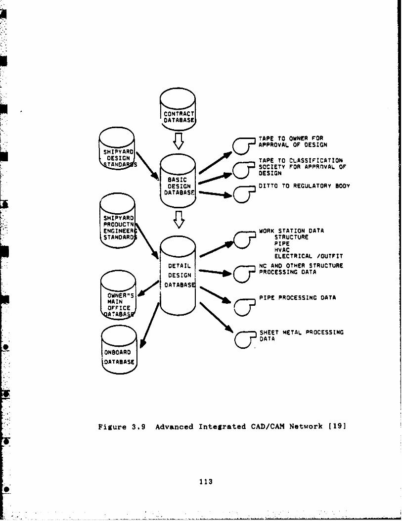
CONTRACT OA TABASE
OESIGN OAT ABASE
PROOUCTN ENGINEER STANDARD
I DETAIL 1 DESIGN !
TAPE TO OWNER FOR APPROVAL OF DESIGN
TAPE TO CLASSIFICATION SOCIETY FOR APPROVAL Of OESIGN
OITTO TO REGULATORY BOOY
WORK STATION DATA STRUCTURE PIPE HVAC ELECTRICAL /OUTFIT
NC AN0 OTHER STRUCTURE PROCESSINC DATA
P IPE PROCESSING OATA
SHEET METAL PROCESSINC DATA
Figure 3 . 9 Advanced Integrated CAD/CAM Network 1191

As mentioned earlier, a fully developed CIM aystem
requires the development of a unified shipbuilding deta
base. Part of thio development involves the preparation of
a "standard library" which cont~ins a considerable level of
information covering standard outfit items. This library
requires many man-hours and is a task unto itself, necessi-
tating verification prior to using it to prepare interferen-
ce-free workxng drawings. Experience has ahown that, while
optimistic forecasts of advanced CAD/CAM installations have
eventually been successful, they have not very often been
put into service within their required schedule 1201. Such a
realizatio~~ caused the project team for the Service Life
Extension Program for the USS Kitty Hawk (CV 63) to modify
its original plans for use of group technology on the pro-
gram [211.
CAD/CAM projects currently being pursued within the
Navy generally fall under the cognizance of the DoD program
known as Computer Aided Log:-stic Support (CALS). CALS was
initiated in 1985 by the Deputy Secretary of Defense in an
effort to achieve major improvepnts in weapon system
designs, and to improve the accuracy, timeliness, and uoe of
logistic technical information. The ultimate goal is to
move from current paper-intensive weapon system support pro-
cesses to a largely automated and integrated system 1221 .
Figure 3.10 provides a graphic presentation of a notional

CALS system.
NAVSEA has identified two intermediate goals in support
of CALS. They are:
* identify and specify the digital products that are to be received at the conclusion of each ship acquisition and
support phase and
* have the facilities and software in place to receive those digital products and use them as the basis for all
support activities 1231.
The principal technical problem to be solved is finding
a way for computer communication links to be made among the
varied and numerous participants. Figure 3.11 shows a flow
chart of the CALS process, The lettered arrows are the
communications links. A joint industry/Navy committee has
been formed to research this problem. It is called The
Navy/Industry Digital Data Exchange Steering Committee.
Demonstration data transfer projects are currently underway
in the DDG 51 program and, as already mentioned, in the SSN
21 program. These programs have been mainly concerned with
the links lettered "A" and "B" in Figure 3.11.

POLLOW VARO
MCBUILMR CUWwO VARO . 8WOINIRI)IIM
I.. CAM MYQW omar
C ~ U c t YOOIL CnOOVct YOOIL
Figure 3.10 Notional CALS System [ 2 3 1

Figure 3.11 Principal Data Transfer Interfaces in a CALS System [ 2 3 1

3.4 && Br-down S$ructurep ( W m l and Coat QghpdulaCont-
Navy rhipbuildins contracts routinely call for WBSr
and require that they oonform with MILSTD 881A, which is
entitled "Work Breakdown Struoturea for Defense Material
Itema". In addition, shipbuilding contraotr frequently
reqi~ire adherence to 'urther Navy-def ined WBSs. Two that
are currently invoked are oalled the ship work breakdown
ntruoture (SWBS) and the expanded ship work breakdown
structure (ESWBS). ESWBS was briefly described in Seation
2.3.3. Their moat important feature is that both are organ-
ieed along functional or ship symtem lines.
The WBS that makes the moat sense for group technolopy-
oriented shipbuildera, however, is a product oriented work
breakdown structure (WBS). Thia was described in detail in
Section 2.3.3. Further, Chapter 32, Part 196 of the Code of
Fedoral Regulations, entitled "Work Breakdown Structures for
Defense Materirl Items", requires that government contrac-
tors have complete flaxihility in extending the generic WBSs
described in MILSTD 881A (mee Appendix A) to reflect how the
contractoy's work is to be accomplished. This has led nome
people, both shipbuilder and Navy personnel, to cmtend that
the Navy-impoeed SWDS and ESWBS are therefore, at beat,
unneeded documents, and are, at worst, illegal documents
[ 2 4 1
If this conflict between Navy requirements far- a tra-
ditional system-oriented WBS and contractor requirements for

a product-oriented WBS, which reflect. the way the ahip is
aotually conrtructed and ranaaed, ia not resolved, ahip-
builderr will oontinue to manage by one ayatem and report to
the Navy by another, The iaefficienciea and inaocuraciea
that reault are not only expenrive but alao lead to the Navy
not being able to adequately monitor coat and schedule
progress.
The Navy's SWBS war originally iaaued in March 1973 as
a atruotured nyatem (3-digit numbera providing 5 levels of
breakdown) which was intended for uae in apecification pre-
paration, ocrt estimating, coat progressing, management,
weight control, drawing numbering, ahipyrrd job order cod-
ing, and similar purpoaea. ESWBS provideo two additional
levels of breakdown of funotional mymters so that ESWBS oan
be used for logistic support, maintenance, and life cycle
support purposea. ESWBS ia now being specified oontractu-
ally and is used aa the basis for C/SCS reporting. Appendix
B provides more details.
A s demcribed in Section 2.3.3, the PWBS was developed
to support group technology shipbuilding. A8 such, it pro-
vides a natural breakdown for rchedule reporting and for
collection of financial data as required by C/SCS instruc-
tions. A shipbuilder's PWBS is hardware or product-
oriented, and is consistent with the methods of planning,
scheduling, and construction actually being used by the

shipbuilder. Appendix C provider further detaila.
Effeotive management oontrol muat be baaed on the itear
or product8 produaed. The PWBS ured on a partioular ahip-
buildinu program ahould be baaed on the produots produced
and on the coding ayatem used within the shipbuilder's man-
agement atructure, For example, on the LSD 44 program at,
Avondale Induatriea, Ino., ahipa are fobrioated by arammb-
ling unit8 whioh are numbered from 000 to 799. The unitat
looations are uaually determined by the diait in the
hundredDa column. Material ir mchduled and as8eabled by
unit number m d work ia budgeted and authorized by unit. or
aroupa of unita. The unit number ia the fooal point of the
PWBS and unita are eaaily auurrrised by aerier: 100, 200,
etc., for reporting purpoaer. Where there is a prooesa or
effort which tapana unit boundariea, the definition of MILSTD
881A are w e d to define there efforts and are auuarited at
the series level for reporting, Other activities such a8
testing, program management, or other aervioes are airilarly
summarized to coincide with MILSTD 881A definition. at lev-
els 2 and 3. All of the reporting ia developed and used to
manage, control, and report financial status direotly from
the labor and material coding used in Avondale'a accounting
system. If reporting was done baaed on an ESWBS syutem, the
information would somehow have to be back-allocated into the
tradition31 functional or eyrtem categorier. Thin would be
needlessl2 time-consuming and probably inaccurate for both

rchedule and cart reportin#. Fi8ure 3.12 depiotr the phyri-
cal rhip elerentr of the LSD 44 program oontract WBS and
Table 3 . 8 demoribem a11 ruuary elerentr. Figure 3.13 im a
portion of the programma rerponribility arrignment matrix
(RAM). The element numberr in the matrix indioate muuary
work packale numberm. A review of the RAW quiokly dirolores
which work group (with the name of the oorreapondina work
group superintendent) is rerponrible for itr portion of the
work in a particular tone or within a partioular elemant.
The initial rtepm to rerolve the oonflictr between
rhipbuilder and Navy derirer regardin8 WBSr have been taken
1271. At an indurtry oonferenoe on WB9r attended by repre-
sentatives of variour mhipbuildwr, NAVSEA, ASN(S&L), and
the Office of the Seoretary of Defenre (OSD), a deoimion wam
made for the indurtry confereem to rubmit their requested
reviaion8 of MILSTD 881A to the Navy and OSD for review. An
ad hoc induatry eoarittee war formed m d prepared a proposal
which war submitted to reprementativer of OSD, ASN(S&L), and
NAVSEA at a follow-up meeting on September 24, 1987 tS81 .
The recoauendationa were well-received by the government
attendees and a formal rerponre to the industry porition was
promised by October 28, 1987. Unfortunately, the Navy has
been unable to obtain the approval of the other services for
the proposed changes to the MILSTD. This stems from the
other services' reluctance to approve a WBS which allows

Figure 3.12 LSD 44 Program Contract WBS Physical Elements ( 2 5 1

Contract WBS Element or Zone
Ship Assembly
Includes unita whioh are special fabrications installed through- out the ship. Work under this element includes material, man- power, inspection test, super- vision, and the effort to in- stall government furnished equipment.
I:,:cludes unita between frames 43 and 98 and baaeline to the 02 level.
Includes units between frames 98 and 137 and baseline to the main deck level.
Includes units between frames 13.2 and 43 and baaeline to the 02 level.
Includes unita between frames 13.2 and 92 and above 02 ljvel.
Includes unita between frames 92 and the stern and above the main deck.
Includes unita between frames 137 and the etern and from baseline to the main deok.
Includes units between the stem and frame 13.2 and from base- line to the main deok.
Includes efforts and material associated with the ship as a whole and which cannot be identified with other zones.
Table 3.5 Description of Ccntract WBS Elements for the LSD 44 Shipbuilding Program [ 2 5 ]

Contract WBS Element or Zone
Description
Integration/ Engineering
Program Management
Test and Evaluation
Data
Spares, Support, Jigs, and Dies
Includea labor and material for the design of the ship.
Includes efforts and material to provide management necessary to ensure comt, schedule, and technical performance under the contract.
Includes efforts and material to conduct all testing for the ship.
Includes all deliverable data to be submitted, as lirted on contract data requirements list.
Includes effort8 and material necesaary to procure, handle, and store spare components, assemblies, repair parts, and special production equipment, etc.
Table 3.5 Description of Contract WBS Elements for the LSD 44 Shipbuilding Program [ 2 5 1 (continued)

Figure 3 . 1 3 A Portion of the LSD 44 Program Responsibility Aesifinment Matrix [ 2 6 ]

for transitions from a syatem to a zone and then back to a
syatem orientation. Even within the Navy there is opposi-
tion to this process because of fear that every shipbuilder
would try to avail itself of a unique cost performance
reporting system. It appears at thia time that the use of
MILSTD 881A as the vehicle to establish the so-called "two
track" .reporting system may not be feasible, Nevertheless,
ASN(S&L) and NAVSEA appear committed to finding a wny to
facilitate the use of a PWBS. NAVSEA is preparing an
internal decision paper on the issue and it is expected in
the very near future.
3.5 Learning Curve Effects in G r a m Technoiopy Shipbuilding
It is widely believed that the group technology
approach to shipbuilding is worthwhile for even cne-of-kind
ships, And, of course, as more ships of the eame class are
built, further savinge accrue due to decreased production
costs. But does the data indicate these savings are con-
stant or is there any evidence that savings continue to
increase as the number of ships produced increases? In
other worda, does any "learningtv take place? To help answer
this question, the TAO 187 shipbuilding program at Avondale
Industries, Inc. was considered. Table 3.6 shows the
results of examining the cost data summary reports p~epared
for the TAO 187, 188, 189, and 190. It is clear that some
slight benefit arises from series production. As was noted

S h i ~ Recurring Produotion Costg
TAO 187
TAO 188
TAO 189
TAO 190
Note: Data are reported on a relative basis with - the recurring costs for the TAO 187 set arbitrarily to 1.000. This was done due to the proprietary nature of the cost data.
Table 3.6 Recurring Ship Production Costa for the TAO 187 Program ( 2 9 1

earlier, few changes were made during the courae of this
shipbuilding program. This is the only military shipbuild-
ing contract that has been completed and has used the group
technology approach from beginning to end. (More TAOs are
being built under new contracts.) It will be interesting in
to analyze the return costs for other shipbuilding programs
at other shipyards in the future to see if there i o evidence
of this slight learning trend or if there are more dramatic
results.

REFERENCES TO CHAPTER 3
1. Storch, R. E., Hammon, C. P., Bunch, i I e I!., Shir, Production, Cornell Maritime Press, Centreville, Maryland, 1988.
2. Ibid.
3. Private communication with Mr. Alan Nierenberg, Avondale Industries, 24 March 1988.
4. Private communication with Mr. Eric Houin, Avondale Industries, 24 March 1988.
5 . TAO 188 Keel Laying Ceremony Program, Avondale Industries, 17 December 1984.
6. Privats communication with Mr. Alan Nierenberg, 03 cit.
7. Ibid.
8. Storch, R. E., op cite
9 . Ichinose, Y e , "Improving Shipyard Production with Standard Components and Modules", SNAME STAR Symposium, 1978.
10. Private communication with Mr. Alan Nierenberg, op cit.
11. Ibid.
12. Private communication with Mr. Randall Fortune, DDG 51 Program Office Technical Director, NAVSEA, 21 March 1988, some data received 9 April 1988.
13. NAVSEA letter 1120022 of April 1985.
14. Private communication with Mr. Vince Copolla, NAV- SEA Fluid Systems Branch Head, 21 March 1988.
15. Private communication with Mr. Andy Summers, DDG 51 Ship Design Manager, NAVSEA, 21 March 1988.
16. Ibid.
17. Private communication with Dr. James Wilkins, Wil- kins Enterprises, Kenner, Louisiana, 24 March 1988.
18. Storch, R. E., op cit.

19. Lamb, T., "CAD/CAM in Shipbuilding", Watahington Society of Professional Engineers, Bremerton, Washington, January, 1983,
.- 20. "Report on Survey of Philadelphia Naval Shipyard and Recommendations on Application of Zone Logic Technology to Hull Exprnnion Project of USS Kitty Hawk CV-63", IHI Marine Technology, Inc., New York, November 1986.
21. Ibid.
22. Deputy Secretary of Defense Memorandum to all Ser- vice Secretaries, 24 .September 1985.
23. Hipgins, J . A., "Naval Ship Production in Commer- cial Shipyards: Technical Status and Future Opportunitier", Technical Report 1-87, Stanley Aasociatea, 15 February 1987.
24. Private conversation with Mr. Chuck Sell, ASN(S&L) Staff, August 1987.
25. Program documents for the LSD 44 shipbuilding obtained from Avondale Industries, Inc., 1987.
26. Ibid.
27. Industry Conference on Work Breakdown Structures, sponsored by the Shipbuildera Council of America, New Orleans, Louisiana, 28 8 29 July 1987.
28. Follow-up meeting on Work Breakdown Structures, ?onsored by the Shipbuilders Council of America, Arlington, .rginia, 23 & 24 September 1987.
29. Cost Data Summary Reports for the TAO 187 Ship- bu' ,ding Program, Avondale Industries, Inc., 31 December 19a / .

CHAPTER 4
CONCLUSIONS AND RECOMMENDATIONS
4.1 Conclusions
Aa was noted in Section 2.1.6, the strategies uaed in
today's naval ship acquisition prosrams are d8cide.d on a
case-by-case baaia at the beginning of eaoh aoqufaition pro-
gram. The approach taken is articulated in the program's
acquisition plan. The technical and mmagerial complexitiea
associated with the design and conatruction of modern naval
ships make such an approaoh preferable to the rigid
approachem used in the past. This io particularly true
today since the building capabilitieu of potential ship-
builders must be taken into aaoount at the beuinning of the
program if the Navy is to obtain the beat ship for the
stated mission in the shortest period of time at the least
cost.
The group technology-based design and conatruction
methods employed today by successful U. S . shipbuilders have
significant effects on the manner in which NAVSEA approaches
its priaary task of ship acquiaition. It has been argued
that in today's technical environment NAVSEA muat be aware
of the specific capabilities of all of its potential ahip-
builders if it is to obtain the best shipa for the tax-
payers' money. And in today's political and economic envi-
ronment, with the Navy entering what will undoubtedly be a

period of prolonged budget ahortfalla in ita ahipbuilding
proqram, it ia earential that the Navy make every effort to
obtaln the moat "bang for the buck". By encouraging and
supporting modern group technology ahipbuilding and promot-
In# attention to producibility among ita ahipbuilaera, the
Navy will be the ultimate recipient of the benefit8 which
accrue.
Recent design effort. have included attempt. to ensure
that producibility is given a high priority. The AOE 6 pro-
gram held several design review. with prompective ahipbuild-
ers to identify producibility improvements in the design.
The DDG 51 deaign had a group of ahipbuilders review the
design and perform separate studiea to evaluate various pro-
ducibility concepts. The SWATH T A M S program oollooated a
diverse group o f shipbuilders with the NAVSEA design team
and used their suggestions to improve the producibility of
the design. The SSN 21 program took stepa to ensure that
both submarhe shipbuilder. in this country addreaaed produ-
cibility in their design efforts. All of theae efforts
have heightened the sensitivity of NAVSEA's designer8 and
the Navy's shipbuilders to designing naval ships with prudu-
cibility in mind. As indicated earlier, the benefactor of
these efforta is the Navy. It has received better ships for
fewer dollars in a shorter period of time. It is therefore
in the Navy's best interests to do even more to ensure that
producibility and the other attendant benefits of group

technology rhipbuilding are realieed in the future. Spa-
oific areas in which tho Navy should conoentrate its efforts
are now ruggerted.
4.2 Recomgtendutiona
A8 has been dircuroed, significant advancer have been
made in implementing group technology method. in naval
shipbuilding and in improving the producibility of Navy
ships, However, there are specific area. in the naval ship
acquisition procero where further improvcmentr can be made.
These changes and improvementr rhould help to further
increase productivity and reduce ship oonrtruction times and
costs *
In the areas of CAD/CAM, WBSr, and C/SCSr, specific
recommendations are:
* The Computer Aided Logi~ticr Support program deserves strong support from the highest levels in DoD and the Navy.
It has great potential for very large cost savinga for the
Navy.
* The joint Navy/Industry Digital Data Exchange Steer- ing Committee should be encouraged and their efforts
expanded.
* Efforts to include public shipyards and shipyard equipment vendors in the CALS program and NIDDESC should be
encouraged.

t The Navy needr to find a way to facilitate the ure of
product work breakdown rtruoturer amont a11 itr rhipbuild-
err. It might be ar rimple a8 ohangint the Coat Performance
Reporting Handbook irrued by NAVSEA and enrurint that con-
tract requirement. are reviaed to refleot the new systems.
If thia is not done the Navy will oontinue to impore need-
lea8 extra work on it. ahipbuilderr and reoeive oort and
schedule data of doubtful quality and urefulnerr.
Aa was pointed out in Section 2.2, the mn88i8 for much
of the current progress in naval ahip produoibility and
group technology rhipbuildint war the National Ship Rerearch
Program (NSRP). Thir program oan continue to rave the Navy
money in three way.. One ir to continue on the prerent
course of solving productivity and producibility problem. in
new ship construction. The reoond is to use some of the
NSRP initiative8 and methodolagiea in ship repair, overhaul,
and modernization. In the year8 to oome new conrtruotion
will decline and the importanoe of maintaining and moderni-
zing ships eoonomioally will inoreare. The third area to
reap additional ravings is in applying NSRP initiative8 and
methodolo~ies to the Navy's vendor community. Emphasis in
the past has been on applying producibility concept. to the
prime contractor in a shipbuilding program, namely, the
shipbuilder, It is important to remember, though, that
today the cost of a modern warship aystem is divided almost

equally between the ahip itaelf and it8 combat ayrtm and
other aovernment furnished equipment, Applyina group teoh-
nolopy to the vendor aomunity rhould therefore be worth-
while and rhould be purauad.
In the Navy'n attempt8 to find way8 to nave monay in
the next few yearn, much attention will be given to juatify-
in$ current renearah and development programs. The NSRP in
a program whioh ham paid and continue. to pay for itself
many tires over. What it lacks, though, ir a program cham-
pion to aave it from the budaeteer'r ax. It ia in the beat
intererta of the Navy and the NSRP to aorreot thia defi-
ciency immediately and for the Navy to oontinue to rupport
the NSRP.
The greateat productivity and producibility gains of
the future may come in the area of combatant ahip deaisn.
This is becaure thia area bra historically been the moat
constrained due to iaauea 04 rhip aafety, rurvivability, and
maintainability, Deaign praotice change. will be driven by
the severe cost conatrainta placed on today's naval ahips
and by the involvement of ahipbuildera in the deaign pro-
cess, This involvement haa heiahtaned NAVSEA ahip derign-
ers' sensitivity to the benefit. of produolbility, NAVSEA
must provide designs which enable the application of ship-
yard producibility expertise.
The conventional wisdom has been that since ship con-

struction facilitier and method. vary widely amon# rhip-
yardr, tho Navy aannot tailor a contract derian for a rpe-
cific shipbuilder, Perhapr thir indicater that the Navy
rhould get out of the oontract deriun burinass. It might be
more advantaaeoum for the Navy to award oontrrot deaign con-
tract8 to all .hipbuilders intererted in a rpecifio program,
Each shipbuilder could then maxirite the produoibilitp math-
odu used in it8 own shipyard and provide tha Navy with a
contract derign which i. most economioal for it to produoe.
Such an environment require8 that the Navy minimize the nua-
bar of contract drawing. and maxirise the mount of informa-
tion given for guidance only, The inoreared aostr inourred
from multiple contract deaign efforts rhould be more than
offset by the decrease in production oorts rsalimed from
allowing the winning shipyard to maxirite the ure af it8
producibility methoda,
It is recognized that this approach may be too radical
for the Navy bureaucracy, and in particular for NAVSBA, to
accept. Other approaches may be more acocptable. There are
many potential early stage design producibility concepts
which could be beneficially applied by all modern ahipbuild-
ers and these are now suggested.
Contract guidance drawings that identify functionally
related package unit. could be developed as part of the pre-
liminary design process. Basic entities such as fuel oil

pump and heater packages, lube oii filter and cooler pack-
ages, auxiliary sea water pump packages, main engine jacket
water pump and cooler packages, modularized berthing com-
partments, etc, are certainly identifiable at early stages
of design and, regardless of the shipbuilder selected, the
most cost effective and operationally viable arrangement of
these packages or systems could be obtained.
Other general concepts have been identified and form a
core group of opportunities for enhancing producibility.
They should be evaluated in specific designs where they are
applicable. They include:
* Hull Form: - use of parallel midbodies and flat bottoms - maximum use of flat plates - minimal use of compound curves - minimal use of combined shear and camber - use of flat, rather than curved, transoms.
* Structures (Most suggestiona in this area would require significant changes to MILSPECs and MILSTDs, as
alluded to in Section 3.2.3):
- maximum use of uniform plate sizes - use of flat bars or angles as stiffeners - use of lapped or bracketed end connections for
stiffeners
- maximum use of uniform stiffener sizes - use of flat innerbottoms

- running deck longitudinal~ parallel to the ship centerline at the bow and stern.
* Arrangements: - grouping functionally related compartments together - as describe earlier, arranging equipment to aid in
the preoutfitting of package units.
* Machinery: - increasing commonalty of equipment (standardiza-
tion)
- centralizing parts of a system to minimize piping runs
- using commercial equfpment where acceptable - arranging equipment to allow for installation
access.
* Combat Systems - using modular systems - distributing comtat system support services verti-
cally using armored trunks.
In order for NAVSEA designers toeonsider and evaluate
producibility concepts, there are certain actions NAVSEA
should take. These include:
* training ship design engineers in modern ship con- struction practices and producibility concepts (It should
be mentioned here that the Education and Training Panel of
the Ship Production Committee of SNAME is now in the process

of developing a certificate course in manufacturing engi-
neering and ship production.)
t developing evaluation methodologies and cost estima-
ting relationships to allow evaluation of producibilits
concepts during early stage design (The lack of non-
proprietary numerical data will make this task difficult
and poses a separate problem in itself.)
t considering changes to the ship design process which
will facilitate design for modular construction during early
design stages
t developing standard design practices to include pro-
ducibility in ship designs
t developing a lessons learned mechanism that provides
feedback or communication with shipbuilders and researchers
in the ship producibility area.
It must be kept in mind that design for producibility
is only one of many design considerations. Adoption of
alternatives for enhanced producibility muot be based on
analyses of their impacts on other design considerations and
life cycle costs. To do this will require knowledge of cost
factors and modern ship production technology. For example,
it has been suggested that selection of slightly larger
ships, which are more producible, is preferable to selection
of more costly and less producible, but more compact, ships.
This argument implies that heavier systems for machinery or

structure are likely to be chosen in favor of lighter, but
less producible, ones. When this situation is evaluated
with regard to increased life cycle costs incurred due to
propelling a larger, heavier ahip through the water for sev-
eral decades, the ultimate decision might be to use the less
producible design. Therefore, producibility concepts which
significantly affect ship performance (the heavier ship will
also be slower), or which significantly affect other design
considerations or life cycle costs, should be evaluated as
trade-offs. Other producibility concepts which will reduce
the cost of ahip conetruction and which have -10 eignificant
impact on these other areas should be eagerly accepted and
encouraged.


APPENDIX A
MILSTD 881A (25 April 1975)
Work Breakdown Structures for Defense Material Items
MILSTD 881A i:a mandatory for:
- All defense material items (or major modifications) being established as an integral program element of the
5-year Defense Plan (FYDP).
- All defense material items (or major modifications) being establiahed as a project within an aggregated program
element where the project is estimated tn exceed $100 mil-
lion in RDT&E financing, and
- All production follow-on of the above. Functional or System Orientation
- It establishes criteria governing the preparation and employment of WBSs.
- It establisheo a standard ayatem-oriented family tree of hardware, services and data.
MILSTD 881A rules and ~ractices include the followinu:
- A preliminary contract WBS shail be identified in the government's solicitation.
- The project summary WBS is atructured by the DoD com- ponent,
- The contract WBS will be negotiated with each indi- vidual contractor.

- The contractor shall extend the negotiated WBS to lower levels to form a project WBS.
- Contractors may propose changes to the preliminary WBS during negctiation.
- Preordained structure shall not be imposed on the
contractor.
- Configuration itemm will be identified as WBS ele- ments.
- Families of specifications and drawings which result from systems engineering activities shall conform to the
evolved project WBS.
- The contract WBS uhall serve as a framework for the
contractor's management control system which will provide
auditable or othe-wise traceable summarizations of internal
data generated by his performance measurement procedures.
- Integrated Logistics Support shall be accommodated by the summary level WBS.
- Reporting requirement8 shall be conaiatent with the contract WBS.
- The lowest level of the extended contract WBS for project planning control and support shall reflect the way
the work is actually performed. (This is not possible using
SWBS or ESWBS with today's construction methods.)
. . . I . ' , I

Summary WBS and Definition8 of S h i ~ Svrtemr a8 Defined
in A ~ ~ e n d i x E of MILSTD 8814
- Level 1 - Program or contract - Level 2 - Individual ship plua uervicea - Level 3 - Systems or functional aegmento described by
a 3-digit code as described Table 2.1,

APPENDIX B
S9040-AA-10X-010/SWBS SD - 13 February 1985 ESWBS for all Ships and Ship/Comba8t Systems
ESWBS ia mandatory for:
- Configuration identification, status aocountinp, ape- cifioations, design, production and maintenanoo where break-
down below level 3 in apeoified in a aontract.
Functional or Ss8tem Orientatioq
- It establishes a standard product-orientd family tree of hardware, serviaea and data down to level 7 .
ESWBS rules and ~ractices include the followin=
- The contraot WBS is identified in the aolioitation. - The project summary WBS is structured by the Navy. - Preordained structure imposed for all end itema of
a program throughout its life (contrary to Appendix A).
- Configuration items will be identified aa WBS ele- ments,
- Families of specifications and drawings resulting from systems engineering activities shall oonform to the
project WBS.
- The contract WBS ahall serve as a framework for the contractor's management control system which will provide
auditable or otherwise traceable summarizations of internal
data generated by his performance measurement procedurea.

I:. .. i
- Integrated Logirtios Support ( I L S ) mhall be aooommo-
dated by the aummary level WBS.
- Reporting rsqubreaentr rhall be conmirtent with the contract WBS,
- The lowest level of the extended oontract WBS (level 7) for project planning oontrol and mupport rhall reflect
the way the work ia aotually performed.
BSWBS Ornmisatio~
- Level 1 - Program or contract - Level 2 - Individual mhip plua aervioea - Level 3 - Systemo or functional regmentr aa defined
in MILSTD 881A
- Levels 4 through 6 - Functional description of aya- tems/equipments
- Level 7 - Equipment.

APPENDIX C
Product Work Breakdown Structure
National Shipbuilding Researoh Program
U. S. Department of Cornmeroe Maritime Administration
in cooperation with Todd Pacific Shipyards Corporation
November 1980
p p a t o r v for:
- Any large construction projeot where work muat be logically subdivided in order to be readily anrlyeed and
managed.
- Support of eone outfitting and group technology oon- struction methods.
Product Orientation
- The interim product ia viewed ao the focal point of the PWBS system.
- Classification of product. in selected by the indi-
vidual shipbuilder to provide maximum improvement in produc-
tivity using the shipbuilder's facilities.
PWBS rules and ~ractices include the following:
- It conforms with thrj way the ship is built. - The focus is on needed parts and aubaraemblies or the
interim products which are required for larger aooembliea.
- Interim productn are classified by product aspects: system, eone, area and stage as described in Section 2.3.3.

- Ume of a PWBS reaulta in natural work paokager, ideal
for planning, scheduling, and exeoution.
- Subdiviaiona are amall and facilitate control of work flow and program8 reporting.
- Individual ahipyarda have the flexibility of eatab- liahing their own expanded work breakdown atruoturem which
can be refleotive of the way ship. are aotually built at
that shipyard.
PWBS O r m i s u i o n
- Level 1 - Prosram or contract - Level 2 - Individual ahip plua aervioes - Level 3 - Interim produota (unit., moduler, eon88 or
proceaaea, etc.)
- Level8 4 and beyond - oorponenta, subr8aenbliea, pro- ceaaea or activitieo, as required.


