Embed Size (px)
Citation preview

Commonwealth of Massachusetts Executive Office of Energy & Environmental Affairs
DEPARTMENT OF ENERGY RESOURCES
ALTERNATIVE ENERGY PORTFOLIO STANDARD
GUIDELINE
ON METERING THE ENERGY OUTPUT AND CALCULATING THE ALTERNATIVE ENERGY
CREDITS GENERATED BY AN ELIGIBLE FUEL CELL GENERATION UNIT
December 29, 2017
Pursuant to the Alternative Energy Portfolio Standard Regulations at 225 CMR 16.00
This Guideline provides the methods by which the thermal output of eligible Fuel Cell Generation
Units qualified for the Alternative Portfolio Standard (APS) shall be metered and how the meter
readings are to be used to determine the number of Alternative Energy Credits (AECs) generated. A
Table of Contents, Table of Figures, and List of Tables can be found immediately following this
section.
The purpose of this Guideline is to ensure uniform, accurate, reliable, and verifiable measurements
of Fuel Cell Generation Units’ performance, and explain the general APS formula for Fuel Cell
Generation Units as well as forms of the general formula to be applied in specific cases for the
determination of APS benefits.
This Guideline is effective immediately upon issuance. However, the Department of Energy
Resources (Department) may consider exceptions from the Guideline in the case of Fuel Cell
Generation Units that went into commercial operation prior to the issuance date, but not earlier than
January 1, 2017.

Commonwealth of Massachusetts Guideline on Metering and Calculating the
Department of Energy Resources the Alternative Energy Credits Generated by
December 29, 2017 APS Fuel Cell Generation Units
Page 2 of 16
Table of Contents
1) Provisions in the Statute and Regulations ........................................................................................... 3
2) Applicability ........................................................................................................................................ 4
3) Metering Requirements and APS Formulae ........................................................................................ 4
A) General .........................................................................................................................................................4
1) Terms and Procedures .............................................................................................................................4
2) Quantification of Parasitic Thermal Energy ...........................................................................................6
3) Non Useful Thermal Energy ...................................................................................................................6
4) Locating Btu Meters ...............................................................................................................................6
5) Measuring the Thermal Energy Transferred to a Useful Thermal Load .................................................7
B) General Formulae for the Quantification of Useful Thermal Energy ..........................................................7
C) General Formulae for the Quantification of Net Electricity Generated .......................................................8
D) Minimum Efficiency Standard .....................................................................................................................8
E) Acquisition, Recording, Storing, and Transmittal of Metered Data ............................................................9
F) Standards for APS Metering ........................................................................................................................9
G) Thermal Energy Meters ...............................................................................................................................9
H) Fuel Meters ................................................................................................................................................11
I) Electric Meters ...........................................................................................................................................12
J) Accuracy of Thermal and Fuel Metering ...................................................................................................12
K) Use of non-Eligible Fuels when Combined with Eligible fuels ................................................................12
L) Components and Metering Diagrams ........................................................................................................12
1) Components of a Fuel Cell Generation Unit that Generates Electricity and Useful Thermal Energy via
a Heat Transfer Fluid ...................................................................................................................................12
2) Metering for Large, Fired Fuel Cell Generation Units which Generate a Hot Heat Transfer Fluid .....13

Commonwealth of Massachusetts Guideline on Metering and Calculating the
Department of Energy Resources the Alternative Energy Credits Generated by
December 29, 2017 APS Fuel Cell Generation Units
Page 3 of 16
1) Provisions in the Statute and Regulations
The APS statute at M.G.L. Chapter 25A, Section 11F½(a), as amended by Chapter 188 of the Acts
of 2016, mandates that fuel cells qualify as an eligible Alternative Energy Generating Source under
the Alternative Portfolio Standard.
Pursuant to the verification provision in that language, the APS regulations state the following at 225
CMR 16.05(1)(a)7:
7. Fuel Cell. A Fuel Cell Generation Unit that produces electricity and/or Useful Thermal
Energy may qualify as an APS Alternative Generation Unit, subject to the limitations in 225
CMR 16.05(1)(a)7.
a. Source of Hydrogen. A Fuel Cell Generation Unit that uses hydrogen generated
through the use of propane shall be required to certify that the propane was
manufactured using only natural gas.
b. Overall Efficiency. To qualify as an APS Alternative Generation Unit, a Fuel Cell
Generation Unit shall be more efficient than the current average for emitting locational
marginal units as based on the heat rates for these units shown in the most recent ISO-
NE Electric Generator Air Emissions Report available in the same year in which a Fuel
Cell Generation Unit submits an SQA. A Fuel Cell Generation Unit that generates both
electricity and Useful Thermal Energy must have an overall efficiency of at least 55%.
The overall efficiency of a Fuel Cell Generation Unit shall be calculated as the sum of
the MWh of electricity generated, excluding any electricity utilized for parasitic load,
plus the MWh of Useful Thermal Energy, divided by the total higher heating MWh
value of fuel consumed by the Fuel Cell Generation Unit. Supporting operating data,
confirming that the Fuel Cell Generation Unit continues to meet the Overall Efficiency
requirement in 225 CMR 16.05(1)(a)7.b., must be submitted to the Department on an
annual basis in order for the Fuel Cell Generation Unit to maintain its Statement of
Qualification.
c. Attribute Multiplier. A Fuel Cell Generation Unit shall earn one and a half APS
Alternative Energy Attributes for each MWh of electricity and/or 3,412,000 British
thermal units of net Useful Thermal Energy generated. A Fuel Cell Generation Unit
shall retain the multiplier provided at its time of qualification as long as it continues to
meet all other applicable eligibility criteria in 225 CMR 16.05.
d. Metering Requirements. The net energy output from a Fuel Cell Generation Unit
shall be metered according to the specifications in the Department’s Guideline on
Metering and Calculating the Energy Output of Eligible Fuel Cell Generation Units and
verified by an independent Third Party Meter Reader, as defined in Rule 2.5(j) of the
NEPOOL GIS Operating Rules and approved by the Department. The APS Alternative
Generation Attributes reported to the NEPOOL GIS by an independent Third Party
Meter Reader shall be the amount that is qualified for Alternative Energy Attributes, as
specified in 225 CMR 16.05. This amount will be inclusive of the application of any

Commonwealth of Massachusetts Guideline on Metering and Calculating the
Department of Energy Resources the Alternative Energy Credits Generated by
December 29, 2017 APS Fuel Cell Generation Units
Page 4 of 16
multiplier provided in 225 CMR 16.05(1)(a)7.c.
This Guideline specifies the manner by which the output of Fuel Cell Generation Units can be
verified through on-site meters that meet the minimum APS metering requirements as described in
Section 3 of this document, or other means as specifically approved by the Department on a case by
case basis.
2) Applicability
This document provides general guidance on the type, number, and location of meters specific to
Fuel Cell Generation Units eligible under the APS. The Department strongly suggests that
information showing the number, type, and location of meters to be installed, be submitted to the
Department for preliminary review prior to the issuance of or bid for construction designs and/or
before procurement of the meters.
All direct measurements of energy are to be done by meters which comply with the requirements as
set forth in Section 3 of this Guideline. The ongoing operation of all Fuel Cell Generation Units will
be verified through means appropriate for each.
3) Metering Requirements and APS Formulae
A) General
1) Terms and Procedures
A British Thermal Unit (Btu) is a unit of thermal energy commonly used in the quantification
of the capacity of a Fuel Cell Generation Unit.
A kilowatt (kW) or megawatt (MW) are units of electrical energy that are also commonly
used in the quantification of the capacity of a Fuel Cell Generation.
All of the energy terms in the APS formulae for the determination of AECs are to be
expressed in megawatt hours (MWh).
Conversion of Btus to MWh :
o 1 Btu = 1/3.412 watt hour; 1 MMBtu = 1,000,000 Btu = 1/3.412 MWh
Net useful heat is the thermal energy generated by a fuel cell that is transferred to a facility
and/or process load and is equal to the thermal energy supplied to the load from the fuel cell
minus thermal energy returned from the load to the fuel cell minus any parasitic thermal
energy.
Fuel cells that are Combined Heat and Power (CHP) Systems:

Commonwealth of Massachusetts Guideline on Metering and Calculating the
Department of Energy Resources the Alternative Energy Credits Generated by
December 29, 2017 APS Fuel Cell Generation Units
Page 5 of 16
A fuel cell that co-generates electricity and useful heat also meets the definition of an APS
CHP generation unit and may qualify for Massachusetts Portfolio Standard Programs and
earn credits in one of three different ways:
1) As an APS Fuel Cell Generation Unit, in which case it will generate one and one half
AECs per MWh of electric and Useful Thermal Energy output.
2) As an APS CHP system whereby the net MWh of electricity and the net MWh of useful
heat generated by the unit earn AECs per the APS CHP formula as shown in the APS
regulations and in related Guidelines
3) If some or all of the fuel to be used meets the definition of a RPS Class I eligible fuel,
resource, or technology, as prescribed in 225 CMR 14.05(1)(a), a CHP fuel cell system
may qualify both as a RPS Class I Renewable Generation Unit and as an APS CHP
Generation Unit. In this case the net MWh of electricity generated by the fuel cell may
earn Class I RECs and:
(i) The net MWh of Useful Thermal Energy generated by a Fuel Cell Generation Unit
may earn AECs at a rate of one and one half AECs per MWh; or
(ii) The net MWh of electricity and the net MWh of useful heat generated by the unit
may earn AECs per the APS CHP formula.
NOTE: These guidelines apply only to the qualification of a Fuel Cell Generation Unit
pursuant to 225 CMR 16.05 and do not pertain to a fuel cell that elects to qualify as a CHP
Generation Unit.
All electricity supplied by the ISO-NE grid to any Fuel Cell Generation Unit auxiliary system
must be subtracted from the net useful electricity generated.
The term auxiliary denotes a component and/or sub-system that does not directly generate
Useful Thermal Energy, but whose operation is required in order for the generation of useful
thermal energy to occur. Examples of auxiliary components are:
Fuel gas compressor;
Enclosure ventilation fans;
Over temperature protection radiator fans; or
The natural gas reformer system.
In general, components such as pumps, fans, blowers, etc. that may be installed and operated
in conjunction with a Fuel Cell Generation Unit whose function is to distribute the thermal
energy generated by a Fuel Cell Generation Unit to a useful thermal load, are not considered
as auxiliary and the energy required to operate them is not metered or included in the
determination of AECs.
EXCEPTION: If a Fuel Cell Generation is located more than 500 feet from the point of
connection with a thermal load or with the thermal hosts’ distribution system being supplied
by the Fuel Cell Generation Unit, electricity supplied to circulate heat transfer fluid between
a central Fuel Cell Generation Unit and the point of connection with each remote building or
self-contained load is to be subtracted from the gross electricity generated by the Fuel Cell
Generation Unit.

Commonwealth of Massachusetts Guideline on Metering and Calculating the
Department of Energy Resources the Alternative Energy Credits Generated by
December 29, 2017 APS Fuel Cell Generation Units
Page 6 of 16
Parasitic Energy is defined as the electricity or thermal energy generated by the Fuel Cell
Generation Unit, which is used to operate any auxiliary component or system of the Fuel Cell
Generation Unit.
Parasitic thermal energy may be applicable to all Fuel Cell Generation Unit; however it is
typically limited to motive steam.
2) Quantification of Parasitic Thermal Energy
All efforts should be made to locate a system’s Btu meters such that the consumption of
parasitic thermal energy is netted out. In the event that this cannot be accomplished the
parasitic thermal energy of any auxiliary system with a demand exceeding 5% of the projected
value of the net annual AECs during nominal operating conditions will require either a
calculation of the parasitic load or a separate Btu meter. This determination will be at the
discretion of the Department.
3) Non Useful Thermal Energy
Renewable thermal energy that is rejected to a heat sink (e.g. the air, ground, surface, or storm
water), or in most cases, to heat feedwater is not consideredUseful Thermal Energy and must
be accounted for in the location of Btu meter instruments as well as in the determination of the
net metered useful energy.
Wherever possible, the components of Btu meters should be located such that they do not
count heat rejected to a heat sink or in most cases to heat feedwater, in the heat being metered
as useful. If this is not possible, separate Btu metering will be required to measure the heat
rejected to a heat sink and this energy shall be subtracted from the total metered Btus.
4) Locating Btu Meters
a) Whenever possible, Btu meters should be located at a point before the interconnection
with the load’s thermal distribution system (i.e. on the Fuel Cell Generation Unit side
and not on the load side).
b) Whenever possible, Btu meters should be located before any point of connection with
a non-useful heat load, such as a radiator of cooling tower that rejects excess heat,
before delivery to the distribution system, or rejection of excess heating systems.
c) When a Fuel Cell Generation Unit is located more than 500 feet from the point of
connection with a thermal load, the Btu meter(s) must be located within 30 feet from
the point of connection to the thermal load.
Commonwealth of Massachusetts Guideline on Metering and Calculating the
Department of Energy Resources the Alternative Energy Credits Generated by
December 29, 2017 APS Fuel Cell Generation Units
Page 7 of 16
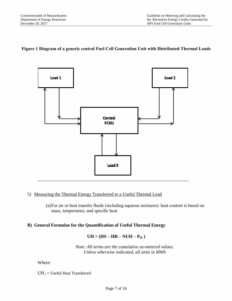
Figure 1 Diagram of a generic central Fuel Cell Generation Unit with Distributed Thermal Loads
5) Measuring the Thermal Energy Transferred to a Useful Thermal Load
(a) For air or heat transfer fluids (including aqueous mixtures): heat content is based on
mass, temperature, and specific heat
B) General Formulae for the Quantification of Useful Thermal Energy
UH = (HS – HR – NUH – Pth )
Note: All terms are the cumulative as-metered values.
Unless otherwise indicated, all units in MWh
Where:
UH t = Useful Heat Transferred
TAGGED

Commonwealth of Massachusetts Guideline on Metering and Calculating the
Department of Energy Resources the Alternative Energy Credits Generated by
December 29, 2017 APS Fuel Cell Generation Units
Page 8 of 16
HS = Heat Supplied by FCGU to Load
HR = Heat Returned from Load to FCGU
NUH = Non-useful heat
Pth = Parasitic thermal energy
C) General Formulae for the Quantification of Net Electricity Generated
Net Elec = (Eg – Ep - Es)
Note: All terms are the cumulative as-metered values.
Unless otherwise indicated, all units in MWh
Where :
Eg = Gross Electricity Generated
Ep = Parasitic Electricity
Es = Grid Electricity to FCGU auxiliary systems.
D) Minimum Efficiency Standard
Pursuant to 225 CMR 16.05(1)(a)7.b., all Fuel Cell Generation Units must meet an overall
efficiency standard. Fuel Cell Generation Units that generate electricity only must be more
efficient than the current average for emitting locational marginal units as based on the heat rates
for these units shown in the most recent ISO-NE Electric Generator Air Emissions Report
available in the same year in which a Fuel Cell Generation Unit submits an SQA.
Fuel Cell Generation Units that generated both electricity and Useful Thermal Energy must have
a net overall efficiency of 55% or higher. For the purpose of this standard, the definition of the
efficiency shall be:
Efficiency = ((net MWh Electricity) + (Useful Heat)) / (MWh equivalent of fuel consumed for
each month of the as-submitted
projected average year)
Approval of AECs as submitted to the NEPOOL Generation Information System (NEPOOL
GIS) for a given quarter shall be contingent upon achievement of the minimum metered average
efficiency, as defined in the definition of efficiency above. The MWh fuel consumed for the
given quarter is to be determined pursuant to the method and protocol described in Section 3 of
the APS Guideline on Biomass, Biogas, and Biofuels for APS Renewable Thermal Generation
Units.

Commonwealth of Massachusetts Guideline on Metering and Calculating the
Department of Energy Resources the Alternative Energy Credits Generated by
December 29, 2017 APS Fuel Cell Generation Units
Page 9 of 16
E) Acquisition, Recording, Storing, and Transmittal of Metered Data
All Fuel Cell Generation Units must include a Data Acquisition System (DAS) which must meet
the following minimum functional criteria:
(a) Input: Input must come from each APS metering system and component, at an interval
that does not to exceed 5 minute between inputs.
(b) Storage: 100 days of cumulative input data
(c) Output:
(i) Have remote electronic access to time stamped data of each input in five minute
intervals that can be exported as a comma separated values (.csv) file
(ii) Data is to be accessible by and transferred directly to the system Independent
Verifier and not via a third party.
The DAS may be a stand-alone dedicated unit or be integrated into an existing system.
F) Standards for APS Metering
All meters required by the APS must meet and conform to all applicable laws, ordinances, codes,
regulations, and standards, must be of revenue grade accuracy, quality, and reliability, and must
have the capability to generate and transmit a signal to the system DAS.
G) Thermal Energy Meters
Table 1. Thermal Energy Meter Requirements for Steam
Line
Size
Btu Meter System Components System
Field
Accuracy
Re-
Calibration
Interval
Notes
Flow Sensor and
Btu Computer
Temperature
& Pressure
Sensors
All
Btu Computer:
Automated real-
time computation
and totalizer
__ __ __ __

Commonwealth of Massachusetts Guideline on Metering and Calculating the
Department of Energy Resources the Alternative Energy Credits Generated by
December 29, 2017 APS Fuel Cell Generation Units
Page 10 of 16
≥8"
Flow Sensor:
Orifice Plate with
Differential
Pressure Element
and Transmitter
Only with
superheated
Steam
±3% Annual
1) Perform an annual inspection of the
flow sensor orifice plates and check for
wear and distortion beyond the OEMs
specifications as a part of the annual re-
calibration procedure
2) If a significant percentage of flow
occurs at flow rates below the flow
sensors minimum guaranteed full
accuracy flow rate, both the flow and Btus
may be undercounted. This can be
addressed by installing a two meter
manifold with the meters sized to cover
the entire expected range of flow rates.
Consult the flow meter provider for
design and installation details
< 8"
Flow Sensor:
Vortex Shedding
Tube
Only with
superheated
Steam
±3% Biennial __
Table 2. Thermal Energy Meter Requirements for Hot Water
Btu Meter System Components Btu Meter
Field Accuracy
Re- Calibration
Interval Notes
Flow Sensor:
In-line Ultrasonic Flow Tube (no strap-on)
or Magmeter
Thermal Sensors: Installed in thermowells
Btu Computer: Automated real-time
computation and totalizer
±3% Biennial
No turbine or
impellor based flow
sensors
Table 3. Thermal Energy Meter Requirements for Air
Btu Meter System Components Btu Meter
Field Accuracy
Re-
Calibration
Interval
Notes
Flow Sensor:
a) In-duct Differential Pressure Measuring
Airflow Station
b) Pitot Tube
Thermal Sensors: Installed in the air flow
stream
Btu Computer: Automated real-time
computation and totalizer
±3% Annual
Clean and inspect
orifices as a part of
the annual calibration
procedure
Commonwealth of Massachusetts Guideline on Metering and Calculating the
Department of Energy Resources the Alternative Energy Credits Generated by
December 29, 2017 APS Fuel Cell Generation Units
Page 11 of 16
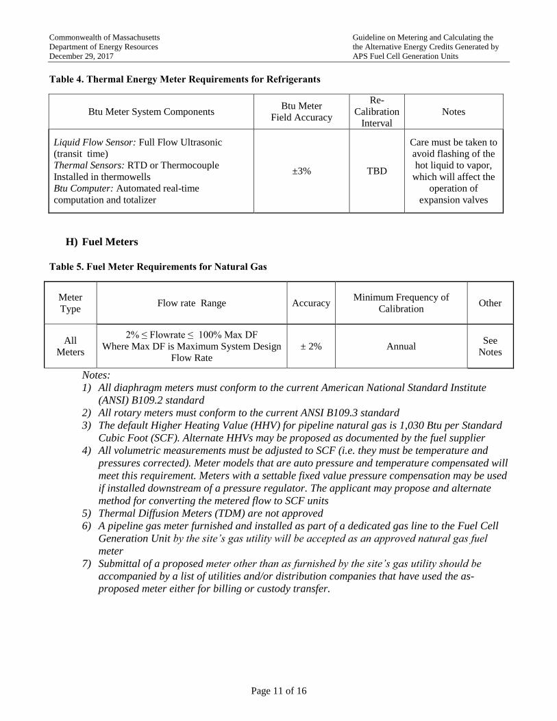
Table 4. Thermal Energy Meter Requirements for Refrigerants
Btu Meter System Components Btu Meter
Field Accuracy
Re-
Calibration
Interval
Notes
Liquid Flow Sensor: Full Flow Ultrasonic
(transit time)
Thermal Sensors: RTD or Thermocouple
Installed in thermowells
Btu Computer: Automated real-time
computation and totalizer
±3% TBD
Care must be taken to
avoid flashing of the
hot liquid to vapor,
which will affect the
operation of
expansion valves
H) Fuel Meters
Table 5. Fuel Meter Requirements for Natural Gas
Meter
Type
Flow rate Range
Accuracy Minimum Frequency of
Calibration Other
All
Meters
2% ≤ Flowrate ≤ 100% Max DF
Where Max DF is Maximum System Design
Flow Rate
± 2% Annual See
Notes
Notes:
1) All diaphragm meters must conform to the current American National Standard Institute
(ANSI) B109.2 standard
2) All rotary meters must conform to the current ANSI B109.3 standard
3) The default Higher Heating Value (HHV) for pipeline natural gas is 1,030 Btu per Standard
Cubic Foot (SCF). Alternate HHVs may be proposed as documented by the fuel supplier
4) All volumetric measurements must be adjusted to SCF (i.e. they must be temperature and
pressures corrected). Meter models that are auto pressure and temperature compensated will
meet this requirement. Meters with a settable fixed value pressure compensation may be used
if installed downstream of a pressure regulator. The applicant may propose and alternate
method for converting the metered flow to SCF units
5) Thermal Diffusion Meters (TDM) are not approved
6) A pipeline gas meter furnished and installed as part of a dedicated gas line to the Fuel Cell
Generation Unit by the site’s gas utility will be accepted as an approved natural gas fuel
meter
7) Submittal of a proposed meter other than as furnished by the site’s gas utility should be
accompanied by a list of utilities and/or distribution companies that have used the as-
proposed meter either for billing or custody transfer.

Commonwealth of Massachusetts Guideline on Metering and Calculating the
Department of Energy Resources the Alternative Energy Credits Generated by
December 29, 2017 APS Fuel Cell Generation Units
Page 12 of 16
Table 6. Fuel Meter Requirements for Biogas
Btu Meter System Components Btu Meter
Field Accuracy
Recalibration &
Inspection
Frequency
Notes
Gas Flow Sensor: Full Flow Averaging Pitot
Real time gas analyzer
Btu Computer: Automated real-time
computation and totalizer.
±3% Annual
Both tuned laser or
infrared based
optical gas
analyzer
technologies are
acceptable
I) Electric Meters
Electric (kWh) meters shall be revenue grade and shall:
1) Be certified as meeting American National Standard Institute (ANSI) Standard C12.20
2) Have a kW and kWh remote output signal with an output signal interval of not more
than once per minute
3) Have either a non-adjustable or password protected cumulative kWh register
J) Accuracy of Thermal and Fuel Metering
Thermal energy and fuel must be metered per the tables in 3(E) and 3(F) above, with a possible
future modification per the issuance of the American Society for Testing and Materials (ASTM)
Heat Meter Technology Standard WK37952 that is currently under development under the
leadership of the United States Environmental Protection Agency (EPA).
K) Use of non-Eligible Fuels when Combined with Eligible fuels
Possible Fuel Usage Modes
(a) Use of a single eligible fuel
(b) Co-firing of more than one eligible fuel
(c) Co-firing of one or more eligible fuels and one or more non-eligible fuel
(d) Blending of one or more eligible fuels
(e) Blending of one or more eligible fuels with one or more non-eligible fuels
Note: Co-firing denotes switching fuels without blending.
L) Components and Metering Diagrams
1) Components of a Fuel Cell Generation Unit that Generates Electricity and Useful Thermal
Energy via a Heat Transfer Fluid
The major components of a Fuel Cell Generation Unit include:

Commonwealth of Massachusetts Guideline on Metering and Calculating the
Department of Energy Resources the Alternative Energy Credits Generated by
December 29, 2017 APS Fuel Cell Generation Units
Page 13 of 16
(a) Fuel cell section
(b) Fuel reformer
(c) Fuel storage and delivery system
(d) Heat recovery and transfer system
(e) Over temperature protection system
(f) Controls
(g) Data acquisition system (DAS)
2) Metering for Large, Fired Fuel Cell Generation Units which Generate a Hot Heat Transfer
Fluid
The following guidelines are based on a generic basic configuration as shown in Figure 2.
The Department will evaluate metering plans and submittals based on alternative
configurations on a case-by-case basis.
Figure 2. Metering Diagram for an Fuel Cell Generation Unit that Generates Electricity and
Useful Thermal Energy via a Heat Transfer Fluid
``
Fuel Cell
RTGU HTF to Facility HTF
Heat Exchanger (s)
Facility Thermal
Loads ( Includes Absorption
Chillers)
Excess Heat Rejection System
Pump (s )
AuxiliarySystems,
Includes Excess
Heat Rejection System & Reformer
kWh Meter(s ) for any
kWh Supplied by Grid
* Btu Meter Hot
ThermalSensor
*
Btu Meter Cold
Thermal Sensor
*
Btu Meter Flow Meter
*
Ineligible Fuel Meter (i f needed)
*El igible or Blended
Fuel Meter (i f blending with
ineligibel fuel )
*
Data Acquisition System (DAS) with
remote communication and
time stamped I/O
Btu MeterComputer
*
An asteriks (*) indicates an input to the DAS
FCGU Output
kWh Meter(s)
*

Commonwealth of Massachusetts Guideline on Metering and Calculating the
Department of Energy Resources the Alternative Energy Credits Generated by
December 29, 2017 APS Fuel Cell Generation Units
Page 14 of 16
a) Formulae for APS AECs Generated and Efficiency over an Operating Interval
(all Energy is As-Metered and all Energy Units are MWH)
Notation
Eg = Gross Metered Electricity Generated
Ep = Metered Consumption of FCGU Electricity by Parasitic Loads
Es = Metered Consumption of Grid Supplied Electricity by Auxilliary Systems
Fe = Eligible Fuel
Fbe = A blend of two or more Eligible Fuels
Fi = Ineligible Fuel
Fbei = A blend of Eligible and Ineligible Fuels
UH = Useful Heat ( Heat Transferred to a Useful Load)
M = the Attribute Multiplier = 1.5
(i) FCGU when Using Only a Single Eligible Fuel
AECs = (Eg- Ep1 – Es) M
Efficiency = (Eg- Ep1 – Es + UH) / Fe
(ii) FCGU when Using a Blend of or Co-Firing only with Two Eligible Fuels
AECs = (Eg- Ep1 – Es) M
Efficiency = (Eg- Ep1 – Es + UH) /( Fe1 + Fe2)
(iii) FCGU when Co-Firing Using an Eligible and Ineligible Fuel
AECs = (Eg- Ep1 – Es) M only for intervals when an eligible fuel is being used
Efficiency = (Eg- Ep1 – Es) UH /( Fe + Fi) – Overt the entire interval including time when an
ineligible fuel is being used.
(iv) FCGU when Using a Blend of an Eligible with an Ineligible Fuel
AECs = (Fe/(Fbei) (Eg- Ep1 – Es) M
Efficiency = (Eg- Ep1 – Es + UH) / ( Fbei)

Commonwealth of Massachusetts Guideline on Metering and Calculating the
Department of Energy Resources the Alternative Energy Credits Generated by
December 29, 2017 APS Fuel Cell Generation Units
Page 15 of 16
Note(1) Figure 2 assumes a preferred configuration in which the connection of the Fuel Cell Generation
Unit electrical output to all parasitic loads occurs at a point before the main system APS Electrical Meter.
In this case Ep = 0. If this is not the case then the nominal parasitic loads must be identified and a method
for quantifying Ep over the interval must be submitted to the DOER for review and approval on a case by
case basis
Figure 3. Metering Diagram for a FCGU that Generates Electricity Only
b) Formulae for APS AECs Generated and Efficiency over an Operating Interval
(all Energy is As-Metered and all Energy Units are MWH)
Notation
Eg = Gross Metered Electricity Generated
Fuel Cell
AuxiliarySystems,
Includes Excess Heat Rejection
System & Reformer
kWh Meter(s ) for any kWh Supplied by
Grid
*
Ineligible Fuel Meter (i f needed)
*
El igible or Blended Fuel
Meter (i f blending with
ineligibel fuel )
*
Data Acquisition System (DAS) with
remote communication and
time stamped I/O
An asteriks (*) indicates an input to the DAS
FCGU
Output
kWh Meter(s)
*

Commonwealth of Massachusetts Guideline on Metering and Calculating the
Department of Energy Resources the Alternative Energy Credits Generated by
December 29, 2017 APS Fuel Cell Generation Units
Page 16 of 16
Ep = Metered Consumption of FCGU Electricity by Parasitic Loads
Es = Metered Consumption of Grid Supplied Electricity by Auxilliary Systems
Fe = Eligible Fuel
Fbe = A blend of two or more Eligible Fuels
Fi = Ineligible Fuel
Fbei = A blend of Eligible and Ineligible Fuels
(i) FCGU when Using Only a Single Eligible or
AECs = (Eg- Ep1 – Es) M
Efficiency = (Eg- Ep1 – Es) / Fe
(ii) FCGU when Using a Blend of or Co-Firing only with Two Eligible Fuels
AECs = (Eg- Ep1 – Es) M
Efficiency = (Eg- Ep1 – Es) /( Fe1 + Fe2)
(iii) FCGU when Co-Firing Using an Eligible and Ineligible Fuel
AECs = (Eg- Ep1 – Es) M only for intervals when an eligible fuel is being used
Efficiency = (Eg- Ep1 – Es) /( Fe + Fi)
(iv) FCGU when Using a Blend of an Eligible with an Ineligible Fuel
AECs = (Fe/( Fe + Fi)) (Eg- Ep1 – Es) M
Efficiency = (Eg- Ep1 – Es) /( Fe + Fi)
Note(1) Figures 2 and 3 assume a preferred configuration in which the connection of the Fuel Cell
Generation Unit electrical output to all parasitic loads occurs at a point before the main system APS
electrical meter. In this case Ep = 0. If this is not the case then the nominal parasitic loads must be
identified and a method for quantifying Ep over the interval must be submitted to the DOER for review and
approval on a case by case basis.