Embed Size (px)
Citation preview

— 1 ZSC0 0 0 5 6 2- ACU EN , R E V. A
On-load tap-changers, type UZ, with motor-drive mechanism, type BUF3Spare parts list
This spare parts list has been compiled to help you with procurement of spares. To obtain trouble-free deliveries you should note a few things which are explained in the following text.
The breakdown level and general contents of this list have been worked out to cover normal customer requests. Our spares sales people will be happy to assist if you require any specific item that is not included in the list.
Type designation and serial numberThe rating plate on the on-load tap-changer shows which type and serial number of the device you are ordering spares for. It is important to have this information, because the manufacture of parts gradually changes as materials and manufacturing technology improves. ABB makes every effort to supply spares that should fit your requirements. Some parts of later manufacture than those you are replacing may need some adaptation to fit into your device. Our spare parts sales people need to know the type designation and serial number to supply exactly what you require.
Item numberItem numbers are shown on the drawings and lists. As you will observe, one item number is used for several items of the same general type. These items have a specific specification for each and every variant of on-load tap-changer, hence you need to specify type and serial number in addition to the item number to obtain the appropriate spare.
Name of itemThe name should be specified when ordering to make sure the right type of item is ordered.
QuantityThe figures given represent the number of items included in one on-load tap-changer.
RemarksInformation pertinent to different variants of the on-load tap-changer is given in this column. Your model should be one of those shown.
Standard spare partsThe rugged design of ABB on-load tap-changers means that only the fixed and moving contacts of the selector switch might require replacement during the lifetime of the transformer. This spare parts list tells you the part number of the contacts when ordering for your replacement requirements.
Special spare partsIf you need parts other than the contacts in the lists, our staff will be happy to assist you. Please use the illustrations is this list as a reference when discussing your requirements. As usual, the type designation and serial number are essential for ordering.

2 O N - LOA D TA P - CH A N G E R S T Y PE UZ SPA R E PA RTS L IS T
Three-phase assembly
Item No. Name of item Quantity per tap-changer phase Remarks
103 Transition resistor 3 1
118 Geneva gear 1 See pages 14, 15
130a,b,c Selector-switch phase See pages 12, 13
132a Retaining plate 10 UZE.. 200/..., UZF.. 200/...
132b Retaining plate 4 UZE.. 200/..., UZF.. 200/...
132c Retaining plate 10 UZE.. 250/..., UZF.. 250/...
132d Retaining plate 4 UZE.. 250/..., UZF.. 250/...
132c Retaining plate 18 UZE.. 380, 550, 650/...,UZF.. 380, 550, 650/...
133 Steel board 1 UZE.. 200/..., UZF.. 200/...
133 Bakelite board 1 UZE.. 380/..., UZF.. 380/...
133 Bakelite board 1 UZE.. 550/..., UZF.. 550/...
133 Bakelite board 1 UZE.. 650/..., UZF.. 650/...
136 Insulating shaft 200, 250 kV 4 (1) UZER,DN, UZER,DN 1) (UZELN, UZFLN)
136 Insulating shaft 200, 250 kV 6 (3) UZERT, UZFRT (UZELT, UZFLT) 1)
136 Insulating shaft 380 kV 4 (1) UZERN, UZFRN (UZELN, UZFLN) 1)
136 Insulating shaft 380 kV 6 (3) UZERT, UZFRT (UZELT, UZFLT) 1)
136 Insulating shaft 550, 650 kV 4 (1) UZERN, UZFRN (UZELN, UZFLN) 1)
136 Insulating shaft 550, 650 kV 6 (3) UZERT, UZFRT (UZELT, UZFLT) 1)
137 Steel shaft 2 UZE.N 200, 250/..., UZF.N 200, 250/...
137 Steel shaft 2 UZE.N 380/..., UZF.N 380/...
137 Steel shaft 2 UZE.N 550, 650/..., UZF.N 550, 650/...
140 Coupling 6 (3) UZER,D, UZFR,D (UZEL, UZFL) 1)
Another design was introduced in February 1987. When ordering, please contact ABB
152-154 Set of nuts + washers 42 UZE.. 200, 250/..., UZF.. 200, 250/...
152-154 Set of nuts + washers 56 UZE.. 380/..., UZF.. 380/...
152-154 Set of nuts + washers 66 UZE.. 550, 650/..., UZF.. 550, 650/...
155-157 Set of nuts + washers + screws 42 UZE.. 200/..., UZF.. 200/...
155 Nut 42 UZE.. 250/..., UZF.. 250/...
155 Nut 54 UZE.. 380, 550, 650/...,UZF.. 380, 550, 650/...
160 Set of:3+6 allen screws6+12 locking washers3 brackets
2 (1) UZER,D, UZFR,D (UZEL, UZFL) 1)
185 Shield When ordering, please contact ABB
1) Pos 136, 140, 160: Quantity ( ) See Remarks ( ).

O N - LOA D TA P - CH A N G E R S T Y PE UZ SPA R E PA RTS L IS T 3

4 O N - LOA D TA P - CH A N G E R S T Y PE UZ SPA R E PA RTS L IS T
Selector-switch phase
Item No. Name of item Quantity per tap-changer phase Remarks
101 Body 3 1 See pages 16, 17
109a Shaft for main contact 2
109b Shaft for main contact 1
111 Set of change-over selector, including the fixed contacts
3 1 UZER,D, UZEYD, .../...2) 4)
UZFR, D, UZFYD, .../... 2)
A complete type designation has to be stated.
117a Shaft, change-over 2 (1) UZER, UZFR (UZED, UZFD) 1) 4)
117b Shaft, change-over 1 UZER, UZFD 4)
117c Shaft, change-over 1 UZED, UZFD 4)
117d Shaft, change-over 1 UZED, UZFD 4)
127 Current collector 3 (6) 1(2) 150, 300A (500, 600 A) 1)
130a+c Selector switch phase 5-11 pos 2+1 1 UZEL.../150, UZFL.../150 2)
130a+c 12-17 pos 2+1 1 UZEL.../150, UZFL.../150 2)
130a+c 5-11 pos 2+1 1 UZEL.../300-600, UZFL.../300-600 2)
130a+c 12-17 pos 2+1 1 UZEL.../300-600, UZFL.../300-600
130a+c 7-23 pos 2+1 1 UZER.../150, UZFR.../150 2)
130a+c 25-33 pos 2+1 1 UZER.../150, UZFR.../150 2)
130a+c 7-23 pos 2+1 1 UZER.../300-600, UZFR.../300-600 2)
130a+c 25-33 pos 2+1 1 UZER.../300-600, UZFR.../300-600 2)
130a+b+c 7-23 pos 1+1+1 1 UZED.../150, UZFD.../150 2)
130a+b+c 25-29 pos 1+1+1 1 UZED.../150, UZFD.../150 2)
130a+b+c 7-23 pos 1+1+1 1 UZED.../300-600, UZFD.../300-600 2)
130a+b+c 25-29 pos 1+1+1 1 UZED.../300-600, UZFD.../300-600 2)
130.1 Addition for shielding 3 1 UZEL. 550/..., UZFL. 550/... 3)
130.1 Addition for shielding 3 1 UZER,D 550/..., UZFR,D. 550/... 3)
135 Moving contact system See pages 18, 19, 20, 21
161 Taper-pin 3 1 UZEL, UZFL
161 Taper-pin 6 2 UZER,D, UZFR,D 4)
185 Shield When ordering, please contact ABB
1) Pos 117a, 127: Quantity ( ), See Remarks ( ). 2) Pos 111, 130: for UZE..550, 650/... and UZF..550, 650/... addition for shielding must be added.3) Pos 130.1: for UZE.T 550, 650/... and UZF.T 550, 650/... pos 135.1 (see pages 10-11) must be added.4) Pos 111, 117, 161: Delivered as integral assembly.

O N - LOA D TA P - CH A N G E R S T Y PE UZ SPA R E PA RTS L IS T 5

6 O N - LOA D TA P - CH A N G E R S T Y PE UZ SPA R E PA RTS L IS T
Item No. Name of item Quantity per tap-changer phase
Remarks
118 Complete set of geneva gear 1 UZEL, UZFL 5-11 pos 1)
118 Complete set of geneva gear 1 UZEL, UZFL 12-17 pos 1)
118 Complete set of geneva gear 1 UZER, UZFR 7-23 pos 1)
118 Complete set of geneva gear 1 UZER, UZFR 25-33 pos 1)
118 Complete set of geneva gear 1 UZED, UZFD 7-23 pos 1)
118 Complete set of geneva gear 1 UZED, UZFD 25-29 pos 1)
141 Geneva drive 1 UZEL .../.., UZFL .../... 5-11 pos
141 Geneva drive 1 UZER,D .../..., UZFR,D .../... 7-23 pos
141 Geneva drive 1 UZEYD .../..., UZFYD .../... 10-22 pos
141 Geneva drive 1 UZEL .../..., UZFL .../... 12-17 pos
141 Geneva drive 1 UZER .../..., UZFR .../... 25-33 pos
141 Geneva drive 1 UZED .../..., UZFD .../... 25-29 pos
141 Geneva drive 1 UZEYD .../..., UZFYD .../... 24-28 pos
142 Geneva wheel 1 UZEL, UZFL 5-11 pos 1)
142 Geneva wheel 1 UZEL, UZFL 12-17 pos 1)
142 Geneva wheel 1 UZER,D, UZFR,D 7-23 pos 1)
142 Geneva wheel 1 UZER,D, UZFR,D 25-33 pos 1)
142.1 Drilling for shield 1 UZEL. 550-650/..., UZFL. 550-650/...
143 Geneva arm 1 UZER,D, YD, UZFR,D, YD7-23 pos, 10-22 pos
143 Geneva arm 1 UZER,D, YD, UZFR,D, YD25-33 pos, 25-29 pos, 24-28 pos
144 Change-over arm 1 UZER 200-650/..., UZFR 200-650... 2)
144 Change-over arm 1 UZED 200-650/..., UZFD 200-650... 2)
162 Crank arm 1
163 Bearing 1
185 Shield When ordering, please contact ABB
1) Pos 118,142: for UZE.. 550 and UZF.. 550/... addition for shielding must be added. Pos 118: for UZER. 550/... and UZFR. 550/... pos 142.1 + 185 Pos 142: for UZEL. 550, 650/... and UZFL. 550, 650/... pos 142.1
2) Pos 144: for UZER,D. 550-650/... and UZFR,D. 550-650/... pos 185 must be added.
Geneva gear

O N - LOA D TA P - CH A N G E R S T Y PE UZ SPA R E PA RTS L IS T 7
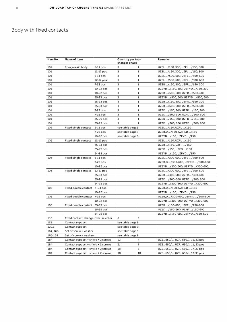
8 O N - LOA D TA P - CH A N G E R S T Y PE UZ SPA R E PA RTS L IS T
Item No. Name of item Quantity per tap-changer phase
Remarks
101 Epoxy-resin body 5-11 pos 3 1 UZEL .../150, 300, UZFL .../150, 300
101 12-17 pos 3 1 UZEL .../150, 300, UZFL .../150, 300
101 5-11 pos 3 1 UZEL .../500, 600, UZFL .../500, 600
101 12-17 pos 3 1 UZEL .../500, 600, UZFL .../500, 600
101 7-23 pos 3 1 UZER .../150, 300, UZFR .../150, 300
101 10-22 pos 3 1 UZEYD .../150, 300, UZFYD .../150, 300
101 10-22 pos 3 1 UZER .../500, 600, UZFR .../500, 600
101 25-33 pos 3 1 UZEYD .../500, 600, UZFYD .../500, 600
101 25-33 pos 3 1 UZER .../150, 300, UZFR .../150, 300
101 25-33 pos 3 1 UZER .../500, 600, UZFR .../500, 600
101 7-23 pos 3 1 UZED .../150, 300, UZFD .../150, 300
101 7-23 pos 3 1 UZED .../500, 600, UZFD .../500, 600
101 25-29 pos 3 1 UZED .../150, 300, UZFD .../150, 300
101 25-29 pos 3 1 UZED .../500, 600, UZFD .../500, 600
105 Fixed single contact 5-11 pos see table page 9 UZEL .../150, UZFL .../150
7-23 pos see table page 9 UZER,D .../150, UZFR,D .../150
10-22 pos see table page 9 UZEYD .../150, UZFYD .../150
105 Fixed single contact 12-17 pos UZEL .../150, UZFL .../150
25-33 pos UZER .../150, UZFR .../150
25-29 pos UZED .../150, UZFD .../150
24-28 pos UZEYD .../150, UZFYD .../150
105 Fixed single contact 5-11 pos UZEL .../300-600, UZFL .../300-600
7-23 pos UZER,D .../300-600, UZFR,D .../300-600
10-22 pos UZEYD .../300-600, UZFYD .../300-600,
105 Fixed single contact 12-17 pos UZEL .../300-600, UZFL .../300, 600
25-33 pos UZER .../300-600, UZFR .../300, 600
25-29 pos UZED .../300-600, UZFD .../300, 600
24-28 pos UZEYD .../300-600, UZFYD .../300-600
106 Fixed double contact 7 -23 pos UZER,D .../150, UZFR,D .../150
10-22 pos UZEYD .../150, UZFYD .../150
106 Fixed double contact 7-23 pos UZER,D .../300-600, UZFR,D .../300-600
10-22 pos UZEYD .../300-600, UZFYD .../300-600
106 Fixed double contact 25-33 pos UZER .../150-600, UZFR .../150-600
25-29 pos UZED .../150-600, UZFD .../150-600
24-28 pos UZEYD .../150-600, UZFYD .../150-600
116 Fixed contact, change-over selector 6 2
129 Contact support see table page 9
129.1 Contact support see table page 9
164, 168 Set of screw + washer see table page 9
166-168 Set of screw + washers see table page 9
184 Contact support + shield + 2 screws 12 4 UZE.. 550/..., UZF.. 550/... 11, 23 pos
184 Contact support + shield + 2 screws 21 7 UZE.. 650/..., UZF.. 650/... 11, 23 pos
184 Contact support + shield + 2 screws 18 6 UZE.. 550/..., UZF.. 550/... 17, 33 pos
184 Contact support + shield + 2 screws 30 10 UZE.. 650/..., UZF.. 650/... 17, 33 pos
Body with fixed contacts
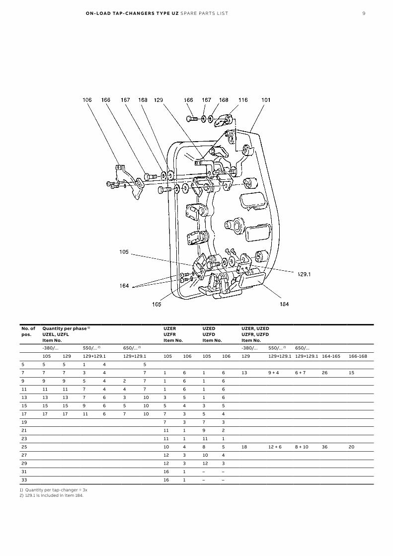
O N - LOA D TA P - CH A N G E R S T Y PE UZ SPA R E PA RTS L IS T 9
No. of pos.
Quantity per phase 1)
UZEL, UZFL Item No.
UZERUZFRItem No.
UZEDUZFDItem No.
UZER, UZEDUZFR, UZFDItem No.
-380/... 550/... 2) 650/... 2) -380/... 550/... 2) 650/...
105 129 129+129.1 129+129.1 105 106 105 106 129 129+129.1 129+129.1 164-165 166-168
5 5 5 1 4 5
7 7 7 3 4 7 1 6 1 6 13 9 + 4 6 + 7 26 15
9 9 9 5 4 2 7 1 6 1 6
11 11 11 7 4 4 7 1 6 1 6
13 13 13 7 6 3 10 3 5 1 6
15 15 15 9 6 5 10 5 4 3 5
17 17 17 11 6 7 10 7 3 5 4
19 7 3 7 3
21 11 1 9 2
23 11 1 11 1
25 10 4 8 5 18 12 + 6 8 + 10 36 20
27 12 3 10 4
29 12 3 12 3
31 16 1 – –
33 16 1 – –
1) Quantity per tap-changer = 3x 2) 129.1 is included in item 184.

10 O N - LOA D TA P - CH A N G E R S T Y PE UZ SPA R E PA RTS L IS T
Item No. Name of item Quantity per tap-changer phase
Remarks
107 Arm 3 1
114 Moving main and sw. contact 3 1 UZE .../150, UZF ../150
114 Moving main and sw. contact 3 1 UZE .../300, UZF ../300
114 Moving main and sw. contact 3 1 UZE .../500, UZF ../500
114 Moving main and sw. contact 3 1 UZE .../600, UZF.../600
115 Moving transition contact 3 1 UZEL .../150, UZFL .../150; 5-11 posUZER,D .../150, UZFR,D .../150; 7-23 posUZEYD .../150, UZFYD .../150; 10-22 pos
115 Moving transition contact 3 1 UZEL .../300-600, UZFL .../300-600; 5-11 posUZER,D .../300-600, UZFR,D .../300-600; 7-23 posUZEYD .../300-600, UZFYD .../300-600; 10-22 pos
115 Moving transition contact 3 1 UZEL .../150, UZFL .../150; 12-17 posUZER .../150, UZFR .../150; 25-33 posUZED .../150, UZFD.../150; 25-29 posUZEYD .../150, UZFY .../150; 24-28 pos
115 Moving transition contact 3 1 UZEL .../300-600, UZFL .../300-600; 12-17 posUZER .../300-600, UZFR .../300-600; 25-33 posUZED .../300-600, UZFD .../300-600; 25-29 posUZEYD .../300-600,UZFYD .../300-600; 24-28 pos
135 Moving contact system 3 1 UZEL .../150, UZFL .../150; 5-11 pos 1)
UZER,D .../150, UZFR,D .../150; 7-23 pos 1)
UZEYD .../150, UZFYD .../150; 10-22 pos 1)
135 Moving contact system 3 1 UZEL .../300, UZFL .../300; 5-11 pos 1)
UZER,D .../300, UZFR,D .../300; 7-23 pos 1)
UZEYD .../300, UZFYD .../300; 10-22 pos 1)
135 Moving contact system 3 1 UZEL .../500, UZFL .../500; 5-11 pos 1)
UZER,D .../500, UZFR,D .../500; 7-23 pos 1)
UZEYD .../500, UZFYD .../500; 10-22 pos 1)
135 Moving contact system 3 1 UZEL .../600, UZFL .../600; 5-11 pos 1)
UZER,D .../600, UZFR,D .../600; 7-23 pos 1)
UZEYD .../600, UZFYD .../600; 10-22 pos 1)
1) Item 135; for UZE.T 550-650/..., UZF.T 550-650/... pos 135.1 must be added.
Moving contact details

O N - LOA D TA P - CH A N G E R S T Y PE UZ SPA R E PA RTS L IS T 11

12 O N - LOA D TA P - CH A N G E R S T Y PE UZ SPA R E PA RTS L IS T
Item Name of item Quantity per tap-changer phase
Remarks
135 Moving contact system 3 1 UZEL .../150, UZFL .../150; 12-17 pos 1)
UZER .../150, UZFR .../150; 25-33 pos 1)
UZED .../150, UZFD .../150; 25-29 pos 1)
UZEYD .../150, UZFYD .../150; 24-28 pos 1)
135 Moving contact system 3 1 UZEL .../300, UZFL .../300; 12-17 pos 1)
UZER .../300, UZFR .../300; 25-33 pos 1)
UZED .../300, UZFD .../300; 25-29 pos 1)
UZEYD .../300, UZFYD .../300; 24-28 pos 1)
135 Moving contact system 3 1 UZEL .../500, UZFL .../500; 12-17 pos 1)
UZER .../500, UZFR .../500; 25-33 pos 1)
UZED .../500, UZFD .../500; 25-29 pos 1)
UZEYD .../500, UZFYD .../500; 24-28 pos 1)
135 Moving contact system 3 1 UZEL .../600, UZFL .../600; 12-17 pos 1)
UZER .../600, UZFR .../600; 25-33 pos 1)
UZED .../600, UZFD .../600; 25-29 pos 1)
UZEYD .../600, UZFYD .../600; 24-28 pos 1)
135.1 Bracket for shield 3 1 UZE.T 550-650, UZF.T 550-650
169-171 Set of screw + washers 6 2
172 Bracket 3 1
173-175 Set of screw + washer + nut 6 2
176-179 Set of screw + washer + roll pin 6 2
180 Insulation board 6 2
181-183 Set of screw + washer + nut 6 2
1) Item 135: for UZE.T 550-650/..., UZF.T 550-650/... pos 135.1 must be added

O N - LOA D TA P - CH A N G E R S T Y PE UZ SPA R E PA RTS L IS T 13
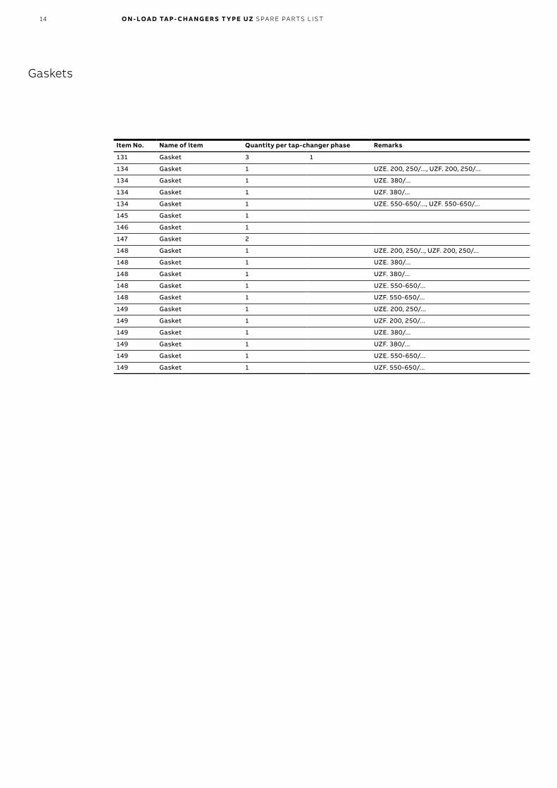
14 O N - LOA D TA P - CH A N G E R S T Y PE UZ SPA R E PA RTS L IS T
Item No. Name of item Quantity per tap-changer phase Remarks
131 Gasket 3 1
134 Gasket 1 UZE. 200, 250/..., UZF. 200, 250/...
134 Gasket 1 UZE. 380/...
134 Gasket 1 UZF. 380/...
134 Gasket 1 UZE. 550-650/..., UZF. 550-650/...
145 Gasket 1
146 Gasket 1
147 Gasket 2
148 Gasket 1 UZE. 200, 250/.., UZF. 200, 250/...
148 Gasket 1 UZE. 380/...
148 Gasket 1 UZF. 380/...
148 Gasket 1 UZE. 550-650/...
148 Gasket 1 UZF. 550-650/...
149 Gasket 1 UZE. 200, 250/...
149 Gasket 1 UZF. 200, 250/...
149 Gasket 1 UZE. 380/...
149 Gasket 1 UZF. 380/...
149 Gasket 1 UZE. 550-650/...
149 Gasket 1 UZF. 550-650/...
Gaskets

O N - LOA D TA P - CH A N G E R S T Y PE UZ SPA R E PA RTS L IS T 15
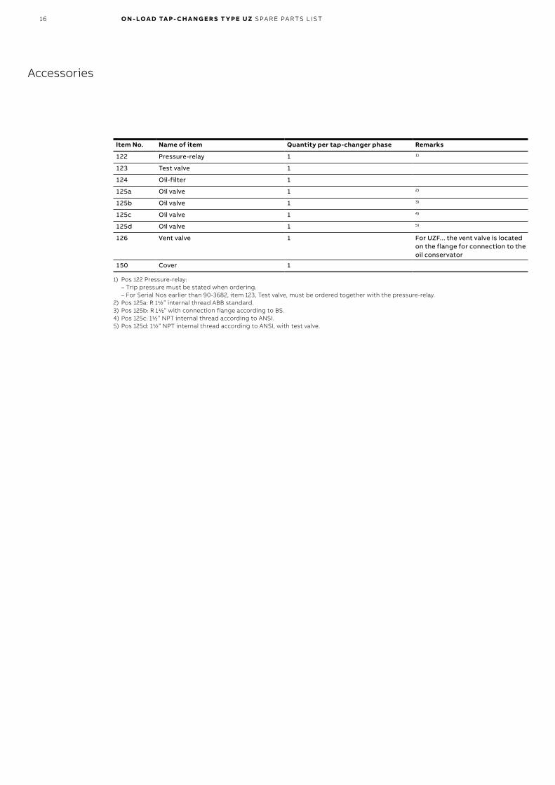
16 O N - LOA D TA P - CH A N G E R S T Y PE UZ SPA R E PA RTS L IS T
Item No. Name of item Quantity per tap-changer phase Remarks
122 Pressure-relay 1 1)
123 Test valve 1
124 Oil-filter 1
125a Oil valve 1 2)
125b Oil valve 1 3)
125c Oil valve 1 4)
125d Oil valve 1 5)
126 Vent valve 1 For UZF... the vent valve is located on the flange for connection to the oil conservator
150 Cover 1
1) Pos 122 Pressure-relay: – Trip pressure must be stated when ordering. – For Serial Nos earlier than 90-3682, item 123, Test valve, must be ordered together with the pressure-relay.
2) Pos 125a: R 1½” internal thread ABB standard.3) Pos 125b: R 1½” with connection flange according to BS.4) Pos 125c: 1½” NPT internal thread according to ANSI.5) Pos 125d: 1½” NPT internal thread according to ANSI, with test valve.
Accessories

O N - LOA D TA P - CH A N G E R S T Y PE UZ SPA R E PA RTS L IS T 17

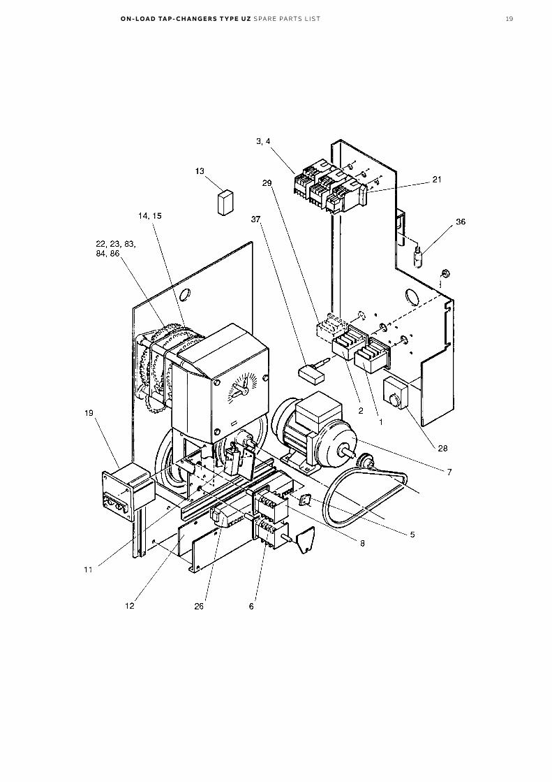
18 O N - LOA D TA P - CH A N G E R S T Y PE UZ SPA R E PA RTS L IS T
Item No. Name of item Quantity Remarks
1 Control selector-switch 1
2 Control switch raise/lower 1
3 Motor contactor 1 Raise
4 Motor contactor 1 Lower
5 Starting contact 1
6 Maintaining interlocking and auxiliary contact 1
7 Motor 1
8 Limit switch 1
11 Interlocking switch 1
12 Heater 50 W 1
13 Measuring amplifier (option) 1 13-35 pos
14 Position transmitter 1
15 Continuation contact 1
19 Motor protective switch 1
21 Step by step-contactor 1
22 Auxiliary contact, break before make 1
23 Auxiliary contact, make before break 1
26 Terminal blocks 1
27 Heater 250 W (option) 1
28 Thermostat (option) 1
29 Control switch for heater 1
36 Cabinet light 1
37 Switch, door operated (option) 1
83 Master switch (option) 1
84 Follower switch (option) 1
86 Step switch 1
Motor-drive mechanism, mechanical and electrical details
O N - LOA D TA P - CH A N G E R S T Y PE UZ SPA R E PA RTS L IS T 19
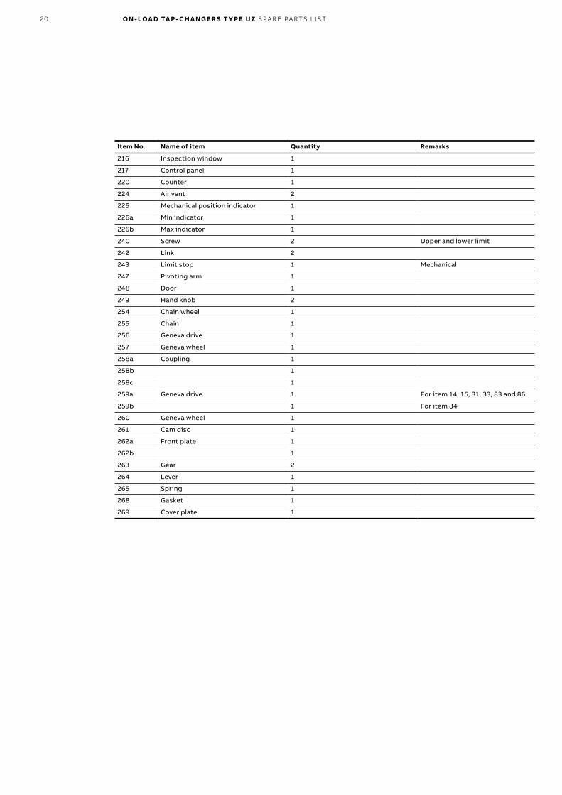
20 O N - LOA D TA P - CH A N G E R S T Y PE UZ SPA R E PA RTS L IS T
Item No. Name of item Quantity Remarks
216 Inspection window 1
217 Control panel 1
220 Counter 1
224 Air vent 2
225 Mechanical position indicator 1
226a Min indicator 1
226b Max indicator 1
240 Screw 2 Upper and lower limit
242 Link 2
243 Limit stop 1 Mechanical
247 Pivoting arm 1
248 Door 1
249 Hand knob 2
254 Chain wheel 1
255 Chain 1
256 Geneva drive 1
257 Geneva wheel 1
258a Coupling 1
258b 1
258c 1
259a Geneva drive 1 For item 14, 15, 31, 33, 83 and 86
259b 1 For item 84
260 Geneva wheel 1
261 Cam disc 1
262a Front plate 1
262b 1
263 Gear 2
264 Lever 1
265 Spring 1
268 Gasket 1
269 Cover plate 1

O N - LOA D TA P - CH A N G E R S T Y PE UZ SPA R E PA RTS L IS T 21


—ABB AB, ComponentsSE-771 80 LudvikaSwedenE-mail: [email protected]
www.abb.com/transformercomponents
1ZS
C0
00
56
2-A
CU
en
, Rev
. A, 2
018
-11-
15
© Copyright 2018 ABB. All rights reserved. Specifications subject to change without notice.