Embed Size (px)
Citation preview
OnOn--Line Partial Line Partial Discharge TestingDischarge Testing
Skip HicksDirector - New Business Development
What Is Partial Discharge?What Is Partial Discharge?What Is Partial Discharge?According the the International Electrotechnical Commission (IEC) International Standard 60270, Section 3.1 published in 2000, the definition of Partial Discharge is:
“Localized electrical discharge that only partially bridges the insulation between conductors and which can or cannot occur adjacent to a conductor.”
IEC 60270 Section 3.1 NotesIEC 60270 Section 3.1 NotesIEC 60270 Section 3.1 Notes“Partial discharges are in general a consequence of local electrical stress concentrations in the insulation or on the surface of the insulation…”
“Corona is a form of partial discharge that occurs in gaseous media around conductors which are remote from solid or liquid insulation…”
“Partial discharges are often accompanied by emission of sound, light, heat, and chemical reactions…”
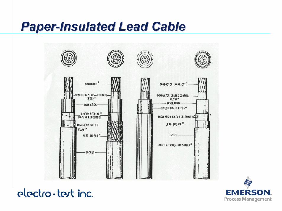
Paper-Insulated Lead CablePaperPaper--Insulated Lead CableInsulated Lead Cable
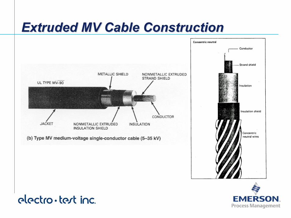
Extruded MV Cable ConstructionExtruded MV Cable ConstructionExtruded MV Cable Construction
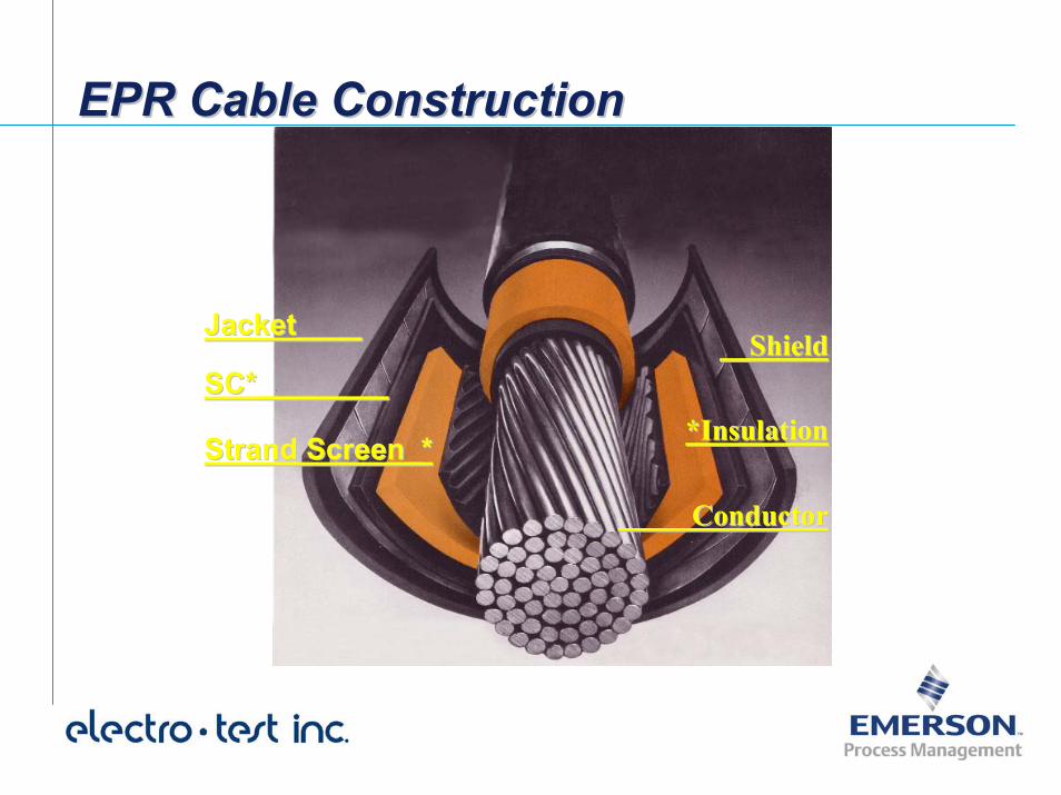
EPR Cable ConstructionEPR Cable ConstructionEPR Cable Construction
Jacket____Jacket____
SC*________SC*________
Strand Screen_*Strand Screen_*
__Shield__Shield
*Insulation*Insulation
ConductorConductor
EPR Insulation in Cable AccessoriesEPR Insulation in Cable AccessoriesEPR Insulation in Cable Accessories
Most Pre-Molded Cable Terminations, Stress Cones and other Cable Accessories are manufactured from an EPR compound because of it’s great resistance to treeing and the effects of corona discharge around terminations and splices.
Types of Cable FailuresTypes of Cable FailuresTypes of Cable Failures
Laminar Insulation Failures
Voltage Stress Related Failures in Extruded Insulation
Cable Accessory Failure
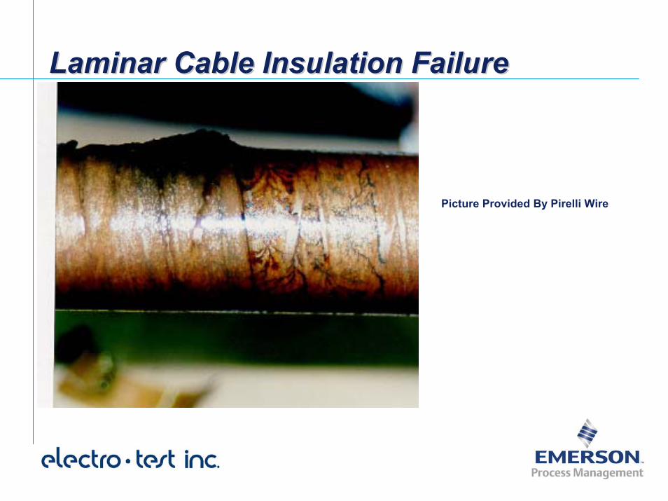
Laminar Cable Insulation FailureLaminar Cable Insulation FailureLaminar Cable Insulation Failure
Picture Provided By Pirelli Wire
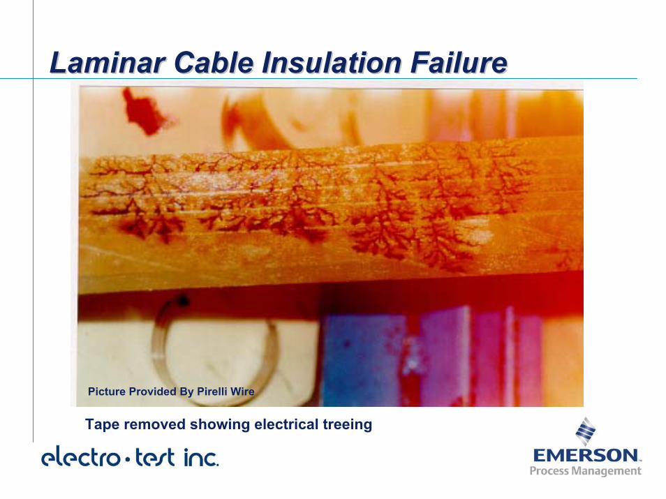
Laminar Cable Insulation FailureLaminar Cable Insulation FailureLaminar Cable Insulation Failure
Picture Provided By Pirelli Wire
Tape removed showing electrical treeing
Voltage Stress Related Failures in Extruded InsulationVoltage Stress Related Failures in Voltage Stress Related Failures in Extruded InsulationExtruded Insulation
Overloads, defects or weak spots in insulation lead to chemical breakdown of the insulation, producing thermal runaway leading to decreased Insulation Resistance, increased leakage current and failure.
Design, manufacturing or workmanship results in voids or contamination which produce Partial Discharge and ultimate failure.
Water Trees Form and convert to Electrical Trees and lead to ultimate failure.
Voltage Stress Related Failures in Extruded InsulationVoltage Stress Related Failures in Voltage Stress Related Failures in Extruded InsulationExtruded Insulation [2]
Water migration into the insulation leads to water trees. Water Trees lead to decreased insulation resistance and very slight increase in leakage current. Water Trees do not directly produce failure.
Water Trees lead to electrical trees which produce Partial Discharge and ultimate failure.
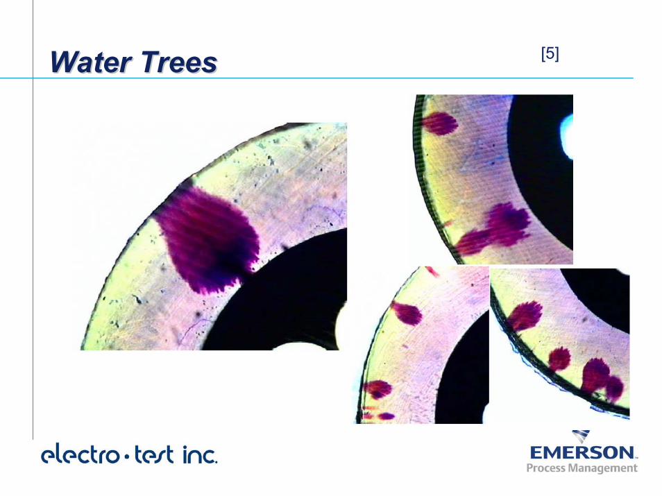
[5]Water TreesWater TreesWater Trees
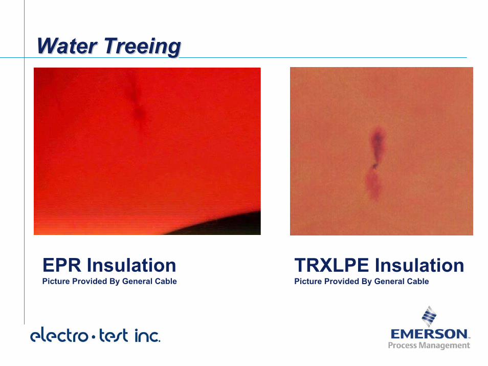
Water TreeingWater TreeingWater Treeing
EPR InsulationPicture Provided By General Cable
TRXLPE InsulationPicture Provided By General Cable
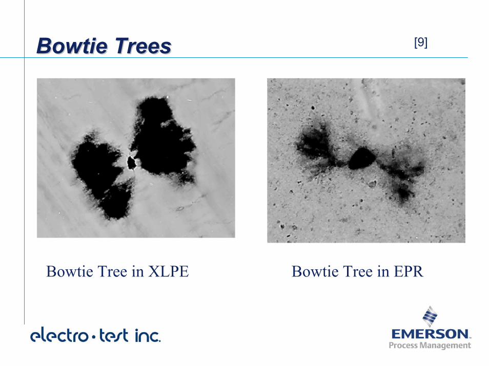
Bowtie TreesBowtie TreesBowtie Trees [9]
Bowtie Tree in XLPE Bowtie Tree in EPR
Water Tree ConversionWater Tree ConversionWater Tree Conversion [2]
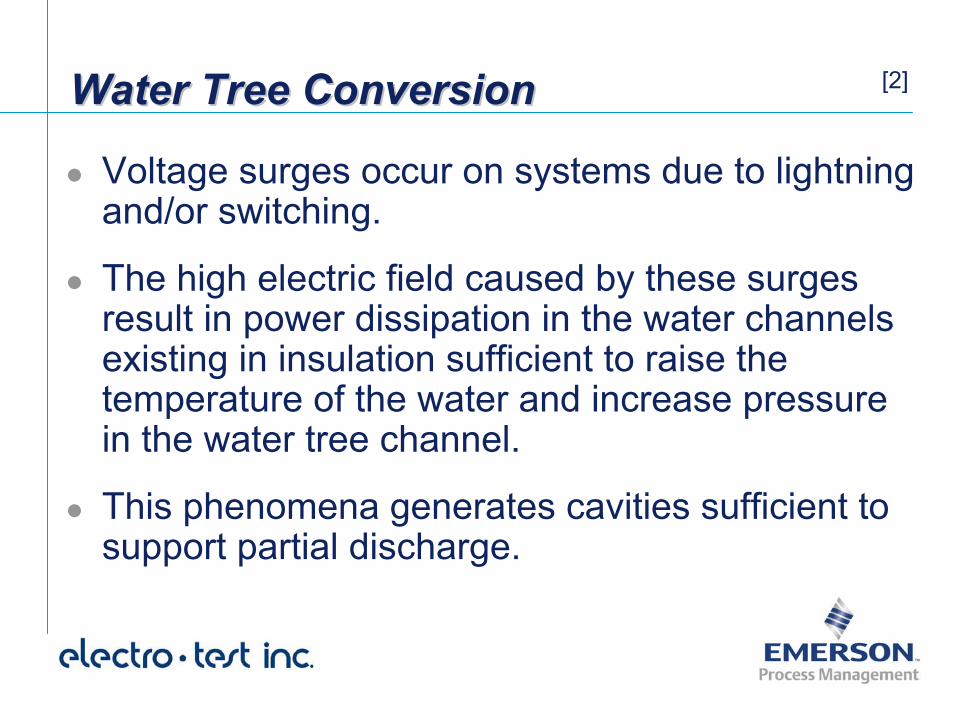
Voltage surges occur on systems due to lightning and/or switching.
The high electric field caused by these surges result in power dissipation in the water channels existing in insulation sufficient to raise the temperature of the water and increase pressure in the water tree channel.
This phenomena generates cavities sufficient to support partial discharge.
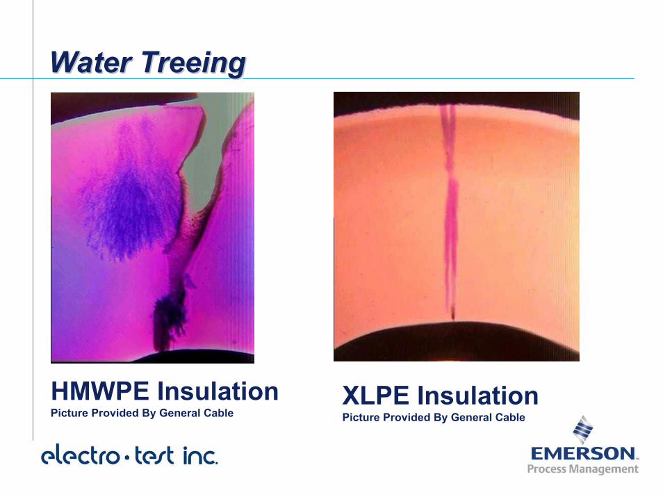
Water TreeingWater TreeingWater Treeing
HMWPE InsulationPicture Provided By General Cable
XLPE InsulationPicture Provided By General Cable
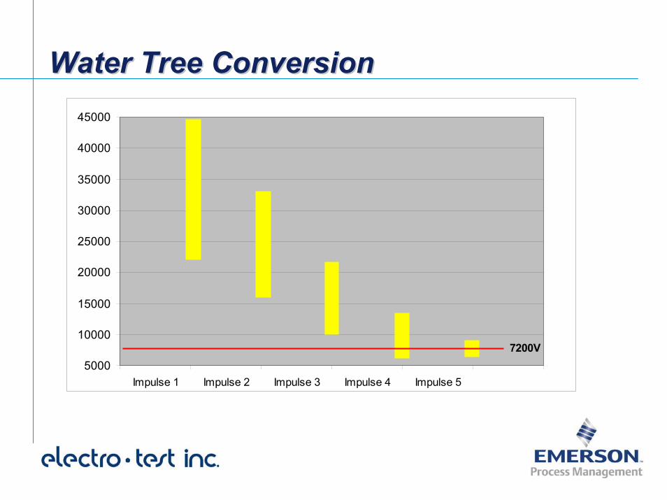
Water Tree ConversionWater Tree ConversionWater Tree Conversion
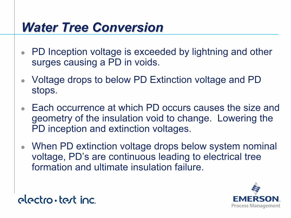
PD Inception voltage is exceeded by lightning and other surges causing a PD in voids.
Voltage drops to below PD Extinction voltage and PD stops.
Each occurrence at which PD occurs causes the size and geometry of the insulation void to change. Lowering the PD inception and extinction voltages.
When PD extinction voltage drops below system nominal voltage, PD’s are continuous leading to electrical tree formation and ultimate insulation failure.
Water Tree ConversionWater Tree ConversionWater Tree Conversion
5000
10000
15000
20000
25000
30000
35000
40000
45000
Impulse 1 Impulse 2 Impulse 3 Impulse 4 Impulse 5
7200V
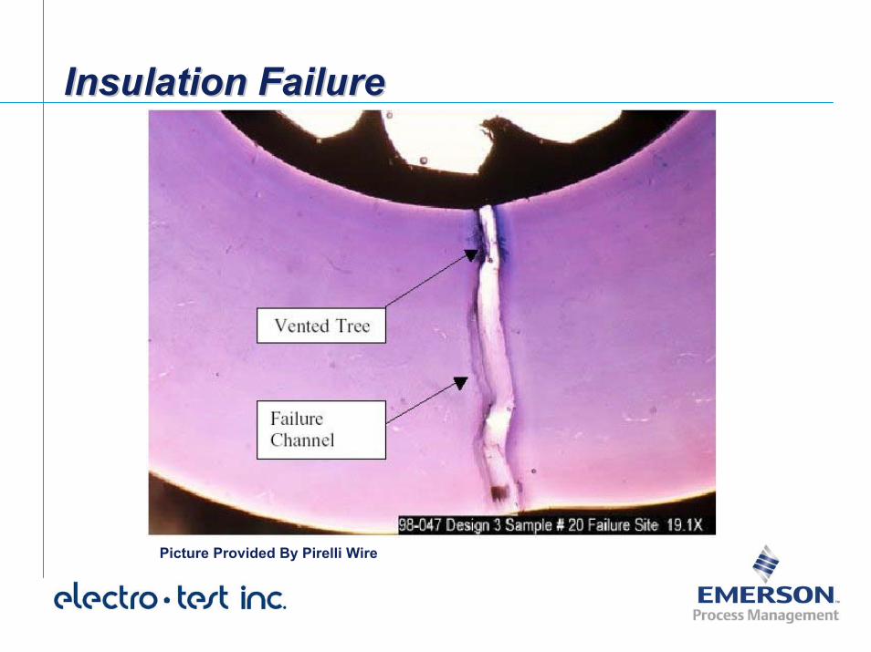
Insulation FailureInsulation FailureInsulation Failure
Picture Provided By Pirelli Wire
Failures in Cable AccessoriesFailures in Cable AccessoriesFailures in Cable Accessories
The majority of failures on distribution systems occur in terminations, splices and other cable accessories.
Failure mechanisms reported in Cable Accessories are predominantly involve Partial Discharge Deterioration caused by voids, contaminants and workmanship problems.
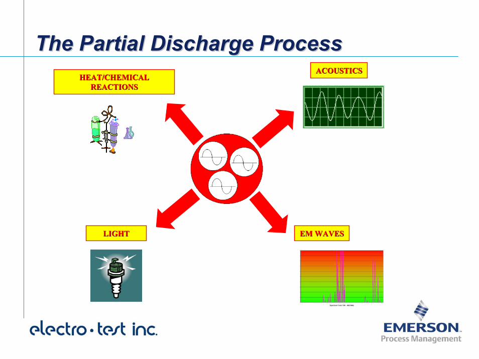
The Partial Discharge ProcessThe Partial Discharge ProcessACOUSTICSACOUSTICS
HEAT/CHEMICAL HEAT/CHEMICAL REACTIONSREACTIONS
LIGHTLIGHT EM WAVESEM WAVES
IEEE Standard 400-2001 Notes:IEEE Standard 400IEEE Standard 400--2001 Notes:2001 Notes:
“Partial discharge measurement is an important method of assessing the quality of the insulation of power cable systems…”
“A partial discharge is an electrical discharge (formation of a streamer or arc) that does not bridge the entire space between two electrodes.”
Partial discharges may occur in a “void…at a contaminant…or at the tip of a well-developed water tree...”
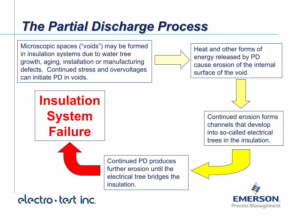
The Partial Discharge ProcessThe Partial Discharge ProcessMicroscopic spaces (“voids”) may be formed in insulation systems due to water tree growth, aging, installation or manufacturing defects. Continued stress and overvoltagescan initiate PD in voids.
Heat and other forms of energy released by PD cause erosion of the internal surface of the void.
Continued erosion forms channels that develop into so-called electrical trees in the insulation.
Insulation System Failure
Continued PD produces further erosion until the electrical tree bridges the insulation.
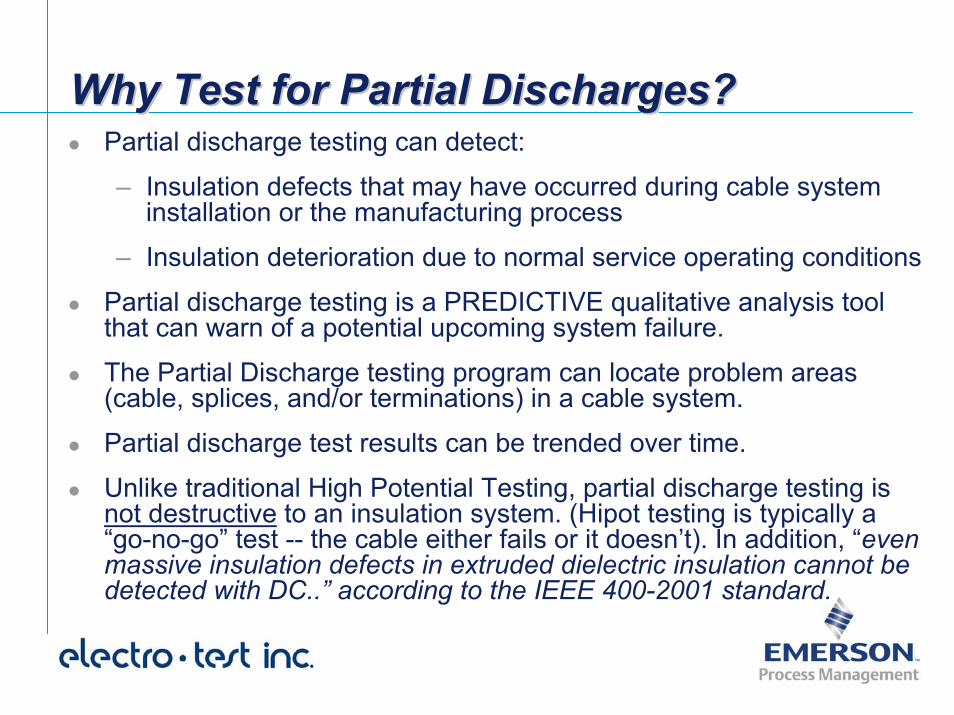
Why Test for Partial Discharges?Why Test for Partial Discharges?Why Test for Partial Discharges?Partial discharge testing can detect:
– Insulation defects that may have occurred during cable system installation or the manufacturing process
– Insulation deterioration due to normal service operating conditions
Partial discharge testing is a PREDICTIVE qualitative analysis tool that can warn of a potential upcoming system failure.
The Partial Discharge testing program can locate problem areas (cable, splices, and/or terminations) in a cable system.
Partial discharge test results can be trended over time.
Unlike traditional High Potential Testing, partial discharge testing is not destructive to an insulation system. (Hipot testing is typically a “go-no-go” test -- the cable either fails or it doesn’t). In addition, “even massive insulation defects in extruded dielectric insulation cannot be detected with DC..” according to the IEEE 400-2001 standard.
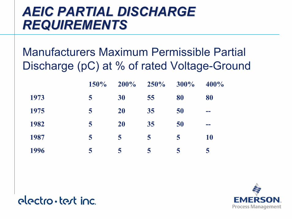
AEIC PARTIAL DISCHARGE REQUIREMENTSAEIC PARTIAL DISCHARGE AEIC PARTIAL DISCHARGE REQUIREMENTSREQUIREMENTS
Manufacturers Maximum Permissible PartialDischarge (pC) at % of rated Voltage-Ground
150% 200% 250% 300% 400%
1973 5 30 55 80 80
1975 5 20 35 50 --
1982 5 20 35 50 --
1987 5 5 5 5 10
1996 5 5 5 5 5
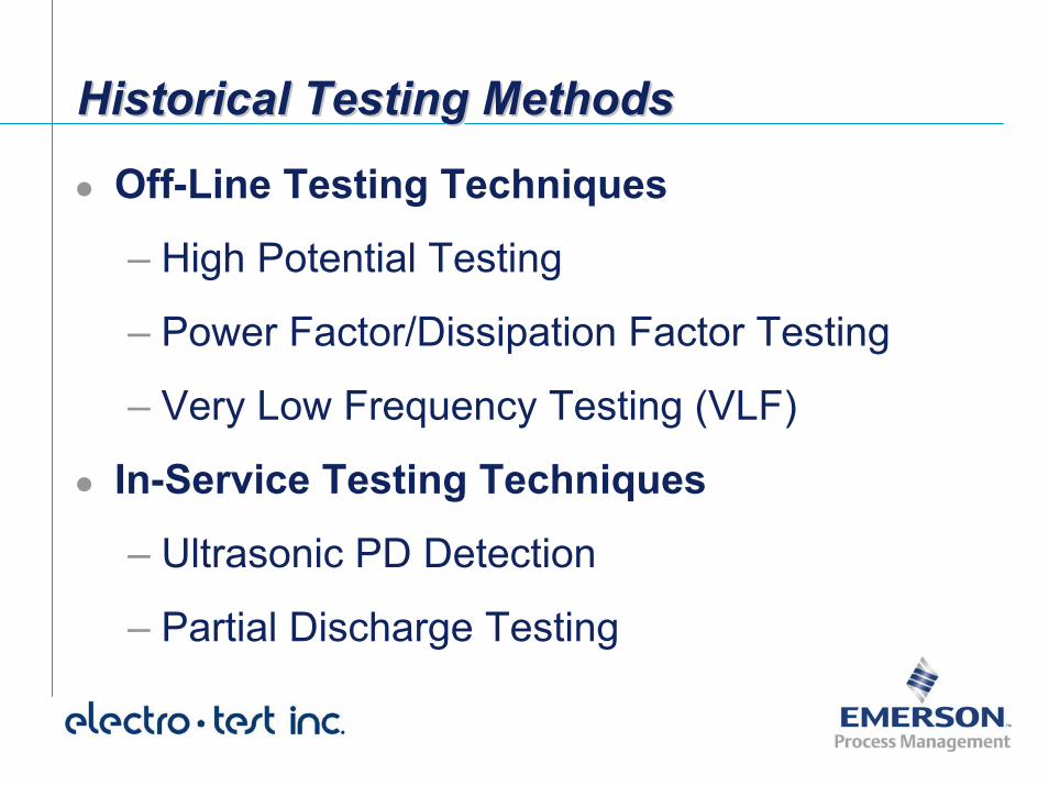
Historical Testing MethodsHistorical Testing MethodsHistorical Testing Methods
Off-Line Testing Techniques
– High Potential Testing
– Power Factor/Dissipation Factor Testing
– Very Low Frequency Testing (VLF)
In-Service Testing Techniques
– Ultrasonic PD Detection
– Partial Discharge Testing
Off-Line Testing TechniquesOffOff--Line Testing TechniquesLine Testing TechniquesRequire de-energization of the cable under test and in some cases, completely removed from the distribution system.
Has the advantage of close control of the test voltage, and if necessary raising the voltages above the normal operation voltage.
Disconnecting from system and using a special voltage also minimizes noise, reducing the need for filtering and intense data interpretation.
High Potential Testing - DCHigh Potential Testing High Potential Testing -- DCDCIEEE, Electric Power Research Institute (EPRI), Insulated Cable
Engineers Association (ICEA), and Association of Edison Illuminating Companies (AEIC) all agree on the following:
• “DC High Potential Maintenance Testing on aged (XLP) cables can damage the cable resulting in premature failure”
• “High Voltage DC Tests continue to be useful tests to check systems before they are placed in service. When used as maintenance tests the possibility of damage to the cable should be considered.”
• “Cable Manufacturer’s must be consulted to determine acceptable voltage levels and recommendations typically include to test at your own risk”
High Potential Testing - DCHigh Potential Testing High Potential Testing -- DCDC
• IEEE 400-2001 standard:
• "...even massive insulation defects in extruded dielectric insulation cannot be detected with DC at the recommended voltage levels."
In other words -- not only is DC High Potential testing likely destructive for field-aged extruded cables, but it may not tell you a darn thing.
High Potential Testing - DCHigh Potential Testing High Potential Testing -- DCDC
WHAT’S THE BOTTOM LINE SKIP??????????
QUIT DC HIPOT QUIT DC HIPOT TESTINGTESTING
Power Factor/Dissipation Factor TestingPower Factor/Dissipation Factor TestingPower Factor/Dissipation Factor Testing
Effective in locating weaknesses in insulation and potential hazards before impending failure.
Not a “Go-No-Go” Test
Testing does not overstress the insulation and can determine if the insulation is slowly degrading through trending.
Testing limited to relatively short lengths of cables.
Not effective in detecting localized faults as the length of cable increases.
Very Low Frequency (VLF) TestingVery Low Frequency (VLF) TestingVery Low Frequency (VLF) Testing
VLF - High Potential Testing– VLF damages the insulation less than DC Testing and has the
capability of locating potential failure sites.
– VLF has the advantage of portability with low energy requirements, which results in much smaller test sets.
VLF Partial Discharge Testing– Voltage is raised to above the PD inception voltage to cause PD
to occur. PD is then locatable using Time Domain PD Detection methods.
– Cable must be disconnected to test.
In-Service Testing TechniquesInIn--Service Testing TechniquesService Testing Techniques
Has the obvious advantage that the cable is not put at any additional risk from the test.
Technique has the advantage that the cable is not removed from service, leaving it energized as it is for normal operation
Removes the potential for damage due to inappropriate switching and yields no system contingency problems
Ultrasonic PD TestingUltrasonic PD TestingUltrasonic PD Testing
Can pinpoint a suspected problem if the cable or accessory is not directly buried or is at least physically accessible
The high-frequency ultrasonic components of PD are extremely short wave in nature, fairly directional and easy to isolate from background noise
Problem must be accessible
On-Line Partial Discharge Testing System for Cable SystemsOnOn--Line Partial Discharge Testing Line Partial Discharge Testing System for Cable SystemsSystem for Cable Systems
There is zero down time associated with On-Line PD testing because the the test is performed at normal operating voltage. Testing involves no external voltage or current sources.
Test equipment measures PD produced at voltages of 2400 volts and greater.
The system is independent of load current.
It is non-invasive testing that does not inject current into the system, nor does it subject the system to excessive voltage levels.
Method is 100% non-destructive and 100% non-invasive.
On-Line Partial Discharge Testing SystemOnOn--Line Partial Discharge Testing Line Partial Discharge Testing SystemSystem
Two Part System Study
On-Site System Study Off-Site System StudyPartial Discharge activity is recorded from several Points of Attachment (POA’s) along the length of each cable run.
If possible, the sensors are clamped around all three phases at once.
In general, it is preferred to attach sensors every 500 ft.
Partial Discharge data is processed utilizing pattern recognition software and analysis.
Analysis is used to formulate a final report, which details findings.
Final Report detailing the analysis of system is delivered.
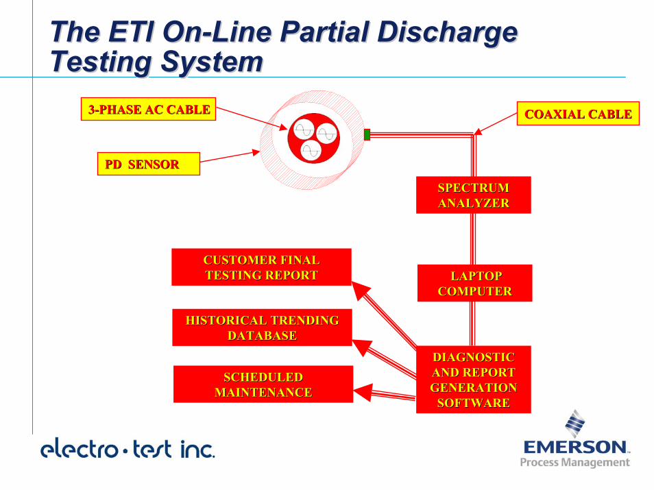
The ETI On-Line Partial Discharge Testing SystemThe ETI OnThe ETI On--Line Partial Discharge Line Partial Discharge Testing SystemTesting System
SPECTRUM SPECTRUM ANALYZERANALYZER
LAPTOP LAPTOP COMPUTERCOMPUTER
33--PHASE AC CABLEPHASE AC CABLE COAXIAL CABLECOAXIAL CABLE
PD SENSORPD SENSOR
CUSTOMER FINAL CUSTOMER FINAL TESTING REPORTTESTING REPORT
HISTORICAL TRENDING HISTORICAL TRENDING DATABASEDATABASE
DIAGNOSTIC DIAGNOSTIC AND REPORT AND REPORT GENERATION GENERATION
SOFTWARE
SCHEDULED SCHEDULED MAINTENANCEMAINTENANCE
SOFTWARE
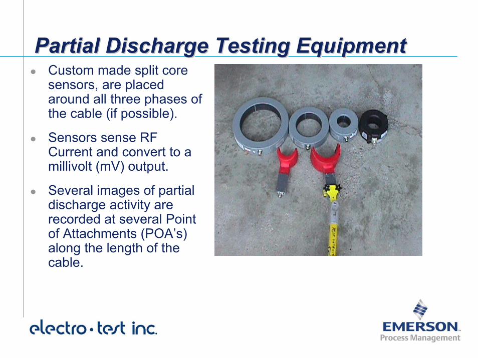
Partial Discharge Testing EquipmentPartial Discharge Testing EquipmentPartial Discharge Testing EquipmentCustom made split core sensors, are placed around all three phases of the cable (if possible).
Sensors sense RF Current and convert to a millivolt (mV) output.
Several images of partial discharge activity are recorded at several Point of Attachments (POA’s) along the length of the cable.
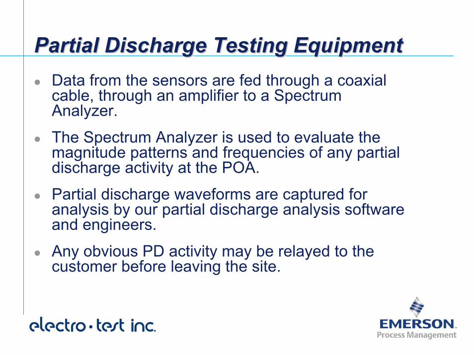
Partial Discharge Testing EquipmentPartial Discharge Testing EquipmentPartial Discharge Testing EquipmentData from the sensors are fed through a coaxial cable, through an amplifier to a Spectrum Analyzer.
The Spectrum Analyzer is used to evaluate the magnitude patterns and frequencies of any partial discharge activity at the POA.
Partial discharge waveforms are captured for analysis by our partial discharge analysis software and engineers.
Any obvious PD activity may be relayed to the customer before leaving the site.
Partial Discharge PredictionsPartial Discharge PredictionsPartial Discharge Predictions
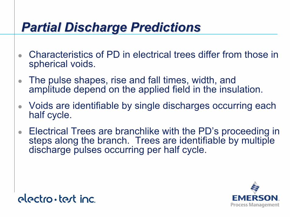
Characteristics of PD in electrical trees differ from those in spherical voids.
The pulse shapes, rise and fall times, width, and amplitude depend on the applied field in the insulation.
Voids are identifiable by single discharges occurring each half cycle.
Electrical Trees are branchlike with the PD’s proceeding in steps along the branch. Trees are identifiable by multiple discharge pulses occurring per half cycle.
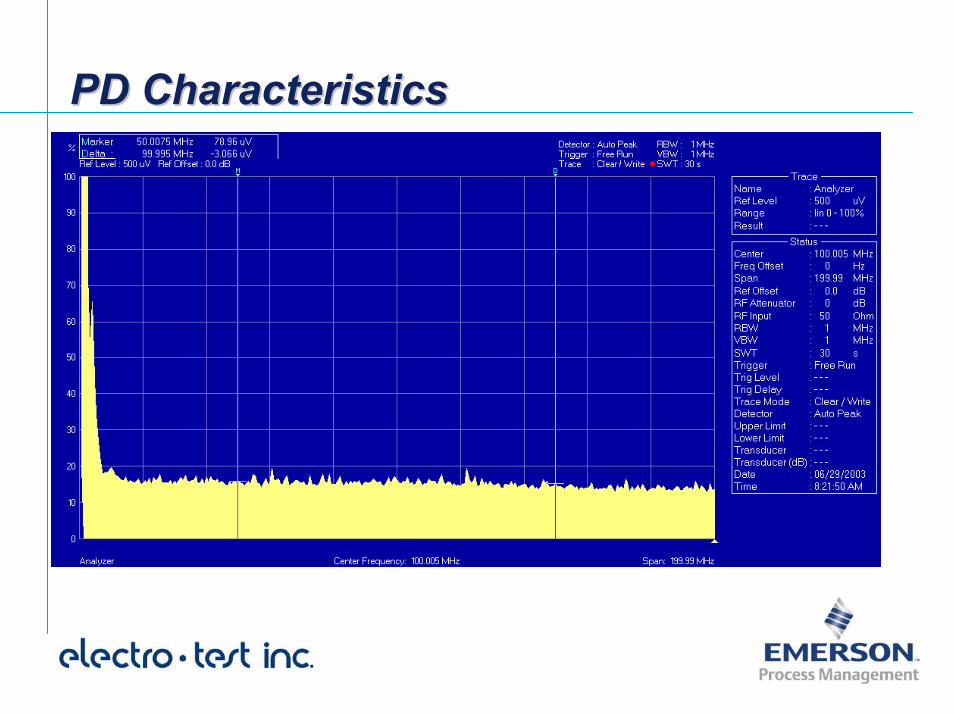
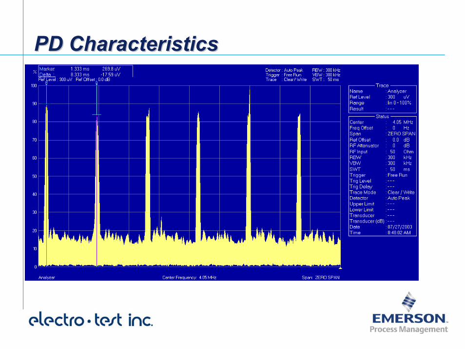
PD CharacteristicsPD CharacteristicsPD Characteristics
Electrical TreeingCorona and/or VoidsCorona/Voids
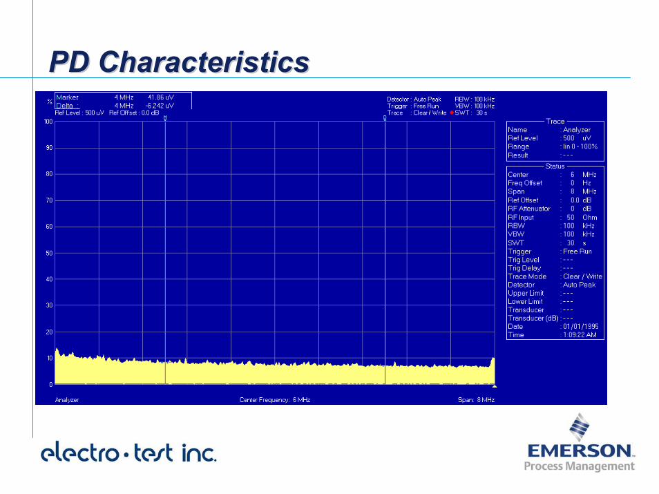
PD CharacteristicsPD CharacteristicsPD Characteristics
Electrical TreeingCorona and/or VoidsCorona/Voids
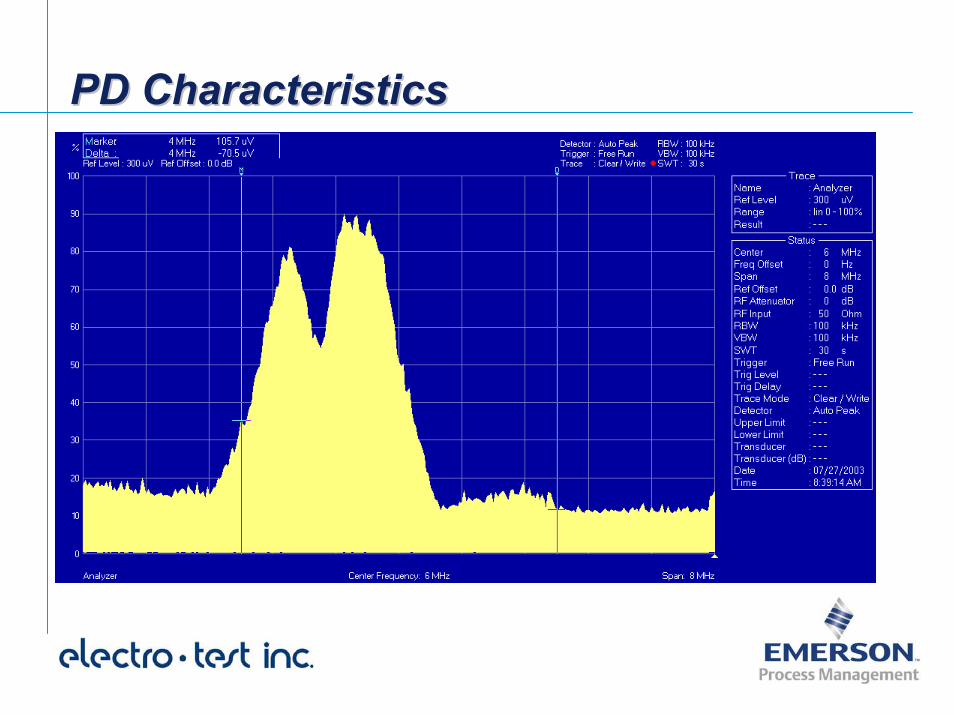
PD CharacteristicsPD CharacteristicsPD Characteristics
Electrical TreeingCorona and/or VoidsCorona/Voids
PD CharacteristicsPD CharacteristicsPD Characteristics
Electrical TreeingElectrical Treeing
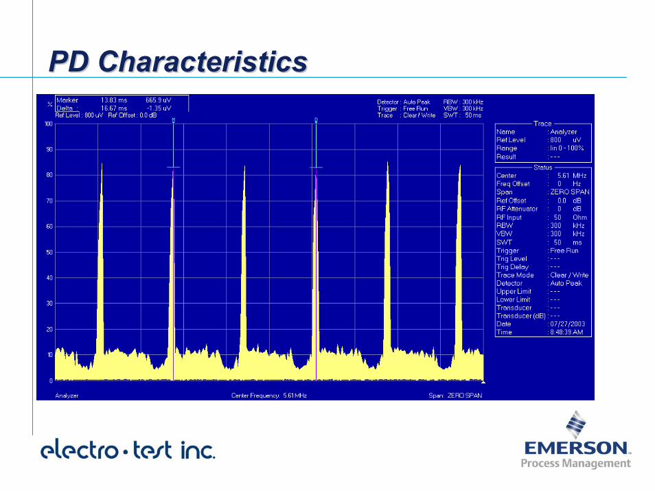
PD CharacteristicsPD CharacteristicsPD Characteristics
Electrical TreeingElectrical Treeing
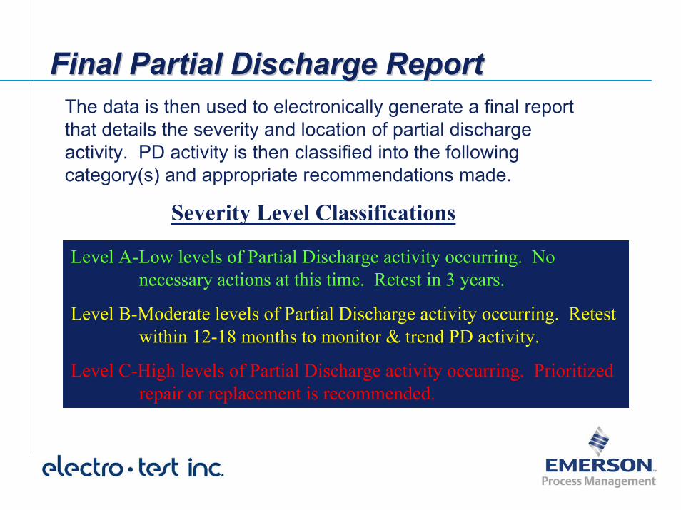
Final Partial Discharge ReportFinal Partial Discharge ReportFinal Partial Discharge ReportThe data is then used to electronically generate a final report that details the severity and location of partial discharge activity. PD activity is then classified into the following category(s) and appropriate recommendations made.
Severity Level Classifications
Level A-Low levels of Partial Discharge activity occurring. No necessary actions at this time. Retest in 3 years.
Level B-Moderate levels of Partial Discharge activity occurring. Retestwithin 12-18 months to monitor & trend PD activity.
Level C-High levels of Partial Discharge activity occurring. Prioritized repair or replacement is recommended.
Final Partial Discharge ReportFinal Partial Discharge ReportFinal Partial Discharge ReportSoftware has been developed for pattern recognition and conversion of data to usable format. Software significantly reduces the amount of time required to generate a final report.
Reports can show the severity level of any observed partial discharge activities, where they are located, recommended testing intervals, other recommended actions, etc.
In addition, the final report can provide the actual data used to formulate our recommendations.
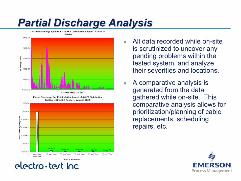
Partial Discharge AnalysisPartial Discharge AnalysisPartial Discharge AnalysisAll data recorded while on-site is scrutinized to uncover any pending problems within the tested system, and analyze their severities and locations.
A comparative analysis is generated from the data gathered while on-site. This comparative analysis allows for prioritization/planning of cable replacements, scheduling repairs, etc.
Success StoriesSuccess StoriesSuccess StoriesMichigan Department of Corrections - St. Louis Correctional Facility– Tuesday - Identified “Level C” Y-Splice located in
PMH feeding 5KV Padmount Transformer -Recommended Prioritized Replacement
– Friday - Y-Splice violently fails before facility could replace causing unplanned outage
• 5KV Distribution System was less than 2 years old and failure determined to be workmanship related on the Y-Splice

Success StoriesSuccess StoriesSuccess StoriesMichigan Department of Corrections -Bellamy Creek Correctional Facility– Performed On-Line Partial Discharge Testing to establish
baseline data for facility upon completion of Acceptance Testing.
– 15KV Distribution System Passed Acceptance Testing that consisted of AC High Potential Testing
– On-Line Partial Discharge Testing found a workmanship defect at a Transformer Termination which was not found by High Potential Testing.
Success StoriesSuccess StoriesSuccess StoriesDisneyland Resort– Performed On-Line Partial Discharge Testing to evaluate
condition of 30 year old 1000 ft. 5KV XLPE WTF Feed.
– Testing was performed during normal plant production with zero down time.
– Discovered severe electrical treeing throughout 100 ft length of feed.
– Facility scheduled replacement with zero impact on Resort Operations.
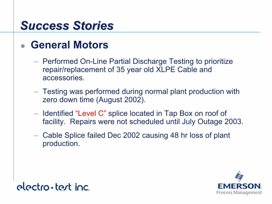
Success StoriesSuccess StoriesSuccess StoriesGeneral Motors– Performed On-Line Partial Discharge Testing to prioritize
repair/replacement of 35 year old XLPE Cable and accessories.
– Testing was performed during normal plant production with zero down time (August 2002).
– Identified “Level C” splice located in Tap Box on roof of facility. Repairs were not scheduled until July Outage 2003.
– Cable Splice failed Dec 2002 causing 48 hr loss of plant production.
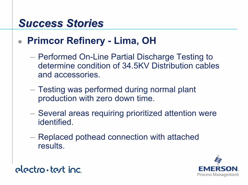
Success StoriesSuccess StoriesSuccess StoriesPrimcor Refinery - Lima, OH– Performed On-Line Partial Discharge Testing to
determine condition of 34.5KV Distribution cables and accessories.
– Testing was performed during normal plant production with zero down time.
– Several areas requiring prioritized attention were identified.
– Replaced pothead connection with attached results.
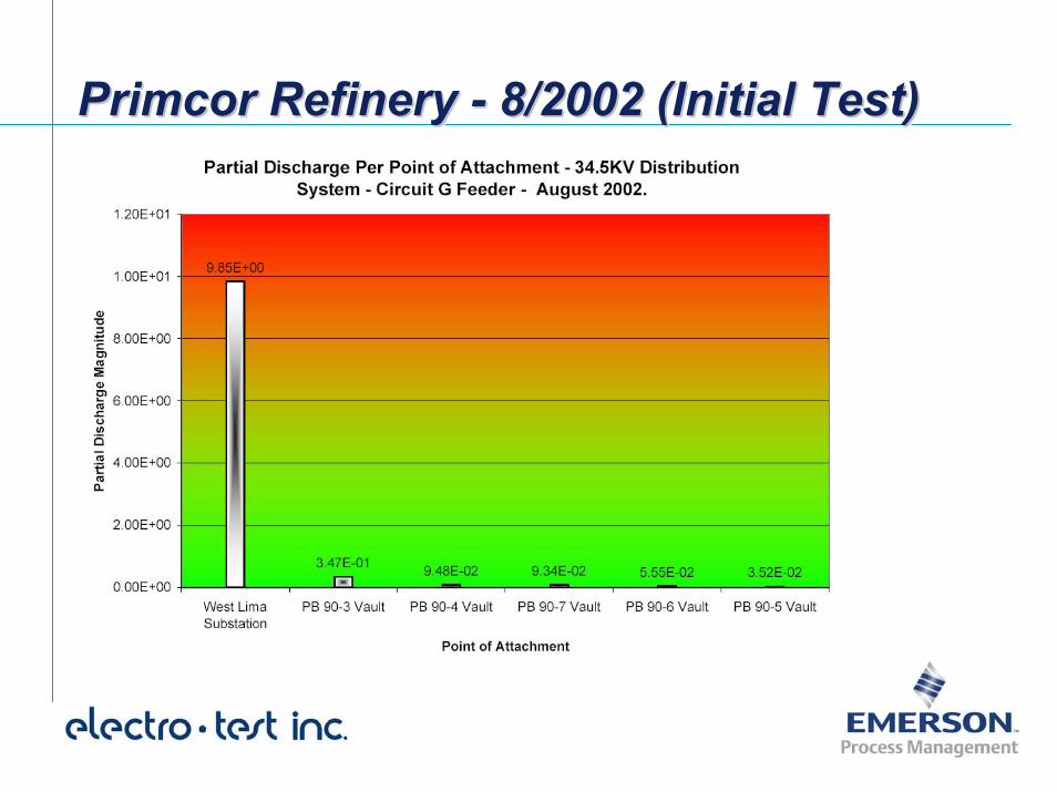
Primcor Refinery - 8/2002 (Initial Test)Primcor Refinery Primcor Refinery -- 8/2002 (Initial Test)8/2002 (Initial Test)
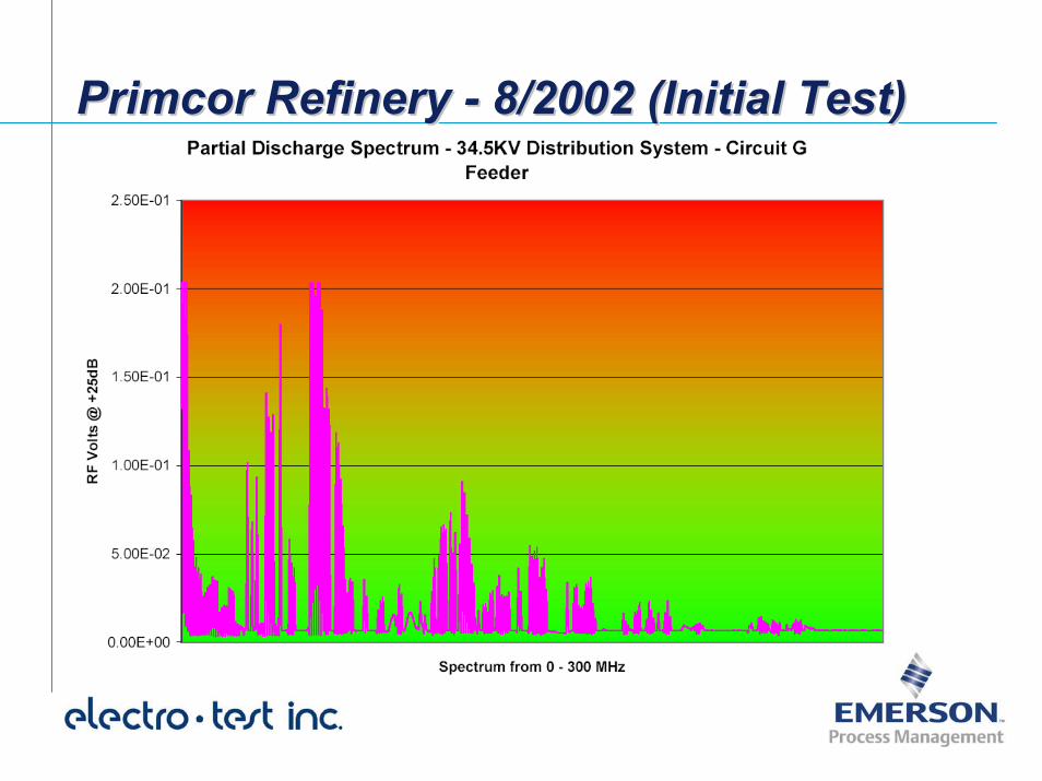
Primcor Refinery - 8/2002 (Initial Test)Primcor Refinery Primcor Refinery -- 8/2002 (Initial Test)8/2002 (Initial Test)
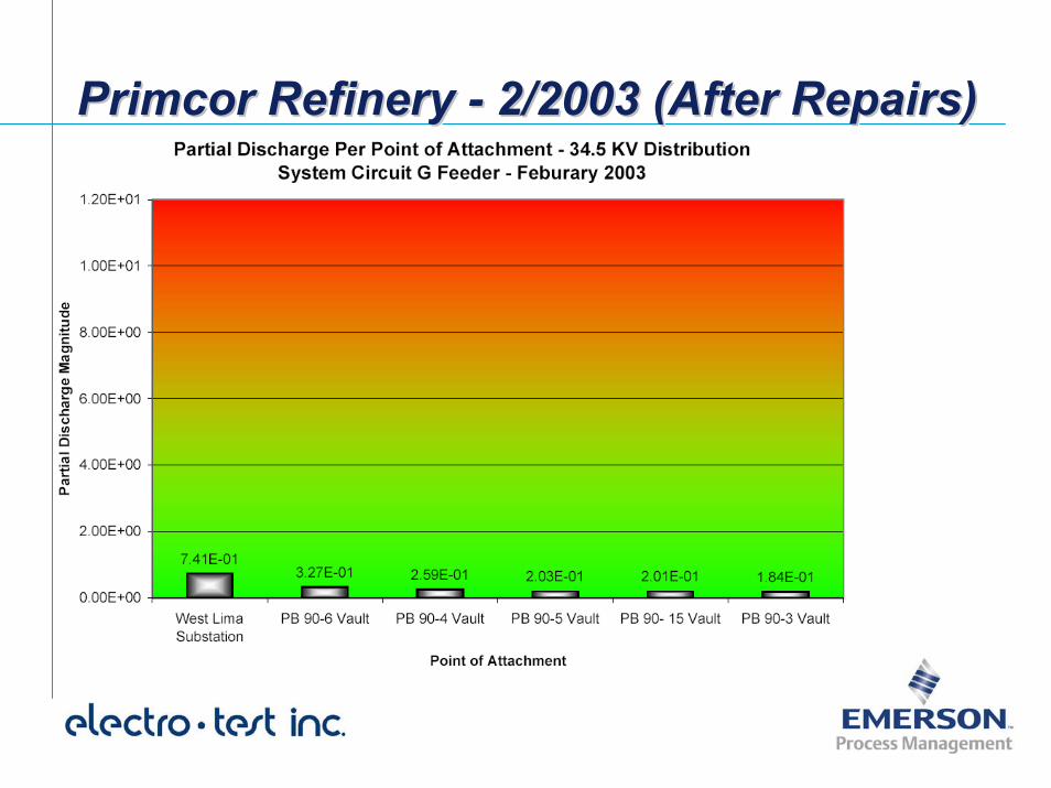
Primcor Refinery - 2/2003 (After Repairs)Primcor Refinery Primcor Refinery -- 2/2003 (After Repairs)2/2003 (After Repairs)
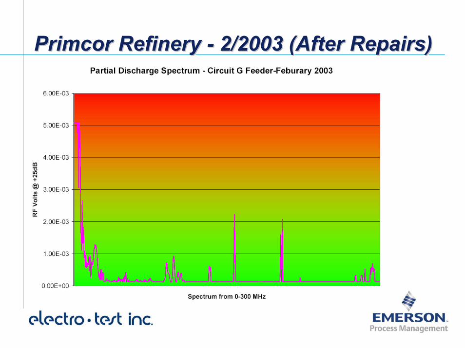
Primcor Refinery - 2/2003 (After Repairs)Primcor Refinery Primcor Refinery -- 2/2003 (After Repairs)2/2003 (After Repairs)
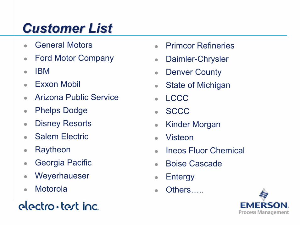
Customer ListCustomer ListCustomer ListGeneral MotorsFord Motor CompanyIBMExxon MobilArizona Public ServicePhelps DodgeDisney ResortsSalem ElectricRaytheonGeorgia PacificWeyerhaueserMotorola
Primcor RefineriesDaimler-ChryslerDenver CountyState of MichiganLCCCSCCCKinder MorganVisteonIneos Fluor ChemicalBoise CascadeEntergyOthers…..
SummarySummarySummary
On-Line Partial Discharge Testing is a non-invasive, non-destructive, predictive test procedure.
Testing is performed while plant remains on-line, completely eliminating the need for an outage.
Two part process consisting of both on-site data gathering and off-site system analysis.
Final report generated which provides interpretations and recommended actions.
ReferencesReferencesReferences[1] S.A. Boggs, R.J. Densley, “Fundamentals of Partial Discharge in the Context of Field Cable Testing”, IEEE Electrical
Insulation Magazine, Vol 16, No. 5
[2] S.A. Boggs, R.J. Densley, and J. Kuang, “Mechanism of Conversion of Water Trees to Electrical Trees under Impulse Conditions”, IEEE Trans. PD-13, No. 2, April 1998, pp. 310 - 315
[3] H. Hu, “Evaluation of Discharge Resistance of Solid Dielectric Power Cable Insulations”, IEEE Electrical Insulation Magazine, Vol 11, No. 2
[4] Dr. M. Brown, “EPR-Based URD Insulation - A Question of Confidence”, IEEE Electrical Insulation Magazine, Vol 4, No. 5
[5] R. DiLorenzo, F. Krajick, S. Boggs, J. Ronzello, G. Pehlert, R. Dharmarajan, G. Fridland, R. Annicelli, “Comparison of AC Impulse Breakdown of Model EPR and TR-XLPE Cables as a Function of Wet Electrical Aging”, PES ICC, April 2002
[6] Boggs, S.A. “Mechanisms for Reduction of Impulse Strength Resulting from Small Water Trees”. 2000 Annual Report of the IEEE Conference on Electrical Insulation and Dielectric Phenomena. pp. 547-551. (also submitted for review to Trans PD.)
[7] C. Laurent, C. Mayoux, “Limitations to PD as a Diagnostic for Deterioration and Remaining Life”, IEEE Electrical Insulation Magazine, Vol 8, No. 2
[8] F.H. Kreuger, M.G. Wezelenburg, A.G. Wiemer, W.A. Sonneveld, “Errors in the Location of Partial Discharges in High Voltage Solid Dielectric Cables”, IEEE Electrical Insulation Magazine, Vol 9, No. 6
[9] S. Boggs, J. Xu, “Water Treeing - Filled vs Unfilled Cable Insulation”, EIRC