Embed Size (px)
Citation preview
On IP Networking over Tactical Links
Claude Bilodeau
The work described in this document was sponsored by the Department of National Defence under Work Unit 5co.
Defence R&D Canada √ Ottawa TECHNICAL REPORT
DRDC Ottawa TR 2003-099
Communications Research Centre CRC-RP-2003-008
August 2003

On IP networking over tactical links
Claude BilodeauCommunications Research Centre
The work described in this document was sponsored by the Department of National Defence under Work Unit 5co.
Defence R&D Canada - OttawaTechnical Report
DRDC Ottawa TR 2003-099
Communications Research CentreCRC RP-2003-008
August 2003

© Her Majesty the Queen as represented by the Minister of National Defence, 2003
© Sa majesté la reine, représentée par le ministre de la Défense nationale, 2003
Abstract
This report presents a cross section or potpourri of the numerous issues that surround the tech-nical development of military IP networking over disadvantaged network links. In the first sec-tion, multi-media services are discussed with regard to three aspects: applications, operational characteristics and service models. The second section focuses on subnetworks and bearers; mainly impairments caused by characteristics of the wireless environment. An overview of the Iris tactical bearers is provided as an example of a tactical IP environment. The last section looks at how IP can integrate these two elements i.e. multi-media services and impaired sub-network links. These three sections are unified by a common theme, quality of service, which runs in the background of the discussions.
Résumé
Ce rapport présente une coupe transversale ou pot-pourri de questions reliées au développe-ment technique des réseaux militaires IP pour des liaisons défavorisées. La première partie porte sur les services réseaux de type multimédia. On y discute des applications, des caractéris-tiques fonctionnelles, et de la modélisation des services. La seconde partie se concentre sur les sous-réseaux et les causes possibles de leur défaillance, principalement celles imputables aux caractéristiques des transmissions sans fil. Un bref aperçu du système Iris de l’armée cana-dienne est inclus et présenté en guise d’exemple de réseau tactique IP. En dernière partie, on examine l’intégration de ces deux éléments aux systèmes IP i.e. les services réseaux de type multimédia et les sous-réseaux opérants des liaisons défavorisées. La qualité de service est un thème récursif discuté en arrière-plan et qui sert de toile de fond, unifiant ces trois parties.
iiiDRDC Ottawa TR 2003-099; CRC RP-2003-008

This page intentionally left blank.
iv DRDC Ottawa TR 2003-099; CRC RP-2003-008

Executive summary
Introduction
The delivery of military multi-media services over IP based tactical networks offers the pros-pect of ubiquitous real-time information sharing across the levels of command and on the bat-tlefield. Propelled by IP, the most widely used internetworking protocol, the Internet knows a commercial success that is phenomenal. However, IP is not without its problems, especially when used in a military environment. This report presents a selection of system issues that sur-round the technical development of IP networking over military links. Looking at the broad context of IP networking in general, the high-level trends and directions are also discussed.
The review
In the space available, this report can only scratch the surface of IP’s integration and dynamic. In Chapter 1, the emphasis is on multi-media services, which are discussed with regard to three aspects: applications, operational characteristics and service models. The author looks at the different ways traffic sources are most often classified or characterized and how modern appli-cations are integrated to the network protocol stacks. Chapter 2 focuses on subnetworks and bearers; mainly impairments caused by characteristics of the wireless environment i.e. channel error, bandwidth limitation and transmission delay. An overview of the Iris tactical bearers is provided as an example of a tactical IP environment. Chapter 3 looks at how IP can integrate these two elements i.e. multi-media services and impaired subnetwork links. These three chap-ters are unified by a common theme, quality of service, which runs in the background of the discussions.
The stakes
The review highlights the abundance of clever proposals and creative solutions, which in a way reflect both the weaknesses and strengths of IP. It is observed that a great deal of the many challenges facing the integration of graded services at the IP layer revolve around various tech-niques trading off the best effort packet delivery approach for schemes that are path or flow ori-ented. By doing so, network robustness, simplicity, transparency and other design objectives originally part of the Internet design philosophy are potentially weakened or compromised.
Focusing the development of tactical networks on just one switching technology leads to better interoperability and system integration, which no doubt are important considerations. How-ever, one should keep an eye on the development of a diversity of avenues so as to minimize the risk of latent vulnerabilities typically found in any single solution.
Bilodeau, C. 2003. On IP networking over tactical links. DRDC Ottawa TR 2003-099; CRC RP-2003-008. Defence R&D Canada - Ottawa.
vDRDC Ottawa TR 2003-099; CRC RP-2003-008

This page intentionally left blank.
vi DRDC Ottawa TR 2003-099; CRC RP-2003-008
Sommaire
Introduction
La venue de services réseaux de type multimédia permet d’envisager un partage omniprésent d’information en temps réel au sein des déploiements de forces tactiques et la chaîne de com-mandement d’une armée. Grâce à IP —le protocole d’interconnexion de réseaux le plus large-ment répandu— l’Internet connaît un succès commercial des plus phénoménal. IP ne vient cependant pas sans problèmes, surtout lorsqu’il est utilisé dans un environnement de réseaux militaires. Ce rapport analyse un assortiment de questions reliées au développement technique des réseaux militaires axés sur le protocole IP. Les tendances et les vues dominantes que l’on peut observer concernant le réseautage IP en général sont également discutées.
L’étude
Par souci d’économie d’espace, ce rapport ne peut qu’esquisser dans ses grandes lignes la dynamique et l’intégration des systèmes IP. Le premier chapitre porte sur les services réseaux de type multimédia. On y discute des applications, des caractéristiques fonctionnelles, et de la modélisation des services. On y examine les diverses façons dont les sources génératrices d’information sont classifiées et caractérisées, ainsi que comment aujourd’hui ces applications sont intégrées aux piles de protocoles des réseaux. Le seconde chapitre se concentre sur les sous-réseaux et les causes possibles de leur défaillance, principalement celles imputables aux caractéristiques des transmissions sans fil i.e. erreur, délai et coercition de la largeur de bande du canal de transmission. Un bref aperçu du système Iris de l’armée canadienne est inclus et présenté en guise d’exemple de réseau tactique IP. Au troisième chapitre, on examine l’intégra-tion de ces deux éléments aux systèmes IP i.e. les services réseaux de type multimédia et les sous-réseaux assujettis à des liaisons défavorisées. La qualité de service est un thème récursif utilisé comme toile de fond, discuté en arrière-plan, et unifiant ainsi ces trois chapitres.
Les enjeux
L’étude fait ressortir une multiplicité de propositions astucieuses et de solutions innovatrices, reflétant d’une certaine façon, les forces et faiblesses du protocole IP. Le constat est que l’intégration du contrôle de la qualité des services au niveau de la couche réseau IP fait appel à de nombreux défis qui, pour la plupart, relèvent de diverses techniques où l’on concède l’approche de routage par paquet du type “meilleur effort” pour des stratagèmes d’achemine-ment par flux ou par parcours. Ce faisant, la résilience du réseau, sa transparence de bout en bout, ainsi que d’autres objectifs et caractéristiques faisant originalement partie de la philoso-phie de conception de l’Internet, sont potentiellement diminués ou compromis.
De concentrer le développement des réseaux tactiques sur une seule technologie de commuta-tion permet une meilleure intégration et facilite l’interopérabilité des systèmes. De telles con-sidérations sont sans contredit importantes. Cependant, il est de mise de surveiller le
viiDRDC Ottawa TR 2003-099; CRC RP-2003-008

développement d’avenues parallèles afin de diversifier et de minimiser le risque d’être exposé aux vulnérabilités latentes que l’on retrouve typiquement chez toute solution monolithique.
Bilodeau, C. 2003. On IP networking over tactical links. DRDC Ottawa TR 2003-099; CRC RP-2003-008. Defence R&D Canada - Ottawa.
viii DRDC Ottawa TR 2003-099; CRC RP-2003-008

Table of contents
Abstract ................................................................................................................................... iii
Résumé ................................................................................................................................... iii
Executive summary ................................................................................................................. v
Introduction ................................................................................................................ vThe review .................................................................................................................. vThe stakes ................................................................................................................... v
Sommaire ............................................................................................................................... vii
Introduction .............................................................................................................. viiL’étude ...................................................................................................................... viiLes enjeux ................................................................................................................. vii
Table of contents .................................................................................................................... ix
List of figures ......................................................................................................................... xi
List of tables .......................................................................................................................... xii
Acknowledgements ............................................................................................................... xii
Introduction ............................................................................................................................. 1
A word about Iris 1st generation ................................................................................ 2
1. Multi-media services ........................................................................................................... 3
Application taste ......................................................................................................... 3FNBDT .......................................................................................................... 6WAP and BEEP: bells and whistles? ............................................................ 7Message Exchange Service (MXS) in Iris .................................................. 10Name Address Resolution Service (NARS) in Iris ..................................... 11SigComp ...................................................................................................... 12
Operational characteristics ....................................................................................... 12Service models ......................................................................................................... 14End-user services in Iris ........................................................................................... 16
2. Transmission environments ............................................................................................... 16
IP packet radio: a very long cat ................................................................................ 16Bearers in Iris ........................................................................................................... 18
Commonality of the LAN/LDN/TDN Protocols ......................................... 19Vehicle Local Area Network ....................................................................... 19Local Distribution Network ........................................................................ 19Iris Trunk Network ...................................................................................... 19CNR Subnetwork ........................................................................................ 20
3. IP-based integration ........................................................................................................... 21
ixDRDC Ottawa TR 2003-099; CRC RP-2003-008
Is IP a new religion? ................................................................................................. 21IP rules! ....................................................................................................... 22IP’s Achilles’ heel ....................................................................................... 23QoS, the great challenge .............................................................................. 24A total reversal of the Internet philosophy .................................................. 25ATM 5, IPv4 20, IPv6 40! ........................................................................... 26Are virtual circuits bad for tactical networks? ............................................ 27Location of control intelligence .................................................................. 31
Making IP work in problematic environments ......................................................... 34Coping with bandwidth constraint ........................................................................... 34
Increasing available bandwidth ................................................................... 34Reducing amount of traffic ......................................................................... 36Rerouting traffic .......................................................................................... 37Making better use of bandwidth .................................................................. 40
Coping with error impairments ................................................................................ 43Automatic Link Establishment (ALE) ........................................................ 43ARQ, FEC and TDC ................................................................................... 44TCP and its various flavours ....................................................................... 45
Coping with delay impairments ............................................................................... 50BCP for satellite channels ........................................................................... 50SCPS-TP and other PEPs ............................................................................ 52SCOPE ........................................................................................................ 52Long Thin Networks (LTN) ........................................................................ 53
QoS in Iris ................................................................................................................ 55Bandwidth allocation and dynamic routing ................................................ 55Traffic prioritization .................................................................................... 55
Conclusion ............................................................................................................................. 56
Reference ............................................................................................................................... 57
Acronyms and initialisms ...................................................................................................... 59
x DRDC Ottawa TR 2003-099; CRC RP-2003-008
List of figures
Figure 1. Main themes (by chapter ) discussed in this report ................................................ 1
Figure 2. Official protocols required or recommended in the Internet in April 1983 (from RFC 840) ................................................................................................................ 5
Figure 3. Internet multimedia conferencing protocol stacks [2]: a dream for the strategic and tactical environments? ............................................. 6
Figure 4. Simplified FNBDT Protocol Stack ......................................................................... 7
Figure 5. WAP protocol stack ................................................................................................ 8
Figure 6. WAP client-server architecture optimised for low-capacity links ......................... 8
Figure 7. Placement of MXS in Iris protocol stack ............................................................. 10
Figure 8. Taxonomy of applications .................................................................................... 13
Figure 9. IP Application/Service model used in ITU-T Recommendation Y.1001 [12] ..... 14
Figure 10. ATM Application/Service model specified by the ATM Forum [13] .................. 15
Figure 11. Hybrid architectures require QoS mapping between different service models .... 15
Figure 12. Three categories of networks that are vulnerable to large delay-bandwidth products ................................................................................................................ 18
Figure 13. IP provides a connectionless datagram service with no guarantee of message delivery 24
Figure 14. Header overhead in ATM, IPv4, IPv6 .................................................................. 26
Figure 15. Internetwork general protocols (in bold) as assigned by IANA ........................... 28
Figure 16. A sample of conventional switching and multiplexing technologies used in networking ............................................................................................................ 29
Figure 17. Simple model of a packet switch (data plane) ...................................................... 32
Figure 18. Some building blocks derived from the coupling of the intrinsic functions in packet switching ............................................................................................................... 32
Figure 19. Progress in HF communications ........................................................................... 35
Figure 20. Multi-channel HF receiver: one option under study at CRC to increase the capability of HF systems 36
Figure 21. The well known “fish” topology .......................................................................... 38
Figure 22. QoS, the great challenge ....................................................................................... 41
Figure 23. In narrowband systems, there are few concurrent flows to manage. In such environ-ment, is there really a need for sophisticated priority/fair queuing schemes? ...... 43
Figure 24. The genuine raison d’être of TCP as specified in RFC 793 and some of the TCP flavours developed over the years ............................................ 46
Figure 25. Classification of satellite systems ......................................................................... 50
Figure 26. IP and ST-II bandwidth allocation ....................................................................... 56
xiDRDC Ottawa TR 2003-099; CRC RP-2003-008

List of tables
Table 1. Official protocols used in the Internet in April 1983 (from RFC 840) .................. 4
Table 2. Comparison of WAP and Internet protocols: WDP versus UDP ........................... 9
Table 3. Comparison of WAP and Internet protocols: WTP versus TCP ............................ 9
Table 4. Basic end-user services in Iris .............................................................................. 16
Table 5. IP’s built-in mechanisms for supporting QoS ...................................................... 26
Table 6. Assigned Internet version numbers ...................................................................... 28
Table 7. Some factors influencing choice of switching technology ................................... 30
Table 8. Comparison of datagram and virtual-circuit subnets [20] .................................... 30
Table 9. Comparison of ALE techniques [33] .................................................................... 44
Table 10. TCP-related RFCs trying to make TCP independent of the underlying network technology 49
Table 11. Summary of standard mitigation mechanisms ..................................................... 51
Table 12. Summary of PILC working group on recommended mechanisms for implementation in long thin networks (LTN)s ............................................................................... 54
Acknowledgements
This work was funded by Defence R&D Canada, Department of National Defence.
xii DRDC Ottawa TR 2003-099; CRC RP-2003-008
Introduction
Few will argue that IP now ranks 1st among the most famous and widely used internetworking protocols. It would be presumptuous to depreciate IP given the important role it plays in the phenomenal success of the Internet. Some may say that the conjunction of several other factors like the development of the Hyper Text Markup Language (HTML), the readily available Ber-keley-UNIX-based open source software for TCP/IP, Ethernet’s lowest cost network technol-ogy, etc., may have been seminal and vital catalysts in promoting IP to the level of renown the protocol enjoys today. However, regardless of its success, IP comes with a set of characteris-tics, some being unquestionably beneficial, others not so desirable to the advance of networked multi-media communications.
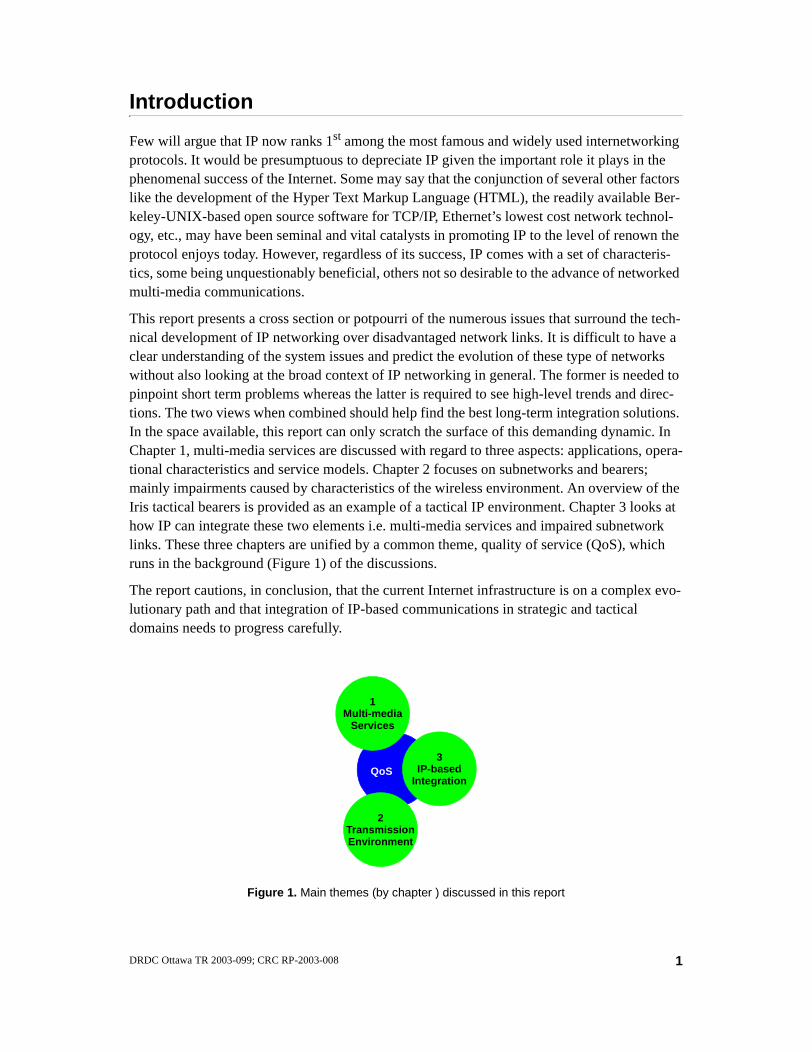
This report presents a cross section or potpourri of the numerous issues that surround the tech-nical development of IP networking over disadvantaged network links. It is difficult to have a clear understanding of the system issues and predict the evolution of these type of networks without also looking at the broad context of IP networking in general. The former is needed to pinpoint short term problems whereas the latter is required to see high-level trends and direc-tions. The two views when combined should help find the best long-term integration solutions. In the space available, this report can only scratch the surface of this demanding dynamic. In Chapter 1, multi-media services are discussed with regard to three aspects: applications, opera-tional characteristics and service models. Chapter 2 focuses on subnetworks and bearers; mainly impairments caused by characteristics of the wireless environment. An overview of the Iris tactical bearers is provided as an example of a tactical IP environment. Chapter 3 looks at how IP can integrate these two elements i.e. multi-media services and impaired subnetwork links. These three chapters are unified by a common theme, quality of service (QoS), which runs in the background (Figure 1) of the discussions.
The report cautions, in conclusion, that the current Internet infrastructure is on a complex evo-lutionary path and that integration of IP-based communications in strategic and tactical domains needs to progress carefully.
QoS
Figure 1. Main themes (by chapter ) discussed in this report
1Multi-media
Services
3IP-based
Integration
2TransmissionEnvironment
1DRDC Ottawa TR 2003-099; CRC RP-2003-008

A word about Iris 1st generation
At various occasions throughout the report, Iris, the Tactical Communication System for the Canadian Army, will be used to illustrate one particular approach among others.
This section provides a brief overview of the Iris System. In a nutshell, Iris is an integrated, hierarchical network performing all the functions necessary to enable the establishment, use, and maintenance of communications from the Division level headquarters down to soldiers in the field.
The Iris System may be described as a mobile communication system. Within a headquarters (comprising of a number of interconnected vehicles) subscribers have telephone (voice), data messaging (e-mail) and FAX facilities. Users may communicate with each others within the headquarters and between headquarters using the Iris Trunk Network. Headquarters and trunk network communication facilities are operational only when vehicles are stationary.
The Iris System handles integrated voice and IP data on a common network. This provides a highly mobile and agile system where only single links are required to establish voice and data communications quickly. Complex networks can be built incrementally from basic, indepen-dently deployable elements.
As mobility is a key requirement, most communications are performed over radio links. These links may be multi channel point-to-point (used in the Iris Trunk Network) or over Combat Net Radio (CNR). Most communication links have some form of encryption scheme that prevents eavesdropping. The CNR uses frequency hopping to reduce the possibility of jamming, as well as encryption.
The Iris System consists of:
• the Combat Net Radio (CNR) Segment — The CNR provides a half-duplex, “all-informed” communication where all users share the communication channel and it may be used for both voice and data. There are many CNR nets in deployment, each having a par-ticular purpose. The Primary CNR (CNR(P)) family of VHF radios form the principal means of communication for tactical groups at brigade level and below. The CNR segment also includes the hand-held, light weight Very Short Range Radio (VSRR), and the Air/Ground/Air and UHF radios.
• Headquarters Information Distribution System (HIDS) — The HIDS provides headquar-ters with a fully integrated voice and data network, which easily adapts to changing user configurations. The HIDS design offers a “connect anywhere” feature, which allows vehi-cles to be connected in a mesh to provide network robustness and link redundancy. HIDS also includes vehicle intercom systems.
• Long Range Communication System (LRCS) — The LRCS provides long range HF and satellite voice and data communication in secure and clear modes.
• Communication Management System (CMS) — The CMS is a distributed software sub-system used to plan, control and monitor the Iris network. It is executed on Portable Data Terminals (PDTs) located within a number of vehicles within a HQ.
• Tactical Message Handling System (TMHS) — TMHS is a distributed, secure X.400-based military message system. It is used to exchange data and computer files as messages
2 DRDC Ottawa TR 2003-099; CRC RP-2003-008
on a store and forward basis among Iris System subscribers equipped with PDTs and Field Data Terminals (FDTs), which is a hand held data device.
1. Multi-media services
The underlying theme of this report is the delivery of military multi-media services over IP based tactical networks. Multi-media applications have the property of simultaneously han-dling various types of related temporally and logically dependent content intended for presen-tation to one or more end-users. The deployment of these types of applications is relatively recent. Historically, applications were designed around the TCP/IP protocol suite and con-ceived to carry data information only. Today, some experts foresee that the IP technology will dominate the telecommunications industry over the next decade. The convergence of the data/computer and telecommunication industries brings about a wide range of new traffic streams. In this section, we look at the different ways traffic sources are most often classified or charac-terized and how modern applications are integrated to the network protocol stacks.
Application taste
The Internet architecture is specified by the Internet Engineering Task Force (IETF) through a series of Request for Comments (RFCs). From time to time, a list (STD 1) of official Internet protocol standards is issued to summarize the state of the system design and procedures. This measure started no less than 20 years ago and still is today being carried on periodically. Writ-ten by Jon Postel in April 1983, RFC 840 [1] identifies the documents specifying the official protocols used in the Internet when the first official list was issued at that time. Postel assigned each protocol to one of four pre-defined “status, or requirement levels” i.e. protocols that all hosts had to implement (required), protocols that all hosts were encouraged to implement (rec-ommended), protocols that hosts might implement or not (elective), and protocols that were still at an early development stage (experimental). For convenience, the protocols mentioned in RFC 840 are listed in Table 1 and those that were classified as “required” or “recommended” are pieced together graphically in Figure 2.
3DRDC Ottawa TR 2003-099; CRC RP-2003-008

Table 1. Official protocols used in the Internet in April 1983 (from RFC 840)
CATEGORY PROTOCOL RFC
STATUS (AS OF APR’83)
Req
uir
ed
Rec
om
men
ded
Ele
ctiv
e
Exp
erim
enta
l
Network Level Internet Protocol (IP)Internet Control Message Protocol (ICMP)
791792
XX
Host Level User Datagram Protocol (UDP)Transmission Control Protocol (TCP)Host Monitoring Protocol (HMP)Cross net Debugger (XNET)Exterior Gateway Protocol (EGP)Gateway Gateway Protocol (GGP)Multiplexing ProtocolStream Protocol (ST)Network Voice Protocol (NVP-II)
768793
--
827823
---
XX
XX
XXXXX
Application Level Telnet Protocol (TELNET)File Transfer Protocol (FTP)Simple Mail Transfer Protocol (SMTP)Echo Protocol (ECHO)Time Server Protocol (TIME)Trivial File Transfer Protocol (TFTP)Remote Job Entry (RJE)Remote Job Service (NETRJS)Remote Telnet ServiceGraphics ProtocolDiscard ProtocolCharacter Generator ProtocolQuote of the Day ProtocolActive Users ProtocolFinger ProtocolNICNAME ProtocolHOSTNAME ProtocolDaytime ProtocolDCNET Time Server Protocol SUPDUP ProtocolHost Name Server ProtocolCSNET Mailbox Name Server ProtocolInternet Message Protocol
764765821347
-783407740818
-348429
--
742812811
-778734
--
753
XXXXX
XXXXXXXXXXXXXXX
XXX
Appendices Pre-emption 794 X
4 DRDC Ottawa TR 2003-099; CRC RP-2003-008

The list in Table 1 includes five recommended application level protocols. These are:
• TELNET, a terminal emulation protocol, provides remote terminal-connection services.
• FTP, or File Transfer Protocol, is used when transferring text and binary files from one computer system to another.
• SMTP, or Simple Mail Transfer Protocol, provides direct end-to-end e-mail delivery ser-vices. SMTP is not a store-and-forward protocol. Users can retrieve messages from servers running either the Post Office Protocol (POP) or the Internet Mail Access Protocol (IMAP).
• ECHO PROTOCOL provides an echo service on TCP port 7 for connection-based applica-tions or UDP port 7 for datagram-based applications. The service simply sends back to the originating source any data it receives. It can be used as a debugging and measurement tool.
• TIME (SERVER) PROTOCOL sends back to the originating source the time in seconds since midnight on January first 1900 GMT (Greenwich Mean Time). The time is sent as a 32 bit binary number, which is adequate for a timer not to overflow until the year 2036. In April 1983, the Time protocol had not yet been assigned an RFC number.
Figure 2. Official protocols required or recommended in the Internet in April 1983 (from RFC 840)
Internet ControlMessage Protocol
(ICMP)
Telnet Protocol(TELNET)
File Transfer Protocol
(FTP)
TransmissionControl Protocol
(TCP)
Internet Protocol(IP)
Simple MailTransfer Protocol
(SMTP)
Echo Protocol
User Datagram Protocol
(UDP)
Time (Server)Protocol
NETWORKLEVEL
HOSTLEVEL
APPLICATIONLEVEL
Recommendedfor all hosts
Requiredfor all hosts
Recommendedfor all hosts
5DRDC Ottawa TR 2003-099; CRC RP-2003-008
These applications survived the test of time, and except for the ECHO protocol, all are still heavily used today. Admittedly, they have been upgraded but their status has not changed. What is even more striking, very few new applications have been added to the standard list and none of them are “multi-media” applications.
Web surfing, video conferencing, digital video streaming, electronic media distribution, elec-tronic commerce, discussion boards, Internet telephony, collaboration in virtual environment, etc. are some of the numerous applications that have grown in popularity in the past 20 years i.e. since Postel released RFC 840. Perhaps the rapidity with which the computing and net-working technologies are evolving makes the standardization at the application level easier said than done.
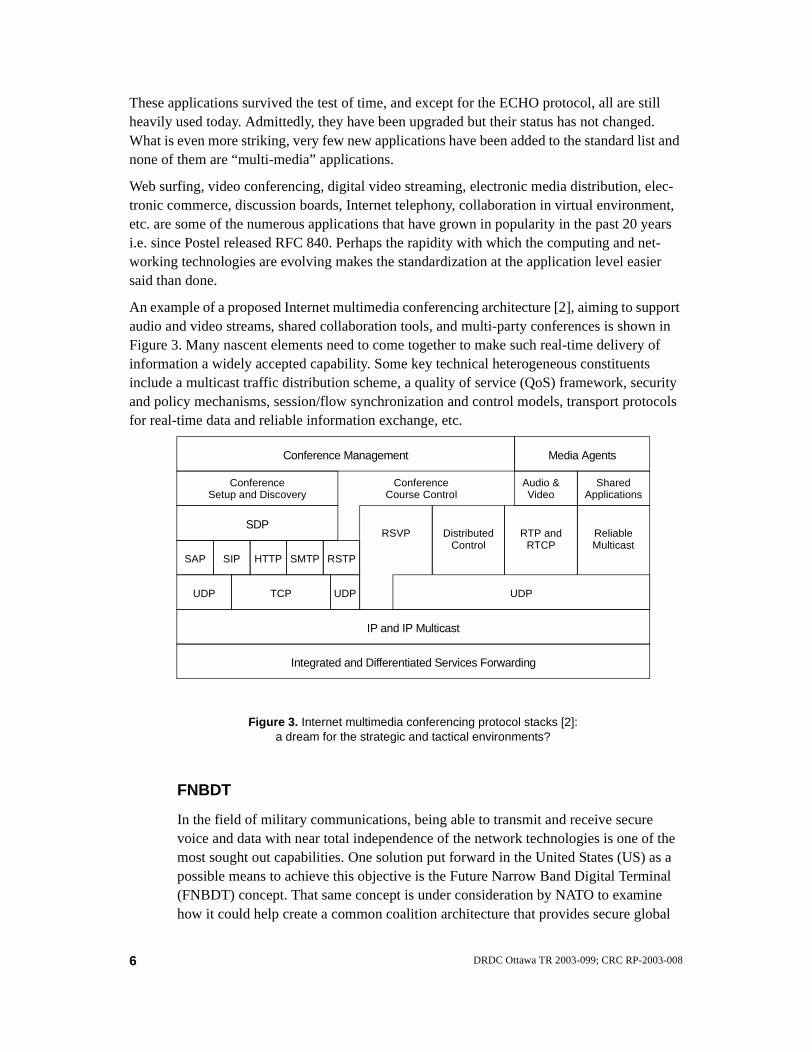
An example of a proposed Internet multimedia conferencing architecture [2], aiming to support audio and video streams, shared collaboration tools, and multi-party conferences is shown in Figure 3. Many nascent elements need to come together to make such real-time delivery of information a widely accepted capability. Some key technical heterogeneous constituents include a multicast traffic distribution scheme, a quality of service (QoS) framework, security and policy mechanisms, session/flow synchronization and control models, transport protocols for real-time data and reliable information exchange, etc.
FNBDT
In the field of military communications, being able to transmit and receive secure voice and data with near total independence of the network technologies is one of the most sought out capabilities. One solution put forward in the United States (US) as a possible means to achieve this objective is the Future Narrow Band Digital Terminal (FNBDT) concept. That same concept is under consideration by NATO to examine how it could help create a common coalition architecture that provides secure global
Figure 3. Internet multimedia conferencing protocol stacks [2]: a dream for the strategic and tactical environments?
RSVP
ConferenceCourse Control
SAP SIP HTTP SMTP RSTP
UDP UDPTCP
DistributedControl
RTP andRTCP
ReliableMulticast
UDP
ConferenceSetup and Discovery
SDP
IP and IP Multicast
Conference Management
SharedApplications
Audio &Video
Media Agents
Integrated and Differentiated Services Forwarding
6 DRDC Ottawa TR 2003-099; CRC RP-2003-008
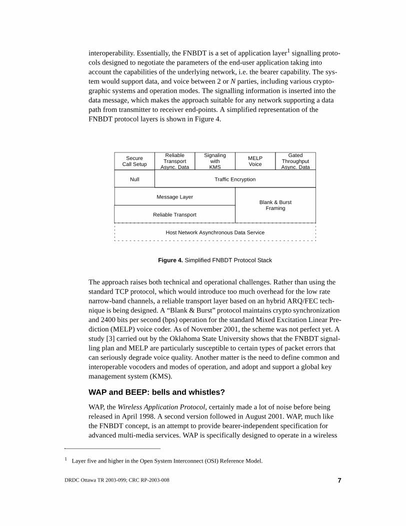
interoperability. Essentially, the FNBDT is a set of application layer1 signalling proto-cols designed to negotiate the parameters of the end-user application taking into account the capabilities of the underlying network, i.e. the bearer capability. The sys-tem would support data, and voice between 2 or N parties, including various crypto-graphic systems and operation modes. The signalling information is inserted into the data message, which makes the approach suitable for any network supporting a data path from transmitter to receiver end-points. A simplified representation of the FNBDT protocol layers is shown in Figure 4.
The approach raises both technical and operational challenges. Rather than using the standard TCP protocol, which would introduce too much overhead for the low rate narrow-band channels, a reliable transport layer based on an hybrid ARQ/FEC tech-nique is being designed. A “Blank & Burst” protocol maintains crypto synchronization and 2400 bits per second (bps) operation for the standard Mixed Excitation Linear Pre-diction (MELP) voice coder. As of November 2001, the scheme was not perfect yet. A study [3] carried out by the Oklahoma State University shows that the FNBDT signal-ling plan and MELP are particularly susceptible to certain types of packet errors that can seriously degrade voice quality. Another matter is the need to define common and interoperable vocoders and modes of operation, and adopt and support a global key management system (KMS).
WAP and BEEP: bells and whistles?
WAP, the Wireless Application Protocol, certainly made a lot of noise before being released in April 1998. A second version followed in August 2001. WAP, much like the FNBDT concept, is an attempt to provide bearer-independent specification for advanced multi-media services. WAP is specifically designed to operate in a wireless
1 Layer five and higher in the Open System Interconnect (OSI) Reference Model.
Secure
Message Layer
Call Setup
ReliableTransport
Async. Data
SignalingwithKMS
Reliable Transport
Host Network Asynchronous Data Service
Figure 4. Simplified FNBDT Protocol Stack
MELPVoice
GatedThroughputAsync. Data
Null Traffic Encryption
Blank & BurstFraming
7DRDC Ottawa TR 2003-099; CRC RP-2003-008
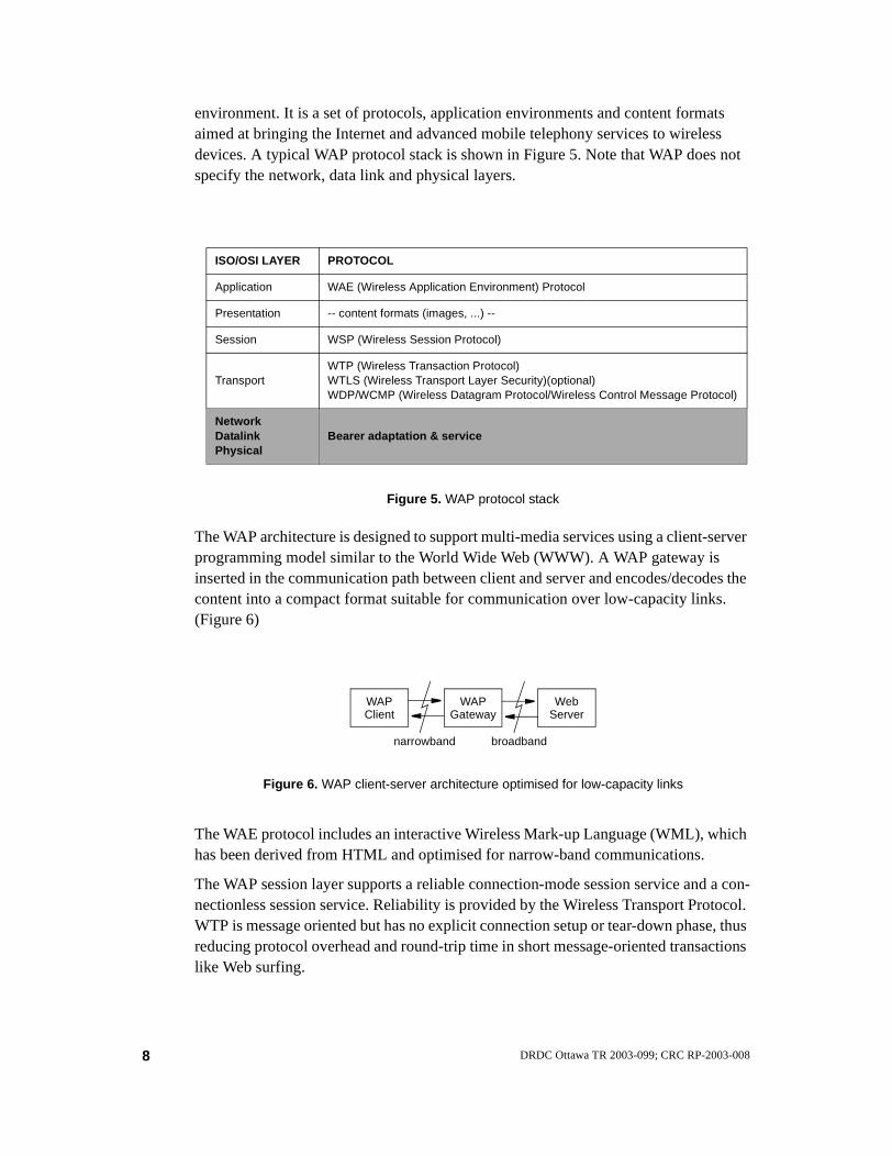
environment. It is a set of protocols, application environments and content formats aimed at bringing the Internet and advanced mobile telephony services to wireless devices. A typical WAP protocol stack is shown in Figure 5. Note that WAP does not specify the network, data link and physical layers.
The WAP architecture is designed to support multi-media services using a client-server programming model similar to the World Wide Web (WWW). A WAP gateway is inserted in the communication path between client and server and encodes/decodes the content into a compact format suitable for communication over low-capacity links. (Figure 6)
The WAE protocol includes an interactive Wireless Mark-up Language (WML), which has been derived from HTML and optimised for narrow-band communications.
The WAP session layer supports a reliable connection-mode session service and a con-nectionless session service. Reliability is provided by the Wireless Transport Protocol. WTP is message oriented but has no explicit connection setup or tear-down phase, thus reducing protocol overhead and round-trip time in short message-oriented transactions like Web surfing.
ISO/OSI LAYER PROTOCOL
Application WAE (Wireless Application Environment) Protocol
Presentation -- content formats (images, ...) --
Session WSP (Wireless Session Protocol)
TransportWTP (Wireless Transaction Protocol)WTLS (Wireless Transport Layer Security)(optional)WDP/WCMP (Wireless Datagram Protocol/Wireless Control Message Protocol)
NetworkDatalinkPhysical
Bearer adaptation & service
Figure 5. WAP protocol stack
WAPClient
WAPGateway
WebServer
Figure 6. WAP client-server architecture optimised for low-capacity links
narrowband broadband
8 DRDC Ottawa TR 2003-099; CRC RP-2003-008

End-to-end data integrity, privacy and authentication are provided by an optional secu-rity protocol, WTLS, similar to the Transport Layer Security protocol specified in RFC 2246 [4]. WTLS has been optimised for operation over long thin bearer networks.
Both WTP and WTLS run on top of the connectionless unreliable datagram service offered by Wireless Datagram Protocol. WDP hides the specificity of the underlying bearers and requires an adaptation to each bearer type. Interestingly, if the underlying bearer service uses IP, the WAP Forum specified that the WDP protocol should be the User Datagram Protocol (UDP).
A comparison of WTP and WDP with TCP and UDP was made by Taferner and Bonek in [5] and a summary is presented in Tables 2 and 3 respectively. It can be seen that WDP and UDP are nearly identical. Unlike TCP, WTP may not be adequate for trans-ferring large amounts of data. It has been optimised for short transactions. The lack of flow-control mechanisms in WTP could also be a problem in some networks.
If a lot of noise and hype surrounded WAP before its release, in comparison to WAP, BEEP appeared in no time at all. BEEP, the Blocks Extensible Exchange Protocol was
Table 2. Comparison of WAP and Internet protocols: WDP versus UDP
WDP UDP
For bearer service supporting IP
Both protocols are identical
For bearer service not supporting IP
Maximum packet length and packet header length may differ
Supports optional segmentation Doe not support segmentation
Supports optional error detection Checksum only
Table 3. Comparison of WAP and Internet protocols: WTP versus TCP
WTP TCP
Basic transmission unit Message-oriented Byte-stream-oriented
Connection set up & tear down phases
No such phases requiredoptimised for short connections with few data
3-way handshakeSuitable for long-lasting connections
Error detection Relies on WDP Built-in
Retransmission timer Not applicableAdjusted according to round-trip time
Protection against duplicates& out-of-order delivered packets
Each message uses a unique ‘Transaction ID’.
Each byte is numbered
Flow control
Only possible when optional segmentation is enabled.Uses a stop-and-wait mechanism.
Sophisticated sliding window with dynamical window adjustment
9DRDC Ottawa TR 2003-099; CRC RP-2003-008

specified in about a year, came out in March 2001 and is now a proposed standard [6] of the IETF. BEEP is not specifically designed for wireless or bandwidth-constrained applications. However, it does integrate the best practices for common, basic mecha-nisms that are needed when designing an application protocol over TCP. BEEP inte-grates the following optional building blocks into a single, coherent framework [7]:
• Framing messages
• Encoding data
• Negotiating capabilities (versions and options)
• Negotiating connection release
• Correlating requests and responses
• Handling multiple outstanding requests (pipelining)
• Handling multiple asynchronous requests (multiplexing)
• Providing integrated and modular security
These are common issues that arise time and time again and for which the wheel is continuously reinvented.
Message Exchange Service (MXS) in Iris
BEEP was not yet invented when MXS, a proprietary protocol, was developed for the Iris System. MXS provides multi-media services for many HIDS applications, such as Telephony and TMHS. MXS was designed to be light-weight and runs on top of TCP/UPD (Figure 7).
Iris Applications(NARS, HTP, PCP, DODB, HNS, etc.)
Figure 7. Placement of MXS in Iris protocol stack
Message Exchange Service(MXS)
Transmission ControlProtocol (TCP)
User DatagramProtocol (UDP)
Internet Protocol(IP)
HIDS Bearer Service(HBS)
PhysicalLink
UpperLayers
Layer 4Transport
Layer 3Network
Layer 2Data Link
Layer 1Physical
Stream Version 2Protocol (ST-II)
10 DRDC Ottawa TR 2003-099; CRC RP-2003-008

MXS defines a transaction-oriented interface called an exchange. An exchange exists between a client and a server. Because different clients require different services, sev-eral exchange kinds were developed, including:
• Unacknowledged Datagram Service, which provides a low overhead, connection-less service for short messages based on UDP. Messages are not guaranteed to be delivered; they may be received more than once; and they are not guaranteed to be received in the order they are transmitted.
• Acknowledged Datagram Service, which also provides a connectionless service for short messages based on UDP. There is no guarantee of message delivery but the service provides an application level acknowledgement of the message so that the client end is aware that the server did receive the message. This protocol sup-ports time-outs and retries since UDP does not provide those, as well as some per-sistence to overcome duplicates.
• Reliable Message Service, which relies on TCP to send messages and guarantee transmissions. It incorporates a “fast” keep-alive mechanism to catch dead connec-tions in a relatively short time.
Name Address Resolution Service (NARS) in Iris
Applications within the Iris System are identified by their names, but the network uses addresses to route information (data and voice) between the applications. NARS is a proprietary application that provides a service to resolve a user application name to the IP address of its affiliated network device interface in order for the users applications to be able to communicate with one another. The use of network addresses to support communications involving these names is transparent to the user.
Various types of names are used in Iris applications, including:
• O/R Names, which uniquely identifies a military formation, unit or subunit;
• NATO Deducible Directory (NDD) telephone numbers, in accordance with the for-mat defined by STANAG 5046;
• Allied Routing Prefix, which consists of a three-digit Nationality Identifier (NI) and a three-digit Area Code (AC), in accordance with STANAG 4214;
• Vehicle Names and LDN Site Names (a collection of vehicles interconnected by LDN links).
Application names within the Iris System are mobile in the sense that a particular user may reside at one location for a period of time and then move to another location.
NARS also follows a client-server model. Receivers register their address with the NARS Host server when they connect to a network and senders query the server for an address matching a target name. The Host server resides on the same LAN as the NARS client but Binding servers, which receive name/address binding updates from Host servers, are distributed throughout the network. A binding server where a particu-lar name/address binding is stored is determined via a hashing algorithm. The hashing function distributes bindings across all routers in the NARS domain evenly. Hence, the
11DRDC Ottawa TR 2003-099; CRC RP-2003-008

routing topological database is tightly coupled with the NARS functionality. Adding a new router to the network may cause existing NARS domain bindings to be dynami-cally redistributed. After changes in the network topology are learned and distributed by the routing protocol, updates are sent to add the binding to the new server and remove it from the old locations. The removal of a router from a network is treated in the same fashion.
SigComp
The Robust Header Compression (ROHC) Working Group of the IETF has defined a Signalling Compression (SigComp) interface (RFC 3320-3322), a solution for com-pressing messages generated by application protocols such as the Session Initiation Protocol (SIP) (RFC 3261) and the Real Time Streaming Protocol (RTSP) (RFC 2326). SigComp is offered to applications as a layer between the application and an underlying transport. The service provided is that of the underlying transport plus compression. SigComp supports a wide range of transports including TCP, UDP and the Stream Control Transmission Protocol (SCTP)(RFC 2960).
Operational characteristics
One very condensed description of the various traffic types to be handled by a network is pre-sented by the European Telecommunications Standards Institute (ETSI) in [8]. The document identifies the following four main traffic categories:
1. messages, are usually small (e.g. contained in one single packet or frame), must always be delivered, in order and error free. Latency is guaranteed to be within certain protocol defined limits, i.e. before time-out.
2. files, are transported from a buffer in one place to a buffer in another place. Unless a file is very large, latency and bit rate are not an issue.
3. non-interactive real-time stream, and
4. interactive real-time stream. Real-time flows need not be error free. Minor bit losses can usually be tolerated by human beings.
Another pragmatic way of dealing with the categorisation of network applications is presented by Rose et al. in RFC 3340 [9]. The approach broadly distinguishes applications by five opera-tional characteristics. These are:
• server push or client pull;
• synchronous (interactive) or asynchronous (batch);
• time-assured or time-insensitive;
• best-effort or reliable; and,
• stateful or stateless.
For example, the world-wide web is a pull, synchronous, time-insensitive, reliable, stateless service; whilst Internet mail is a push, asynchronous, time-insensitive, best-effort, stateless ser-vice.
12 DRDC Ottawa TR 2003-099; CRC RP-2003-008

An informational document of the Internet2 QoS Working Group states that there is an acute lack of understanding of the network performance that applications really require [10]. In [11], the group brings up the fact that it is not feasible to define a taxonomy of advanced applications on a single dimension and therefore, an attempt is made to define a taxonomy that spans sev-eral planes based on the task characteristics, type of media involved, the situation of operation (e.g., geographical sparsity of users) and the behavioural characteristics of the users (e.g., user expectations, user skills, etc.). A selected section of this multi-dimensional taxonomy, group-ing applications into several categories, is summarised in Figure 8.
Tactical multi-media applications involve both real-time and elastic traffic sources. The latter are applications that can always wait for data to arrive, for example:
• asynchronous bulk applications, such as e-mail and voice mail, have latency and through-put requirements that are very relaxed;
• interactive burst applications, such as telnet or Network File System (NFS) traffic, can tol-erate latencies in the order of a few hundreds of milliseconds;
• interactive bulk applications, like file (FTP) and web (HTTP) transfers, have latency requirements similar to the interactive burst applications but often demand a high through-put because of the large volume of data that may be involved.
Real-time (inelastic) applications, like voice and video, generate data streams that are highly time-dependent. Some will tolerate a wider range of variations in latency, throughput, or error than others. Adaptive applications try to adapt their resource demands within a range of accept-able values. Finally, an application is said to be intolerant if it fails to accomplish its task suffi-ciently or its QoS demands are not met.
Figure 8. Taxonomy of applications
Applications
Elastic
Intolerant
Real-time
Tolerant InteractiveBurst
InteractiveBulk
AsynchronousBulk
Adaptive Non-adaptive Rate-adaptive Non-adaptive
Rate-adaptiveDelay-adaptive
13DRDC Ottawa TR 2003-099; CRC RP-2003-008
Service models
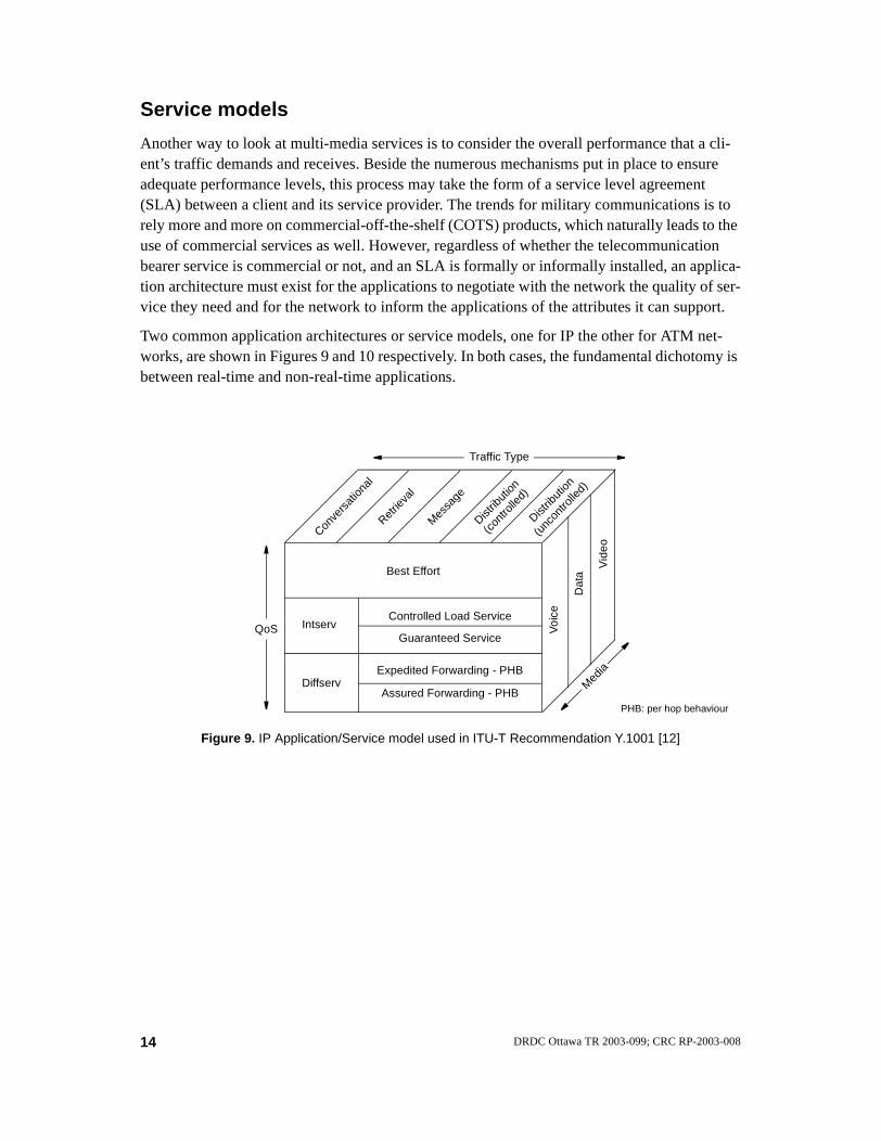
Another way to look at multi-media services is to consider the overall performance that a cli-ent’s traffic demands and receives. Beside the numerous mechanisms put in place to ensure adequate performance levels, this process may take the form of a service level agreement (SLA) between a client and its service provider. The trends for military communications is to rely more and more on commercial-off-the-shelf (COTS) products, which naturally leads to the use of commercial services as well. However, regardless of whether the telecommunication bearer service is commercial or not, and an SLA is formally or informally installed, an applica-tion architecture must exist for the applications to negotiate with the network the quality of ser-vice they need and for the network to inform the applications of the attributes it can support.
Two common application architectures or service models, one for IP the other for ATM net-works, are shown in Figures 9 and 10 respectively. In both cases, the fundamental dichotomy is between real-time and non-real-time applications.
Conve
rsat
ional
Retrie
val
Mes
sage
Distrib
ution
(con
trolle
d)
Distrib
ution
(unc
ontro
lled)
QoS
Vid
eo
Dat
a
Voi
ce
Diffserv
IntservGuaranteed Service
Controlled Load Service
Best Effort
Med
ia
Traffic Type
Assured Forwarding - PHB
Expedited Forwarding - PHB
PHB: per hop behaviour
Figure 9. IP Application/Service model used in ITU-T Recommendation Y.1001 [12]
14 DRDC Ottawa TR 2003-099; CRC RP-2003-008

In a military heterogeneous environment, hybrid QoS architectures are possible and likely. A concept that has been proposed for the Internet in the last few years is to combine both IntServ and DiffServ in the same architecture for end-to-end service provision [14]. Hybrid QoS archi-tectures require a mapping of the QoS services from one model to another (Figure 11).
To illustrate the point, consider IntServ and ATM, the two most popular models used in the mid 90’s. One possible map-ping is as follows [15]: the IntServ Guaranteed service can be mapped eas-ily into CBR or rt-VBR; the Controlled Load service into nrt-VBR and ABR; and best effort service into ABR and UBR. Other similar guidelines are pro-vided in RFC 2381 [16].
Figure 10. ATM Application/Service model specified by the ATM Forum [13]
Service Categories
r.t. VBRAllows statistical multiplexing;
Real-time Non-real-time
CBRFixed, guaranteed resources
UBRBest effort, no explicit network control orsource description; rate adaptation and lossrecovery at end point
n.r.t. VBRAdds explicit resource reservation;
ABRUses feedback to
takes advantage of limited tolerance to loss(includes peak-allocated VBR as special case)
improves loss and delay improve loss and fairness
Acronyms: r.t. Real-Time; n.r.t. Non-Real-Time; CBR Constant Bit Rate; VBR Variable Bit Rate; UBR Unspecified Bit Rate; ABR Available Bit Rate
ATM
IntServ DiffServ
Figure 11. Hybrid architectures require QoS mapping between different service models
15DRDC Ottawa TR 2003-099; CRC RP-2003-008

End-user services in Iris
The Iris Communication System provides several basic services to its users, including voice communication, electronic messaging and facsimile transmission services. A summary of the service characteristics is given in Table 4. Some telephony functions include, call routing, call precedence and preemption, conference and broadcast calls, switched hot-lines, call tracing and other calling features like call forward, call hold, call transfer, call pending, etc.
2. Transmission environments
The digitized battlefield expects a lot from modern communications systems. Networking and internetworking are not possible without establishing physical connections between nodes. These links have properties that impact the quality of service available to communicate, which creates an interdependency between the various protocol layers. This section briefly discusses three of the most important types of impairment. An overview of the Iris tactical bearers is pro-vided as an example of a tactical IP environment.
IP packet radio: a very long catThe wireless telegraph is not difficult to understand. The ordinary telegraph is like a very long cat. You pull the tail in New York, and it miaows in Los Angeles. The wireless is the same, only without the cat. — Albert Einstein [17]
Communication links have several unique characteristics but three of them are particularly important. Wireless transmission links are:
• prone to errors;
• limited in capacity; and,
• delayed in time.
These impediments vary in importance according to the type of link considered but in general all radio links suffer to some extent from these same constraints.
Table 4. Basic end-user services in Iris
SERVICE APPLICATION CHARACTERISTICS
Voice
Intra-vehicule Crew IntercomPCM, 128 kbps, full duplexOperates over the vehicule’s LAN
Inter-vehicule Staff IntercomCVSD, 16 kbps, half duplexOperates over the Link Distribution Network interconnecting vehicules
TelephonyCVSD?, 2x16 kbps, full duplexOperates over the vehicule’s LAN and Trunk Distribution Network
Messaging Tactical Message Handling System Secure, reliable, X.400-based
16 DRDC Ottawa TR 2003-099; CRC RP-2003-008
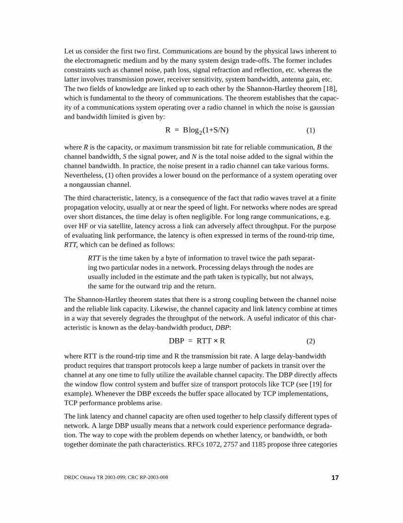
Let us consider the first two first. Communications are bound by the physical laws inherent to the electromagnetic medium and by the many system design trade-offs. The former includes constraints such as channel noise, path loss, signal refraction and reflection, etc. whereas the latter involves transmission power, receiver sensitivity, system bandwidth, antenna gain, etc. The two fields of knowledge are linked up to each other by the Shannon-Hartley theorem [18], which is fundamental to the theory of communications. The theorem establishes that the capac-ity of a communications system operating over a radio channel in which the noise is gaussian and bandwidth limited is given by:
(1)
where R is the capacity, or maximum transmission bit rate for reliable communication, B the channel bandwidth, S the signal power, and N is the total noise added to the signal within the channel bandwidth. In practice, the noise present in a radio channel can take various forms. Nevertheless, (1) often provides a lower bound on the performance of a system operating over a nongaussian channel.
The third characteristic, latency, is a consequence of the fact that radio waves travel at a finite propagation velocity, usually at or near the speed of light. For networks where nodes are spread over short distances, the time delay is often negligible. For long range communications, e.g. over HF or via satellite, latency across a link can adversely affect throughput. For the purpose of evaluating link performance, the latency is often expressed in terms of the round-trip time, RTT, which can be defined as follows:
RTT is the time taken by a byte of information to travel twice the path separat-ing two particular nodes in a network. Processing delays through the nodes are usually included in the estimate and the path taken is typically, but not always, the same for the outward trip and the return.
The Shannon-Hartley theorem states that there is a strong coupling between the channel noise and the reliable link capacity. Likewise, the channel capacity and link latency combine at times in a way that severely degrades the throughput of the network. A useful indicator of this char-acteristic is known as the delay-bandwidth product, DBP:
(2)
where RTT is the round-trip time and R the transmission bit rate. A large delay-bandwidth product requires that transport protocols keep a large number of packets in transit over the channel at any one time to fully utilize the available channel capacity. The DBP directly affects the window flow control system and buffer size of transport protocols like TCP (see [19] for example). Whenever the DBP exceeds the buffer space allocated by TCP implementations, TCP performance problems arise.
The link latency and channel capacity are often used together to help classify different types of network. A large DBP usually means that a network could experience performance degrada-tion. The way to cope with the problem depends on whether latency, or bandwidth, or both together dominate the path characteristics. RFCs 1072, 2757 and 1185 propose three categories
R Blog2(1+S/N)=
DBP RTT R×=
17DRDC Ottawa TR 2003-099; CRC RP-2003-008
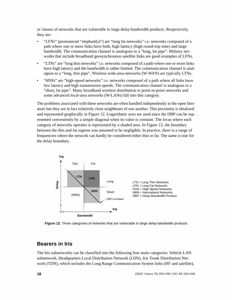
or classes of networks that are vulnerable to large delay-bandwidth products. Respectively, they are:
• “LFNs” (pronounced “elephant(s)”) are “long fat networks” i.e. networks composed of a path where one or more links have both, high latency (high round-trip time) and large bandwidth. The communication channel is analogous to a “long, fat pipe”. Military net-works that include broadband geosynchronous satellite links are good examples of LFNs.
• “LTNs” are “long thin networks” i.e. networks composed of a path where one or more links have high latency and the bandwidth is rather limited. The communication channel is anal-ogous to a “long, thin pipe”. Wireless wide-area-networks (W-WAN) are typically LTNs.
• “HSNs” are “high-speed networks” i.e. networks composed of a path where all links have low latency and high transmission speeds. The communication channel is analogous to a “short, fat pipe”. Many broadband wireless distribution or point-to-point networks and some advanced local-area networks (W-LANs) fall into this category.
The problems associated with these networks are often handled independently in the open liter-ature but they are in fact relatively close neighbours of one another. This proximity is idealized and represented graphically in Figure 12. Logarithmic axes are used since the DBP can be rep-resented conveniently by a simple diagonal when its value is constant. The locus where each category of networks operates is represented by a shaded area. In Figure 12, the boundary between the thin and fat regions was assumed to be negligible. In practice, there is a range of frequencies where the network can hardly be considered either thin or fat. The same is true for the delay boundary.
Bearers in Iris
The Iris subnetworks can be classified into the following four main categories: Vehicle LAN subnetwork, Headquarters Local Distribution Network (LDN), Iris Trunk Distribution Net-work (TDN), which includes the Long Range Communication System links (HF and satellite),
LTN LFN
HSN
Bandwidth
log
log
Del
ay
Figure 12. Three categories of networks that are vulnerable to large delay-bandwidth products
DBP=constant
LTN = Long Thin NetworksLFN = Long Fat NetworksHSN = High Speed NetworksNBN = Narrowband Networks
Thin Fat
Long
ShortDBP = Delay-Bandwidth Product(NBN)
18 DRDC Ottawa TR 2003-099; CRC RP-2003-008

and CNR subnetwork. There are several other types of subnetworks that are used to establish connectivity between the Iris System and other communication systems: the Allied digital trunk network, the Allied STANAG 5040 network, the Commercial and military single channel networks, and the Strategic Messaging networks. These will not be considered further here.
Commonality of the LAN/LDN/TDN Protocols
There is an important element unifying the LAN, LDN and TDN subnetworks - the use of a same link layer packet format and virtual circuit switching scheme as specified by a proprietary HIDS Bearer Service (HBS) protocol (Figure 7). HBS employs small packets having a length of 80 to 255 bytes. Every HBS packet has a small header iden-tifying the virtual circuit (VC) to which it belongs. This approach allows end-to-end VCs to be set up across the LAN/LDN/TDN Internet. HBS is in many aspects similar to the ATM switching technology.
Vehicle Local Area Network
The LAN consists of one or more hosts connected in a point-to-point fashion by bi-directional serial links. The LAN topology is generally fixed and is either a ring con-figuration or a two daisy-chain configuration. Connections to the LAN are established between hosts using copper cables. Each LAN link supports the equivalent of 120 duplex streams at 16 kbps each way.
The LAN physical and data link layers are implemented using the High-Level Data Link Control (HDLC) protocol. The HDLC frames are sent asynchronously to allow for end-to-end frame synchronization. The raw bit rate on the LAN is 4 Mbps.
Local Distribution Network
User and Control traffic is transferred between vehicles through the LDN, which is based on a connect-anywhere, connect-any-time mesh architecture. LDN connections are established between vehicles using LDN fibre optic cables. Any LDN port may be connected to any other LDN port of the same transmission rate. Each LDN link pro-vides the bandwidth to support the equivalent of 480 unidirectional streams at 16 kbps each.
The LDN physical and data link layers are based on HDLC links. LDN links operate at 6.2 Mbps with encoding. The raw line bit rate is 8 Mbps.
Iris Trunk Network
The Iris Trunk Distribution Network (TDN) is used to exchange traffic between head-quarters, vehicles and installations using long-distance point-to-point links. The TDN is composed of the following link types: fibre-optic cable links, Band I, IV or V Line Of Sight Radio Relay (LOS-RR) links and SATCOM links.
Traffic on each trunk link is encrypted using a standard KG-194A EUROCOM trunk encryption device. A trunk link can be configured by network management commands
19DRDC Ottawa TR 2003-099; CRC RP-2003-008

to operate at any of the following bandwidths: 256, 512, 1024 or 2048 kbps (not avail-able for SATCOM links). An option was to upgrade the trunk capacity to 8-16 Mbps.
The TDN supports the same set of protocols as the one used on the LDN with the addi-tion of Forward Error Correction (FEC) and Time Dispersion Coding (TDC) sub-lay-ers. It is possible to disable FEC (Reed-Solomon coding) and TDC (bit interleaving)
on the links where the BER is better than 1 in 106. This improves the link traffic throughput. Normally, FEC and TDC are always used over LOS-RR links but not on fibre optic links. FEC and TDC can be turned on/off on SATCOM links.
The use of TDC improves the burst error rate performance of the TDN links. FEC block frames are bit interleaved to spread burst errors over several blocks, allowing the FEC more opportunity to detect and correct errors. The interleaving length factor depends upon the bandwidth selected and varies between 1 and 4. It is possible to turn interleaving off on links not subject to burst errors so as to reduce transmission delay.
CNR Subnetwork
The CNR subnetwork is a half-duplex net of all-informed (i.e. broadcast) communica-tions which take place on a single radio channel in the VHF, UHF or HF band. Trans-missions may be on a single-frequency or frequency-hopped and either secure or non-secure.
CNR radio nets can operate in one of several modes: voice only, data only, or mixed voice and data. Depending of the radio types and configurations, CNR radios can sup-port several traffic types: digital voice, analogue voice, digital data, and analogue data.
Because of the low throughput and high error rate, CNR nets are inappropriate to carry the standard set of traffic protocols used over the LAN/LDN/TDN subnetworks. For these reasons, CNR nets provide a different set of services to Iris System users.
Users in the backbone network (HIDS) must subscribe to a radio gateway to monitor the CNR Net in voice mode. Packet streams are established between the end-users and the Transmit/Receive Radio Interface(s) in the backbone network where the net is under surveillance by one or more designated stations. For digital voice nets, each stream reserves 16 kbps bandwidth. For analogue voice nets, each stream reserves a 32 kbps bandwidth.
A similar registration mechanism is used to provide the TMHS data delivery services. Stations (hosts) must register/deregister with the CNR-Net’s Radio Interface when they wish to transmit/receive messages via the net. Every net can have up to 15 radios subscribed to it at a time.
The radio gateway makes use of a proprietary Radio Data Link (RDL) protocol, which operates in three basic modes: voice-only, data-only, or mixed voice/data.
RDL operates in a peer-to-peer fashion, arbitrating both voice and data traffic simulta-neously in mixed mode on the same transmission medium using a p-persistent Carrier
20 DRDC Ottawa TR 2003-099; CRC RP-2003-008

Sense Multiple Access (CSMA) protocol. The RDL allows broadcast, multicast or uni-cast datagram message delivery.
RDL is a voice-over-data protocol. In mixed voice and data mode, Information frames (containing user data) and Supervisory frames (containing acknowledgment data) are punctuated at periodic intervals with Voice Access Pauses (VAPs). The VAPs give radio users access to the medium without disrupting data transmissions already in progress. Once voice access has been granted, the user has unlimited continuous access to the net.
RDL ensures data integrity via Time Dispersion Coding (TDC), Majority Vote Detec-tion (MVD), Golay Forward Error Correction (FEC) encoding and Frame Check Sequence (FCS). TDC is effective in dealing with burst noises. Golay allows data vali-dation at the receiving end by adding parity bits to data bits. The combined effect of
MVD, TDC and FEC is to reduce a raw bit error rate of 10-2 to a residual 10-5. The FCS allows for the detection of uncorrected bit errors.
3. IP-based integration
This section has three main threads:
1. The first thread is about IP in general and the fact that it is a packet switching technology offering a best effort service. It presents a high level view of the difficulties for IP to sup-port QoS-based services.
2. The second thread is entitled “Making IP work in problematic environments”. This section discusses several options for coping with the three basic problems mentioned in Section 2.: bandwidth constraint, error and delay impairments.
3. The last thread highlights the QoS aspects of the Iris System.
Is IP a new religion?
The success of the Internet is so incredible that it is hard to find a soul today who has not heard about IP. The initial four-node ARPANET research project has become a planetary distributed network joined by devotees from all origins. From a technical point of view, it is not clear if the driving force behind this phenomena can be attributed solely to intellectual challenges and sci-entific curiosity. One might suspect that part of the conversion to IP is now driven by money, fame and politics. Otherwise, looking at the many difficulties of making IP support graded ser-vices, it takes faith to believe that IP is the best technical solution in all circumstances.
As of April 2003, the IETF’s list of standards-related publications includes:
• 62 standards;
• 74 draft standards;
21DRDC Ottawa TR 2003-099; CRC RP-2003-008

• 739 proposed standards;
• 1916 Internet Drafts in progress; about three fifth of them (1121) are individual submis-sions, the others originate from 130 different working groups. The IETF registers 338 workings groups, 133 are active and 205 are concluded. Unrevised drafts have a maximum life time of six months;
• 163 experimental RFCs;
• 71 Best Current Practice RFCs.
This is an impressive amount of technical specifications and much work in progress. Is the Internet so complex? Hum, IP itself is relatively simple and in fact, there lies its power. Could it be that the bulk of this literature is produced because people find it more interesting to do research on something new than to put real working systems out in the field? It is doubtful, and besides, one should not be misanthrope. Then what? One possible explanation is that the trend nowadays is to try to transform the Internet architecture into something that is intrinsically opposed to the original concepts and design principles the Internet is based upon. This theme cannot be developed further in the space available but the reader should be able to find several examples of this “kink” spread throughout this document.
IP rules!
From a military standpoint, the three best things about IP are probably its universality, its relative robustness/survivability, and its simplicity. These characteristics are built-in i.e. they were part of the initial design goals when the DARPA-Internet (ARPANET) was first conceived.
• Universality — IP has become the lowest common denominator among networks by providing global network-layer connectivity. It offers a universal (IP) connec-tivity service to all machines that have an IP address. IP has the ability to connect together in a seamless way not only multiple nodes but multiple networks of diverse architectures. This internetworking and interoperability capability —two great buzzwords heavily used in the network world today— allow full “open sys-tem interconnection” for data exchange and communication across diverse trans-mission paths.
• Robustness and Survivability — IP-based networks do not have Byzantine robust-ness but still outclass most connection oriented networks. This is because IP rout-ers are designed to be stateless. They forward each IP datagram independently of other datagrams. As a result, redundant paths can be exploited to provide robust service in spite of failures of intervening routers and networks. A network will therefore recover gracefully from a whole range of exceptional situations in a given environment. For instance, IP networks can survive the loss or failure of subnet hardware like routers and hosts, and recover existing data exchange or even maintain conversations using whatever bandwidth is still available. The TCP/IP protocol suite can tolerate wide network variation and a wide range of network characteristics e.g. bandwidth, delay, packet loss, packet reordering, and maximum packet size.
22 DRDC Ottawa TR 2003-099; CRC RP-2003-008

• Simplicity — This characteristic is a two-edged sword. As a best-effort connec-tionless network, IP rules! Use of datagrams between intermediate nodes allows relatively simple protocols at this level. If stringent levels of service must be guar-anteed then the original IP design philosophy gets in the way, raising numerous challenging design issues and much complexity.
IP’s Achilles’ heel
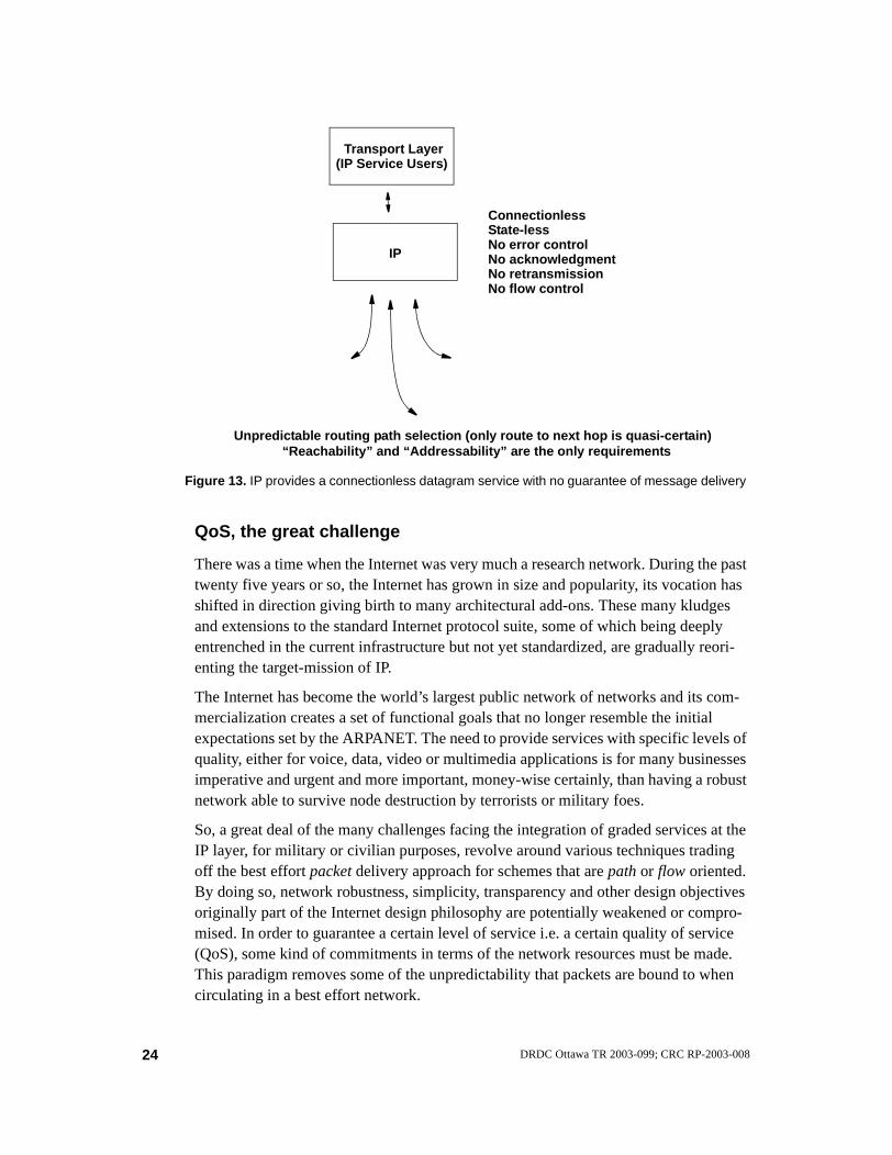
IP’s greatest characteristic is also its Achilles’ heel: a simple connectionless service with a no better than best-effort quality of service (QoS) guarantee. IP does not provide a reliable communication service. There are no acknowledgments either end-to-end or hop-by-hop. There is no error control for data, only a header checksum. There are no retransmissions. There is no flow control. The modern notion of QoS cannot be suc-cessfully applied to IP unless extensive support is built around IP to guarantee access to requisite resources and thus achieve the desired performance. IP by itself uses four mechanisms in providing its datagram service:
• Type of Service1 (ToS),
• Time to Live (TTL),
• Options, and
• Header Checksum.
These are insufficient to fulfil the many requirements of the applications and manage fairly the network resources.
As illustrated in Figure 13, IP’s simplicity lies in providing a connectionless service. The classic IP approach does not make use of expansive support mechanisms to pro-vide a service level, that may need to be saved from extinction someday.
1 The Differentiated Services standard redefines the existing IP ToS field to indicate forwarding behaviors.
23DRDC Ottawa TR 2003-099; CRC RP-2003-008
QoS, the great challenge
There was a time when the Internet was very much a research network. During the past twenty five years or so, the Internet has grown in size and popularity, its vocation has shifted in direction giving birth to many architectural add-ons. These many kludges and extensions to the standard Internet protocol suite, some of which being deeply entrenched in the current infrastructure but not yet standardized, are gradually reori-enting the target-mission of IP.
The Internet has become the world’s largest public network of networks and its com-mercialization creates a set of functional goals that no longer resemble the initial expectations set by the ARPANET. The need to provide services with specific levels of quality, either for voice, data, video or multimedia applications is for many businesses imperative and urgent and more important, money-wise certainly, than having a robust network able to survive node destruction by terrorists or military foes.
So, a great deal of the many challenges facing the integration of graded services at the IP layer, for military or civilian purposes, revolve around various techniques trading off the best effort packet delivery approach for schemes that are path or flow oriented. By doing so, network robustness, simplicity, transparency and other design objectives originally part of the Internet design philosophy are potentially weakened or compro-mised. In order to guarantee a certain level of service i.e. a certain quality of service (QoS), some kind of commitments in terms of the network resources must be made. This paradigm removes some of the unpredictability that packets are bound to when circulating in a best effort network.
Transport Layer
IP
ConnectionlessState-less
Unpredictable routing path selection (only route to next hop is quasi-certain)
No error controlNo acknowledgmentNo retransmission
Figure 13. IP provides a connectionless datagram service with no guarantee of message delivery
“Reachability” and “Addressability” are the only requirements
No flow control
(IP Service Users)
24 DRDC Ottawa TR 2003-099; CRC RP-2003-008

Deciding the placement in the network of elements able to support IP for achieving a given service level has been and continues to be a foremost active research topic in IP networking. So far, many solutions and technologies have been developed and the sci-entific community has made great progress in understanding what is feasible or achievable in this area. Nevertheless, there still is no consensus on what is the best solution to this complex problem. QoS provisioning architectures are deployed in local area networks and other relatively small networks but there is no wide-spread end-to-end deployment of QoS services in the Internet.
Notwithstanding the economic and political issues, one of the sensible reasons that can explain this slow progress is complexity — the problem and its solution involve the interaction of several mechanisms, not only QoS control mechanisms operating in a best-effort environment but other control mechanisms needed to fulfil and manage diverse requirements at both the user and network levels. These include performance, reliability, security, availability, policy, etc.
A total reversal of the Internet philosophy
“What sort of changes would be helpful in next generation networks? Of course higher data rates and lower cost are desirable, but of all parameters, I
would opt for greater emphasis on robustness.” - Paul Baran, 19771
At the moment, the most weighty element among the top lead proposals to help build QoS support on the Internet is IPv6. Of course, IPv6 addresses many other foreground issues (IP address pool refill, routing table size reduction, better security mechanism, etc.) aimed at sustaining the long term growth of the Internet, which make it even more important. IPv6’s approach redefines IPv4’s packet header (see Table 5) and offers the possibility of turning what was once a simple datagram switching network into a more complex switched virtual circuit network. It defines traffic class and flow label fields that routers can examine to allocate resources and manage traffic flows with service guarantees.
IPv6 is a draft standard of the IETF and opens the door to a radical change of the Inter-net. With a flow label field built into every IP packet it should, in principle, become easier and apropos to establish virtual circuits and set up connection-oriented services through the Internet backbone. This is a radical departure from the original concept that has always characterised the traditional IP network architecture: the simple con-nectionless datagram approach. Of course, inasmuch as the Internet Service Providers will allow it, it should still be possible to operate IP-based networks in the connection-less mode by disregarding the Flow label field. Neither does it mean that if flows must be established then such networks cannot be designed with stateless cores. There are advanced QoS control mechanisms that make the latter possible but still, with IPv6, service provisioning based on a virtual circuit approach is making inroads into the land of connectionless IP.
1 Some perspectives on networks —Past, Present and Future. Information Processing 77, North-Holland Publish-ing Company, 1977
25DRDC Ottawa TR 2003-099; CRC RP-2003-008

ATM 5, IPv4 20, IPv6 40!
For narrow-band systems, where header overhead is of concern, the two and a half bytes of the Flow label field that must be carried in every IPv6 datagram will consti-tute, more often than not, a burden. In fact, two and a half bytes may not sound like a lot but this overhead represents 50% of the size of a standard ATM cell header alone. IPv4 packets have a typical IP header of 20 bytes whereas in IPv6, the IP header is 40 bytes long. Comparison of the header size in IP and ATM is shown in Figure 14.
In the IP versus ATM debate, it is generally stated that compared to IP ATM carries a price:
1. in terms of loss of throughput, due to ATM overhead, and,
2. in terms of ATM network management.
In the context of wireless narrow-band QoS-enabled networks, these two arguments must be weighted carefully. For transporting real-time information such as voice, the payload is small and the combined RTP/UDP/IP headers represent higher overhead than the ATM header. This forces the use of header compression in IP-based networks. For transporting data, the presence of errors in the wireless channel considerably limits the maximum size of the link layer frames, and consequently, the advantage in throughput obtainable with IP is also quite reduced. On the second issue, mechanisms
Table 5. IP’s built-in mechanisms for supporting QoS
MECHANISM IPv4 IPv6
Classes of service Type of servicea (ToS)
a Now redefined and renamed the Differentiated Services (DS) field.
Traffic class
Pseudo-connection (resource reservation) - Flow label
Error detection Header checksum -
Packet lifetime Time to live (TTL) Hop limit
OptionsSource routingSecurity
Source routingSecurity
ATM IPv4 IPv6
5
20
40
Figure 14. Header overhead in ATM, IPv4, IPv6
Bytes
Hea
der
Siz
e
26 DRDC Ottawa TR 2003-099; CRC RP-2003-008

for providing QoS at the transport and network layers have been studied within the Internet for many years and shown to be more challenging than originally thought. So far there has been limited deployment of network QoS mechanisms for IP and the net-working community is still debating whether the proposed solutions deliver a high enough performance to price ratio. For the time being, it looks as if ATM retains its market niche, carrying a price tag that is above that promised for IP but with service guarantees that IP has yet to deliver. MPLS appears to find a similar niche for support-ing traffic engineering. There is no clear indication that IP will in the next five years widely replace ATM (or MPLS) in QoS-enabled networks.
Are virtual circuits bad for tactical networks?
Armies and wars have changed quite a bit over the last century. Requirements for tacti-cal information exchange on the battlefield or throughout the chain of command con-ceal a wide range of technical issues. These must be addressed most often in the context of diametrically opposed constraints. Technical advances open up new oppor-tunities that need to be exploited but it would be unwise to constantly migrate the defence communications infrastructure to the latest fashionable technology without ensuring, mainly by diversification of system concepts, a minimum of diversified com-munications alternatives. This is reinforced by the fact that even though choosing one technology over another is difficult, different technologies often have complementary characteristics that are much needed.
In the field of communications technology, the risk of obsolescence is phenomenal. The case of the newly fielded Iris Tactical Communication System for the Canadian Army is revealing. Iris provides bearers with virtual-circuit switching capability based on IPv5 and a packet switching technology in many aspects similar to ATM. It may be paradoxical but there is an example of a much appraised state-of-the-art system based on two technologies that were highly popular at one time but have faded considerably in recent years.
In the case of ATM, it is often said that it lost the battle of the desktop to IP primarily because of its complexity. Perhaps what is too complex for the commercial world is still manageable in a military environment. In Iris, end-users can setup end-to-end vir-tual circuits inside any vehicle’s LAN internet or across vehicles and to remote head-quarters through the local and trunk distribution networks. Simplicity of the link-layer switching fabric in Iris, as in the ATM case, requires the use of complex mechanisms and control plane protocols to establish and manage these virtual circuits.
As for IPv5, if one recalls (see Table 6 and the modified version in Figure 15 of the well known hourglass model of the Internet architecture), it was an experimental data stream protocol that served as an adjunct to, not a replacement for, connectionless best-effort IPv4 communications. Also named ST-II, the first version of this connection-ori-ented protocol had been developed at MIT Lincoln Laboratory in late 70’s to support the efficient delivery of real-time data streams to single or multiple destinations in applications that require guaranteed QoS. Today, it seems to have been abandoned for RSVP, which, by contrast, does not require its own IP version assignment.
27DRDC Ottawa TR 2003-099; CRC RP-2003-008
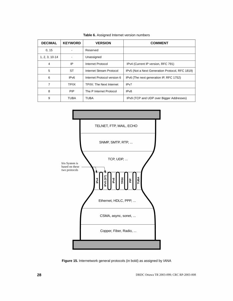
Table 6. Assigned Internet version numbers
DECIMAL KEYWORD VERSION COMMENT
0, 15 - Reserved
1, 2, 3, 10-14 - Unassigned
4 IP Internet Protocol IPv4 (Current IP version, RFC 791)
5 ST Internet Stream Protocol IPv5 (Not a Next Generation Protocol, RFC 1819)
6 IPv6 Internet Protocol version 6 IPv6 (The next generation IP, RFC 1752)
7 TP/IX TP/IX: The Next Internet IPv7
8 PIP The P Internet Protocol IPv8
9 TUBA TUBA IPv9 (TCP and UDP over Bigger Addresses)
IPv6
TU
BA
IPv5
(S
T)
TP
/IX
PIP
IPv4
Ethernet, HDLC, PPP, ...
Copper, Fiber, Radio, ...
CSMA, async, sonet, ...
TCP, UDP, ...
SNMP, SMTP, RTP, ...
TELNET, FTP, MAIL, ECHO
Figure 15. Internetwork general protocols (in bold) as assigned by IANA
Iris System isbased on thesetwo protocols
28 DRDC Ottawa TR 2003-099; CRC RP-2003-008
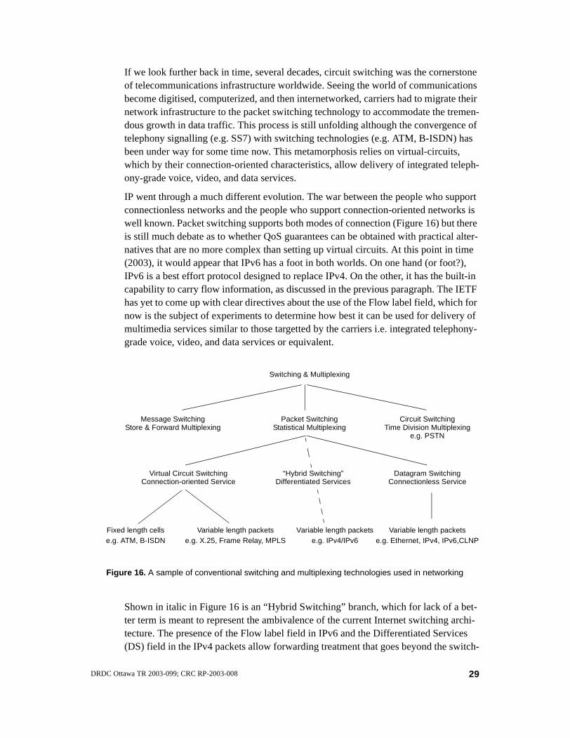
If we look further back in time, several decades, circuit switching was the cornerstone of telecommunications infrastructure worldwide. Seeing the world of communications become digitised, computerized, and then internetworked, carriers had to migrate their network infrastructure to the packet switching technology to accommodate the tremen-dous growth in data traffic. This process is still unfolding although the convergence of telephony signalling (e.g. SS7) with switching technologies (e.g. ATM, B-ISDN) has been under way for some time now. This metamorphosis relies on virtual-circuits, which by their connection-oriented characteristics, allow delivery of integrated teleph-ony-grade voice, video, and data services.
IP went through a much different evolution. The war between the people who support connectionless networks and the people who support connection-oriented networks is well known. Packet switching supports both modes of connection (Figure 16) but there is still much debate as to whether QoS guarantees can be obtained with practical alter-natives that are no more complex than setting up virtual circuits. At this point in time (2003), it would appear that IPv6 has a foot in both worlds. On one hand (or foot?), IPv6 is a best effort protocol designed to replace IPv4. On the other, it has the built-in capability to carry flow information, as discussed in the previous paragraph. The IETF has yet to come up with clear directives about the use of the Flow label field, which for now is the subject of experiments to determine how best it can be used for delivery of multimedia services similar to those targetted by the carriers i.e. integrated telephony-grade voice, video, and data services or equivalent.
Shown in italic in Figure 16 is an “Hybrid Switching” branch, which for lack of a bet-ter term is meant to represent the ambivalence of the current Internet switching archi-tecture. The presence of the Flow label field in IPv6 and the Differentiated Services (DS) field in the IPv4 packets allow forwarding treatment that goes beyond the switch-
Figure 16. A sample of conventional switching and multiplexing technologies used in networking
Switching & Multiplexing
Packet SwitchingStatistical Multiplexing
Circuit SwitchingTime Division Multiplexing
Message SwitchingStore & Forward Multiplexing
Fixed length cells Variable length packets
Datagram SwitchingConnectionless Service
Virtual Circuit SwitchingConnection-oriented Service
Variable length packetse.g. ATM, B-ISDN e.g. X.25, Frame Relay, MPLS e.g. Ethernet, IPv4, IPv6,CLNP
e.g. PSTN
“Hybrid Switching”Differentiated Services
Variable length packetse.g. IPv4/IPv6
29DRDC Ottawa TR 2003-099; CRC RP-2003-008

ing level provided by the best effort service. Still, this treatment so far favours flow aggregation as opposed to virtual circuit (VC) establishment, which the IETF tries to stay away from in its general philosophy.
The key reason for using virtual circuits in a tactical environment today is that VC-based networks offer QoS guarantees that datagram networks do not (Tables 7 and 8).
Table 7. Some factors influencing choice of switching technology
NETWORKTYPE
BANDWIDTH DELAY QOSGUARANTEE
COMPLEXITY
Message switching
needs minimal bandwidth to operate
provides long term data retention
does not support real-time applications
needs large storage capacity
Circuit switching
dedicated, fixed bandwidth
wasteful of bandwidth when traffic is bursty or circuit not in use
needs call setup high
conservative
easy admission/congestion control
Difficult to implement autonomous private networks
Datagram switching dynamic bandwidth
efficient use of bandwidth due to statistical multiplexing
packets may experience long delays and not arrive in order
low (best effort service)
reliability must be built into end-nodes
Virtual circuit switching
needs call setup
delay more variable than PVC or dedicated circuits
highrelies on core nodes to route through connections
Table 8. Comparison of datagram and virtual-circuit subnets [20]
ISSUE DATAGRAM SUBNET VIRTUAL-CIRCUIT SUBNET
Circuit setup Not needed Required
AddressingEach packet contains the full source and destination address
Each packet contains a short VC number
State informationRouters do not hold state information about conections
Each VC requires router table space per connection
Routing Each packet is routed independentlyRoute chosen when VC is set up; all packets follow it
Effect of router failuresNone, except for packets lost during the crash
All VCs that passed through the failed router are terminated
Quality of service DifficultEasy if enough resources can be allocated in advance for each VC
Congestion control DifficultEasy if enough resources can be allocated in advance for each VC
30 DRDC Ottawa TR 2003-099; CRC RP-2003-008
So, are virtual circuits bad for tactical networks? The answer comes down to defining what is most important for guaranteeing successful communications during a mission. No doubt that a diversity of technologies will ensure the greatest chance of success under the most critical deployment scenarios. Conversely, leaning on a single technol-ogy may be a better solution if costs must be minimized and interoperability among coalition members is indispensable.The case for diversification can further be illus-trated by the following example. Consider an old technology such as Message switch-ing, which was once popular for sending telegrams. An area where the concept is being recycled today is in space communications over delay tolerant networks. The Inter-PlaNetary (IPN) Internet project is proposing a Message-switched overlay network with custody transfers spanning various transport technologies. In the context of tacti-cal communications over disadvantaged links, a similar approach could potentially be applied to create overlay networks that would be able to handle intermittent or episodic communications e.g. when communication resources are mobile (e.g. onboard satel-lites, aircrafts, ships, etc.) or when node transmissions are restricted (e.g. EMCON). In IPN, nodes operate in a store and forward manner, relaying an incoming “Bundle” (message) on behalf of a prior node, thus releasing it from this responsibility and liber-ating its processing, storage and communications resources. By using such techniques, highly robust networks may be built to provide communications that are tolerant of delay (including a lack of bi-directional communications capability) and disconnected-ness. Naturally, it would be unrealistic to expect such networks to deliver the same level of QoS as other networks.
Location of control intelligence
If packet switching is now a widely used technology in both the telecommunications industry and computing/information technology industry, the concept itself has evolved considerably since Paul Baran’s technical article written in the early 60’s. Essentially though, packet switched networks are engineered around a few fundamen-tal functions that have always been and continue to be the objects of much conceptual debates. These include:
1. “addressing”, to identify source and destination entities within the network,
2. “multiplexing”, to allow sharing of transmission resources1,
3. “routing (or switching)”, to provide access information according to network topology.
These functions can be implemented in many ways, leading in certain cases to the root of distinct network architectures. A simple model of a packet switch is shown in Figure 17. A Venn diagram is used in Figure 18 to list some of the many mechanisms that can be associated with each of these functions or a combination of them.
1 The word “multiplexing” is used here in the broad sense of the term. Any process that affects the timing of the packets is included in this functional group.
31DRDC Ottawa TR 2003-099; CRC RP-2003-008

Store&
Forward... ...
Drop Insert
InboundTraffic
Local Traffic
OutboundTraffic
Figure 17. Simple model of a packet switch (data plane)
MULTIPLEXING
ADDRESSING ROUTINGNetwork address
Traffic shaping
Load balancing
Shortest path routing
Multicasting
Internetworking
Flow label
Flat addressing
Firewall
Queueing discipline
Multicast routing
Autonomous systems
Area partitioning
Tunneling
Fragmentation
Flooding
Distance vector routing
Link state routing
Hierarchical routing
Integrated services
Label switching
Dynamic Qos-based
Load shedding
Priority
Forwarding
Precedence
Preemption
Service access point
Sequence number
Hierarchical addressing
Address resolution
Virtual private network
Source & Dest. address
Protocol ID
Source & Dest. port
Classless addressing
Fragment offset
Random early detection
Resource reservation
Admission control
Packet schedulingBuffering
Security
Mobility
Policying
Accounting
QoS
Figure 18. Some building blocks derived from the coupling of the intrinsic functions in packet switching
Routing for mobile hosts
Routing for
Differentiated services
Congestion control
Jitter control
ad hoc networks
translation
Classful addressing
Route summarization
Subnet address masking
Renumbering
Encapsulation
Multihoming
routing
(timing)
32 DRDC Ottawa TR 2003-099; CRC RP-2003-008

How can the switch and its surrounding elements be designed to support higher system functions such as multicasting, QoS, mobility, internetworking, etc.? This is indeed an interesting question because the answer has to do with making the switch do the right things (be intelligent) so that all users can benefit to the fullest extent possible from the network resources.
The condensed answer to that question is that part of the intelligence is embedded in the control plane of the switch. It is an important characteristic of IP networks that the control intelligence is not distributed evenly in all switches. The role played by a par-ticular switch depends on the location of the switch itself and the capabilities of its control plane. In the case of the Internet, these locations can be divided into four main groups:
1. Layers — The Internet architecture is the result of cumulative decisions spread over many years and did not originate from a single blue print. Nowadays, the pro-gressive notion of packet switching gets blurry as packets can be switched from layer 2 (e.g. ethernet switching), 3 (e.g. IP routing), 4 (e.g. TCP filtering) up to layers 5, 6, and 7 (e.g. overlay networking). The control plane of a given layer is specified by the numerous RFCs and standards published by the IETF. For layers 3 and 4, the key specifications gravitate around the TCP/IP protocol suite but this does not provide a stringent definition of the IP packet switching architecture. The TCP/IP Reference Model is often used to represent the data plane of the design architecture although the Open Systems Interconnection (OSI) Reference Model, far from being a perfect match either, is commonly used as well. Such a loose specification approach helps IP evolve over time instead of being rigidly bound by a specific control configuration, as in the case of the three-dimensional ATM Ref-erence model.
2. End points — The Internet was designed with an end-to-end architecture in mind i.e. packet switches distributed throughout the network ensure (best-effort) data transport between end-hosts. The latter mainly look after the applications and con-nection control information. For this reason, end point switches embedded in hosts seldom needed to support much routing functionality. With the advent of personal/portable computers, hosts are increasingly forced to make routing decisions, as for example, in the following two common cases:
• multihoming i.e. hosts equipped with multiple network interfaces that are potentially attached to separate links. Multihoming hosts have a physical or logical association with more than one IP domain.
• end-point mobility, such as mobile hosts in a mobile ad hoc network (MANET). In the early days, the Internet architecture assumed that the end points were hosts occupying a fixed position. In mobile ad hoc networks, each node is also a router, not just a host. Each node logically consists of a router with possibly multiple IP-addressable hosts and multiple wireless communications devices.
3. Edges — Wireless networks, mobile ad hoc networks, QoS provisioning, conver-gence of control and management aspects, etc. all, as varied as they may be, raise staggering requirements that challenge the original end-to-end principle. Many of
33DRDC Ottawa TR 2003-099; CRC RP-2003-008

these problems find solutions through the deployment of edge devices, which are a means of interconnecting one or more of these unconventional end-users to the core network.
4. Core — Packet switches in backbone devices, such as routers, are the workhorse of the Internet. They interconnect network nodes together and do a lot of other fancy things (multicast packet replicating, to give one example).
Making IP work in problematic environments
In April 1983, the Internet architecture called for only two mandatory protocols: IP and ICMP. In RFC 840 (see Table 1), these were identified as “required” for all “hosts” whereas all other protocols were given a non-compulsory status. Note that IP and ICMP are so intimately depen-dent of one another that it has become common practice to imply both of them whenever IP alone is mentioned.
Despite the impressive amount of technical specifications and much work in progress, that keep the IETF organization busy and growing like never before, the scope of the standardiza-tion activities in the IETF does not in principle include the specification of link layer protocols. In RFC 1812, para 2.2.1 on requirements for Internet routers, it is stated that: “Protocols in this [link] layer are generally outside the scope of Internet standardization; the Internet (intention-ally) uses existing standards whenever possible. Thus, Internet Link Layer standards usually address only address resolution and rules for transmitting IP packets over specific Link Layer protocols.”
So, IP needs not run over any particular type of physical network and it makes little assumption about the underlying subnetworks. It does not care whether the communication links are opti-cal, electromagnetic or something else. Several RFCs provide guidance on how to adapt IP to problematic environments such as those we have discussed in Section 2. i.e. radio or satellite networks where it is difficult to avoid:
• slow links or constrained bandwidth,
• high uncorrected error rates, and
• long transmission delays.
In the next three sections, we look at some of the issues and mechanisms that help make IP work in these kinds of environments.
Coping with bandwidth constraint
Bandwidth refers to the amount of information, in bits per second, a bearer can carry. In this context, a narrow bandwidth means a slow transmission. Every network always has a finite amount of capacity available to handle the traffic generated by the end-users. For this reason, bandwidth is probably the most important resource of tactical networks.
Increasing available bandwidth
This is the most obvious although perhaps not easiest solution: if a system does not have enough capacity, some more capacity is added to it. In theory, the Shannon-Hart-
34 DRDC Ottawa TR 2003-099; CRC RP-2003-008

ley theorem (1) determines when a system has reached its maximum theoretical capac-ity limit. In practice, no technology is able to enjoy that much capacity out of a given channel and additional bandwidth must be added well before the theoretical limit is reached.
The development in HF bearer technology is a case where the advance made over the last few years forces the scientific community to look at alternative solutions like the one being discussed here. The Communications Research Centre (CRC) developed the first high data rate waveform standard published as STANAG 5066 Annex G in 1997. Two years later, the CRC waveform was adopted in the military standard Mil-Std-188-110b. Finally, a waveform jointly developed by Canada and the United States was adopted in the new NATO high data rate STANAG 4539 in 2000. In a relatively short period of progress, the state-of-the-art in HF modem transmission rate has gone from 75 bps to 2400 bps to 9600 bps and now as high as 16000 bps in a standard 3 kHz bandwidth channel. By transmitting over 5 bits per second per Hertz of bandwidth, the current technology has reached a level that is much better than what has been achieved in the VHF/UHF bands. Given the nature and our understanding of the HF channel, pushing the limit further is likely to be a difficult task. The evolution of tactical HF communications is shown in Figure 19.
CRC is currently investigating avenues to increase the capacity of HF systems even further. One option under consideration is shown in Figure 20. Additional capacity is provided by running N links in tandem providing about N times the capacity available with a single link. It would be desirable to change the current international regulations on the 3 kHz allocations of the HF spectrum in order to be able to design systems that require less hardware resources.
Data Rate
Bandwidth
3.2 - 9.6 kbpsSTANAG-4539
Military Fielded75 - 2400 bps
Narrowband3 kHz
Prototype9.6 - 28.8 kbps
MIL-STD-110B
Research
to 64 kbps
1960s - 1980s
2000
Now
Future
Figure 19. Progress in HF communications
35DRDC Ottawa TR 2003-099; CRC RP-2003-008
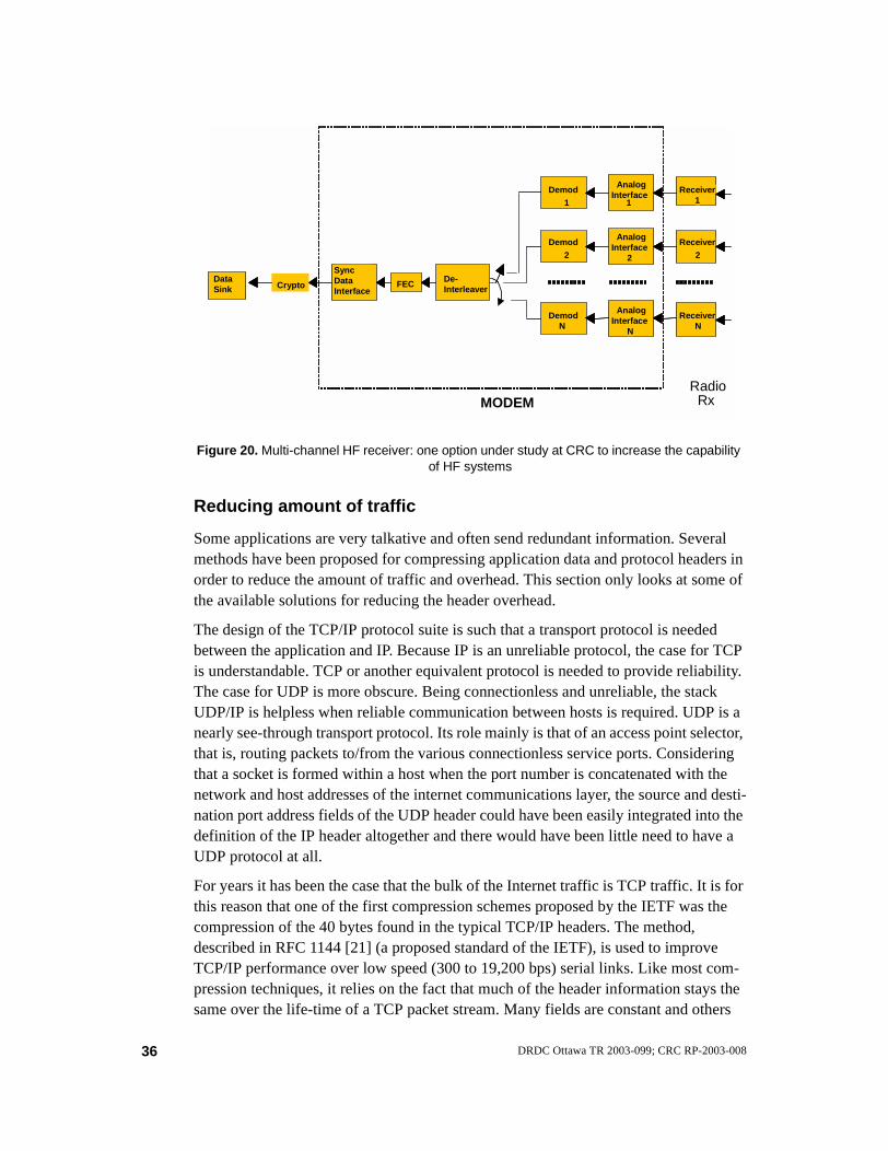
Reducing amount of traffic
Some applications are very talkative and often send redundant information. Several methods have been proposed for compressing application data and protocol headers in order to reduce the amount of traffic and overhead. This section only looks at some of the available solutions for reducing the header overhead.
The design of the TCP/IP protocol suite is such that a transport protocol is needed between the application and IP. Because IP is an unreliable protocol, the case for TCP is understandable. TCP or another equivalent protocol is needed to provide reliability. The case for UDP is more obscure. Being connectionless and unreliable, the stack UDP/IP is helpless when reliable communication between hosts is required. UDP is a nearly see-through transport protocol. Its role mainly is that of an access point selector, that is, routing packets to/from the various connectionless service ports. Considering that a socket is formed within a host when the port number is concatenated with the network and host addresses of the internet communications layer, the source and desti-nation port address fields of the UDP header could have been easily integrated into the definition of the IP header altogether and there would have been little need to have a UDP protocol at all.
For years it has been the case that the bulk of the Internet traffic is TCP traffic. It is for this reason that one of the first compression schemes proposed by the IETF was the compression of the 40 bytes found in the typical TCP/IP headers. The method, described in RFC 1144 [21] (a proposed standard of the IETF), is used to improve TCP/IP performance over low speed (300 to 19,200 bps) serial links. Like most com-pression techniques, it relies on the fact that much of the header information stays the same over the life-time of a TCP packet stream. Many fields are constant and others
Data Sink Crypto
Sync Data Interface
FECDe-Interleaver
Demod1
Receiver1
Demod2
DemodN
AnalogInterface
1
AnalogInterface
2
AnalogInterface
N
Receiver2
ReceiverN
MODEMRadio
Rx
Figure 20. Multi-channel HF receiver: one option under study at CRC to increase the capability of HF systems
36 DRDC Ottawa TR 2003-099; CRC RP-2003-008

change with small and predictable values and need not be retransmitted over and over with each new datagram. Under optimal conditions, TCP/IP compression can reduce the 40 byte overhead to 4 bytes.
Today, with many real-time applications running on top of UDP, the need to compress UDP headers for more efficient use of bandwidth, especially over low and medium speed links, is more present than ever. In February 1999, the IETF released three RFCs that partially address the issue for point-to-point links. They are:
• RFC 2507 [22], which defines compression for both TCP and UDP transport pro-tocol headers. The compression can be used for both IPv4 and IPv6 or even for packets encapsulated with multiple IP headers such as when packets are tunnelled, for example because Mobile IP is used.
• RFC 2508 [23], which defines compression for RTP/UDP/IP headers. It is designed to solve the specific problem of sending multi-media information, such as audio and video, over low-speed serial links using dialup modems. The com-pression scheme may be used with IPv4, IPv6 or packets encapsulated with more than one IP header, although the document focuses on IPv4.
• RFC 2509 [24], which describes an option for negotiating the use of header com-pression on IP datagrams transmitted over the Point-to-Point Protocol (PPP).
There are some important deficiencies with all of the above compression approaches. Both RFC 1144 and 2507 do not compress RTP headers whereas the other two do not perform well on lossy links with long round trip times. To resolve the issue, the IETF created the Robust Header Compression (ROHC) Working Group to develop generic header compression schemes that perform well over links with high error rates and long link round-trip times, as well as related signalling compression schemes. In July 2001, the ROHC Working Group published RFC 3095 [25], an IETF Standards Track document. The document specifies a robust and efficient header compression scheme for four different profiles: RTP/UDP/IP, UDP/IP, ESP/IP (Encapsulating Security Pay-load) and uncompressed. Since the specification is designed to be extensible, other profiles like compression of IP headers only may be added at a later date.
An issue that the ROHC group is currently working on is to develop a profile for com-pressing TCP/IP and to implement mechanisms that significantly improve the com-pression efficiency in unidirectional operation mode compared to the one obtained with a simple control scheme.
Rerouting traffic
Another alternative for dealing with a bandwidth shortage is to let some other link han-dle the problem. Rerouting traffic towards links that are lightly loaded may create fur-ther problems if it is not done carefully. After years of research and experimentation, the IETF has come up with two official routing protocol standards: RIP2 and OSPF2. Both offer some unique advantages. It is not clear how long it will take for these two protocols to replace, if they ever do, RIP, OSPF, BGP4, IS-IS, and some other common routing protocols that have been used for years in the Internet. The IETF has reserved
37DRDC Ottawa TR 2003-099; CRC RP-2003-008

STD #4 to specify the requirements for Internet routers. At present, RFC 1812 speci-fies requirements for IP version 4 routers only.
The problems with IP routing are well understood but the subject is broad and remains an active area of research since the current solutions are far from being optimal. We will limit the discussion to a few aspects using the exotic fish-like topology shown in Figure 21.
Let us assume that the source nodes are a and b, the destination is node c. To reach c, the traffic must flow through one of the two bearers A or B. Although there are two paths to reach c, if bearer A has more capacity than B, the traffic from both a and b will flow through A alone because the shortest path cost will typically be less for the path going through A than the path going through B. This problem is known as the “fish” problem [26][27], and is caused by the fact that routers by default keep only one path for each destination in their routing table. The situation can be improved using no less than four different traffic engineering techniques:
• load splitting;
• dynamic adaptive routing;
• constraint-based routing
• bandwidth brokering.
Load splitting, also known as load-balancing, consists in distributing network traffic in a fair way to two or more outgoing links. In the case scenario given in Figure 21, the traffic from a and b towards c would be split either equally or perhaps to some other suitable ratio between bearers A and B. There exists various traffic-splitting schemes (packet-by-packet round robin, direct or table-based hashing), especially useful when there are more than two possible outgoing links at a site and the amount of traffic is large. One important requirement of any load splitting scheme is to preserve per-flow packet ordering. Transmitting over links of different channel characteristics may cause packets or messages to arrive out-of-order at the destination, which may result in per-formance degradation when a reliable transport protocol like TCP is used. One exam-ple of a load sharing sequence error problem is reported in a Message Ordering Vulnerability Study that tried to balance loading across advanced tactical SATCOM
Figure 21. The well known “fish” topology
a
b
c
A
B
flow direction
38 DRDC Ottawa TR 2003-099; CRC RP-2003-008

links [28]. Finally, it is worth noting that the Equal-Cost Multi-Path (ECMP) option of OSPF is useful in distributing load to several shortest paths.
Dynamic adaptive routing consists in making the rerouting of traffic automatic in order to optimise the resource utilization in the network. The routing decisions are based on link metric values that are derived in real-time from the network traffic patterns. In the scenario described in Figure 21, the two bearers A and B may decide to adjust the cost advertised for their outgoing link according to the capacity remaining (not used up by the present flows) or some other performance optimisation criteria. If for instance bearer A becomes heavily loaded because of the traffic received from a and b, it may decide to advertise a higher path cost for its link to c. Doing so, the access router near a and b will decide that bearer B is now on the best route and the traffic will be rerouted through B. After a while, B also may experience congestion whereas A would have become idle. A cost advertisement update from B will reverse the path selection. This situation can cause permanent route oscillation.
In 1995, six NATO nations completed phase 1 of the Communications System Net-work Interoperability (CSNI) Project, which had for overall objective to evaluate the use of commercial standards in a military context [29]. A sub-objective of the project was to determine if the ISO 10589 dynamic routing protocol could be applied effec-tively to military communication networks. A simulation study of the protocol was carried out based on subnetworks of mixed characteristics and QoS metrics [30]. Some of the findings of the study include:
• the recommended default ISO 10589 timer values could not be used with the test network topology without causing routing instabilities. Most timers controlling the distribution of link state information and neighbour connectivity detection needed to be relaxed to achieve stability.
• the network could become unstable if the transient period exceeded the QoS mea-surement period.
• for low capacity bearers, the overhead associated with ISO 10589-based dynamic routing was too great for such approach to be practical. The amount of overhead was particularly severe over the low bandwidth broadcast circuits due to the pad-ding of the LAN IS-IS Hello PDU’s. The circuits handling the pseudo node func-tions on behalf of the LAN’s consumed more bandwidth than all the other circuit types.
The weakness of the dynamic adaptive routing approach in both IP and CLNP is that the routing algorithms are destination-based and “selfish” in the sense that link metrics are used to meet the requirements of one particular packet. There is no unified attempt to optimise the overall traffic flow in the network.
Constraint-based routing attempts to find a path that meets a particular request but with due consideration for the network-wide impacts. Each node obtains information about networkwide traffic demands in addition to the usual topological information. The optimisation goal is most often to balance the traffic distribution across the net-work to avoid hot spots. According to Wang [26], when all links are utilized to the
39DRDC Ottawa TR 2003-099; CRC RP-2003-008

same level, the network tends to perform at an optimal level in terms of packet loss, total delay, and bandwidth efficiency. Because of the need to precisely control the traf-fic distribution across the network, the routes produced by constraint-based routing are set up using virtual circuits adapted to the traffic patterns. In IP-based networks, both ATM and MPLS can be used for this purpose.
Bandwidth Brokering shares the same goal as constraint-based routing: managing the bandwidth resources to the network’s best interests. Bandwidth Broker (BB) agents are entities designed to keep track of current bandwidth consumption and perform admis-sion control, resource provisioning and other policy decisions in an administrative domain. When resource utilization has reached a low threshold and additional band-width is needed to accommodate new traffic requests, a BB in a domain can communi-cate with a BB in an adjacent domain to dynamically negotiate an interdomain bandwidth allocation.
Making better use of bandwidth
The last but not the least of alternatives for dealing with a bandwidth shortage is to decide how to best share the available network resources among the end-users. This is a very challenging task. Dynamic bandwidth allocation schemes, resource reservation/allocation schemes, QoS schemes such as IntServ and DiffServ are all about making better use of the network resources —the available bandwidth in particular.
1. Resource reservation
IP, as a best effort service, does not provide performance assurance. The integration of graded services at the IP layer is a trade off of the best effort packet delivery approach for schemes that are path or flow oriented. At one extreme, there is the datagram switching approach with its connectionless service offering little or no assurance of performance, and at the other end, the virtual circuit switching approach with its con-nection-oriented service offering full performance guarantee (Figure 16). The first does not reserve resources and processes packets individually without considering the fact that the packet may belong to a flow where all similar packets deserve, at times, particular treatment. The second makes absolute reservation of the network resources, leaving a path open, waiting (that is, this approach is often a waste of resources) for packets to flow through. From 100% to 0% service assurance (Figure 22), there is in-between room for providing differentiated degradation of performance for different traffic when traffic load is heavy. QoS is all about maintaining the quality of the packet flow. Or, as Wang [26] puts it, QoS is “the capability to provide resource assurance and service differentiation in a network”.
40 DRDC Ottawa TR 2003-099; CRC RP-2003-008

2. IntServ over DiffServ
QoS has been studied within the Internet for many years. The two distinct approaches, the Integrated Services architecture (IntServ) with its accompanying signalling proto-col, Resource ReSerVation Protocol (RSVP), and the Differentiated Services architec-ture (DiffServ), are only partially addressing all the needs of the wide Internet. DiffServ was developed after concerns were raised about the scalability of the IntServ model. The problem with DiffServ is that it does not provide absolute service assur-ance since it relies on flow aggregation to manage the service. A trend is developing where both models are cascaded to complement each other and support the delivery of end-to-end QoS: Diffserv in the core network, IntServ in the access networks. Intserv enables hosts to request per-flow, quantifiable resources, along end-to-end data paths and to obtain feedback regarding admissibility of these requests. Diffserv enables scal-ability across large networks. This integration model is described in RFC 2998 “A Framework for Integrated Services Operation over Diffserv Networks” (informa-tional), an informational document produced by the ISSLL (Integrated Services over Specific Link Layers) Working Group of the IETF.
An example where the IntServ over DiffServ model is being further investigated is in the IST-MIND/BRAIN project. A study found that there are weaknesses with this solu-tion when the communication architecture must support both wireless access and mobile users. To solve the particular problems identified, some extensions have been specifically developed under the project [31].
Assured Expedited Forwarding - PHB Forwarding - PHB
Controlled Load ServiceGuaranteed
ServiceBestEffort
0%Guarantee
100%Guarantee
noresourcereservation
absoluteresource
reservation
Plain IP
DiffServIntServ
Figure 22. QoS, the great challenge
packet-basedapproach
datagram switchingconnectionless service
flow-basedapproach
virtual circuit switchingconnection-oriented service
41DRDC Ottawa TR 2003-099; CRC RP-2003-008

3. MPLS and traffic engineering
Despite the progress made with DiffServ, the switching debate around “datagram” vs “virtual circuit” does not go away easily. Many satellite networks and backbone net-works run IP but are ATM-based. Internet Service Providers (ISPs) make use of the Multiprotocol Label Switching (MPLS) technology to manage the performance of their networks. This is because it is necessary to have explicit control over the paths that traffic flows traverse to be able to arrange and maximize resource commitments and utilization of the network. This is also what IntServ tries to achieve for end-user traffic but in a more complex way.
4. Mechanisms
What are the mechanisms used in IP networks to better manage bandwidth and other QoS requirements? There are many and we cannot review them all here. Firoiu et al. [32] note that QoS control mechanisms have key aspects in two dimensions: time and space. The time scale at which a control operates are as follows:
• fastest (~1-100s us) i.e. at packet level. e.g. traffic conditioning devices (e.g. traffic classifiers, markers, policers, and shapers), packet schedulers, and active queue management;
• round-trip-time (~1-100s ms) i.e. at scale where feedback-based QoS control mechanisms operate e.g. congestion and flow controls;
• session (seconds, minutes or longer) i.e. duration of user sessions e.g. admission control and QoS routing;
• slowest (minutes, hours, days, weeks or months) e.g. traffic engineering, time-of-day service pricing, resource provisioning and capacity planning.
The second dimension of this 2-D taxonomy is space, which relates to:
• granularity of control:
• finest is the per-flow state information e.g. as identified by the 5-tuple: the IP source (address, port number), destination (address, port number), and protocol field;
• coarser e.g. for an aggregate of user flows, such as per host, per network prefix, per ingress-egree pair, per service class, etc.;
• the carrier of control state (i.e. where the control state is stored) e.g. in routers, or in the packet header only;
• the location of control (i.e. where a control mechanism operates) e.g. at the end-hosts, the network edge or boundaries between either users and network or net-work domains, or inside the network core.
These two dimensions together define a broad design space from which QoS provi-sioning architectures can be built, reflecting various trade-offs in QoS service perform-ance, operations and management complexity and implementation cost.
The need to internetwork with an ever diversified variety of environment (consider, for example, the case shown in Figure 23) is driving this research towards ancillary direc-
42 DRDC Ottawa TR 2003-099; CRC RP-2003-008
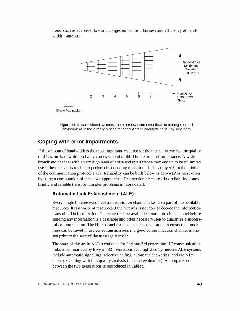
tions, such as adaptive flow and congestion control, fairness and efficiency of band-width usage, etc.
Coping with error impairments
If the amount of bandwidth is the most important resource for the tactical networks, the quality of this same bandwidth probably comes second or third in the order of importance. A wide broadband channel with a very high level of noise and interference may end up to be of limited use if the receiver is unable to perform its decoding operation. IP sits at layer 3, in the middle of the communication protocol stack. Reliability can be built below or above IP or most often by using a combination of these two approaches. This section discusses link reliability issues briefly and reliable transport transfer problems in more detail.
Automatic Link Establishment (ALE)
Every single bit conveyed over a transmission channel takes up a part of the available resources. It is a waste of resources if the receiver is not able to decode the information transmitted in its direction. Choosing the best available communication channel before sending any information is a desirable and often necessary step to guarantee a success-ful communication. The HF channel for instance can be so prone to errors that much time can be saved in useless retransmissions if a good communication channel is cho-sen prior to the start of the message transfer.
The state-of-the-art in ALE techniques for 2nd and 3rd generation HF communication links is summarized by Elvy in [33]. Functions accomplished by modern ALE systems include automatic signalling, selective calling, automatic answering, and radio fre-quency scanning with link quality analysis (channel evaluation). A comparison between the two generations is reproduced in Table 9.
Bandwidth or
Single flow packet
MaximumTransfer
Figure 23. In narrowband systems, there are few concurrent flows to manage. In such environment, is there really a need for sophisticated priority/fair queuing schemes?
Number of2 3 4 5 6 7 Concurrent
Unit (MTU)
Flows
43DRDC Ottawa TR 2003-099; CRC RP-2003-008
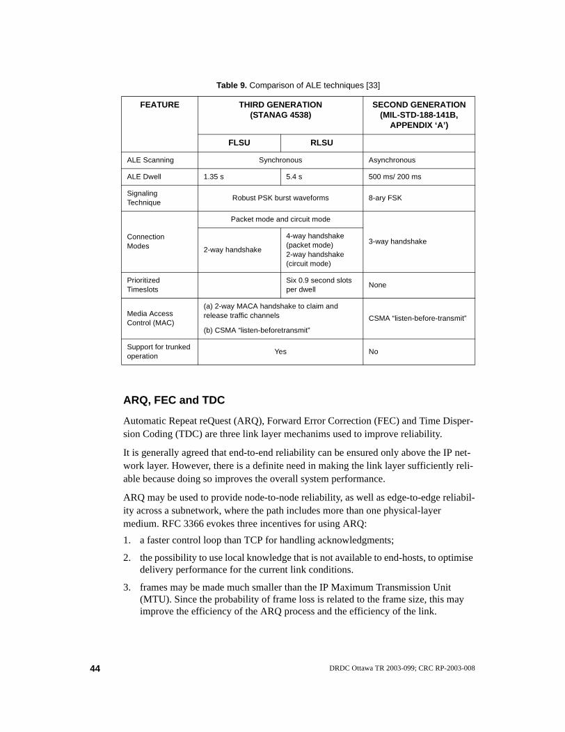
ARQ, FEC and TDC
Automatic Repeat reQuest (ARQ), Forward Error Correction (FEC) and Time Disper-sion Coding (TDC) are three link layer mechanims used to improve reliability.
It is generally agreed that end-to-end reliability can be ensured only above the IP net-work layer. However, there is a definite need in making the link layer sufficiently reli-able because doing so improves the overall system performance.
ARQ may be used to provide node-to-node reliability, as well as edge-to-edge reliabil-ity across a subnetwork, where the path includes more than one physical-layer medium. RFC 3366 evokes three incentives for using ARQ:
1. a faster control loop than TCP for handling acknowledgments;
2. the possibility to use local knowledge that is not available to end-hosts, to optimise delivery performance for the current link conditions.
3. frames may be made much smaller than the IP Maximum Transmission Unit (MTU). Since the probability of frame loss is related to the frame size, this may improve the efficiency of the ARQ process and the efficiency of the link.
Table 9. Comparison of ALE techniques [33]
FEATURE THIRD GENERATION(STANAG 4538)
SECOND GENERATION(MIL-STD-188-141B,
APPENDIX ‘A’)
FLSU RLSU
ALE Scanning Synchronous Asynchronous
ALE Dwell 1.35 s 5.4 s 500 ms/ 200 ms
SignalingTechnique
Robust PSK burst waveforms 8-ary FSK
ConnectionModes
Packet mode and circuit mode
3-way handshake2-way handshake
4-way handshake (packet mode)2-way handshake(circuit mode)
PrioritizedTimeslots
Six 0.9 second slots per dwell
None
Media AccessControl (MAC)
(a) 2-way MACA handshake to claim and release traffic channels
(b) CSMA “listen-beforetransmit”
CSMA “listen-before-transmit”
Support for trunkedoperation
Yes No
44 DRDC Ottawa TR 2003-099; CRC RP-2003-008
ARQ protocols are characterised by their persistency i.e. by how long they are allowed to hold on to a packet in an attempt to successfully transmit it over the link. The higher the persistency level, the higher the chances that the protocol will provide a reliable service.
Should ARQ protocols be allowed to forward packets in any order? The answer is “yes, in principle” and probably “no, in practice”. Yes, because IP neither offers nor expects a reliable in-order delivery service. No, because reordering may increase delay jitter of multi-media and real-time packets. Reordering may also mislead a transport protocol like TCP to believe that some packets have been lost.
For handling QoS-based traffic, it is desirable that the ARQ protocol be able to differ-entiate different classes of flows. There is no point in trying to achieve a high degree of reliability using high persistence ARQ if the flow does not require it (e.g. delay-sensi-tive flows like voice and some real-time traffic). One way for the protocol to distin-guish the class of a packet is to inspect the packet header. This may not always work well when the ToS/DS values are not set reliably or flows of different transport classes are tunnelled.
ARQ, FEC and bit interleaving (a TDC technique) are often used together over lossy channels. FEC uses some of the available bandwidth whereas interleaving adds delay to the transmission.
TCP and its various flavours
TCP is the IETF’s recommended transport protocol to use when no assumption can be made about the reliability of the network. At the very least, TCP can be viewed as one of the mechanisms built into the early Internet architecture to enhance the quality of service of IP networks. Many flavours of TCP exist and all kinds of surrogate solutions have been and continue to be proposed to achieve and guarantee a desired level of communication that is superior to the “best effort” level that IP has to offer. TCP is probably the most studied protocol of all the protocols. Many excellent reviews have been published in recent years about the issues and possible enhancements regarding the use of TCP over difficult links. This section discusses some of these issues.
TCP is said to have been designed to operate over highly reliable links and stationary hosts. Well, perhaps, although TCP was run over the DARPA Packet Radio Network (PRNET) as part of the feasibility research of using packet-switched, store-and-for-ward radio communications to provide reliable computer communications. Also, it is generally said that TCP assumes all packet losses to be caused by network congestion. This last statement is more to the point because the original design of TCP was intended to do more than just provide a reliable end-to-end communication service in a multinetwork environment. In RFC 793, which originally specified TCP, it is stated that the operation of TCP involves six “facilities”, which are shown in Figure 24.
45DRDC Ottawa TR 2003-099; CRC RP-2003-008

Except for the Precedence and Security element, which today has become a global issue well beyond the scope of TCP, the basic protocol design concepts are still remarkably pertinent and valid. However, the protocol is not without problems.
Clark et al. [34] note that the reason TCP fails to perform well in some environment is that its control mechanisms interact in a complicated, sub-optimal way. Four key prob-lem areas with TCP when the link quality is less than perfect are presented in details by Taferner and Bonek in [5] and can be summarized as follows:
1. Poor behaviour on packet loss. Every error detected by TCP causes a congestion window drop, which in turn reduces the amount of data injected into the link. The two elements “Reliability” and “Flow Control” interact in a way that was not meant to be.
2. Poor behaviour on temporary link disconnection. If the link quality degrades to the point where packet exchange is suppressed for a time that exceeds TCP’s retransmission timer, the reaction of TCP to such disconnection is, again, to reduce the congestion window. Furthermore, the retransmission time is doubled for the next transmission period, leading to an exponential increase of the retransmission timer. The net result is a long idle time in data transmission.
3. Adverse interactions with link layer mechanisms. Tactical bearers often rely on ARQ and FEC techniques to improve the communication reliability at the link layer level. Depending on the link quality, these schemes introduce some variabil-ity in capacity and delay of the service offered by the layer. As TCP/IP relies on the link layer service, several interaction can cause potential problems. These are as follows:
• Deceptive RTT estimation. TCP performs its own RTT estimation by calcu-lating a running average for every packet acknowledged without retrans-mission. This estimate is unreliable and can lead to severe performance degradation.
Reliability
Basic
Flow Control Multiplexing
ConnectionsPrecedence
DataTransfer
andSecurity
Figure 24. The genuine raison d’être of TCP as specified in RFC 793 and some of the TCP flavours developed over the years
TCP Reno
TCP Vegas
TCP New Reno
T/TCP
I-TCP
M-TCP
TCP-Bus
TCP Snoop
TCP AdaVegas
TCP-F
WTCP
TCP BostonTCP Westwood
TCP PeachTCP SACK
TCP FACKTCP TACK
Freeze TCPTCP Santa Cruz
TCP Smooth-start
TCP Robust-recoverySCPS-TP
TCP Buffer fill avoidancepTCP
TCP Tahoe TCPW BR
46 DRDC Ottawa TR 2003-099; CRC RP-2003-008

• Entangled delivery. The link layer protocol must maintain in-order delivery of packets otherwise TCP may send duplicate acknowledgments to the sender for packets delivered out-of-order to TCP.
• Competing retransmissions. Retransmissions of the same lost data by both the link layer and TCP are possible.
4. Poor performance in asymmetric channels. TCP sends data as fast as it receives acknowledgments. If the bandwidth available in one direction limits the rate of acknowledgments sent towards the sender, the latter will not be able to make full use of the bandwidth available to send information. Acknowledgment traffic needs considerable resources and various mechanisms have been proposed to improve on this situation, including filtering and delaying acknowledgments [35]. Both techniques are possible because TCP acknowledgments are cumulative and only the last acknowledgment is necessary to transmit.
Various solutions are possible to each of the problems mentioned above but if the number of variants developed around the TCP protocol is any indication, there is hardly one approach that has been found suitable to these problems and others in all cases. In general, the IETF is careful about recommending new optimisation mecha-nisms for TCP, and even more so in adopting new standards. Table 10 provides a non-exhaustive list of RFCs regarding the work done on TCP in the IETF. The list only includes one standard but ten proposed standards, six BCP or informational documents and four experimental proposals.
In general, the specification developed by the IETF works well over a wide range of communication systems but unless non-standard mechanisms are applied, performance degrades significantly in some environments, such as those where errors and variable delays are present.
A number of extensions to TCP have been added over the years and are now consid-ered “standard” mechanisms suitable for most networks in general. A modern imple-mentation of TCP usually consists of:
• the basic TCP, as specified in RFC 793 and implemented according to discussions and recommendations given in RFC 1122 (STD003), which includes design clari-fications, error corrections and an explicit set of requirements for the Internet hosts, and,
• the TCP Reno modifications, as specified in RFC 2581. These modifications spec-ify four TCP congestion control algorithms devised by Jacobson: slow start, con-gestion avoidance, fast retransmit and fast recovery.
Some more advanced implementations may also be based on TCP Vegas [36], which is an alternative implementation that confines all new modifications to the sending side of TCP. This makes Vegas interoperable with any other previous version of TCP. In TCP Vegas a new retransmission mechanism, modification of the slow start mecha-nism and introduction of a congestion avoidance algorithm provide significantly better throughput (up to 71%) and losses reduction (up to 50%).
47DRDC Ottawa TR 2003-099; CRC RP-2003-008
Much more could be said about other specific TCP variants but with so many of them around, one has to ask: Is TCP an appropriate protocol model for wireless networks? This is precisely the question that Balakrishnan et al. ask themselves in [37]. Their answer is “We believe it is” and they justify their answer by the fact that so many applications are built on top of TCP and will continue to be in the foreseeable future. Taferner and Bonek discuss the solutions that have been proposed recently to alleviate the poor performance of unmodified TCP when operating over wireless links. The solutions are classified into three groups [5]:
1. End-to-end proposals, where the modifications are restricted to the endpoints. This group includes improvements such as:
• fast retransmission and fast recovery algorithms, such as those found in TCP Reno and Vegas;
• use of the Selective Acknowledgment (SACK) TCP option, such as the one specified in RFC 2018;
• TCP support for mobility awareness, which introduces new mobility fea-tures to make TCP aware of the mobility of the end-users. The M-TCP pro-tocol [38] for instance, designed to handle long and frequent disconnections as well as lossy channels;
• making TCP distinguish between congestion and loss of data.
2. Split-connection proposals, where an optimised version of TCP or some other transport protocol is used over the radio portion of the link, and a conventional TCP version is used over the land portion of the link. This approach requires breaking the normal TCP connection at an intermediate node into two separate connections. Indirect-TCP (I-TCP), Snoop TCP and Wireless-TCP (WTCP) are examples of this approach.
3. Link layer proposals. This approach has already been considered above. ARQ and FEC schemes are used to improve the reliability of the link data transfer.
Although the deployment of the TCP protocol is widespread, TCP is likely to remain a trendy topic of research for some time again.
48 DRDC Ottawa TR 2003-099; CRC RP-2003-008

Table 10. TCP-related RFCs trying to make TCP independent of the underlying network technology
DOCUMENT TITLE STATUS DATE
RFC 3522 The Eifel Detection Algorithm for TCP Experimental Apr’03
RFC 3517 A Conservative Selective Acknowledgment (SACK)-based Loss Recovery Algorithm for TCP.
ProposedStandard
Apr’03
RFC 3481 TCP over Second (2.5G) and Third (3G) Generation Wireless Networks
Best Current Practice
Feb’03
RFC 3449 TCP Performance Implications of Network Path Asymmetry
Best Current Practice
Feb’03
RFC 3390 Increasing TCP's Initial Window. (Updates RFC2581)
ProposedStandard
Oct’02
RFC 3168 The Addition of Explicit Congestion Notification (ECN) to IP
ProposedStandard
Sep’01
RFC 3042 Enhancing TCP’s Loss Recovery Using Limited Transmit
ProposedStandard
Jan’01
RFC 2923 TCP Problems with Path MTU Discovery Informational Sep’00
RFC 2883 An extension to the Selective Acknowledgement (SACK) option for TCP
ProposedStandard
Jul’00
RFC 2873 TCP processing of the IPv4 Precedence Field ProposedStandard
Jun’00
RFC 2760 Ongoing TCP Research Related to Satellites Informational Feb’00
RFC 2582 The NewReno Modification to TCP’s Fast Recovery Algorithm
Experimental Apr’99
RFC 2581 TCP Congestion Control ProposedStandard
Apr’99
RFC 2488 Enhancing TCP over satellite channels using standard mechanisms
Best Current Practice
Jan’99
RFC 2414 Increasing TCP’s initial window Experimental Sep’98
RFC 2018 TCP selective acknowledgment options ProposedStandard
Oct’96
RFC 1323 TCP extensions for high performance ProposedStandard
May’92
RFC 1263 TCP Extensions Considered Harmful Informational Oct’91
RFC 1146 TCP alternate checksum options Experimental Mar’90
RFC 1144 Compressing TCP/IP headers for low-speed serial links
ProposedStandard
Feb’90
RFC 793 Transmission Control Protocol(updated by RFC 3168)
Standard Sep’81
49DRDC Ottawa TR 2003-099; CRC RP-2003-008

Coping with delay impairments
In this section we look at the problems in long range communications, e.g. over HF or via sat-ellite, where the high latency across a link can adversely affect throughput. As discussed in Section 2., the round-trip time, RTT, and the bandwidth-delay product, DBP, are two key parameters that characterize these types of links.
BCP for satellite channels
Nguyen [39] suggests a classification of satellite systems based on three areas: their operating orbits, service provision, and system properties (bandwidth). A summary of his classification is shown in Figure 25.
In 1999, the IETF has come up with a set of Best Current Practices (BCP 28, RFC 2488) about enhancing the TCP performance over satellite channels using standard mechanisms. A summary of the practices is given in Table 11. The document only con-siders TCP mechanisms that are currently well understood and on the IETF standards track (or are compliant with IETF standards).
The Path-MTU Discovery mechanism, documented in RFCs 1191 and 1435, deter-mines the maximum transfer unit (MTU) or packet size a connection can use on a given network path without being subjected to IP fragmentation. This reduces packet overhead by preventing unnecessary fragmentation and reassembly. Running the Path-MTDU Discovery mechanism to determine the maximum allowable packet size takes time. The process can be speeded up by caching MTU values but the exact implemen-tation of this and the aging of cached values remains an open problem.
Fixed
Bandwidth Geo
stat
iona
ry E
arth
Orb
it
Med
ium
Ear
th O
rbit
Low
Ear
th O
rbitBroadband systems
Orbit T
ype
Satellite Service Type
Narrow-band systems
Figure 25. Classification of satellite systems
Mob
ile
Broad
cast
voice and low bit rate data (up to 9.6 kbps)e.g. Iridium, GlobalStar
interactive multimedia and IP-based servicese.g. next generation of satcom networks
50 DRDC Ottawa TR 2003-099; CRC RP-2003-008
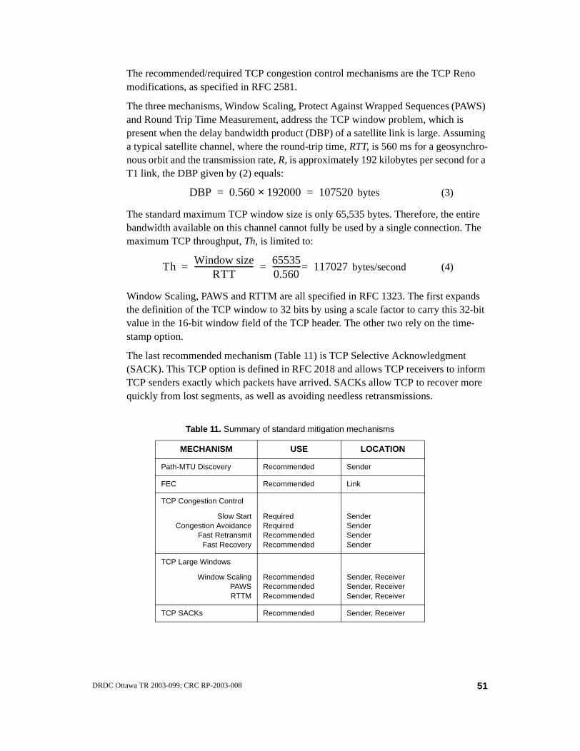
The recommended/required TCP congestion control mechanisms are the TCP Reno modifications, as specified in RFC 2581.
The three mechanisms, Window Scaling, Protect Against Wrapped Sequences (PAWS) and Round Trip Time Measurement, address the TCP window problem, which is present when the delay bandwidth product (DBP) of a satellite link is large. Assuming a typical satellite channel, where the round-trip time, RTT, is 560 ms for a geosynchro-nous orbit and the transmission rate, R, is approximately 192 kilobytes per second for a T1 link, the DBP given by (2) equals:
bytes (3)
The standard maximum TCP window size is only 65,535 bytes. Therefore, the entire bandwidth available on this channel cannot fully be used by a single connection. The maximum TCP throughput, Th, is limited to:
bytes/second (4)
Window Scaling, PAWS and RTTM are all specified in RFC 1323. The first expands the definition of the TCP window to 32 bits by using a scale factor to carry this 32-bit value in the 16-bit window field of the TCP header. The other two rely on the time-stamp option.
The last recommended mechanism (Table 11) is TCP Selective Acknowledgment (SACK). This TCP option is defined in RFC 2018 and allows TCP receivers to inform TCP senders exactly which packets have arrived. SACKs allow TCP to recover more quickly from lost segments, as well as avoiding needless retransmissions.
Table 11. Summary of standard mitigation mechanisms
MECHANISM USE LOCATION
Path-MTU Discovery Recommended Sender
FEC Recommended Link
TCP Congestion Control
Slow StartCongestion Avoidance
Fast RetransmitFast Recovery
RequiredRequiredRecommendedRecommended
SenderSenderSenderSender
TCP Large Windows
Window ScalingPAWSRTTM
RecommendedRecommendedRecommended
Sender, ReceiverSender, ReceiverSender, Receiver
TCP SACKs Recommended Sender, Receiver
DBP 0.560 192000× 107520= =
ThWindow size
RTT------------------------------- 65535
0.560--------------- 117027== =
51DRDC Ottawa TR 2003-099; CRC RP-2003-008

SCPS-TP and other PEPs
Another set of recommendations aimed at enhancing the TCP performance over satel-lite channels comes from the Consultative Committee for Space Data Systems (CCSDS) organization. SCPS-TP stands for Space Communications Protocol Specifi-cation - Transport Protocol. These specifications were developed by MITRE Corpora-tion based on DoD/NASA requirements that were set in 1993 to support spacecraft communication environments. The recommendations were officially released in 1999. The specifications have been endorsed by ISO in 2000. The recommendations are reviewed by the CCSDS no later than five years from their date of issuance to deter-mine whether they should remain in effect, be changed, be retired or cancelled.
SCPS-TP advocates a performance mitigation technique that a number of commercial implementations, using a similar approach but with proprietary specifications, have made available in recent years and which apparently offer excellent performance.
SCPS-TP is based on TCP/UDP and many of the same extensions that have been dis-cussed in other sections of this document. These include:
• Window scaling, PAWS, and RTTM (RFC 1323);
• Selective Negative Acknowledgment (SNACK) (adapted from RFC 1106);
• Header Compression (adapted from RFC 1144);
• Rate Control (optional non-use of congestion control);
• Retransmission strategies for space environments that accommodate loss due to data corruption, link outages, and congestion;
• TCP for Transactions (RFC 1644);
• Best Effort Transport Service (BETS);
• Low-loss congestion control (e.g. TCP Vegas).
SCPS-TP is one member of the Performance Enhancing Proxies (PEP) intended to mitigate link-related degradations. The IETF has recently (June 2001) conducted a sur-vey of PEPs and released the results in RFC 3135. The document bears the informa-tional status and does not make recommendations about using PEPs or not using them. The document warns that if PEP is used, it should be implemented in a way that end-users are aware of its existence and should be given the capability to bypass it and run end-to-end IP at all times but, of course, without the performance enhancements that employing the PEP may yield. This is because PEP can interfere with end-to-end usage of IP layer security mechanisms or otherwise have undesirable implications in some circumstances.
SCOPE
Satellite Capacity Optimisation and Performance Enhancement (SCOPE) is an engi-neering solution being developed by the VPSAT/RMSC group at CRC to improve sat-ellite communications when dealing with Internet-like traffic. SCOPE amalgamates
52 DRDC Ottawa TR 2003-099; CRC RP-2003-008

two well known concepts. In a nutshell, the two basic elements of SCOPE are a Satel-lite Capacity Optimiser (SCO) and a Performance Enhancer (PE).
The SCO element optimises the bandwidth resource utilization of a TDMA satellite by using a Dynamic Bandwidth Allocation (DBA) scheme. DBA is a distant child of the Demand Assigned Multiple Access (DAMA) family, which dates back to the 1970's when the first schemes were experimented on some UHF military satellites. The pro-posed solution wants to be applicable to any type of satellite network but geosynchro-nous satcom systems are the prime focus for the current development. The SCO is designed to integrate some of the differentiated service (DiffServ) concepts in its archi-tecture.
The PE element improves the quality and efficiency of satellite communications by optimising the transport layer. More specifically, SCOPE uses a split segment network architecture where separate TCP connections, for the access and backbone networks, are managed by a proxy (transport-level gateway residing in the PE) and tailored to the particular requirements of each network side. The design aims at providing interopera-bility among end-users and is, to some extent, in accordance with the “Space Commu-nications Protocol Specification - Transport Protocol (SCPS-TP)”.
Long Thin Networks (LTN)
Satellite networks are not the only type of networks where long delays are a problem. The Performance Implications of Link Characteristics (PILC) Working Group of the IETF has tried to identify a TCP that works for all users. In January 2000, after review-ing the existing proposals along with advanced research items, the group released RFC 2757, an informational document, recommending mechanisms for implementation in long thin networks (see Section 2.) Their recommendations are summarized in Table 12.
53DRDC Ottawa TR 2003-099; CRC RP-2003-008

Table 12. Summary of PILC working group on recommended mechanisms for implementation in long thin networks (LTN)s
OPTION STABILITY OF THE PROPOSAL
LOCATION RECOMMENDATION
Increased Initial Window
RFC 2581(proposed standard)
Wireless senderYes(initial_window=2)
Disable delayed ACKs during slow start
not applicable Wireless receiver When stable
Byte counting instead of ACK counting
not applicable Wireless sender No
TCP header compression for PPP
RFC 1144(proposed standard)
Wireless deviceIntermediate node
Yes
IP payload compression(IPComp)
RFC 2393(proposed standard)
Wireless device Yes
Header compression
RFC 2507 and 2509(proposed standards)
Wireless deviceIntermediate node
Yes(for IPv4, TCP and Mobile IP, PPP)
SNOOP plus SACK
In limited useIntermediate nodeWireless device for SACK
Yes
Fast retransmit/fast recovery
RFC 2581(proposed standard)
Wireless deviceYes (should be there already)
Transaction TCPRFC 1644(experimental)
Wireless device No
Estimating slow start threshold
not applicable Wireless sender No
Delayed duplicate ACKs
not stableWireless receiverIntermediate node (for notifications)
When stable
Explicit congestion
RFC 2481|(experimental)
Wireless device Yes
Notification Network infrastructure
TCP control block interdependence
RFC 2140(informational)
Wireless deviceYes(track research)
54 DRDC Ottawa TR 2003-099; CRC RP-2003-008

QoS in Iris
The Iris System was designed prior to the time that resource assurance and service differentia-tion became a primary concern in the Internet. Nevertheless, the Iris network infrastructure was developed with the objective of providing a controlled system environment where bandwidth and connectivity are easy to manage, ensuring reliable delivery of messages and establishment of voice communication even when subjected to damage.
If any part of the system is destroyed or fails, the system has the built-in capability to restore communications services between the remaining elements using surviving alternate or surviv-ing backup connectivity without operator intervention. The addressing scheme, routing scheme, and adaption to changes in network load and configuration are automated.
Bandwidth allocation and dynamic routing
As shown in Figure 7, two key network protocols in Iris are the standard Internet Pro-tocol (IPv4) for data traffic (RFC 791) and the companion Stream Protocol -Version 2 (ST-II) for voice and facsimile traffic (RFC 1190). IP provides a packet switched con-nectionless service whereas ST-II provides a constant bit rate connection-oriented service. The standard ST-II functions are supplemented with a reverse stream capabil-ity to reduce overhead when creating duplex streams.
Routing is dynamic and adaptive using a proprietary protocol running the Shortest Path First (SPF) algorithm, which recalculates the best routing paths based on the link metrics in the topology. Every node maintains two forwarding tables, one for IP and one for ST-II. This is required to handle distinct IP and ST-II link metrics.
Both IP and ST-II metrics are composed of two components. The static component is administered through network management and relates to the link bandwidth. A reserved ST-II bandwidth is defined for TDN and LDN links as a percentage of the total link capacity. The dynamic component is load-dependent and is calculated from the weighted average of recent usage. The ST-II dynamic component is based on the spare ST-II bandwidth available on the link (the difference between the currently reserved ST-II bandwidth and the administrative maximum, as shown in Figure 26). The static and dynamic components are added to give a total metric value for the link.
Traffic prioritization
Both IP and ST-II run on top of the HIDS Bearer Service (HBS) protocol as shown in Figure 7 and discussed in Section 2. under the paragraph entitled “Commonality of the LAN/LDN/TDN Protocols”. HBS supports traffic prioritization by having tree priority queues for every outgoing link. The priority levels are: low, medium, and high. Packets with higher priority are transmitted first. There is a HIDS-wide assignment of virtual circuit ranges for different levels of traffic priorities. This allows for voice traffic to have precedence over data traffic whenever ST-II stream traffic must be forwarded for example.
55DRDC Ottawa TR 2003-099; CRC RP-2003-008

Users can place calls at one of three precedence levels: Routine, Priority, or Special Priority. The precedence level assigned to a call cannot be changed once the call has been established. Call preemption capabilities include subscriber preemption and trunk preemption. Subscriber preemption occurs when a high precedence call is coming to a terminal busy where a low-precedence call is ongoing. Trunk preemption occurs when there is insufficient voice bandwidth available on a TDN link to establish a high prece-dence call connection.
Traffic prioritization over the CNR net is handled differently than over the HIDS. To speak on a CNR net, the user must first activate the pressel switch of the voice termi-nal. A request to speak is immediately directed to the radio interface (over the MXS/UDP exchange) which determines if the CNR net is available for transmission. The radio interface arbitrates concurrent accesses on a first come, first serve basis. There is no provision to preempt the current speaker. If the radio is transmitting or receiving data when a request is received (mixed voice/data nets only), the radio interface fin-ishes transmission/reception of the current data packet before granting voice access.
Conclusion
In conclusion, if there is one thing that should be apparent, when analysing the various options mentioned throughout this document for making TCP/IP work in a wireless environment, it is the abundance of clever proposals and creative solutions, which in a way reflect both the weak-nesses and strengths of this protocol suite. IP is enormously flexible but is not without its prob-lems. A great deal of the many challenges facing the integration of graded services at the IP layer revolve around various techniques trading off the best effort packet delivery approach for schemes that are path or flow oriented. By doing so, network robustness, simplicity, transpar-ency and other design objectives originally part of the Internet design philosophy are poten-tially weakened or compromised. Focusing the development of tactical networks on just one switching technology leads to better interoperability and system integration, which no doubt are important considerations. However, one should keep an eye on the development of a diver-
Bandwidth available for new ST-II connections
Bandwidth available
for IP
Bandwidth currently reserved for ST-II connections
Total link bandwidth available
Maximum bandwidth allowed for ST-II traffic
Figure 26. IP and ST-II bandwidth allocation
56 DRDC Ottawa TR 2003-099; CRC RP-2003-008

sity of avenues so as to minimize the risk of latent vulnerabilities typically found in any single solution.
Armies and wars have changed quite a bit over the last century and the requirements for com-munications on the battle field or throughout the chain of command have never been more
demanding than now. While the information technology of the 21st century has the promise to revolutionize military communications, the current Internet infrastructure is on a complex evo-lutionary path. If the lack of QoS support is IP’s Achilles’ heel, on the horizon lies a growing burden of political, financial and administrative constraints — perhaps IP’s own Waterloo. The latter issues are beyond the scope of this report but should be considered when developing a vision for the future of IP and the Internet. In effect, the integration of IP-based communica-tions in strategic and tactical domains needs to progress carefully.
Reference1. Postel, J. (1983). Official Protocols, IETF, RFC 840
2. Handley, M., Crowcroft, J., Bormann, C., and Ott, J. (1999). Very large conferences on the Internet: the Internet multimedia conferencing architecture, Computer Networks, Vol. 31, pp. 191-204
3. Daniel, E.J. and Teague, K.A. (2001). Performance of FNBDT and Low Rate Voice (MELP) over Packet Networks, 35th Asilomar Conference on Signals, Systems, and Com-puters, Pacific Groove, CA
4. Dierks, T. and Allen, C. (1999). The TLS Protocol Version 1.0, IETF, RFC 2246
5. Taferner, M. and Bonek, E. (2002). Wireless Internet Access over GSM and UMTS, Springer-Verlag Berlin Heidelberg, New York
6. Rose, M. (2001). The Blocks Extensible Exchange Protocol Core, IETF, RFC 3080
7. Rose, M. (2002). An Overview of BEEP, The Internet Protocol Journal, Volume 5, No. 2
8. ETSI (2001), Services and Protocols for Advanced Networks (SPAN); Relationship between IP and telecommunication networks, EG 201 898 V1.1.1 (2001-04)
9. Rose, M., Klyne, G. and Crocker, D. (2002). The Application Exchange Core, IETF, RFC 3340
10. Teitelbaum, B. (2001). Future Priorities for Internet2 QoS, Internet2 QoS Working Group Draft
11. Miras, D. (2002). A Survey on Network QoS Needs of Advanced Internet Applications, Internet2 QoS Working Group
12. ITU-T (2000), Recommendation Y.1001: IP framework – A framework for convergence of telecommunications network and IP network technologies, International Telecommunica-tion Union - Telecommunication Standardization Sector
13. Garrett, M.W. (1996). A Service Architecture for ATM: from Applications to Scheduling, IEEE Network Magazine, May Issue
57DRDC Ottawa TR 2003-099; CRC RP-2003-008

14. Jha, S. and Hassan, M. (2002). Engineering Internet QoS, Artech House, Inc.
15. Schooler, E.M. (1997). QoS in the Internet: An Overview, Broadband Information Systems Lab, HP Labs, Palo Alto, CA
16. Garrett, M. and Borden, M. (1998). Interoperation of Controlled-Load Service and Guar-anteed Service with ATM, IETF, RFC 2381
17. Mirsky, S. (2002). Einstein’s Hot Time, Scientific American, September Issue
18. Taub, H. and Schillin, D.L. (1971). Principles of Communication Systems, McGraw-Hill, Inc., p 421
19. Allman, M., Glover, D., and Sanchez, L. (1999). Enhancing TCP Over Satellite Channels using Standard Mechanisms, IETF, RFC 2488
20. Tanenbaum A.S. (2003). Computer Networks, 4th edition, Prentice Hall PTR
21. Jacobson, V. (1990), Compressing TCP/IP Headers for Low- Speed Serial Links, IETF, RFC 1144
22. Degermark, M., Nordgren, B. and Pink, S. (1999). Header Compression for IP, IETF, RFC 2507
23. Casner, S. and Jacobson, V. (1999). Compressing IP/UDP/RTP Headers for Low-Speed Serial Links, IETF, RFC 2508
24. Engan, M., Casner, S. and Bormann, C. (1999). IP Header Compression over PPP, IETF, RFC 2509
25. Bormann, C., et al. (2001). RObust Header Compression (ROHC): Framework and four profiles: RTP, UDP, ESP, and uncompressed, IETF, RFC 3095
26. Wang, Z. (2001). Internet QoS - Architectures and Mechanisms for Quality of Service, Morgan Kaufmann Publishers
27. Dunn, L. (1999). The Internet2 Project, The Internet Protocol Journal, Volume 2 Number 4
28. Alspaugh, C. and Legaspi, A.K. (2002). A Violation of Order: IP-QoS for Tactical Traffic, MILCOM 2002
29. Gee, S. (1995). CSNI Overview, Proceedings of the Communications Systems Network Interoperability (CSNI) Symposium on Communications Internetworking, Symposium Proceedings STC SP-12, SHAPE Technical Centre, The Hague
30. Casey, R. and Bilodeau, C. (1995). Dynamic QoS-Based Routing, Proceedings of the Communications Systems Network Interoperability (CSNI) Symposium on Communica-tions Internetworking, Symposium Proceedings STC SP-12, SHAPE Technical Centre, The Hague
31. IST-2000-28584 MIND (2002), D2.2 annex, WP2 - Access Network Architecture
32. Firoiu, V., Le Boudec, J., Towsley, D., and Zhang, Z. (2001). Advances in Internet Quality of Service, http://dscwww.epfl.ch/en/publications/documents/tr00 049.pdf
33. Elvy, S.J. (2001). Comparison of Second and Third Generation HF Communication Links, RTO IST Symposium on “Military Communications”, held in Warsaw, Poland, 8-9 Octo-ber, and published in RTO MP-065.
58 DRDC Ottawa TR 2003-099; CRC RP-2003-008

34. Clark, D.D., Lambert, M.L. and Zhang, L. (1987). NETBLT: A High Throughput Trans-port Protocol, ACM SIGCOMM Conference, 353-359
35. Balakrishnan, H., Padmanabhan, V.N., and Katz, R.H. (1997). The Effects of Asymmetry of TCP Performance, in Proceedings 3rd ACM/IEEE MobiCom
36. Brakmo, L.S. and Petersen, L.L (1995). TCp Vegas: End to End Congestion Avoidance on a Global Internet, IEEE Journal on Selected Areas in Communications, Vol. 13, No. 8
37. Balakrishnan, H., Seshan, S., Amir, E., and Katz, R.H. (1995). Improving TCP/IP Perfor-
mance over Wireless Networks, in Proceedings 1st ACM Int’l Conference on Mobile Com-puting and Networking (Mobicom)
38. Brown, K. and Singh, S. (1997). M-TCP: TCP for Mobile Cellular Networks, ACM Com-puter Communications Review, Vol 27 No. 5
39. Nguyen, H.N. (2003). Routing and Quality-of Service in Broadband LEO Satellite Net-works, Kluwer Academic Publishers
Acronyms and initialisms
ABR Available Bit Rate
ACK Acknowledgment
ALE Automatic Link Establishment
ARP Address Resolution Protocol
ARQ Automatic Repeat reQuest
ATM Asynchronous Transfer Mode
BB Bandwidth Broker
BCP Best Current Practice
BEEP Blocks Extensible Exchange Protocol
BETS Best Effort Transport Service
BGP Border Gateway Protocol
CBR Constant Bit Rate
CLNP ConnectionLess Network Protocol
CMS Communication management System
CNR Combat Net Radio
COTS Commercial-Off-The-Shelf
CRC Communications Research Centre
CSMA Carrier Sense Multiple Access
59DRDC Ottawa TR 2003-099; CRC RP-2003-008

CSNI Communications System Network Interoperability
CVSD Continuously Variable Slope Delta (modulation)
DAMA Demand Assigned Multiple Access
DBA Dynamic Bandwidth Allocation
DBP Delay-Bandwidth Product
DiffServ Differentiated Services
ECMP Equal-Cost Multi-Path
ECN Explicit Congestion Notification
ETSI European Telecommunications Standards Institute
FDT Field Data Terminal
FEC Forward Error Correction
FLSU Fast Link Set Up
FNBDT Future Narrow Band Digital Terminal
FTP File Transfer Protocol
HBS HIDS Bearer Service
HDLC High-Level Data Link Control
HF High Frequency
HIDS Headquarters Information Distribution System
HSN High Speed Network
HTML Hyper Text Markup Language
HTTP Hyper Text Transfer Protocol
ICMP Internet Control Message Protocol
IETF Internet Engineering Task Force
IMAP Internet Mail Access Protocol
IntServ Integrated Services
IP Internet Protocol
IS-IS Intermediate System to Intermediate System
ISO International Standards Organization
ISP Internet Service Provider
ISSLL Integrated Services over Specific Link Layers
KMS Key Management System
60 DRDC Ottawa TR 2003-099; CRC RP-2003-008

LAN Local Area Network
LDN Local Distribution Network
LFN Long Fat Network
LOS-RR Line-Of-Sight Radio Relay
LRCS Long Range Communication System
LTN Long Thin Network
MAC Medium Access Control
MACA Medium Access, Collision Avoidance
MANET Mobile Ad Hoc Network
MELP Mixed Excitation Linear Prediction
MPLS Multiprotocol Label Switching
MTU Maximum Transfer Unit
MVD Majority Vote Detection
MXS Message Exchange Service
NARS Name Address Resolution Service
NDD NATO Deducible Directory
NFS Network File System
OSI Open System Interconnect
OSPF Open Shortest Path First
PAWS Protect Against Wrapped Sequences
PCM Pulse Code Modulation
PDT Portable Data Terminal
PDU Protocol Data Unit
PEP Performance Enhancing Proxy
PHB Per Hob Behaviour
PILC Performance Implications of Link Characteristics
POP Post Office Protocol
PPP Point-to-Point Protocol
QoS Quality of Service
RDL Radio Data Link
RFC Request for Comments
61DRDC Ottawa TR 2003-099; CRC RP-2003-008

RIP Routing Information Protocol
RLSU Robust Link Set Up
ROHC Robust Header Compression
RSTP Real Time Streaming Protocol
RSVP Resource Reservation Protocol
RTCP Real Time Control Protocol
RTP Real Time Transport Protocol
RTT Round-Trip Time
RTTM Round-Trip Time Measurement
SACK Selective Acknowledgment
SAP Session Announcement Protocol
SCOPE Satellite Capacity Optimisation and Performance Enhancement
SCPS-TP Space Communications Protocol Specification Transport Protocol
SCTP Stream Control Transmission Protocol
SDP Session Description Protocol
SigComp Signaling Compression
SIP Session Initiation Protocol
SLA Service Level Agreement
SMTP Simple Mail Transfer Protocol
SPF Shortest Path First
ST Stream Protocol
TCP Transmission Control Protocol
TDC Time Dispersion Coding
TDMA Time Division Multiple Access
TDN Trunk Distribution Network
ToS Type of Service
TTL Time To Live
UBR Unspecified Bit Rate
UDP User Datagram Protocol
UHF Ultra High Frequency
VAP Voice Access Pause
62 DRDC Ottawa TR 2003-099; CRC RP-2003-008

VBR Variable Bit Rate
VC Virtual Circuit
VHF Very High Frequency
VSRR Very Short Range Radio
WAE Wireless Application Environment
WAP Wireless Application Protocol
WCMP Wireless Control Message Protocol
WDP Wireless Datagram Protocol
WLAN Wireless Local Area Network
WML Wireless Mark-up Language
WSP Wireless Session Protocol
WTLS Wireless Transport Layer Security
WTP Wireless Transaction Protocol
63DRDC Ottawa TR 2003-099; CRC RP-2003-008

This page intentionally left blank.
64 DRDC Ottawa TR 2003-099; CRC RP-2003-008

UNCLASSIFIED SECURITY CLASSIFICATION OF FORM
(highest classification of Title, Abstract, Keywords)
DOCUMENT CONTROL DATA (Security classification of title, body of abstract and indexing annotation must be entered when the overall document is classified)
1. ORIGINATOR (the name and address of the organization preparing the document. Organizations for whom the document was prepared, e.g. Establishment sponsoring a contractor’s report, or tasking agency, are entered in section 8.)
Communications Research Centre
3701 Carling Avenue, P.O. Box 11490, Station H Ottawa, Ontario K2H 8S2
2. SECURITY CLASSIFICATION (overall security classification of the document,
including special warning terms if applicable) UNCLASSIFIED
3. TITLE (the complete document title as indicated on the title page. Its classification should be indicated by the appropriate abbreviation (S,C or U) in parentheses after the title.)
On IP Networking Over Tactical Links (U)
4. AUTHORS (Last name, first name, middle initial)
Bilodeau, Claude
5. DATE OF PUBLICATION (month and year of publication of document)
August 2003
6a. NO. OF PAGES (total containing information. Include Annexes, Appendices, etc.)
63
6b. NO. OF REFS (total cited in document)
39
7. DESCRIPTIVE NOTES (the category of the document, e.g. technical report, technical note or memorandum. If appropriate, enter the type of report, e.g. interim, progress, summary, annual or final. Give the inclusive dates when a specific reporting period is covered.)
Technical Report
8. SPONSORING ACTIVITY (the name of the department project office or laboratory sponsoring the research and development. Include the address.)
Defence R&D Canada - Ottawa 3701 Carling Avenue, Ottawa, ON K1A 0Z4
9a. PROJECT OR GRANT NO. (if appropriate, the applicable research and development project or grant number under which the document was written. Please specify whether project or grant)
5co
9b. CONTRACT NO. (if appropriate, the applicable number under which the document was written)
10a. ORIGINATOR’S DOCUMENT NUMBER (the official document number by which the document is identified by the originating activity. This number must be unique to this document.)
CRC-RP-2003-008
10b. OTHER DOCUMENT NOS. (Any other numbers which may be assigned this document either by the originator or by the sponsor)
DRDC Ottawa TR 2003-099
11. DOCUMENT AVAILABILITY (any limitations on further dissemination of the document, other than those imposed by security classification) ( x ) Unlimited distribution ( ) Distribution limited to defence departments and defence contractors; further distribution only as approved ( ) Distribution limited to defence departments and Canadian defence contractors; further distribution only as approved ( ) Distribution limited to government departments and agencies; further distribution only as approved ( ) Distribution limited to defence departments; further distribution only as approved ( ) Other (please specify):
12. DOCUMENT ANNOUNCEMENT (any limitation to the bibliographic announcement of this document. This will normally correspond to
the Document Availability (11). However, where further distribution (beyond the audience specified in 11) is possible, a wider announcement audience may be selected.)
Unlimited
UNCLASSIFIED
SECURITY CLASSIFICATION OF FORM DDCCDD0033 22//0066//8877

UNCLASSIFIED SECURITY CLASSIFICATION OF FORM
13. ABSTRACT ( a brief and factual summary of the document. It may also appear elsewhere in the body of the document itself. It is highly desirable that the abstract of classified documents be unclassified. Each paragraph of the abstract shall begin with an indication of the security classification of the information in the paragraph (unless the document itself is unclassified) represented as (S), (C), or (U). It is not necessary to include here abstracts in both official languages unless the text is bilingual).
This report presents a cross section or potpourri of the numerous issues that surround the technical development of military IP networking over disadvantaged network links. In the first section, multi-media services are discussed with regard to three aspects: applications, operational characteristics and service models. The second section focuses on subnetworks and bearers; mainly impairments caused by characteristics of the wireless environment. An overview of the Iris tactical bearers is provided as an example of a tactical IP environment. The last section looks at how IP can integrate these two elements i.e. multi-media services and impaired subnetwork links. These three sections are unified by a common theme, quality of service, which runs in the background of the discussions.
14. KEYWORDS, DESCRIPTORS or IDENTIFIERS (technically meaningful terms or short phrases that characterize a document and could be helpful in cataloguing the document. They should be selected so that no security classification is required. Identifiers such as equipment model designation, trade name, military project code name, geographic location may also be included. If possible keywords should be selected from a published thesaurus. e.g. Thesaurus of Engineering and Scientific Terms (TEST) and that thesaurus-identified. If it is not possible to select indexing terms which are Unclassified, the classification of each should be indicated as with the title.)
IP network, tactical, wireless, QoS, Iris
UNCLASSIFIED
SECURITY CLASSIFICATION OF FORM


Defence R&D Canada
Canada’s leader in defenceand national security R&D
Chef de file au Canada en R & Dpour la défense et la sécurité nationale
R & D pour la défense Canada
www.drdc-rddc.gc.ca