Embed Size (px)
Citation preview

Vers
ion
06_
15_1
8
Belimo Energy Valve™
Te
> Learn more
www.energyvalve.com
Cloud
Optimization
Energy
MonitoringDelta T
Management
800-543-9038 USA 866-805-7089 CANADA 203-791-8396 LATIN AMERICA / CARIBBEAN
2
Table of ContentsComponent Identifi cation Small Valve (½” to 2”) . . . . . . . . . . . . . . . . . . . . . . . . . . . . 4 Large Valve (2½” to 6”) . . . . . . . . . . . . . . . . . . . . . . . . . . . 4Flow Characteristics and Tolerances . . . . . . . . . . . . . . . . . . . . . . . 4Features . . . . . . . . . . . . . . . . . . . . . . . . . . . . . . . . . . . . . 5Nomenclature . . . . . . . . . . . . . . . . . . . . . . . . . . . . . . . . . . . 6Set Up Options . . . . . . . . . . . . . . . . . . . . . . . . . . . . . . . . . . 7Product Range . . . . . . . . . . . . . . . . . . . . . . . . . . . . . . . . . . 9Control Mode Options . . . . . . . . . . . . . . . . . . . . . . . . . . . . . . 10Installation Piping . . . . . . . . . . . . . . . . . . . . . . . . . . . . . . . . . . . 11 Installation . . . . . . . . . . . . . . . . . . . . . . . . . . . . . . . . . 11 Handling . . . . . . . . . . . . . . . . . . . . . . . . . . . . . . . . . . 11 Remote Sensor Installation . . . . . . . . . . . . . . . . . . . . . . . . 12 Actuator, Temperature, and Flow Sensor Replacement . . . . . . . . . . . 13 Orientation . . . . . . . . . . . . . . . . . . . . . . . . . . . . . . . . . 13 Insulation . . . . . . . . . . . . . . . . . . . . . . . . . . . . . . . . . . 13 Flange Installation . . . . . . . . . . . . . . . . . . . . . . . . . . . . . 14Wiring Diagrams . . . . . . . . . . . . . . . . . . . . . . . . . . . . . . . . 15Control Mode Sequence of Operation Flow Control . . . . . . . . . . . . . . . . . . . . . . . . . . . . . . . . 16 Power Control . . . . . . . . . . . . . . . . . . . . . . . . . . . . . . . 16 Position Control . . . . . . . . . . . . . . . . . . . . . . . . . . . . . . 16 Delta T Manager Options . . . . . . . . . . . . . . . . . . . . . . . . . . 17Web View Connecting Energy Valve to Ethernet . . . . . . . . . . . . . . . . . . . . 18 Compatible Browsers . . . . . . . . . . . . . . . . . . . . . . . . . . . 18 Login . . . . . . . . . . . . . . . . . . . . . . . . . . . . . . . . . . . . 19 Web View User Table . . . . . . . . . . . . . . . . . . . . . . . . . . . . 19 Overview . . . . . . . . . . . . . . . . . . . . . . . . . . . . . . . . . . 20 Data . . . . . . . . . . . . . . . . . . . . . . . . . . . . . . . . . . . . 20 Status . . . . . . . . . . . . . . . . . . . . . . . . . . . . . . . . . . . 21 Settings . . . . . . . . . . . . . . . . . . . . . . . . . . . . . . . . . . 21 Date and Time Settings . . . . . . . . . . . . . . . . . . . . . . . . . . . 22 IP Settings . . . . . . . . . . . . . . . . . . . . . . . . . . . . . . . . . 22 Version Information . . . . . . . . . . . . . . . . . . . . . . . . . . . . 22 Data Logging . . . . . . . . . . . . . . . . . . . . . . . . . . . . . . . . 23 User Administration . . . . . . . . . . . . . . . . . . . . . . . . . . . . 23 Maintenance . . . . . . . . . . . . . . . . . . . . . . . . . . . . . . . . 23 BACnet MP-Slave and Modus Settings . . . . . . . . . . . . . . . . . . . 24 BACnet IP Settings . . . . . . . . . . . . . . . . . . . . . . . . . . . . . 24 BACnet MS/TP Settings . . . . . . . . . . . . . . . . . . . . . . . . . . 25 Modbus TCP Settings . . . . . . . . . . . . . . . . . . . . . . . . . . . 26 Modbus RTU Settings . . . . . . . . . . . . . . . . . . . . . . . . . . . 26 Cloud Settings . . . . . . . . . . . . . . . . . . . . . . . . . . . . . . . 27 Cloud Connectivity Quick Start Guide . . . . . . . . . . . . . . . . . . . 28 Cloud Interface . . . . . . . . . . . . . . . . . . . . . . . . . . . . . . . 30
Tech
.Doc
- 01
/18
- Sub
ject
to c
hang
e. ©
Bel
imo
Airc
ontro
ls (U
SA),
Inc.

800-543-9038 USA 866-805-7089 CANADA 203-791-8396 LATIN AMERICA / CARIBBEAN
3
Table of Contents Continued
Field Programming and Commissioning Options . . . . . . . . . . . . . . . . 33 Web View Settings . . . . . . . . . . . . . . . . . . . . . . . . . . . . . . . 34 ZTH US . . . . . . . . . . . . . . . . . . . . . . . . . . . . . . . . . . . . 37 Actuator Adaptation . . . . . . . . . . . . . . . . . . . . . . . . . . . . . . . 38 Belimo Data Analysis Tool . . . . . . . . . . . . . . . . . . . . . . . . . . . . 38 Downloading Coil Data from Web View . . . . . . . . . . . . . . . . . . 39 Dashboard . . . . . . . . . . . . . . . . . . . . . . . . . . . . . . . . . 39 Delta T Determination . . . . . . . . . . . . . . . . . . . . . . . . . . . 39 Troubleshooting . . . . . . . . . . . . . . . . . . . . . . . . . . . . . . . . . 40 Actuator and Valve Specifi cations Valve Specifi cations (½” to 2”) . . . . . . . . . . . . . . . . . . . . . . . 41 ANSI 125 Valve Specifi cations (2½” to 6”) . . . . . . . . . . . . . . . . . 42 ANSI 250 Valve Specifi cations (2½” to 6”) . . . . . . . . . . . . . . . . . 43 Actuator Specifi cations . . . . . . . . . . . . . . . . . . . . . . . . . . . 44 Flow Pressure Characteristics Flow Reduction Table . . . . . . . . . . . . . . . . . . . . . . . . . . . . 46 Input Signal Scaling . . . . . . . . . . . . . . . . . . . . . . . . . . . . 46 BACnet Protocol (PICS Statement) . . . . . . . . . . . . . . . . . . . . . . . 47 BACnet Object Description List . . . . . . . . . . . . . . . . . . . . . . . . . 48 Modbus Description . . . . . . . . . . . . . . . . . . . . . . . . . . . . . . 50 Modbus Overview . . . . . . . . . . . . . . . . . . . . . . . . . . . . . . . . 51 Modbus Registers/Address . . . . . . . . . . . . . . . . . . . . . . . . . . . 54 Warranty . . . . . . . . . . . . . . . . . . . . . . . . . . . . . . . . . . . . 57 Glossary . . . . . . . . . . . . . . . . . . . . . . . . . . . . . . . . . . . . 59
Tech
.Doc
- 01
/18
- Sub
ject
to c
hang
e. ©
Bel
imo
Airc
ontro
ls (U
SA),
Inc.
800-543-9038 USA 866-805-7089 CANADA 203-791-8396 LATIN AMERICA / CARIBBEAN
4
Tech
.Doc
- 01
/18
- Sub
ject
to c
hang
e. ©
Bel
imo
Airc
ontro
ls (U
SA),
Inc.
Energy ValveComponent Identifi cation
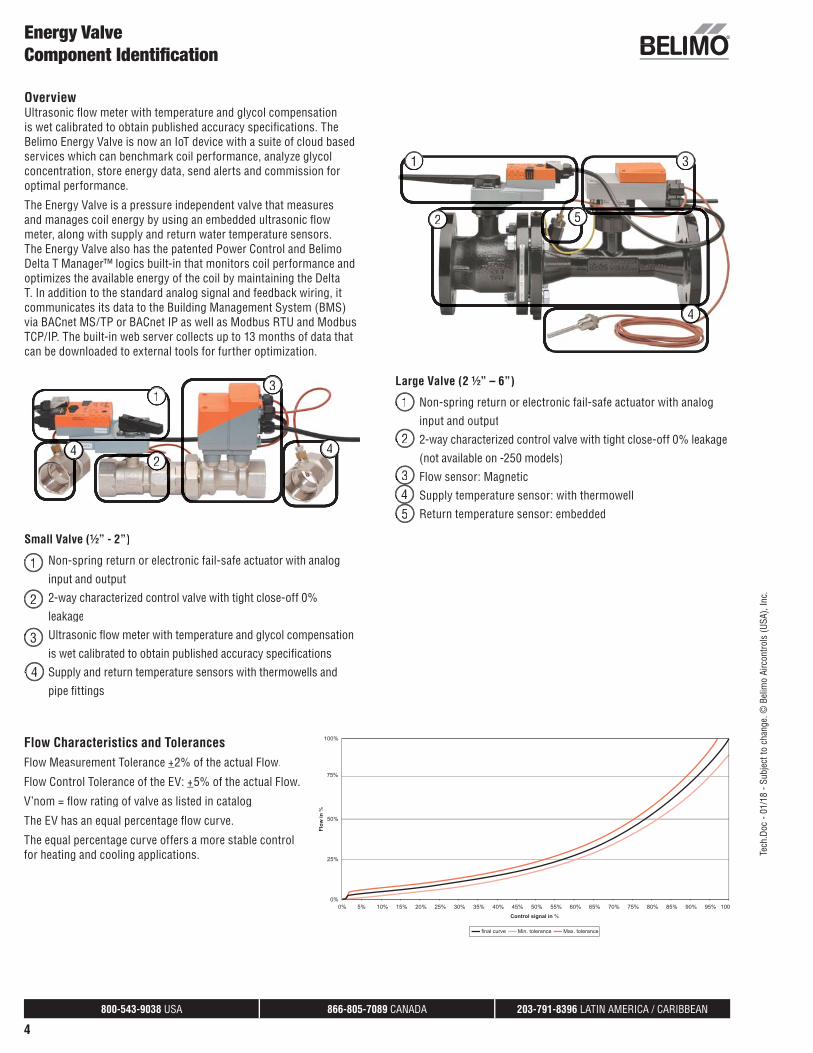
OverviewUltrasonic fl ow meter with temperature and glycol compensationis wet calibrated to obtain published accuracy specifi cations. TheBelimo Energy Valve is now an IoT device with a suite of cloud basedservices which can benchmark coil performance, analyze glycolconcentration, store energy data, send alerts and commission foroptimal performance.
The Energy Valve is a pressure independent valve that measures and manages coil energy by using an embedded ultrasonic fl owmeter, along with supply and return water temperature sensors.The Energy Valve also has the patented Power Control and BelimoDelta T Manager™ logics built-in that monitors coil performance andoptimizes the available energy of the coil by maintaining the Delta T. In addition to the standard analog signal and feedback wiring, itcommunicates its data to the Building Management System (BMS) via BACnet MS/TP or BACnet IP as well as Modbus RTU and Modbus TCP/IP. The built-in web server collects up to 13 months of data that can be downloaded to external tools for further optimization.
1
2
3
44
Small Valve (½” - 2”)
• Non-spring return or electronic fail-safe actuator with analog
input and output
• 2-way characterized control valve with tight close-off 0%
leakage
• Ultrasonic fl ow meter with temperature and glycol compensation
is wet calibrated to obtain published accuracy specifi cations
• Supply and return temperature sensors with thermowells and
pipe fi ttings
Large Valve (2 ½” – 6”)
Non-spring return or electronic fail-safe actuator with analog
input and output
• 2-way characterized control valve with tight close-off 0% leakage
(not available on -250 models)
• Flow sensor: Magnetic
Supply temperature sensor: with thermowell
• Return temperature sensor: embedded
• 1
• 2
• 3
• 4
• 1
• 2
• 3• 4• 5
1
2
3
4
5
Flow Characteristics and TolerancesFlow Measurement Tolerance +2% of the actual Flow.
Flow Control Tolerance of the EV: +5% of the actual Flow.
V’nom = fl ow rating of valve as listed in catalog
The EV has an equal percentage fl ow curve.
The equal percentage curve offers a more stable control for heating and cooling applications.

800-543-9038 USA 866-805-7089 CANADA 203-791-8396 LATIN AMERICA / CARIBBEAN
5
Tech
.Doc
- 01
/18
- Sub
ject
to c
hang
e. ©
Bel
imo
Airc
ontro
ls (U
SA),
Inc.
The Energy Valve is an energy metering pressure independent characterized control valve that optimizes, documents and proves water coil performance.
FeaturesIoT Capability - Advanced System Optimization through cloud technology.
Glycol Monitoring - A feature exclusive to the Energy valve that provides the abilityto determine glycol content. By utilizing advanced algorithms in the Belimo designedultrasonic fl ow meter the glycol concentration can be provided. A minimum fl ow rate isprovided automatically if glycol content is too low which will prevent system freezing anddamage.
Flow Control / Pressure Independent - Accurate and automatic pressure independent fl ow control is achieved through the Energy Valve’s electromagnetic or ultrasonic fl ow sensor. The valve reacts to changes in pressure and modulates the actuator to maintain the fl ow setpoint.
Power Control - Allows you to set your heat transfer thermal power output to a maximum full load value with a linear heat transfer response throughout the entireload range. Coil and valve characteristics become irrelevant making the valve pressure and temperature independent.
True Flow - Unlike mechanical pressure independent valves that provide an approximated/calculated fl ow, the built-in electronic fl ow meter provides True Flow as feedback. Flow verifi cation is simple, troubleshooting is fast, and True Flow can be shared with the DDC system.
Dynamic Balancing - Coil is always perfectly balanced without the need for any time consuming balancing effort regardless of hydronic pressure variations or piping changes. Occupant comfort is improved by eliminating hunting and cycling of the valve that eliminates overfl ows and increases equipment longevity.
Energy Meter - Thermal heat transfer energy data is transparent allowing users the ability to see and document system performance during commissioning and over time. Energy waste is identifi ed and eliminated by modifying settings within the Energy Valve logic and by sharing the data with an Energy Management Control System.
Belimo Delta T Manager™ - Continuously monitors the coil T and compares this value with the dT setpoint. If the actual T is below the dT setpoint, the logicwill reduce valve fl ow to bring T back to the setpoint.
Live Data - Data such as delta T, fl ow, valve position, and heat transfer thermal power can be viewed live or shared with the DDC system. Commissioning,troubleshooting, and integration to DDC systems is fast and reliable.
Coil History - Live data as well as many other performance parameters are stored for up to 13 months in the actuator. Belimo provides an Excel based DataAnalysis Tool that is free to download. This data allows operators to benchmark and better understand system performance.
Characterized Control Valve (CCV) Technology* - High rangeability delivers superior light load fl ow control, eliminates “opening jump”, and on-off control response at low fl ow. The ball valve is self-cleaning which eliminates debris buildup and clogging.
Zero Leakage / High Close-off* - Wasteful “ghost energy” fl ow losses are eliminated which saves energy cost and improves occupant comfort.
Low Minimum Pressure Drop - Valve fl ow output is pressure independent with as low as 1 psid operating differential pressure. Designers can now size valves andpumps to operate at 3 - 4 psid that reduces pump head and allows for smaller pump selection.
Field Confi guration - Small hand held tool or web browser users now can make fi eld adjustments. Additional system integration and control with Modbus RTUand TCP/IP proving users with a wide range of options for integration including, BTL listed BACnet MSTP and BACnet IP, Analog and Belimo MP bus, BACnet MS/TP or IP.
Commissioning Report - Provides a report of the valve settings for historical records and operation allowing for a confi rmation of valve operation and set up. Save and reload setting: easily save settings from one valve confi guration and load in another allowing for fast and accurate integration.
5-Year Warranty - Without cloud integration.
7-Year Warranty - With connection to cloud.**
*Not available on -250 models.
**The following provision supplements the applicable Terms and Conditions of Sale for the Energy Valve 3.0. The 5-year warranty foreseen in the Terms and Conditions of Sale shall be replaced by a 7-year warranty, provided the following conditions are fulfi lled:
• The Cloud-connection on the respective BELIMO device is activated• The respective BELIMO device has been allocated to a Cloud-Account • At the time of the warranty claim the connection ratio between the BELIMO device and the BELIMO-Cloud is at least 90% (the connection ratio is
determined by the amount of hours of Cloud-connection of the BELIMO device divided by its operating hours).
PressureFlow
BELIMOENERGYVALVE
Energy Valve Features

800-543-9038 USA 866-805-7089 CANADA 203-791-8396 LATIN AMERICA / CARIBBEAN
6
Tech
.Doc
- 01
/18
- Sub
ject
to c
hang
e. ©
Bel
imo
Airc
ontro
ls (U
SA),
Inc.
Energy Valve Set Up Options- Default Ordering Example
Energy Valve Nomenclature
EV 250S -127 +ARB 24 -EV
Energy
Valve
NPT 2-way
(½” to 2”)
Flanged 2-way
(2½” to 6”)
Valve Size
050 = ½”
075 = ¾”
100 = 1”
125 = 1¼”
150 = 1½”
200 = 2”
250 = 2½”
300 = 3”
400 = 4”
500 = 5”
600 = 6”
S = Stainless
Steel Ball and
Stem
Flow Rate
1.65 - 713 GPM
Refer to valve
pages for a
full list
Pressure
Rating
Blank = ANSI 125
-250 = ANSI 250
Actuator Type
Non-Spring Return
LRB, LRX
NRB, NRX
ARB, ARX
GRB, GRX
EVX*
Electronic Fail-Safe
AKRB, AKRX
GKRB, GKRX
AVKX*
Power
Supply
24 = 24 VAC/DC
EV = ½” to 6” -L = 2½”
to 3”*
-B = 4”
to 6”*
-G = Glycol
Measurement
The Energy Valve can be ordered two different ways once the valve and actuator are selected in the
valve section starting on page 6-10.
1. Default. The product is shipped already programmed with the default settings below. The default
models use actuators that contain a B in the actuator part number i.e. EV250S-127+ARB24-EV.
2. Programmed. The product will ship to the specifi c settings ordered by the customer using the
Program Codes in steps 1 through 7 on the next page. The programmed models use actuators that
contain an X in the actuator part number i.e. EV250S-127+ARX24-EV.
NOTE: If no specifi c settings are selected, the product will ship with the default settings below.
DEFAULT SETTINGS
Maximum FlowInstallation
PositionDelta T Manager Delta T Setpoint Actuator Setup
Control and
Feedback Signal
Maximum fl ow of
the valve
Return Off 10°F [5.6°C] Non-Spring Return-
Normally Closed (NC)
Control Signal (Y)
DC 2 to 10V
Electronic Fail-Safe-
Normally Closed (NC) /
Fail Closed (FC)
Feedback Signal (U)
DC 2 to 10V
COMPLETE DEFAULT ORDERING EXAMPLE:
EV250S-127+ARB24-EV
*ANSI 250 models only
“X” models are customizable.Refer to page 6-3 for programming options.
800-543-9038 USA 866-805-7089 CANADA 203-791-8396 LATIN AMERICA / CARIBBEAN
7
Tech
.Doc
- 01
/18
- Sub
ject
to c
hang
e. ©
Bel
imo
Airc
ontro
ls (U
SA),
Inc.
Energy Valve Set Up OptionsProgrammed Ordering Example
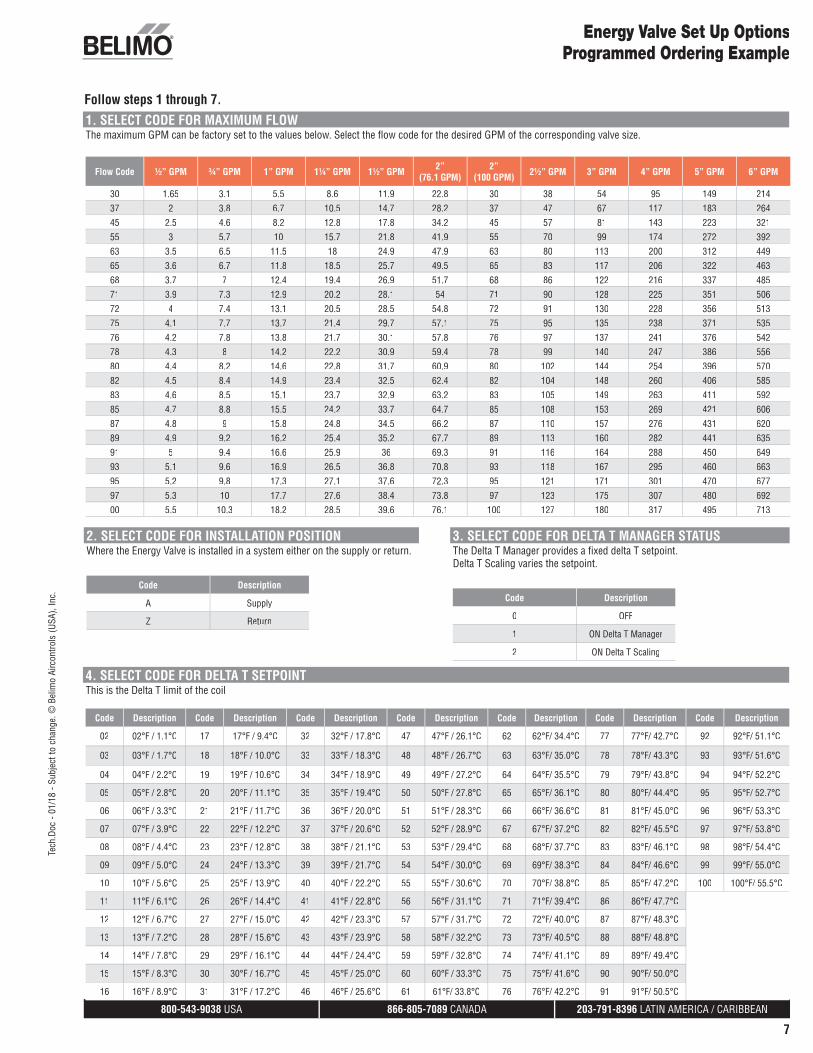
2. SELECT CODE FOR INSTALLATION POSITIONWhere the Energy Valve is installed in a system either on the supply or return.
Code Description
A Supply
Z Return
3. SELECT CODE FOR DELTA T MANAGER STATUSThe Delta T Manager provides a fi xed delta T setpoint. Delta T Scaling varies the setpoint.
Code Description
0 OFF
1 ON Delta T Manager
2 ON Delta T Scaling
4. SELECT CODE FOR DELTA T SETPOINTThis is the Delta T limit of the coil
Code Description Code Description Code Description Code Description Code Description Code Description Code Description
02 02°F / 1.1°C 17 17°F / 9.4°C 32 32°F / 17.8°C 47 47°F / 26.1°C 62 62°F/ 34.4°C 77 77°F/ 42.7°C 92 92°F/ 51.1°C
03 03°F / 1.7°C 18 18°F / 10.0°C 33 33°F / 18.3°C 48 48°F / 26.7°C 63 63°F/ 35.0°C 78 78°F/ 43.3°C 93 93°F/ 51.6°C
04 04°F / 2.2°C 19 19°F / 10.6°C 34 34°F / 18.9°C 49 49°F / 27.2°C 64 64°F/ 35.5°C 79 79°F/ 43.8°C 94 94°F/ 52.2°C
05 05°F / 2.8°C 20 20°F / 11.1°C 35 35°F / 19.4°C 50 50°F / 27.8°C 65 65°F/ 36.1°C 80 80°F/ 44.4°C 95 95°F/ 52.7°C
06 06°F / 3.3°C 21 21°F / 11.7°C 36 36°F / 20.0°C 51 51°F / 28.3°C 66 66°F/ 36.6°C 81 81°F/ 45.0°C 96 96°F/ 53.3°C
07 07°F / 3.9°C 22 22°F / 12.2°C 37 37°F / 20.6°C 52 52°F / 28.9°C 67 67°F/ 37.2°C 82 82°F/ 45.5°C 97 97°F/ 53.8°C
08 08°F / 4.4°C 23 23°F / 12.8°C 38 38°F / 21.1°C 53 53°F / 29.4°C 68 68°F/ 37.7°C 83 83°F/ 46.1°C 98 98°F/ 54.4°C
09 09°F / 5.0°C 24 24°F / 13.3°C 39 39°F / 21.7°C 54 54°F / 30.0°C 69 69°F/ 38.3°C 84 84°F/ 46.6°C 99 99°F/ 55.0°C
10 10°F / 5.6°C 25 25°F / 13.9°C 40 40°F / 22.2°C 55 55°F / 30.6°C 70 70°F/ 38.8°C 85 85°F/ 47.2°C 100 100°F/ 55.5°C
11 11°F / 6.1°C 26 26°F / 14.4°C 41 41°F / 22.8°C 56 56°F / 31.1°C 71 71°F/ 39.4°C 86 86°F/ 47.7°C
12 12°F / 6.7°C 27 27°F / 15.0°C 42 42°F / 23.3°C 57 57°F / 31.7°C 72 72°F/ 40.0°C 87 87°F/ 48.3°C
13 13°F / 7.2°C 28 28°F / 15.6°C 43 43°F / 23.9°C 58 58°F / 32.2°C 73 73°F/ 40.5°C 88 88°F/ 48.8°C
14 14°F / 7.8°C 29 29°F / 16.1°C 44 44°F / 24.4°C 59 59°F / 32.8°C 74 74°F/ 41.1°C 89 89°F/ 49.4°C
15 15°F / 8.3°C 30 30°F / 16.7°C 45 45°F / 25.0°C 60 60°F / 33.3°C 75 75°F/ 41.6°C 90 90°F/ 50.0°C
16 16°F / 8.9°C 31 31°F / 17.2°C 46 46°F / 25.6°C 61 61°F/ 33.8°C 76 76°F/ 42.2°C 91 91°F/ 50.5°C
Follow steps 1 through 7.
1. SELECT CODE FOR MAXIMUM FLOWThe maximum GPM can be factory set to the values below. Select the fl ow code for the desired GPM of the corresponding valve size.
Flow Code ½” GPM ¾” GPM 1” GPM 1¼” GPM 1½” GPM 2” (76.1 GPM)
2” (100 GPM) 2½” GPM 3” GPM 4” GPM 5” GPM 6” GPM
30 1.65 3.1 5.5 8.6 11.9 22.8 30 38 54 95 149 21437 2 3.8 6.7 10.5 14.7 28.2 37 47 67 117 183 26445 2.5 4.6 8.2 12.8 17.8 34.2 45 57 81 143 223 32155 3 5.7 10 15.7 21.8 41.9 55 70 99 174 272 39263 3.5 6.5 11.5 18 24.9 47.9 63 80 113 200 312 44965 3.6 6.7 11.8 18.5 25.7 49.5 65 83 117 206 322 46368 3.7 7 12.4 19.4 26.9 51.7 68 86 122 216 337 48571 3.9 7.3 12.9 20.2 28.1 54 71 90 128 225 351 50672 4 7.4 13.1 20.5 28.5 54.8 72 91 130 228 356 51375 4.1 7.7 13.7 21.4 29.7 57.1 75 95 135 238 371 53576 4.2 7.8 13.8 21.7 30.1 57.8 76 97 137 241 376 54278 4.3 8 14.2 22.2 30.9 59.4 78 99 140 247 386 55680 4.4 8.2 14.6 22.8 31.7 60.9 80 102 144 254 396 57082 4.5 8.4 14.9 23.4 32.5 62.4 82 104 148 260 406 58583 4.6 8.5 15.1 23.7 32.9 63.2 83 105 149 263 411 59285 4.7 8.8 15.5 24.2 33.7 64.7 85 108 153 269 421 60687 4.8 9 15.8 24.8 34.5 66.2 87 110 157 276 431 62089 4.9 9.2 16.2 25.4 35.2 67.7 89 113 160 282 441 63591 5 9.4 16.6 25.9 36 69.3 91 116 164 288 450 64993 5.1 9.6 16.9 26.5 36.8 70.8 93 118 167 295 460 66395 5.2 9.8 17.3 27.1 37.6 72.3 95 121 171 301 470 67797 5.3 10 17.7 27.6 38.4 73.8 97 123 175 307 480 69200 5.5 10.3 18.2 28.5 39.6 76.1 100 127 180 317 495 713
800-543-9038 USA 866-805-7089 CANADA 203-791-8396 LATIN AMERICA / CARIBBEAN
8
Tech
.Doc
- 01
/18
- Sub
ject
to c
hang
e. ©
Bel
imo
Airc
ontro
ls (U
SA),
Inc.
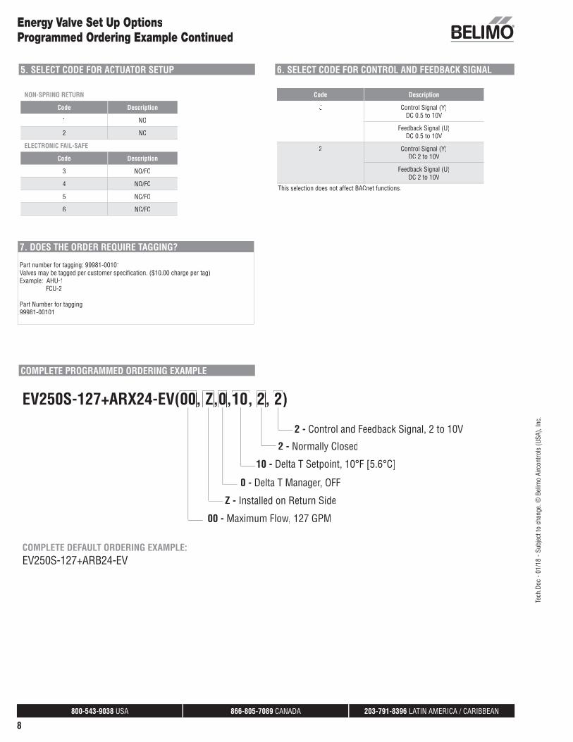
Energy Valve Set Up OptionsProgrammed Ordering Example Continued
5. SELECT CODE FOR ACTUATOR SETUP
NON-SPRING RETURN
Code Description
1 NO
2 NC
ELECTRONIC FAIL-SAFE
Code Description
3 NO/FO
4 NO/FC
5 NC/FO
6 NC/FC
6. SELECT CODE FOR CONTROL AND FEEDBACK SIGNAL
Code Description
Control Signal (Y)DC 0.5 to 10V
Feedback Signal (U)DC 0.5 to 10V
2 Control Signal (Y)DC 2 to 10V
Feedback Signal (U)DC 2 to 10V
7. DOES THE ORDER REQUIRE TAGGING?
Part number for tagging: 99981-00101Valves may be tagged per customer specifi cation. ($10.00 charge per tag)Example: AHU-1 FCU-2
Part Number for tagging:99981-00101
COMPLETE PROGRAMMED ORDERING EXAMPLE
EV250S-127+ARX24-EV(00, Z,0,10, 2, 2)00 Z 0 10 2 2
2 - Control and Feedback Signal, 2 to 10V
2 - Normally Closed
10 - Delta T Setpoint, 10°F [5.6°C]
0 - Delta T Manager, OFF
Z - Installed on Return Side
00 - Maximum Flow, 127 GPM
COMPLETE DEFAULT ORDERING EXAMPLE:EV250S-127+ARB24-EV
This selection does not affect BACnet functions.

800-543-9038 USA 866-805-7089 CANADA 203-791-8396 LATIN AMERICA / CARIBBEAN
9
Tech
.Doc
- 01
/18
- Sub
ject
to c
hang
e. ©
Bel
imo
Airc
ontro
ls (U
SA),
Inc.
Mode of OperationThe Energy Valve is an energy metering pressure independentcontrol valve that optimizes, documents, and proves water coil performance.
Product FeaturesMeasures Energy: using its built-in electronic fl ow sensor andsupply and return temperature sensors.Controls Power: with its Power Control logic, providing linearheat transfer regardless of temperature and pressure variations.Manages Delta T: by solving Low Delta T Syndrome. In addition, it reduces pumping costs while increasing chiller/boiler effi ciencyby optimizing coil effi ciency.
Actuator Specifi cationsControl type modulatingManual override LR, NR, AR, GR, AKR, GKR, EV, AVKElectrical connection 3 ft. [1 m] cable with ½” conduit fi tting
Valve Specifi cationsService chilled or hot water, 60% glycol (open loop and steam not allowed)Flow characteristic equal percentage/linearControllable fl ow range 75°Action stem up - open A to ABSizes ½”, ¾”, 1”, 1¼”, 1½”, 2”, 2½’’, 3’’, 4’’, 5’’, 6’’End fi tting NPT female (½”- 2”) pattern to mate with ANSI 125 or 250 flange (e 2½”- 6”)Materials Body Valve forged brass, nickel plated (½”- 2”) cast iron - GG25 (2½”- 6”) Sensor housing forged brass, nickel plated (½”- 2”) ductile iron - GGG50 (2½”- 6”) Ball stainless steel Stem stainless steel Plug stainless steel (-250) Seats Tefl on® PTFE, stainless steel (-250) Characterizing disc Tefzel® (½”- 2”) stainless steel (2½”- 6”) Stem packing EPDM (lubricated), NLP (-250)Media temp range 14°F to 250°F [-10°C to +120°C], 39°F to 250°F [4°C to 120°C](EV200S-1000)Body pressure rating 360 psi (½”- 2”), ANSI 125, Class B (2½”- 6”) ANSI 250 (2½”-6”) (-250)Close-off pressure 200 psi (½”- 2”), 100 psi (2½”- 6”), varies by size (-250)Differential pressurerange (ΔP) see application pagesLeakage 0%, ANSI Class IV (-250)Inlet length to meetspecifi ed measurementaccuracy 5x nominal pipe size (NPS)Communication BACnet IP, BACnet MS/TP, listed by BTL, web server, Modbus RTU/IP, Belimo MP-BusRemote temperaturesensor length
½”- 2” 2 ft. 7.5 in. [0.8 m] short, 9.8 ft. [3 m] long 2½”- 6” 32.8 ft. [10 m]
Equal PercentageCharacteristic
Control Valve Product RangeEnergy Valve Product Range
EV
Valve Nominal Size Type Suitable Actuators
GPM Range Inches DN [mm] 2-way Non-Spring
ReturnElectronic Fail-Safe
NPT
1.65 - 5.5* ½ 15 EV050S-055
LRB(
X)24
-EV(
-G)
AKRB
(X)2
4-EV
(-G)
3.1 - 10.3* ¾ 20 EV075S-103
5.5 - 18.2* 1 25 EV100S-182
8.6 - 28.5* 1¼ 32 EV125S-285
NRB(
X)24
-EV(
-G)
11.9 - 39.6* 1½ 40 EV150S-396
22.8 - 76.1* 2 50 EV200S-761
ARB(
X)24
-EV(
-G)
30-100* 2 50 EV200S-1000**
Flan
ged
ANSI
125
38 - 127* 2½ 65 EV250S-127
54 - 180* 3 80 EV300S-180
95 - 317* 4 100 EV400S-317
GRB(
X)24
-EV
GKRB
(X)2
4-EV
149 - 495* 5 125 EV500S-495
214 - 713* 6 150 EV600S-713
Flan
ged
ANSI
250
38 - 127* 2½ 65 EV250S-127-250
EVX2
4-EV
-L
AVKX
24-E
V-L
54 - 180* 3 80 EV300S-180-250
95 - 317* 4 100 EV400S-317-250
EVX2
4-EV
-B
AVKX
24-E
V-B
149 - 495* 5 125 EV500S-495-250
214 - 713* 6 150 EV600S-713-250
*V’nom = Maximum fl ow for each valve body size.** Media temperature range is 39°F to 250°F [4 °C to 120°C]

800-543-9038 USA 866-805-7089 CANADA 203-791-8396 LATIN AMERICA / CARIBBEAN
10
Tech
.Doc
- 01
/18
- Sub
ject
to c
hang
e. ©
Bel
imo
Airc
ontro
ls (U
SA),
Inc.
Energy ValvesOperation/Installation
FUNCTIONALITYThe Energy Valve offers different operating modes which can be selected using the Web View or ZTH US.
*Feedback sig
Delta T Manager OFF Delta T Manager ON
Posi
tion
Cont
rol
Y Signal controls the valve position.
Position ControlThe Energy Valve works as a normalpressure dependent valve. Theactuator is positioned based on the DDC control signal.
T2
T1
Y Signal controls the valve position as long as the ΔT is above the ΔT setpoint.
Position Control + Delta T ManagerThe Energy Valve works as a pressuredependent valve. If the measured T is lowerthan the T setpoint the fl ow will be reduced by the Delta T Manager logic to achieve the setpoint, regardless of the control signal Y.
Note: In position control, only T Manager can beselected, T Manager Scaling will not be available.
Flow
Con
trol
Y Signal controls the flow.
Pressure Independent Flow ControlThe Energy Valve works as an ePIV(Electronic Pressure IndependentValve). The valve reacts to anychange in pressure and modulatesthe actuator to maintain the fl ow setpoint based on the DDC control signal.
T2
T1
Y Signal controls the flow as long as the ΔT is above the ΔT setpoint.
Pressure Independent Flow Control+ Delta T ManagerThe Energy Valve works as an ePIV. However, if the measured T is lower than the Tsetpoint, the fl ow will be reduced by the DeltaT Manager logic to achieve the T setpoint, regardless of the control signal Y.
Pow
er C
ontr
ol
T2
T1
Y Signal controls the coil thermal power setpoint (BTU/hr or kW).
Power ControlThe Energy Valve adjusts fl ow to maintain the thermal power setpoint. If the measured coil power is belowsetpoint, fl ow will be increased. Ifthe measured coil power is abovesetpoint, fl ow will be decreased aslong as the defi ned V’max is notexceeded.
T2
T1
Y Signal controls the thermal power setpoint as long as the ΔT is above the ΔT setpoint.
Power Control + Delta T ManagerThe Energy Valve adjusts fl ow to maintainthe thermal power setpoint. If the measured coil power is below setpoint, fl ow will beincreased. If the measured coil power is above setpoint, fl ow will be decreased as long as the defi ned V’max is not exceeded. If themeasured T is lower than the T setpoint,fl ow will be reduced by the Delta T Manager logic and will override the thermal power control setpoint.
SET-UP - Specify Upon Ordering
2-WAY VALVE
NON-
SPRI
NG R
ETUR
NST
AYS
IN L
AST
POSI
TION
LRX...SeriesNRX...Series ARX...SeriesGRX...SeriesEVX...Series
NC: Normally Closed-valve will open as voltageincreases.
NO: Normally Open-valve will close as voltageincreases.
ELEC
TRON
IC F
AIL-
SAFE
STAY
S IN
FAI
L-SA
FE P
OSIT
ION
AKRX...SeriesGKRX...SeriesAVKX...Series
NO/FO Valve: NormallyOpen-valve will close asvoltage increases.Fail Action: Will fail openupon power loss.
NO/FC Valve: NormallyOpen-valve will close asvoltage increases.Fail Action: Will failclosed upon power loss.
NC/FO Valve: NormallyClosed-valve will open asvoltage increases. Fail Action: Will fail openupon power loss.
NC/FC Valve: NormallyClosed-valve will openas voltage increases. Fail Action: Will failclosed upon powerloss.
Note: When in Power Control mode, a failure in any temperature sensor will cause the valve to operate in Flow Control mode. A failure in the fl ow sensor, will cause thevalve to operate in Position Control mode. When the situation is rectifi ed, the valve will revert to its Control Mode setting.
800-543-9038 USA 866-805-7089 CANADA 203-791-8396 LATIN AMERICA / CARIBBEAN
11
Tech
.Doc
- 01
/18
- Sub
ject
to c
hang
e. ©
Bel
imo
Airc
ontro
ls (U
SA),
Inc.
5 x Nominal Pipe Size (NPS)
Energy Valve Installation
Piping
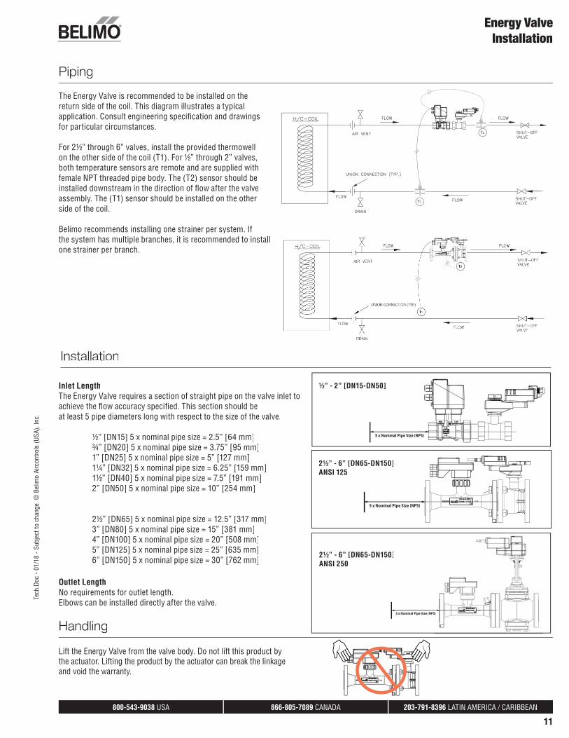
The Energy Valve is recommended to be installed on thereturn side of the coil. This diagram illustrates a typicalapplication. Consult engineering specifi cation and drawings for particular circumstances.
For 2½” through 6” valves, install the provided thermowellon the other side of the coil (T1). For ½” through 2” valves, both temperature sensors are remote and are supplied with female NPT threaded pipe body. The (T2) sensor should be installed downstream in the direction of fl ow after the valveassembly. The (T1) sensor should be installed on the other side of the coil.
Belimo recommends installing one strainer per system. Ifthe system has multiple branches, it is recommended to install one strainer per branch.
Installation
Inlet LengthThe Energy Valve requires a section of straight pipe on the valve inlet to achieve the fl ow accuracy specifi ed. This section should be at least 5 pipe diameters long with respect to the size of the valve.
½” [DN15] 5 x nominal pipe size = 2.5” [64 mm]¾” [DN20] 5 x nominal pipe size = 3.75” [95 mm]1” [DN25] 5 x nominal pipe size = 5” [127 mm]1¼” [DN32] 5 x nominal pipe size = 6.25” [159 mm]1½” [DN40] 5 x nominal pipe size = 7.5” [191 mm]2” [DN50] 5 x nominal pipe size = 10” [254 mm]
2½” [DN65] 5 x nominal pipe size = 12.5” [317 mm]3” [DN80] 5 x nominal pipe size = 15” [381 mm]4” [DN100] 5 x nominal pipe size = 20” [508 mm]5” [DN125] 5 x nominal pipe size = 25” [635 mm]6” [DN150] 5 x nominal pipe size = 30” [762 mm]
Outlet LengthNo requirements for outlet length.Elbows can be installed directly after the valve.
5 x Nominal Pipe Size (NPS)
5 x Nominal Pipe Size (NPS)
½” - 2” [DN15-DN50]
2½” - 6” [DN65-DN150]ANSI 125
Handling
Lift the Energy Valve from the valve body. Do not lift this product by the actuator. Lifting the product by the actuator can break the linkage and void the warranty.
2½” - 6” [DN65-DN150]ANSI 250

800-543-9038 USA 866-805-7089 CANADA 203-791-8396 LATIN AMERICA / CARIBBEAN
12
Tech
.Doc
- 01
/18
- Sub
ject
to c
hang
e. ©
Bel
imo
Airc
ontro
ls (U
SA),
Inc.
Remote Sensor Installation:
½” [DN 15] to 2” [DN 50]Two remote sensors with female NPT pipe bodies are provided with the Energy Valve and must be installed on opposite sides of the coil.Temperature Sensor 1 (T1) is equipped with a longer sensor cable than Temperature Sensor 2 (T2). It is recommended that the Energy Valve is installed on the return side of the coil. The T1 sensor will be on the supply side and the T2 sensor will be on the return. The T2 sensor should be installed upstream in the direction of the fl ow after the valve.
2½” [DN 65] to 6” [DN 150]A thermowell is provided with the remote temperature sensor. The well should be installed on the pipe prior to installing the remote temperaturesensor. The remote temperature sensor should be installed on the opposite pipe entering the coil from where the Energy Valve is installed. A ½”NPT female union should be welded on the pipe to allow the installation of the thermowell. The Energy Valve is equipped with a 32 ft. [10 m] cablefor the remote sensor. If a shorter remote sensor cable is required, the cable is also available in the following sizes: 4.9 ft. [1.5 m], 9.8 ft. [3 m], or 16.4 ft. [5 m]. Order the appropriate size for the application.
Note: If a different sensor with a different cable length has been installed, the change must be applied to the Energy Valve Web View Settings. Refer to Web View Settings table on page 33.Do not cut sensor cables, this will produce inaccurate data. Belimo offers different sensor cabling lengths options.
Energy Valve Installation
Remote Well Installation Dimensional Parameters
IN DN [mm] EL ET L max.
2 ½ 65 3.66” [93] 2.36” [60] 1.18” [30]
3 80 3.66” [93] 2.36” [60] 1.18” [30]
4 100 3.66” [93] 2.36” [60] 1.18” [30]
5 125 3.66” [93] 2.36” [60] 1.18” [30]
6 150 3.66” [93] 2.36” [60] 1.18” [30]
Female NPT Dimensions
IN DN [mm] A B C D E
½ 15 ½” NPT 0.6” 2.06” 0.62” 0.76”
¾ 20 ¾” NPT 0.65” 2.24” 0.82” 0.63”
1 25 1” NPT 0.76” 2.54” 1.02” 0.53”
1¼ 32 1¼” NPT 0.85” 2.77” 1.29” 1.61”
1½ 40 1½” NPT 0.87” 2.77” 1.61” 1.77”
2 50 2” NPT 1.04” 3.16” 2.00” 2.00”
800-543-9038 USA 866-805-7089 CANADA 203-791-8396 LATIN AMERICA / CARIBBEAN
13
Energy Valve Installation
Actuator, Temperature & Flow Sensor Replacement
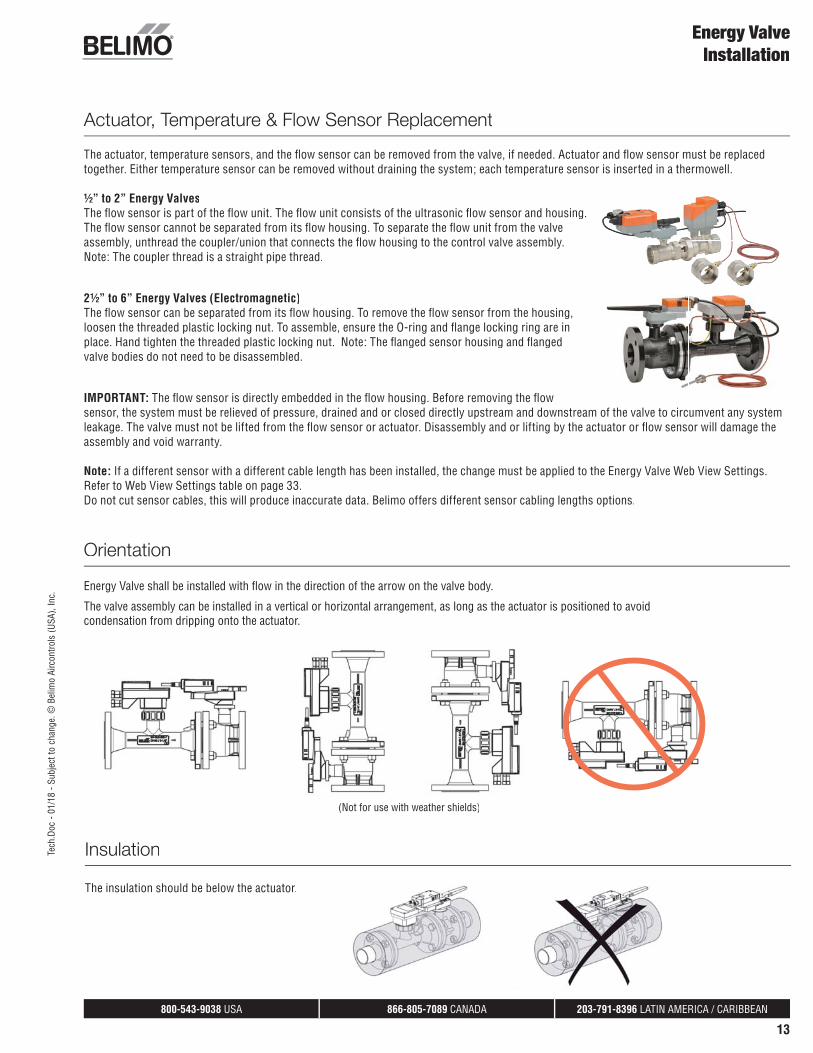
The actuator, temperature sensors, and the fl ow sensor can be removed from the valve, if needed. Actuator and fl ow sensor must be replacedtogether. Either temperature sensor can be removed without draining the system; each temperature sensor is inserted in a thermowell.
½” to 2” Energy ValvesThe fl ow sensor is part of the fl ow unit. The fl ow unit consists of the ultrasonic fl ow sensor and housing.The fl ow sensor cannot be separated from its fl ow housing. To separate the fl ow unit from the valveassembly, unthread the coupler/union that connects the fl ow housing to the control valve assembly.Note: The coupler thread is a straight pipe thread.
2½” to 6” Energy Valves (Electromagnetic)The fl ow sensor can be separated from its fl ow housing. To remove the fl ow sensor from the housing,loosen the threaded plastic locking nut. To assemble, ensure the O-ring and fl ange locking ring are inplace. Hand tighten the threaded plastic locking nut. Note: The fl anged sensor housing and fl angedvalve bodies do not need to be disassembled.
IMPORTANT: The fl ow sensor is directly embedded in the fl ow housing. Before removing the fl ow sensor, the system must be relieved of pressure, drained and or closed directly upstream and downstream of the valve to circumvent any systemleakage. The valve must not be lifted from the fl ow sensor or actuator. Disassembly and or lifting by the actuator or fl ow sensor will damage theassembly and void warranty.
Note: If a different sensor with a different cable length has been installed, the change must be applied to the Energy Valve Web View Settings. Refer to Web View Settings table on page 33.Do not cut sensor cables, this will produce inaccurate data. Belimo offers different sensor cabling lengths options.
Energy Valve shall be installed with fl ow in the direction of the arrow on the valve body.
The valve assembly can be installed in a vertical or horizontal arrangement, as long as the actuator is positioned to avoid condensation from dripping onto the actuator.
(Not for use with weather shields)
Orientation
Insulation
The insulation should be below the actuator.
Tech
.Doc
- 01
/18
- Sub
ject
to c
hang
e. ©
Bel
imo
Airc
ontro
ls (U
SA),
Inc.
800-543-9038 USA 866-805-7089 CANADA 203-791-8396 LATIN AMERICA / CARIBBEAN
14
Tech
.Doc
- 01
/18
- Sub
ject
to c
hang
e. ©
Bel
imo
Airc
ontro
ls (U
SA),
Inc.
Energy Valve Installation
1. Inspect shipping package, valve, linkage, and actuator for physical damage. If shipping damage has occurred, notify appropriate carrier. Do not install.
2. If a replacement, remove existing valve, linkage and actuator from the piping system.
3. If actuator and linkage are removed, they must be reinstalled correctly. The actuator must be rotated so that the valve seats properly close off.
4. Install valve with the proper ports as inlets and outlets. Check that inlet and outlet of 2-way valves are correct. Flow direction arrows must be correct.
5. Blow out all piping and thoroughly clean before valve installation.
6. Clean fl anges with wire brush and rag. Clean pipes, fl anges, and valve fl anges before installation; check for any foreign material that can become lodged in trim components. Strainers should be cleaned after initial startup.
7. Valve must be installed with the stem towards the vertical, not below horizontal. See Orientation on page 15.
8. These valves are designed to be installed between ANSI Class 125/150 fl anges only.
9. -250 models are designed to be installed between ANSI Class 250/300 fl anges only.
10. Carefully follow installation using ANSI piping practices.
Valve should not be used for combustible gas applications. Gas leaks and explosions may result.
Do not install in systems, which exceed the ratings of the valve.
• Avoid installations where valve may be exposed to excessive moisture, corrosive fumes, vibration, high ambient temperatures, elements, or high traffi c areas with potential for mechanical damage.
• Valve assembly location must be within ambient ratings of actuator.If temperature is below -22°F, a heater is required.
• Valve assembly will require heat shielding, thermal isolation, or cooling if combined effect of medium and ambient temperatures – conduction, convection, and radiation– is above 122°F for prolonged periods at the actuator.
• Visual access must be provided. Assembly must be accessible for routine schedule service. Contractor should provide unions for removal from line and isolation valves.
• Avoid excessive stresses. Mechanical support must be provided where reducers have been used and the piping system may have less structural integrity than full pipe sizes.
• Suffi cient upstream piping runs must be provided to ensure proper valve capacity and fl ow response. See installation section for details.
• Life span of valve stems and O-rings is dependent on maintaining non-damaging conditions. Poor water treatment or fi ltration, corrosion, scale, other particulate can result in damage to trim components. A water treatment specialist should be consulted.
• It is not necessary to install one strainer per unit. Belimo recommends installing one strainer per system. If the system has multiple branches, it is recommended to install one strainer per branch.
Installation
800-543-9038 USA 866-805-7089 CANADA 203-791-8396 LATIN AMERICA / CARIBBEAN
15
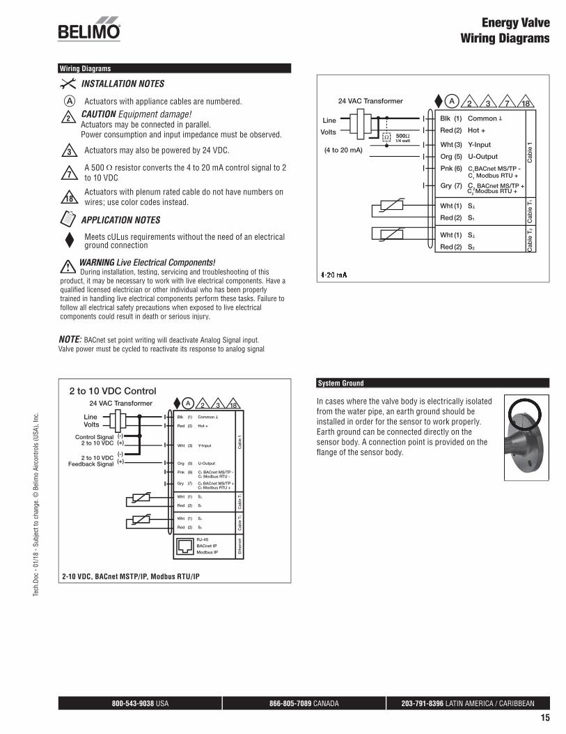
A Actuators with appliance cables are numbered.
2 CAUTION Equipment damage!Actuators may be connected in parallel.Power consumption and input impedance must be observed.
3 Actuators may also be powered by 24 VDC.
7A 500 resistor converts the 4 to 20 mA control signal to 2 to 10 VDC.
18Actuators with plenum rated cable do not have numbers on wires; use color codes instead.
Meets cULus requirements without the need of an electrical ground connection
WARNING Live Electrical Components! During installation, testing, servicing and troubleshooting of this
product, it may be necessary to work with live electrical components. Have aqualified licensed electrician or other individual who has been properlytrained in handling live electrical components perform these tasks. Failure to follow all electrical safety precautions when exposed to live electricalcomponents could result in death or serious injury.
Wiring Diagrams
Energy ValveWiring Diagrams
Blk (1) Common
T
Red (2) Hot +
Wht (1) S T
Red (2) S1
Wht (1) S T
Red (2) S2
24 VAC Transformer
LineVolts
Cab
le T
2C
able
T1
Cab
le 1
Wht (3) Y-Input
Org (5) U-Output
Pnk (6) C1 BACnet MS/TP - C1 Modbus RTU -
2 to 10 VDCFeedback Signal
Control Signal(+)
(+)
(-)
(-)
2 to 10 VDC
A
RJ-45
BACnet IP
Modbus IP Eth
erne
t
Gry (7) C2 BACnet MS/TP + C2 Modbus RTU +
2 3 18
2 to 10 VDC Control
2-10 VDC, BACnet MSTP/IP, Modbus RTU/IP
Blk (1) Common
T
Red (2) Hot +
24 VAC Transformer
Line
Volts
Wht (1) S T
Red (2) S1
Wht (1) S T
Red (2) S2 Cab
le T
2C
able
T1
Cab
le 1Wht (3) Y-Input
Org (5) U-Output
Pnk (6) C1BACnet MS/TP - C1 Modbus RTU +
Gry (7) C2 BACnet MS/TP + C2 Modbus RTU +
(4 to 20 mA)
2 3 18A 7
System Ground
In cases where the valve body is electrically isolatedfrom the water pipe, an earth ground should beinstalled in order for the sensor to work properly. Earth ground can be connected directly on thesensor body. A connection point is provided on thefl ange of the sensor body.
NOTE: BACnet set point writing will deactivate Analog Signal input.Valve power must be cycled to reactivate its response to analog signal.
Tech
.Doc
- 01
/18
- Sub
ject
to c
hang
e. ©
Bel
imo
Airc
ontro
ls (U
SA),
Inc.
800-543-9038 USA 866-805-7089 CANADA 203-791-8396 LATIN AMERICA / CARIBBEAN
16
Flow Control
To set the Energy Valve to Flow Control, set the Control Mode to FlowControl in the Setting area of the Web View, under Confi guration Control Function. Refer Web View settings table on page 33.
Flow Control Application
Use Flow Control to achieve pressure independent valve performance. The valve will react to changes in system pressure to match the fl ow setpoint from the controller.
Flow Control Sequence of Operation
The Energy Valve uses its ultrasonic or magnetic fl ow meter and logic to throttle its characterized control valve (CCV) to maintain the fl ow set point. The valve will respond to the DDC fl ow analog signal except when the current fl ow is within ±5% of the signal.
When the Delta T Manager is enabled, it will activate its logic when the actual T drops 2°F below the dT Setpoint. It does that by throttling the valve close until the dT setpoint is reached. The Energy Valve will resume its normal operation based on the DDC signal when the DDC setpoint drops 5% of V’max below the Delta T Manager’s current fl ow.The Delta T Manager will not operate when the fl ow is below 30% of V’max. In addition, the Delta T Manager minimum fl ow will always be greater than 30% of V’max. The fl ow also needs to be above 30% of v’max for 5 minutes before the Delta T Manager will engage. 30% is the default however for specifi c applications it is possible to operate the Delta T Manager down to 10% of V’nom. This setting is available in Webview on the settings tab under the Delta T Management section.
The Energy Valve is pressure independent over its entire throttling range with available differential pressure from 1-50 psid. When the available differential pressure is less than 5 psid, refer to the Flow Reduction Chart to verify adequate differential pressure to obtain desired V’max.
Power Control
To set the Energy Valve to Power Control, set the Control Mode to Power Control in the Settings area of the Web View, under Confi guration Control Function. Refer to Web View Settings table on page 33.
Power Control Application
Use Power Control to achieve a precise linear power output of the heat exchanger over its operating range. Power Control combines pressure independent valve performance with temperature independent coil
Energy Valve Control Mode Sequence of Operation
performance. The valve will react to changes in system pressure and to changes in water differential temperature to match the power setpoint from the controller.
Power Control / Sequence of Operation
The Energy Valve uses its ultrasonic or magnetic fl ow meter and logic to throttle its characterized control valve to maintain the power set point. The valve will respond to the DDC power analog signal except when the current power is within ±5% of the signal.
When the Delta T Manager is enabled, it will activate its logic when the actual T drops 2°F below the dT setpoint. It does this by throttling the valve close until the dT setpoint is reached. The Energy Valve will resume its normal operation based on the DDC signal; when the DDC setpoint drops 5% of V’max below the Delta T Manager’s current fl ow. The Delta T Manager will not operate when the fl ow is below 30% of V’max. In addition, the Delta T Manager minimum fl ow will always be greater than 30% of V’max. The fl ow also needs to be above 30% of v’max for 5 minutes before the Delta T Manager will engage. 30% is the default however for specifi c applications it is possible to operate the Delta T Manager down to 10% of V’nom. This setting is available in Webview on the settings tab under the Delta T Management section.
With Power Control, the Energy Valve is pressure and temperature independent over its entire throttling range with available differential pressure from 1-50 psid. When the available differential pressure is less than 5 psid, refer to the Flow Reduction table on page 43 to verify adequate differential pressure to obtain desired V’max and associated P’max.
Position Control
To set the Energy Valve to Position Control, set the Control Modeto Position Control in the Settings area of the Web View, under Confi guration Control Function. Refer to the Web View Settings table on page 33.
Position Control Application
Use Position Control to achieve pressure dependent valve performance or to verify control response during installation, maintenance and troubleshooting. The fl ow meter will report actual fl ow at all valve positions.
Tech
.Doc
- 01
/18
- Sub
ject
to c
hang
e. ©
Bel
imo
Airc
ontro
ls (U
SA),
Inc.

800-543-9038 USA 866-805-7089 CANADA 203-791-8396 LATIN AMERICA / CARIBBEAN
17
Position Control Sequence of Operation
The Energy Valve uses position feedback and logic to throttle its characterized control valve to maintain the valve position. The valve will respond to the DDC position analog signal except when the position is within ±5% of the signal.
Delta T Manager Options
To confi gure the Delta T Manager options, set the Confi guration dT-Manager in the Settings area of the Web View. Refer to the Web View Settings table on page 29.
The Delta T Manager monitors the T across the coil. When the T drops below the set point, the Delta T Manager logic throttles the valve close to increase T above the setpoint. When the Delta T Manager is enabled, it will activate its logic when the actual T drops 2°F below the dT Setpoint. It does that by throttling the valve close until the dT setpoint is reached. The Energy Valve will resume its normal operation based on the DDC signal when the DDC setpoint drops 5% of V’max below the Delta T Manager’s current fl ow. The Delta T Manager will not operate when the fl ow is below 30% of V’max. In addition, the Delta T Manager minimum fl ow will always be greater than 30% of V’max. The fl ow also needs to be above 30% of v’max for 5 minutes before the Delta T Manager will engage. Two Delta T Manager options are available: dT Manager and dT Manager Scaling. 30% is the default however for specifi c applications it is possible to operate the Delta T Manager down to 10% of V’nom. This setting is available in Webview on the settings tab under the Delta T Management section.
dT Manager Application
Use dT Manager to assure circuit overfl ow is eliminated below the Delta T Limit Value. Limiting function can be applied to all Control Modes of operation; Flow, Power and Position. Belimo suggests using this mode with changing air mass fl ow rate.
Sequence of Operationq p
This logic when activated will limit the heat exchanger T to a fi xed dT setpoint by reducing valve fl ow. The dT setpoint is equal to the Delta T Limiting Value found in Web View settings.
dT Manager Scaling Application
This limiting function can be applied to all control modes of operation: fl ow and power. Building operators are assured circuit overfl ow is eliminated below the scaled (variable) dT setpoint. Belimo suggests using this mode with changing temperature of the inlet air fl ow or inlet water supply.
Sequence of Operationq p
This logic when activated will limit the heat exchanger T to a scaled (variable) dT setpoint by reducing valve fl ow. The dT setpoint = (Delta T Limit Value /Flow Saturation Value)* (actual fl ow). The Flow Saturation Value found in Web View is a required setting for this logic.
Energy Valve Control Mode Sequence of Operation
Typical Representation of dT Manager Function with Flow Control or Power Control
Typical Representation of dT Manager Scaling Function with Flow Control or Power Control
Graphical dT Manager and dT Manager Scaling Operation
In the graphs shown below, the blue and red data points were captured by allowing the Energy Valve to operate with the Delta T Manager disable and under normal operating conditions for a suffi cient period to collect data ranging from light to full load.
Unrestricted fl ow shown with blue data points occur when the dT manager is inactive. Restricted fl ow shown with red data points would be eliminated when dT Manager is active.
Tech
.Doc
- 01
/18
- Sub
ject
to c
hang
e. ©
Bel
imo
Airc
ontro
ls (U
SA),
Inc.
800-543-9038 USA 866-805-7089 CANADA 203-791-8396 LATIN AMERICA / CARIBBEAN
18
Energy ValveWeb View
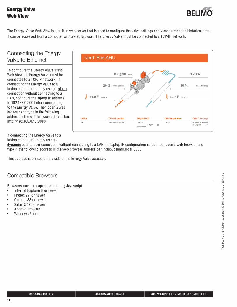
The Energy Valve Web View is a built-in web server that is used to confi gure the valve settings and view current and historical data. It can be accessed from a computer with a web browser. The Energy Valve must be connected to a TCP/IP network.
Connecting the EnergyValve to Ethernet
To confi gure the Energy Valve usingWeb View the Energy Valve must be connected to a TCP/IP network. If connecting the Energy Valve to a laptop computer directly using a staticconnection without connecting to aLAN, confi gure the laptop IP addressto 192.168.0.200 before connecting to the Energy Valve. Then open a webbrowser and type in the followingaddress in the web browser address bar: http://192.168.0.10:8080 p
If connecting the Energy Valve to a laptop computer directly using a dynamicy peer to peer connection without connecting to a LAN, no laptop IP confi guration is required, open a web browser andtype in the following address in the web browser address bar: http://belimo.local:8080p
This address is printed on the side of the Energy Valve actuator.
Compatible Browsers
Browsers must be capable of running Javascript.• Internet Explorer 8 or newer• Firefox 27 or newer• Chrome 33 or newer• Safari 5.17 or newer• Android browser• Windows Phone
Tech
.Doc
- 01
/18
- Sub
ject
to c
hang
e. ©
Bel
imo
Airc
ontro
ls (U
SA),
Inc.

800-543-9038 USA 866-805-7089 CANADA 203-791-8396 LATIN AMERICA / CARIBBEAN
19
Login
Web View User Table Username: Guest Maintenance Admin
Password*: guest belimo Contact Belimo Tech Support
Web View Page
Dashboard Read Read Read
Overview Read Read/Write Read/Write
Override and Trend Control
Read Read/Write Read/Write
Data Log Chart Read Read Read/Write
Settings Read Read Read/Write
Status Read Read/Write Read/Write
Date & Time Settings -- Read/Write Read/Write
IP Settings -- Read/Write Read/Write
Version Information -- Read/Write Read/Write
Mobile Read Read Read/Write
Data Logging Read Read Read/Write
BACnet / MP Settings Read Read Read/Write*Password is case sensitive
Energy ValveWeb View
• Access to the actuator is protected by theuser name and password.
• Three default user types are available tologin. Each user type has different securityrights to the Web View. Refer to Web Viewuser table below.
• Belimo cannot recover IP address. IPaddress can be viewed with ZTH US tool.
Tech
.Doc
- 01
/18
- Sub
ject
to c
hang
e. ©
Bel
imo
Airc
ontro
ls (U
SA),
Inc.

800-543-9038 USA 866-805-7089 CANADA 203-791-8396 LATIN AMERICA / CARIBBEAN
20
The Energy Valve Web View is a graphical user interface accessed via a network or internet to set up, calibrate and change theparameters of the Belimo Energy Valve. The Web View consists of the following page views:
Overview
The overview page allows you to see thesetpoint, fl ow, valve position, glycol percentage if activated, Delta T, and mode of operation. Double click on a heading item to see ahistorical trend of the data.
Data
An analytical view of thehistorical data with the ability to select the type of data toanalyze; primarily used for maintenance and troubleshooting.
This view also, provides key performance indicators In addition this view also hasthe Delta T set point suggestionintegrated. To calculate press the coil characteristic button below x axis.
Energy ValveWeb View
Tech
.Doc
- 01
/18
- Sub
ject
to c
hang
e. ©
Bel
imo
Airc
ontro
ls (U
SA),
Inc.

800-543-9038 USA 866-805-7089 CANADA 203-791-8396 LATIN AMERICA / CARIBBEAN
21
Status
Status provides an error count by type and time elapsed of last occurrence. More details provides additionalinformation with informational buttons on the possiblesolution to the error.
These errors can be reset to zero and should be reset after commissioning to clear any errors that may haveoccurred due to the valve and system not being fully operational.
Settings
Access and adjust the operating settings. Refer toWeb View Settings table on page 33.
Energy ValveWeb View
Tech
.Doc
- 01
/18
- Sub
ject
to c
hang
e. ©
Bel
imo
Airc
ontro
ls (U
SA),
Inc.

800-543-9038 USA 866-805-7089 CANADA 203-791-8396 LATIN AMERICA / CARIBBEAN
22
Date and Time Settings
Provides different ways to set the date and time. It allows thetime to be entered manually, synchronized through a computer, or synchronized with a Time Server.
If BACnet communication is enabled, Local Client Date and Timewill be automated through BACnet.
IP Settings
To confi gure the valve communication on a TCP/IP network. Itallows the valve to have a dynamic IP address (requires an active DHCP server) or a static IP address (requires an IP address,Network Mask and Gateway address from IT manager). TheBroadcast address will be generated automatically.
The DNS Servers are listed here for default. If different arepreferred they will need to be assigned by the customer ITinfrastructure responsible for the Energy Valve installation.
Version Information
Displays current software version.
Energy ValveWeb View
Configuration Options
Tech
.Doc
- 01
/18
- Sub
ject
to c
hang
e. ©
Bel
imo
Airc
ontro
ls (U
SA),
Inc.
800-543-9038 USA 866-805-7089 CANADA 203-791-8396 LATIN AMERICA / CARIBBEAN
23
Energy ValveWeb View
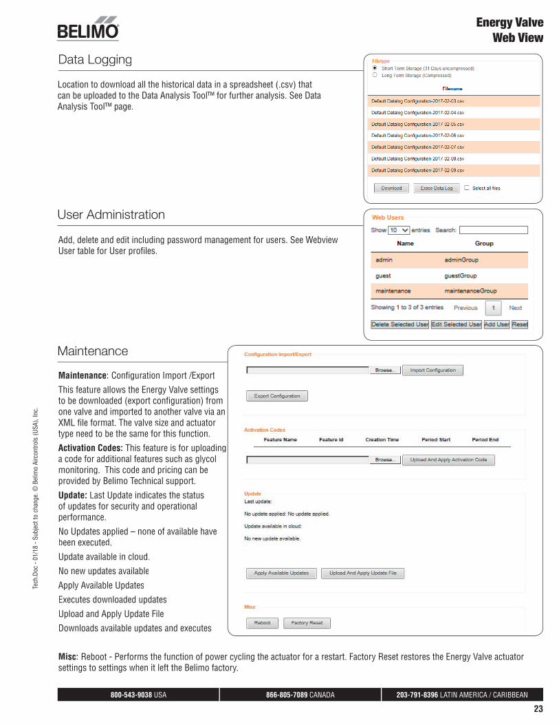
Data Logging
User Administration
Add, delete and edit including password management for users. See WebviewUser table for User profi les.
Location to download all the historical data in a spreadsheet (.csv) thatcan be uploaded to the Data Analysis Tool™ for further analysis. See DataAnalysis Tool™ page.
Maintenance
Maintenance: Confi guration Import /Export
This feature allows the Energy Valve settingsto be downloaded (export confi guration) fromone valve and imported to another valve via anXML fi le format. The valve size and actuatortype need to be the same for this function.
Activation Codes: This feature is for uploadinga code for additional features such as glycolmonitoring. This code and pricing can beprovided by Belimo Technical support.
Update: Last Update indicates the statusof updates for security and operationalperformance.
No Updates applied – none of available havebeen executed.
Update available in cloud.
No new updates available
Apply Available Updates
Executes downloaded updates
Upload and Apply Update File
Downloads available updates and executes
Misc: Reboot - Performs the function of power cycling the actuator for a restart. Factory Reset restores the Energy Valve actuatorsettings to settings when it left the Belimo factory.
Tech
.Doc
- 01
/18
- Sub
ject
to c
hang
e. ©
Bel
imo
Airc
ontro
ls (U
SA),
Inc.
800-543-9038 USA 866-805-7089 CANADA 203-791-8396 LATIN AMERICA / CARIBBEAN
24
Energy ValveWeb View
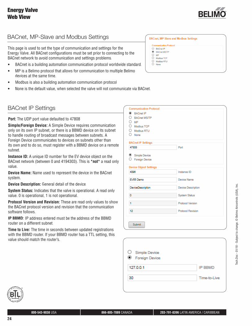
This page is used to set the type of communication and settings for theEnergy Valve. All BACnet confi gurations must be set prior to connecting to theBACnet network to avoid communication and settings problems.
• BACnet is a building automation communication protocol worldwide standard.
• MP is a Belimo protocol that allows for communication to multiple Belimodevices at the same time.
• Modbus is also a building automation communication protocol
• None is the default value, when selected the valve will not communicate via BACnet.
BACnet IP Settings
Port: The UDP port value defaulted to 47808
Simple/Foreign Device: A Simple Device requires communication only on its own IP subnet, or there is a BBMD device on its subnetto handle routing of broadcast messages between subnets. AForeign Device communicates to devices on subnets other thanits own and to do so, must register with a BBMD device on a remotesubnet.
Instance ID: A unique ID number for the EV device object on theBACnet network (between 0 and 4194303). This is *not* a read onlyvalue.
Device Name: Name used to represent the device in the BACnetsystem.
Device Description: General detail of the device.
System Status: Indicates that the valve is operational. A read onlyvalue. 0 is operational, 1 is not operational.
Protocol Version and Revision: These are read only values to showthe BACnet protocol version and revision that the communicationsoftware follows.
IP BBMD: IP address entered must be the address of the BBMDrouter on a different subnet.
Time to Live: The time in seconds between updated registrationswith the BBMD router. If your BBMD router has a TTL setting, thisvalue should match the router’s.
BACnet, MP-Slave and Modbus Settings
Tech
.Doc
- 01
/18
- Sub
ject
to c
hang
e. ©
Bel
imo
Airc
ontro
ls (U
SA),
Inc.

800-543-9038 USA 866-805-7089 CANADA 203-791-8396 LATIN AMERICA / CARIBBEAN
25
Energy ValveWeb View
BACnet MS/TP Settings
Baud Rate: The transmission speed within the MS/TPnetwork. All devices on the same network must be set tothe same baud rate. Available rates: 9600, 19200, 38400,76800, 115200.
MAC: The MAC address on the MS/TP network. This numbermust be unique within the network. Available values rangefrom 1 to 127.
Max Master: Max_Master must be large enough that allMS/TP MAC addresses are within it. If unsure, set to 127.
120 Ohm Termination: MS/TP networks require terminationresistors on end-of-line devices. Turning on this settingwill provide the required 120 Ohm termination on thisBACnet device. Use this setting with great caution as addingtermination resistance on a device in the middle of a networkcan cause signifi cant network problems.
Instance ID: A unique ID number for the EV device object onthe BACnet network (between 0 and 4194303). This is *not* aread only value.
Device Name: Name used to represent the device in theBACnet system.
System Status: Indicates that the valve is operational. A readonly value. 0 is operational, 1 is not operational.
Protocol Version and Revision: These are read only valuesto show the BACnet protocol version and revision that thecommunication software follows.
MS/TP Device Load: The MS/TP interface on the EnergyValve will create a 5/8 unit load on the network. This is a combination of local biasing resistors and a 1/8 load EIA-485 driver chip. Please keep this load fi gure in mind while determining network device limits and repeater requirements. Forreference, the EIA-485 specifi cation allows for a total of 32 device loads on a network without using repeaters. The transceiver isisolated, but the isolated reference is not exposed due to lack of pins 47K pull up resistors are connected from the isolated commonto – and isolated 5v to + and is fail safe.
Tech
.Doc
- 01
/18
- Sub
ject
to c
hang
e. ©
Bel
imo
Airc
ontro
ls (U
SA),
Inc.
800-543-9038 USA 866-805-7089 CANADA 203-791-8396 LATIN AMERICA / CARIBBEAN
26
Energy ValveWeb View
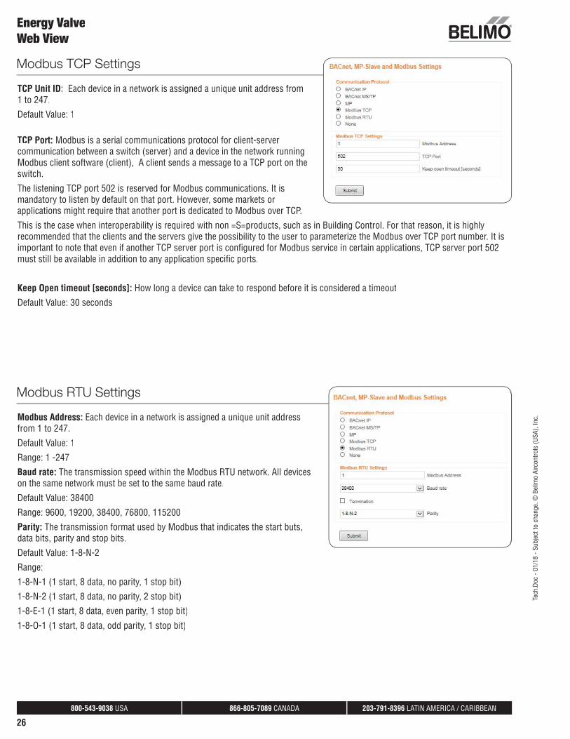
Modbus TCP Settings
TCP Unit ID: Each device in a network is assigned a unique unit address from1 to 247.
Default Value: 1
TCP Port: Modbus is a serial communications protocol for client-servercommunication between a switch (server) and a device in the network runningModbus client software (client), A client sends a message to a TCP port on theswitch.
The listening TCP port 502 is reserved for Modbus communications. It ismandatory to listen by default on that port. However, some markets orapplications might require that another port is dedicated to Modbus over TCP.
This is the case when interoperability is required with non =S=products, such as in Building Control. For that reason, it is highlyrecommended that the clients and the servers give the possibility to the user to parameterize the Modbus over TCP port number. It isimportant to note that even if another TCP server port is confi gured for Modbus service in certain applications, TCP server port 502must still be available in addition to any application specifi c ports.
Keep Open timeout [seconds]: How long a device can take to respond before it is considered a timeout
Default Value: 30 seconds
Modbus RTU Settings
Modbus Address: Each device in a network is assigned a unique unit addressfrom 1 to 247.
Default Value: 1
Range: 1 -247
Baud rate: The transmission speed within the Modbus RTU network. All deviceson the same network must be set to the same baud rate.
Default Value: 38400
Range: 9600, 19200, 38400, 76800, 115200
Parity: The transmission format used by Modbus that indicates the start buts,data bits, parity and stop bits.
Default Value: 1-8-N-2
Range:
1-8-N-1 (1 start, 8 data, no parity, 1 stop bit)
1-8-N-2 (1 start, 8 data, no parity, 2 stop bit)
1-8-E-1 (1 start, 8 data, even parity, 1 stop bit)
1-8-O-1 (1 start, 8 data, odd parity, 1 stop bit)
Tech
.Doc
- 01
/18
- Sub
ject
to c
hang
e. ©
Bel
imo
Airc
ontro
ls (U
SA),
Inc.

800-543-9038 USA 866-805-7089 CANADA 203-791-8396 LATIN AMERICA / CARIBBEAN
27
Datalog Service Connection Status: The status of the cloud connection.
Cloud Server: The address of the connected host Server.
MAC Address: The MAC address of the connected Energy Valve.
Datalog Service: Allows for data transfer between the Energy Valveand the cloud.
Task Service: Allows for automatic updating of the Energy Valve fl owand Delta T setpoints based on data captured by the valve in the cloud.
Update Mode: Allows for automatic updating of the Energy Valve fl owand Delta T setpoints based on data captured by the valve in the cloud.
Disabled: No updates are downloaded.
Device_Controlled: Updates are shown on the Maintenance page inWebview and not installed automatically, they are offered.
Cloud_Controlled_Manual: The updates need to be released by thedevice owner in the cloud. The device installs the update immediatelyafter release.
Cloud_Controlled Auto: The updates are released by Belimo andpropagated to the devices. The device installs the update immediatelyafter release.
Current owner: The individual that has current ownership of the device.This is typically the name of the user that confi gured the cloud settings and corresponds to the email address provided on initial setup.
Refresh Current owner: Simple refresh button to explicitly ask the cloud to tell us the current owner (for example after the productwas transferred in the cloud).
New owner: Used when starting a transfer from a current owner (or no owner yet) to a new owner which requires pressing theTransfer device button after new owner is entered.
Additional Information: By clicking on the load button displays more ownership information and device details.
Connection Status: Runs a routine that will help troubleshoot connection to the Belimo cloud.
Connection setup
Connectivity Requirements:Customer provided Ethernet CableDedicated Internet Connection
Requirements for cloud connectionGateway IP Address that allows a route to the internetIn case of DNS restrictions: IP addresses of internal DNS servers
Communication detailsUsed protocol is httpsPort of the server endpoint: 443DNS address of cloud server: https://connect.g2bcc.comp g
Firewall rule to allow communicationAction: Pass / AllowAddress family: IPv4Protocol: https over TCPSource: IP address of device or subnet designated to EnergyValve devicesDestination: https://connect.g2bcc.comp g
Energy ValveCloud Settings
Cloud Setting
Tech
.Doc
- 01
/18
- Sub
ject
to c
hang
e. ©
Bel
imo
Airc
ontro
ls (U
SA),
Inc.
800-543-9038 USA 866-805-7089 CANADA 203-791-8396 LATIN AMERICA / CARIBBEAN
28
Energy ValveCloud Settings
Daily Data Volume
Approximately 10MB
Communication between device and cloudAll communication between the device and the cloud is encrypted. The data is not readable without de-encryption.
Local confi gurationIn order to confi gure the device, the local webpage running on the integrated webserver has to be reached. The steps necessary depend on the local network setup and can vary. The easiest way to open the webpage is a direct LAN connection with a laptop running Windows and using the address http://belimo.local:8080 (the port number is 8080). Alternatives include, but are not limited to:using a wireless access point that connects to the device by LAN cable, then use any portable device with a web browser to open thewebpage from any internal network location if the LAN setup, especially routing and switching settings are appropriate using a directLAN connection with the correct network settings (IP address and subnet mask) and accessing the device with its initial fi xed IP (e.g.http://192.168.0.1:8080)
The website asks for login credentials. In order to confi gure the device for cloud access including network settings an admin user typeis necessary. The login credentials for the admin user are not publicly available, but communicated through customer support. Theuser is forced to change the admin password while completing the installation assistant.
There is an initial installation assistant as well as a manual method to confi gure the device to access the cloud. The following user datais requested when the user wants to enable cloud functionality:Mandatory data:Cloud E-Mail Account (valid E-Mail address, note: no need that this E-Mail address already is a valid Belimo cloud account)
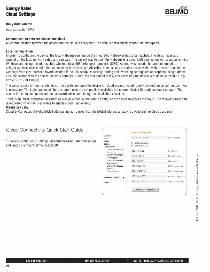
1. Locally Confi gure IP Settings on Actuator using LAN connectionand laptop via http://belimo.local:8080p
Cloud Connectivity Quick Start Guide
Tech
.Doc
- 01
/18
- Sub
ject
to c
hang
e. ©
Bel
imo
Airc
ontro
ls (U
SA),
Inc.

800-543-9038 USA 866-805-7089 CANADA 203-791-8396 LATIN AMERICA / CARIBBEAN
29
Energy ValveCloud Settings
2. Ownership Information and acknowledgement ofcloud services.
When the actuator is powered up initially theinstallation assistant is run and relevant cloud setupinformation like device owner and email address isentered as well as some valve set up information. To ensure this is complete the set up assistant can bestarted again by clicking the start wizard icon onthe submenu application under the settings menuheading.
3. Once actuator has been locally confi gured with appropriate IP address, email address, device owner and acknowledgement of cloudservices, connect live Ethernet cable and log back into the actuator via the IP network and verify connection to the Belimo cloud.
4. Go to cloud.belimo.com to create an account and allowdevice entrance into the cloud. The email address enteredwhen completing the set up wizard will be required whencreating the cloud account.
Tech
.Doc
- 01
/18
- Sub
ject
to c
hang
e. ©
Bel
imo
Airc
ontro
ls (U
SA),
Inc.

800-543-9038 USA 866-805-7089 CANADA 203-791-8396 LATIN AMERICA / CARIBBEAN
30
Energy ValveCloud Settings
5. Once connected the following services will be available:
Delta T Optimization and
Flow Setpoints
Cloud analytics provide
recommended Delta T and fl ow
setpoints which can be updated
remotely or automatically to save
time and improve effi ciency.
Performance Reporting
Key performance indicators are
graphically illustrated showing
current and historical performance
data of fl ow rates, energy usage,
Delta T, and other points of interest.
Lifetime Data Access
Secure, single consolidated
repository that stores and
provides system data access for
future optimization.
Online Tech Support
Belimo’s industry leading technical
support team available to assist
you remotely.
Software Updates
Latest software and security
updates automatically provided
for maximum productivity and
reliability.
Extended Warranty
5-year warranty is increased
to 7- year with Belimo cloud
connection.**
Cloud Interface
Overview Pageg
Status of Devices:Provides Total Energy Valves forassociated account. Only valves for theaccount will be displayed. Also indicatedhere is if there are problems with the devicein terms of operation that may need attentionand if there are valves coming in or leavingthe cloud via transfer.
Devices:
Displays the device name which is assigned in Webview by the user, Health status, Serial Number of the Energy Valve and the currentdevice owner. Clicking on the action folder displays the Valve data points, ability to download data, Valve details and transfer capability.
**The following provision supplements the applicable Terms and Conditions of Sale for the Energy Valve 3.0. The 5-year warranty foreseen in the Terms and Conditions of Sale shall be replaced by a 7-year warranty, provided the following conditions are fulfi lled:
• The Cloud-connection on the respective BELIMO device is activated• The respective BELIMO device has been allocated to a Cloud-Account • At the time of the warranty claim the connection ratio between the BELIMO device and the BELIMO-Cloud is at least 90% (the connection ratio is
determined by the amount of hours of Cloud-connection of the BELIMO device divided by its operating hours).
Tech
.Doc
- 01
/18
- Sub
ject
to c
hang
e. ©
Bel
imo
Airc
ontro
ls (U
SA),
Inc.

800-543-9038 USA 866-805-7089 CANADA 203-791-8396 LATIN AMERICA / CARIBBEAN
31
Device Management Pageg g
Provides a single page focused on managing theEnergy Valve in the cloud. Displays the devicename which is assigned in Webview by the user,Health status, Serial Number of the Energy Valveand the current device owner. There is also searchfunctionality that allows for search by serialnumber or Energy Valve name.
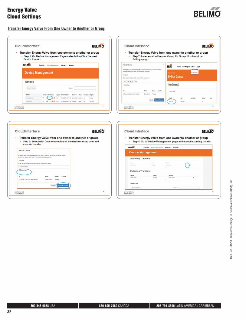
Under the Action heading are 3 specific functions:
1. Transfer Energy Valve from one owner toanother by clicking on the orange arrow. To have data available for the new owner, theoption of with data should be selected. Thisappears once the transfer icon is clicked.
2. Display Valve data points, ability to download data, Valve details and transfer capability by clicking the action folder.
3. Delete the selected Energy valve from the cloud by clicking the trash can icon.
Settings Pageg g
Provides page focused on the information for two main areasAccount Settingsg which includes information about the user/owner including Name, Geographic information, Email address,and current password as well as ability to change currentpassword. Also My User Groupsy p which displays the current usergroups and ability to create a new group and add members to it.
Energy ValveCloud Settings
Tech
.Doc
- 01
/18
- Sub
ject
to c
hang
e. ©
Bel
imo
Airc
ontro
ls (U
SA),
Inc.
800-543-9038 USA 866-805-7089 CANADA 203-791-8396 LATIN AMERICA / CARIBBEAN
32
Energy ValveCloud Settings
Transfer Energy Valve From One Owner to Another or Groupgy p
Tech
.Doc
- 01
/18
- Sub
ject
to c
hang
e. ©
Bel
imo
Airc
ontro
ls (U
SA),
Inc.

800-543-9038 USA 866-805-7089 CANADA 203-791-8396 LATIN AMERICA / CARIBBEAN
33
Support Pagepp g
Provides relevant support information,Contact for Belimo Headquarters,Support Request, API DeveloperDocumentation and Delta T OptimizeRequest. For the Delta T Optimizerequest it requires at least 2 monthsof data for proper analysis.
Energy ValveCloud Settings
Field Programming andCommissioning Options
All Energy Valve actuators can be fi eldprogrammed with either the ZTH UShandheld tool or with an Ethernet cableconnected to a computer with webbrowser to access the actuator’s webpage (Web View). Refer to the tablebelow for a list of settings than can bechanged in the fi eld.
1
2
3
4
5
6
7
8
9
Tech
.Doc
- 01
/18
- Sub
ject
to c
hang
e. ©
Bel
imo
Airc
ontro
ls (U
SA),
Inc.
800-543-9038 USA 866-805-7089 CANADA 203-791-8396 LATIN AMERICA / CARIBBEAN
34
Energy ValveCloud Settings
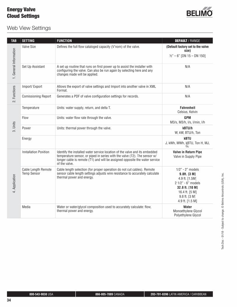
TAB SETTING FUNCTION DEFAULT / RANGE
1. G
ener
al In
form
atio
n Valve Size Defi nes the full fl ow cataloged capacity (V’nom) of the valve. (Default factory set to the valve size)
½” – 6” [DN 15 – DN 150]
Set Up Assistant A set up routine that runs on fi rst power up to assist the installer with confi guring the valve. Can also be run again by selecting here and any changes made will be applied.
N/A
2. F
unct
ions Import/ Export Allows the export of valve settings and Import into another valve in XML
Format.N/A
Comissioning Report Generates a PDF of valve confi guration settings for records. N/A
3. U
nits
Temperature Units: water supply, return, and delta T. FahrenheitCelsius, Kelvin
Flow Units: water fl ow rate through the valve. GPMM3/s, M3/h, l/s, l/min, l/h
Power Units: thermal power through the valve. kBTU/hW, kW, BTU/h, Ton
Energy kBTUJ, kWh, MWh, kBTU, Ton H, MJ,
GJ
4. A
pplic
atio
n
Installation Position Identify the installed water service location of the valve and its embedded temperature sensor, or piped in series with the valve (T2). The sensor w/ longer cable is remote (T1) and will be assigned opposite the water serviceof the valve.
Valve in Return PipeValve in Supply Pipe
Cable Length Remote Temp Sensor
Cable length selection (for proper operation do not cut cables). Remote sensor cable length settings adjusts wire resistance to accurately calculate thermal power and energy.
1/2” - 2” models9.8ft. [3 M]
4.9 ft. [1.5M]2 1/2” - 6” models
32.8 ft. [10 M]16.4 ft. [5 M]9.8 ft. [3 M]
4.9 ft. [1.5 M]
Media Water or water/glycol composition used to accurately calculate: fl ow, thermal power and energy.
Water Monoethylene GlycolPolyethylene Glycol
Web View Settings
Tech
.Doc
- 01
/18
- Sub
ject
to c
hang
e. ©
Bel
imo
Airc
ontro
ls (U
SA),
Inc.

800-543-9038 USA 866-805-7089 CANADA 203-791-8396 LATIN AMERICA / CARIBBEAN
35
TAB SETTING FUNCTION DEFAULT / RANGE
5. A
nalo
g Fe
edba
ck
Feedback Actuator analog feedback signal output on wire #5 u-signal. Flow Power, T supplyT return, delta TValve position
Range Actuator analog feedback linear signal range. 2-10 V0.5-10 V0-10 V
Maximum Setting to equate 10 VDC or maximum feedback information. Setting must match the DDC range maximum setting. The grey box is an entry fi eld and not the actual measured feedback and will hold the last value entered in it. The factory setting on this is 0.
Flow0 to V’Nom
Position0 to 100%(0-90 deg.)Temperaturep
32°F to 212°F0°C to 100°C
Power0 to P’nom
6. O
verr
ide
Override functions Override functions to move the valve to a particluar point or position which can be used for testing and commissoning purposes. All engaged overrides stop and go back to normal operation automatically after two hours.
Auto Normal operation no override. Auto
Close Moves actuator to close valve. N/A
Open Moves actuator to open valve. N/A
V’nom In fl ow control moves the actuator to full open position. N/A
V’max In fow control moves the actuator to V’max setting. N/A
Motor Stop Stops the valve at current position. N/A
P’Nom In power control mode moves the actautor to P’nom position (full open). N/A
P’max In Power control mode moves the actautor to P’max setting. N/A
Simulated operation Engages simulation of fl ow and temperature that can be viewed on the overview page.
N/A
7. C
ontro
l Set
tings
Setpoint Source Defi nes how the BMS valve set point is sent to the acuator either analog on wire 3 or via BACnet, Modbus or MP).
Analog Bus (BACnet, Modbus, MP)
Control Mode Controlled variable assigned to the actuator analog input y-signal, wire # 3. Flow ControlPower Control
Position Control
Invert Signal “No” valve modulates open when 10 VDC is received. “Yes” 10 VDC signal closes the valve.
No Yes
Signal Characteristic Setting when Controls modes are set to Flow or Position• Equal Percentage fl ow yields coil thermal power roughly Equal to the
control signal.• “linear” 50% controller command yields 50% fl ow output or position.
Equal Percentage Linear
8. M
axim
um
and
Lim
itatio
n Vmax Used with Flow Control mode, this is the maximum fl ow setting of the valve with a full fl ow output from the controller.
V’Nom
Vmin Used with Flow Control mode, this is the minimum fl ow setting of the valve to maintain a minumum fl ow rate for particualar applications.
30% - 100% of V’nomDefi ned by size in Webview
Web View Settings Continued
Energy ValveCloud Settings
Tech
.Doc
- 01
/18
- Sub
ject
to c
hang
e. ©
Bel
imo
Airc
ontro
ls (U
SA),
Inc.

800-543-9038 USA 866-805-7089 CANADA 203-791-8396 LATIN AMERICA / CARIBBEAN
36
TAB SETTING FUNCTION DEFAULT / RANGE
9. D
elta
T M
anag
er
Delta T Limiting Function
Setting to disabled or enabled with limiting logic: dT Manger or dT Manager Scaling. Both use settings“Delta T Limiting Value” but only dT Manager Scaling uses the “Flow Saturation Value.
Disabled = “-“ dT Manager
dT Manager Scaling
Delta T Limiting Value Low limit parameter for dT setpoint: • For dT Manger this is the dT setpoint. • For dT Manager Scaling this will reset so the dT setpoint is scaled, or
variable. The Data Analysis Tool may be used to help determine this value.The grey box is an entry fi eld and not the actual measured Delta T and will hold the last value that is entered in it.
10°F2°F to100°F
1.1°C to 55.5°CDefault >30% of V’maxOption >10% of V’nom
Flow Saturation Value Parameter used with dT Manager Scaling to reset the Delta T Limiting Value. When dT Manager Scaling is active:• If actual fl ow is less than this parameter the dT setpoint will be reset
below the Delta T Limiting Value.• If actual fl ow is equal to this parameter the dT setpoint will be equal to
Delta T Limiting Value. • If actual fl ow is greater than this parameter the dT setpoint will be reset
above the Delta T Limiting Value.The Data Analysis Tool may be used to help determine this value.
(User defi ned)
>30%-100% of V’max
Web View Settings Continued
Energy ValveCloud Settings
Tech
.Doc
- 01
/18
- Sub
ject
to c
hang
e. ©
Bel
imo
Airc
ontro
ls (U
SA),
Inc.

800-543-9038 USA 866-805-7089 CANADA 203-791-8396 LATIN AMERICA / CARIBBEAN
37
Operating InstructionsZTH US
The ZTH US is a tool created to easily adapt the
fl ow settings of the Energy Valve in the fi eld. It
directly connects to the Belimo actuator.
Technical Information
Supply 24 VAC/DC
Communication PP
Used with actuator types LR, NR, AR, GR, AKR, GKR, EV, AVK
RE-PROGRAMMING PROCESS:
Initial ScreenWhen connected the display will show “Startup Progress” thisprocess will take approximately 30 seconds.
Screen 1Start Energy Valve process by pressing the down arrow.The first screen displays setpoint relative in % (SpRel). Press the down arrow to advance.
CONNECTION PROCESS:
NR, AR, GR, AKR, GKR, EV, AVK SeriesLR, Nthe interface on the top of the actuator. Use trter turn to lock in place. Connect the Quar
other end of the cable into the ZTH US. Theotheractuator must be powered for the ZTH US to function.(Leave all of the wires of the actuator installed.)
Startup Progress SpRel50%Te
ch.D
oc -
01/1
8 - S
ubje
ct to
cha
nge.
© B
elim
o Ai
rcon
trols
(USA
), In
c.

800-543-9038 USA 866-805-7089 CANADA 203-791-8396 LATIN AMERICA / CARIBBEAN
38
Operating InstructionsZTH US
ZTH US SETTINGS
Setting Description Range and UOM CapabilityAnalog Input signal as a % of full signal 0 – 100% Read Only
RelPos Valve position as a % of full opening 0 – 100% Read Only
RelFlow Current flow as % of V’max 0 – 100% Read Only
AbsFlow Flow in GPM GPM Read Only
T1 remote Temperature opposite valve side F Read Only
T2 embedded Temperature at valve F Read Only
DeltaT Supply and return temperature differential F Read Only
RelPower Current power as % of P’max % Read Only
Abs power Current power output KBTU/hr Read Only
Cooling Energy Total cooling power since last reset KBTU Read Only
Heating Energy Total heating power since last reset KBTU Read Only
Override 1=Auto, 2=Close, 3=Open, 4=V’nom, 5=V’max,
1-9 Write Only
SpPos Override 0 – 100% Write Only
Mode (0 = 0.5 – 10 V, 1= 2 – 10 V) 0 - 1 Write Only
ModeY Inv (0 = not inverted, 1= inverted) 0 - 1 Write Only
V’max Can be a percentage or flow. 30 – 100%0 – 1000GPM
Write Only
P’max Can be a percentage or power 1 – 100%1 – 15000KBTU/hr
Write Only
Control Mode 0=Position Control, 1=Flow Control, 2=Power Control
0 - 2 Write Only
Install Pos 0= Return Flow, 1= Supply Flow
0 - 1 Write Only
IP-Address Valve IP on LAN Read Only
DeltaT Limit 0 = Disabled, 1 = dT-Manager,2 = dT-Manager Scaling
0 - 2 Write Only
SpDeltaT Delta T Limiting Valve 2 – 100 F Write Only
SpFlowDeltaT Flow Saturation Value 0 – 1000 GPM Write Only
SensorStatus 0 = OK, 1 = Not OK, 2 = OK Air bubbles
0 - 2 Read Only
Glycol Concentration % Glycol concentration % reported by the Energy Valve only shown if activated
0-100% Read Only
Move through the displays. The chart below shows the complete list.
6=MotorStop, 7=P’nom, 8=P’max, 9=Set Point Position Override
Tech
.Doc
- 01
/18
- Sub
ject
to c
hang
e. ©
Bel
imo
Airc
ontro
ls (U
SA),
Inc.

800-543-9038 USA 866-805-7089 CANADA 203-791-8396 LATIN AMERICA / CARIBBEAN
39
Actuator Adaptation
The actuator adaptation button calibrates the input signal range (2-10V)to the actuator angle of rotation range by driving the actuator to themechanical end stops. Completion of the cycle, the actuator will followthe current input signal. By default, the actuator will run the adaptationcycle after the fi rst power up. Belimo recommends performing a manualadaptation to the actuator if the actuator has been replaced. The manualadaptation can be activated by pressing the translucent “Adaptation” LEDbutton for three seconds.
Belimo Data Analysis Tool
Data Analysis Tool is used to analyze imported data from the “Web View Data Logging”. The Data Analysis Tool can bedownloaded from the Energy Valve web page (www. energyvalve.com).
• View power and delta T curves for different fl ows for a coil.
• View and diagnose system behavior based on delta T, fl ow, and power data collected for 13 months.
• Help in the continuous commissioning of the Energy Valve. It does this by suggesting optimized delta T and fl ow saturationset points to be confi gured in the Energy Valve.
Compatibility:
The Data Analysis Tool runs with Microsoft Excel. There are two versions of the data analysis tool available. Please select thecorrect version to match the version of Excel you are running.
• Data analysis tool 2003 version; to be used with Microsoft Excel 2003 only.
• Data analysis tool 2007_2010 version; to be used with Microsoft Excel 2007 and 2010.
Constant Commissioning of the Energy Valve:
This tool can be used to constantly commission the Energy Valve.
Note: Keep a record of settings changes with date and time. This data can serve as a coil performance or maintenance record.
To use the Data Analysis Tool, the Energy Valve needs to collect data for a period that will represent full or close to full coilsaturation. Use the following steps to import the data into the tool:
A. Download the coil data (CSV fi les) from the Energy Valve’s Web View to your computer.
B. Import the .csv fi les in to the Data Analysis Tool. Multiple fi les can be imported at once.
C. Select the Delta T Determination tab. Then, click the Calculate button to determine the optimized Delta T and Flow Saturationset points if the coil data shows close to saturation.
D. Log onto the Energy Valve Web View. Enter the delta T Setpoint (Delta T Limit Value) and Flow Saturation (Flow SaturationLimit Value) set points in the Web View Setting page.
Belimo recommends performing this commissioning at least once annually to maximize system energy effi ciency.
Energy ValveTe
ch.D
oc -
01/1
8 - S
ubje
ct to
cha
nge.
© B
elim
o Ai
rcon
trols
(USA
), In
c.

800-543-9038 USA 866-805-7089 CANADA 203-791-8396 LATIN AMERICA / CARIBBEAN
40
Downloading Coil Data from Web View
• Select time frame for exporting data
• Short Term data is captured every 30 seconds.
• Long Term data is captured for a period of 15 minutesand up to 2 hours.
• Data can be directly imported into data analysis tool. Files exportin .csv format.
Energy ValveData Analysis Tool
Delta T Determination
A. Click to import Data Logging fi les generated by the Energy Valve Web View.
B. Click to calculate the optimum delta T and fl ow saturation for the coil.
C. Delta T Setpoint and Flow Saturation are calculated based on the provided data. These values are then enteredinto the Energy Valve Web View Settings area. The new settings will provide optimized delta T performance.
D. Flow saturation point.
Tech
.Doc
- 01
/18
- Sub
ject
to c
hang
e. ©
Bel
imo
Airc
ontro
ls (U
SA),
Inc.

800-543-9038 USA 866-805-7089 CANADA 203-791-8396 LATIN AMERICA / CARIBBEAN
41
Tech
.Doc
- 01
/18
- Sub
ject
to c
hang
e. ©
Bel
imo
Airc
ontro
ls (U
SA),
Inc.
Problem Field Observations Possible Solution
Actuator will not move. Actuator green LED is not on or fl ashing. Verify the power supply and control signal arewired and operating correctly. If the actuator wiring is correct and the Green LED is not blinking the actuator has failed. Note: the LED is solid green while booting up.
Actuator green LED is fl ashing but the valve will not move.
Valve may have debris.
Depress the black gear release button on the side of the actuator and use the override handle to clear any debris that may have clogged the valve. If the valve does not move, then remove the actuator from valve and try to manually operate the valve stem.
Actuator does not modulate with the control signal as expected.
Valve throttles to either full open or closed. Verify the hydronic circuit is fi lled, water isfl owing, and isolation valves are opened. WhenMode of Control is set to Flow or Power, any control signal greater than 0.5 or 2 VDC means there is a fl ow command. The fl ow or power logic will open the valve to satisfy the demand. Delta T Manager may be active.
Valve is yielding low fl ow but cannot be commanded to the full fl ow setting.
Valve is partially open but will not move to a fullopen position with a full signal command.
If the Delta T Manager is enabled it may be regulating the T. Disable Delta T Manager untilthe chiller or boiler is operating correctly.
Flow is lower than expected. Example: 50% fl ow signal is yielding 20% fl ow. If equal percentage is the setting for the Control Signal Characteristic this is normal. For a correlation between fl ow and input signal, see the Equal Percentage Flow table on page 41.
Requested fl ow cannot be reached; actual fl ow is lower than commanded fl ow.
Valve is full open. If the valve is fully open and fl ow feedback is 5% lower than fl ow set point this event is captured in the Status Summary in Web View. Increase the pump differential pressure to resolve low fl ow problems.
Flow measurements are not stable. Air may be in the system. Check for air in the system. Remove air from the system to solve the problem.
Flow Control, Power Control, and dT Manager Scaling are not working.
Flow calculation is 0 GPM. See any fl ow error listed on the Status area of the Web View or use the ZTH US.
Temperature sensor does not work. Web View Indication:-15°F > Temp. > 300°F-26°C > Temp. > 149°C
Remove remote sensor wires from the terminals and verify resistance with an ohm meter, replace if damaged. Below are typical PT 1000 readings:
176°F [80°C] = 1347 ohms68°F [20°C] = 1078 ohms50°F [10°C] = 1039 ohms
ZTH: Sensor status not OK Web View status page: Flow Sensor Error Counter > 0
Check flow sensor to see if it is reading flow when valve is open. If it is not, contact Technical Support.
Device running slow when viewed in BACnet front end.
Device busy or slow. Reduce the number of points being pulled in BACnet system and or reduce the polling rate.
Valve does not respond to analog control signal. 2-10 analog signal is modulated but the actuator does not respond.
Once Object SpRel has been written to via BACnet the valve will no longer respond to analog signal. The only way to restore the valve responding to the analog control signal is to power cycle the actuator.
Flow Sensor does not work properly. For 2½” through 6” - Flow sensor reading is below 3mA or higher than 20.5mA.
For ½”through 2” - Error byte communicates failure status.
Replace sensor.
Energy ValveTroubleshooting
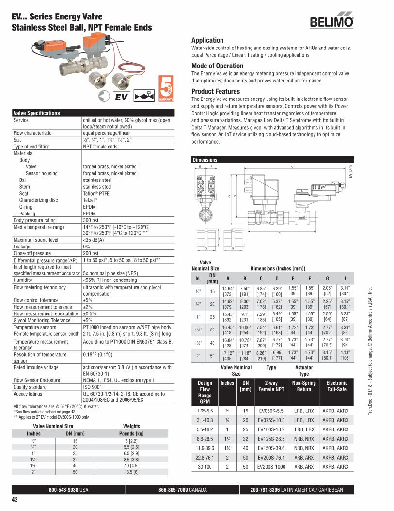
800-543-9038 USA 866-805-7089 CANADA 203-791-8396 LATIN AMERICA / CARIBBEAN
42
ApplicationWater-side control of heating and cooling systems for AHUs and water coils. Equal Percentage / Linear: heating / cooling applications.
Mode of OperationThe Energy Valve is an energy metering pressure independent control valve that optimizes, documents and proves water coil performance.
Product FeaturesThe Energy Valve measures energy using its built-in electronic fl ow sensorand supply and return temperature sensors. Controls power with its Power Control logic providing linear heat transfer regardless of temperature and pressure variations. Manages Low Delta T Syndrome with its built inDelta T Manager. Measures glycol with advanced algorithms in its built in fl ow sensor. An IoT device utilizing cloud-based technology to optimize performance.
Dimensions
G
I
E F
B
A
C D
G
I
EV_D
im
ValveNominal Size Dimensions (Inches [mm])
In. DN [mm] A B C D E F G I
½” 15 14.64"[372]
7.50"[191]
6.85"[174]
6.29"[160]
1.55"[39]
1.55"[39]
2.05”[52]
3.15”[80.1]
¾” 20 14.92" [379]
8.00" [203]
7.02"[178]
6.37"[162]
1.55”[39]
1.55”[39]
2.25”[57]
3.15”[80.1]
1” 25 15.43"[392]
9.1"[231]
7.29"[185]
6.49"[165]
1.55”[39]
1.55”[39]
2.50”[64]
3.23”[82]
1¼” 32 16.45"[418]
10.00"[254]
7.54"[192]
6.61"[168]
1.73"[44]
1.73"[44]
2.77”[70.5]
3.39”[86]
1½” 40 16.84"[428]
10.78"[274]
7.87"[200]
6.77"[172]
1.73”[44]
1.73”[44]
2.77”[70.5]
3.70”[94]
2” 50 17.12”[435]
11.18”[284]
8.26”[210]
6.96[177]
1.73”[44]
1.73”[44]
3.15”[80.1]
4.13”[105]
EV... Series Energy ValveStainless Steel Ball, NPT Female Ends
Valve Nominal Size
Type Actuator Type
Design Flow
Range GPM
Inches DN [mm]
2-way Female NPT
Non-Spring Return
ElectronicFail-Safe
1.65-5.5 ½ 15 EV050S-5.5 LRB, LRX AKRB, AKRX
3.1-10.3 ¾ 20 EV075S-10.3 LRB, LRX AKRB, AKRX
5.5-18.2 1 25 EV100S-18.2 LRB, LRX AKRB, AKRX
8.6-28.5 1¼ 32 EV125S-28.5 NRB, NRX AKRB, AKRX
11.9-39.6 1½ 40 EV150S-39.6 NRB, NRX AKRB, AKRX
22.8-76.1 2 50 EV200S-76.1 ARB, ARX AKRB, AKRX
30-100 2 50 EV200S-1000 ARB, ARX AKRB, AKRX
Valve Specifi cationsService chilled or hot water, 60% glycol max (open
loop/steam not allowed)Flow characteristic equal percentage/linearSize ½”, ¾”, 1”, 1¼”, 1½”, 2”Type of end fi tting NPT female endsMaterials
Body Valve forged brass, nickel plated Sensor housing forged brass, nickel platedBall stainless steelStem stainless steelSeat Tefl on® PTFECharacterizing disc Tefzel®
O-ring EPDMPacking EPDM
Body pressure rating 360 psiMedia temperature range 14°F to 250°F [-10°C to +120°C]
39°F to 250°F [4°C to 120°C]**Maximum sound level <35 dB(A)Leakage 0%Close-off pressure 200 psiDifferential pressure range(ΔP) 1 to 50 psi*, 5 to 50 psi, 8 to 50 psi**Inlet length required to meet specifi ed measurement accuracy 5x nominal pipe size (NPS)Humidity <95% RH non-condensingFlow metering technology ultrasonic with temperature and glycol
compensationFlow control tolerance ±5%Flow measurement tolerance ±2%Flow measurement repeatability ±0.5%Glycol Monitoring Tolerance ±5%Temperature sensors PT1000 insertion sensors w/NPT pipe bodyRemote temperature sensor length 2 ft. 7.5 in. [0.8 m] short, 9.8 ft. [3 m] longTemperature measurement tolerance
According to PT1000 DIN EN60751 Class B.
Resolution of temperature sensor
0.18°F (0.1°C)
Rated impulse voltage actuator/sensor: 0.8 kV (in accordance with EN 60730-1)
Flow Sensor Enclosure NEMA 1, IP54, UL enclosure type 1Quality standard ISO 9001Agency listings UL 60730-1/2-14, 2-18, CE according to
2004/108/EC and 2006/95/ECAll fl ow tolerances are @ 68°F (20°C) & water.*See fl ow reduction chart on page 43.** Applies to 2” EV model EV200S-1000 only.
EV
Valve Nominal Size WeightsInches DN [mm] Pounds [kg]
½” 15 5 [2.2]¾” 20 5.5 [2.5]1” 25 6.5 [2.9]
1¼” 32 8.5 [3.8]1½” 40 10 [4.5]2” 50 13.5 [6]
Tech
.Doc
- 01
/18
- Sub
ject
to c
hang
e. ©
Bel
imo
Airc
ontro
ls (U
SA),
Inc.

800-543-9038 USA 866-805-7089 CANADA 203-791-8396 LATIN AMERICA / CARIBBEAN
43
Tech
.Doc
- 01
/18
- Sub
ject
to c
hang
e. ©
Bel
imo
Airc
ontro
ls (U
SA),
Inc.
Valve Specifi cationsService chilled or hot water, 60% glycol max (open
loop/steam not allowed)Flow characteristic equal percentage/linearSize 2½”, 3”, 4”, 5”, 6”Type of end fi tting pattern to mate with ANSI 125 fl angeMaterials
Body Valve cast iron - GG25 Sensor housing ductile iron - GGG50Ball stainless steelSeat PTFECharacterizing disc stainless steelPacking 2 EPDM O-rings, lubricated
Body pressure rating according to ANSI 125, standard class BMedia temperature range 14°F to 250°F [-10°C to +120°C]Maximum sound level 70 dBAConductivity of media min. 20uS/cmLeakage 0%Close-off pressure 100 psiDifferential pressure range(ΔP) 1 to 50 psi*, 5 to 50 psiInlet length required to meet specifi ed measurement accuracy 5x nominal pipe size (NPS)Humidity <95% RH non-condensingFlow metering technology electromagneticFlow control tolerance ±5%Flow measurement tolerance ±2%Flow measurement repeatability ±0.5%Temperature sensors 32.8 ft. [10m]
PT1000 insertion senorsThermal well ½ NPT
Remote temperature sensor lengthStandard 32.8 ft. [10 m]Optional 4.9 ft. [1.5m], 9.8 ft. [3m], 16.4 ft. [5m]
Temperature measurement tolerance
According to PT1000 DIN EN60751 Class B.
Resolution of temperature sensor
0.18°F (0.1°C)
Rated impulse voltage actuator/sensor: 0.8 kV (in accordance with EN 60730-1)
Flow sensor enclosure NEMA 1, IP54, UL enclosure type 1Quality standard ISO 9001Agency listings UL 60730-1/2-14, 2-18, CE according to
2004/108/EC and 2006/95/EC
ApplicationWater-side control of heating and cooling systems for AHUs and water coils. Equal Percentage / Linear: heating / cooling applications.
Mode of OperationThe Energy Valve is an energy metering pressure independent control valve that optimizes, documents and proves water coil performance.
Product FeaturesThe Energy Valve measures energy using its built-in electronic fl ow sensorand supply and return temperature sensors. Controls power with its Power Control logic providing linear heat transfer regardless of temperature and pressure variations. Manages Low Delta T Syndrome with its built in Delta T Manager. An IoT device utilizing cloud-based technology to optimize performance.
Dimensions
B
D
G
I
C
E F
H2H1
A
D134
1
ValveNominal Size Dimensions (Inches [mm])
In. DN [mm] A B C D E F G I
2½” 65 17.9”[454]
17.9”[454]
11.2”[284]
7.9”[201]
3.64”[92]
3.64”[92]
5.50”[140]
0.75”[19]
3” 80 19.7” [499]
19.7” [499]
11.8”[300]
7.9”[201]
3.94”[100]
3.94”[100]
6.07”[154]
0.75”[19]
4” 100 22.85”[581]
22.85”[581]
12.8”[325]
8.3”[211]
3.75”[95]
3.75”[95]
7.50”[190.5]
0.75”[19]
5” 125 25.18”[640]
25.18”[640]
14.4”[366]
9.4”[239]
5”[127]
5”[127]
8.50”[215.9]
0.88”[22]
6” 150 30.2”[767]
30.2”[767]
15.4”[391]
10.4”[264]
5.5”[140]
5.5”[140]
9.50”[241.3]
0.88”[22]
Valve Nominal Size WeightsInches DN [mm] Pounds [kg]
2½” 65 52 [23.6]3” 80 63 [28.7]4” 100 89 [40.5]5” 125 120 [54.7]6” 150 154 [70.0]
EV... Series Energy ValveStainless Steel Ball, ANSI 125 Flange
All fl ow tolerances are @ 68°F (20°C) & water.* See fl ow reduction table on page 43.
Available Flow Rates
Valve Nominal Size
Type Actuator Type
Design Flow
Range GPM
Inches DN [mm]
2-way Flanged
Non-Spring Return
ElectronicFail-Safe
38-127 2½ 65 EV250S-127 ARB, ARX AKRB, AKRX
54-180 3 80 EV300S-180 ARB, ARX AKRB, AKRX
95-317 4 100 EV400S-317 GRB, GRX AKRB, AKRX
149-495 5 125 EV500S-495 GRB, GRX GKRB, GKRX
214-713 6 150 EV600S-713 GRB, GRX GKRB, GKRX
EV
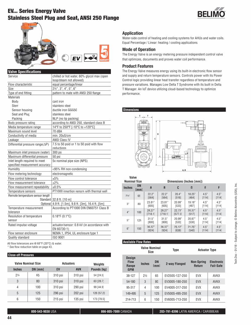
800-543-9038 USA 866-805-7089 CANADA 203-791-8396 LATIN AMERICA / CARIBBEAN
44
Valve Specifi cationsService chilled or hot water, 60% glycol max (open
loop/steam not allowed)Flow characteristic equal percentage/linearSize 2½”, 3”, 4”, 5”, 6”Type of end fi tting pattern to mate with ANSI 250 fl angeMaterials
Body cast ironStem stainless steelSensor housing ductile iron GGG50Seat and Plug stainless steelPacking NLP (no lip packing)
Body pressure rating according to ANSI 250, standard class BMedia temperature range 14°F to 250°F [-10°C to +120°C]Maximum sound level 70 dBAConductivity of media min. 20uS/cmLeakage ANSI Class IVDifferential pressure range(ΔP) 7.5 to 50 psid or 1 to 50 psid with fl ow
reductionsMaximum inlet pressure (water) 300 psiMaximum differential pressure 50 psiInlet length required to meet specifi ed measurement accuracy
5x nominal pipe size (NPS)
Humidity <95% RH non-condensingFlow metering technology electromagneticFlow control tolerance ±5%Flow measurement tolerance ±2%Flow measurement repeatability ±0.5%Temperature sensors PT1000 insertion senors with thermal well Remote temperature sensor length
Standard 32.8 ft. [10 m]Optional 4.9 ft. [1.5m], 9.8 ft. [3m], 16.4 ft. [5m]
Temperature measurement tolerance
According to PT1000 DIN EN60751 Class B
Resolution of temperature sensor
0.18°F (0.1°C)
Rated impulse voltage actuator/sensor: 0.8 kV (in accordance with EN 60730-1)
Flow sensor enclosure NEMA 1, IP54, UL enclosure type 1Quality standard ISO 9001
ApplicationWater-side control of heating and cooling systems for AHUs and water coils. Equal Percentage / Linear: heating / cooling applications.
Mode of OperationThe Energy Valve is an energy metering pressure independent control valve that optimizes, documents and proves water coil performance.
Product FeaturesThe Energy Valve measures energy using its built-in electronic fl ow sensorand supply and return temperature sensors. Controls power with its Power Control logic providing linear heat transfer regardless of temperature and pressure variations. Manages Low Delta T Syndrome with its built in Delta T Manager. An IoT device utilizing cloud-based technology to optimize performance.
Dimensions
A, B
D
C
E F
EV... Series Energy ValveStainless Steel Plug and Seat, ANSI 250 Flange
All fl ow tolerances are @ 68°F (20°C) & water.* See fl ow reduction table on page 43.
Available Flow Rates
Valve Nominal Size Type Actuator Type
Design Flow
Range GPM
Inches DN [mm] 2-way Flanged Non-Spring
ReturnElectronicFail-Safe
38-127 2½ 65 EV250S-127-250 EVX AVKX
54-180 3 80 EV300S-180-250 EVX AVKX
95-317 4 100 EV400S-317-250 EVX AVKX
149-495 5 125 EV500S-495-250 EVX AVKX
214-713 6 150 EV600S-713-250 EVX AVKX
EV
ValveNominal Size Dimensions (Inches [mm])
Inches DN [mm] A B C D E F
2½” 65 22.2”[564]
22.2”[564]
20.4”[516]
18.25”[464]
4.5”[114]
4.5”[114]
3” 80 23.81”[605]
23.81”[605]
20.99”[533]
19.18”[487]
4.5”[114]
4.5”[114]
4” 100 28.27”[718.1]
28.27”[718.1]
22.73”[577.3]
20.37”[517]
4.5”[114]
4.5”[114]
5” 125 31.5”[800]
31.5”[800]
20.99”[533]
20.87”[530]
4.5”[114]
4.5”[114]
6” 150 36.37”[924]
36.37”[924]
25.12”[638]
21.25”[540]
4.5”[114]
4.5”[114]
Close-off Pressures
Valve Nominal Size Actuators WeightsInches DN [mm] EV AVK Pounds [kg]
2½ 65 310 psi 310 psi 54 [24.5]
3 80 310 psi 310 psi 63 [28.7]
4 100 310 psi 290 psi 99 [44.9]
5 125 296 psi 202 psi 126 [57.2]
6 150 215 psi 135 psi 173 [78.5]
Tech
.Doc
- 01
/18
- Sub
ject
to c
hang
e. ©
Bel
imo
Airc
ontro
ls (U
SA),
Inc.

800-543-9038 USA 866-805-7089 CANADA 203-791-8396 LATIN AMERICA / CARIBBEAN
45
Tech
.Doc
- 01
/18
- Sub
ject
to c
hang
e. ©
Bel
imo
Airc
ontro
ls (U
SA),
Inc.
System Ground
Non-Spring Return LR, NR, GR, AR and Electronic Fail-Safe Actuators AKR and GKR
Actuator SpecificationsPower supply 24 VAC ± 20%
24 VDC ± 10%Electric frequency 50/60 HzPower consumption LR Series 4W NR Series 5W GR Series 8W AR Series 5W (½” to 2”), 7W (2½” to 6”) AKR Series 14W (½” to 2”), 16W (2½” to 6”) GKR Series 17WTransformer sizing LR Series 7 VA (class 2 power source) NR Series 8 VA (class 2 power source) GR Series 12 VA (class 2 power source) AR Series 8 VA (½” to 6”), 11 VA (2½” to 6”) (class 2
power source) AKR Series 23 VA (½” to 2”), 26VA (2½” to 6”) (class 2
power source) GKR Series 29 VA (class 2 power source)Electrical connection 18 GA, plenum rated cable
½” conduit connectorprotected NEMA 2 (IP54) 3 ft. [1 m] cable
Overload protection electronic throughout 0° to 90° rotationOperation range Y 2 to 10 VDC (default) VDC variableControl modulatingInput impedance 100 kΩ (0.1 mA), 500ΩFlow Feedback 2 to 10 VDC (default), VDC variableCommunication BACnet IP, BACnet MS/TP, Listed by BTL, web
server, Belimo MP-BusDirection of rotation motor electronically variable
fail-safe reversible with built-in switchManual override external push buttonRunning time normal operation 90 secondsRunning time fail-safe 35 secondsHumidity 5 to 95% RH, non-condensingAmbient temperature -22°F to 122°F [-30°C to 50°C]Storage temperature -40°F to 176°F [-40°C to 80°C]Housing NEMA 1, IP54, UL enclosure type 1Noise level <45dB(A) at 90 secondsServicing maintenance freeQuality standard ISO 9001Agency listings UL 60730-1/2-14, 2-18, CE according to
2004/108/EC and 2006/95/EC
EV...Series Energy ValveNon-Spring Return and Electronic Fail-Safe Actuator Series
OperationThe actuator is electronically protected against overload.
The actuators use a brushless DC motor, which is controlled by an Application Specifi c Integrated Circuit (ASIC). The ASIC monitors and controls the actuators rotation and provides a digital rotation sensing(DRS) function to prevent damage to the actuator in a stall condition. Power consumption is reduced in a holding mode.
Add-on auxiliary switches or feedback potentiometers are easily fastened directly onto the actuator body for signaling and switching functions.
In cases where the valve body is electrically isolated from the water pipe, an earth ground should be installed in order for the sensor to work properly.
A Actuators with appliance cables are numbered.
2 CAUTION Equipment damage!Actuators may be connected in parallel.Power consumption and input impedance must be observed.
3 Actuators may also be powered by 24 VDC.
18Actuators with plenum rated cable do not have numbers on wires; use color codes instead.
Meets cULus requirements without the need of an electrical ground connection
WARNING Live Electrical Components! During installation, testing, servicing and troubleshooting of this
product, it may be necessary to work with live electrical components. Have aqualified licensed electrician or other individual who has been properlytrained in handling live electrical components perform these tasks. Failure to follow all electrical safety precautions when exposed to live electricalcomponents could result in death or serious injury.
Wiring Diagrams
Blk (1) Common
T
Red (2) Hot +
Wht (1) S T
Red (2) S1
Wht (1) S T
Red (2) S2
24 VAC Transformer
LineVolts
Cab
le T
2C
able
T1
Cab
le 1
Wht (3) Y-Input
Org (5) U-Output
Pnk (6) C1 BACnet MS/TP - C1 Modbus RTU -
2 to 10 VDCFeedback Signal
Control Signal(+)
(+)
(-)
(-)
2 to 10 VDC
A
RJ-45
BACnet IP
Modbus IP Eth
erne
t
Gry (7) C2 BACnet MS/TP + C2 Modbus RTU +
2 3 18
2 to 10 VDC Control
2-10 VDC
FC FOA – AB = 0% A – AB = 100%
FCFO
10% 90%
POP POP
FCFO
10% 90%
Fail-Safe Power-Off Position, AKRB, AKRX, GKRB, GKRX
The Energy Valve is based on Belimo patent and patent pending technology:
• US-Patent: 6,039,304: Ball valve with modifi ed characteristics.
• US-Patent Pending: 2011/0153089: HVAC actuator comprising a network interface, datastore and a processor.
• US-Patent Pending: 2009/0009115: Control of sensor less and brushless DC-Motor.
The Energy Valve incorporates additional technology – Powered by Optimum Energy™.

800-543-9038 USA 866-805-7089 CANADA 203-791-8396 LATIN AMERICA / CARIBBEAN
46
System Ground
Non-Spring Return EV and Electronic Fail-Safe Actuators AVK
Actuator SpecificationsPower supply 24 VAC ± 20%
24 VDC ± 10%Electric frequency 50/60 HzPower consumption EV Series 6 W running, 3.5 W holding AVK Series 12 W running, 3 W holdingTransformer sizing EV Series 7 VA (class 2 power source) AVK Series 21 VA (class 2 power source)Electrical connection 18 GA, plenum rated cable
½” conduit connectorprotected NEMA 2 (IP54) 3 ft. [1 m] cable
Overload protection electronic throughout full strokeElectrical Protection actuators are double insulatedOperation range Y 2 to 10 VDC (default), variable VDCControl modulatingInput impedance 100 kΩ (0.1 mA) for 2-10 VDC, 500Ω for
4 to 20 mAFeedback output U 2 to 10 VDCStroke EV Series 2” [50 mm] AVK Series 1.25” [32 mm]Linear force EV Series 562 lbf [2500 N] AVK Series 450 lbf [2000 N]Direction of rotation motor reversible with built-in switch
fail-safe reversible with switchPosition indication stroke indicator on bracketManual override 5 mm hex crank (3/16” Allen), suppliedRunning time motor 90 seconds (default), variable (90 to 150 sec)
fail-safe 35 secondsHumidity 5 to 95% RH, non-condensingAmbient temperature -22°F to 122°F [-30°C to 50°C]Storage temperature -40°F to 176°F [-40°C to 80°C]Housing NEMA 1, IP42, UL enclosure type 1Housing material aluminum die cast and plastic casingNoise level <60 dB(A)Servicing maintenance freeQuality standard ISO 9001Weight EV Series 9 lbs AVK Series 15.9 lbsAgency listings cULus acc. to UL60730-1A/-2-14, CAN/CSA
E60730-1:02, CE acc. to 2004/108/EC and 2006/95/EC
Bridging time (AVK Series) 2 second delay before fail-safe activatesPre-charging time (AVK Series) 5 to 20 seconds
EV...Series Energy ValveNon-Spring Return and Electronic Fail-Safe Actuator SeriesOperationThe actuator is electronically protected against overload.
The actuators use a brushless DC motor, which is controlled by an Application Specifi c Integrated Circuit (ASIC). The ASIC monitors and controls the actuators rotation and provides a digital rotation sensing(DRS) function to prevent damage to the actuator in a stall condition. Power consumption is reduced in a holding mode.
Add-on auxiliary switches or feedback potentiometers are easily fastened directly onto the actuator body for signaling and switching functions.
In cases where the valve body is electrically isolated from the water pipe, an earth ground should be installed in order for the sensor to work properly.
A Actuators with appliance cables are numbered.
2 CAUTION Equipment damage!Actuators may be connected in parallel.Power consumption and input impedance must be observed.
3 Actuators may also be powered by 24 VDC.
18Actuators with plenum rated cable do not have numbers on wires; use color codes instead.
Meets cULus requirements without the need of an electrical ground connection
WARNING Live Electrical Components! During installation, testing, servicing and troubleshooting of this
product, it may be necessary to work with live electrical components. Have aqualified licensed electrician or other individual who has been properlytrained in handling live electrical components perform these tasks. Failure to follow all electrical safety precautions when exposed to live electricalcomponents could result in death or serious injury.
Wiring Diagrams
Blk (1) Common
T
Red (2) Hot +
Wht (1) S T
Red (2) S1
Wht (1) S T
Red (2) S2
24 VAC Transformer
LineVolts
Cab
le T
2C
able
T1
Cab
le 1
Wht (3) Y-Input
Org (5) U-Output
Pnk (6) C1 BACnet MS/TP - C1 Modbus RTU -
2 to 10 VDCFeedback Signal
Control Signal(+)
(+)
(-)
(-)
2 to 10 VDC
A
RJ-45
BACnet IP
Modbus IP Eth
erne
t
Gry (7) C2 BACnet MS/TP + C2 Modbus RTU +
2 3 18
2 to 10 VDC Control
2-10 VDC
FC FOA – AB = 0% A – AB = 100%
90% 10%
POP POP
90% 10%
Fail-Safe Power-Off Position, AVKX
Use flexible metal conduit. Push the Listed conduit fitting device over the actuator’s cable to butt against the enclosure. Screw in conduit connector. Jacket the actuators input wiring with Listed flexible conduit. Properly terminate the conduit in a suitable junction box. Rated impulse Voltage 800V. Type of action 1. Control Pollution Degree 3. In cases where the valve body is electrically isolated from the water pipe, an earth ground should be installed in order for the sensor to work properly. Earth ground can be connected directly on the sensor body. A connection point is provided on the flange of the sensor body.
The Energy Valve is based on Belimo patent and patent pending technology, US-Patent 6,039,304: Ball valve with modified characteristics. US-Patent Pending: 2011/0153089: HVAC actuator comprising a network interface, data store and a processor. US-Patent Pending: 2009/009115: Control of sensor less and brushless DC-Motor. The Energy Valve incorporates additional technology - Powered by Optimum EnergyTM.
Tech
.Doc
- 01
/18
- Sub
ject
to c
hang
e. ©
Bel
imo
Airc
ontro
ls (U
SA),
Inc.

800-543-9038 USA 866-805-7089 CANADA 203-791-8396 LATIN AMERICA / CARIBBEAN
47
Flow Reduction Chart
FLOW CONTROL: EQUAL PERCENTAGE FLOW RESPONSE TO INPUT SIGNAL (Y)
0.5-10 VDC Signal 2-10 VDC Signal Water Flow in % of V’max
0.5 2 0%
3.16 4.24 10%
5.25 6 20%
6.49 7.04 30%
7.29 7.72 40%
7.95 8.28 50%
8.48 8.72 60%
8.96 9.12 70%
9.34 9.44 80%
9.66 9.73 90%
10 10 100%
Input Signal Scaling
Energy ValveFlow Pressure Characteristics
POWER CONTROL: LINEAR POWER RESPONSE OR FLOW CONTROL: LINEAR FLOW RESPONSE TO INPUT SIGNAL (Y)
0.5-10 VDC Signal 2-10 VDC SignalPower in % of P’max or Water Flow in %
of V’max
0.5 2 0%
1.45 2.8 10%
2.40 3.60 20%
3.35 4.40 30%
4.30 5.20 40%
5.25 6 50%
6.20 6.80 60%
7.15 7.60 70%
8.10 8.40 80%
9.05 9.20 90%
10 10 100%
MAXIMUM FLOW BASED ON MINIMUM DIFFERENTIAL PRESSURE FOR ANSI 125 NPT MODELS
Size8 psi 5 psi* 4 psi 3 psi 2 psi 1 psi
Inches DN [mm]
½ 15 5.5 GPM 5.5 GPM 5.5 GPM 5.5 GPM 4.8 GPM 3.4 GPM
¾ 20 10.3 GPM 10.3 GPM 10.3 GPM 9.9 GPM 8.1 GPM 5.7 GPM
1 25 18.2 GPM 18.2 GPM 18.2 GPM 17.2 GPM 14.1 GPM 9.9 GPM
1¼ 32 28.5 GPM 28.5 GPM 28.5 GPM 28.5 GPM 23.3 GPM 16.5 GPM
1½ 40 39.6 GPM 39.6 GPM 39.6 GPM 39.6 GPM 34.9 GPM 24.7 GPM
2 50 100 GPM** 76.1 GPM 74 GPM 64.1 GPM 52.3 GPM 37 GPM
2½ 65 127 GPM 127 GPM 93 GPM 81 GPM 66 GPM 47 GPM
3 80 180 GPM 180 GPM 138 GPM 120 GPM 97 GPM 69 GPM
4 100 317 GPM 317 GPM 235 GPM 203 GPM 166 GPM 117 GPM
5 125 495 GPM 495 GPM 367 GPM 318 GPM 260 GPM 183 GPM
6 150 713 GPM 713 GPM 550 GPM 476 GPM 389 GPM 275 GPM
* Select valve based on a minimum of 5 PSI differential.** Applies to 2” EPIV models P2200S-800 through P2200S-1000 only.
MAXIMUM FLOW BASED ON MINIMUM DIFFERENTIAL PRESSURE FOR ANSI 250 FLANGED MODELS
Size7.5 psi*** 5 psi 4 psi 3 psi 2 psi 1 psi
Inches DN [mm]
2½ 65 127 GPM 109 GPM 98 GPM 85 GPM 69 GPM 49 GPM
3 80 180 GPM 153 GPM 137 GPM 118 GPM 97 GPM 68 GPM
4 100 317 GPM 280 GPM 251 GPM 217 GPM 177 GPM 125 GPM
5 125 495 GPM 436 GPM 390 GPM 337 GPM 275 GPM 195 GPM
6 150 713 GPM 593 GPM 531 GPM 460 GPM 375 GPM 265 GPM
*** Select valve based on a minimum of 7.5 PSI differential.
Tech
.Doc
- 01
/18
- Sub
ject
to c
hang
e. ©
Bel
imo
Airc
ontro
ls (U
SA),
Inc.

800-543-9038 USA 866-805-7089 CANADA 203-791-8396 LATIN AMERICA / CARIBBEAN
48
Energy ValveBACnetBACnet Protocol Implementation Conformance Statement
Date: February 24, 2017
Vendor ID: 423
Vendor Name: BELIMO Automation AG
Product Name: P..W..EV-BAC
Product Model Number: N/A
Application Software Version: 3.01-0000 Firmware Revision: 12.25 BACnet Protocol Revision: 1.12
Product Description:The device is an electronic pressure independent characterized control valve (CCV) with adjustable flow rate, sensor-operated flow control and monitoring of power and energy. The set-point, configuration parameters and feedback values are communicated via BACnet/IP or BACnet MS/TP.The commissioning of the device (BACnet Device Address, IP Address settings, Foreign Device settings, MS/TP) is done via the integrated web-server.
BACnet Standardized Device Profi le (Annex L): BACnet Application Specific Controller (B-ASC)
List all BACnet Interoperability Building Blocks Supported (Annex K): Data Sharing - ReadProperty-B (DS-RP-B)Data Sharing - ReadPropertyMultiple-B (DS-RPM-B)Data Sharing - ReadProperty-B (DS-RP-B)Data Sharing - WriteProperty-B (DS-WP-B)Data Sharing - COV-B (DS-COV-B)Device Management - DynamicDeviceBinding-B (DM-DDB-B)Device Management - DynamicObjectBinding-B (DM-DOB-B)
Device Management - DeviceCommunicationControl-B (DM-DCC-B)
Segmentation Capability: No
Standard Object Types Supported:
BACnet Protocol Implementation Conformance Statement Continued
Data Link Layer Options:
BACnet IP, (Annex J)
BACnet IP, (Annex J), Foreign Device
MS/TP master (Clause 9), baud rate(s): 115K,76.8K, 38.4K,19.2K,9.6K
Device Address Binding:Is static device binding supported? (This is currently necessary for two-way communication with MS/TP slaves and certain other devices.)
Yes No
Networking Options:
BACnet/IP Broadcast Management Device (BBMD)
Character Sets Supported:
ISO 10646 (UTF-8)
1 Only if object commandable
• The properties Object_Name and Location of the Device Object support up to 255 characters (all other character strings are read-only).
• The device does not support the CreateObject and DeleteObject service.
• The writable Present_Value of Value objects may be changed in different ways: web page, service tool and BACnet service.
The value stored in the Present_Value represents the last value written via BACnet and doesn't refl ect the actual setting in use.
Service processing
• The device supports DeviceCommunicationControl service. No password is required.
Tech
.Doc
- 01
/18
- Sub
ject
to c
hang
e. ©
Bel
imo
Airc
ontro
ls (U
SA),
Inc.

800-543-9038 USA 866-805-7089 CANADA 203-791-8396 LATIN AMERICA / CARIBBEAN
49
Energy ValveBACnet Object Description List
Object Name Object Type /Instance Description Values Default Capability
Device_Name Device [x]
SpSource Multi-state Value [122]
Setpoint Source The actutaor has the possibility
to be controlled from an analog input and at
the same time being intergrated in BACnet
(for monitoring). Depending on this setting
the setpoint by bus or analog is valid. Analog:
Setpoint from analog signal 0.5...10V on wire
3. Bus: Setpoint from BACnet AO [1]
Analog Bus Analog Read/Write
Override Multi-state Output [1] Override Control
1- Auto
2- Close
3- Open
4- V'nom
5- V'max
6- MotStop
7- P'nom
8- P'max
Auto Read/Write
RelPos Analog Input [1] Relative Postion in % 0…100 - Read Only
GlycolConcentr Analog Input [60]Glycol Concentration in % . If measurement is
locked will display a constant value -10…100 - Read Only
AbsPos Analog Input [2] Absolute Position in ° 0…90 - Read Only
SpPosReached Binary Input [1] Setpoint Position reachedNo
Yes- Read Only
DeltaTMgrStatus Multi-state Input [102] Delta T Manager Status
1- Not Selected
2- Standby
3- Active
4- Scaling standby
5- Scaling Active
- Read Only
RelFlow Analog Input [10] Relative Flow in % 0...100 - Read Only
AbsFlow_SI1 Analog Input [11] Absolute Flow in l/min 0...100,000 - Read Only
AbsFlow_SI2 Analog Input [12] Absolute Flow in m3/h 0...600 - Read Only
AbsFlow_SI3 Analog Input [14] Absolute Flow in l/s 0...100,000 - Read Only
AbsFlow_SI4 Analog Input [15] Absolute Flow in l/h 0…100,000 - Read Only
AbsFlow_US Analog Input [13] Absolute Flow in gpm 0...100,000 - Read Only
SpAbsFlow_ls Analog Input [114] Setpoint Absolute Flow in l/s 0…100,000 - Read Only
SpAbsFlow_lmin Analog Input [111] Setpoint Absolute Flow in l/min 0…100,000 - Read Only
SpAbsFlow_lh Analog Input [115] Setpoint Absolute Flow in l/h 0…600 - Read Only
SpAbsFlow_m3h Analog Input [112] Setpoint Absolute Flow in m3/h 0…600 - Read Only
SpAbsFlow_gpm Analog Input [113] Setpoint Absolute Flow in gpm 0…100,000 - Read Only
SpAnalog_V Analog Input [5] Setpoint Analog in Volt 0…10.00 - Read Only
T1_SI Analog Input [20] Temperature 1 (remote) in °C -10...+120 - Read Only
T1_US Analog Input [25] Temperature 1 (remote) in °F 14...248 - Read Only
T2_SI Analog Input [21] Temperature 2 (embedded) in °C -10...+120 - Read Only
T2_US Analog Input [26] Temperature 2 (embedded) in °F 14...248 - Read Only
DeltaT_K Analog Input [22] Delta Temperature in K 0...+500 - Read Only
DeltaT_US Analog Input [27] Delta Temperature in °F -500...+500 - Read Only
RelPower Analog Input [40] Relative Power in % 0...300 - Read Only
AbsPower_SI Analog Input [30] Power in kW 0...2.147e+9 - Read Only
AbsPower_US1 Analog Input [35] Power in kBTU/h 0...2.147e+9 - Read Only
New Energy Valve 3 are in bold.
Tech
.Doc
- 01
/18
- Sub
ject
to c
hang
e. ©
Bel
imo
Airc
ontro
ls (U
SA),
Inc.
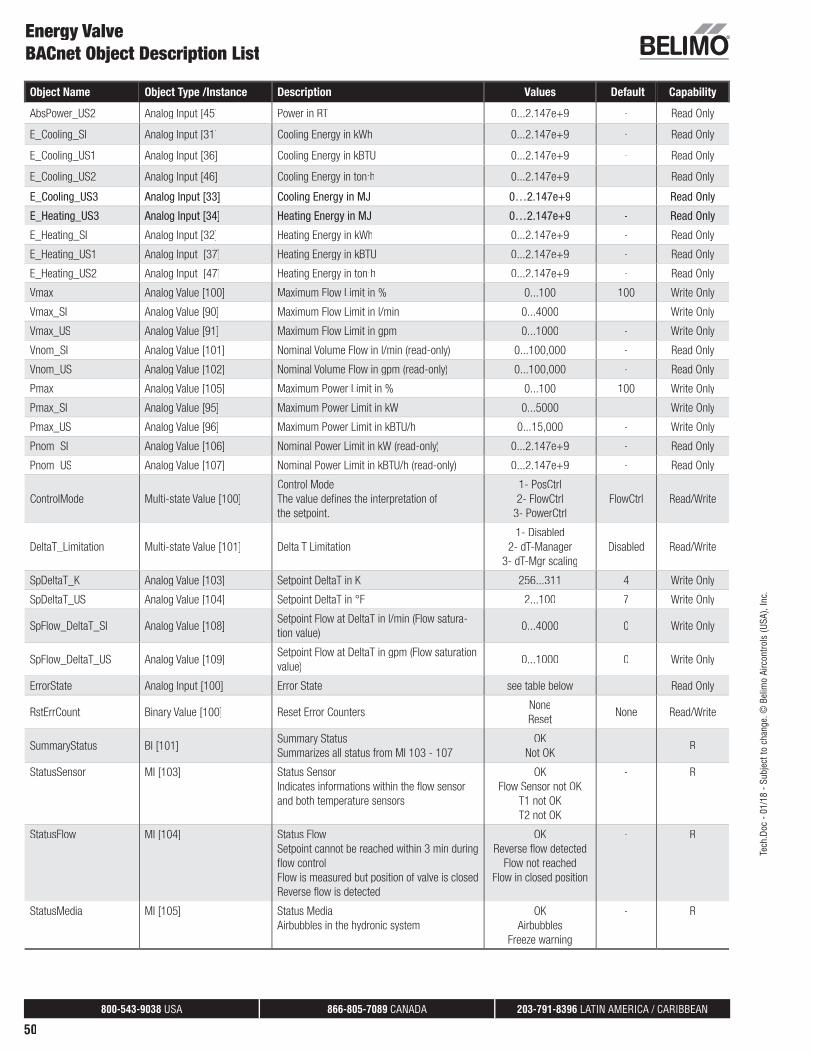
800-543-9038 USA 866-805-7089 CANADA 203-791-8396 LATIN AMERICA / CARIBBEAN
50
Energy ValveBACnet Object Description List
Object Name Object Type /Instance Description Values Default Capability
AbsPower_US2 Analog Input [45] Power in RT 0...2.147e+9 - Read Only
E_Cooling_SI Analog Input [31] Cooling Energy in kWh 0...2.147e+9 - Read Only
E_Cooling_US1 Analog Input [36] Cooling Energy in kBTU 0...2.147e+9 - Read Only
E_Cooling_US2 Analog Input [46] Cooling Energy in ton.h 0...2.147e+9 - Read Only
E_Cooling_US3 Analog Input [33] Cooling Energy in MJ 0…2.147e+9 - Read Only
E_Heating_US3 Analog Input [34] Heating Energy in MJ 0…2.147e+9 - Read Only
E_Heating_SI Analog Input [32] Heating Energy in kWh 0...2.147e+9 - Read Only
E_Heating_US1 Analog Input [37] Heating Energy in kBTU 0...2.147e+9 - Read Only
E_Heating_US2 Analog Input [47] Heating Energy in ton.h 0...2.147e+9 - Read Only
Vmax Analog Value [100] Maximum Flow Limit in % 0...100 100 Write Only
Vmax_SI Analog Value [90] Maximum Flow Limit in l/min 0...4000 - Write Only
Vmax_US Analog Value [91] Maximum Flow Limit in gpm 0...1000 - Write Only
Vnom_SI Analog Value [101] Nominal Volume Flow in l/min (read-only) 0...100,000 - Read Only
Vnom_US Analog Value [102] Nominal Volume Flow in gpm (read-only) 0...100,000 - Read Only
Pmax Analog Value [105] Maximum Power Limit in % 0...100 100 Write Only
Pmax_SI Analog Value [95] Maximum Power Limit in kW 0...5000 - Write Only
Pmax_US Analog Value [96] Maximum Power Limit in kBTU/h 0...15,000 - Write Only
Pnom_SI Analog Value [106] Nominal Power Limit in kW (read-only) 0...2.147e+9 - Read Only
Pnom_US Analog Value [107] Nominal Power Limit in kBTU/h (read-only) 0...2.147e+9 - Read Only
ControlMode Multi-state Value [100]
Control Mode
The value defines the interpretation of
the setpoint.
1- PosCtrl
2- FlowCtrl
3- PowerCtrl
FlowCtrl Read/Write
DeltaT_Limitation Multi-state Value [101] Delta T Limitation
1- Disabled
2- dT-Manager
3- dT-Mgr scaling
Disabled Read/Write
SpDeltaT_K Analog Value [103] Setpoint DeltaT in K 256...311 4 Write Only
SpDeltaT_US Analog Value [104] Setpoint DeltaT in °F 2...100 7 Write Only
SpFlow_DeltaT_SI Analog Value [108]Setpoint Flow at DeltaT in l/min (Flow satura-
tion value)0...4000 0 Write Only
SpFlow_DeltaT_US Analog Value [109]Setpoint Flow at DeltaT in gpm (Flow saturation
value)0...1000 0 Write Only
ErrorState Analog Input [100] Error State see table below - Read Only
RstErrCount Binary Value [100] Reset Error CountersNone
ResetNone Read/Write
SummaryStatus BI [101]Summary Status
Summarizes all status from MI 103 - 107
OK
Not OK- R
StatusSensor MI [103] Status Sensor
Indicates informations within the flow sensor
and both temperature sensors
OK
Flow Sensor not OK
T1 not OK
T2 not OK
- R
StatusFlow MI [104] Status Flow
Setpoint cannot be reached within 3 min during
flow control
Flow is measured but position of valve is closed
Reverse flow is detected
OK
Reverse flow detected
Flow not reached
Flow in closed position
- R
StatusMedia MI [105] Status Media
Airbubbles in the hydronic system
OK
Airbubbles
Freeze warning
- R
Tech
.Doc
- 01
/18
- Sub
ject
to c
hang
e. ©
Bel
imo
Airc
ontro
ls (U
SA),
Inc.

800-543-9038 USA 866-805-7089 CANADA 203-791-8396 LATIN AMERICA / CARIBBEAN
51
Error State Translation
Bit 0: (1) Error Sensor T1
Bit 1: (2) Error Sensor T2
Bit 2: (4) Error Flow Sensor
Bit 3: (8) Actuator cannot move
Bit 4: (16) Flow with closed valve
Bit 5: (32) Air bubbles
Bit 6: (64) Flow not reached
Bit 7: (128) Power not realized
Bit 8: (256) Gear disengaged
Bit 9: (512) Watchdog triggered
Example: “Flow not reached” + “Gear disengaged” = 64 + 256 = 320
Energy Valve -Modbus Description
Modbus General Notes
General information Protocol: Modbus RTU / RS-485
Number of nodes: Max. 32 (without repeater)
Transmission formats: 1-8-N-2, 1-8-N-1, 1-8-E-1, 1-8-O-1, Default: 1-8-N-2
Baud rate: 9,600, 19,200, 38,400, 76,800, Default: 38,400 Baud 115,200 Baud
Terminating resistor: 120 (to be done with external resistor)
Parameterization: through the integrated web server
Register implementation All data is arranged in a table and addressed by 1..n (register) or 0..n-1 (address). Nodistinction is made between data types (Discrete Inputs, Coils, Input Registers and HoldingRegisters). As a consequence, all data can be accessed with the two commands for Holding Register. The commands for Discrete Inputs and Input Registers can be used as an alterna-tive.
Standard commands Read Holding Registers [3]
Write Single Register [6]
Read Discrete Inputs [2]
Read Input Registers [4]
Write Multiple Registers [16]
Energy ValveBACnet Object Description List
Object Name Object Type /Instance Description Values Default Capability
StatusActuator MI [106] Status Actuator
Mechanical overload due to blocked valve, etc.
Gear disengaged button pressed
OK
Actuator cannot move
Gear disengaged
- R
StatusPower MI [107] Status Power
Setpoint cannot be reached within 3 min during
power control
OK
Power not reached
- R
SpRel Analog Output [1]
Setpoint Relative in %
The set point is related either to the position,
the flow (Vmax) or the power (Pmax).
See ControlMode for more information.
0…100 0 Read/Write
Tech
.Doc
- 01
/18
- Sub
ject
to c
hang
e. ©
Bel
imo
Airc
ontro
ls (U
SA),
Inc.

800-543-9038 USA 866-805-7089 CANADA 203-791-8396 LATIN AMERICA / CARIBBEAN
52
Command “Read Discrete Inputs” The command reads one or more bits and can alternatively be used for Register No. 105(Malfunction and Service information). Example: The start address to be used is1664 104 (Register Address) * 16 (Bit) =1664
Interpret values in the registers All values in the register are unsigned integer with exception of Register No. 17/19/22.Signed integers are represented as two’s complement.
Example unsigned integer: Read (Function 03, 1 Register) Value Register No. 12 =0001’1010’1100’10002 = 6,85610
Actual Value = Value * Scaling factor * Unit = 6,856 * 0.01 * m3/h = 68.56 m3/h
Example signed integer Read (Function 03, 1 Register) Value Register No. 17 =1111’1101’1111’00102 = -52610
Actual Value = Value * Scaling factor * Unit = -526 * 0.01 * °C = -5.26 °C
32-Bit Values in two registers Values that exceed 65,535 are stored in two consecutive Registers and have to beinterpreted as “little endian” / LSW (Least Significant Word) first.
Example: Register No. 10 (AbsFlow LowByte) = 14,55110 = 0011’1000’1101’01112
Register No. 11 (AbsFlow HighByte) = 1910 = 0000’0000’0001’00112
AbsFlow = 0000’0000’0001’0011’0011’1000’1101’01112 = 1,259,73510
= 1259.735 l/h
AbsFlow High Byte AbsFlow Low Byte
19 14,551
0000’0000’0001’0011 0011’1000’1101’0111
Math formula:
AbsFlow = ( AbsFlow HighByte * 65,536 ) + AbsFlow LowByte
AbsFlow = ( 19 * 65,536 ) + 14,551 = 1,259,735 = 1259.735 l/h
Energy ValveModbus Description
Number Address Register R/W
1 0 Setpoint [%] R/W
2 1 Override control R/W
3 2 - R
4 3 Actuator type R
5 4 Relative position [%] R
6 5 Absolute position [ °] R
7 6 Relative Flow [%] R
8 7 Absolute flow [UnitSel] LData R
9 8 HData
10 9 Absolute flow [l/s] LData R
11 10 HData
12 11 Absolute flow [gpm] LData R
13 12 HData
Modbus Overview
Tech
.Doc
- 01
/18
- Sub
ject
to c
hang
e. ©
Bel
imo
Airc
ontro
ls (U
SA),
Inc.

800-543-9038 USA 866-805-7089 CANADA 203-791-8396 LATIN AMERICA / CARIBBEAN
53
Energy ValveModbus Overview
Modbus Overview Continuation
Number Address Register R/W
14 13 Setpoint Absolute Flow [UnitSel] LData R
15 14 HData
16 15 Setpoint Analog [V] R
17 16 Temperature 1 [°C] R
18 17 Temperature 1 [°F] R
19 18 Temperature 2 [°C] R
20 19 Temperature 2 [°F] R
21 20 Delta Temperature [K] R
22 21 Delta Temperature [°F] R
23 22 Glycol Concentration [%] R
24 23 Relative power [%] R
25 24 Absolute Power [UnitSel] LData R
26 25 HData
27 26 Absolute Power [kW] LData R
28 27 HData
29 28 Absolute Power [kBTU/h] LData R
30 29 HData
31 30 Energy Cooling [UnitSel] LData R
32 31 HData
33 32 Energy Cooling [kWh] LData R
34 33 HData
35 34 Energy Cooling [kBTU] LData R
36 35 HData
37 36 Energy Heating [UnitSel] LData R
38 37 HData
39 38 Energy Heating [kWh] LData R
40 39 HData
41 40 Energy Heating [kBTU] LData R
42 41 HData
101 100 Series number 1st part R
102 101 Series number 2nd part
103 102 Series number 4th part
104 103 Firmware version R
105 104 Malfunction & Service information R
106 105 Vmax [%] R/W
107 106 Absolute Vmax [l/s] LData R/W
108 107 HData
Tech
.Doc
- 01
/18
- Sub
ject
to c
hang
e. ©
Bel
imo
Airc
ontro
ls (U
SA),
Inc.
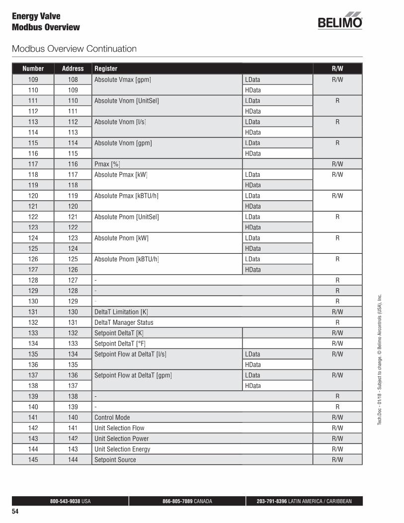
800-543-9038 USA 866-805-7089 CANADA 203-791-8396 LATIN AMERICA / CARIBBEAN
54
Energy ValveModbus Overview
Number Address Register R/W
109 108 Absolute Vmax [gpm] LData R/W
110 109 HData
111 110 Absolute Vnom [UnitSel] LData R
112 111 HData
113 112 Absolute Vnom [l/s] LData R
114 113 HData
115 114 Absolute Vnom [gpm] LData R
116 115 HData
117 116 Pmax [%] R/W
118 117 Absolute Pmax [kW] LData R/W
119 118 HData
120 119 Absolute Pmax [kBTU/h] LData R/W
121 120 HData
122 121 Absolute Pnom [UnitSel] LData R
123 122 HData
124 123 Absolute Pnom [kW] LData R
125 124 HData
126 125 Absolute Pnom [kBTU/h] LData R
127 126 HData
128 127 - R
129 128 - R
130 129 - R
131 130 DeltaT Limitation [K] R/W
132 131 DeltaT Manager Status R
133 132 Setpoint DeltaT [K] R/W
134 133 Setpoint DeltaT [°F] R/W
135 134 Setpoint Flow at DeltaT [l/s] LData R/W
136 135 HData
137 136 Setpoint Flow at DeltaT [gpm] LData R/W
138 137 HData
139 138 - R
140 139 - R
141 140 Control Mode R/W
142 141 Unit Selection Flow R/W
143 142 Unit Selection Power R/W
144 143 Unit Selection Energy R/W
145 144 Setpoint Source R/W
Modbus Overview Continuation
Tech
.Doc
- 01
/18
- Sub
ject
to c
hang
e. ©
Bel
imo
Airc
ontro
ls (U
SA),
Inc.
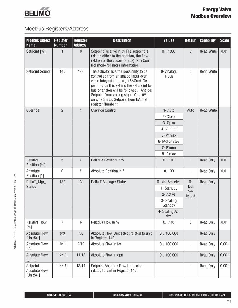
800-543-9038 USA 866-805-7089 CANADA 203-791-8396 LATIN AMERICA / CARIBBEAN
55
Energy ValveModbus Overview
Modbus Registers/Address
Modbus Object Name
Register Number
Register Address
Description Values Default Capability Scale
Setpoint [%] 1 0 Setpoint Relative in % The setpoint isrelated either to the position, the flow(vMax) or the power (Pmax). See Con-trol mode for more information.
0…1000 0 Read/Write 0.01
Setpoint Source 145 144 The actuator has the possibility to becontrolled from an analog input evenwhen integrated through BACnet. De-pending on this setting the setppoint bybus or analog will be followed. Analog:Setpoint from analog signal 0…10Von wire 3 Bus: Setpoint from BACnet,register Number 1
0- Analog,1-Bus
0 Read/Write
Override 2 1 Override Control 1- Auto Auto Read/Write
2- Close
3- Open
4- V’ nom
5- V’ max
6- Motor Stop
7- P’nom
8- P’max
RelativePosition [%]
5 4 Relative Position in % 0…100 - Read Only 0.01
AbsolutePosition [°]
6 5 Absolute Position in ° 0…90 - Read Only 0.01
DeltaT_Mgr_Status
132 131 Delta T Manager Status 0- Not Selected 0-NotSe-
lected
Read Only
1- Standby
2- Active
3- ScalingStandby
4- Scaling Ac-tive
Relative Flow[%]
7 6 Relative Flow in % 0…100 0 Read Only 0.01
Absolute Flow[UnitSel]
8/9 7/8 Absolute Flow Unit select related to unit in Register 142
0…100,000 Read Only
Absolute Flow[l/s]
10/11 9/10 Absolute Flow in l/s 0…100,000 - Read Only 0.001
Absolute Flow[gpm]
12/13 11/12 Absolute Flow in gpm 0…100,000 - Read Only 0.001
SetpointAbsolute Flow[UnitSel]
14/15 13/14 Setpoint Absolute Flow Unit selectrelated to unit in Register 142
- Read Only 0.001
Tech
.Doc
- 01
/18
- Sub
ject
to c
hang
e. ©
Bel
imo
Airc
ontro
ls (U
SA),
Inc.

800-543-9038 USA 866-805-7089 CANADA 203-791-8396 LATIN AMERICA / CARIBBEAN
56
Modbus Object Name
Register Number
Register Address
Description Values Default Capability Scale
Set pointAnalog [V]
16 15 Setpoint Analog in Volt 0.000…10.00V - Read Only
Temperature 1[°C]
17 16 Temperature 1 (remote) in °C -10…+120 - Read Only 0.01
Temperature 1[°F]
18 17 Temperature 1 (remote) in °F 14…248 - Read Only 0.01
Temperature 2[°C]
19 18 Temperature 2 (embedded) in °C -10…+120 - Read Only 0.01
Temperature 2[°F]
20 19 Temperature 2 (embedded) in °F 14…248 - Read Only 0.01
DeltaTemperature °C
21 20 Delta Temperature in °C -500…+500 - Read Only 0.01
DeltaTemperature °F
22 21 Delta Temperature in °F -500…+500 - Read Only 0.01
GlycolConcentration[%]
23 22 Glycol Concentration in % 0…100 - Read Only 0.01
Relative Power[%]
24 23 Relative Power in % 0…100 - Read Only 0.01
Absolute Power[UnitSel]
25/26 24/25 Absolute Power for Unit Selected inPower Register 143
- Read Only 0.001
Absolute Power[kW]
27/28 26/27 Power in kW 0…2.147e+9 - Read Only 0.001
Absolute Power[kBTU/h]
29/30 28/29 Power in kBTU/h 0…2.147e+9 - Read Only 0.001
Energy Cooling[UnitSel]
31/32 30/31 Cooling Energy unit which is selected inRegister 144
- Read Only 1
Energy Cooling[kWh]
33/34 32/33 Cooling Energy in kWh 0…2.147e+9 - Read Only 1
Energy Cooling[kBTU]
35/36 34/35 Cooling Energy in kBTU 0…2.147e+9 - Read Only 1
Energy Heating[UnitSel]
37/38 36/37 Heating Energy unit which is selected inRegister 144
0…2.147e+9 - Read Only 1
Energy Heating[kWh]
39/40 38/39 Heating Energy in kWh 0…2.147e+9 - Read Only 1
Energy Heating[kBTU]
41/42 40/41 Heating Energy in MJ 0…2.147e+9 - Read Only 1
Vmax [%] 106 105 Maximum Flow Limit in % 0…100 100 Read/Write 0.01
Vmax [l/s] 107/108 106/107 Maximum Flow Limit in l/s 0…4000 - Read/Write 0.001
Vmax [gpm] 109/110 108/109 Maximum Flow Limit in gpm 0…1000 - Read/Write 0.001
Vnom [UnitSel] 111/112 110/111 Nominal volume which is selected inRegister 142
- - Read Only 0.001
Vnom [l/s] 113/114 112/113 Nominal Volume in l/min 0…100,000 - Read Only 0.001
Vnom [gpm] 115/116 114/115 Nominal Volume in gpm 0…100,000 - Read Only 0.001
Energy ValveModbus Overview
Tech
.Doc
- 01
/18
- Sub
ject
to c
hang
e. ©
Bel
imo
Airc
ontro
ls (U
SA),
Inc.

800-543-9038 USA 866-805-7089 CANADA 203-791-8396 LATIN AMERICA / CARIBBEAN
57
Modbus Object Name
Register Number
Register Address
Description Values Default Capability Scale
Pmax [%] 117 116 Maximum Power Limit in % 0…100 100 Read/Write 0.01
Pmax [kW] 118/119 117/118 Maximum Power Limit in kW 0…5000 - Read/Write 0.001
Pmax [kBTU/h] 120/121 119/120 Maximum Power Limit in kBTU/h 0…15,000 - Read/Write 0.1
Pnom [UnitSel] 122/123 121/122 Nominal Power Unit which is selected inRegister 143
- Read Only 0.001
Pnom [kW] 124/125 123/124 Nominal Power in kW 0…2.147e+9 - Read Only 0.001
Pnom [kBTU/h] 126/127 125/126 Nominal Powerin kBTU/h 0…2.147e+9 - Read Only 0.001
ControlMode 141 140 The value defines the interpretation ofthe setpoint
0- PosCtrl Flow-Ctrl
Read/Write 1
1- FlowCtrl
2- PowerCtrl
DeltaT_Limitation
131 130 Delta T Limitation 0- Disabled (off) Dis-abled
Read/Write 1
1- dT- Manager
2- dT ManagerScaling
Set point DeltaT[K]
133 132 Setpoint Delta T in K 0…+500 4 Read/Write 0.01
Set point DeltaT[°F]
134 133 Setpoint Delta T in °F 2…100 10 Read/Write 0.01
Set point Flow_DeltaT [l/s]
135/136 134/135 Setpoint Flow at Delta T in l/s (Flowsaturation value)
0…4000 0 Read/Write 0.001
Set point Flow_DeltaT [gpm]
137/138 136/137 Setpoint Flow at Delta T in gpm (Flowsaturation value)
0…1000 0 Read/Write 0.001
Unit Select Flow 142 141 Selection of flow Unit Defines Registers8/9, 14/15, 111/112
0- m3/s gpm Read/Write
1- m3/h
2- l/s
3- l/min
4- l/h
5- gpm
Unit SelectPower
143 142 Selection of Power unit defines unitRegister No. 25/26, 122/123
0- W kBTU/h Read/Write
1- kW
2- BTU/h
3- kBTU/h
4- Tons
Unirt SelectEnergy
144 143 Selection of Energy unit defines unitRegister No. 31/32, 37/38
0- J kBTU Read/Write
1- kWh
2- MWh
3- kBTU
4- tonh
5- MJ
6- GJ
ErrorState 105 104 Error State
Energy ValveModbus Overview
Tech
.Doc
- 01
/18
- Sub
ject
to c
hang
e. ©
Bel
imo
Airc
ontro
ls (U
SA),
Inc.

800-543-9038 USA 866-805-7089 CANADA 203-791-8396 LATIN AMERICA / CARIBBEAN
58
Energy ValveTerms and Conditions of Sale and Warranty
Terms and Conditions
General 1.1. The following Terms and Conditions of Sale (“Terms”) apply
to the sale of products described in this Product Guide (“Products”). As used herein, “Seller” or “Belimo” refers toBelimo Aircontrols (USA) Inc. or Belimo Aircontrols (CAN) Inc., as applicable, and “Client” refers to the individual or businessentity that purchases the Products from Seller. These Terms shall apply unless the parties mutually agree to different terms and memorialize such agreement in writing signed by both Client and Seller.
II. Price 2.1. The Seller’s price for Products (the “Price”) is net, F.O.B.
Point of Origin, and is calculated in US currency for sales made by Belimo Aircontrols (USA), Inc. and calculated in Canadian currency for sales made by Belimo Aircontrols (CAN) Inc.
2.2. The Price, unless otherwise agreed upon, does not includefreight and packaging (wooden crates, pallets, etc), the costs of which will be charged to Client at cost for each shipment and shall be payable with payment of the Price.
2.3. Orders for Products with a net value of less than US $300(CAN $300) will be subject to a US $20 (CAN $20) handling fee (the “Handling Fee”). The Handling Fee will not be charged for orders of Products with a net value equal to or greater thanUS $300 (CAN $300) or for Products ordered through Seller’seCommerce ordering system at: www.belimo.com.
2.4. Seller reserves the right to make partial deliveries of ordersof Products, each of which deliveries may be invoiced separately by Seller.
2.5. The Price does not include charges for wiring diagrams,installation, and commissioning, which will be charged to Client separately and will be payable on demand.
III. Payment 3.1. Invoices are payable in US currency for sales made by
Belimo Aircontrols (USA), Inc. and in Canadian currency for sales made by Belimo Aircontrols (CAN) Inc. and are due no later than 30 days from the date of invoice, without anydeductions.
3.2. If Client fails to pay the entire invoice balance within 60 daysfrom the date of the invoice, Client will be subject to an interestcharge of 2% per month (or the maximum rate permitted by law,whichever is less) on the outstanding unpaid balance due to Seller.
3.3. Clients who maintain outstanding balances for 45 days or more after the date of invoice may be subject to restrictedshipments of Products or may be required to pay for all futuredeliveries of Products on a cash-on-delivery basis.
IV. Title and Risk 4.1. Title to all Products shall remain with Seller and shall not
pass to Client until Seller has received full payment for the Products.
VV. Damage or Loss in Transit 5.1. Seller assumes no liability for damage or loss of shipment
of Products, which risk shall at all times remain with the carrier.All shipments must be unpacked and examined by Client immediately upon receipt. Any external evidence of loss or damage must be noted on the freight bill accompanying the shipment of Products or carrier’s receipt and signed by thecarrier’s agent at the time of delivery. Failure to do so will resultin the carrier’s refusal to honor any claim relating to damage of Products. Client must also notify Seller of such damage byproviding Seller with a copy of the freight bill or damage reportso that Seller can file a claim for loss or damage in transit withthe carrier. If the damage does not become apparent until theshipment is unpacked, Client must make a request for inspection
r by the carrier’s agent and file with the carrier within 15 days afterreceipt of product and notify Seller of the same. Seller is notliable for consequential damage to Client’s property or a third-party’s property resulting from the installation of damagedProducts.
VI. Delivery 6.1. Seller undertakes to make every attempt to adhere to its
stated delivery parameters and to make a timely delivery of the Products but does not guarantee any delivery specifications.Each contract entered into for the purchase of Products is notcancelable nor is Seller liable for any direct or indirect losses that may arise, for any reason whatsoever, due to Seller’s failure to meet any stated or assumed delivery schedules.
VII. Return of Goods 7.1. Products received by Client cannot be returned unless: (i)
Client alerts Seller that it intends to return such Products, (ii)Seller agrees to accept the return of such Products, (iii) Client obtains a Return Material Authorization (“RMA”) number fromSeller for the return of such Products, and (iv) Client follows all
r return instructions provided by the Seller. The RMA numbermust be clearly written on the outside of all packaging for any
r returned Products. Only Products returned to the properAlocation as instructed by Seller and identified with an RMA
number will be considered for credit. 7.2. Only Products that are returned in original packaging may
be accepted for return. All returned Products must be shipped to Seller at Client’s cost. Such returned Products must be received within 1 yr. from original sale date, in as-new condition,adequate for resale as new Products to qualify for credit. Client will be responsible for payment of a restocking charge for all returned Products in an amount no less than 20% of the invoicevalue of the Products (“Restocking Charges”). Product receiveddamaged or showing evidence of having been installed will be refused or assessed a higher restocking charge. Custom kitsdesigned to a Client’s unique specifications are not returnable. If Client requests product to be returned to them, the Client will be responsible for return shipping charges. See specific productliterature for exclusions or exceptions.
7.3. Returns that result from Seller errors will be credited in fulland will not be subject to Restocking Charges.
VIII. WarrantyVIII.A 5-year Warranty 8.1. Products that are listed in this Product Guide as carrying a
5-year warranty to a location in the United States or Canada shall carry a 5-year warranty. The 5-year warranty is unconditional for the first two years from the date of production of theProducts. After the first two years from the date of Sale, thewarranty shall be conditional and the warranty coverage shall not apply to damage to Products caused by ordinary wear and tear, negligence or improper use by Client, or other causes
f beyond the control of the Seller. Product specific terms off warranty with regard to warranty period or conditions of
warranty may apply to certain specified Products as stated in the documentation for those Products.
VIII.B 2-year Conditional warranty 8.2. Products that are listed in this Product Guide as carrying a
2-year warranty to a location in the United States or Canada shall carry a 2-year warranty. The 2-year warranty is conditional and the warranty coverage shall not apply to damage to
r Products caused by ordinary wear and tear, negligence orfimproper use by Client, or other causes beyond the control of
the Seller. Product specific terms of warranty with regard towarranty period or conditions of warranty may apply to certain specified Products as stated in the documentation for thoseProducts.
Tech
.Doc
- 01
/18
- Sub
ject
to c
hang
e. ©
Bel
imo
Airc
ontro
ls (U
SA),
Inc.
800-543-9038 USA 866-805-7089 CANADA 203-791-8396 LATIN AMERICA / CARIBBEAN
59
Energy ValveTerms and Conditions of Sale and Warranty
VVIII.C General Warranty Terms 8.3. Seller’s warranty may be null and void in the event of any:
(a) modification or unauthorized repairs of Products by Client,(b) unauthorized incorporation or integration of Products into or with Client’s equipment, (c) use of Products in an unauthorizedmanner, or (d) damage to Products not caused by Seller.
8.4. Client must promptly notify Seller of Products’ allegeddefect and provide Seller with other evidence and documenta-tion reasonably requested by Seller. Before removing Productsfrom service, Client should contact a Seller-authorized supporttechnician by calling Belimo customer service. The contactinformation for Belimo customer service is listed on the back page of Belimo’s Product Guide and Price List (“PGPL”) or maybe found at www.belimo.com. Belimo customer service willwork with field technicians to troubleshoot problems. Manyproblems can be resolved over the phone.
8.5. If a problem cannot be resolved over the phone, an RMA number will be issued by Seller for return of the Products. Prior to returning any Products under a warranty, Client must obtainan RMA number from Seller, along with shipping instructions for the return. The RMA number must be clearly written on the outside of the box containing the returned Products. OnlyProducts returned to the proper location and identified with anRMA number will be accepted by the Seller.
8.6. All returned Products should be packaged appropriately toprevent further damage. Seller reserves the right to refuse anyreturned material if improperly packaged or labeled (without anRMA number). Products returned without proper RMA docu-mentation will void Seller’s warranty.
8.7. Products found to be defective for which a warranty isapplicable will either be replaced or repaired at the Seller’s dis-cretion. Seller is not responsible for charges that Client mayincur as a result of the removal or replacement of Products.
8.8. Repaired or replacement Products are shipped from Seller via ground shipment. Other shipping methods are available atthe sole expense of the Client.
8.9. Repaired, replaced or exchanged Products will carry a war-ranty for a period of time equal to the greater of: (i) the remain-der of the original 5-year warranty or 2-year warranty that was applicable to the repaired, replaced or exchanged Products, or (ii) six months, effective from the date the repaired, exchanged or replaced Products are shipped by Seller (the “ReplacementWarranty Period”).
8.10. Advanced replacement Products for Products coveredunder warranty may be obtained from Seller after the Belimocustomer service troubleshooting process has been completed. For industrial products (such as butterfly valves), a purchaseorder is required. The purchase order will be credited upon thereceipt and verification by Seller of the returned defectiveProducts. For non-industrial products, an invoice will be issuedand shall be due and payable if the returned Products are not received by Seller within 60 days from the date that the replace-ment Products are shipped. Additional charges may apply if thenature of the problem has been misrepresented by Client.
8.11. Both the conditional and unconditional warranties cover the Products only, and do NOT cover labor associated with thetroubleshooting, removal or replacement of such Products.
8.12. New Products ordered in an attempt to circumvent thewarranty process may NOT be reimbursed if, upon receipt of returned Products, it is determined that the defect in thereturned Products is actually field related, or the Products havebeen returned for cosmetic reasons only.
8.13. Advanced replacement Products for butterfly valve actua-tors may not be new, but have been verified by the Seller for electrical and mechanical operation. Such Products carry thefull warranty for the entire Replacement Warranty Period.
IX. No Warranty for Non-HVAC Application 9.1. All Seller warranties shall extend only to HVAC use of the
Products. If Products are used in non-HVAC applications (e.g.,aircraft, industrial processes, etc.), Seller’s warranties shall not cover such Products. Client will be solely responsible for anydamage to or malfunction of Products or for any damage result-ing from such use of Products.
X. Liability Disclaimer 10.1. These Terms constitute the entire understanding and
agreement between Seller and Client regarding the warranties that cover Products and supersedes all previous understand-
r ings, agreements, communications and representations. Sellershall not be responsible for and Client does not have any right
rto make any claim for damage that occurs to any property other than Products. Seller shall in no way be responsible for any
fcosts incurred by Client in the determination of the causes of rdamage to any of Client’s property, for expert opinions, or for fany punitive or special, incidental or consequential damages of
any kind whatsoever. Seller’s warranty is extended to the Client only and is non-transferrable.
r 10.2. Seller shall not be liable for any damage resulting from orfcontributed by Client or third parties acting within the scope of
responsibility of Client or such third party when: 1. Products are used for non-HVAC applications, such as in
aircrafts, industrial processes, etc.; 2. Client uses the Products without complying with applicable
law or institutional regulations or Belimo data and installationsheets or Client uses the Products without following good industry practice;
3. Products are used by personnel who have not received suitable instruction; or 4. Products are modified or repaired without the written
approval of Seller.r When requested to do so, Client shall immediately release Seller
in full from any possible third party claims resulting in connec-tion with the circumstances listed above. This also applies to claims in connection with product liability.
r 10.3. If Client becomes aware that any third party has made orappears likely to make any claim regarding Products (including,without limitation, regarding Product defects or rights infringedby Products), then Client shall immediately inform Seller andafford to Seller all assistance that Seller may require to enforceits rights and defend such claim.
XI. Proper Law and Jurisdiction 11.1. All sales of Products under these Terms and the warran-
ties described herein shall be governed by the laws of the State of Connecticut, and the parties agree to submit to the exclusive jurisdiction of the Federal and state courts located in the State of Connecticut with respect to any dispute arising from the sub-ject matter hereof. The parties hereby waive all rights to a jury
r trial in connection with any claims relating to the subject matterhereof.
Tech
.Doc
- 01
/18
- Sub
ject
to c
hang
e. ©
Bel
imo
Airc
ontro
ls (U
SA),
Inc.

800-543-9038 USA 866-805-7089 CANADA 203-791-8396 LATIN AMERICA / CARIBBEAN
60
Energy ValveGlossary of Terms
T Measured differential temperature between water supply and return.
Analog A linear signal from one device to another. It used to move or read values. It is used by a controller to modulate an actuator. Typicalanalog signal range is 2-10 VDC, 0-10 VDC, or 4-20 mA.
BACnet A standard world-wide communication protocol that is used in buildingautomation. BACnet uses two common communication mechanisms, BACnet IP which communicates over Ethernet networks. BACnet MS/TP communicates over 2 or 3-wire RS485 networks.
BMS (Building Management System) A computer-based control system installed in buildings to control and monitor the building’s mechanical and electrical equipment.
CCV (Characterized Control Valve)A Belimo patented ball valve with characterizing disc that provides equal percentage fl ow characteristic with high rangeability, zero leakage, and high close-off.
DDC (Direct Digital Control) A controller with software to operate control valves, dampers and other devices.
Delta T Limit Value A setting used by the Delta T Manager to limit coil overfl ow.
Delta T Manager A patented fl ow limiting logic applied to the Energy Valve Control Modes.
dT Manager An option in the Delta T Manager logic that produces a fi xed dT setpoint.
dT Manager Scaling An option in the Delta T Manager logic that produces a variably scaled dT setpoint.
delta T (T) The difference in the supply and return temperatures of a coil.
dT setpoint The set point used by the Delta T Manager logic. When used with dT Manager it is a fi xed setting. When used with dT Manager Scaling it becomes a calculated variable over a scaled range.
Flow Saturation Limit Value / Flow Saturation A setting used with dT Manager Scaling to reset the Delta T Limiting Value and create a variable, dT setpoint.
Ghost Energy Leaky control valves can create ghost heating and cooling demand and excess ventilation, which comes with a need to dehumidify or preheat. Also, there is ghost pumping for the additional chilled water and heating water fl ows along with ghost heating and cooling. A 1% leakage creates a 5 to 10% loss of energy.
MP-Bus (MP) A Belimo communication protocol. The ZTH US tool uses this protocol to view and change actuator settings.
P’max The maximum thermal power setting.
P’nom The maximum thermal power of the heat exchanger.
V’max The maximum valve fl ow setting.
V’nom The maximum valve fl ow.
Tech
.Doc
- 01
/18
- Sub
ject
to c
hang
e. ©
Bel
imo
Airc
ontro
ls (U
SA),
Inc.

www.EnergyValve.com
Belimo Americas
USA, Latin America, and the Caribbean: www.belimo.us
Canada: www.belimo.ca
Brazil: www.belimo.br
Belimo Worldwide: www.belimo.com