Embed Size (px)
Citation preview

Comparison of up-flow cooling units in
data center design.
Hot Aisle / Cold Aisle (up-flow)
Hot Aisle / Cold Aisle (downflow)

Comparison of traditional and up-flow cooling units
down-flow Cooling units (cold aisle view)
down-flow Cooling units (hot aisle view)
up-flow Cooling units (cold aisle view)
up-flow Cooling units (hot aisle view)
Down-flow units direct conditioned air under the floor.
Down-flow units intake hot exhaust air from the room via direct
to the intake or plenum.
Up-flow units directs conditioned air into the room through the
top of the cooling unit or via a duct running into the cold aisle.
Up-flow units intake hot exhaust air from the bottom of the floor.
The units are designed to be installed in the hot aisle.
Below is a graphical illustration of the operation of the two types of cooling units discussed in this
document. Both units are designed with specific installation designs and are described beneath
each graphic.

Room Specifications
Physical Space
Dimensions: 40′ Wide by 60′ Long
Concrete slab floor
Ceiling height from raised floor: 14′
2403 sq. ft traditional raised floor data center
IT Specifications
7.2 kW per enclosure
Total IT Load = 459kW
64 Racks at 44 RMU (1408 servers @ 2U) 2240 Ports (servers * 2 ports)
Hot Aisle / Cold Aisle
Hot Aisle / Cold Aisle (up-flow)
Up-flow CRAC units are designed to be placed in parallel to the hot

Hot Aisle / Cold Aisle
Hot Aisle / Cold Aisle (up-flow)
Hot Aisle / Cold Aisle configuration shows low intake temps in
the cold aisle and lower exhaust temps in the hot aisle. The
overall room environment is very inconsistent.
Hot Aisle / Cold Aisle with up-flow units show cold aisle tem-
peratures considerably higher and more varied than
traditional CRAC units. The outer perimeter of the room is
more consistent however.
Shown are two images from the CFD model with a thermal
plane 3” above the base of the enclosures. The thermal plane
is a heat map used to indicate inconsistent temperatures, hot
air recirculation and by-pass air conditions

Hot Aisle / Cold Aisle
Hot Aisle / Cold Aisle (up-flow)
Hot Aisle / Cold Aisle configuration shows an increase in cold
aisle temperatures indicating the hot exhaust air is recircu-
lating into the cold aisle. Additionally, the hot aisle tempera-
tures are more varied due to by-pass conditioned air reducing
hot aisle temperatures.
Shown are two images from the CFD model with a thermal
plane 45” above the base of the enclosures. The thermal plane
is a heat map used to indicate inconsistent temperatures, hot
air recirculation and by-pass air conditions
Up-flow configuration cold aisle temperatures remain similar to
the lower plane. Hot aisle temperatures are more varied due to
by-pass conditioned air reducing hot aisle temperatures.

Hot Aisle / Cold Aisle
Hot Aisle / Cold Aisle (up-flow)
Shown are two images from the CFD model with a thermal
plane 81” above the base of the enclosures. The thermal plane
is a heat map used to indicate inconsistent temperatures, hot
air recirculation and by-pass air conditions
Temperatures in the cold aisle are lower than the middle
plane demonstrated. This is likely due to a high velocity of
airflow in the cold aisle creating a vertical by-pass air
situation. Hot aisle temperatures are further evidence that
the conditioned air is mixing in the hot aisle reducing the
overall temperatures.
Cold aisle temperature variances at the top of the enclosure
are in excess of safe IT equipment operations. The recircula-
tion of hot exhaust air is flowing to the equipment intakes
at the top of the enclosures. This condition is known as “top
-third” where the upper RMU of the enclosure are unusable
for equipment.
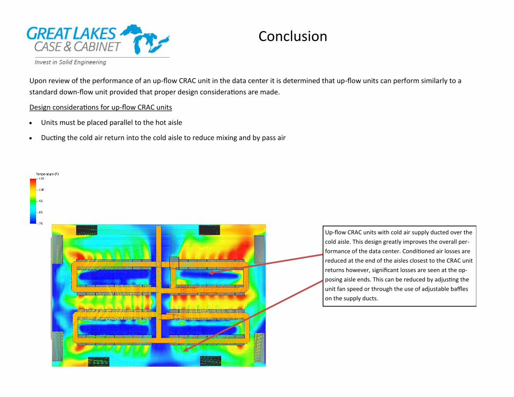
Upon review of the performance of an up-flow CRAC unit in the data center it is determined that up-flow units can perform similarly to a
standard down-flow unit provided that proper design considerations are made.
Design considerations for up-flow CRAC units
Units must be placed parallel to the hot aisle
Ducting the cold air return into the cold aisle to reduce mixing and by pass air
Up-flow CRAC units with cold air supply ducted over the
cold aisle. This design greatly improves the overall per-
formance of the data center. Conditioned air losses are
reduced at the end of the aisles closest to the CRAC unit
returns however, significant losses are seen at the op-
posing aisle ends. This can be reduced by adjusting the
unit fan speed or through the use of adjustable baffles
on the supply ducts.
Conclusion

Great Lakes
Recommended Designs for Up-flow Units
Design One (Partial Cold Aisle Containment—End of Row Doors)
When up-flow units are used in conjunction with ducted cold air supply it is recommended that
the end of the row in the cold aisle have containment doors installed to prevent cold air from
travelling away from the IT equipment intakes into either the hot aisle or the back to the unit
returns.
This design does not completely segregate the cold and hot exhaust air but does improve the
cold aisle temperatures significantly.
Partial Cold Aisle Containment Infrastructure
Description GL Part No. Description
Enclsoure
GL840ES-2448MS GL840ES-2448MS 44RMU enclosure 84” H x 24” W x 48” D (mesh front and rear doors)
Outside the enclosure
End of Row Containment doors ACD840ES Aisle Containment Doors for 78"ES Enclosure; Supports 48-72" aisle width
Inside the enclosure
Blanking “Filler Panels” installed in any unused RMU 3.50-FPTL19 3.50"H tool-less filler panel for 19" mounting on M6 rails, 2 RMU
Brush grommet installed in cable knockouts BGT Brush Grommet Kit for top cable pass through knockouts on ES Enclosure
Brush grommet kits installed along the rails BGRK24 Brush Grommet Kit designed for 24"W x 78" and 84" ES enclosures