Embed Size (px)
DESCRIPTION
omp40 renishaw manual
Citation preview

Programming manualH-2000-6031-0C-A
Inspection Plus software

© 1995–2003 Renishaw plc. All rights reserved.
Renishaw® is a registered trademark of Renishaw plc.
This document may not be copied or reproduced in whole or in part, or transferred to any other mediaor language, by any means, without the prior written permission of Renishaw.
The publication of material within this document does not imply freedom from the patent rights ofRenishaw plc.
Disclaimer
Considerable effort has been made to ensure that the contents of this document are free frominaccuracies and omissions. However, Renishaw makes no warranties with respect to the contents ofthis document and specifically disclaims any implied warranties. Renishaw reserves the right to makechanges to this document and to the product described herein without obligation to notify any person ofsuch changes.
Trademarks
All brand names and product names used in this document are trade names, service marks,trademarks, or registered trademarks of their respective owners.
Renishaw part no: H-2000-6031-0C-A
First issued: 07.1995
Revised: 03.199703.200204.2003

Form 1
EQUIPMENT REGISTRATION RECORDPlease complete this form (and Form 2 overleaf if applicable) after the Renishaw equipment has been installed on yourmachine. Keep one copy yourself and return a copy to your local Renishaw Customer Support office (refer to the manual forthe address and telephone number). The Renishaw Installation Engineer should normally complete these forms.
MACHINE DETAILS
Machine description..................................................................…………….........................................................
Machine type........................................................……………….........................................................................
Controller................................……………………….............................................................................................
Special control options.............................................................................….......................................….............
....................................................................................................................………………………………..............
....................................................................................................................………………………………..............RENISHAW HARDWARE
Inspection probe type .......................................
Interface type ...................................................
Tool setting probe type ...................................
Interface type ...................................................
RENISHAW SOFTWARE
Inspection disk(s)......................................……...............
..........................................................................…...........
.............................................................................…........
Tool setting disk(s) ..............................................…......
..................................................................................…...
.........................................................................................SPECIAL SWITCHING M CODES (OR OTHER) WHERE APPLICABLE
Switch (Spin) probe on ....................................
Switch (Spin) probe off ...................................
Start/Error signal ...............................................
Dual systems only
Switch on inspection probe .......................................
Switch on tool setting ...............................................
Other ..........................................................................
.......................................................................................ADDITIONAL INFORMATION Tick box if Form 2 overleaf
has been filled in.
Customer's name………..................................................................
Customer's address..……................................................................
.....................................….................................................................
.........................................................................................................
…......................................................................................................
Customer's tel. no..........................……..........................................Customer's contact name…………..................................................
Date installed ..........…...........................
Installation engineer …............................
Date of training........................................

Form 2
SOFTWARE DEVIATION RECORD
Standard Renishaw kit no. Software disk nos.
Reason for deviation
Software no. andmacro no.
Comments and corrections
The software product for which these changes are authorised is subject to copyright.
A copy of this deviation sheet will be retained by Renishaw plc.
A copy of the software amendments must be retained by the customer – they cannot be retained byRenishaw plc.

Cautions I
Publication No. H-2000-6031
Caution � Software safetyThe software you have purchased is used to control the movements of a machine tool. Ithas been designed to cause the machine to operate in a specified manner under operatorcontrol, and has been configured for a particular combination of machine tool hardwareand controller.
Renishaw have no control over the exact program configuration of the controller withwhich the software is to be used, nor of the mechanical layout of the machine. Therefore,it is the responsibility of the person putting the software into operation to:
● ensure that all machine safety guards are in position and are correctly workingbefore commencement of operation;
● ensure that any manual overrides are disabled before commencement of operation;
● verify that the program steps invoked by this software are compatible with thecontroller for which they are intended;
● ensure that any moves which the machine will be instructed to make under programcontrol would not cause the machine to inflict damage upon itself or upon anyperson in the vicinity;
● be thoroughly familiar with the machine tool and its controller and know the locationof all emergency stop switches.
!

II
Publication No. H-2000-6031
This page is intentionally left blank
Table of contents III
Publication No. H-2000-6031
Table of contents
Before you begin
Before you begin................................................................................................................. 1
Measurement values used in this manual .......................................................................... 1
List of associated publications ............................................................................................ 2
About the Inspection Plus software .................................................................................... 2
Software kit ......................................................................................................................... 2Floppy disk assembly A-4012-0518 ............................................................................ 2
Macro memory requirements.............................................................................................. 3File 40120519 .............................................................................................................. 3File 40120520 .............................................................................................................. 4File 40120521 .............................................................................................................. 4File 40120727 .............................................................................................................. 5
Renishaw customer services .............................................................................................. 5Calling a Renishaw subsidiary office ........................................................................... 5
Using the software with multi-buffer options....................................................................... 6Fanuc 15M-A02B-0094-J986 ...................................................................................... 6
Chapter 1 Getting started
Why calibrate a measurement probe?............................................................................. 1-2
Calibrating in a bored hole............................................................................................... 1-2
Calibrating in a ring gauge............................................................................................... 1-3
Calibrating the probe length............................................................................................. 1-3
Calibration cycles............................................................................................................. 1-3
Chapter 2 Installing the software
Installing the software ...................................................................................................... 2-2
#506 back-off distance..................................................................................................... 2-2
Settings macro O9724 ..................................................................................................... 2-3

IV Table of contents
Publication No. H-2000-6031
Chapter 3 Optional inputs
Optional inputs ................................................................................................................. 3-2
Chapter 4 Variable outputs
Variable outputs - chart 1................................................................................................. 4-2
Variable outputs - chart 2................................................................................................. 4-3
Chapter 5 Protected positioning cycles
Protected positioning (probe trigger monitor) (O9810) .................................................... 5-2
Chapter 6 Calibration cycles
Calibration cycles - an overview ...................................................................................... 6-2
Calibrating the probe length (O9801) .............................................................................. 6-3
Calibrating the stylus X and Y offsets (O9802)................................................................ 6-5
Calibrating the stylus ball radius (O9803)........................................................................ 6-8
Calibrating the vector stylus ball radius (O9804)........................................................... 6-11
Example 1 - Full calibration in an internal feature ......................................................... 6-15
Example 2 - Full calibration on an external feature ....................................................... 6-17
Chapter 7 Measuring cycles
X Y Z single surface measurement (O9811) ................................................................... 7-2
Web/pocket measurement (O9812)................................................................................. 7-5
Bore/boss measurement (O9814) ................................................................................... 7-9
Finding an internal corner (O9815)................................................................................ 7-13
Finding an external corner (O9816)............................................................................... 7-17
Chapter 8 Vector measuring cycles
Angled single surface measurement (O9821) ................................................................. 8-2
Angled web or pocket measurement (O9822)................................................................. 8-5
3-point bore or boss measurement (O9823) ................................................................... 8-9
Table of contents V
Publication No. H-2000-6031
Chapter 9 Additional cycles
4th axis X measurement (O9817).................................................................................... 9-2
4th axis Y measurement (O9818).................................................................................... 9-5
Bore/boss on PCD measurement (O9819)...................................................................... 9-8
Stock allowance (O9820)............................................................................................... 9-11
Storing multi-stylus data (O9830) .................................................................................. 9-16
Loading multi-stylus data (O9831)................................................................................. 9-20
Spinning the probe on (O9832) ..................................................................................... 9-23
Spinning the probe off (O9833) ..................................................................................... 9-24
Determining feature-to-feature data in the XY plane (O9834)....................................... 9-25
Determining feature-to-feature data in the Z plane (O9834) ......................................... 9-29
Updating the SPC tool offset (O9835) ........................................................................... 9-33
Optimising a probing cycle (O9836) .............................................................................. 9-35
Angle measurement in the X or Y plane (O9843).......................................................... 9-38
Chapter 10 Macro alarm list
Fanuc 0M controller alarms ........................................................................................... 10-2
Mazak M32 controller alarms......................................................................................... 10-2
General alarm list........................................................................................................... 10-2
Optimisation macro only (O9836) alarms ...................................................................... 10-5
Appendix A Example job
Introduction ......................................................................................................................A-2
Probe operations..............................................................................................................A-3
Appendix B Features, cycles and limitations of the Inspection Plussoftware
Features of the Inspection Plus software.........................................................................B-2
Cycles ..............................................................................................................................B-2
Limitations........................................................................................................................B-3Mazak M32 controller ...............................................................................................B-4Fanuc 10/11/12/15M controllers ...............................................................................B-4

VI Table of contents
Publication No. H-2000-6031
Fanuc 6M controller ..................................................................................................B-4Fanuc 0M controller ..................................................................................................B-4Fanuc 16M - 18M controllers....................................................................................B-4
Limitations when using vector cycles O9821, O9822 and O9823...................................B-4Use of 3-point bore/boss macro O9823....................................................................B-5
Mathematical precision ....................................................................................................B-5
Effect of vector calibration data on results.......................................................................B-5
Appendix C Settings macro details
Macro G65P9724.............................................................................................................C-2
Appendix D Tolerances
Tolerances .......................................................................................................................D-2
True position tolerances ..................................................................................................D-3
Appendix E Experience values Ee
Experience values Ee ......................................................................................................E-2
Reason for using this option ............................................................................................E-2
Appendix F Additional spare tool offsets
Additional spare tool offsets............................................................................................. F-2
Appendix G Printing a macro output
Example of printing a macro output ................................................................................ G-2
Appendix H Output flow (bore/boss and web/pocket cycles)
Output flow (bore/boss and web/pocket cycles) ..............................................................H-2
Table of contents VII
Publication No. H-2000-6031
Appendix I Use of macro variables
Local variables .................................................................................................................. I-2
Common variables ............................................................................................................ I-2
Common retained variables.............................................................................................. I-3
Appendix J Tool offset macros O9732 and O9723
Introduction ...................................................................................................................... J-2
Editing macro O9732 ....................................................................................................... J-2
Editing macro O9723 ....................................................................................................... J-2
Appendix K General probing applications
Example 1 - Part identification .........................................................................................K-2
Example 2 - Probe measure every nth component .........................................................K-3
Appendix L One-touch measuring
Glossary of terms - abbreviations and definitions

VIII Table of contents
Publication No. H-2000-6031
This page is intentionally left blank

Before you begin 1
Publication No. H-2000-6031
Before you begin
This programming manual contains detailed information about how to use the InspectionPlus software for programming, operating and controlling your machine tools.
Split into ten self-contained chapters, the manual is structured to provide the informationthat you require to use the Inspection Plus software effectively:
● Chapter 1 explains why your probe must be calibrated before you start using it.
● Chapter 2 describes how to install and customise the Inspection Plus software onyour machine.
● Chapter 3 provides a complete list of the optional inputs that are required by someof the macro cycles.
● Chapter 4 provides a complete list of the optional outputs that are produced bysome of the macro cycles.
● Chapter 5 describes how to use the protected positioning macro (O9810). Whencorrectly used, this macro prevents damage to the probe stylus in the event of theprobe colliding with the workpiece.
● Chapter 6 describes how to use the four macros that are provided for calibrating aprobe.
● Chapter 7 describes how to use the non-vector measuring cycle macros.
● Chapter 8 describes how to use the three vector measuring cycle macros.
● Chapter 9 describes how to use the macro cycles that have not been described inprevious chapters.
● Chapter 10 describes the macro alarm numbers or messages that may be displayedon the screen of the machine tool controller when an error occurs. An explanation ofthe meaning and possible cause of each alarm message is provided, together withtypical actions you must take to correct the fault causing the message.
Measurement values used in this manual
Throughout this manual, metric units of measurement, i.e. millimetres, are used in theexamples. The equivalent imperial measurements, i.e. inches, are shown in brackets.

2 Before you begin
Publication No. H-2000-6031
List of associated publications
When you are working with the Inspection Plus software, you may find it useful to refer tothe following Renishaw publications:
● Probe systems – Installation manual for machine tools (Renishaw part no.H-2000-6040).
● Probe software for machine tools – Data sheet (Renishaw part no. H-2000-2289).
About the Inspection Plus software
For a comprehensive description of the facilities provided by the software and also thelimitations of the software, you should refer to Appendix B, "Features, cycles andlimitations of the Inspection Plus software".
Software kit
Inspection Plus software – Renishaw part no. A-4012-0516
This comprises the following item:
● Floppy disk assembly – part no. A-4012-0518
Floppy disk assembly A-4012-0518
This assembly comprises one 3½ inch floppy disk, MS-DOS format (720K).
The disk contains the following data:
Basic cycles (File 40120519)Option 1 cycles (File 40120520)Option 2 cycles (File 40120521)One-touch probe cycle (File 40120727)
File 40120519 – Basic cycles
O9721 O9722 O9723 O9724 O9726 O9727 O9731 O9732 O9801O9802 O9803 O9810 O9811 O9812 O9814
The disk is formatted to multi-load all macros.

Before you begin 3
Publication No. H-2000-6031
File 40120520 – Option 1 cycles
O9730 O9804 O9815 O9816 O9817 O9818 O9821 O9822 O9823O9834 O9843
The disk is formatted to multi-load all macros.
File 40120521 – Option 2 cycles
O9819 O9820 O9830 O9831 O9832 O9833 O9835 O9836
The disk is formatted to multi-load all macros.
File 40120727 – One-touch probe cycle
09726
Macro memory requirements
This section lists the amount of memory (in Kbytes) that is required by each macrocontained in each of the Inspection Plus software floppy disks. Before you load macros,you should first work out the total amount of memory required by the macros you wish toload. Next, you should check that the machine controller has sufficient memory capacityfor these macros.
Useful memory size conversions:
1 Kb = 2.5 m (8.2 ft) of software tape8 Kb = 20 m (65.6 ft) of software tape
File 40120519
The total amount of memory required for all macros in this file is 14.8 Kb. The memoryrequirements for each macro are as follows:
Macro number Function Memory(Kbytes)
O9721 X diameter move 0.594O9722 Y diameter move 0.578O9723 Active tool offset macro 0.156O9724 Settings macro 0.371O9726 X,Y,Z, basic move 1.526O9727 Vector diameter move 0.510

4 Before you begin
Publication No. H-2000-6031
O9731 Vector calibration data find 0.658(also used for ATAN calculation)
O9732 Offset update macro 2.160O9801 Probe length calibration 0.387O9802 Stylus X,Y offset calibration 0.463O9803 Stylus ball radius calibration 0.677O9810 Protected positioning 0.429O9811 XYZ single surface measure 2.487O9812 Web/pocket measure 2.109O9814 Bore/boss measure 1.673
File 40120520
The total amount of memory required for all macros in this file is 26.0 Kb. The memoryrequirements for each macro are as follows:
Macro number Function Memory(Kbytes)
O9730 Print macro 3.771O9804 Vector stylus ball radius calibration 0.991O9815 Internal measure 2.813O9816 External measure 2.941O9817 4th axis X measure 1.448O9818 4th axis Y measure 1.440O9821 Angled single surface measure 1.983O9822 Angled web/pocket 2.452O9823 3-point bore/boss 2.839O9834 Feature-to-feature measure 3.893O9843 XY plane angle measure 1.401
File 40120521
The total amount of memory required for all macros in this file is 7.5 Kb. The memoryrequirements for each macro are as follows:
Macro number Function Memory(Kbytes)
O9819 Bore/boss on PCD 1.715O9820 Stock allowance 2.445O9830 Multi-stylus store 0.453O9831 Multi-stylus load 0.453O9832 Spin on macro 0.387O9833 Spin off macro 0.381
Before you begin 5
Publication No. H-2000-6031
O9835 SPC tool offset update 0.515O9836 Optimisation macro 1.159
File 40120727
The total amount of memory required for all macros in this file is 1.68 Kb. The memoryrequirements for each macro are as follows:
Macro number Function Memory(Kbytes)
O9726 One-touch probe cycle 1.680
See Appendix L for installation and usage details.
Renishaw customer services
Calling a Renishaw subsidiary office
If you have a question about the software, first consult the documentation and otherprinted information included with your product.
If you cannot find a solution, you can receive information on how to obtain customersupport by contacting the Renishaw subsidiary company that serves your country.
When you call, it will help the Renishaw support staff if you have the appropriate productdocumentation at hand. Please be prepared to give the following information (asapplicable):
● The version of the product you are using (see the Equipment registration recordform).
● The type of hardware that you are using (see the Equipment registration recordform).
● The exact wording of any messages that appear on your screen.
● A description of what happened and what you were doing when the problemoccurred.
● A description of how you tried to solve the problem.

6 Before you begin
Publication No. H-2000-6031
Using the software with multi-buffer options
Various controllers now offer a multi-buffer option. If you intend using this software withthe multi-buffer option, you must use the relevant command to read only one block ahead.
NOTE: Your machine controller may have a similar option available and turned on.Please check your controller documentation before proceeding.
Fanuc 15M-A02B-0094-J986
With this control the G5.1 command is used to limit read ahead.
Example
G5.1 P1 Read only one block aheadG65P9810Z10. Protected positioning moveG65P9814D50.Z-10. Measure cycleG65P9810Z100. Protected positioning moveG5.1 Cancel read ahead

Getting started 1-1
Publication No. H-2000-6031
Chapter 1
Getting started
Before you start to use the Inspection Plus software, take time to read this chapter. It willprovide you with a basic understanding of the importance of accurately calibrating theprobe you intend to use for measuring. Only when the probe is accurately calibrated canyou achieve total quality control over your manufacturing process.
Contained in this chapter
Why calibrate a measurement probe? ............................................................................. 1-2
Calibrating in a bored hole ............................................................................................... 1-2
Calibrating in a ring gauge ............................................................................................... 1-3
Calibrating the probe length ............................................................................................. 1-3
Calibration cycles............................................................................................................. 1-3

1-2 Getting started
Publication No. H-2000-6031
Why calibrate a measurement probe?
In Chapter 6 of this manual you will find details of the macros used to calibrate yourRenishaw probe, but why is it so important that the probe is calibrated?
When you assemble a Renishaw probe into its machine shank/holder, it is not necessaryfor the probe stylus to run true to the spindle centre-line. A small amount of run-out can betolerated, but it is good practice to get the stylus mechanically on-centre to reduce theeffects of spindle and tool orientation errors. Without calibration of the probe, run-out willlead to inaccurate results. By calibrating your probe, the run-out is automaticallyaccounted for. The ‘calibration in a bored hole’ cycle (macro O9802) provides the data toallow for this run-out.
As each Renishaw probe system is unique, it is imperative that you calibrate it in thefollowing circumstances:
● If it is the first time your probe system is to be used.
● If a new stylus is fitted to your probe.
● If it is suspected that the stylus has become distorted or that the probe has crashed.
● At regular intervals to compensate for mechanical changes of your machine tool.
● If repeatability of relocation of the probe shank is poor. In this case, the probe mayneed to be recalibrated each time it is selected.
Three different operations are used to calibrate a probe. They are:
● Calibrating in a bored hole;
● Calibrating in a ring gauge; and
● Calibrating the probe length.
Calibrating in a bored hole
Calibrating your probe in a bored hole automatically stores values for the offset of thestylus ball to the spindle centre-line. The stored values are then automatically used in themeasuring cycles. They compensate the measured values so that they are relative to thetrue spindle centre-line.
Getting started 1-3
Publication No. H-2000-6031
Calibrating in a ring gauge
Calibrating your probe in a ring gauge of a known diameter automatically stores one ormore values for the radius of the stylus ball. The stored values are then automaticallyused by the measuring cycles to give the true size of the feature. The values are alsoused to give true positions of single surface features.
NOTE: The stored radii values are based on the true electronic trigger points. Thesevalues are different from the physical sizes.
Calibrating the probe length
Probe length calibration on a known reference surface stores the length based on theelectronic trigger point. This is different from the physical length of the probe assembly.Additionally, this operation can automatically compensate for machine and fixture heighterrors by adjusting the probe length value that is stored.
Calibration cycles
Four calibration cycles are provided with the Inspection Plus software. These may beused in conjunction with one another for complete calibration of the probe. The fourmacros are summarised below. For further details, see Chapter 6, "Calibration cycles".
Macro O9801 This is used to establish the probe length in its tool shank.
Macro O9802 This is used to establish the stylus off-centre values.
Macro O9803 This is used to establish the stylus ball radius values. It is suitable for allmeasuring cycles except O9821, O9822 and O9823.
Macro O9804 This is used to establish the vector stylus ball radius values. It is suitablefor all measuring cycles, including O9821, O9822 and O9823.
For complete calibration of a probe system, you must use macros O9801, O9802, andeither O9803 or O9804.
The calibration cycles are split into separate cycles for flexibility. If, however, thecalibration feature is accurately known for both size and position, e.g. a ring gauge wherethe size is known, and the position is accurately found using a dial test indicator (DTI), it isthen possible for you to write a program which completes the full calibration procedure inone operation by calling all of the above macros.

1-4 Getting started
Publication No. H-2000-6031
This page is intentionally left blank

Installing the software 2-1
Publication No. H-2000-6031
Chapter 2
Installing the software
This chapter describes how to load and customise the Inspection Plus software. Itsupplements the information described in the "Software installation" section of the manualtitled "Probe systems – Installation manual for machine tools" (Renishaw part no.H-2000-6040).
Contained in this chapter
Installing the software ...................................................................................................... 2-2
#506 back-off distance..................................................................................................... 2-2
Settings macro O9724 ..................................................................................................... 2-3
2-2 Installing the software
Publication No. H-2000-6031
Installing the software
It is important that the software is installed to suit the type of controller and optionsavailable. Do this as described below:
1. First, refer to Appendix B, "Features, cycles and limitations of the Inspection Plussoftware" to determine whether the Inspection Plus software is suitable for yourneeds.
2. Decide which cycles you require before proceeding (see the section titled "Macromemory requirements" in the preliminary part of this manual titled "Before youbegin").
3. Load the basic cycles on file 40120519.
(1) Delete any unwanted O98-- series cycles.
(2) If the vector cycles are to be used, delete the following macro:
O9803 (macro O9804 is used instead)
Otherwise delete the following macros:
O9727, O9731, and O9804 (these macros are used only for vector cycles)
(3) If the print option is not to be used, delete the following macro:
O9730
4. Establish which of the Option 1 file 40120520 cycles you require.
Load the Option 1 file if required. Delete all unwanted macros from the controlbefore loading further macros.
5. Establish which of the Option 2 file 40120521 cycles you require.
Load the Option 2 file if required. Delete all unwanted macros from the control.
#506 back-off distance
Run the optimisation macro (O9836) to establish the #506 back-off distance and #119 fastfeedrate.
Refer to:
● Appendix I, "Use of macro variables", for a description of the use of macro variables;and
● Chapter 9, "Additional cycles", for a description on using the optimisation macroO9836.
Installing the software 2-3
Publication No. H-2000-6031
For small and medium size machines, i.e. machines having less than 1000 mm (40 in) ofaxis travel, the standard feedrates as supplied are normally acceptable. This macro maybe deleted by the operator after optimisation is completed.
Settings macro O9724
If the default values are not suitable, you will need to change the settings macro (O9724).Refer to Appendix C, "Settings macro details", for a description of macro O9724.
Set the following settings macro options:
● Work offset type
● Tolerance alarms or flag only (FMS type application)
● Tool offset type
The examples in this document are for general guidance only. Please note that the exactprogramming format may not suit either your machine set or recommended method asspecified by your machine builder.

2-4 Installing the software
Publication No. H-2000-6031
This page is intentionally left blank

Optional inputs 3-1
Publication No. H-2000-6031
Chapter 3
Optional inputs
This chapter lists and describes the optional inputs that may be applied to some of themacros. You will be referred to this chapter from other chapters when an optional input isrequired.
Further information regarding optional inputs is described in the appendices to thismanual.
Contained in this chapter
Optional inputs ................................................................................................................. 3-2

3-2 Optional inputs
Publication No. H-2000-6031
Optional inputs
The examples described below assume that the controller has been configured for metricvalues, i.e. millimetres. The equivalent imperial measurement values, i.e. inches, areshown in brackets.
Bb b= Angle tolerance of the surface, e.g. 30 degrees ± 1 degree inputs A30.B1.
Example: B5. to set a tolerance of 5 degrees.
Ee e= Experience value.Specify the number of a spare tool offset where an adjustment value tothe measured size is stored (see Appendix E, "Experience value Ee").
Example: E21. causes the experience value stored in tool offset 21 to beapplied to the measured size.
Ff f= Percent feedback when updating a tool offset (see Appendix D,"Tolerances"). Enter a value between 0 and 1 (0% and 100%).
Default = 100%.
Also:
Feedrate in the protected positioning macro (O9810) (see Chapter 5,"Protected positioning cycles").
Example: F15 sets a feedrate of 15 mm/min.(F.6 sets a feedrate of 0.6 in/min.)
Hh h= Tolerance value of a feature dimension being measured.
Example: For dimension 50.0 mm +0.4 mm –0 mm, the nominaltolerance is 50.2 mm with H.2.
(For dimension 1.968 in +0.016 in –0 in, the nominal tolerance is 1.976 inwith H.008.)
Ii i=Jj j= See the relevant measuring cycles and specific macro calls.Kk k=
Mm m= True position tolerance of a feature. A cylindrical zone about thetheoretical position.
Example: M.1 sets a true position tolerance of 0.1 mm.
(M.004 sets a true position tolerance of 0.004 in.)

Optional inputs 3-3
Publication No. H-2000-6031
Qq q= Probe overtravel distance for use when the default values are unsuitable.The probe will then travel beyond the expected position when it searchesfor a surface.
Default = 4 mm (0.16 in) in the Z-axis, and 10 mm (0.394 in) in the X andY axes.
Also used in the optimisation macro (O9836) (see Chapter 9, "Additionalcycles", for details).
Example: Q8. sets an overtravel distance of 8 mm.
(Q.3 sets an overtravel distance of 0.3 in.)
Rr r= An incremental dimension that is used in external features, e.g. bossesand webs, to give a radial clearance from the nominal target surface priorto a Z-axis move.
Default = 5 mm (0.200 in).
Example: R10. sets a radial clearance of 10 mm.
(R.4 sets a radial clearance of 0.4 in.)
R-r -r= Similar to Rr, except that the clearance is applied in the opposite directionto force an internal boss or web cycle.
Default = 5 mm (0.200 in).
Example: R-10. sets a radial clearance of -10 mm.
(R-.4 sets a radial clearance of -0.4 in.)
Ss s= Work offset number which will be set.The work offset number will be updated.S1 to S6 (G54 to G59)S0 (external work offset).S101 to S148 (G54.1 P1 to G54.1 P48) additional offsets option.New work offset = active work offset + error.New external offset = external offset + error.
Example: S3.
Tt t= Tool offset number to be updated
Example: T20 updates tool offset number 20.
Uu u= Upper tolerance limit. If this value is exceeded there is no tool offset orwork offset updated and the cycle is stopped with an alarm. Thistolerance is applied to both size and position where applicable.
Example: U2. to set the upper tolerance limit to 2 mm.
(U.08 to set the upper tolerance limit to 0.08 in.)

3-4 Optional inputs
Publication No. H-2000-6031
Vv v= Null band. This is the tolerance zone where no tool offset adjustmentoccurs.
Default = 0
Example: V.5 for a tolerance zone of ±0.5 mm.
(V.02 for a tolerance zone of ±0.02 in.)
Ww w= Print data
1. = Increment the feature number only.
2. = Increment the component number, and reset the feature number.
Example: W1.

Variable outputs 4-1
Publication No. H-2000-6031
Chapter 4
Variable outputs
This chapter lists the variable outputs that may be produced by some of the macros. Youwill be referred to this chapter from other chapters when a variable output is produced.
Contained in this chapter
Variable outputs – chart 1 ................................................................................................ 4-2
Variable outputs – chart 2 ................................................................................................ 4-3
4-2 Variable outputs
Publication No. H-2000-6031
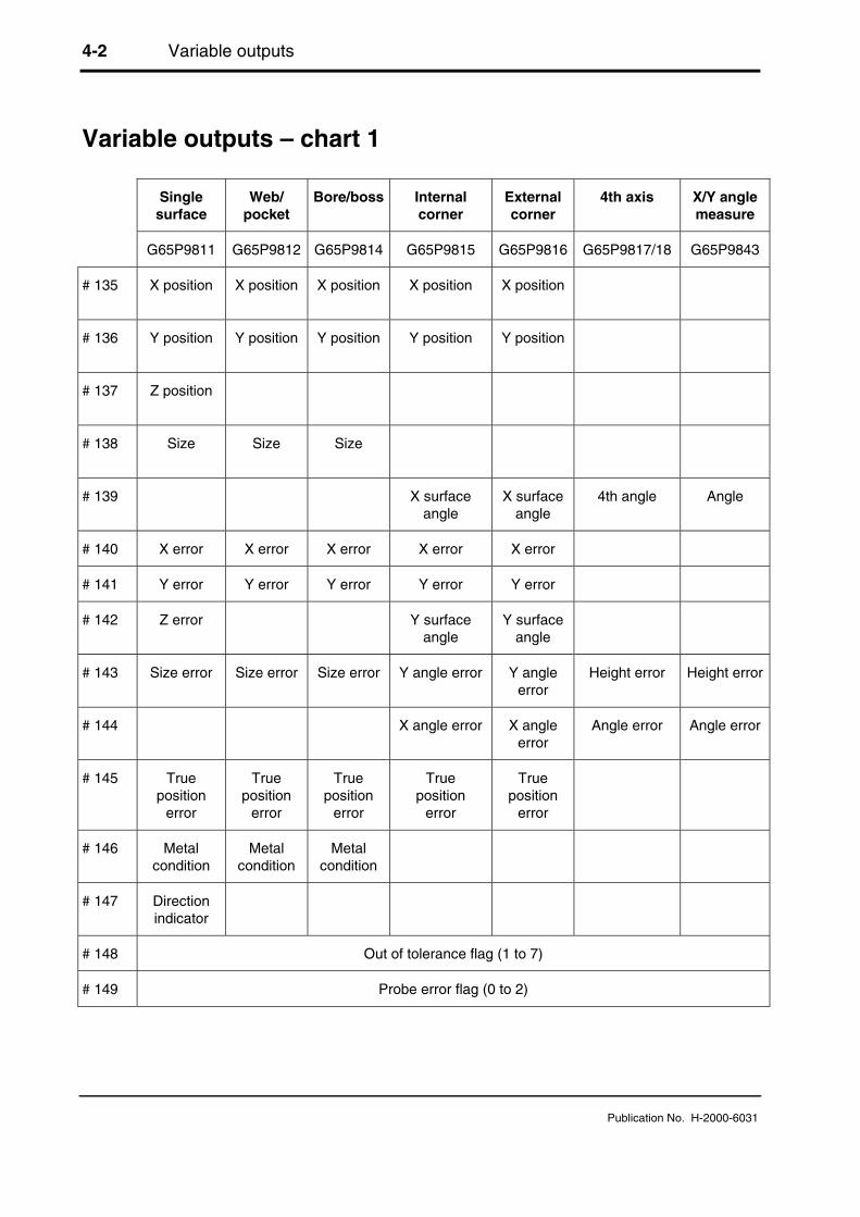
Variable outputs – chart 1
Singlesurface
Web/pocket
Bore/boss Internalcorner
Externalcorner
4th axis X/Y anglemeasure
G65P9811 G65P9812 G65P9814 G65P9815 G65P9816 G65P9817/18 G65P9843
# 135 X position X position X position X position X position
# 136 Y position Y position Y position Y position Y position
# 137 Z position
# 138 Size Size Size
# 139 X surfaceangle
X surfaceangle
4th angle Angle
# 140 X error X error X error X error X error
# 141 Y error Y error Y error Y error Y error
# 142 Z error Y surfaceangle
Y surfaceangle
# 143 Size error Size error Size error Y angle error Y angleerror
Height error Height error
# 144 X angle error X angleerror
Angle error Angle error
# 145 Trueposition
error
Trueposition
error
Trueposition
error
Trueposition
error
Trueposition
error
# 146 Metalcondition
Metalcondition
Metalcondition
# 147 Directionindicator
# 148 Out of tolerance flag (1 to 7)
# 149 Probe error flag (0 to 2)

Variable outputs 4-3
Publication No. H-2000-6031
Variable outputs – chart 2
PCDbore/boss
Stockallowance
Angled singlesurface
Angledweb/pocket
3-pointbore/boss
Feature tofeature
G65P9819 G65P9820 G65P9821 G65P9822 G65P9823 G65P9834
# 135 X position X positionfrom start
X position X position X incrementaldistance
# 136 Y position Y positionfrom start
Y position Y position Y incrementaldistance
# 137 PCD Z incrementaldistance
# 138 Size Sizefrom start
Size Size Minimumdistance
# 139 Angle Angle
# 140 X error X error X error X error X error
# 141 Y error Y error Y error Y error Y error
# 142 PCD error Z error
# 143 Size error Size error Size error Size error Minimumdistance error
# 144 Angle error Maximumvalue
Angle error
# 145 Trueposition
error
Minimumvalue
True positionerror
True positionerror
True positionerror
True positionerror
# 146 Metalcondition
Variation(stock)
Metal condition Metalcondition
Metalcondition
Metalcondition
# 147 Holenumber
Directionindicator
# 148 Out of tolerance flag (1 to 7)
# 149 Probe error flag (0 to 2)

4-4 Variable outputs
Publication No. H-2000-6031
This is page is intentionally left blank.

Protected positioning cycle 5-1
Publication No. H-2000-6031
Chapter 5
Protected positioning cycle
When the probe moves around the workpiece, it is important that the stylus is protectedagainst a collision with the workpiece. This chapter describes how to use macro O9810 toset up the protected positioning of the probe. After it is correctly set, the probe will stopmoving in the event of a collision
Contained in this chapter
Protected positioning (probe trigger monitor) (O9810) .................................................... 5-2

5-2 Protected positioning cycle
Publication No. H-2000-6031
Protected positioning (probe trigger monitor) (O9810)
Figure 5.1 Probe protected positioning
Description
It is important when moving around the workpiece to protect the probe stylus againstcollision. When this cycle is used the machine will stop in the event of a collision.
Application
Select the probe and move to a safe plane. The probe should be made active at this pointand then it can be moved to a measuring position using this macro call. In the event of acollision, the machine will stop and either a PATH OBSTRUCTED alarm will result, or anerror flag #148 will be set (see Mm input).
Format
G65 P9810 Xx Yy Zz [Ff Mm]where [ ] denotes optional inputs
Example: G65P9810 Z10. F0.8 M0.2

Protected positioning cycle 5-3
Publication No. H-2000-6031
Compulsory inputs
Xx x=Yy y= The target positions for the probe positioning move.Zz z=
Optional inputs
Ff f= The modal feedrate for all protected positioning moves. The feedrate willbe modal to this macro and subsequent feedrate calls are unnecessaryunless a change of feedrate is required. The maximum safe fast feedrateestablished during installation should not be exceeded.
Mm m=1.0 Will set a probe trigger flag (no PATH OBSTRUCTED alarm)
#148 = 0 (no probe trigger)
#148 = 7 (probe triggered)
Example
G1G54X20.Y50.
G43H20Z100. Move to a safe plane.
G65P9832 Spin the probe on (includes M19) or M19 for spindleorientation.
G65P9810Z10.F3000 Protected positioning move.
G65P9811Z0S1 Single surface measure.

5-4 Protected positioning cycle
Publication No. H-2000-6031
This page is intentionally left blank.
Calibrating the probe 6-1
Publication No. H-2000-6031
Chapter 6
Calibrating the probe
Before a probe is used, it is important that you calibrate it correctly. This chapterdescribes the four macros you should use for calibrating a probe. If you need to knowmore about calibrating a probe, you will find helpful information contained in Chapter 1,"Getting started".
Contained in this chapter
Calibration cycles – an overview...................................................................................... 6-2
Calibrating the probe length (O9801)............................................................................... 6-3
Calibrating the stylus X and Y offsets (O9802) ................................................................ 6-5
Calibrating the stylus ball radius (O9803) ........................................................................ 6-8
Calibrating the vector stylus ball radius (O9804) ........................................................... 6-11
Example 1 – Full calibration in an internal feature ......................................................... 6-14
Example 2 – Full calibration on an external feature....................................................... 6-16

6-2 Calibrating the probe
Publication No. H-2000-6031
Calibration cycles – an overview
Four calibration cycles are provided with the Inspection Plus software. These may beused in conjunction with one another for complete calibration of the probe. The purpose ofeach macro is summarised below.
Macro O9801 This is used to establish the probe length in its tool shank.
Macro O9802 This is used to establish the stylus off-centre values.
Macro O9803 This is used to establish the stylus ball radius values. It is suitable forall measuring cycles except for O9821, O9822 and O9823.
Macro O9804 This is used to establish the vector stylus ball radius values. It issuitable for all measuring cycles, including O9821, O9822 and O9823.
For complete calibration of a probe system, you must use macros O9801, O9802, andeither O9803 or O9804. Examples of full calibration procedures are described in thesections "Example 1 – Full calibration in an internal feature" and "Example 2 – Fullcalibration on an external feature" at the end of this chapter.
The Renishaw calibration cycles are split into separate cycles for flexibility. If, however,the calibration feature is accurately known for both size and position, e.g. a ring gaugewhere the size is known, and the position is accurately found using a dial test indicator, itis then possible for you to write a program which completes the full calibration procedurein one operation by calling all of the above macros.
Calibrating the probe 6-3
Publication No. H-2000-6031
Calibrating the probe length (O9801)
Tt Tool offset
Zz Ref. height
YZ
X
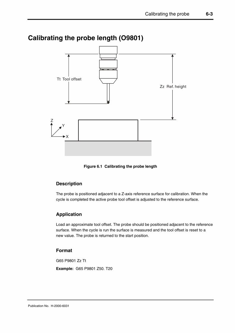
Figure 6.1 Calibrating the probe length
Description
The probe is positioned adjacent to a Z-axis reference surface for calibration. When thecycle is completed the active probe tool offset is adjusted to the reference surface.
Application
Load an approximate tool offset. The probe should be positioned adjacent to the referencesurface. When the cycle is run the surface is measured and the tool offset is reset to anew value. The probe is returned to the start position.
Format
G65 P9801 Zz Tt
Example: G65 P9801 Z50. T20
6-4 Calibrating the probe
Publication No. H-2000-6031
Compulsory inputs
Tt t= Active tool offset number.
Zz z= Reference surface position.
Outputs
The active tool offset will be set.
Example
Set X, Y, Z values in work offset G54
O 0001
G90G80G40G0 Preparatory codes for the machine.
G54X0Y0 Start position.
G43H1Z100. Activate offset 1, go to 100 mm (3.94 in).
G65P9832 Spin the probe on (includes M19) or M19 for spindleorientation.
G65P9810Z10.F3000 Protected positioning move.
G65P9801Z0T1 Datum Z direction.
G65P9810Z100. Protected positioning move.
G65P9833 Spin the probe off (when applicable).
G28Z100. Reference return.
H00 Cancel offset.
M30 End of program.
NOTE: The tool offset must be active. The active tool offset H word number must be thesame as the T input number (see above)

Calibrating the probe 6-5
Publication No. H-2000-6031
Calibrating the stylus X and Y offsets (O9802)
4
#502
Dd
Zz
Y
X3
1 2
Figure 6.2 Calibrating the stylus X and Y offsets
Description
The probe is positioned inside a pre-machined hole at a suitable height for calibration.When this cycle is completed the stylus offset amounts in the X and Y axes are stored.
Application
Pre-machine a hole with a suitable boring bar, so that the exact centre of the hole isknown. Position the probe to be calibrated inside the hole, and the spindle on the knowncentre position with the spindle orientation active. When the cycle is run, four measuringmoves are made in order to determine the X offset, and Y offset of the stylus. The probeis then returned to the start position.
Format
G65 P9802 Dd [Zz]where [ ] denotes optional inputs
Example: G65 P9802 D50.005 Z50.
Compulsory input
Dd d= Nominal size of feature

6-6 Calibrating the probe
Publication No. H-2000-6031
Optional input
Zz z= The absolute Z-axis measuring position when calibrating on an externalfeature. If this is omitted a bore cycle is assumed.
Outputs
The following data will be stored:
#502 = X-axis stylus offset
#503 = Y-axis stylus offset
Example 1: Stylus X, Y offset calibration
A tool offset must be active before running this program.
Position the stylus in the bored hole at the required depth. The spindle centre must bepositioned exactly on the bored hole centre-line.
O0002
G90G80G40G0 Preparatory codes for the machine.
G65P9832 Spin the probe on (includes M19), or M19 for spindleorientation.
G65P9802D50. Calibrate in a 50 mm (1.97 in) diameter bored hole.
G65P9833 Spin the probe off (when applicable).
M30 End of program.
Example 2: Alternative stylus X, Y offset calibration
Run a complete positioning and calibration program as follows.
Set the exact X, Y, and Z feature positions in a work offset (example using G54).
O0002
G90G80G40G0 Preparatory codes for the machine.
G54X0Y0 Move to centre of the feature.
G43H1Z100. Activate offset 1, go to 100 mm (3.94 in) above.
G65P9832 Spin the probe on (includes M19), or M19 for spindleorientation.

Calibrating the probe 6-7
Publication No. H-2000-6031
G65P9810Z-5.F3000 Protected positioning move into hole.
G65P9802D50. Calibrate in a 50 mm (1.97 in) diameter bored hole.
G65P9810Z100.F3000 Protected positioning move retract to 100 mm (3.94 in).
G65P9833 Spin the probe off (when applicable).
G28Z100. Reference return.
H00 Cancel offset (when applicable).
M30 End of program

6-8 Calibrating the probe
Publication No. H-2000-6031
Calibrating the stylus ball radius (O9803)
NOTE: Do not use this cycle to calibrate the radius of the stylus ball if, subsequently, youintend using vector measuring macros O9821, O9822, or O9823. The stylus ball radiusmust be calibrated using macro O9804 instead.
4
#501
#500
Dd
Zz
Y
X3
1
5
2
6
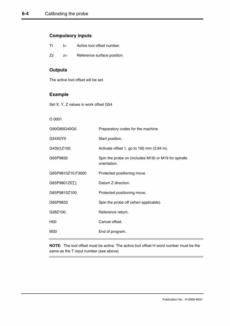
Figure 6.3 Calibrating the stylus ball radius
Description
The probe is positioned inside a calibrated ring gauge at a suitable height for calibration.When this cycle is completed the stylus ball radius values are stored.
Application
Clamp a calibrated ring gauge on the machine table at an approximately known position.Position the probe to be calibrated inside the ring gauge on the approximate centreposition, with spindle orientation active. When the cycle is run, six moves are made inorder to determine the stylus ball radius values. The probe is then returned to the startposition.
Format
G65 P9803 Dd [Zz Ss]where [ ] denote optional inputs
Example: G65 P9803 D50.005 Z50. S1.
Calibrating the probe 6-9
Publication No. H-2000-6031
Compulsory input
Dd d= Reference ring gauge size
Optional inputs
Ss s= The work offset number which will be set.The work offset number will be updated.S1 to S6 (G54 to G59)S0 (external work offset).S101 to S148 (G54.1 P1 to G54.1 P48) additional offsets option.New work offset = active work offset + error.New external offset = external offset + error.
Zz z= The absolute Z-axis measuring position when calibrating on an externalfeature. If this is omitted a ring gauge cycle is assumed.
Outputs
The following data will be stored as shown:
#500 = X+, X-, stylus ball radius (XRAD)
#501 = Y+, Y-, stylus ball radius (YRAD)
Example 1: Stylus ball radius calibration
A tool offset must be active before running this program. If your machine does not retainthe offset then use the alternative example.
Position the probe stylus approximately on-centre in the ring gauge and at the requireddepth.
O0003
G90G80G40G0 Preparatory codes for the machine.
G65P9832 Spin the probe on (includes M19) or M19 for spindleorientation.
G65P9803D50.001 Calibrate in a 50.001 mm (1.9685 in) diameter ring gauge.
G65P9833 Spin the probe off (when applicable).
M30 End of program.

6-10 Calibrating the probe
Publication No. H-2000-6031
Example 2: Alternative stylus ball radius calibration
Run a complete positioning and calibration program as follows.
Set the approximate X, Y, Z feature positions in a work offset (example using G54).
O0003
G90G80G40G00 Preparatory codes for the machine.
G54X0Y0 Move to centre of feature.
G43H1Z100. Activate offset 1, go to 100 mm (3.94 in) above.
G65P9832 Spin the probe on (includes M19), or M19 for spindleorientation.
G65P9810Z-5.F3000 Protected positioning move into hole.
G65P9803D50.001 Calibrate in a 50.001 mm (1.9685 in) ring gauge.
G65P9810Z100.F3000 Protected positioning move retract to 100 mm (3.94 in).
G65P9833 Spin the probe off (when applicable).
G28Z100. Reference return.
H00 Cancel offset (when applicable).
M30 End of program.

Calibrating the probe 6-11
Publication No. H-2000-6031
Calibrating the vector stylus ball radius (O9804)
NOTE: You must use this cycle to calibrate the radius of the stylus ball if you intend usingvector measuring macros O9821, O9822, or O9823 (described in Chapter 8, "Vectormeasuring cycles"). Do not calibrate the stylus ball radius using macro O9803.
4
#501 #500
Additional vector moves (7 to 14)at every 30
Dd
Zz
Y
X3
1
5
2
6
Figure 6.4 Calibrating the vector stylus ball radius
Description
The probe is positioned inside a calibrated ring gauge at a suitable height for calibration.When the cycle is completed the stylus ball radius values are stored. A total of 12calibration radii at 30 degree intervals are established.
Application
Clamp a calibrated ring gauge on the machine table at an approximately known position.The probe to be calibrated is positioned inside the ring gauge on the approximate centreposition, with spindle orientation active. When the cycle is run, 14 moves are made inorder to determine the stylus ball radius values. The probe is then returned to the startposition.
6-12 Calibrating the probe
Publication No. H-2000-6031
Format
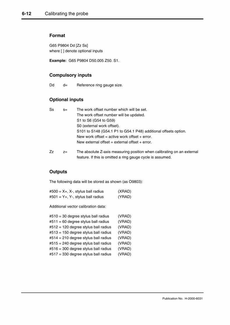
G65 P9804 Dd [Zz Ss]where [ ] denote optional inputs
Example: G65 P9804 D50.005 Z50. S1.
Compulsory inputs
Dd d= Reference ring gauge size.
Optional inputs
Ss s= The work offset number which will be set.The work offset number will be updated.S1 to S6 (G54 to G59)S0 (external work offset).S101 to S148 (G54.1 P1 to G54.1 P48) additional offsets option.New work offset = active work offset + error.New external offset = external offset + error.
Zz z= The absolute Z-axis measuring position when calibrating on an externalfeature. If this is omitted a ring gauge cycle is assumed.
Outputs
The following data will be stored as shown (as O9803):
#500 = X+, X-, stylus ball radius (XRAD)#501 = Y+, Y-, stylus ball radius (YRAD)
Additional vector calibration data:
#510 = 30 degree stylus ball radius (VRAD)#511 = 60 degree stylus ball radius (VRAD)#512 = 120 degree stylus ball radius (VRAD)#513 = 150 degree stylus ball radius (VRAD)#514 = 210 degree stylus ball radius (VRAD)#515 = 240 degree stylus ball radius (VRAD)#516 = 300 degree stylus ball radius (VRAD)#517 = 330 degree stylus ball radius (VRAD)

Calibrating the probe 6-13
Publication No. H-2000-6031
Example 1: Vector stylus ball radius calibration
A tool offset must be active before running this program. If your machine does not retainthe offset, then use the alternative example.
Position the probe approximately on-centre in the ring gauge and at the required depth.
O0004
G90G80G40G0 Preparatory codes for the machine.
G65P9832 Spin the probe on (includes M19), or M19 for spindleorientation.
G65P9804D50.001 Calibrate in a 50.001 mm (1.9685 in) diameter ring gauge.
G65P9833 Spin the probe off (when applicable).
M30 End of program.
Example 2: Alternative vector stylus ball radius calibration
Run a complete positioning and calibration program as follows.
Set the approximate X, Y, Z feature positions in a work offset (example using G54).
O0004
G90G80G40G0 Preparatory codes for the machine.
G54X0Y0 Move to centre of feature.
G43H1Z100. Activate offset 1, go to 100 mm (3.94 in) above.
G65P9832 Spin the probe on (includes M19), or M19 for spindleorientation.
G65P9810Z-5.F3000 Protected positioning move into the hole.
G65P9804D50.001 Calibrate in a 50.001 mm (1.9685 in) diameter ring gauge.
G65P9810Z100.F3000 Protected positioning move retract to 100 mm (3.94 in).
G65P9833 Spin the probe off (when applicable).
G28Z100. Reference return.
H00 Cancel offset (when applicable).
M30 End of program.

6-14 Calibrating the probe
Publication No. H-2000-6031
Example 1 – Full calibration in an internal feature
This example describes how to carry out full calibration of the probe in an internal featureusing macros O9801, O9802 and O9804, using a 50.001 mm (1.9685 in) diameter ringgauge, with a known centre position and top face height value.
The approximate probe length must be stored in the tool offset register before running thisprogram. Set the exact X, Y, and Z feature positions in a work offset (example using G54).
1
2
7
8 and 9
12
11
10
3
46
5
Figure 6.5 Full calibration in an internal feature
O0006
G90G80G40G0 Preparatory codes for the machine.
1. G54X35.Y0 Move off centre of feature for height setting.
2. G43H1Z100. Activate offset 1, go to 100 mm (3.94 in) above.
3. G65P9832 Spin the probe on (includes M19), or M19 for spindleorientation.
4. G65P9810Z30.F3000 Protected positioning move above reference surface.
5. G65P9801Z20.006T1 Calibrate the probe length. Surface at 20.006 mm(7.876 in)
6. G65P9810X0Y0 Protected positioning move to centre.
7. G65P9810Z5. Protected positioning move into hole.
8. G65P9802D50. Calibrate in a 50 mm (1.97 in) diameter bored hole toestablish the X,Y stylus offset.

Calibrating the probe 6-15
Publication No. H-2000-6031
9. G65P9804D50.001 Calibrate in a 50.001 mm (1.9685 in) diameter ringgauge to establish the ball radius values, including thevector directions.
10. G65P9810Z100.F3000 Protected positioning move retract to 100 mm(3.94 in).
11. G65P9833 Spin the probe off (when applicable).
12. G28Z100. Reference return.
H00 Cancel offset (when applicable)
M30 End of program

6-16 Calibrating the probe
Publication No. H-2000-6031
Example 2 – Full calibration on an external feature
This example describes how to carry out full calibration of the probe on an externalfeature using macros O9801, O9802 and O9804, using a 50.001 mm (1.9685 in) diameterpin gauge, with a known centre position and a Z-reference surface.
The approximate probe length must be stored in the tool offset register before running thisprogram. Set the exact X, Y pin feature positions and Z surface height in a work offset(example using G54).
1
2
3
4
5
67 and 8
10
9
11
Figure 6.6 Full calibration on an external feature
O0006
G90G80G40G0 Preparatory codes for the machine.
1. G54X135.Y100. Move to centre of feature for height setting.
2. G43H1Z100. Activate offset 1, go to 100 mm (3.94 in) above.
3. G65P9832 Spin the probe on (includes M19), or M19 for spindleorientation.
4. G65P9810Z30.F3000 Protected positioning move above reference surface.
5. G65P9801Z0.T1 Calibrate the probe length. Z surface at zero.
6. G65P9810X100.Y100. Protected positioning move to centre.
7. G65P9802D50.001Z10. Calibrate on a 50.001 mm (1.9685 in) diameter pingauge to establish the X,Y stylus offset.

Calibrating the probe 6-17
Publication No. H-2000-6031
8. G65P9804D50.001Z10. Calibrate on a 50.001 mm (1.9685 in) diameter pingauge to establish the ball radius values, including thevector directions.
9. G65P9810Z100.F3000 Protected positioning move retract to 100 mm(3.94 in).
10. G65P9833 Spin the probe off (when applicable).
11. G28Z100. Reference return.
H00 Cancel offset (when applicable)
M30 End of program

6-18 Calibrating the probe
Publication No. H-2000-6031
This page is intentionally left blank

Measuring cycles 7-1
Publication No. H-2000-6031
Chapter 7
Measuring cycles
This chapter describes how to use the non-vector measuring cycles. The probe stylus ballradius must be calibrated using either macro O9803 or O9804 (see Chapter 6,"Calibrating the probe") before using the macros described here.
Contained in this chapter
X Y Z single surface measurement (O9811).................................................................... 7-2
Web/pocket measurement (O9812)................................................................................. 7-5
Bore/boss measurement (O9814).................................................................................... 7-9
Finding an internal corner (O9815) ................................................................................ 7-13
Finding an external corner (O9816) ............................................................................... 7-17

7-2 Measuring cycles
Publication No. H-2000-6031
X Y Z single surface measurement (O9811)
X,Y
Z
Figure 7.1 Measurement of a single surface
Description
This cycle measures a surface to establish the size or position.
Application
The probe should be positioned with its tool offset active adjacent to the surface. Thecycle measures the surface and returns to the start position.
There are two possibilities as follows:
1. The surface can be treated as a size, where the tool offset is updated in conjunctionwith the Tt and the Hh input.
2. The surface can be treated as a reference surface position, for the purpose ofadjusting a work offset using the Ss and Mm inputs.
Format
G65 P9811 Xx or Yy or Zz [Ee Ff Hh Mm Qq Ss Tt Uu Vv Ww]where [ ] denotes optional inputs
Example: G65P9811X50.E0.005F0.8H0.2M.2Q10.S1.T20. U.5V.5W2.
Measuring cycles 7-3
Publication No. H-2000-6031
Compulsory inputs
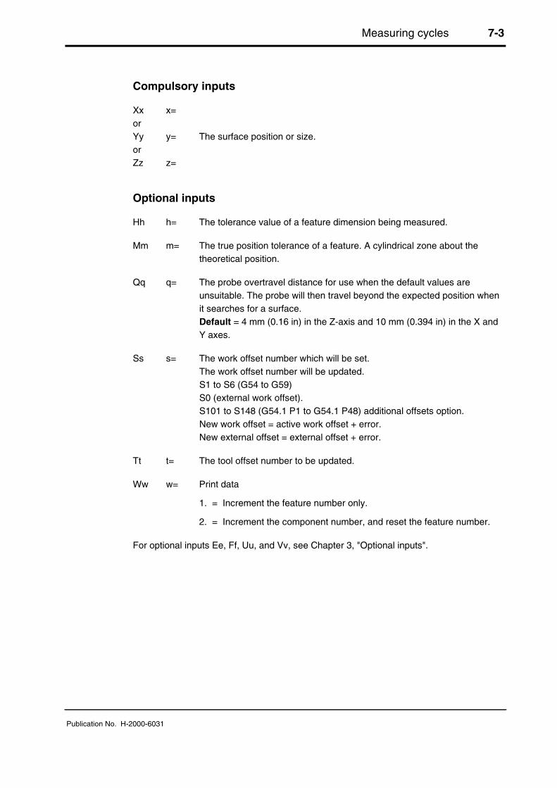
Xx x=orYy y= The surface position or size.orZz z=
Optional inputs
Hh h= The tolerance value of a feature dimension being measured.
Mm m= The true position tolerance of a feature. A cylindrical zone about thetheoretical position.
Qq q= The probe overtravel distance for use when the default values areunsuitable. The probe will then travel beyond the expected position whenit searches for a surface.Default = 4 mm (0.16 in) in the Z-axis and 10 mm (0.394 in) in the X andY axes.
Ss s= The work offset number which will be set.The work offset number will be updated.S1 to S6 (G54 to G59)S0 (external work offset).S101 to S148 (G54.1 P1 to G54.1 P48) additional offsets option.New work offset = active work offset + error.New external offset = external offset + error.
Tt t= The tool offset number to be updated.
Ww w= Print data
1. = Increment the feature number only.
2. = Increment the component number, and reset the feature number.
For optional inputs Ee, Ff, Uu, and Vv, see Chapter 3, "Optional inputs".

7-4 Measuring cycles
Publication No. H-2000-6031
Example: X and Z single surface measurement
1. T01M06 Select the probe.
2. G54X-40.Y20. Start position.
3. G43H1Z100. Activate offset 1, go to 100 mm (3.94 in).
4. G65P9832 Spin the probe on (includes M19), or M19 forspindle orientation.
5. G65P9810Z-8.F3000 Protected positioning move to start position.
6. G65P9811X-50.T10. Single surface measure.
7. G65P9810Z10. Protected positioning move.
8. G65P9810X-60. Protected positioning move.
9. G65P9811Z0T11 Single surface measure.
10. G65P9810Z100. Protected positioning move.
11. G65P9833 Spin the probe off (where applicable).
12. G28Z100. Reference return.
continue
The tool radius offset (10) is updated by the error of surface position.
1 2
12
11
10 8
6
7
4
5
3
9
Z
X
Y
Figure 7.2Probe movements
Measuring cycles 7-5
Publication No. H-2000-6031
Web/pocket measurement (O9812)
Zz
Zz
Rr
R-r
Xx, Yy
Xx, Yy
Z0
Z0
Z0
YZ
X
Xx, Yy
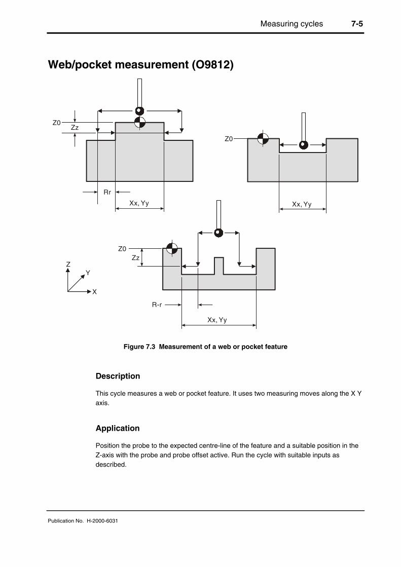
Figure 7.3 Measurement of a web or pocket feature
Description
This cycle measures a web or pocket feature. It uses two measuring moves along the X Yaxis.
Application
Position the probe to the expected centre-line of the feature and a suitable position in theZ-axis with the probe and probe offset active. Run the cycle with suitable inputs asdescribed.

7-6 Measuring cycles
Publication No. H-2000-6031
Format
G65 P9812 Xx [Ee Ff Hh Mm Qq Rr Ss Tt Uu Vv Ww]
or
G65 P9812 Yy [Ee Ff Hh Mm Qq Rr Ss Tt Uu Vv Ww]
or
G65 P9812 Xx Zz [Ee Ff Hh Mm Qq Rr Ss Tt Uu Vv Ww]
or
G65 P9812 Yy Zz [Ee Ff Hh Mm Qq Rr Ss Tt Uu Vv Ww]
where [ ] denote optional inputs.
Example: G65P9812 X50. Z100. E0.005 F0.8 H0.2 M.2 Q10. R10. S1. T20. U.5 V.5 W2.
Compulsory inputs
Xx x= Nominal size of feature when measured in the X-axis.orYy y= Nominal size of feature when measured in the Y-axis.
Zz z= The absolute Z-axis position when measuring a web feature. If this isomitted a pocket cycle is assumed.
Optional inputs
Hh h= The tolerance value of a feature dimension being measured.
Mm m= The true position tolerance of a feature. A cylindrical zone about thetheoretical position.
Qq q= The probe overtravel distance for use when the default values areunsuitable. The probe will then travel beyond the expected position whenit searches for a surface.Default = 4 mm (0.16 in) in the Z-axis, and 10 mm (0.394 in) in the X andY axes.
Rr r= An incremental dimension that is used in external features, e.g. bossesand webs, to give a radial clearance from the nominal target surface priorto a Z-axis move.Default = 5 mm (0.200 in).
R-r -r= Similar to Rr, except that the clearance is applied in the opposite directionto force an internal web cycle.Default = 5 mm (0.200 in).

Measuring cycles 7-7
Publication No. H-2000-6031
Ss s= The work offset number which will be set.The work offset number will be updated.S1 to S6 (G54 to G59)S0 (external work offset).S101 to S148 (G54.1 P1 to G54.1 P48) additional offsets option.New work offset = active work offset + error.New external offset = external offset + error.
Tt t= The tool offset number to be updated.
Ww w= Print data
1. = Increment the feature number only.
2. = Increment the component number, and reset the feature number.
For optional inputs Ee, Ff, Uu, and Vv, see Chapter 3, "Optional inputs".
Outputs
See Chapter 4, "Variable outputs".
Example 1: Measuring a web
1. T01M06 Select the probe.
2. G54X0Y0 Start position.
3. G43H1Z100. Activate offset 1, go to 100 mm (3.94 in)above.
4. G65P9832 Spin the probe on (includes M19), or M19 forspindle orientation.
5. G65P9810Z10.F3000 Protected positioning move.
6. G65P9812X50.Z-10.S2 Measure a 50.0 mm (1.968 in) wide web.
7. G65P9810Z100. Protected positioning move.
8. G65P9833 Spin the probe off (where applicable).
9. G28Z100. Reference return.
continue
The feature centre-line in the X-axis is stored in the work offset 02 (G55).
Z
1 2
3
4
6
57
8
9
X
Y
Figure 7.4Probe movements

7-8 Measuring cycles
Publication No. H-2000-6031
Example 2: Measuring a pocket (referred datum)
1. T01M06 Select the probe.
2. G54X100.Y50. Start position.
3. G43H1Z100. Activate offset 1, go to 100 mm (3.94 in).
4. G65P9832 Spin the probe on (includes M19), or M19 forspindle orientation.
5. G65P9810Z-10.F3000. Protected positioning move.
6. G65P9812X30.S2 Measure a 30.0 mm (1.181 in) wide pocket.
7. G65P9810Z100. Protected positioning move.
8. G65P9833 Spin the probe off (where applicable).
9. G28Z100. Reference return.
continue
The error of centre-line is referred to the datum point X0 and the revised X0 position is setin work offset 02 (G55).
Z
X
Y
1 2
3
4
5
6
G55
7
8
9
Figure 7.5Probe movements

Measuring cycles 7-9
Publication No. H-2000-6031
Bore/boss measurement (O9814)
Zz
Rr
R-r
Dd dia
Z0
Z0
Z0.0
YZ
X
Dd dia
Dd dia
Zz
Figure 7.6 Measurement of a bore or boss feature
Description
This cycle measures a bore or boss feature. It uses four measuring moves along the X Yaxis.
Application
Position the probe to the expected centre-line of the feature and a suitable position in theZ-axis with the probe and probe offset active. Run the cycle with suitable inputs asdescribed.

7-10 Measuring cycles
Publication No. H-2000-6031
Format
G65 P9814 Dd [Ee Ff Hh Mm Qq Rr Ss Tt Uu Vv Ww]
or
G65 P9814 Dd Zz [Ee Ff Hh Mm Qq Rr Ss Tt Uu Vv Ww]
where [ ] denotes optional inputs
Example: G65 P9814 D50.005 Z100. E0.005 F0.8 H0.2 M.2 Q10. R10. S1. T20.U.5 V.5 W2.
Compulsory inputs
Dd d= Nominal size of the feature.
Zz z= The absolute Z-axis position when measuring a boss feature. If this isomitted a bore cycle is assumed.
Optional inputs
Hh h= The tolerance value of a feature dimension being measured.
Mm m= The true position tolerance of a feature. A cylindrical zone about thetheoretical position.
Qq q= The probe overtravel distance for use when the default values areunsuitable. The probe will then travel beyond the expected position whenit searches for a surface.Default = 4 mm (0.16 in) in the Z-axis, and 10 mm (0.394 in) in the X andY axes.
Rr r= This is an incremental dimension that is used in external features, e.g.bosses and webs, to give a radial clearance from the nominal targetsurface prior to a Z-axis move.Default = 5 mm (0.200 in).
R-r -r= This is similar to Rr, except that the clearance is applied in the oppositedirection to force an internal boss cycle.Default = 5 mm (0.200 in).
Ss s= The work offset number which will be set.The work offset number will be updated.S1 to S6 (G54 to G59)S0 (external work offset).S101 to S148 (G54.1 P1 to G54.1 P48) additional offsets option.New work offset = active work offset + error.New external offset = external offset + error.
Measuring cycles 7-11
Publication No. H-2000-6031
Tt t= The tool offset number to be updated.
Ww w= Print data
1. = Increment the feature number only.
2. = Increment the component number, and reset the feature number.
For optional inputs Ee, Ff, Uu, and Vv, see Chapter 3, "Optional inputs".
Outputs
See Chapter 4, "Variable outputs".
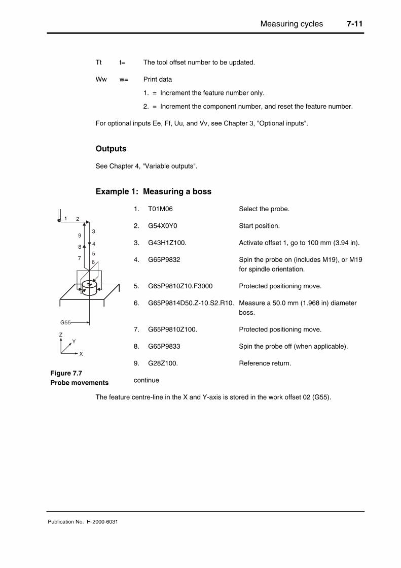
Example 1: Measuring a boss
1. T01M06 Select the probe.
2. G54X0Y0 Start position.
3. G43H1Z100. Activate offset 1, go to 100 mm (3.94 in).
4. G65P9832 Spin the probe on (includes M19), or M19for spindle orientation.
5. G65P9810Z10.F3000 Protected positioning move.
6. G65P9814D50.Z-10.S2.R10. Measure a 50.0 mm (1.968 in) diameterboss.
7. G65P9810Z100. Protected positioning move.
8. G65P9833 Spin the probe off (when applicable).
9. G28Z100. Reference return.
continue
The feature centre-line in the X and Y-axis is stored in the work offset 02 (G55).
1 2
3
4
G55
5
67
8
9
Z
X
Y
Figure 7.7Probe movements

7-12 Measuring cycles
Publication No. H-2000-6031
Example 2: Measuring a bore (referred datum)
1. T01M06 Select the probe.
2. G54X100.0Y100. Start position.
3. G43H1Z100. Activate offset 1, go to 100 mm (3.94 in).
4. G65P9832 Spin the probe on (includes M19), or M19for spindle orientation.
5. G65P9810Z-10.F3000 Protected positioning move.
6. G65P9814D30.S2 Measure a 30.0 mm (1.181 in) diameterbore.
7. G65P9810Z100. Protected positioning move.
8. G65P9833 Spin the probe off (when applicable)
9. G28Z100. Reference return
continue
The error of centre-line is referred to the datum point X0, Y0 and the revised X0, Y0position is set in work offset 02 (G55).
1 2
4
3
5
6
7
8
9
Z
G55
X
Y
Figure 7.8Probe movements

Measuring cycles 7-13
Publication No. H-2000-6031
Finding an internal corner (O9815)
Xx
Yy
Yy
Ii
Jj
Y
X
Figure 7.9 Finding an internal corner position
Description
This cycle is used to establish the corner position of a feature.
NOTE: A true corner intersection can be found, even if the corner is not 90 degrees
Application
The probe must be positioned with its tool offset active at a start position as shown in thefigure above. The probe measures the Y-axis surface first and then measures the X-axissurface. The probe then returns to the start position.
Errors occurring during the cycle return the probe to the start position.
NOTE: If the I and J inputs are missing, only two gauging moves occur. The cornerfeature is assumed to be parallel to the axes.
If either I or J is missing, then three gauging moves occur and the corner feature isassumed to be 90 degrees.
7-14 Measuring cycles
Publication No. H-2000-6031
Format
G65 P9815 Xx Yy [Bb Ii Jj Mm Qq Ss Uu Ww]
where [ ] denote optional inputs
Example: G65 P9815 X100. Y100. B2. I10. J10. M.2 Q10. S1. U.5 W2.
NOTE: If inputs I and J are used, they must be stated in this order.
Compulsory inputs
Xx x= Nominal corner position X-axis.
Yy y= Nominal corner position Y-axis.
Optional inputs
Bb b= Angle tolerance.
This applies to both X and Y surfaces. It is equal to half the totaltolerance, e.g. ±0.25 degrees = B.25 tolerance.
Ii i= Incremental distance to the second probe position along the X-axis(positive value is assumed).Default = no move.
Jj j= Incremental distance to the second probe position along the Y-axis(positive value is assumed).Default = no move.
Mm m= The true position tolerance of a feature. A cylindrical zone about thetheoretical position.
Qq q= The probe overtravel distance for use when the default values areunsuitable. The probe will then travel beyond the expected position whenit searches for a surface.Default = 4 mm (0.16 in) in the Z-axis, and 10 mm (0.394 in) in the X andY axes.
Ss s= The work offset number which will be set.The work offset number will be updated.S1 to S6 (G54 to G59)S0 (external work offset).S101 to S148 (G54.1 P1 to G54.1 P48) additional offsets option.New work offset = active work offset + error.New external offset = external offset + error.

Measuring cycles 7-15
Publication No. H-2000-6031
Ww w= Print data
1. = Increment the feature number only.
2. = Increment the component number, and reset the feature number.
For optional input Uu, see Chapter 3, "Optional inputs".
Outputs
The feature measurements will be stored in variables #135 to #149 (see variable chart).
W2. Component number +1, feature number 1
W1 Feature number +1
The following will be output:
1. Corner positions2. Tolerance if used3. Error in the X-axis4. Error in the Y-axis5. Work offset number if used
Ss The work offset stated will be set such that the nominal X Y positions will becorrected.
Mm) See Appendix H, "Output flow", for the general output structure.Uu )
NOTE: #139 is the angle of the X surface and is measured from the X+ axisdirection.#142 is the angle of the Y surface and is also measured from the X+ axis direction.

7-16 Measuring cycles
Publication No. H-2000-6031
Example: Finding an internal corner
NOTE: Co-ordinate rotation. It is possible to implement rotation using G68/G69 when thecontrol option is available.
1. T01M06 Select the probe.
2. G54X10.0Y10. Start position.
3. G43H1Z100. Activate offset 1, go to 100 mm(3.94 in).
4. G65P9832 Spin the probe on (includes M19), orM19 for spindle orientation.
5. G65P9810Z-5.F3000 Protected positioning move.
6. G65P9815X20.Y20.I10.J10. Corner find.
7. G65P9810Z100. Protected positioning move.
8. G65P9833 Spin the probe off (where applicable)
9. G28Z100. Reference return.
10. G17 Select plane.
11. G68X#135Y#136R#139 Set rotational position and angle.
continue machining
12. G69 Cancel rotation mode.
Z
X
Y
4
1
9
11
2
8
3
7
6
5
Figure 7.10Probe movements
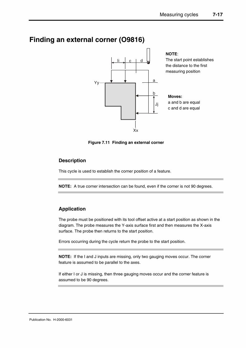
Measuring cycles 7-17
Publication No. H-2000-6031
Finding an external corner (O9816)
Yy
Xx
Jj
Ii
a
b
c d
Figure 7.11 Finding an external corner
Description
This cycle is used to establish the corner position of a feature.
NOTE: A true corner intersection can be found, even if the corner is not 90 degrees.
Application
The probe must be positioned with its tool offset active at a start position as shown in thediagram. The probe measures the Y-axis surface first and then measures the X-axissurface. The probe then returns to the start position.
Errors occurring during the cycle return the probe to the start position.
NOTE: If the I and J inputs are missing, only two gauging moves occur. The cornerfeature is assumed to be parallel to the axes.
If either I or J is missing, then three gauging moves occur and the corner feature isassumed to be 90 degrees.
NOTE:The start point establishesthe distance to the firstmeasuring position
Moves:a and b are equalc and d are equal

7-18 Measuring cycles
Publication No. H-2000-6031
Format
G65 P9816 Xx Yy [Bb Ii Jj Mm Qq Ss Uu Ww]
where [ ] denote optional inputs
Example: G65 P9816 X100. Y100. B2. I10. J10. M.2 Q10. S1. U.5 W2.
NOTE: If inputs I and J are used, they must be stated in this order.
Compulsory inputs
Xx x= Nominal corner position X-axis.
Yy y= Nominal corner position Y-axis.
Optional inputs
Bb b= Angle tolerance.This applies to both X and Y surfaces. It is equal to half the totaltolerance, e.g. ±0.25 degrees = B.25 tolerance.
Ii i= Incremental distance to the second probe position along the X-axis (apositive value is assumed).Default = no move.
Jj j= Incremental distance to the second probe position along the Y-axis (apositive value is assumed).Default = no move.
Mm m= The true position tolerance of a feature. A cylindrical zone about thetheoretical position.
Qq q= The probe overtravel distance for use when the default values areunsuitable. The probe will then travel beyond the expected position whenit searches for a surface.Default = 4 mm (0.16 in) in the Z-axis, and 10 mm (0.394 in) in the X andY axes.
Ss s= The work offset number which will be set.The work offset number will be updated.S1 to S6 (G54 to G59)S0 (external work offset).S101 to S148 (G54.1 P1 to G54.1 P48) additional offsets option.New work offset = active work offset + error.New external offset = external offset + error.
Measuring cycles 7-19
Publication No. H-2000-6031
Ww w= Print data
1. = Increment the feature number only.
2. = Increment the component number, and reset the feature number.
For optional inputs Uu, see Chapter 3, "Optional inputs".
Outputs
The feature measurements will be stored in variables #135 to #149 (see Chapter 4,"Variable outputs").
W2. Component number + 1, feature number set to 1.
W1. Feature number +1
The following will be output:
1. Corner positions2. Tolerance if used3. Error in the X-axis4. Error in the Y-axis5. Work offset number if used
Ss The work offset stated will be set such that the nominal X Y positions will becorrected.
Mm) See Appendix H, "Output flow" for the general output structure.Uu )
NOTE: #139 is the angle of the X surface and is measured from the X+ axis direction.#142 is the angle of the Y surface and is also measured from the X+ axis direction.

7-20 Measuring cycles
Publication No. H-2000-6031
Example: Finding an external corner
NOTE: Co-ordinate rotation. It is possible to implement rotation using G68/G69 when thecontrol option is available.
1. T01M06 Select the probe.
2. G54X-10.Y-10. Start position.
3. G43H1Z100. Activate offset 1, go to 100 mm (3.94 in).
4. G65P9832 Spin the probe on (includes M19), or M19 forspindle orientation.
5. G65P9810Z-5.F3000 Protected positioning move.
6. G65P9816X0Y0I10.J10. Corner find.
7. G65P9810Z100. Protected positioning move.
8. G65P9833 Spin the probe off (where applicable).
9. G28Z100. Reference return.
10. G17 Select plane.
11. G68X#135Y#136R#139 Set corner position and angle.
continue machining
12. G69 Cancel co-ordinate rotation mode.
Z
X
Y
4
1
9
11
2
8
3
7
6
5
Figure 7.12Probe movements

Vector measuring cycles 8-1
Publication No. H-2000-6031
Chapter 8
Vector measuring cycles
This chapter describes how to use the vector measuring cycles. The probe stylus ballradius must be calibrated using macro O9804 (see Chapter 6, "Calibrating the probe")before using the macros described here. Do not use macro O9803 to calibrate the probestylus.
Contained in this chapter
Angled single surface measurement (O9821) ................................................................. 8-2
Angled web or pocket measurement (O9822) ................................................................. 8-5
3-point bore or boss measurement (O9823).................................................................... 8-9

8-2 Vector measuring cycles
Publication No. H-2000-6031
Angled single surface measurement (O9821)
NOTE: The probe must have recently been calibrated using the vector stylus ball radiuscycle (O9804) (described in Chapter 6, "Calibrating the probe") before using this cycle. Donot use macro O9803 to calibrate the probe.
Dd
Aa
180°
Y
X 0°
-90°
90°
Figure 8.1 Measuring an angled surface
Description
This cycle measures a surface feature using one vectored measuring move along the X Yaxis.
Application
Position the probe to the expected reference point of the feature and a suitable position inthe Z-axis with the probe and probe offset active. Run the cycle with suitable inputs asdescribed.
Format
G65 P9821 Aa Dd [Ee Ff Hh Mm Qq Ss Tt Uu Vv Ww]where [ ] denotes optional inputs
Example: G65 P9821 A45.005 D50.005 E0.005 F0.8 H0.2 M0.2 Q10. S1.T20. U.5 V.5 W2.
NOTE:Angles in the range ±180 degrees+Aa angles (counter-clockwise)

Vector measuring cycles 8-3
Publication No. H-2000-6031
Compulsory inputs
Aa a= Direction of probe measurement measured from the X+ axis direction.
Dd d= Nominal distance to the surface (radial).
Optional inputs
Hh h= The tolerance value of a feature dimension being measured.
Mm m= The true position tolerance of a feature. A cylindrical zone about thetheoretical position.
Qq q= The probe overtravel distance for use when the default values areunsuitable. The probe then travels beyond the expected position when itsearches for a surface.Default = 4 mm (0.16 in) in the Z-axis, and 10 mm (0.4 in) in the X and Yaxes.
Ss s= The work offset number which will be set.The work offset number will be updated.S1 to S6 (G54 to G59)S0 (external work offset).S101 to S148 (G54.1 P1 to G54.1 P48) additional offsets option.New work offset = active work offset + error.New external offset = external offset + error.
Tt t= The tool offset number to be updated
Ww w= Print data
1. = Increment the feature number only.
2. = Increment the component number, and reset the feature number.
For optional inputs Ee, Ff, Uu, and Vv, see Chapter 3, "Optional inputs".
Outputs
See Chapter 4, "Variable outputs".

8-4 Vector measuring cycles
Publication No. H-2000-6031
Example: Angled single surface measurement
50.0
Y
X
45°
Figure 8.2 Measuring a single angled surface
1. T01M06 Select the probe.
2. G54X-40.Y20. Start position.
3. G43H1Z100. Activate offset 1, go to 100 mm (3.94 in).
4. G65P9832 Spin the probe on (includes M19), or M19for spindle orientation.
5. G65P9810Z-8.F3000 Protected positioning move to startposition.
6. G65P9821A45.D50.T10 Single surface measure.
7. G65P9810Z100. Protected positioning move.
8. G65P9833 Spin the probe off (when applicable).
9. G28Z100. Reference return.
The tool radius offset (10) is updated by the error of surface position.
Z
X
Y
4
1
9
2
8
3
75
6
Figure 8.3Probe movements
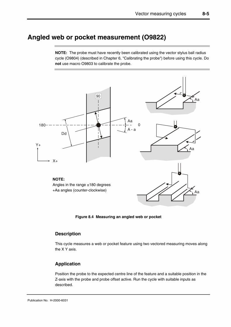
Vector measuring cycles 8-5
Publication No. H-2000-6031
Angled web or pocket measurement (O9822)
NOTE: The probe must have recently been calibrated using the vector stylus ball radiuscycle (O9804) (described in Chapter 6, "Calibrating the probe") before using this cycle. Donot use macro O9803 to calibrate the probe.
Aa
Aa
Aa
Aa
DdA - a
0180
X+
Y+
Figure 8.4 Measuring an angled web or pocket
Description
This cycle measures a web or pocket feature using two vectored measuring moves alongthe X Y axis.
Application
Position the probe to the expected centre line of the feature and a suitable position in theZ-axis with the probe and probe offset active. Run the cycle with suitable inputs asdescribed.
NOTE:Angles in the range ±180 degrees+Aa angles (counter-clockwise)

8-6 Vector measuring cycles
Publication No. H-2000-6031
Format
G65 P9822 Aa Dd [Ee Ff Hh Mm Qq Rr Ss Tt Uu Vv Ww]
or
G65 P9822 Aa Dd Zz [Ee Ff Hh Mm Qq Rr Ss Tt Uu Vv Ww]
where [ ] denotes optional inputs
Example: G65 P9822 A45.005 D50.005 Z50. E0.005 F0.8 H0.2 M0.2 Q10. R10. S1.T20. U.5 V.5 W2.
Compulsory inputs
Aa a= Angle of the surface to be measured from the X+ axis direction.
Dd d= Nominal size of the feature.
Zz z= The absolute Z axis position when measuring a web feature. If this isomitted a pocket cycle is assumed.
Optional inputs
Hh h= The tolerance value of a feature dimension being measured.
Mm m= The true position tolerance of a feature. A cylindrical zone about thetheoretical position.
Qq q= The probe overtravel distance for use when the default values areunsuitable. The probe then travels beyond the expected position when itsearches for a surface.Default = 4 mm (0.16 in) in the Z-axis, and 10 mm (0.394 in) in the X andY axes.
Rr r= This is an incremental dimension that is used in external features, e.g.bosses and webs, to give a radial clearance from the nominal targetsurface prior to a Z-axis move.Default = 5 mm (0.200 in).
R-r -r= This is similar to Rr, except that the clearance is applied in the oppositedirection to force an internal web cycle.Default = 5 mm (0.200 in).

Vector measuring cycles 8-7
Publication No. H-2000-6031
Ss s= The work offset number which will be set.The work offset number will be updated.S1 to S6 (G54 to G59)S0 (external work offset).S101 to S148 (G54.1 P1 to G54.1 P48) additional offsets option.New work offset = active work offset + error.New external offset = external offset + error.
Tt t= The tool offset number to be updated
Ww w= Print data
1. = Increment the feature number only.
2. = Increment the component number, and reset the feature number.
For optional inputs Ee, Ff, Uu, and Vv, see Chapter 3, "Optional inputs".
Outputs
See Chapter 4, "Variable outputs".

8-8 Vector measuring cycles
Publication No. H-2000-6031
Example: Angled web measurement
30°
-10
50.0
Figure 8.5 Measuring an angled web
1. T01M06 Select the probe.
2. G54X0Y0 Start position.
3. G43H1Z100.0 Activate offset 1, go to 100 mm (3.94 in).
4. G65 P9832 Spin the probe on (includes M19), or M19for spindle orientation.
5. G65P9810Z10.F3000 Protected positioning move.
6. G65P9822A30.D50.Z-10.S2 Measure a 50.0 mm (1.9685 in) wide webat 30 degrees.
7. G65P9810Z100. Protected positioning move.
8. G65P9833 Spin the probe off (when applicable).
9. G28Z100. Reference return
continue
The feature centre line in the X-axis is stored in the work offset S02 (G55).
Z
12
34
6
5
7
8
9
X
Y
Figure 8.6Probe movements

Vector measuring cycles 8-9
Publication No. H-2000-6031
3-point bore or boss measurement (O9823)
NOTE: The probe must have recently been calibrated using the vector stylus ball radiusmacro (O9804) (described in Chapter 6, "Calibration cycles") before using this cycle. Donot use macro O9803 to calibrate the probe.
180° 0°
90°
-90°
Dd
Cc
Aa
Bb
Rr
R-r
Figure 8.7 3-point bore or boss measurement
Description
This cycle measures a bore or boss feature using three vectored measuring moves alongthe X Y axis.
Application
Position the probe to the expected centre line of the feature and a suitable position in theZ-axis with the probe and probe offset active. Run the cycle with suitable inputs asdescribed.
NOTE:Angles in the range ±180 degrees+Aa angles (counter-clockwise)
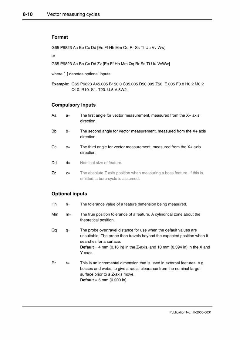
8-10 Vector measuring cycles
Publication No. H-2000-6031
Format
G65 P9823 Aa Bb Cc Dd [Ee Ff Hh Mm Qq Rr Ss Tt Uu Vv Ww]
or
G65 P9823 Aa Bb Cc Dd Zz [Ee Ff Hh Mm Qq Rr Ss Tt Uu VvWw]
where [ ] denotes optional inputs
Example: G65 P9823 A45.005 B150.0 C35.005 D50.005 Z50. E.005 F0.8 H0.2 M0.2Q10. R10. S1. T20. U.5 V.5W2.
Compulsory inputs
Aa a= The first angle for vector measurement, measured from the X+ axisdirection.
Bb b= The second angle for vector measurement, measured from the X+ axisdirection.
Cc c= The third angle for vector measurement, measured from the X+ axisdirection.
Dd d= Nominal size of feature.
Zz z= The absolute Z axis position when measuring a boss feature. If this isomitted, a bore cycle is assumed.
Optional inputs
Hh h= The tolerance value of a feature dimension being measured.
Mm m= The true position tolerance of a feature. A cylindrical zone about thetheoretical position.
Qq q= The probe overtravel distance for use when the default values areunsuitable. The probe then travels beyond the expected position when itsearches for a surface.Default = 4 mm (0.16 in) in the Z-axis, and 10 mm (0.394 in) in the X andY axes.
Rr r= This is an incremental dimension that is used in external features, e.g.bosses and webs, to give a radial clearance from the nominal targetsurface prior to a Z-axis move.Default = 5 mm (0.200 in).

Vector measuring cycles 8-11
Publication No. H-2000-6031
R-r -r= This is similar to Rr, except that the clearance is applied in the oppositedirection to force an internal boss cycle.Default = 5 mm (0.200 in).
Ss s= The work offset number which will be set.The work offset number will be updated.S1 to S6 (G54 to G59)S0 (external work offset).S101 to S148 (G54.1 P1 to G54.1 P48) additional offsets option.New work offset = active work offset + error.New external offset = external offset + error.
Tt t= The tool offset number to be updated.
Ww w= Print data
1. = Increment the feature number only.
2. = Increment the component number, and reset the feature number.
For optional inputs Ee, Ff, Uu, and Vv, see Chapter 3, "Optional inputs".
Outputs
See Chapter 4, "Variable outputs".

8-12 Vector measuring cycles
Publication No. H-2000-6031
Example: 3-point bore measurement (referred datum)
1. T01M06 Select the probe
2. G54X100.Y100. Start position
3. G43H1Z100. Activate offset 1 go to 100 mm(3.94 in)
4. G65 P9832 Spin the probe on (includes M19),or M19 for spindle orientation.
5. G65P9810Z-10.F3000 Protected positioning.
6. G65P9823D30.A30.B150.C-90.S2 Measure a 30.0 mm (1.181 in)diameter bore.
7. G65P9810Z100. Protected positioning move.
8. G65P9833 Spin the probe off (whenapplicable).
9. G28Z100. Reference return
continue
The error of centre line is referred to the datum point X0,Y0 and the revisedX0,Y0 position is set in work offset 02 (G55).
12
3
4
57
8
9
6
Z
X
Y
Figure 8.8Probe movements

Additional cycles 9-1
Publication No. H-2000-6031
Chapter 9
Additional cycles
The Inspection Plus software contains a number of macro cycles that cannot becategorised under the headings used in previous chapters of this manual (Chapters 5 to 8inclusive). This chapter describes how to use these cycles.
Contained in this chapter
4th axis X measurement (O9817) .................................................................................... 9-2
4th axis Y measurement (O9818) .................................................................................... 9-5
Bore/boss on PCD measurement (O9819) ...................................................................... 9-8
Stock allowance (O9820)............................................................................................... 9-11
Storing multi-stylus data (O9830) .................................................................................. 9-16
Loading multi-stylus data (O9831) ................................................................................. 9-20
Spinning the probe on (O9832)...................................................................................... 9-23
Spinning the probe off (O9833)...................................................................................... 9-24
Determining feature-to-feature data in the XY plane (O9834) ....................................... 9-25
Determining feature-to-feature data in the Z plane (O9834).......................................... 9-29
Updating the SPC tool offset (O9835) ........................................................................... 9-33
Optimising a probing cycle (O9836)............................................................................... 9-35
Angle measurement in the X or Y plane (O9843) .......................................................... 9-38

9-2 Additional cycles
Publication No. H-2000-6031
4th axis X measurement (O9817)
Z+
Zz
Xx
X0 (BO)
X+
Figure 9.1 4th axis X measurement
Description
The purpose of this macro is to find the slope of a surface between two points Z1 and Z2to allow the 4th axis to be rotated to compensate for the surface error.
Application
The 4th axis must be positioned to the expected angular position of the feature (i.e.surface normal to the Z axis). If the Ss input is used, the work offset register is adjusted bythe error amount.
NOTE: It is normally necessary on most machines to re-state the work offset and moveto the angular position after the cycle to make the new work offset active.
Format
G65 P9817 Xx Zz [Qq Bb Ss Ww]where [ ] denotes optional inputs.
Example: G65 P9817 X100. Z50. Q10. B2. S1. W2.
NOTE:Angle correction to 4th axis+ (positive) counter-clockwise– (negative) clockwise
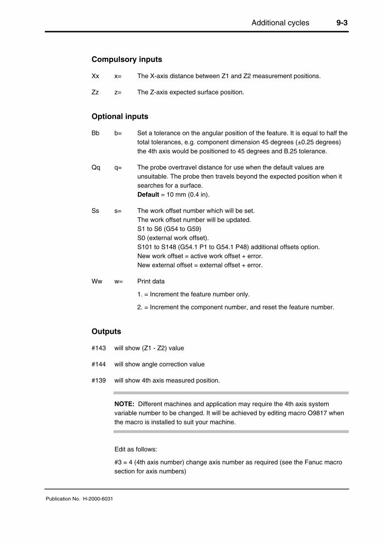
Additional cycles 9-3
Publication No. H-2000-6031
Compulsory inputs
Xx x= The X-axis distance between Z1 and Z2 measurement positions.
Zz z= The Z-axis expected surface position.
Optional inputs
Bb b= Set a tolerance on the angular position of the feature. It is equal to half thetotal tolerances, e.g. component dimension 45 degrees (±0.25 degrees)the 4th axis would be positioned to 45 degrees and B.25 tolerance.
Qq q= The probe overtravel distance for use when the default values areunsuitable. The probe then travels beyond the expected position when itsearches for a surface.Default = 10 mm (0.4 in).
Ss s= The work offset number which will be set.The work offset number will be updated.S1 to S6 (G54 to G59)S0 (external work offset).S101 to S148 (G54.1 P1 to G54.1 P48) additional offsets option.New work offset = active work offset + error.New external offset = external offset + error.
Ww w= Print data
1. = Increment the feature number only.
2. = Increment the component number, and reset the feature number.
Outputs
#143 will show (Z1 - Z2) value
#144 will show angle correction value
#139 will show 4th axis measured position.
NOTE: Different machines and application may require the 4th axis systemvariable number to be changed. It will be achieved by editing macro O9817 whenthe macro is installed to suit your machine.
Edit as follows:
#3 = 4 (4th axis number) change axis number as required (see the Fanuc macrosection for axis numbers)
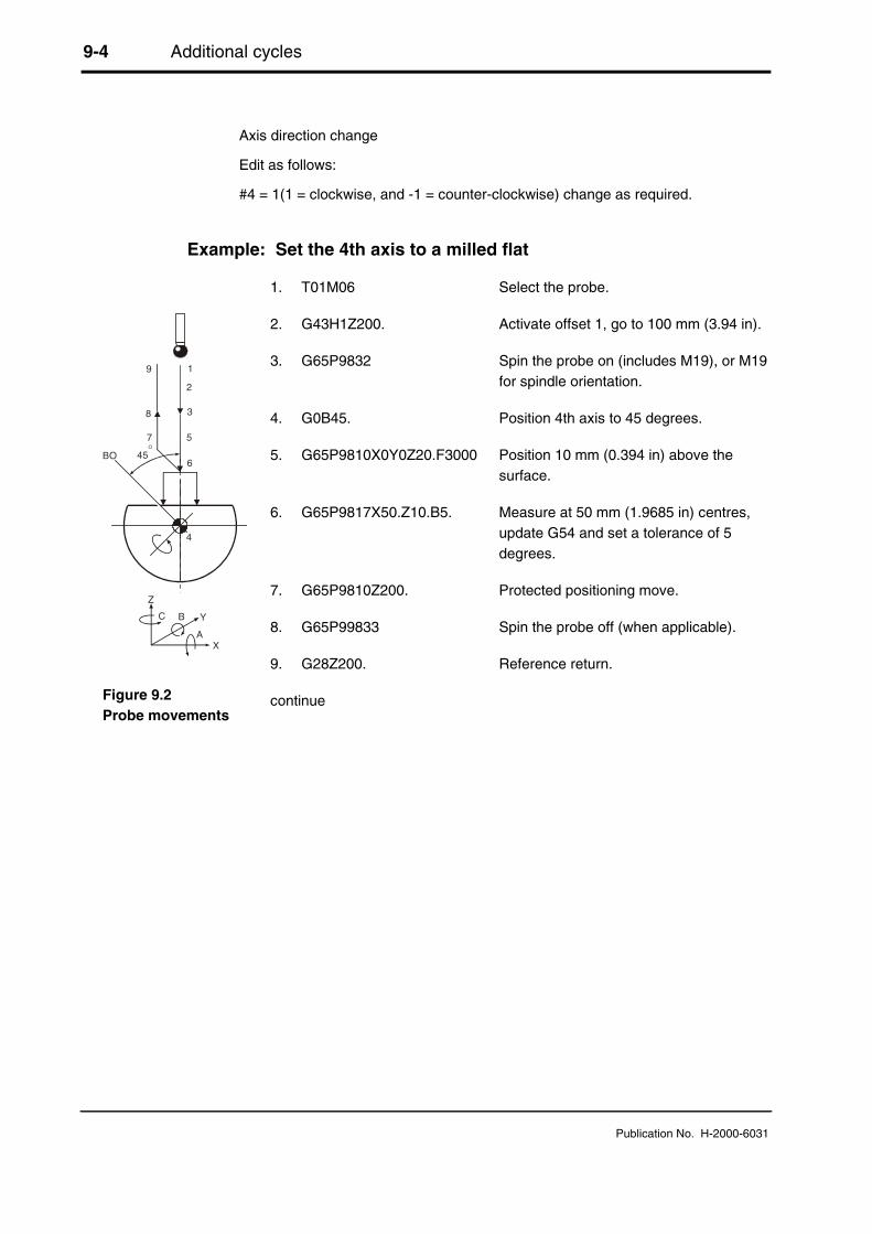
9-4 Additional cycles
Publication No. H-2000-6031
Axis direction change
Edit as follows:
#4 = 1(1 = clockwise, and -1 = counter-clockwise) change as required.
Example: Set the 4th axis to a milled flat
1. T01M06 Select the probe.
2. G43H1Z200. Activate offset 1, go to 100 mm (3.94 in).
3. G65P9832 Spin the probe on (includes M19), or M19for spindle orientation.
4. G0B45. Position 4th axis to 45 degrees.
5. G65P9810X0Y0Z20.F3000 Position 10 mm (0.394 in) above thesurface.
6. G65P9817X50.Z10.B5. Measure at 50 mm (1.9685 in) centres,update G54 and set a tolerance of 5degrees.
7. G65P9810Z200. Protected positioning move.
8. G65P99833 Spin the probe off (when applicable).
9. G28Z200. Reference return.
continue
Z
X
YB
A
C
BO
4
19
2
8 3
7
6
5
45O
Figure 9.2Probe movements

Additional cycles 9-5
Publication No. H-2000-6031
4th axis Y measurement (O9818)
Z+Zz
Yy
Y0 (BO)
Y+
Figure 9.3 4th axis Y measurement
Description
The purpose of this macro is to find the slope of a surface between two points Z1 and Z2to allow the 4th axis to be rotated to compensate for the surface error.
Application
The 4th axis must be positioned to the expected angular position of the feature (i.e.surface normal to the Z axis). If the Ss input is used, the work offset register is adjusted bythe error amount.
NOTE: It is normally necessary on most machines to re-state the work offset and move tothe angular position after the cycle to make the new work offset active.
Format
G65 P9818 Yy Zz [Qq Bb Ss Ww]where [ ] denotes optional inputs
Example: G65 P9818 Y100. Z50. Q10. B2. S1. W2.
NOTE:Angle correction to 4th axis+ (positive) counter-clockwise– (negative) clockwise

9-6 Additional cycles
Publication No. H-2000-6031
Compulsory inputs
Yy y= The Y axis distance between Z1 and Z2 measurement positions.
Zz z= The Z axis expected surface position.
Optional inputs
Bb b= Set a tolerance on the angular position of the feature. It is equal to half thetotal tolerances, e.g. component dimension 45 degrees ±.25 degrees the4th axis would be positioned to 45 degrees and B.25 tolerance.
Qq q= The probe overtravel distance for use when the default values areunsuitable. The probe then travels beyond the expected position when itsearches for a surface.Default = 10 mm (0.4 in).
Ss s= The work offset number which will be set.The work offset number will be updated.S1 to S6 (G54 to G59)S0 (external work offset).S101 to S148 (G54.1 P1 to G54.1 P48) additional offsets option.New work offset = active work offset + error.New external offset = external offset + error.
Ww w= Print data
1. = Increment the feature number only.
2. = Increment the component number, and reset the feature number.
Outputs
#143 will show (Z1 - Z2) value
#144 will show angle correction value
#139 will show 4th axis measured position
NOTE: Different machines and application may require the 4th axis systemvariable number to be changed. It is achieved by editing macro O9818 when themacro is installed to suit your machine.
Edit as follows:
#3 = 4 (4th axis number) change axis number as required (see Fanuc macrosection for axis numbers)

Additional cycles 9-7
Publication No. H-2000-6031
Axis direction change
Edit as follows:
#4 = 1 (1 = clockwise, and -1 = counter-clockwise) change as required.
Example: Set the 4th axis to a milled flat
1. T01M06 Select the probe.
2. G43H1Z200. Activate offset 1, go to 100 mm (3.94 in).
3. G65P9832 Spin the probe on (includes M19), or M19for spindle orientation.
4. G0A45. Position 4th axis to 45 degrees.
5. G65P9810X0Y0Z20.F3000 Position 10 mm (0.394 in) above thesurface.
6. G65P9818Y50.Z10.S1.B5. Measure at 50 mm (1.9685 in) centres,update G54 and set a tolerance of 5degrees.
7. G65P9810Z200. Protected positioning move.
8. G65P9833 Spin the probe off (when applicable).
9. G28Z200. Reference return.
continue
Z
Y
X
AO
4
19
2
8 3
7
6
545
O
Figure 9.4Probe movements
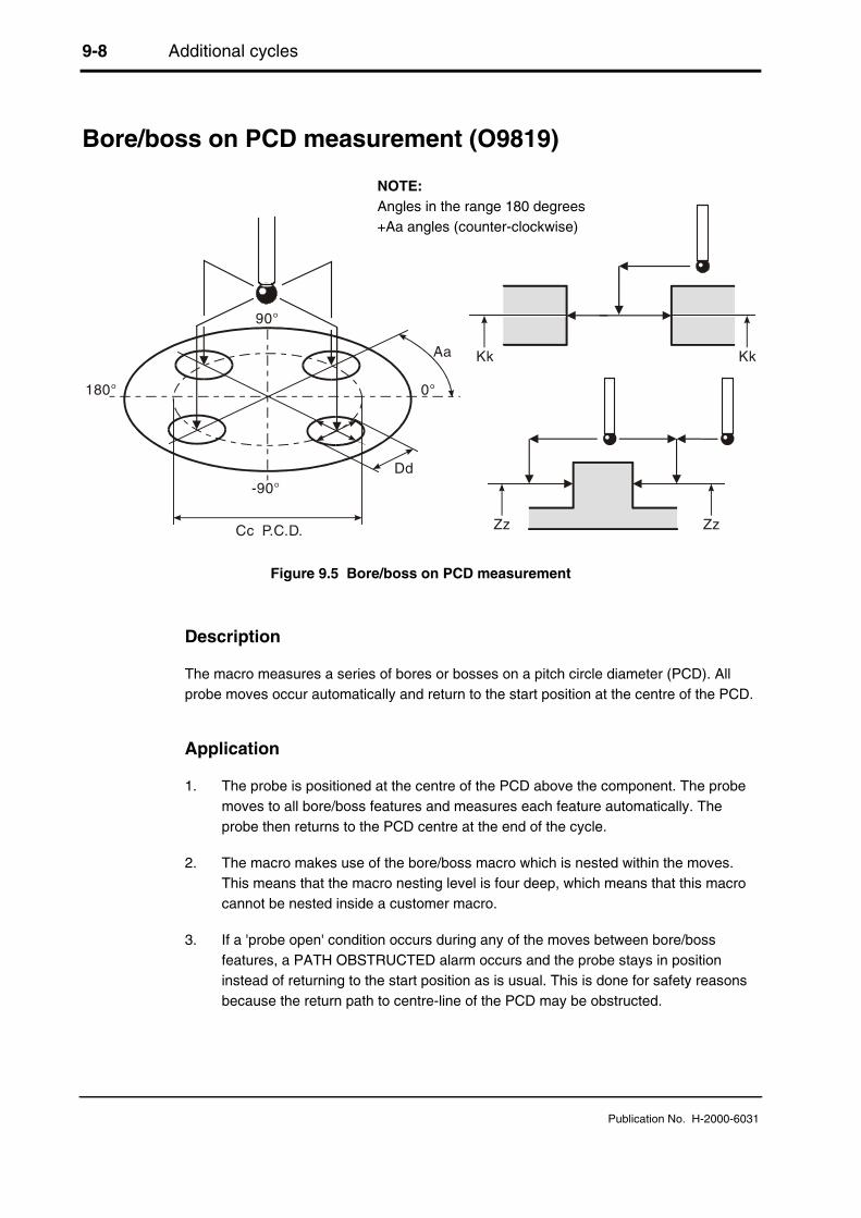
9-8 Additional cycles
Publication No. H-2000-6031
Bore/boss on PCD measurement (O9819)
Zz
KkAa
Cc P.C.D.
-90°
90°
0°
Dd
180°
Kk
Zz
Figure 9.5 Bore/boss on PCD measurement
Description
The macro measures a series of bores or bosses on a pitch circle diameter (PCD). Allprobe moves occur automatically and return to the start position at the centre of the PCD.
Application
1. The probe is positioned at the centre of the PCD above the component. The probemoves to all bore/boss features and measures each feature automatically. Theprobe then returns to the PCD centre at the end of the cycle.
2. The macro makes use of the bore/boss macro which is nested within the moves.This means that the macro nesting level is four deep, which means that this macrocannot be nested inside a customer macro.
3. If a 'probe open' condition occurs during any of the moves between bore/bossfeatures, a PATH OBSTRUCTED alarm occurs and the probe stays in positioninstead of returning to the start position as is usual. This is done for safety reasonsbecause the return path to centre-line of the PCD may be obstructed.
NOTE:Angles in the range 180 degrees+Aa angles (counter-clockwise)

Additional cycles 9-9
Publication No. H-2000-6031
Format
Boss: G65 P9819 Cc Dd Zz [Aa Bb Ee Hh Mm Qq Rr Uu Ww]
or
Bore: G65 P9819 Cc Dd Kk [Aa Bb Ee Hh Mm Qq Rr Uu Ww]
where [ ] denotes optional inputs.
Example: G65 P9819 C28.003 D50.005 K11. A45.005 B2. E0.005 H0.2 M0.2Q10. R10. U.5 W2.
Compulsory inputs
Cc c= PCD. The pitch circle diameter of the bore/boss feature.
Dd d= Diameter of the bore/boss.
Kk k= Absolute Z axis position where the bore is to be measured.
Zz z= Absolute Z axis position where the boss is to be measured.
Optional inputs
Aa a= Angle measured from the X axis to the first bore/boss feature.Default = 0.
Bb b= The number of bore/boss features on the PCD.Default = 1.
Hh h= The tolerance value of the bore/ boss dimension being measured.
Mm m= The true position tolerance of the bore or boss. A cylindrical zone aboutthe theoretical position.
Qq q= The probe overtravel distance for use when the default values areunsuitable. The probe then travels beyond the expected position when itsearches for a surface.Default = 4 mm (0.16 in) in the Z-axis, and 10 mm (0.394 in) in the X,Yaxis.
Rr r= This is an incremental dimension that is used in an external bore or bossto give a radial clearance from the nominal target surface prior to a Z-axismove.Default = 5 mm (0.200 in).
9-10 Additional cycles
Publication No. H-2000-6031
R-r -r= This is an incremental dimension that is used in an internal boss or web togive a radial clearance from the nominal target surface prior to a Z-axismove.Default = 5 mm (0.200 in).
Ww w= Print data
1. = Increment the feature number only.
2. = Increment the component number, and reset the feature number.
For optional inputs Ee and Uu, see Chapter 3, "Optional inputs".
Outputs
The feature measurements will be stored in variables #135 to #149 (see Chapter 4,"Variable outputs").
W2.0 Component number (incremented by 1). Feature number (set to 1).
W1. Feature number (incremented by 1).
The following data is output to the on-line device (printer):
• Diameter of each bore/boss
• XY absolute position, angle position and pitch circle diameter of each feature.
• Feature number.
• Error of size and position.
Refer to the print macro details for the output format.
Uu u= When the upper tolerance is exceeded, the macro continues to the endand print data is output for each feature. If #120 is set, the UPPERTOLERANCE EXCEEDED alarm occurs and #119 = 2 is set. Otherwisethe flag #119 = 2 is set only. The program continues.

Additional cycles 9-11
Publication No. H-2000-6031
Stock allowance (O9820)
P1
P1
P1
P2
P2 P2
P(6 max)
P(6 max)
P(6 max)
Z
YX
Figure 9.6 Measuring the stock allowance
Description
The cycle measures either an X or Y or Z surface at defined positions to establish themaximum and minimum stock condition of the surface.
Application
The probe should be positioned above the surface at the first measuring position. Thecycle measures the surface at this position (P1). Additional points P2 to P6 maximum aremeasured as defined, depending on the number of sets of I, J, or K inputs.
NOTES:
1. If setting a work offset, the surface position will be at the minimum measured positionand the stock value is seen in #146.
2. If NOT setting a work offset, the nominal position is assumed and the maximum andminimum values are seen in #144 and #145.

9-12 Additional cycles
Publication No. H-2000-6031
Format
X-surface measure
G65 P9820 Xx Jj Kk [Ss Uu]
or
Y-surface measure
G65 P9820 Yy Ii Kk [Ss Uu]
or
Z-surface measure
G65 P9820 Zz Ii Jj [Ss Uu]
where [ ] denotes optional inputs
Example: G65 P9820 X100. J10. K11. S1. U.5(this shows one additional [JK] pair of values, i.e. P2)
Compulsory inputs
XxorYy x, y, z = The nominal surface position for stock allowance checkorZz
I1 (P2) to i= X surface positions for P2 to P6 (maximum five additionalI5 (P6) positions).
or
J1 (P2) to j= Y surface positions for P2 to P6 (maximum five additionalJ5 (P6) positions).
or
K1 (P2) to k= Z surface positions for P2 to P6 (maximum five additionalK5 (P6) positions).
NOTE: Successive pairs of Jj, Kk valuesmust be in order for P2 to P6.
NOTE: Successive pairs of Ii, Kk valuesmust be in order for P2 to P6.
NOTE: Successive pairs of Ii, Jj valuesmust be in order for P2 to P6.

Additional cycles 9-13
Publication No. H-2000-6031
Optional inputs
Uu u= The maximum stock allowance or upper tolerance (metal condition).
1. Uu input onlyThe upper tolerance metal condition, e.g., surface at30.00 +2.0/-0.0G65P9820Z30.0U2.0IiJj
2. Uu and Ss input.The maximum stock allowance.
Ss s= The work offset number which will be set. This will be set to the minimummetal position #145.The work offset number will be updated.S1 to S6 (G54 to G59)S0 (external work offset).S101 to S148 (G54.1 P1 to G54.1P48) additional offsets option.New work offset = active work offset + error.New external offset = external offset + error.
Outputs
1. Uu input only Upper tolerance exceeded flag #148 will be set to 3
2. Uu and Ss input Excess stock flag #148 will be set to 6
#144 Maximum value (metal condition)
#145 Minimum value (metal condition)
#146 Variation (stock allowance)
Upper tolerance exceeded Excess stock
#196#195#195
Uu INPUT ONLY Uu AND Ss INPUT
#194UuUu
Nominalposition
Nominalposition
Workoffset set
to thisposition
#194
Figure 9.7 Outputs for the stock allowance cycle

9-14 Additional cycles
Publication No. H-2000-6031
Example 1 Checking a Z surface for stock variation
Y50.0X50.0
Z0
P1 at X55 Y55P2 at X155 Y55P3 at X55 Y155
P1
P2P3
Z
Figure 9.8 Checking a Z surface for stock variation
Select the probe.
G65P9810X55.Y55.Z20.F3000 Protected move to P1.
G65P9820Z0I155.J55.I55.J155.U2. Measure at P1, P2, P3 and set a 2 mm(0.0 39 in) tolerance.
continue machining
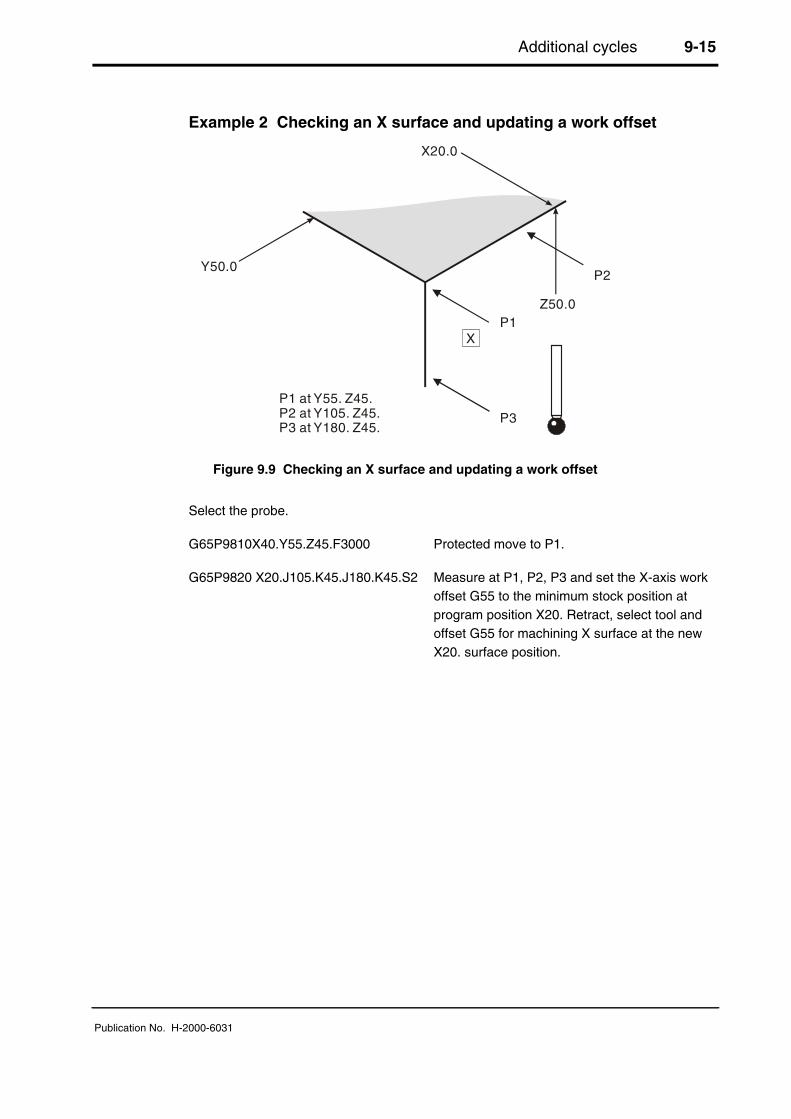
Additional cycles 9-15
Publication No. H-2000-6031
Example 2 Checking an X surface and updating a work offset
Y50.0
Z50.0
XP1
P2
P3
X20.0
P1 at Y55. Z45.P2 at Y105. Z45.P3 at Y180. Z45.
Figure 9.9 Checking an X surface and updating a work offset
Select the probe.
G65P9810X40.Y55.Z45.F3000 Protected move to P1.
G65P9820 X20.J105.K45.J180.K45.S2 Measure at P1, P2, P3 and set the X-axis workoffset G55 to the minimum stock position atprogram position X20. Retract, select tool andoffset G55 for machining X surface at the newX20. surface position.
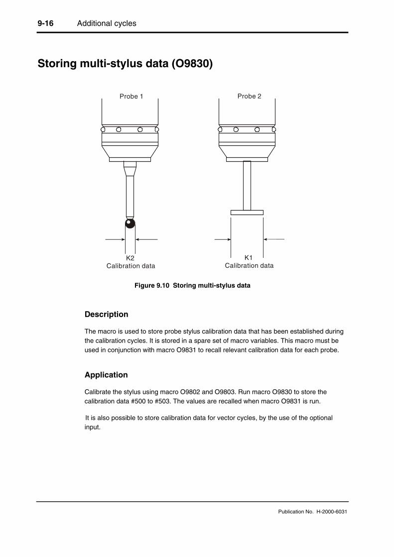
9-16 Additional cycles
Publication No. H-2000-6031
Storing multi-stylus data (O9830)
Calibration data Calibration data
Probe 1 Probe 2
K2 K1
Figure 9.10 Storing multi-stylus data
Description
The macro is used to store probe stylus calibration data that has been established duringthe calibration cycles. It is stored in a spare set of macro variables. This macro must beused in conjunction with macro O9831 to recall relevant calibration data for each probe.
Application
Calibrate the stylus using macro O9802 and O9803. Run macro O9830 to store thecalibration data #500 to #503. The values are recalled when macro O9831 is run.
It is also possible to store calibration data for vector cycles, by the use of the optionalinput.

Additional cycles 9-17
Publication No. H-2000-6031
Format
G65 P9830 Kk
Example: G65P9830K11.
Compulsory input
Kk k= The multi-stylus probe number for data storage.
Active calibration data Store location
XRAD YRAD XOFF YOFF XRAD YRAD XOFF YOFF
K1 #500 #501 #502 #503 #518 #519 #520 #521K2 #500 #501 #502 #503 #522 #523 #524 #525K3 #500 #501 #502 #503 #526 #527 #528 #529K4 #500 #501 #502 #503 #530 #531 #532 #533

9-18 Additional cycles
Publication No. H-2000-6031
For vector calibration data storage
#500 to #503 are stored as shown above, plus all the vector radii as shown below.
Buffer calibration data Store location
RAD RAD RAD RAD
K11 #510 #511 #512 #513 #534 #535 #536 #537#514 #515 #516 #517 #538 #539 #540 #541
K12 #510 #511 #512 #513 #542 #543 #544 #545#514 #515 #516 #517 #546 #547 #548 #549
When the additional macro option is installed, K13 and K14 can be used.
K13 #510 #511 #512 #513 #550 #551 #552 #553#514 #515 #516 #517 #554 #555 #556 #557
K14 #510 #511 #512 #513 #558 #559 #560 #561#514 #515 #516 #517 #562 #563 #564 #565
NOTE: Spare macro variable locations, where data can be stored, are dependent on themachine options available, and the variables that are already used by your programs.
Example: Multi-stylus store K1
O0003
G90G80G40G0 Preparatory codes for the machine.
G54X0Y0 Start position (X, Y, Z values must be set in the work offset)
G43H1Z100. Activate offset 1, go to 100 mm (3.94 in).
G65P9832 Spin the probe on (includes M19), or M19 for spindleorientation.
G65P9810Z-5.F3000 Protected positioning move for Z.
G65P9803D50.001 Calibrate in a reference feature (ring gauge).
G65P9830K1 Store calibration values for multi-stylus K1.
G65P9810Z100. Protected positioning move.
G65P9833 Spin the probe off (when applicable)
G28Z100. Reference return.

Additional cycles 9-19
Publication No. H-2000-6031
H00 Cancel offset.
M30 End of program
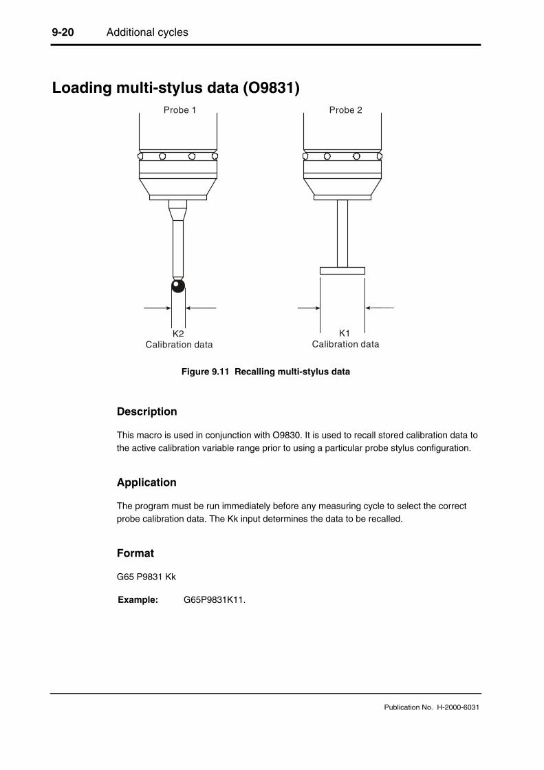
9-20 Additional cycles
Publication No. H-2000-6031
Loading multi-stylus data (O9831)
Calibration data Calibration data
Probe 1 Probe 2
K2 K1
Figure 9.11 Recalling multi-stylus data
Description
This macro is used in conjunction with O9830. It is used to recall stored calibration data tothe active calibration variable range prior to using a particular probe stylus configuration.
Application
The program must be run immediately before any measuring cycle to select the correctprobe calibration data. The Kk input determines the data to be recalled.
Format
G65 P9831 Kk
Example: G65P9831K11.
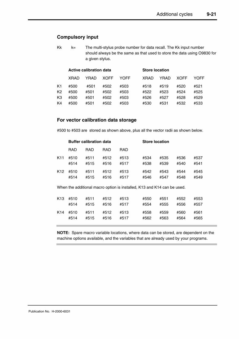
Additional cycles 9-21
Publication No. H-2000-6031
Compulsory input
Kk k= The multi-stylus probe number for data recall. The Kk input numbershould always be the same as that used to store the data using O9830 fora given stylus.
Active calibration data Store location
XRAD YRAD XOFF YOFF XRAD YRAD XOFF YOFF
K1 #500 #501 #502 #503 #518 #519 #520 #521K2 #500 #501 #502 #503 #522 #523 #524 #525K3 #500 #501 #502 #503 #526 #527 #528 #529K4 #500 #501 #502 #503 #530 #531 #532 #533
For vector calibration data storage
#500 to #503 are stored as shown above, plus all the vector radii as shown below.
Buffer calibration data Store location
RAD RAD RAD RAD
K11 #510 #511 #512 #513 #534 #535 #536 #537#514 #515 #516 #517 #538 #539 #540 #541
K12 #510 #511 #512 #513 #542 #543 #544 #545#514 #515 #516 #517 #546 #547 #548 #549
When the additional macro option is installed, K13 and K14 can be used.
K13 #510 #511 #512 #513 #550 #551 #552 #553#514 #515 #516 #517 #554 #555 #556 #557
K14 #510 #511 #512 #513 #558 #559 #560 #561#514 #515 #516 #517 #562 #563 #564 #565
NOTE: Spare macro variable locations, where data can be stored, are dependent on themachine options available, and the variables that are already used by your programs.

9-22 Additional cycles
Publication No. H-2000-6031
Example: Multi-stylus load K1 and K2
T01M06 Select the probe.
G54X100.Y100. Start position.
G43H1Z100. Activate offset 1, go to 100 mm (3.94 in).
G65P9832 Spin the probe on (includes M19), or M19 for spindleorientation.
G65P9810Z-10.F3000 Protected positioning move.
G65P9831K1 Load calibration values for multi-stylus K1.
G65P9814D30.S2 Measure a 30.0 mm (1.181 in) diameter bore.
G65P9810Z10. Protected positioning move.
G65P9810X350. Protected positioning move.
G43H2Z-10. Activate offset 2.
G65P9831K2 Load calibration values for multi-stylus K2.
G65P9814D130.S2 Measure a 130.0mm (5.12in) diameter bore.
G65P9810Z100. Protected positioning move.
G65P9833 Spin the probe off (when applicable).
G28Z100. Reference return.
continue

Additional cycles 9-23
Publication No. H-2000-6031
Spinning the probe on (O9832)
Description
This macro is used to spin the probe on prior to it being used. The probe is loaded into thespindle and moved to a safe start plane, where the above format is used to activate theprobe.
In the event of a startup failure, there is a loop in the software which tries to activate theprobe up to four times. An alarm results if the probe does not activate.
It should be noted that a small automatic Z axis movement takes place within the macro totest if the probe is active.
NOTE: The probe tool offset must be active.
Format
M98P9832
Example
G43H20Z100. Apply a tool offset and move to a safe plane.
G65P9832 Spin the probe on (includes M19), or M19 for spindleorientation.
G65P9810X- - --Y- - -F- - - Move to a gauging position.

9-24 Additional cycles
Publication No. H-2000-6031
Spinning the probe off (O9833)
Description
This macro is used to spin the probe off prior to it being used. The probe is retracted to asafe start plane, where the above format is used to switch the probe off prior to a toolchange.
There is a loop in the software, which will tries to de-activate the probe up to four times.An alarm results if the probe does not switch off.
It should be noted that a small automatic Z-axis movement takes place within the macro totest if the probe is active. This means that the G28 reference return must be donefollowing this macro, otherwise the G28 position is not effective.
NOTE: The probe tool offset must be active.
Format
M98P9833
Example:
G65P9810Z100. Retract to a safe plane with the tool offset still active.
G65P9833 Spin the probe off.
G91
G28Z0 Retract
continue

Additional cycles 9-25
Publication No. H-2000-6031
Determining feature-to-feature data in the XY plane(O9834)
P2
P1
Xx
Dd
Yy
Aa
Figure 9.12 Determining feature-to-feature data in the XY plane
Description
This is a no-movement macro that is used after two measuring cycles to determinefeature-to-feature data.
Application
Data for P1 and P2 must already be stored in variables #130 to #134 and #135 to #147 forP2, by running suitable measuring cycles.
NOTE: The order P1 and P2 is important, because the data calculated is that of P2 withrespect to P1.
Values for P1 are obtained by programming G65 P9834 without any inputs after the firstmeasuring cycle.
Values for P2 are obtained by running a second measuring cycle – the feature-to-featuredata is established by programming G65 P9834 with suitable inputs after the secondmeasuring cycle.
NOTE:Angles in the range ±180 degrees+Aa angles (counter-clockwise)

9-26 Additional cycles
Publication No. H-2000-6031
Format
G65 P9834 Xx [Ee Ff Hh Mm Ss Tt Uu Vv Ww]orG65 P9834 Yy [Ee Ff Hh Mm Ss Tt Uu Vv Ww]orG65 P9834 Xx Yy [Bb Ee Hh Mm Ss Uu Ww]orG65 P9834 Aa Dd [Bb Ee Hh Mm Ss Uu Ww]orG65 P9834 (with no inputs).
where [ ] denotes optional inputs
Examples: G65P9834X100.E0.005F0.8H0.2M0.2S1.T20.U.5V.5W2.orG65P9834Y100.E0.005F0.8H0.2M0.2S1.T20. U.5V.5W2.orG65P9834X100.Y100.B2.E0.005H0.2M0.2S1. U.5W2.orG65P9834A45.005D50.005B2.E0.005H0.2 M0.2S1.U.5W2.
NOTES: 1. Updating a tool offset with T input is only possible if either O9811 or O9821 isused for P2 data. Otherwise an alarm (T INPUT NOT ALLOWED) results.
2. This cycle cannot be used in conjunction with the web/pocket cycle macroO9812.
3. Angles. The XY plane is with respect to the X+ axis direction. Use angles inthe range ±180 degrees.
4. When G65P9834 (without any inputs) is used, then the following data isstored:
from #135 to #130#136 #131#137 #132#138 #133#139 #134

Additional cycles 9-27
Publication No. H-2000-6031
Compulsory inputs
Xx x= The nominal incremental distance in the X axis.
Yy y= The nominal incremental distance in the Y axis.
Aa a= The angle of P2 with respect to P1 measured from the X+ axis (anglesbetween ±180 degrees).
Dd d= The minimum distance between P1 and P2.
(No inputs) This is used to store output data of the last cycle for P1 data.
Optional inputs
Bb b= The angle tolerance of the surface, e.g. 30 degrees ±1 degree.
Hh h= The tolerance value of the feature dimension being measured.
Mm m= The true position tolerance of a feature. A cylindrical zone about thetheoretical position.
Ss s= The work offset number which will be set.The work offset number will be updated.S1 to S6 (G54 to G59)S0 (external work offset).S101 to S148 (G54.1 P1 to G54.1 P48) additional offsets option.New work offset = active work offset + error.New external offset = external offset + error.
Tt t= The tool offset number to be updated.
Ww w= Print data
1. = Increment the feature number only.
2. = Increment the component number, and reset the feature number.
For optional inputs Ee, Ff, Uu and Vv, see Chapter 3, "Optional inputs".

9-28 Additional cycles
Publication No. H-2000-6031
Example 1 Measuring the incremental distance between two holes
1. G65P9810X30.Y50.F3000 Protected positioning move.
2. G65P9810Z-10. Protected positioning move.
3. G65P9814D20. P1 20 mm (0.787 in) bore.
4. G65P9834 Store data.
5. G65P9810Z10. Protected positioning move.
6. G65P9810X80.Y78.867 Move to new position.
7. G65P9810Z-10. Protected positioning move.
8. G65P9814D30. P2 30 mm (1.181 in) bore.
And either this
9. G65P9834X50.Y28.867M.1 Incremental distance measure with0.1 mm (0.0039 in) true positiontolerance.
or this
9. G65P9834A30.D57.735M.1
Example 2: Surface to bore measurement
1. G65P9810X10.Y50.F3000 Protected positioning move.
2. G65P9810Z-10. Protected positioning move.
3. G65P9811X0. P1 at X0 mm (0 in) position.
4. G65P9834 Store data.
5. G65P9810Z10. Protected positioning move.
6. G65P9810X-50. Move to new position.
7. G65P9810Z-10. Protected positioning move.
8. G65P9814D20.5 P2 20.5 mm (0.807 in) bore.
9. G65P9834X-50.H.2 Measure distance -50 mm (-1.97 in)
6
7
9 and 10
4 and 5
3
21
8
Z
X
Y
Figure 9.13Probe movements
1
2
3 and 4
5
6
7
8 and 9
Z
X
Y
Figure 9.14Probe movements

Additional cycles 9-29
Publication No. H-2000-6031
Determining feature-to-feature data in the Z plane (O9834)
P2
P2
P1
P1
+Dd
-Dd
Zz
Z+
X+
Y+
Zz
+Aa
+Aa
-Zz
+Zz
Figure 9.15 Determining feature-to-feature data in the Z plane
Description
This is a no-movement macro that is used after two measuring cycles to determinefeature-to-feature data.
Application
Data for P1 and P2 must already be stored in variables #130 to #134 and #135 to #147 forP2, by running suitable measuring cycles.
NOTE: The order P1 and P2 is important, because the data calculated is that of P2 withrespect to P1.
Values for P1 are obtained by programming G65 P9834 without any inputs after the firstmeasuring cycle.
Values for P2 are obtained by running a second measuring cycle, and the feature-to-feature data is established by programming G65 P9834 with suitable inputs after thesecond measuring cycle.
NOTE:Angles in the range ±180 degrees+Aa angles (counter-clockwise)

9-30 Additional cycles
Publication No. H-2000-6031
Format
G65 P9834 Zz [Ee Ff Hh Mm Ss Tt Uu Vv Ww]orG65 P9834 Aa Zz [Bb Ww]orG65 P9834 Dd Zz [Bb Ww]orG65 P9834 (with no inputs)
where [ ] denotes optional inputs
Examples: G65P9834Z50.E0.005F0.8H0.2M0.2S1.T20. U.5V.5W2.orG65P9834A45.005Z50.B2.W2.orG65P9834D50.005Z50.B2.W2.orG65P9834 (with no inputs)
NOTES: 1. Updating a tool offset with T input is only possible if O9811 is used for P2data. Otherwise an alarm (T INPUT NOT ALLOWED) results.
2. Angles. These are with respect to the XY. Use angles in the range ±180degrees.
3. When G65P9834 (without any inputs) is used, then the following data isstored: from #135 to #130
#136 #131#137 #132#138 #133#139 #134
Inputs
Aa Zz or Dd Zz inputs
1. +Dd/-Dd values should be used to indicate the direction of P2 with respect to P1.
2. +Aa angles (counter-clockwise).
3. Angles between ±180 degrees.
Zz only input
+Zz/-Zz values should be used to indicate the direction of P2 with respect to P1.

Additional cycles 9-31
Publication No. H-2000-6031
Compulsory inputs
Aa a= The angle of P2 with respect to P1 measured from the XY plane (anglesbetween ±180 degrees).
Zz z= The nominal incremental distance in the Z axis.
or
Dd d= The minimum distance between P1 and P2 measured in the XY plane.
Zz z= The nominal incremental distance in the Z axis.
or
(No inputs) This is used to store output data of the last cycle for P1 data.
Optional inputs
Bb b= The angle tolerance of the surface, e.g. 30 degrees ±1 degree.
Hh h= The tolerance value of the feature dimension being measured.
Mm m= The true position tolerance of a feature. A cylindrical zone about thetheoretical position.
Ss s= The work offset number which will be set.The work offset number will be updated.S1 to S6 (G54 to G59)S0 (external work offset).S101 to S148 (G54.1 P1 to G54.1 P48) additional offsets option.New work offset = active work offset + error.New external offset = external offset + error.
Tt t= The tool offset number to be updated.
Ww w= Print data
1. = Increment the feature number only.
2. = Increment the component number, and reset the feature number.
For optional inputs Ee, Ff, Uu and Vv, see Chapter 3, "Optional inputs".

9-32 Additional cycles
Publication No. H-2000-6031
Example 1: Measuring the incremental distance between twosurfaces
1. G65P9810X30.Y50.F3000 Protected positioning move.
2. G65P9810Z30. Protected positioning move.
3. G65P9811Z20. P1 20 mm (0.787 in) surface.
4. G65P9834 Store data.
5. G65P9810X50. Move to new position.
6. G65P9811Z15. P2 15 mm (0.591 in) surface.
7. G65P9834Z-5.H.1 Feature to feature at -5.0 mm (-0.197 in).
Example 2: Measuring an angled surface
1. G65P9810X30.Y50.F3000 Protected positioning move.
2. G65P9810Z30. Protected positioning move.
3. G65P9811Z20. P1 at 20 mm (0.787 in) position.
4. G65P9834 Store data.
5. G65P9810X77.474 Move to new position.
6. G65P9811Z10. P2 at 10 mm (0.394 in) position.
and either this
7. G65P9834D27.474Z-10.B.5 Measure slope -20 degrees (clockwise)angle tolerance ±5 degrees.
or this
7. G65P9834A-20.Z-10.B.5
2
1
5
3 and 4
6 and 7
Z
X
Y
Figure 9.16Probe movements
2
1
5
3 and 4
6 and 7
Z
X
Y
Figure 9.17Probe movements

Additional cycles 9-33
Publication No. H-2000-6031
Updating the SPC tool offset (O9835)Cc
Vv
x
x x xx
xx
+
xNominal size
xx
Vv
Figure 9.18 Updating the SPC tool offset
Description
This macro can be used in conjunction with measuring cycles to control tool offsetupdates. It offers the possibility of providing an update based on the average value of asample of measurements.
Application
A measuring cycle should be run, but with no tool offset update (Tt input). A componenttolerance (Hh input) can be used if required. The SPC macro should follow. An averagevalue is accumulated until a specified continuous run of values are outside the controllimit. At this point the tool offset is updated, based on the average value.
IMPORTANT: Set the Mm store tool offsets to 0 on the offset page prior to use.
Format
G65P9835 Tt Mm [Vv Cc Ff Zz]where [ ] denotes optional inputs
Example: G65P9835T20.M0.2V0.25C4F0.8Z1.
Cc Run of measurements out oflimit prior to correction

9-34 Additional cycles
Publication No. H-2000-6031
Compulsory inputs
Tt t= Tool offset number for updating.
Mm m= Spare tool offset pair for storing average value and counter.
m = Accumulated average value store location.
m+1 = Counter store location.
Optional inputs
Cc c= Number of measurements out of tolerance before corrective action istakenDefault = 3.
Ff f= See Chapter 3, "Optional inputs".
Vv v= See Chapter 3, "Optional inputs".
Zz z= Flag for Z length offset update.A Z value needs to be input to force the length offset register to beupdated, otherwise the radius register will be updated.
NOTE: This input is only necessary when using type 'C' tool offset option.
Example: SPC tool offset updating
From previous
G65P9814D50.H.5 Measure bore to 0.5 mm (0.0197 in) tolerance.
G65P9835T30.M31.V.1C4. T30 = Tool offset number for updating.M31. = Spare tool offsets pair (31 and 32).V.1 = Control limit.C4. = Run of measurements out of limit.
continues

Additional cycles 9-35
Publication No. H-2000-6031
Optimising a probing cycle (O9836)
Z
(a)
(b)
(c)
#506x
Figure 9.19 Optimising a probing cycle
NOTE: For small and medium machines the default values for feedrate and back-offdistance are adequate. Therefore it is not essential to run this macro in every case.
Description
This macro is used to establish the optimum maximum feedrate and back-off distancevalues for the probing cycles.
Application
1. The probe should be made active. At this stage the spin-on macro for the opticalprobe may not be functioning. Therefore, use the MDI mode and spin the probe atS500, then stop the spindle.
2. Position the probe stylus within 2 mm (0.08 in) of the surface. Call this macro within asmall program, and run the cycle.
The probe moves towards the Z surface at 30 mm/min. (1.2 in). The cycle continues toretract and find the surface several times to establish the optimum values.
At the end, the cycle returns to the start position.
a = Start at 30 mm/min (1.181 in/min)b = #119*.6 feedratec = Maximum feedrate
9-36 Additional cycles
Publication No. H-2000-6031
NOTE: The repeat surface finding moves get progressively faster until the maximumovertravel is reached. Also, the retract position off the surface increases. It is important,therefore, that you allow for adequate Z axis movement, e.g., 60 mm (2.4 in).
The macro ends with a macro alarm message:
MESSAGE 75 (#118=BMCF DIST AND #119=FAST FEED)
These values are recommended values. They are not automatically installed into theactive variables.
Install values
1. The fast feed value in #119 must be loaded into the setting macro O9724. SeeAppendix C, "Settings macro details", for details.
2. The back-off distance in #118 must be transferred into variable #506. This is possiblein ‘manual data input mode’. The variable is to be found on the common retainedvariable page.
Format
G65 P9836 Qq
Example: G65P9836Q10.
Optional input
Qq q= The maximum overtravel for the probe.Default = 4 mm (0.16 in).
Diagnostic alarms
See Chapter 10, "Macro alarms", for details.
NOTE: Feedrates. All the feedrates within the software are related, and are dependent onthe fast feedrate #119 value, with the exception of the gauging move. This is always at30 mm/min (1.2 in/min). It should also be noted that the back-off distance #506 can beaffected by changing the feedrate #119. Running this macro will establish compatiblesetting data.

Additional cycles 9-37
Publication No. H-2000-6031
Feedrates
Feedrates are internally calculated as shown:
Basic move macro O9726
Z axis fast approach #119*.6 (3000 mm/min [120 in/min.] standard).
XY axis fast approach #119*.6 (3000 mm/min [120 in/min.] standard).
Gauge move 30 mm/min. (1.2 in/min) all axes.
All other feedrates
Z axis positioning #119*.6 (3000 mm/min. [120 in/min.] standard).
XY axis positioning #119 (5000 mm/min. [200 in/min.] standard).
Example
Write a small program to run this macro.
Position the probe at approx. 2 mm (0.08 in) above a surface, with the probe active.
%
O5036
G40G80G90 Preparatory codes for the machine.
H00 Make tool offset zero
G65P9836Q6.0 Optimise for 6 mm (0.24 in) overtravel
M30
%

9-38 Additional cycles
Publication No. H-2000-6031
Angle measurement in the X or Y plane (O9843)
X+ (AO)
Y+
Xx
Dd
Dd
Aa
X+
Yy
Figure 9.20 Measuring an angled surface in the X or Y plane
Description
This cycle measures an X axis or Y axis surface at two positions to establish the angularposition of the surface.
Application
The probe stylus must be positioned adjacent to the surface and at the required Z axisposition to provide a suitable start position. The cycle makes two measurements,symmetrically about the start position, to establish the surface angle.
Format
G65 P9843 Xx Dd [Aa Bb Qq Ww]orG65 P9843 Yy Dd [Aa Bb Qq Ww]
where [ ] denotes optional inputs
Example: G65P9843 X50.D30.A45.H.2Q15.W1.
NOTE:Aa positive angles (counter-clockwise)
Additional cycles 9-39
Publication No. H-2000-6031
Compulsory inputs
Dd d= The distance moved parallel to the X axis or Y axis between the twomeasuring positions.
Xx x= The mid-point surface position of the surface. An Xx input results in acycle measuring in the X axis direction.
Yy y= The mid-point surface position of the surface. A Yy input results in a cyclemeasuring in the Y axis direction.
NOTE: Do not mix the Xx and Yy inputs.
Optional inputs
Aa a= The nominal angle of the surface measured from the X+ axis directionpositive angles (counter-clockwise). Specify angles between ±90 degreesof the default value.Defaults: X axis measuring 90 degrees.
Y axis measuring 0 degrees.
Bb b= The angle tolerance of the surface, e.g., 30 degrees ±1 degrees. InputsA30.B1.
Qq q= The probe move overtravel distance. Default value is 10 mm (0.394 in).
Ww w= Print data
1. = Increment the feature number only.
2. = Increment the component number, and reset the feature number.
Outputs
#139 The surface angle measured from the X+ direction.
#143 The measured height difference.
#144 The surface angle error.
Alarms
Refer to Chapter 10, "Macro alarm list", for details of the macro alarms.
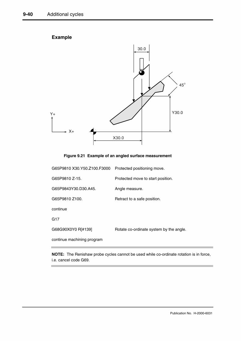
9-40 Additional cycles
Publication No. H-2000-6031
Example
Y+
X+
30.0
45O
Y30.0
X30.0
Figure 9.21 Example of an angled surface measurement
G65P9810 X30.Y50.Z100.F3000 Protected positioning move.
G65P9810 Z-15. Protected move to start position.
G65P9843Y30.D30.A45. Angle measure.
G65P9810 Z100. Retract to a safe position.
continue
G17
G68G90X0Y0 R[#139] Rotate co-ordinate system by the angle.
continue machining program
NOTE: The Renishaw probe cycles cannot be used while co-ordinate rotation is in force,i.e. cancel code G69.
Macro alarm list 10-1
Publication No. H-2000-6031
Chapter 10
Macro alarm list
When an error occurs during use of the Inspection Plus software, an alarm number ormessage is generated. This may be displayed on the screen of the controller. Thischapter describes:
• How to identify an alarm number that may be displayed on a Fanuc 0M controller.
• The meaning and likely cause of each alarm message that may be displayed on thescreen of a Mazak M32 controller. It then describes typical actions that you shouldtake to clear the fault.
• The meaning and likely cause of each alarm message that is associated with theoptimisation macro (O9836). It then describes typical actions that you should take toclear the fault.
Contained in this chapter
Fanuc 0M controller alarms ........................................................................................... 10-2
Mazak M32 controller alarms......................................................................................... 10-2
General alarm list ........................................................................................................... 10-2
Optimisation macro only (O9836) alarms ...................................................................... 10-5
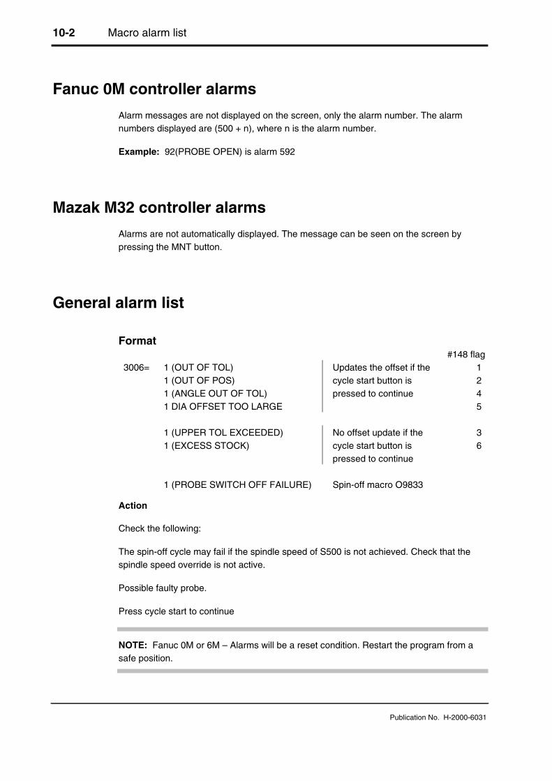
10-2 Macro alarm list
Publication No. H-2000-6031
Fanuc 0M controller alarms
Alarm messages are not displayed on the screen, only the alarm number. The alarmnumbers displayed are (500 + n), where n is the alarm number.
Example: 92(PROBE OPEN) is alarm 592
Mazak M32 controller alarms
Alarms are not automatically displayed. The message can be seen on the screen bypressing the MNT button.
General alarm list
Format#148 flag
3006= 1 (OUT OF TOL) 1 1 (OUT OF POS) 2 1 (ANGLE OUT OF TOL) 4 1 DIA OFFSET TOO LARGE
Updates the offset if thecycle start button ispressed to continue
5
1 (UPPER TOL EXCEEDED) 3 1 (EXCESS STOCK)
No offset update if thecycle start button ispressed to continue
6
1 (PROBE SWITCH OFF FAILURE) Spin-off macro O9833
Action
Check the following:
The spin-off cycle may fail if the spindle speed of S500 is not achieved. Check that thespindle speed override is not active.
Possible faulty probe.
Press cycle start to continue
NOTE: Fanuc 0M or 6M – Alarms will be a reset condition. Restart the program from asafe position.

Macro alarm list 10-3
Publication No. H-2000-6031
Format
#3000 = 101(PROBE START UP FAILURE) Spin-on macro O9832
Action
Check the following:
The spin-on cycle may fail if the spindle speed of S500 is not achieved. Check that thespindle speed override is not active.
Possible faulty probe.
This is a reset condition. Edit the program and start again from a safe start position.
Format
#3000 = 91 (MESSAGE)
91 (FORMAT ERROR)
91 (A INPUT MISSING)91 (B INPUT MISSING)91 (C INPUT MISSING)91 (D INPUT MISSING)91 (I INPUT MISSING)91 (J INPUT MISSING)91 (K INPUT MISSING)91 (X INPUT MISSING)91 (Y INPUT MISSING)91 (Z INPUT MISSING)91 (XYZ INPUT MISSING)
91 (DATA #130 TO #139 MISSING)
91 (X0 INPUT NOT ALLOWED)91 (Y0 INPUT NOT ALLOWED)91 (H INPUT NOT ALLOWED)91 (T INPUT NOT ALLOWED)91 (IJK INPUTS 5 MAX)
91 (XY INPUT MIXED)91 (XY INPUT MIXED)91 (ZK INPUT MIXED)91 (SH INPUT MIXED)91 (ST INPUT MIXED)91 (TM INPUT MIXED)91 (XYZ INPUT MIXED)
91 (K INPUT OUT OF RANGE)

10-4 Macro alarm list
Publication No. H-2000-6031
Action
Edit the program. This is a reset condition. Edit the program and start again from a safestart position.
Format
#3000 = 86(PATH OBSTRUCTED) protected positioning cycle only.
Action
Edit the program. This is a reset condition. Clear the obstruction and start again from asafe position.
Format
#3000 = 88(NO FEED RATE) protected positioning cycle only
Action
Edit the program. This is a reset condition. Insert the F___ code input, and start againfrom a safe position.
Format
#3000 = 89(NO TOOL LENGTH ACTIVE)
Action
Edit the program. This is a reset condition. G43 or G44 must be active before the cycle iscalled. Edit and start again from a safe position.
Format
#3000 = 92(PROBE OPEN) This alarm occurs if the probe isalready triggered before a move.
Action
Clear the fault. This is a reset condition. Clear the fault and start again from a safe startposition. The stylus may be in contact with a surface, or the probe has failed to reseat.This could be due to swarf trapped around the probe eyelid.
Format
#3000 = 93(PROBE FAIL) This alarm occurs if the probe didnot trigger during the move.

Macro alarm list 10-5
Publication No. H-2000-6031
Action
Edit the program. This is a reset condition. Edit the program and start again from a safestart position. The surface was not found or the probe has failed.
Optimisation macro only (O9836) alarms
Format
#3000 = 72(SKIP SIGNAL ALREADY ACTIVE) optimisation macro only.
This indicates that the machine skip signal is high prior to the probe move. Check that theprobe is active and that the interface is not in error. Check wiring. Check that the interfaceoutput relay is configured correctly, i.e. N/C or N/O. Is the stylus in contact with a surface?A possible reseat problem.
Action
Clear the fault
Format
#3000 = 73(NO SKIP SIGNAL DURING MOVE) optimisation macro only
The skip signal was not activated during the move. Check the wiring. Check probeoperation and interface LED outputs to confirm operation when the stylus is manuallydeflected. Also relay output voltage to skip when the probe is triggered.
Action
Edit the program
Format
#3000 = 74(H00 CODE TOOL LENGTH NOT ACTIVE) optimisation macro only.
The tool length offset must be set to zero by programming ‘H00’ prior to calling the macro.This permits the safe operation of jogging the stylus into a start position before running themacro.
Action
Edit the program

10-6 Macro alarm list
Publication No. H-2000-6031
Format
#3000 = 75(#118=BMCF DIST AND #119=FAST FEED) optimisation macro only.
This is the end of the optimisation cycle. The values in #118 and #119 can be installed(see "Optimising a probing cycle (O9836)" in Chapter 9, "Additional cycles" for details).
Action
Install setting values

Example job A-1
Publication No. H-2000-6031
Appendix A
Example job
Contained in this appendix
Introduction ......................................................................................................................A-2
Probe operations..............................................................................................................A-3
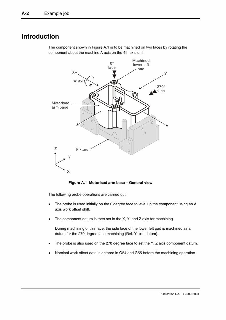
A-2 Example job
Publication No. H-2000-6031
Introduction
The component shown in Figure A.1 is to be machined on two faces by rotating thecomponent about the machine A axis on the 4th axis unit.
'A' axis
X+ Y+
270°face
0°face
Fixture
Motorisedarm base
Machinedlower left
pad
Z
Y
X
Figure A.1 Motorised arm base – General view
The following probe operations are carried out:
• The probe is used initially on the 0 degree face to level up the component using an Aaxis work offset shift.
• The component datum is then set in the X, Y, and Z axis for machining.
During machining of this face, the side face of the lower left pad is machined as adatum for the 270 degree face machining (Ref. Y axis datum).
• The probe is also used on the 270 degree face to set the Y, Z axis component datum.
• Nominal work offset data is entered in G54 and G55 before the machining operation.

Example job A-3
Publication No. H-2000-6031
Probe operations
%
O5866
(M-2116-0031-01-D)(MOTORISED ARM-BASE)(TAPE NO - T5866)(*)
(PROBE TO FIND CENTRE)
G17G94
G90G40G80
N10M00
(COMPONENT SET UP PROBING)(LOAD NOMINAL WORK OFFSETS)
/T30 Select the probe
/G91G28Z0A0 Retract
/G28A0 Position A axis
/G90 Absolute co-ordinates
Refer to Figure A.2 for probe movements 1 to 18
Z
X
Y
12
3
4
8
9
5
6
'A'
X+
10
11
15
14
17
18
16
Figure A.2 Probing operations on the 0-degree face
NOTE:The machine Z-axis is initiallyaligned with the 0-degree face

A-4 Example job
Publication No. H-2000-6031
1. /G00G54X90.Y0. Rapid positioning
2. /G43G1H30Z100.F3000 Go to Z 100 mm (3.94 in), apply tool offset.
3. /G65P9832 Spin the probe on.
4. /G65P9810Z10.F3000 Protected move to start position.
5. /G65P9818Y79.Z0S1. Set G54 A axis on the top face.
6. /G0A0 Level to new A axis position.
7. /#2802=#2801 Transfer G54 A axis to G55 A axis work offset.
8. /G65P9810Z-28.F3000. Protected move to position.
9. /G65P9812Y69.S1. Set G54 Y centre.
10. /G65P9810X-35.Y0 Protected move to position.
11. /G65P9811X-44.S1. Set G54 X position.
12. /#2502=#2501 Transfer G54 X axis to G55 X axis work offset.
13. /G65P9810X0 Protected move to position.
14. /G65P9810Z-84. Protected move to position.
15. /G65P9811Z-94.S1. Set G54 Z position.
16. /G65P9810Z100. Protected move retract.
17. /G65P9833 Spin the probe off.
18. /G91G28Z0
/G90
/M01
Continue machining 0-degree face
G0A-90. Index to 270 degree face.
N210(PROBE TO SET G55 Y Z)
/M01
/T30 Select probe.
/M09

Example job A-5
Publication No. H-2000-6031
/G91G28Z0
/G90
Refer to Figure A.3 for probe movements 20 to 30
Z
X
Y
'A'
X+
2021
2223
2425
2627
2829
30
270Face
o
Figure A.3 Probing operations on the 270-degree face
20. /G0G55X-38.0Y-74.0 Rapid positioning move
21. /G43G1H30Z100.F3000 Go to Z 100 mm (3.94 in), apply tool offset.
22. /G65P9832 Spin the probe on.
23. /G65P9810Z-5.F3000. Protected move to position.
24. /G65P9811Y-66.S2. Set G55 Y axis work offset.
25. /G65P9810X0Z10. Protected move to position.
26. /G65P9810Y-60. Protected moves to position.
27. /G65P9811Z0S2. Set G55 Z axis work offset.
28. /G65P9810Z100. Protected move retract.
29. /G65P9833 Spin the probe off.
30. /G91G28Z0 Retract
NOTE:The machine Z-axis is nowaligned with the 270-degree base

A-6 Example job
Publication No. H-2000-6031
/G90
/M01
Continue machining 270-degree face
G91G28Z0 Z return
G28X0Y0A0 X, Y, A return to start position.
G90
N420
M01
M30
%
Features, cycles and limitations B-1
Publication No. H-2000-6031
Appendix B
Features, cycles and limitations of theInspection Plus software
Contained in this appendix
Features of the Inspection Plus software.........................................................................B-2
Cycles ..............................................................................................................................B-2
Limitations ........................................................................................................................B-3Mazak M32 controller ...............................................................................................B-3Fanuc 10/11/12/15M controllers ...............................................................................B-4Fanuc 6M controller ..................................................................................................B-4Fanuc 0M controller ..................................................................................................B-4Fanuc 16M – 18M controllers ...................................................................................B-4
Limitations when using vector cycles O9821, O9822 and O9823 ...................................B-4Use of 3-point bore/boss macro O9823....................................................................B-5
Mathematical precision ....................................................................................................B-5
Effect of vector calibration data on results .......................................................................B-5

B-2 Features, cycles and limitations
Publication No. H-2000-6031
Features of the Inspection Plus software
● Protected positioning
● Measurement of internal and external features to determine both size and position.This includes:
● Obtaining a hardcopy printout of feature data
● Applying tolerances to both size and position
● Additional features for feedback of errors include:
● Experience values can be applied to the measured size
● Percentage feedback of the error can be applied
● Null band zone for no-tool offset update
● SPC (statistical process control) feedback based on average value
● Calculation of feature-to-feature data
● Measurement of external and internal corners for corner surfaces which may not beparallel to an axis
● Calibration of multiple styli
● 4th axis datum setting and tolerancing
● Angular measurement of features
● Software option to turn off the tolerance alarms and provide a flag-only alarm.Suitable for FMS and unmanned applications
● Built in stylus collision and false trigger protection for all cycles
● Diagnostic and format error checking routines for all cycles
Cycles
● Protected positioning
● Measurement:
● XYZ single surface
● Web/pocket

Features, cycles and limitations B-3
Publication No. H-2000-6031
● Bore/boss (four measuring points)
● Internal and external corner find
● Vectored measurement:
● 3-point bore/boss
● Web/pocket
● Single surface
● Additional macros:
● 4th axis measurement
● Bore/boss on a PCD
● Stock allowance
● Multi-stylus calibration
● XY plane angle measurement
Limitations
● The probe cycles will not run if ‘mirror image’ is active.
● The probe cycles will not run if ‘co-ordinate rotation’ is active.
● Consider macro variable availability.
● This software package can be used in the following controls.
Mazak M32 controller
The standard variables are sufficient.
Limitations
● None – ISO/EIA programming only.

B-4 Features, cycles and limitations
Publication No. H-2000-6031
Fanuc 10/11/12/15M controllers
Limitations
● #500 to #549 standard variable option.
● The use of multi-stylus data storage for vector calibration is not possible, unless theoption for extra variables is installed.
Fanuc 6M controller
Limitations
● #500 to #511 standard variables (no option).
● It not possible to use the multi-stylus macro option or the vector cycles.
Fanuc 0M controller
Limitations
● #500 to #531 standard variables (no option).
● It is not possible to use the multi-stylus macro to store vector calibration data (K11to K14).
Fanuc 16M – 18M controllers
Limitations
● None.
Limitations when using vector cycles O9821, O9822 andO9823
Vectored cycles involve the mathematical operation of squared values. This can lead toprecision errors if large values are used. The following factors must be considered:

Features, cycles and limitations B-5
Publication No. H-2000-6031
Use of 3-point bore/boss macro O9823
The macro may be used to establish the centre and diameter of a bore or external feature.There is however a practical limitation to the use of the macro. It is advisable to use thelargest distance between contacts, that is practical. The minimum conditions to givereliable data are as follows:
● 168 degrees total span.48 degrees between any two points.
● The software does not check the minimum condition inputs.
● The accuracy of the result deteriorates if the minimum conditions are not followed.
Mathematical precision
The mathematical precision of the controller is a limiting factor if large values are used.The Fanuc controller works within an accuracy of eight significant figures. Because of themathematical operations concerned, an error may accumulate if large values for probingpositions about the centre are used for calculation. It is suggested that, at this moment, XY coordinate values of ±300.00 mm (30.000 in) from the feature centre are not exceededfor any position around a bore, to retain a resultant resolution of better than 0.01 mm(0.001 in).
Effect of vector calibration data on results
The vector calibration cycle establishes true calibration data at each 30 degree increment.A small error due to the probe trigger characteristics may occur at intermediate anglesbetween the 30 degree calibration points. However this error is small for standardmachine tool probes with standard styli.
NOTE: For better accuracy, always use the standard bore/boss cycle (O9814) wherepossible.

B-6 Features, cycles and limitations
Publication No. H-2000-6031
This is page in intentionally left blank.

Settings macro details C-1
Publication No. H-2000-6031
Appendix C
Settings macro details
Contained in this appendix
Macro G65P9724.............................................................................................................C-2

C-2 Settings macro details
Publication No. H-2000-6031
Macro G65P9724
This macro is called at the beginning of all top level macros to establish the necessarymodal information.
The following data may be adjusted to suit during the installation by editing this macro.
The following values are supplied as standard:
#120 = 1 (SELECT OPTIONS) (see table below)
#123 = .05 (POSITION ZONE MM) This is the zone at either the start or end of theblock in which the cycle is aborted with eitherProbe Open or Probe Fail.
#119 = 5000 (FAST FEED MM) The fast feed rate of the cycles can be adjusted by#119 = 200 (FAST FEED INCH) this variable to suit the machine characteristics and
should be optimised.
NOTES:
1. The Z axis P9726 basic move macro fast feedrate is #119*.6, i.e. 3 metres/min asstandard.
2. All Z axis positioning moves are also #119*.6, i.e. 3 metres/min as standard.
3. All XY axis positioning moves are #119 value i.e. 5 metres/min as standard.
Select value for #120
Work offset type
Tool offset Tolerance alarm condition FS9 type10/11/12/15/M
FS6 type0/6/16/18M
A typeB typeC type
Flag and alarmsFlag and alarmsFlag and alarms
# 120=1# 120=2# 120=3
# 120=9# 120=10# 120=11
A typeB typeC type
FlagFlagFlag
# 120=5# 120=6# 120=7
# 120=13# 120=14# 120=15
Settings macro details C-3
Publication No. H-2000-6031
It is expected that the settings to enable ‘Flag only alarms’ will suit FMS machining cellswhere the requirement is to run unmanned. The process error flag #148 will be set and itshould be monitored after relevant probe cycles for corrective action (for use of extendedtool offsets, see Appendix J, "Tool offset macro 09732 and 09723").
Example
G65 P9812 X30.H.2 Set tolerance on measured size
IF[#148EQ1] GOTO999 Test for out of tolerance
continue part program
GOTO1000
N999 G65P5001 Pallet change. This changes the pallet to select the nextcomponent for machining (details are machine-dependent)
GOTO1 Go to start of program
N1000
M30

C-4 Settings macro details
Publication No. H-2000-6031
This page is intentionally left blank.

Tolerances D-1
Publication No. H-2000-6031
Appendix D
Tolerances
Contained in this appendix
Tolerances .......................................................................................................................D-2
True position tolerances...................................................................................................D-3

D-2 Tolerances
Publication No. H-2000-6031
Tolerances
Uu, Hh and Vv apply to size and tool offset updates only.
a
b
c
d
e+
_
Uu Hh tol
Vv input
a = Nominal size
b = Null band. This is the tolerance zone where no tool offset adjustment occurs.
c = Area where the Ff input is effective in percetage feedback. F (0 to 1) gives 0% to100% feedback to the tool offset
d = Hh 'Out of tolerance' alarm occurs. The tolerance value is that which is appliedto the size of the feature
e = Uu upper tolerance. If this value is exceeded there is no tool offset or work offsetupdated and the cyle is stopped with an alarm. This tolerance applies to bothsize and position where applicable.
Figure D.1 Size and tool offset update tolerances
Also see SPC macro O9835 (see Chapter 9, "Additional cycles") which can be used as amodified method for the feedback of tool offset corrections. Use this instead of Ff.

Tolerances D-3
Publication No. H-2000-6031
True position tolerances
For a true position tolerance (Mm input), see Figure D.2 below.
True position
Axis of datum Possible axes
Tol. 0.1(Mm input)
Figure D.2 Cylinders centred on true positions

D-4 Tolerances
Publication No. H-2000-6031
This page is intentionally left blank.
Experience values Ee E-1
Publication No. H-2000-6031
Appendix E
Experience values Ee
Contained in this appendix
Experience values Ee ......................................................................................................E-2
Reason for using this option ............................................................................................E-2

E-2 Experience values Ee
Publication No. H-2000-6031
Experience values Ee
The measured size can be adjusted by an amount stored in a spare tool offset.
Example
Measure a 40 mm diameter and update tool offset 20
G65P9814 D40. T20 E21 An experience value stored in tool offset 21 will beapplied to the measured size.
NOTE: The experience value is always added to themeasured size.
Also refer to Appendix F, "Additional spare tooloffsets".
Reason for using this option
Component clamping forces in some applications can influence the measured size.Therefore, an adjustment value to relate measurement to a traceable standard, such as aco-ordinate measuring machine, is desirable. Thermal effects can also be compensatedby this means.

Additional spare tool offsets F-1
Publication No. H-2000-6031
Appendix F
Additional spare tool offsets
Contained in this appendix
Additional spare tool offsets ............................................................................................. F-2

F-2 Additional spare tool offsets
Publication No. H-2000-6031
Additional spare tool offsets
The range of spare tool offsets can be extended when either a Type B or Type C tooloffset option is installed on the machine.
Figure F.1 shows the extra tool store locations.
Tool offset E1 to E____
Tool wear E201 to E2____
Tool radius E601 to E6____
Figure F.1 Spare tool offset location details
From the figure, you can see that you should add either 200 or 600 to the tool offsetnumber.
These additional tool offset registers can safely be used for both ‘Ee’ experience valuesand also with the SPC macro O9835 ‘Mm’ input provided. The tool offset number is notused as a normal tool offset location.
Type A
Type B
Type C

Printing a macro output G-1
Publication No. H-2000-6031
Appendix G
Printing a macro output
Contained in this appendix
Example of printing a macro output ................................................................................ G-2

G-2 Printing a macro output
Publication No. H-2000-6031
Example of printing a macro output
--------------------------------------------------------------------------COMPONENT NO 31 FEATURE NO 1--------------------------------------------------------------------------
POSNR79.0569 ACTUAL 79.0012 TOL TP 0.2000 DEV -0.0557POSN X-45.0000 ACTUAL -45.1525 TOL TP 0.2000 DEV -0.1525POSN Y-65.0000 ACTUAL -64.8263 TOL TP 0.2000 DEV 0.1737
+++++OUT OF POS+++++ ERROR TP 0.1311 RADIAL
ANG -124.6952 ACTUAL -124.8578 DEV -0.1626
---------------------------------------------------------------------------COMPONENT NO 31 FEATURE NO 2---------------------------------------------------------------------------
SIZE D71.0000 ACTUAL 71.9072 TOL 0.1000 DEV 0.9072
+++++OUT OF TOL+++++ ERROR 0.8072
POSN X-135.0000 ACTUAL -135.3279 DEV -0.3279POSN Y-65.0000 ACTUAL -63.8201 DEV 1.1799

Output flow H-1
Publication No. H-2000-6031
Appendix H
Output flow (bore/boss and web/pocketcycles)
Contained in this appendix
Output flow (bore/boss and web/pocket cycles) ..............................................................H-2

H-2 Output flow
Publication No. H-2000-6031
Output flow (bore/boss and web/pocket cycles)
Measure N10
If error flag#149 NEO If U input
If sizeerror
If E inputIf #149NE 2
If poserror
Size adjustexperience
Output variables#135 to #149
If H input Flag #148=3
If flag only#120.4=1
If sizeerror
If W input
Probeopen#3000
Upper tolexceeded
#3006Flag #148=1Print data to
RS232 port
If flag only#120.4=1
ENDN10
If sizeerror
Out of tol#3006
N13
Probe fail#3000
Y
Y
Y
Y
Y
N
N
N
N
N
#3000 alarms must reset machine#3006 cycle start to continue
N
N11

Output flow H-3
Publication No. H-2000-6031
N15
If T input
If V bandexceeded
If F input
Set F=1
If radiustoo large
If flag only#120.4=1
Out of tol#3006
N19
Y
N
Y
N13
If M input
If poserror
Flag #148=2
If flag only#148=1
If poserror
Out ofposition#3006
N15
Y
N
N
N
N19
If S input
Work offsetupdate
N
Update tool offseterror x F
Flag #148=5
END
N
N

H-4 Output flow
Publication No. H-2000-6031
This page is intentionally left blank.

Use of macro variables I-1
Publication No. H-2000-6031
Appendix I
Use of macro variables
Contained in this appendix
Local variables .................................................................................................................. I-2
Common variables ............................................................................................................ I-2
Common retained variables .............................................................................................. I-3

I-2 Use of macro variables
Publication No. H-2000-6031
Local variables
#1 to #32 These are used within each macro as required for calculation etc.
Common variables
#100 to #115 Are NOT used by this software.
#116 Active tool length - calculated in macro O9723.
#117 Modal feedrate value is used in the protected positioning macro (O9810).
#118 Radius too large flag macro O9812, O9814, O9822, O9823 (also used fortemporary ATAN store in macro O9731).
#119 Fast feed rate value. This is set in macro O9724 at 5000 mm/min(200 in/min) default value.
#120 Setting variable used in macro O9724.
#121 Print, component number (6-digit) increment by 1, with each headingprogram #121 = 0 to reset.
#122 Feature number (4-digit) increment by 1, with each print macro callprogram #122 = 0 to reset.
#123 Start and end of block position zone normal setting 0.05 mm (0.002 in). Ifthe skip position is within this zone, the cycle aborts, with a Probe Openor Probe Fail alarm.
#124 Stored X skip position at the end of the basic move macro O9726
#125 Stored Y skip position at the end of the basic move macro O9726.
#126 Stored Z skip position at the end of the basic move macro O9726.
#127 X average skip position at the end of the X diameter move macro O9721.
#128 Y average skip position at the end of the Y diameter move macro O9722.
#129 Inch/metric multiplier (0.04/1.0)
#130 to #134 Output data #135 to #139 is stored when the feature-to-feature macroO9834 is used.
#135 to #149 See Chapter 4, "Variable outputs", for an output reference chart.

Use of macro variables I-3
Publication No. H-2000-6031
#150 onwards Are NOT used by the software.
Common retained variables
#500 (XRAD) X calibration radius
#501 (YRAD) Y calibration radius
#502 (XOFF) X axis stylus offset
#503 (YOFF) Y axis stylus offset
#504 (Reserved for other software packages)
#505 (Reserved for other software packages)
#506 Basic move control factor. This is used to control the back-off distance inthe basic move before the final gauge move. It should be fine tuned oninstallation to suit the machine. Refer to Figure I.1 for a diagrammaticrepresentation.
A default value of 0.5 is installed by the software. The actual factor shouldnormally be between 0 and 1.0. Reduce the value to reduce the back-offdistance.
NOTE: This value can be found by using the optimisation macro O9836. The value mustbe set in the settings macro O9724.
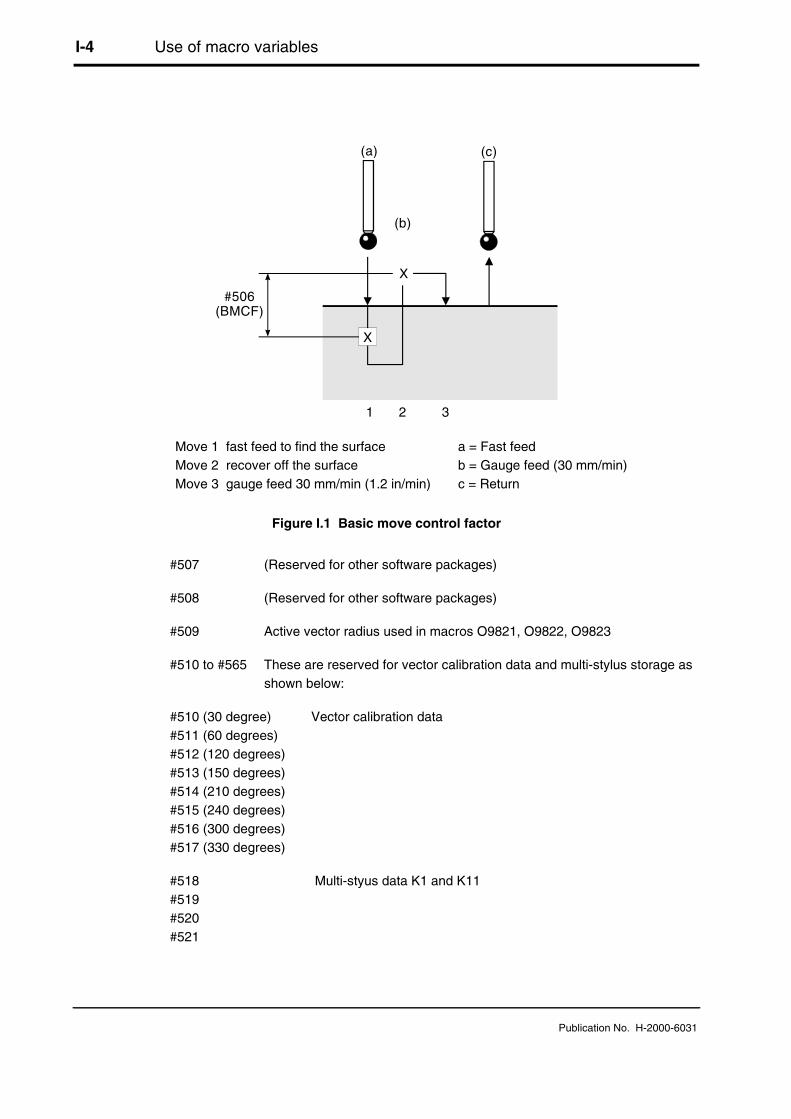
I-4 Use of macro variables
Publication No. H-2000-6031
(a)
#506(BMCF)
(b)
X
1 2 3
(c)
X
Figure I.1 Basic move control factor
#507 (Reserved for other software packages)
#508 (Reserved for other software packages)
#509 Active vector radius used in macros O9821, O9822, O9823
#510 to #565 These are reserved for vector calibration data and multi-stylus storage asshown below:
#510 (30 degree) Vector calibration data#511 (60 degrees)#512 (120 degrees)#513 (150 degrees)#514 (210 degrees)#515 (240 degrees)#516 (300 degrees)#517 (330 degrees)
#518 Multi-styus data K1 and K11#519#520#521
Move 1 fast feed to find the surface a = Fast feedMove 2 recover off the surface b = Gauge feed (30 mm/min)Move 3 gauge feed 30 mm/min (1.2 in/min) c = Return

Use of macro variables I-5
Publication No. H-2000-6031
#522 Multi-styus data K2 and K12#523#524#525
#526 Multi-stylus data K3 and K13#527#528#529
#530 Multi-stylus data K4 and K14#531#532#533
#534 Vector multi-stylus data K11#535#536#537#538#539#540#541
#542 Vector multi-stylus data K12#543#544#545#546#547#548#549
#550 Vector multi-stylus data K13#551#552#553#554#555#556#557

I-6 Use of macro variables
Publication No. H-2000-6031
#558 Vector multi-stylus data K14#559#560#561#562#563#564#565
The actual variables available are the limiting factor and depend on the control optionsavailable.
Tool offset macros O9732 and O9723 J-1
Publication No. H-2000-6031
Appendix J
Tool offset macros O9732 and O9723
Contained in this appendix
Introduction ...................................................................................................................... J-2
Editing macro O9732 ....................................................................................................... J-2
Editing macro O9723 ....................................................................................................... J-2
J-2 Tool offset macro O9732 and O9723
Publication No. H-2000-6031
Introduction
Macros O9732 and O9723 are used to address the correct tool offset registers duringmacro execution.
The macro uses the #2--- system variables, which permit access to the 200 tool offsetoption.
Additional tool offsets can be addressed by changing the system variable numbers to#10--- type, when available.
Editing macro O9732
Edit macro O9732 as follows:
O9732 (REN OFFSET TYPE)
#27 = 2000 (L WEAR 10000)#28 = 2200 (L G-W 11000) Numbers in brackets are the alternative#29 = 2600 (R WEAR 12000) system variable numbers#30 = 2400 (R GEOM 13000)
macro continued
Editing macro O9723
Edit macro 09723 as follows:
O9723 (REN ACT OFFSET)
#27 = 2000 (L wear 10000) Numbers in brackets are the alternative#28 = 2200 (L G-W 11000) system variable numbers.
In cases where more than 200 tool offsets are available, it is necessary to use thealternative system variable numbers.

General probing applications K-1
Publication No. H-2000-6031
Appendix K
General probing applications
Contained in this appendix
Example 1 – Part identification.........................................................................................K-2
Example 2 – Probe measure every nth component.........................................................K-3
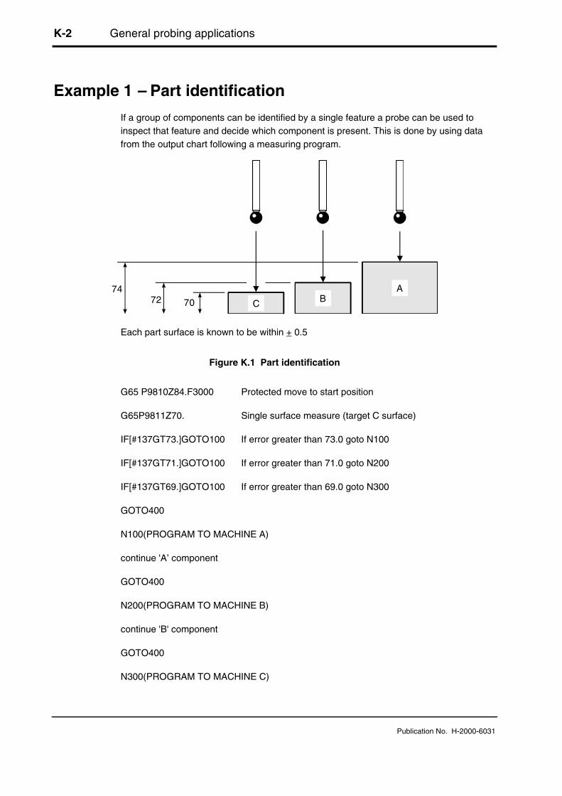
K-2 General probing applications
Publication No. H-2000-6031
Example 1 – Part identification
If a group of components can be identified by a single feature a probe can be used toinspect that feature and decide which component is present. This is done by using datafrom the output chart following a measuring program.
7472 70 C B
A
Each part surface is known to be within + 0.5
Figure K.1 Part identification
G65 P9810Z84.F3000 Protected move to start position
G65P9811Z70. Single surface measure (target C surface)
IF[#137GT73.]GOTO100 If error greater than 73.0 goto N100
IF[#137GT71.]GOTO100 If error greater than 71.0 goto N200
IF[#137GT69.]GOTO100 If error greater than 69.0 goto N300
GOTO400
N100(PROGRAM TO MACHINE A)
continue 'A’ component
GOTO400
N200(PROGRAM TO MACHINE B)
continue 'B' component
GOTO400
N300(PROGRAM TO MACHINE C)

General probing applications K-3
Publication No. H-2000-6031
continue 'C' component
N400
M30
%
Example 2 – Probe measure every nth component
It is often a requirement to probe every nth component in the interests of reducing overallcycle time.
The following programming method can be employed:
O5000(PART PROGRAM)
#100=0 Reset counter
#101=5 Count limit
N1
(START OF MACHINING)
conventional part programming
N32
(START OF PROBE ROUTINES)
IF[#100LT#105]GOTO33 If counter less than 5 jump to N33
T01M06 (PART INSPECTION) Select inspection probe
probing routines
#100=0 Reset counter to zero
N33
(CONTINUE MACHINING OR END)
#100=#100+1 Increment counter
rest of machining program
M99P1 Return to N1

K-4 General probing applications
Publication No. H-2000-6031
M30
%

One-touch measuring L-1
Publication No. H-2000-6031
Appendix L
One-touch measuring
Contained in this appendix
Introduction ...................................................................................................................... L-2Why use a one-touch probe cycle? .......................................................................... L-2Using the high speed skip option.............................................................................. L-2
Machine distortion.............................................................................................. L-2Servo delays...................................................................................................... L-3
Comparing cycle times ............................................................................................. L-3
Installing the one-touch cycles......................................................................................... L-4Macro edits ............................................................................................................... L-4
Measuring the feedrate...................................................................................... L-5Stand-off and overtravel distance...................................................................... L-5
System operation ............................................................................................................. L-5Using standard skip .................................................................................................. L-5Additional variables used.......................................................................................... L-6Approach feedrates .................................................................................................. L-6Back-off distance #506 ............................................................................................. L-6False trigger loop ...................................................................................................... L-6Acceleration and deceleration allowance.................................................................. L-6Q input ...................................................................................................................... L-8Measuring move detail.............................................................................................. L-8One-touch measuring move logic ............................................................................. L-9

L-2 One-touch measuring
Publication No. H-2000-6031
Introduction
The Inspection Plus software package provides an optional one-touch measuringcapability to supplement the standard two-touch cycles. The one-touch cycles areintended for use on machines with a fast probe trigger detection ability so that highmeasuring feedrates can be used.
The Inspection Plus software (Renishaw part no A-4012-0516) comprises the following:
Disk assembly A-4012-0518
Two-touch probe cycles 401205194012052040120521
Files
Additional one-touch probe cycles(macro O9726 only)
40120727
Table L-1 Inspection Plus software kit
Why use a one-touch probe cycle?
A one-touch cycle offers the benefit of reduced cycle times and fewer probe triggers percycle. It can be used in the following circumstances:
● On machines fitted with fast probe trigger signal detection (ie the high speed skipoption - see below)
● When the nominal surface position is known to within a small window of uncertainty
Using the high speed skip option
This makes it possible to probe at high feedrates of typically 1 m/min without any loss ofmeasuring accuracy, provided the surface is hit at a constant velocity. When this cannotbe relied on, the following must be considered:
Machine distortion
The machine is under stress during acceleration and deceleration and therefore therecorded trigger values may have errors depending on machine tool condition.

One-touch measuring L-3
Publication No. H-2000-6031
Servo delays
Normally the axis servo delays are included in the result unless steps are taken toaccount for it. Refer to your machine parameter manual for setting information so thatthese errors are considered and compensated for.
Examples:
Fanuc 15
Setting parameter 7300.7=1 (SEB) will enable this function
Fanuc 16/18
Setting parameter 6201.1=1 (SEB) will enable this function
NOTE: When not fitted as standard, the high speed skip option may not be easilyretrofitted to a machine because of hardware and configuration requirements.
Fanuc 0
Setting parameter - none available
Comparing cycle times
A program was prepared to perform five surface measurements as follows:
● Start 50 mm above the ring gauge
● Measure a 50 mm bore at 5 mm deep (four cardinal points)
● Retract to 5 mm above, move over and make a Z measure on top of the ring gauge.
● Retract to 50 mm and return to the centre
Table L-2 below shows cycle time comparisons only. Check for suitable measuringfeedrates on your machine.

L-4 One-touch measuring
Publication No. H-2000-6031
Time inseconds @500 mm/min
Time inseconds @120 mm/min
Time inseconds @60 mm/min
Time inseconds @30 mm/min
Two-touch cycles - - - 27.6
One-touch cycle:
Stand-offdistance
0.51.02.03.0
18.018.218.719.1
18.519.822.424.4
20.022.227.432.2
22.427.337.147.0
Table L-2 Cycle time comparison
Installing the one-touch cycles
NOTE: The new one-touch basic move macro O9726 is only compatible with thesoftware supplied with this package. Previous versions are not compatible.
Before installing the one-touch cycles, the standard two-touch cycles must already havebeen installed.
The one-touch cycles file (40120727.**) contains a new one-touch macro O9726. Thisshould be loaded once the existing two-touch macro O9726 has been deleted frommemory.
Macro edits
The macro O9726, shown below, may be edited for measuring feedrate and stand-off/overtravel distance values:
:9726(REN BASIC MEASURE - 1T)#9=500*#129(EDIT MEAS FEED) .... * Feed - edit 500 value#28=#9/1000(EDIT ZONE) .... accel / deceleration zone#31=0IF[#17NE#0]GOTO2#17=3*#129(EDIT) ....... * stand off - edit 3 valueN2
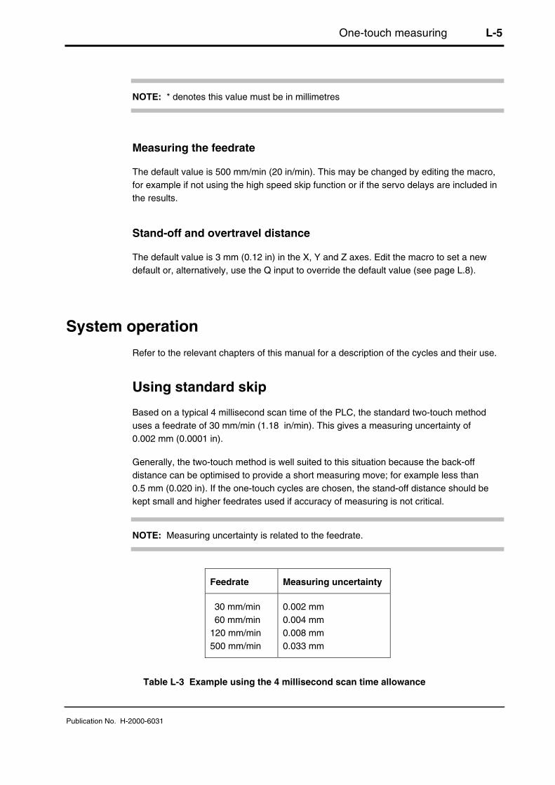
One-touch measuring L-5
Publication No. H-2000-6031
NOTE: * denotes this value must be in millimetres
Measuring the feedrate
The default value is 500 mm/min (20 in/min). This may be changed by editing the macro,for example if not using the high speed skip function or if the servo delays are included inthe results.
Stand-off and overtravel distance
The default value is 3 mm (0.12 in) in the X, Y and Z axes. Edit the macro to set a newdefault or, alternatively, use the Q input to override the default value (see page L.8).
System operation
Refer to the relevant chapters of this manual for a description of the cycles and their use.
Using standard skip
Based on a typical 4 millisecond scan time of the PLC, the standard two-touch methoduses a feedrate of 30 mm/min (1.18 in/min). This gives a measuring uncertainty of0.002 mm (0.0001 in).
Generally, the two-touch method is well suited to this situation because the back-offdistance can be optimised to provide a short measuring move; for example less than0.5 mm (0.020 in). If the one-touch cycles are chosen, the stand-off distance should bekept small and higher feedrates used if accuracy of measuring is not critical.
NOTE: Measuring uncertainty is related to the feedrate.
Feedrate Measuring uncertainty
30 mm/min60 mm/min
120 mm/min500 mm/min
0.002 mm0.004 mm0.008 mm0.033 mm
Table L-3 Example using the 4 millisecond scan time allowance

L-6 One-touch measuring
Publication No. H-2000-6031
Additional variables used
The following additional variables are used by this software:
#124 This is used to store the X axis measured skip position. The value is set inmacro O9726.
#125 This is used to store the Y axis measured skip position. The value is set inmacro O9726.
#126 This is used to store the Z axis measured skip position. The value is set inmacro O9726.
Approach feedrates
The feedrate for the approach to the stand-off position in macro O9726 is set at3000 mm/min (120 in/min) in the X, Y and Z axes.
Back-off distance #506
This variable is not used in the one-touch cycles.
False trigger loop
At the end of the measuring move a false trigger test is made to see if the probe istriggered against a surface. If the probe has reseated, the measuring move continues.Four attempts are made before a PROBE OPEN alarm occurs.
Acceleration and deceleration allowance
To avoid the possibility of capturing bad data (see Machine distortion and Servo delays onpage L-2 and L-3), the one-touch basic move sets a checking zone dimension at the startand end of the measuring move. If the data captured is within these zones, a PROBEOPEN or PROBE FAIL alarm is generated.
The zone dimension is related to the feedrate and is currently set as follows:
zone dimension = measuring feedrate / 1000(ie zone factor = 1000)
NOTE: See Macro edits on page L-4 for details of setting the measuring feedrate.
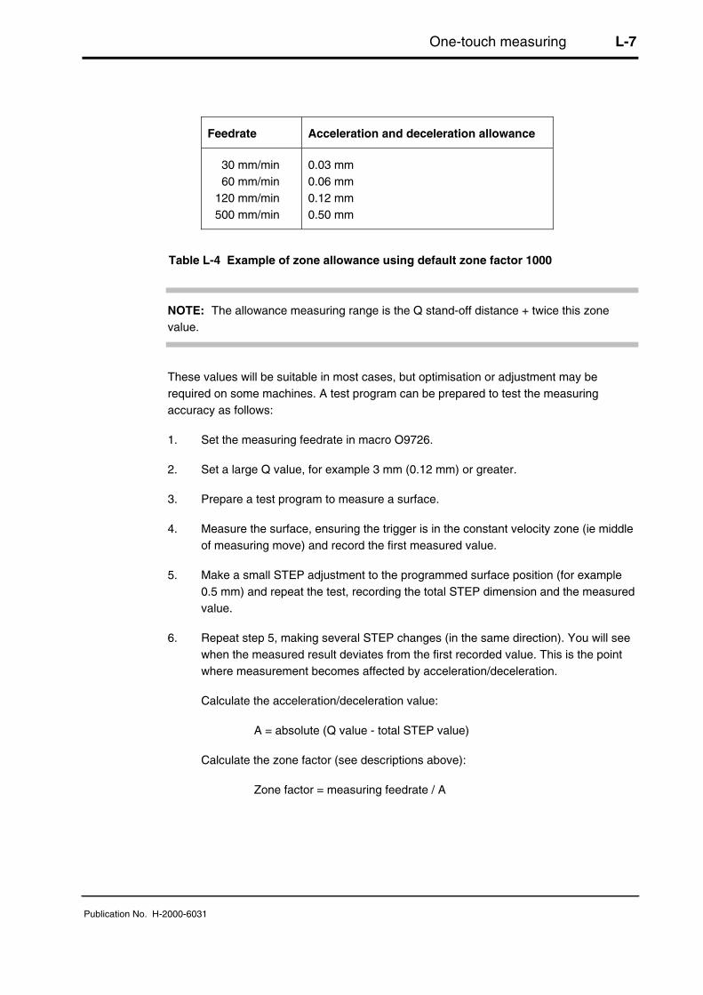
One-touch measuring L-7
Publication No. H-2000-6031
Feedrate Acceleration and deceleration allowance
30 mm/min60 mm/min
120 mm/min500 mm/min
0.03 mm0.06 mm0.12 mm0.50 mm
Table L-4 Example of zone allowance using default zone factor 1000
NOTE: The allowance measuring range is the Q stand-off distance + twice this zonevalue.
These values will be suitable in most cases, but optimisation or adjustment may berequired on some machines. A test program can be prepared to test the measuringaccuracy as follows:
1. Set the measuring feedrate in macro O9726.
2. Set a large Q value, for example 3 mm (0.12 mm) or greater.
3. Prepare a test program to measure a surface.
4. Measure the surface, ensuring the trigger is in the constant velocity zone (ie middleof measuring move) and record the first measured value.
5. Make a small STEP adjustment to the programmed surface position (for example0.5 mm) and repeat the test, recording the total STEP dimension and the measuredvalue.
6. Repeat step 5, making several STEP changes (in the same direction). You will seewhen the measured result deviates from the first recorded value. This is the pointwhere measurement becomes affected by acceleration/deceleration.
Calculate the acceleration/deceleration value:
A = absolute (Q value - total STEP value)
Calculate the zone factor (see descriptions above):
Zone factor = measuring feedrate / A
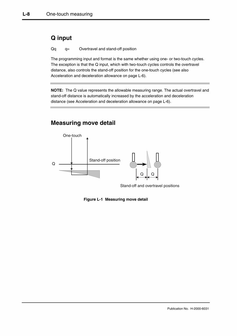
L-8 One-touch measuring
Publication No. H-2000-6031
Q input
Qq q= Overtravel and stand-off position
The programming input and format is the same whether using one- or two-touch cycles.The exception is that the Q input, which with two-touch cycles controls the overtraveldistance, also controls the stand-off position for the one-touch cycles (see alsoAcceleration and deceleration allowance on page L-6).
NOTE: The Q value represents the allowable measuring range. The actual overtravel andstand-off distance is automatically increased by the acceleration and decelerationdistance (see Acceleration and deceleration allowance on page L-6).
Measuring move detail
Q
One-touch
Stand-off position
Stand-off and overtravel positions
Figure L-1 Measuring move detail

One-touch measuring L-9
Publication No. H-2000-6031
One-touch measuring move logic
Start
IFshortmove
Measuremove
Store position
END
Move tostand-offposition
IF probefail
IF probeopen
Falsetriggermovecheck
IF falsetrigger
loop > 4
Return to start
IF falsetrigger
Alarms
Y
Y
Y
Y

L-10 One-touch measuring
Publication No. H-2000-6031
This page is intentionally left blank.

Glossary of terms GLY-1
Publication No. H-2000-6031
Glossary of terms - abbreviations anddefinitions
Definitions of many of the terms used are provided here to assist your understanding ofthe Inspection Plus software.
NOTE: This glossary also includes terms that are associated with probing but which havenot been used in this publication.
ATAN calculation
This describes a user transparent macro written by Renishaw to handle the ATANfunction in mathematical calculations.
User transparent
Macros which are used by the software but which do not get called directly by the user,i.e. they are for internal use by the software only.
BRDO
Ball radius directional offsets. This is a term that is used to describe the stored softwarecompensations for the stylus ball radius. They are determined during calibration of theprobe.
Bore/boss measure
This is a Renishaw measuring cycle type definition.
Bore – is an internal-width feature measurement on a circle. Feature types consist ofholes or bores.
Boss – this is an external-width feature measurement on a circle. Feature types consist ofshafts, bosses, and spigots.
Calibration
This is the method of establishing the probe trigger point compensations. They include theprobe and machine effects which the software must use to correct the results.
C.W.
Clockwise

GLY-2 Glossary of terms
Publication No. H-2000-6031
C.C.W.
Counter-clockwise.
Datum, datuming
This is the method used to establish a part feature reference point which is subsequentlyused for other measurement or machining operations. A datum defines any co-ordinatevalue as a reference position.
DPRNT
This is a Fanuc control command. It outputs ASCII data to the RS-232 port of thecontroller. It is used to output a part inspection report that is based on probe results.
DTI
Dial test indicator. This instrument is traditionally used for aligning vices and fixtures withrespect to the machine axis.
Gauging move
This describes the movement of the probe onto the surface with data capture active, i.e. itis a measurement move.
IMM
Inductive module machine. Together with the IMP, it forms part of the inductivetransmission system that is used to transmit signals back to the machine tool controller.The IMM is part of the inductive coupling and is mounted on the machine. See also IMP.
IMP
Inductive module probe. Together with the IMM, it forms part of the inductivetransmission system that is used to transmit signals back to the machine tool controller.The IMP is part of the inductive coupling and is mounted on the probe. See also IMM.
INHIBIT
This is a Renishaw interface input signal. It is used to either stop or inhibit thetransmission of the probe signal to the machine controller.
MDI
Manual data input. This is a commonly used term on Fanuc controllers (and controllersthat emulate the Fanuc). It means that operation of the machine is determined by datathat is entered through the keyboard.
MMS menu cycles
Mazatrol monitoring system. This is a standard Mazak probe option unit that is normallyfitted as original equipment.
Glossary of terms GLY-3
Publication No. H-2000-6031
MI5 interface
This is the Renishaw probe interface that is used to condition and control the probe signalto the machine tool.
M19 spindle orientation
This is the machine manufacturer’s M-code function that instructs the machine spindle torotate and orientate to a fixed position.
Nominal surface position
This is the expected surface position, or theoretical position. When used in relation totolerances, it refers to the mid-position of the upper and lower limit of the surface.
OMI
Optical module interface. This is a combined optical receiver and machine interface unitthat forms part of the Renishaw optical probe transmission system. The unit is mountedeither on the guarding or some other suitable position where it is within the transmissionenvelope and range of the probe.
OMM
Optical module machine. This is part of the Renishaw optical probe transmissionsystem. The unit is mounted either on the guarding or some other suitable position whereit is within the transmission envelope and range of the probe.
OMP
Optical module probe. This is part of the Renishaw optical probe transmission system.The unit is mounted on the probe unit.
Optimisation macro
This is part of the Renishaw software package. It is used to establish the optimum fastfeed rates for probing and the optimum back-off distance.
PCD
Pitch circle diameter. This is a commonly used British term to mean a set of featuresplaced in a circular pattern.
Probe trigger flag
This is a variable or diagnostic register which is set to a value when the probe is triggered.
Protected positioning
This is a means of moving the probe from place to place while the probe trigger signal ismonitored. In the event of an unexpected triggering signal, the machine axis is halted toprevent damage to the probe stylus.

GLY-4 Glossary of terms
Publication No. H-2000-6031
PTR
Paper tape reader. This is the machine’s interface which is used to load the stored partprograms. It is now largely superseded by the use of floppy disk drives, external PCs, andthe RS-232 serial interface.
RMM
Receiver module machine. This is part of the Renishaw radio probe transmissionsystem. The unit is mounted either on the guarding or some other suitable position whereit is within the transmission envelope and range of the probe.
RMP
Radio module probe. This is part of the Renishaw radio probe transmission system. Theunit is mounted on the probe.
SPC
Statistical process control. Some Renishaw software packages contain a macro whichuses a simple form of SPC to control tool offset update corrections in closed loopmachining.
Stylus
This is the probe tip assembly that is used to trigger the probe on the tool duringmeasurement.
SSR
Solid state relay. The SSR converter terminal block is a Renishaw hardware unit which isused to convert the signal from a signal conditioning module into an SSR output signal.
Tolerance limits
These are the extreme upper and lower metal condition values from the nominal surfaceposition.
Vector cycle, vector measure/calibration
This is a probe move, which move one or more machine axes simultaneously to approachthe surface from the normal direction.
Vector stylus ball radius calibration
This is an extra set of probe stylus ball radius calibration values which must bedetermined when using vector cycles. They are the probe software compensation valuesrequired for probing in different directions.

Glossary of terms GLY-5
Publication No. H-2000-6031
Web/pocket measure
This describes a Renishaw measuring cycle type definition.
Pocket – is an internal-width feature measurement. Feature types consist of slots,pockets, and internal recesses.
Web – is an external-width feature measurement. Feature types consist of blocks, platewidths, and upstanding keys.
Work zero point
This is a similar concept to Datum. It defines where the work co-ordinate system is set tozero. A datum can define any co-ordinate value as a reference position.
Workpiece datum
This can be any workpiece feature or co-ordinate, which is chosen as a referenceposition.

GLY-6 Glossary of terms
Publication No. H-2000-6031
This page is intentionally left blank.

Renishaw plc
New Mills, Wotton-under-Edge,Gloucestershire, GL12 8JRUnited Kingdom
T +44 (0)1453 524524F +44 (0)1453 524901E [email protected]
www.renishaw.com
For worldwide contact details,please visit our main website at
www.renishaw.com/contact
*H-2000-6031-0C-A*


![OMP40-2 Installation Guide[1]](https://img.dokumen.tips/doc/110x75/544e6b9ab1af9f27638b4dea/omp40-2-installation-guide1.jpg)

