Embed Size (px)
Citation preview


CONFORMANCE TO STANDARDSThe OMNI R2 meter meets and far exceeds the most recent revision of ANSI/AWWA Standard C701 class II standards and exceeds ANSI/AWWA C700 Residential Standard using Sensus Turbo technology. Each meter is performance tested to ensure compliance. All OMNI meters are NSF/ANSI Standard 61, Annex F and G approved.
PERFORMANCEThe patented measurement principles of the OMNI R2 meter assure enhanced accuracy ranges, an overall greater accuracy, and a longer service life than any other comparable class meter produced. The OMNI R2 meter has no restrictions as to sustained flow rates within its continuous operating range. The floating ball measurement technology allows for flows up to its rated maximum capacity without affecting undue wear or accuracy degradation when installed in any orientation.
CONSTRUCTIONThe OMNI R2 meter consists of two basic assemblies; the maincase and the measuring chamber. The measuring chamber assembly includes the “floating ball” impeller with a coated titanium shaft, hybrid axial bearings, integral flow straightener and an all electronic programmable register with protective bonnet. The maincase is made from industry proven Ductile Iron with an
approved NSF epoxy coating. Maincase features are; easily removable measuring chamber, unique chamber seal to the maincase using a high pressure o-ring, testing port and a convenient integral strainer.
OMNI ELECTRONIC REGISTERThe OMNI R2 electronic register consist of a hermetically sealed register with an electronic pickup containing no mechanical gearing. The large character LCD displays AMR, Totalization and a Resettable Test Totalizer. OMNI register features; AMR resolution units that are fully programmable, Large, easy-to-read LCD also displays both forward and reverse flow directions and all with a 10-year battery life guarantee.
MAGNETIC DRIVEMeter registration is achieved by utilizing a fully magnetic pickup system. This is accomplished by the magnetic actions of the embedded rotor magnets and the ultra sensitive register pickup probe. The only moving component in water is the “floating ball” impeller.
MEASURING ELEMENTThe revolutionary thermoplastic, hydro dynamically balanced impeller floats between the bearings. The Floating Ball Technology (FBT) allows the measuring element to operate virtually without friction or wear, thus creating the extended upper and lower flow ranges capable on only the OMNI R2 meter.
STRAINERThe OMNI R2 with the “V” shaped integral strainer using a stainless steel screen along with Floating Ball Technology (FBT) create a design that gives far improved accuracy even in those once thought questionable settings. A removable strainer cover permits easy access to the screen for routine maintenance.
MAINTENANCEThe OMNI R2 meter is designed for easymaintenance. Should any maintenance be required, the measuring chamber and/or strainer cover can be removed independently. Parts and or a replacement measuring chamber may be utilized in the event repairs are needed. Replacement Measuring Chambers are available for the OMNI R2 meters and may be utilized for retrofitting to competitive meters to achieve increased accuracy and extended service life.
AMR / AMI SYSTEMSMeters and encoders are compatible with current Sensus AMR/AMI systems.
GUARANTEE Sensus OMNI R2 Meters are backed by “The Sensus Guarantee.” Ask your Sensus representative for details or see Bulletin G-500.
Features
Description1-1/2” and 2” Sizes
The OMNI R2 meter operation is based on advanced Floating Ball Technology (FBT).
DS-W-OMR-00-00-0611-03-A
OMNITM R2
1-1/2” and 2” OMNI R2 Meter
AMR/AMI Mode
Totalization Mode
Resettable Test Mode

DS-W-OMR-00-00-0611-03-APage 2 of 3
OMNI R2: 1-1/2” and 2”Sizes
DIMENSIONS AND NET WEIGHTS
Meter and Pipe Size
Normal Operating Range
Connec-tions A B C D E F G H J Net
WeightShipping Weight
1-1/2” DN 40mm
2 gpm.45 m3/hr
150 gpm 34 m3/hr
Flanged13”
330mm7-7/8”
200mm15/16” 24mm
5-1/8” 130mm
2-5/16” 59mm
4” 102mm 2
5/8” 16mm
1” 25mm
18.8 lbs. 8.53 kg..
22.5 lbs. 10.20 kg.
2” DN 50mm
2.5 gpm .56 m3/hr
200 gpm 45 m3/hr
Flanged17”
432mm7-7/8”
200mm1”
25mm5-3/4”
146mm2-5/16” 59mm
4-1/2” 114mm 2
3/4” 19mm
1” 25mm
27.4 lbs. 12.42 kg.
34.5 lbs. 15.65 kg.
2” without Strainer
DN 80mm
2.5 gpm .56 m3/hr
250 gpm 57 m3/hr
Flanged 10” 254mm
7-7/8” 200mm
1” 25mm
5-3/4” 146mm
2-5/16” 59mm
4-1/2” 114mm 2 3/4”
19mm1”
25mm17 lbs. 7.9 kg.
24.5 lbs. 11.11 kg.

8601 Six Forks Road, Suite 700Raleigh, NC 276151-800-638-3748www.sensus.com/water
© All products purchased and services performed are subject to Sensus’ terms of sale, available at either; http://na.sensus.com/TC/TermsConditions.pdf or 1-800-METER-IT. Sensus reserves the right to modify these terms and conditions in its own discretion without notice to the customer.
This document is for informational purposes only, and SENSUS MAKES NO EXPRESS WARRANTIES IN THIS DOCUMENT. FURTHERMORE, THERE ARE NO IMPLIED WARRANTIES, INCLUDING WITHOUT LIMITATION, WARRANTIES AS TO FITNESS FOR A PARTICULAR PURPOSE AND MERCHANTABILITY. ANY USE OF THE PRODUCTS THAT IS NOT SPECIFICALLY PERMITTED HEREIN IS PROHIBITED.
DS-W-OMR-00-00-0611-03-APage 3 of 3
SERVICE Measurement of potable and reclaim water. Operating temperature range of 33 oF (.56 oC) - 150 oF (65.6 oC)
OPERATINGRANGE(100% ± 1.5%)
1-1/2”: 2 – 150 GPM (.45 - 34 m3/hr)2”: 2.5 – 200 GPM (.56 – 45 m3/hr)2” without Strainer: 2.5 – 200 GPM (.56 – 45 m3/hr)
LOW FLOW(95% – 101.5%)
1-1/2”: .75 GPM (.17 m3/hr)2”: 1.0 GPM (.23 m3/hr)2” without Strainer: 1.0 GPM (.23 m3/hr)
PRESSURE LOSS
1-1/2”: 6.7 psi @ 150 GPM (0.46 bar @ 34 m3/hr)2”: 7.0 psi @ 200 GPM (.48 bar @ 45 m3/hr)
MAXIMUM OPERATING PRESSURE
200 PSI (13.8 bar)
FLANGE CONNECTIONS U.S. ANSI B16.1 / AWWA Class 125
REGISTER Fully electronic sealed register with programmable registration (Gal. /Cu.Ft./ Cu. Mtr. / Imp.Gal / Acre Ft.)Programmable AMR/AMI reading Guaranteed 10 year battery life
NSF APPROVED MATERIALS
Maincase: Measuring Chamber: Rotor “Floating Ball”: Radial Bearings: Thrust Bearings: Magnets: Strainer Screen: Strainer Cover: Test Plug:
Coated Ductile IronThermoplastic ThermoplasticHybrid ThermoplasticSapphire/Ceramic Jewel Ceramic MagnetStainless SteelCoated Ductile IronCoated Ductile Iron
SPECIFICATIONS
OMNI R2: 1-1/2” and 2” Sizes
Headloss Curves
CONFORMANCE TO STANDARDS
The OMNI T2 meter meets and far ex-
ceeds the most recent revision of AWWA
Standard C701 class II standards. Each
meter is performance tested to ensure
compliance. All OMNI meters are NSF/
ANSI Standard 61, Annex F and G ap-
proved.
PERFORMANCE
The patented measurement principles
of the OMNI T2 meter assure enhanced
accuracy ranges, an overall greater ac-
curacy, and a longer service life than any
other comparable class meter produced.
The OMNI T2 meter has no restrictions
as to sustained fl ow rates within its con-
tinuous operating range. The fl oating ball
measurement technology allows for fl ows
up to its rated maximum capacity without
affecting undue wear or accuracy degra-
dation when installed in any orientation.
CONSTRUCTION
The OMNI T2 meter consists of two basic
assemblies; the maincase and the mea-
suring chamber. The measuring chamber
assembly includes the “fl oating ball” im-
peller with a coated titanium shaft, hybrid
axial bearings, integral fl ow straightener
and an all electronic programmable regis-
ter with protective bonnet. The maincase
is made from industry proven Ductile Iron
with an approved NSF epoxy coating.
Maincase features are; easily removable
measuring chamber, unique chamber
seal to the maincase using a high pres-
sure o-ring, testing port and a convenient
integral strainer.
OMNI ELECTRONIC REGISTER
The OMNI T2 electronic register consist
of a hermetically sealed register with an
electronic pickup containing no mechani-
cal gearing. The large character LCD dis-
plays AMR, Totalization and a Resettable
Test Totalizer. OMNI register features;
AMR resolution units that are fully pro-
grammable, Pulse output frequency that
are fully programmable, Integral customer
data logging capability, Integral resettable
accuracy testing feature compatible with
the UniPro Testing Assistant Program,
Large, easy-to-read LCD also displays
both forward and reverse fl ow directions
and all with a 10-year battery life guaran-
tee.
MAGNETIC DRIVE
Meter registration is achieved by utilizing
a fully magnetic pickup system. This is
accomplished by the magnetic actions of
the embedded rotor magnets and the ultra
sensitive register pickup probe. The only
moving component in water is the “fl oat-
ing ball” impeller.
MEASURING ELEMENT
The revolutionary thermoplastic, hydro
dynamically balanced impeller fl oats be-
tween the bearings. The Floating Ball
Technology (FBT) allows the measuring
element to operate virtually without fric-
tion or wear, thus creating the extended
upper and lower fl ow ranges capable on
only the OMNI T2 meter.
STRAINER
The OMNI T2 with the “V” shaped integral
strainer using a stainless steel screen
along with Floating Ball Technology (FBT)
create a design that gives far improved ac-
curacy even in those once thought ques-
tionable settings. A removable strainer
cover permits easy access to the screen
for routine maintenance.
MAINTENANCE
The OMNI T2 meter is designed for easy
maintenance. Should any maintenance
be required, the measuring chamber
and / or strainer cover can be removed
independently. Parts and or a replacement
measuring chamber may be utilized in the
event repairs are needed. Replacement
Measuring Chambers Exchange are
available for the OMNI T2 meters and
may also be utilized for retrofi tting to
competitive meters to achieve increased
accuracy and extended service life.
AMR / AMI SYSTEMS:
Meters and encoders are compatible with
current Sensus AMR/AMI systems.
GUARANTEE:
Sensus OMNI T2 Meters are backed
by “The Sensus Guarantee.” Ask your
Sensus representative for details or see
Bulletin G-500.
Features
Description
1-1/2”, 2”, 3”, 4”, 6”, 8” and 10” Sizes
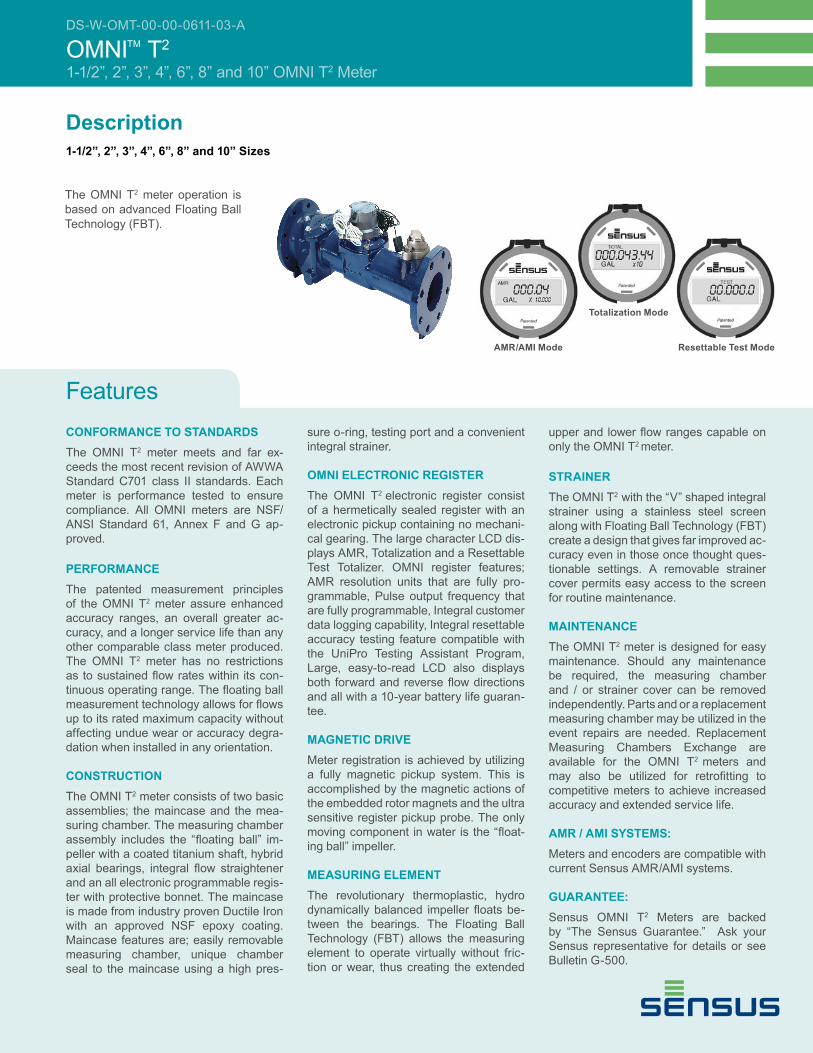
The OMNI T2 meter operation is
based on advanced Floating Ball
Technology (FBT).
DS-W-OMT-00-00-0611-03-A
OMNITM T2
1-1/2”, 2”, 3”, 4”, 6”, 8” and 10” OMNI T2 Meter
AMR/AMI Mode
Totalization Mode
Resettable Test Mode
DS-W-OMT-00-00-0611-03-A
Page 2 of 5
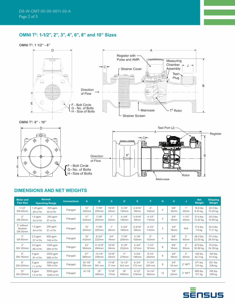
OMNI T2: 1-1/2”, 2”, 3”, 4”, 6”, 8” and 10” Sizes
DIMENSIONS AND NET WEIGHTS
Meter and
Pipe Size
Normal
Operating RangeConnections A B C D E F G H J
Net
Weight
Shipping
Weight
1-1/2”
DN 40mm
1.25 gpm
.28 m3/hr
200 gpm
45 m3/hrFlanged
13”
330mm
7-7/8”
200mm
15/16”
24mm
5-1/8”
130mm
2-5/16”
59mm
4”
102mm2
5/8”
16mm
1”
25mm
18.8 lbs.
8.53 kg..
22.5 lbs.
10.20 kg.
2”
DN 50mm
1.5 gpm
.34 m3/hr
250 gpm
57 m3/hrFlanged
17”
432mm
7-7/8”
200mm
1”
25mm
5-3/4”
146mm
2-5/16”
59mm
4-1/2”
114mm2
3/4”
19mm
1-1/2”
40mm
27.4 lbs.
12.42 kg.
34.5 lbs.
15.65 kg.
2” without
Strainer
DN 50mm
1.5 gpm
.34 m3/hr
250 gpm
57 m3/hrFlanged
10”
254mm
7-7/8”
200mm
1”
25mm
5-3/4”
146mm
2-5/16”
59mm
4-1/2”
114mm2
3/4”
19mmN/A
17.4 lbs.
7.9 kg.
24.5 lbs.
11.11 kg.
3”
DN 80mm
2.5 gpm
.57 m3/hr
650 gpm
148 m3/hrFlanged
19”
432mm
8-3/4”
222mm
3/4”
19mm
7-7/8”
200mm
4-1/8”
105mm
6”
153mm4
5/8”
16mm
2”
50mm
48.5 lbs.
22.00 kg.
57.4 lbs.
26.04 kg.
4”
DN 100mm
3.0 gpm
.68 m3/hr
1250 gpm
284 m3/hrFlanged
23”
584mm
11-3/16”
284mm
15/16”
24mm
9-1/8”
232mm
4-3/4”
121mm
7-1/2”
191mm8
5/8”
16mm
2”
50mm
67.9 lbs.
30.80 kg.
75.8 lbs.
34.38 kg.
6”
DN 150mm
4 gpm
.91 m3/hr
2500 gpm
568 m3/hrFlanged
27”
685mm
13-1/4”
336mm
15/16”
24mm
11”
279mm
5-3/4”
146mm
9-1/2”
242mm8
3/4”
19mm
2”
50mm
140 lbs.
52.3 kg.
165 lbs.
61.6 kg.
8”
DN 200mm
5 gpm
1.1 m3/hr
3500 gpm
795 m3/hrFlanged
30-1/8”
765 mm
15”
381 mm
11/16”
17 mm
13-1/2”
343 mm
6-3/4”
172 mm
11-3/4”
300 mm8
3/4”
19 mm2” NPT
471 lbs.
214 kg.
521 lbs.
236 kg.
10”
DN 250mm
6 gpm
1.4 m3/hr
5500 gpm
1249 m3/hrFlanged
41-1/8 19”
485mm
11/16”
17mm
16”
406mm
8-1/2”
216mm
14-1/4”
362mm12
7/8”
22mm2” NPT
685 lbs.
311 kg.
745 lbs.
338 kg.
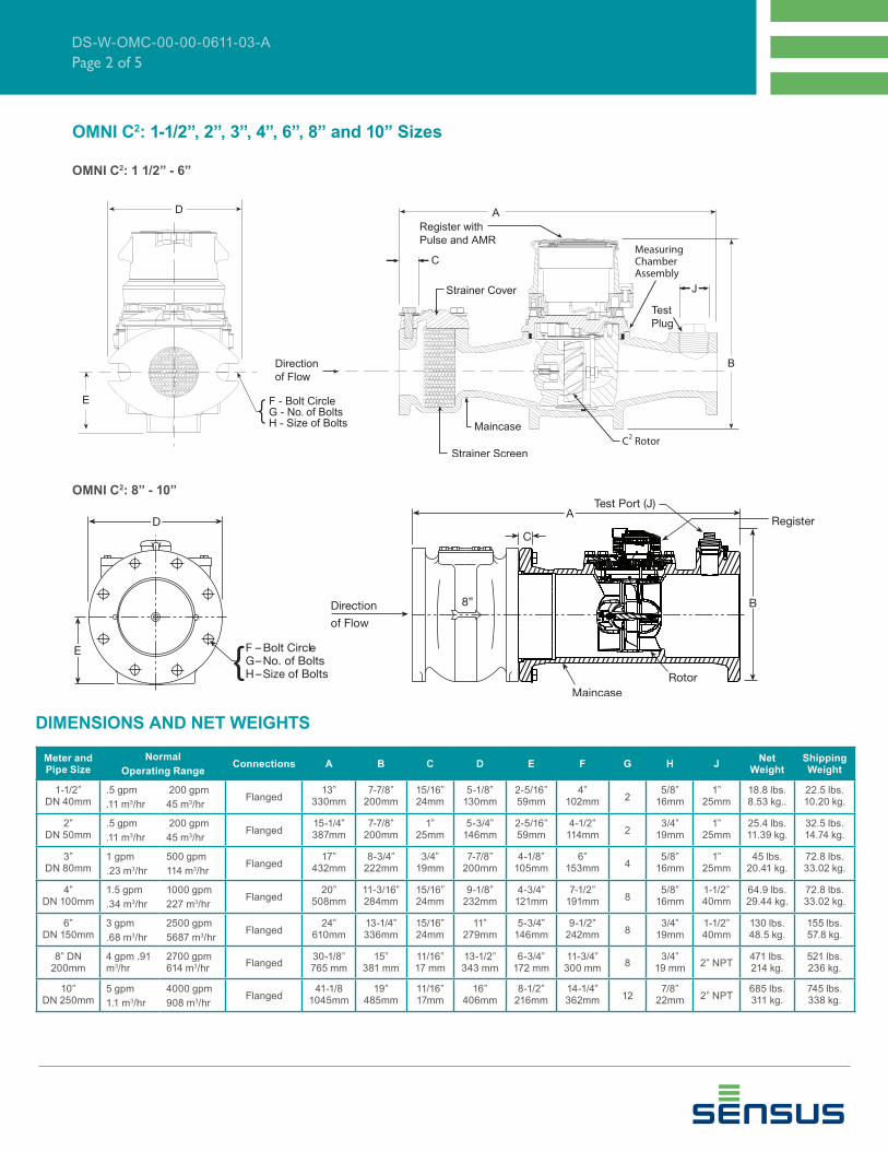
E
D
F - Bolt CircleG - No. of BoltsH - Size of Bolts{
C
A
B
J
Direction
of Flow
Strainer Screen
Maincase T2 Rotor
Strainer Cover
Register with
Pulse and AMR
Test
Plug
Measuring
Chamber
Assembly
OMNI T2: 8” - 10”
OMNI T2: 1 1/2” - 6”

DS-W-OMT-00-00-0611-03-A
Page 3 of 5
SERVICE Measurement of potable and reclaim water.
Operating temperature range of 33 oF (56 oC) - 150 oF (65.6 oC)
OPERATINGRANGE
(100% ± 1.5%)
1-1/2”: 1.25 – 200 GPM (.28 - 45 m3/hr)
2” and 2” without Strainer: 1.5 – 250 GPM (.34 – 57 m3/hr)
3”: 2.5 – 650 GPM (.57 – 148 m3/hr)
4”: 3 – 1250 GPM (.68 – 284 m3/hr)
6”: 4 – 2500 GPM (.91 – 568 m3/hr)
8”: 5 – 3500 GPM (1.1-795 m3/hr)
10”: 6 – 5500 GPM (1.4 - 1249 m3/hr)
LOW FLOW
(95% – 101.5%)
1-1/2”: .75 GPM (.17 m3/hr)
2” and 2” without Strainer: 1.0 GPM (.23 m3/hr)
3”: 1.5 GPM (.34 m3/hr)
4”: 2.0 GPM (.45 m3/hr)
6”: 2.5 GPM (.57 m3/hr)
8”: 4 GPM (0.9 m3/hr)
10”: 5 GPM (1.1 m3/hr)
MAXIMUMCONTINUOUS OPERATION
1-1/2”: 160 GPM (36 m3/hr)
2” and 2” without Strainer: 200 GPM (45 m3/hr)
3”: 500 GPM (114 m3/hr)
4”: 1000 GPM (227 m3/hr)
6”: 2000 GPM (454 m3/hr)
8”: 3500 GPM (795 m3/hr)
10”: 5500 GPM (1249 m3/hr)
MAXIMUMINTERMITTENT OPERATION
1-1/2”: 200 GPM (45 m3/hr)
2” and 2” without Strainer: 250 GPM (57 m3/hr)
3”: 650 GPM (148 m3/hr)
4”: 1250 GPM (284 m3/hr)
6”: 2500 GPM (568 m3/hr)
8”: 4700 GPM (1067 m3/hr)
10”: 7000 GPM (1590 m3/hr)
PRESSURE LOSS
1-1/2”: 6.9 psi @ 160 GPM (48 bar @ 36 m3/hr)
2” and 2” without Strainer: 7.0 psi @ 200 GPM (.48 bar @ 45 m3/hr)
3”: 5.1 psi @ 500 GPM (.35 bar @ 114 m3/hr)
4”: 8.7 psi @ 1000 GPM (.60 bar @ 227 m3/hr)
6”: 8.2 psi @ 2000 GPM (.56 bar @ 454 m3/hr)
8”: 5.1 psi @ 3500 GPM (.35 bar @ 795 m3/hr)
10”: 7.2 psi @ 5500 GPM (.50 bar @ 1249 m3/hr)
MAXIMUM OPERATING PRESSURE
200 PSI (13.8 bar)
FLANGE CONNECTIONS
U.S. ANSI B16.1 / AWWA Class 125
REGISTER Fully electronic sealed register with programmable registration (Gal. /Cu.Ft./ Cu. Mtr. / Imp.Gal / Acre Ft.)
Programmable AMR/AMI reading and pulse outputs
Guaranteed 10 year battery life
NSF
APPROVED MATERIALS
Maincase: Measuring Chamber: Rotor “Floating Ball”: Radial Bearings: Thrust Bearings: Magnets: Strainer Screen: Strainer Cover: Test Plug:
Coated Ductile IronThermoplastic ThermoplasticHybrid ThermoplasticSapphire/Ceramic Jewel Ceramic MagnetStainless SteelCoated Ductile IronCoated Ductile Iron
SPECIFICATIONS
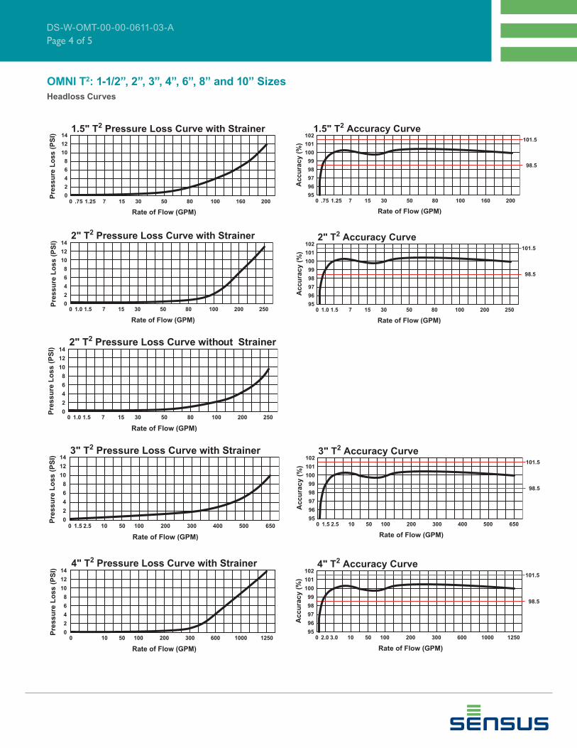
OMNI T2: 1-1/2”, 2”, 3”, 4”, 6”, 8” and 10” Sizes
DS-W-OMT-00-00-0611-03-A
Page 4 of 5
1.5" T 2 Pressure Loss Curve with Strainer
0 .75 1.25 7 1 5 3 0 5 0 8 0 100 160 200
Rate of Flow (GPM)
Pre
ss
ure
Lo
ss
(P
SI)
0
4
2
6
8
10
12
14
95
97
96
98
99
100
101
1021.5" T2 Accuracy Curve
0 .75 1.25 7 15 30 50 80 100 160 200
101.5
98.5
Rate of Flow (GPM)
Accu
racy (
%)
OMNI T2: 1-1/2”, 2”, 3”, 4”, 6”, 8” and 10” Sizes
Headloss Curves
2" T 2 Pressure Loss Curve with Strainer
0 1.0 1.5 7 1 5 3 0 5 0 8 0 100 200 250
Rate of Flow (GPM)
0
4
2
6
8
10
12
14
Pre
ss
ure
Lo
ss
(P
SI)
95
97
96
98
99
100
101
1022" T2 Accuracy Curve
0 1.0 1.5 7 15 30 50 80 100 200 250
101.5
98.5
Rate of Flow (GPM)
Ac
cu
rac
y (
%)
95
97
96
98
99
100
101
1023" T2 Accuracy Curve
0 1.5 2.5 10 50 100 200 300 400 500 650
101.5
98.5
Rate of Flow (GPM)
Accu
racy (
%)
4" T 2 Pressure Loss Curve with Strainer
0 1 0 5 0 100 200 300 600 1000 1250
Rate of Flow (GPM)
0
4
2
6
8
10
12
14
Pre
ss
ure
Lo
ss
(P
SI)
95
97
96
98
99
100
101
1024" T2 Accuracy Curve
0 2.0 3.0 10 50 100 200 300 600 1000 1250
101.5
98.5
Rate of Flow (GPM)
Ac
cu
rac
y (
%)

8601 Six Forks Road, Suite 700
Raleigh, NC 27615
1-800-638-3748
www.sensus.com/water
© All products purchased and services performed are subject to Sensus’ terms of sale, available at either; http://na.sensus.com/TC/TermsConditions.pdf or 1-800-METER-IT. Sensus reserves the right to modify
these terms and conditions in its own discretion without notice to the customer.
This document is for informational purposes only, and SENSUS MAKES NO EXPRESS WARRANTIES IN THIS DOCUMENT. FURTHERMORE, THERE ARE NO IMPLIED WARRANTIES, INCLUDING
WITHOUT LIMITATION, WARRANTIES AS TO FITNESS FOR A PARTICULAR PURPOSE AND MERCHANTABILITY. ANY USE OF THE PRODUCTS THAT IS NOT SPECIFICALLY PERMITTED HEREIN
IS PROHIBITED.
DS-W-OMT-00-00-0611-03-A
Page 5 of 5
6" T 2 Pressure Loss Curve with Strainer
0 2 5 5 0 100 500 1000 1500 2000 2500
Rate of Flow (GPM)
0
4
2
6
8
10
12
14
Pre
ss
ure
Lo
ss
(P
SI)
95
97
96
98
99
100
101
1026" T2 Accuracy Curve
0 2.5 4.0 25 50 100 500 1000 1500 2000 2500
101.5
98.5
Rate of Flow (GPM)
Ac
cu
rac
y (
%)
OMNI T2: 1-1/2”, 2”, 3”, 4”, 6”, 8” and 10” Sizes
Headloss Curves
CONFORMANCE TO STANDARDS
The OMNI C2 meter meets and far
exceeds the most recent revision of
AWWA Standard C701 and C702 class
II. Additionally, the meter does not require
a valve to meet these standards. Each
meter is performance tested to ensure
compliance. All OMNI meters are NSF/
ANSI Standard 61, Annex F and G
approved latest standards.
PERFORMANCE
The patented measurement principles
of the OMNI C2 meter assure enhanced
accuracy ranges, an overall greater
accuracy, and a longer service life
than any other comparable class meter
produced. The OMNI C2 meter has no
restrictions as to sustained fl ow rates
within its continuous operating range. The
fl oating ball measurement technology
allows for fl ows up to its rated maximum
capacity without undue wear or accuracy
degradation when installed in any
orientation.
CONSTRUCTION
The OMNI C2 meter consists of two
basic assemblies; the maincase and
the measuring chamber. The measuring
chamber assembly includes the “fl oating
ball” impeller with a coated titanium
shaft, hybrid axial bearings, integral
fl ow straightener and an all electronic
programmable register with protective
bonnet. The maincase is made from
industry proven Ductile Iron with an
approved NSF epoxy coating. Maincase
features are; easily removable measuring
chamber, unique chamber seal to the
maincase using a high pressure o-ring,
testing port and an AWWA compliant
strainer.
OMNI ELECTRONIC REGISTER
The OMNI C2 electronic register is
hermetically sealed with an electronic
pickup containing no mechanical gearing.
The large character LCD displays
AMR, Totalization and a Resettable
Test Totalizer. OMNI register features;
AMR resolution units that are fully
programmable, Pulse output frequency
that are fully programmable, Integral
customer data logging capability, Integral
resettable accuracy testing feature
compatible with UniPro Testing Assistant
Program, Large, easy-to-read LCD also
displays both forward and reverse fl ow
directions and all with a 10-year battery
life guarantee.
MAGNETIC DRIVE
Meter registration is achieved by utilizing
a fully magnetic pickup system. This is
accomplished by the magnetic actions
of the embedded rotor magnets and the
ultra sensitive register pickup probe. The
only moving component in water is the
“fl oating ball” impeller.
MEASURING ELEMENT
The revolutionary thermoplastic, hydro-
dynamically balanced impeller fl oats
between the bearings. The Floating Ball
Technology (FBT) allows the measuring
element to operate virtually without fric-
tion or wear, thus creating the extended
upper and lower fl ow ranges capable on
only the OMNI C2 meter.
STRAINER
The OMNI C2 with the AWWA compliant
“V” shaped strainer using a stainless
steel screen along with Floating Ball
Technology (FBT) create a design that
gives far improved accuracy even in
those once thought questionable settings.
A removable strainer cover permits
easy access to the screen for routine
maintenance.
MAINTENANCE
The OMNI C2 meter is designed for easy
maintenance. Should any maintenance
be required, the measuring chamber
and / or strainer cover can be removed
independently. Parts and or a replacement
measuring chamber may be utilized in the
event repairs are needed. Replacement
Measuring Chambers are available for
the OMNI C2 meters and may also be
utilized for retrofi tting to competitive
meters to achieve increased accuracy
and extended service life.
AMR / AMI SYSTEMS:
Meters and encoders are compatible with
current Sensus AMR/AMI systems.
GUARANTEE:
Sensus OMNI C2 Meters are backed
by “The Sensus Guarantee.” Ask your
Sensus representative for details or see
Bulletin G-500.
Features
Description
1-1/2”, 2”, 3”, 4”, 6”, 8” and 10” Sizes
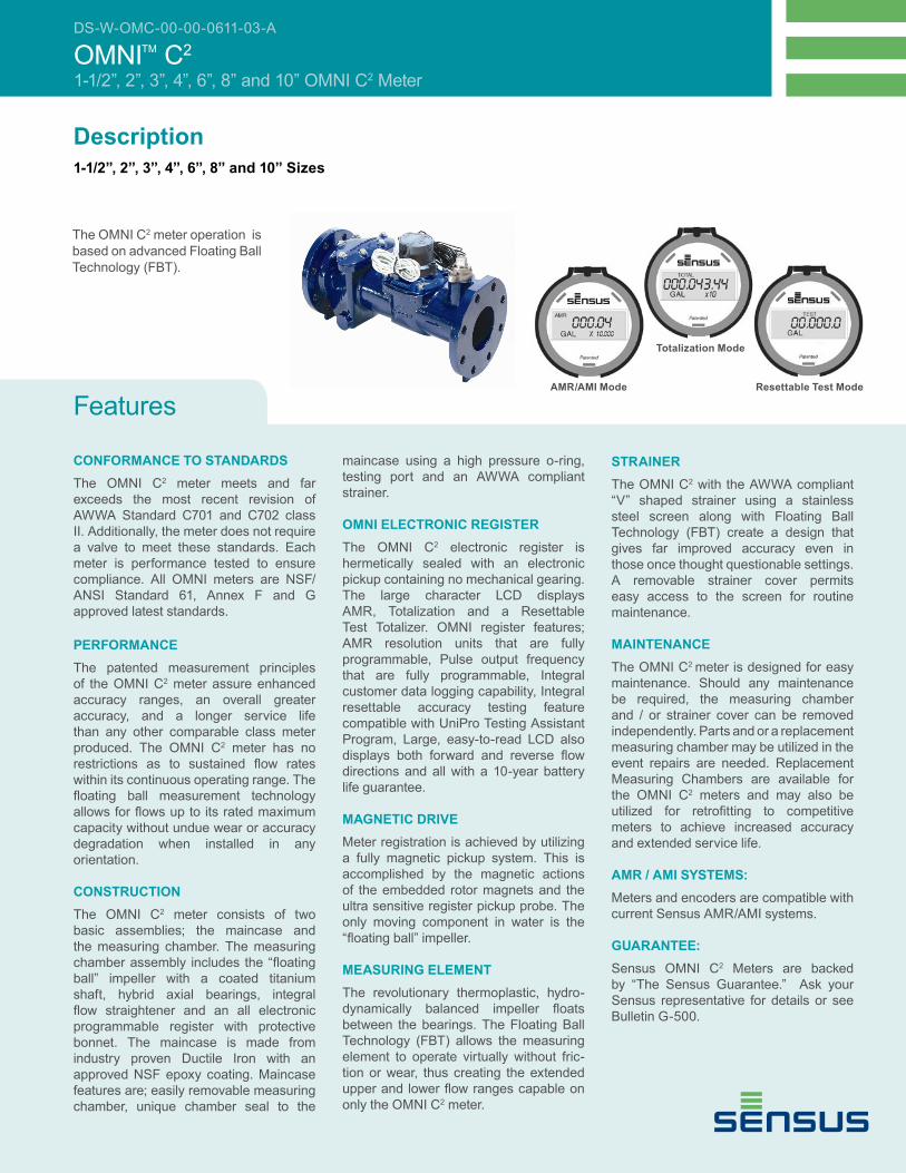
The OMNI C2 meter operation is
based on advanced Floating Ball
Technology (FBT).
DS-W-OMC-00-00-0611-03-A
OMNITM C2
1-1/2”, 2”, 3”, 4”, 6”, 8” and 10” OMNI C2 Meter
AMR/AMI Mode
Totalization Mode
Resettable Test Mode
DS-W-OMC-00-00-0611-03-A
Page 2 of 5
OMNI C2: 1-1/2”, 2”, 3”, 4”, 6”, 8” and 10” Sizes
DIMENSIONS AND NET WEIGHTS
Meter and Pipe Size
Normal
Operating RangeConnections A B C D E F G H J
Net Weight
Shipping Weight
1-1/2” DN 40mm
.5 gpm
.11 m3/hr
200 gpm
45 m3/hrFlanged
13” 330mm
7-7/8” 200mm
15/16” 24mm
5-1/8” 130mm
2-5/16” 59mm
4” 102mm 2
5/8” 16mm
1” 25mm
18.8 lbs. 8.53 kg..
22.5 lbs. 10.20 kg.
2” DN 50mm
.5 gpm
.11 m3/hr
200 gpm
45 m3/hrFlanged
15-1/4” 387mm
7-7/8” 200mm
1” 25mm
5-3/4” 146mm
2-5/16” 59mm
4-1/2” 114mm 2
3/4” 19mm
1” 25mm
25.4 lbs. 11.39 kg.
32.5 lbs. 14.74 kg.
3” DN 80mm
1 gpm
.23 m3/hr
500 gpm
114 m3/hrFlanged
17” 432mm
8-3/4” 222mm
3/4” 19mm
7-7/8” 200mm
4-1/8” 105mm
6” 153mm 4
5/8” 16mm
1” 25mm
45 lbs. 20.41 kg.
72.8 lbs. 33.02 kg.
4” DN 100mm
1.5 gpm
.34 m3/hr
1000 gpm
227 m3/hrFlanged
20” 508mm
11-3/16” 284mm
15/16” 24mm
9-1/8” 232mm
4-3/4” 121mm
7-1/2” 191mm 8
5/8” 16mm
1-1/2” 40mm
64.9 lbs. 29.44 kg.
72.8 lbs. 33.02 kg.
6” DN 150mm
3 gpm
.68 m3/hr
2500 gpm
5687 m3/hrFlanged
24” 610mm
13-1/4” 336mm
15/16” 24mm
11” 279mm
5-3/4” 146mm
9-1/2” 242mm 8
3/4” 19mm
1-1/2” 40mm
130 lbs. 48.5 kg.
155 lbs. 57.8 kg.
8” DN 200mm
4 gpm .91 m3/hr
2700 gpm 614 m3/hr
Flanged30-1/8” 765 mm
15” 381 mm
11/16” 17 mm
13-1/2” 343 mm
6-3/4” 172 mm
11-3/4” 300 mm
83/4”
19 mm2” NPT
471 lbs. 214 kg.
521 lbs. 236 kg.
10” DN 250mm
5 gpm
1.1 m3/hr
4000 gpm
908 m3/hrFlanged
41-1/81045mm
19” 485mm
11/16” 17mm
16” 406mm
8-1/2” 216mm
14-1/4” 362mm 12
7/8” 22mm 2” NPT
685 lbs. 311 kg.
745 lbs. 338 kg.
OMNI C2: 1 1/2” - 6”
OMNI C2: 8” - 10”

DS-W-OMC-00-00-0611-03-A
Page 3 of 5
SERVICE Measurement of potable and reclaim water.
Operating temperature range of 33 oF (56 oC) - 150 oF (65.6 oC)
OPERATINGRANGE(100% ± 1.5%)
1-1/2”: .5 – 200 GPM (.11 - 45 m3/hr)
2”: .5 – 200 GPM (.11 - 45 m3/hr)
3”: 1.0 – 500 GPM (.23 - 114 m3/hr)
4”: 1.5 – 1000 GPM (.34 - 227 m3/hr)
6”: 3 – 2000 GPM (.68 - 454 m3/hr)
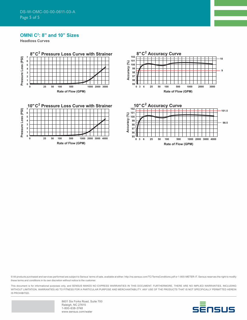
8”: 4 – 2700 GPM (0.91 – 614 m3/hr)
10”: 5-4000 GPM (1.1-908 m3/hr)
LOW FLOW
(95% – 101.5%)
1-1/2”: .25 GPM (.06 m3/hr)
2”: .25 GPM (.06 m3/hr)
3”: .5 GPM (.11 m3/hr)
4”: .75 GPM (.17 m3/hr)
6”: 1.5 GPM (.34 m3/hr)
8”: 2.5 GPM (0.57 m3/hr)
10”: 3.5 GPM (0.8 m3/hr)
MAXIMUMCONTINUOUS OPERATION
1-1/2”: 160 GPM (36m3/hr)
2”: 160 GPM (36 m3/hr)
3”: 400 GPM (91 m3/hr)
4”: 800 GPM (182 m3/hr)
6”: 1600 GPM (363 m3/hr)
8”: 2700 GPM (614 m3/hr)
10”: 4000 GPM (908 m3/hr)
MAXIMUMINTERMITTENT OPERATION
1-1/2”: 200 GPM (45 m3/hr)
2”: 200 GPM (45 m3/hr)
3”: 500 GPM (114 m3/hr)
4”: 1000 GPM (227 m3/hr)
6”: 2000 GPM (454 m3/hr)
8”: 3400 GPM (773 m3/hr)
10”: 5000 GPM (1136 m3/hr)
PRESSURE LOSS 1-1/2”: 6.9 psi @ 160 GPM (48 bar @ 36 m3/hr)
2”: 4.3 psi @ 160 GPM (.30 bar @ 36 m3/hr)
3”: 3.2 psi @ 400 GPM (.22 bar @ 91 m3/hr)
4”: 6.4 psi @ 800 GPM (.51 bar @ 182 m3/hr)
6”: 5.5 psi @ 1600 GPM (.56 bar @ 363 m3/hr)
8”: 4 psi @ 2700 GPM (.27 bar @ 614 m3/hr)
10”: 4.5 psi @ 4000 GPM (.31 bar @ 908 m3/hr)
MAXIMUM OPERATING PRESSURE
200 PSI (13.8 bar)
FLANGE CONNECTIONS
U.S. ANSI B16.1 / AWWA Class 125
REGISTER Fully electronic sealed register with programmable registration (Gal. /Cu.Ft./ Cu. Mtr. / Imp.Gal / Acre Ft.)
Programmable AMR/AMI reading and pulse outputs
Guaranteed 10 year battery life
NSF
APPROVED
MATERIALS
Maincase: Measuring Chamber: Rotor “Floating Ball”: Radial Bearings: Thrust Bearings: Magnets: Strainer Screen: Strainer Cover: Test Plug:
Coated Ductile IronThermoplastic ThermoplasticHybrid ThermoplasticSapphire/Ceramic Jewel Ceramic MagnetStainless SteelCoated Ductile IronCoated Ductile Iron
SPECIFICATIONS
OMNI C2: 1-1/2”, 2”, 3”, 4”, 6”, 8” and 10” Sizes

DS-W-OMC-00-00-0611-03-A
Page 4 of 5
1.5" C 2 Pressure Loss Curve with Strainer
0 .25 1 7 1 5 3 0 5 0 8 0 100 160 200
Rate of Flow (GPM)
Pre
ss
ure
Lo
ss
(P
SI)
0
4
2
6
8
10
12
14
95
97
96
98
99
100
101
1021.5" C2 Accuracy Curve
0 .25 1 7 15 30 50 80 100 160 200
101.5
98.5
Rate of Flow (GPM)
Accu
racy (
%)
OMNI C2: 1-1/2”, 2”, 3”, 4”, and 6” Sizes
Headloss Curves
2" C 2 Pressure Loss Curve with Strainer
0 1.0 1.5 7 1 5 3 0 5 0 8 0 100 200 250
Rate of Flow (GPM)
0
4
2
6
8
10
12
14
Pre
ss
ure
Lo
ss
(P
SI)
95
97
96
98
99
100
101
1022" C2 Accuracy Curve
0 .25 1 7 15 30 50 80 100 160 200
101.5
98.5
Rate of Flow (GPM)
Ac
cu
rac
y (
%)
3" C 2 Pressure Loss Curve with Strainer
0 1.5 2.5 10 50 100 200 300 400 500 650
Rate of Flow (GPM)
Pre
ss
ure
Lo
ss
(P
SI)
0
4
2
6
8
10
12
14
95
97
96
98
99
100
101
1023" C2 Accuracy Curve
0 .5 1.0 10 50 100 200 300 400 500 650
101.5
98.5
Rate of Flow (GPM)
Accu
racy (
%)
4" C 2 Pressure Loss Curve with Strainer
0 1 0 5 0 100 200 300 600 1000 1250
Rate of Flow (GPM)
0
4
2
6
8
10
12
14
Pre
ss
ure
Lo
ss
(P
SI)
95
97
96
98
99
100
101
1024" C2 Accuracy Curve
0 1 1.5 10 50 100 200 300 600 1000 1250
101.5
98.5
Rate of Flow (GPM)
Ac
cu
rac
y (
%)
6" C 2 Pressure Loss Curve with Strainer
0 2 5 5 0 100 500 1000 1500 2000 2500
Rate of Flow (GPM)
0
4
2
6
8
10
12
14
Pre
ss
ure
Lo
ss
(P
SI)
95
97
96
98
99
100
101
1026" C2 Accuracy Curve
0 1.5 3.0 25 50 100 500 1000 1500 2000 2500
101.5
98.5
Rate of Flow (GPM)
Accu
racy (
%)
8601 Six Forks Road, Suite 700
Raleigh, NC 27615
1-800-638-3748
www.sensus.com/water
© All products purchased and services performed are subject to Sensus’ terms of sale, available at either; http://na.sensus.com/TC/TermsConditions.pdf or 1-800-METER-IT. Sensus reserves the right to modify
these terms and conditions in its own discretion without notice to the customer.
This document is for informational purposes only, and SENSUS MAKES NO EXPRESS WARRANTIES IN THIS DOCUMENT. FURTHERMORE, THERE ARE NO IMPLIED WARRANTIES, INCLUDING
WITHOUT LIMITATION, WARRANTIES AS TO FITNESS FOR A PARTICULAR PURPOSE AND MERCHANTABILITY. ANY USE OF THE PRODUCTS THAT IS NOT SPECIFICALLY PERMITTED HEREIN
IS PROHIBITED.
DS-W-OMC-00-00-0611-03-A
Page 5 of 5
OMNI C2: 8” and 10” SizesHeadloss Curves

CONFORMANCE TO STANDARDS
The OMNI F2 meter meets and far exceeds
the most recent revision of AWWA
Standard C703 class II. Additionally,
the meter does not require a valve to
meet these standards. Each meter is
performance tested to ensure compliance.
All OMNI meters are NSF/ANSI Standard
61, Annex F and G approved. The OMNI
F2 meter is UL (Underwriters Laboratories)
Listed and FM (Factory Mutual) approved
for use on fi re protection and domestic
water applications.
PERFORMANCE
The patented measurement principles of
the OMNI F2 meter assure enhanced ac-
curacy ranges, an overall greater accura-
cy, and a longer service life than any other
comparable class meter produced. The F2
meter has no restrictions as to sustained
fl ow rates within its continuous operat-
ing range. The fl oating ball measurement
technology allows for fl ows up to its rated
maximum capacity without undue wear or
accuracy degradation.
CONSTRUCTION
The OMNI F2 meter consists of two basic
assemblies; the maincase and the mea-
suring chamber. The measuring chamber
assembly includes the “fl oating ball” im-
peller with a coated titanium shaft, hybrid
axial bearings, integral fl ow straightener
and an all electronic programmable regis-
ter with protective bonnet. The maincase
is made from industry proven Ductile Iron
with an approved NSF epoxy coating.
Maincase features are; easily removable
measuring chamber, unique chamber
seal to the maincase using a high pres-
sure o-ring, testing port and a convenient
integral strainer with optional drain/debris-
fl ushing ports.
OMNI ELECTRONIC REGISTER
The OMNI F2 electronic register is her-
metically sealed with electronic pickup
containing no mechanical gearing. The
large character LCD displays AMR, To-
talization and a Resettable Test Totalizer.
OMNI register features; AMR resolution
units that are fully programmable, Pulse
output frequency that are fully program-
mable, Integral customer data logging
capability, Integral resettable accuracy
testing feature compatible with the UniPro
Testing Assistant Program, Large, easy-
to-read LCD also displays both forward
and reverse fl ow directions and all with a
10-year battery life guarantee.
MAGNETIC DRIVE
Meter registration is achieved by utilizing
a fully magnetic pickup system. This is
accomplished by the magnetic actions of
the embedded rotor magnets and the ultra
sensitive register pickup probe. The only
moving component in water is the “fl oat-
ing ball” impeller.
MEASURING ELEMENT
The revolutionary thermoplastic, hydro
dynamically balanced impeller fl oats be-
tween the bearings. The Floating Ball
Technology (FBT) allows the measuring
element to operate virtually without fric-
tion or wear, thus creating the extended
upper and lower fl ow ranges capable on
only the OMNI F2 meter.
STRAINER
The OMNI F2 meter includes the Sensus
designed “V” shaped UL Listed/FM ap-
proved strainer which utilizes a stainless
steel screen along with Floating Ball Tech-
nology (FBT) to create a design that gives
far improved accuracy even in those once
thought questionable settings. A remov-
able strainer cover permits easy access
to the screen for routine maintenance.
Optional drain ports, located at the back
lower corners of the strainer body, allow
for easy discharging of debris without the
need to remove the cover.
MAINTENANCE
The OMNI F2 meter is designed for easy
maintenance. Should any maintenance
be required, the measuring chamber and/
or strainer cover can be removed inde-
pendently. Parts and or a replacement
measuring chamber may be utilized in the
event repairs are needed. Replacement
Measuring Chambers are available for the
OMNI F2 meters.
AMR / AMI SYSTEMS
Meters and encoders are compatible with
current Sensus AMR/AMI systems.
GUARANTEE
Sensus OMNI F2 Meters are backed
by “The Sensus Guarantee.” Ask your
Sensus representative for details or see
Bulletin G-500.
Features
Description
4”, 6”, 8” and 10” Sizes
The OMNI F2 meter operation is
based on advanced Floating Ball
Technology (FBT).
DS-W-OMF-00-00-0611-02-A
OMNITM F2
4”, 6”, 8” and 10” OMNI F2 Meter
AMR/AMI Mode
Totalization Mode
Resettable Test Mode

DS-W-OMF-00-00-0611-02-A
Page 2 of 3
SPECIFICATIONS
DIMENSIONS AND NET WEIGHTS
Meter and
Pipe Size
Normal
Operating RangeConnections A B C D E F G H J
Net
Weight
Shipping
Weight
Standard
Fireline
4”
DN 100mm
1.5 gpm
.34 m3/hr
1000 gpm
227 m3/hrFlanged
33”
838mm
13-11/16”
348mm
15/16”
24mm
17-1/2”
446mm
4-3/4”
121mm
7-1/2”
191mm8
5/8”
16mm
2”
50mm
212 lbs.
96 kg.
252 lbs.
115 kg.
51-7/8”
(1317mm)
6”
DN 150mm
3.0 gpm
.681 m3/hr
2000 gpm
454 m3/hrFlanged
45”
1143mm
15-3/4”
400mm
15/16”
24mm
22-3/8”
569mm
5-3/4”
146mm
9-1/2”
242mm8
3/4”
19mm
2”
50mm
394 lbs.
179 kg.
449 lbs.
204 kg.
67-5/8”
(1717mm)
8”
DN 200mm
4 gpm
.91 m3/hr
3500 gpm
795 m3/hrFlanged
53”
1346mm
18-1/2”
470mm
11/16”
17mm
31”
787mm
6-3/4”
172mm
11-3/4”
298mm8
3/4”
19mm
2”
NPT
736 lbs.
334 kg.
786 lbs.
357 kg.
77”
(1956mm)
10”
DN 250mm
5 gpm
1.1 m3/hr
5500 gpm
1249 m3/hrFlanged
68”
1727mm
22-1/4”
565mm
11/16”
17mm
37-1/3”
947mm
8-1/2”
216mm
14-1/4”
362mm 127/8
22mm
2”
NPT
1155 lbs.
524 kg.
1215 lbs.
551 kg.
90”
(2286mm)
1 Standard Fireline lay length with optional spool piece added.
E
D
F - Bolt CircleG - No. of BoltsH - Size of Bolts{
C
A
BDirection
of Flow
Strainer ScreenMaincase
F2
Rotor
Strainer Cover
Register with
Pulse and AMR
Test
Plug
Measuring
Chamber
Assembly
J
OMNI F2: 4”, 6”, 8” and 10”
SERVICE Measurement of potable and reclaim water.
Operating temperature range of 33 oF (56 oC) - 150 oF (65.6 oC)
OPERATING
RANGE
(100% ± 1.5%)
4”: 1.5 – 1000 GPM (.34 - 227 m3/hr)
6”: 3.0 – 2000 GPM (.34 - 227 m3/hr)
8”: 4– 3500 GPM (0.91-795 m3/hr)
10”: 5– 5500 GPM (1.1-1249 m3/hr)
LOW FLOW
(95% – 101.5%)
4”: .75 GPM (.06 m3/hr)6”: 1.5 GPM (.06 m3/hr)8”: 2.5 GPM (0.57 m3/hr)
10”: 3.5 GPM (0.8 m3/hr)
UL MINIMUM
FLOW
8”: 97% @ 3 GPM (0.68 m3/hr)
10”: 97% @ 4 GPM (0.9 m3/hr)
MAXIMUM
CONTINUOUS
OPERATION
4”: 1000 GPM (227 m3/hr)
6”: 2000 GPM (454 m3/hr)
8”: 3500 GPM (795 m3/hr)
10”: 5500 GPM (1249 m3/hr)
MAXIMUM
INTERMITTENT
OPERATION
4”: 1250 GPM (284 m3/hr)
6”: 2500 GPM (568 m3/hr)
8”: 4700 GPM (1067 m3/hr)
10”: 7000 GPM (1590 m3/hr)
PRESSURE
LOSS
4”: 6.4 psi @ 1000 GPM (.60 bar @ 227 m3/hr)
6”: 6.7 psi @ 2000 GPM (.56 bar @ 454 m3/hr)
8”: 5 psi @ 3500 GPM (.34 bar @ 795 m3/hr)
10”: 7 psi @ 5500 GPM (.48 bar @ 1249 m3/hr)
MAXIMUM
OPERATING
PRESSURE
175 PSI (12 bar)
FLANGE
CONNECTIONSU.S. ANSI B16.1 / AWWA Class 125
REGISTER Fully electronic sealed register with programmable registration (Gal. /Cu.Ft./ Cu. Mtr. / Imp.Gal / Acre Ft.)
Programmable AMR/AMI reading and pulse outputs
Guaranteed 10 year battery life
NSF
APPROVED
MATERIALS
Maincase:
Measuring Chamber:
Rotor “Floating Ball”:
Radial Bearings:
Thrust Bearings:
Magnets:
Strainer Screen:
Strainer Cover:
Test Plug:
Coated Ductile Iron
Thermoplastic
Thermoplastic
Hybrid Thermoplastic
Sapphire/Ceramic Jewel
Ceramic Magnet
Stainless Steel
Coated Ductile Iron
Coated Ductile Iron

8601 Six Forks Road, Suite 700
Raleigh, NC 27615
1-800-638-3748
www.sensus.com/water
© All products purchased and services performed are subject to Sensus’ terms of sale, available at either; http://na.sensus.com/TC/TermsConditions.pdf or 1-800-METER-IT. Sensus reserves the right to modify
these terms and conditions in its own discretion without notice to the customer.
This document is for informational purposes only, and SENSUS MAKES NO EXPRESS WARRANTIES IN THIS DOCUMENT. FURTHERMORE, THERE ARE NO IMPLIED WARRANTIES, INCLUDING
WITHOUT LIMITATION, WARRANTIES AS TO FITNESS FOR A PARTICULAR PURPOSE AND MERCHANTABILITY. ANY USE OF THE PRODUCTS THAT IS NOT SPECIFICALLY PERMITTED HEREIN
IS PROHIBITED.
DS-W-OMF-00-00-0611-02-A
Page 3 of 3
OMNI F2: 4”, 6”, 8” and 10”
Headloss Curves
4" F2 Pressure Loss Curve with Strainer
0 1 0 5 0 100 200 300 600 1000
Rate of Flow (GPM)
0
4
2
6
8
10
12
14
Pre
ss
ure
Lo
ss
(P
SI)
95
97
96
98
99
100
101
102 4" F2 Accuracy Curve
0 .5 1.5 10 50 100 200 300 600 1000
101.5
98.5
Rate of Flow (GPM)
Ac
cu
rac
y (
%)
6" F 2 Pressure Loss Curve with Strainer
0 2 5 5 0 100 500 1000 1500 2000 2500
Rate of Flow (GPM)
0
4
2
6
8
10
12
14
Pre
ss
ure
Lo
ss
(P
SI)
95
97
96
98
99
100
101
102 6" F 2 Accuracy Curve
0 1 3.0 25 50 100 500 1000 1500 2000 2500
101.5
98.5
Rate of Flow (GPM)
Ac
cu
rac
y (
%)
8" F 2 Pressure Loss Curve with Strainer
0 2 5 5 0 100 500 1000 2000 3500 2500
Rate of Flow (GPM)
0
2
1
3
4
6
8
10
Pre
ss
ure
Lo
ss
(P
SI)
95
97
96
98
99
100
101
102 8" F 2 Accuracy Curve
0 3 6 25 50 100 500 1000 2000 3500 2500
101.5
98.5
Rate of Flow (GPM)
Ac
cu
rac
y (
%)
10" F 2 Pressure Loss Curve with Strainer
0 2 5 5 0 100 500 1000 2500 5500 2500
Rate of Flow (GPM)
0
3
1
5
6
8
10
12
Pre
ss
ure
Lo
ss
(P
SI)
450095
97
96
98
99
100
101
102 10" F 2 Accuracy Curve
0 3 6 25 50 100 500 1000 2500 5500 2500
101.5
98.5
Rate of Flow (GPM)
Ac
cu
rac
y (
%)
4500