Embed Size (px)
Citation preview

UNIT 3COMMON
PLUMBINGPROCESSES
Summary
In this unit, we cover the following:
• Using hand tools • Cutting• Using power tools • Bending• Measuring • Jointing and• Marking out • Fixing
on a range of pipework materials, copper, low carbon steel (LCS) and plas-tic, used in domestic plumbing systems.
In addition to the items mentioned above, we also look at:
• Generic systems knowledge• Associated trade skills, such as:
– Processes for lifting flooring surfaces– Requirements for cutting holes and notching timber joists– Procedures for cutting holes through a range of materials– Making good.
One key feature about this unit is that we ask you to carry out some of yourown research. As a plumber, finding information out for yourself is a use-ful skill to learn because you need to keep up-to-date with changes toregulations and new technology. It is also necessary in this unit because itwould have been impossible for us to include every type of fitting or fixingthat is available.
Ch03-H8434.qxd 4/11/07 5:41 PM Page 81
Introduction
The purpose of this unit is to cover what we refer to as genericsystems knowledge, these are areas that are ‘general’ or commonto all the systems used in the domestic plumbing and heatingindustry and it will save repeating the same information duringeach systems unit: cold water, hot water, etc.
Generic systems knowledge covers topics such as taking basic sitemeasurements, how to prepare work locations, use of specifica-tions, paperwork for ordering materials, and how to deal withcustomers and co-workers.
We think it is important that you understand the preparation workthat is required before starting a job – that is why we have put thisunit first.
Use of documentationGeneral documentation can include such things as:
● Health and Safety Regulations, covered earlier in the Healthand Safety Unit
● Water Regulations● Requirements of British Standard Specifications and in
particular BS 6700 and BS 8000● Building Regulations, affecting a plumber’s work such as
the energy efficiency of central heating boilers.
The above documents underpin much of the work that is carried outby the plumber. Other documentation includes manufacturers’instructions, site drawings, job specifications and work programmes.
Manufacturers’ instructions
Most appliances and plumbing components are supplied withmanufacturers’ instructions. These provide information on theinstallation service and maintenance requirements and once anappliance is installed, these instructions should be left with thecustomer for future reference. Depending on the type of applianceor component, user instructions are also included.
Site drawings
Site drawings are covered in greater detail at Level 3. Building draw-ings provide details of how a building is going to be designed, e.g.size and shape of rooms, location of doors and windows, etc. They
82 Plumbing
UN
IT 3
Generic systemsknowledge
Key point
Domestic plumbing can varyfrom carrying out a smallmaintenance job like re-washering a tap, to carryingout complete systeminstallations on large scale newhousing developments. In thisbook, we make reference to‘larger contracts’ and we takethis to mean the large scalenew housing developments orrefurbishments where sitedrawings, specifications andwork programmes are likely tobe used.
Ch03-H8434.qxd 4/11/07 5:41 PM Page 82
also show specific design details, such as floor, wall and roof con-struction. Building services drawings show the layout of pipeworksystems and the location of appliances and components, such asbaths, sinks, water closets (WCs), radiators, boilers and pumps.
Job specifications
These usually accompany site and services drawings and details,and are mostly used on larger contracts.
83Common plumbing processes
UN
IT 3
Hot tips
Throughout this book, weencourage the reader toresearch the internet formanufacturers’ information aswell as provide contact detailsfor manufacturers’ catalogues.Try to get into the habit ofobtaining and reading theinformation as this will help tomake sure you keep yourselfup-to-date with new productsand technology.
Key point
If for any reason, a part of thejob cannot be done to thespecification, you should informyour supervisor, foreman oremployer immediately. Thisapplies equally to a smaller job,e.g. boiler replacement, where a detailed specification has notbeen provided but a quote orestimate has been provided,but the job, for whateverreason, can no longer be doneas originally planned.
Activity 3.1
What sort of details do you think a job specification mightcover? Jot down your thoughts for inclusion in your portfolioand check out your answers at the end of this book.
Specifications form part of the contract documentation, soany alterations required to the specification should not bedone by you.
Work programmes
If a plumber was working on a replacement bathroom suite, it isunlikely that a written work programme would have been pre-pared, but the plumber would have the work programme insidetheir head, based on an agreed start and finish date and a series ofactivities required in between to get the job done.
This principle is not very different on a larger contract but in thiscase, a contract programme will have been written out. This couldconsist of an overall programme for all site trades, as well as aseparate programme for each trade (Figure 3.1).
Other documentation
Other documentation used by plumbers relates to carrying out aplumbing job from an initial customer enquiry to completing thework. Let us take a look at the procedures for a typical job, addingthree extra radiators to an existing heating system, replacing theboiler and upgrading the controls.
● Customer asks a plumber for a quote● Plumber visits the customer, measures up and estimates the
materials required
Ch03-H8434.qxd 4/11/07 5:41 PM Page 83

● Plumber contacts the merchants and gets a quotation for thematerials
● This enables the plumber to finalise a quote to the customer● In our case, the customer accepts and the quotation is
confirmed in writing● The plumber orders the material from the merchants; on
delivery of materials, the plumber receives a delivery note● The work is carried out to meet the customer requirements● The plumber receives the invoice requesting payment for
the materials used, and accordingly invoices the customerfor the work that has been completed
● A remittance advice (record of payment) is sometimesissued with payment
● On any job, large or small, if you are advised that the deliv-ery of materials will be delayed or a particular item is notthe one ordered, either the site foreman (so he/she is awareof potential delays) or the immediate supervisor/employer isnotified.
Preparing for plumbing installationsEstimating the material requirement
As a plumber qualified at S/NVQ Level 2, you are likely to domost of your estimation from site and this is done in the absenceof drawings or specifications.
84 Plumbing
UN
IT 3
TimeActivity
Plot 1
First Fix
Plot 1
Second Fix
Plot 1
Gas
Plot 1
Test
Plot 1
Snagging
Plot 1
Hand over
Plot 2
First Fix
Plot 2
Second Fix
TD
AD
TD
AD
TD
AD
TD
AD
TD
AD
TD
AD
TD
AD
TD
AD
1 2 3 4 5 1 2 3 4 5 1 2 3 4
TD � Target DateAD � Achieved DateFigure 3.1 Example of a
programme for a domesticplumbing installation
Ch03-H8434.qxd 4/11/07 5:41 PM Page 84
Again, the estimation process will depend on what job you aredoing – could be working out what pipe and fittings you will needfor a simple repair job to the requirement for a completeplumbing installation from scratch. On large multi-dwellingdevelopments, the material, requirements will probably havealready been worked out for you and supplied in ‘packs’ for eachdwelling.
Where you are required to estimate the materials for a job, you willneed to have a thorough understanding of what you are going to doso you can ‘visualise’ the installation, where you are going to installappliances, components and fittings, how you are going to run thepipework and what sizes you are going to use.
Once you have determined all this, it might be a good idea toproduce a sketch of the installation with dimensions on it bytaking measurements from site. This will help in working out thepipework lengths.
Preparation checklist
See Activity 3.2.
85Common plumbing processes
UN
IT 3
Activity 3.2
How much preparation is required will depend on the size ofthe job, but there are a number of things that a plumber shouldprepare before starting any job. Can you think what thesemight be? Write your answers in your portfolio and then take a look at our list at the end of this book.
Ch03-H8434.qxd 4/11/07 5:41 PM Page 85
Introduction
As a plumber, you will be required to:
● Measure● Mark out● Cut● Fabricate● Make joint and● Fix a range of materials.
In most of the cases, this will involve the use of tools to enable youto do this.
Once you have got your tool kit, keep the tools clean and wellmaintained, this should ensure a long life and keep down the costof having to regularly buy replacements.
86 Plumbing
UN
IT 3
1. Which of the following relates to therequirements for the energy efficiency ofcentral heating boilers?a. Building Regulationsb. Water Regulationsc. British Standards Specificationsd. Health and Safety Regulations
2. Give two examples of what a jobspecification might cover.
3. What action should you take if the jobcannot be done to a specification?
4. Fill in the gaps, selecting from the wordsbelow:_________ can be used to give a price fora _________ by a _________ or from a_________. An _________ isconfirmation that a quotation has been
accepted. Once a job has been completedan _________ is sent requesting_________. The _________ confirmsthat _________ has been made.
remittance advice, invoice, job,plumber, quotations, payment, order,merchant, materials, payment
5. Which are the two main requirements ofan installation programme?a. Activity against timeb. Activity against speedc. Time against labourd. Time against materials
6. State three checks that you would carryout in preparation for an installation. Nowcheck your answers at the end of thebook.
Test yourself 3.1
Plumbing tools
Key point
Good quality tools areexpensive, but worth the initialoutlay. Our advice is to buy goodquality tools of a well-knownbrand. What might seem abargain could end up damagedor failing when most needed,simply because they are not upto the job. Cheap tools that aresuitable more for the DIYmarket, will soon wear out underprolonged professional use.
Ch03-H8434.qxd 4/11/07 5:41 PM Page 86

The range of power tools used in domestic plumbing work includes:
● Cordless power drills and screwdrivers● Power drills● Combined cordless drills and screwdrivers● Power saws.
The power tools illustrated in this unit have been reproduced withthe kind permission of Draper Tools Ltd., whose contact detailsare given in the next section.
The hand tool kitThe tools illustrated here have been reproduced with the kindpermission of:
Ridgid Tools Draper Tools Ltd.
Arden Press House Hursley RoadPixmore Avenue Chandler’s FordLetchworth EastleighHerts HantsSG6 1LH SO53 1YFTel: 01462 485335 Tel: 023 8026 6355E-mail: [email protected] E-mail: [email protected]
Website: www.draper.co.uk
Measuring and marking out
The standard tools include:
● Spirit Level● Folding Steel Rule● Tape Measure.
And do not forget, you will need a pencil for marking out!
Cutting and preparation
This will require:
● Hacksaw Frame Straight Tin Snips● Compact Pipe Cutter● Trimming Knife● File● Wood Chisels
87Common plumbing processes
UN
IT 3
Key point
Hand tools can be subdividedinto a number of categories,such as tools for:
● Measuring and marking out● Cutting and preparation● Fabrication● Jointing● Fixing and making good● Specialist tools.
Ch03-H8434.qxd 4/11/07 5:41 PM Page 87
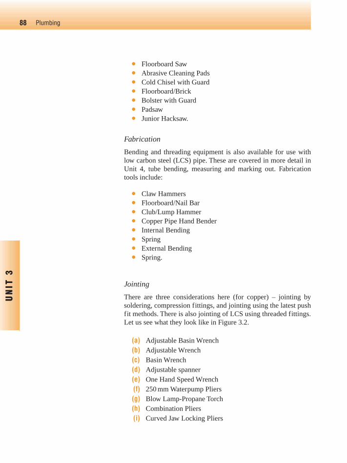
● Floorboard Saw● Abrasive Cleaning Pads● Cold Chisel with Guard● Floorboard/Brick● Bolster with Guard● Padsaw● Junior Hacksaw.
Fabrication
Bending and threading equipment is also available for use withlow carbon steel (LCS) pipe. These are covered in more detail inUnit 4, tube bending, measuring and marking out. Fabricationtools include:
● Claw Hammers● Floorboard/Nail Bar● Club/Lump Hammer● Copper Pipe Hand Bender● Internal Bending● Spring● External Bending● Spring.
Jointing
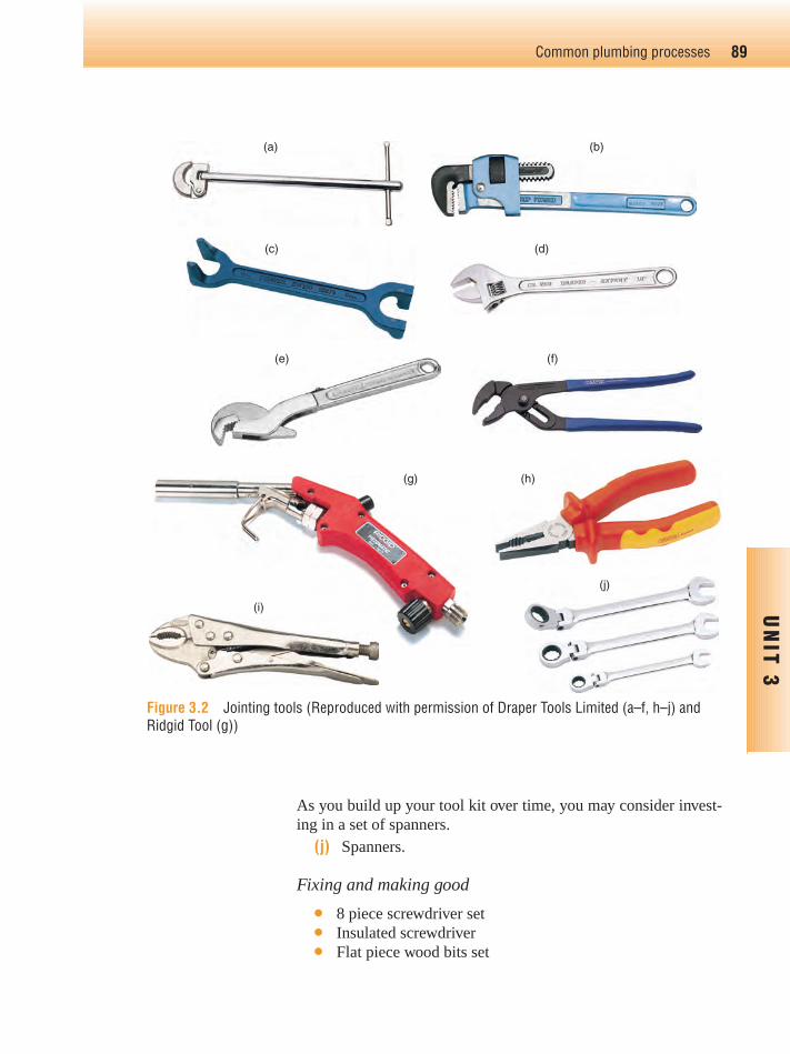
There are three considerations here (for copper) – jointing bysoldering, compression fittings, and jointing using the latest pushfit methods. There is also jointing of LCS using threaded fittings.Let us see what they look like in Figure 3.2.
(a) Adjustable Basin Wrench(b) Adjustable Wrench(c) Basin Wrench(d) Adjustable spanner(e) One Hand Speed Wrench(f) 250 mm Waterpump Pliers(g) Blow Lamp-Propane Torch(h) Combination Pliers(i) Curved Jaw Locking Pliers
88 Plumbing
UN
IT 3
Ch03-H8434.qxd 4/11/07 5:41 PM Page 88
89Common plumbing processes
UN
IT 3
Figure 3.2 Jointing tools (Reproduced with permission of Draper Tools Limited (a–f, h–j) andRidgid Tool (g))
(a)
(c) (d)
(b)
(e) (f)
(g) (h)
(j)
(i)
As you build up your tool kit over time, you may consider invest-ing in a set of spanners.
(j) Spanners.
Fixing and making good
● 8 piece screwdriver set● Insulated screwdriver● Flat piece wood bits set
Ch03-H8434.qxd 4/11/07 5:41 PM Page 89

● 150 mm pointing trowel● Masonry drill bits● High speed steel drill bits.
Other tools
● Allen keys● Immersion heater key● Sink plunger● Stop valve key● Tool box.
Specialist tools
Plumbers also use tools and equipment of a more specialist natureand these should be used in accordance with manufacturers’instructions and by personnel who have been properly instructedin their use (Figure 3.3).
90 Plumbing
UN
IT 3
Key point
Do not forget to make surethat solder wire used on watersupply systems is ‘lead free’.
Figure 3.3 Pipe freezing kit(Reproduced with permission ofRidgid Tools)
In addition to the tools and equipment, you will need materialssuch as:
● Solder wire● Fluxes approved for plumbing work (including those
suitable for wholesome water installations)● Jointing tape approved for plumbing work● Jointing compound approved for plumbing work (including
those suitable for wholesome water installations)● A range of screws and nails.
Ch03-H8434.qxd 4/11/07 5:41 PM Page 90
Tool safety maintenance checklist
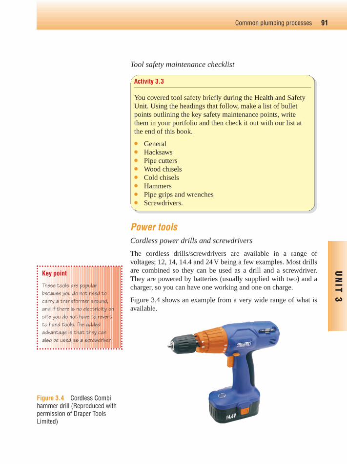
Power toolsCordless power drills and screwdrivers
The cordless drills/screwdrivers are available in a range ofvoltages; 12, 14, 14.4 and 24 V being a few examples. Most drillsare combined so they can be used as a drill and a screwdriver.They are powered by batteries (usually supplied with two) and acharger, so you can have one working and one on charge.
Figure 3.4 shows an example from a very wide range of what isavailable.
91Common plumbing processes
UN
IT 3
Activity 3.3
You covered tool safety briefly during the Health and SafetyUnit. Using the headings that follow, make a list of bulletpoints outlining the key safety maintenance points, writethem in your portfolio and then check it out with our list atthe end of this book.
● General● Hacksaws● Pipe cutters● Wood chisels● Cold chisels● Hammers● Pipe grips and wrenches● Screwdrivers.
Key point
These tools are popularbecause you do not need tocarry a transformer around,and if there is no electricity onsite you do not have to revertto hand tools. The addedadvantage is that they canalso be used as a screwdriver.
Figure 3.4 Cordless Combihammer drill (Reproduced withpermission of Draper ToolsLimited)
Ch03-H8434.qxd 4/11/07 5:41 PM Page 91

Power drills
110 VThere is a wide range of makes and models of power drills; thissection is designed to show a cross section of what is available.
Typical power ratings for 110 V drills range from 620 to 1400 W.Most drills are of variable speed and some have a reversibleaction. Drills vary in power depending on the size of motor; this inturn has a bearing on what the drill can do.
The one shown in Figure 3.5 has a ‘hammer action’ which whenengaged makes drilling through masonry easier. Not only does thedrill rotate but it also moves fractionally backwards and forwardsat high speed, giving the effect of hammering the drill into thebuilding fabric.
92 Plumbing
UN
IT 3
Figure 3.6 Screwdriver drill bits
Figure 3.5 110 V hammer drill(Reproduced with permission ofDraper Tools Limited)
A range of bits is available for powered and cordless drills for useon metal, wood, brickwork, blockwork and concrete. Core drillsare also available for drilling large diameter holes. Screwdriverbits are available in the following designs (Figure 3.6):
● These are precision made using hardened steel and are hardwearing
● The bits can be purchased individually or in sets. The typeshown slot into a purpose made bit for the drill.
Power saws
Power saws such as circular saws are used by plumbers for takingup floorboards or sheets in order to install pipework under floors(Figure 3.7).
Ch03-H8434.qxd 4/11/07 5:41 PM Page 92
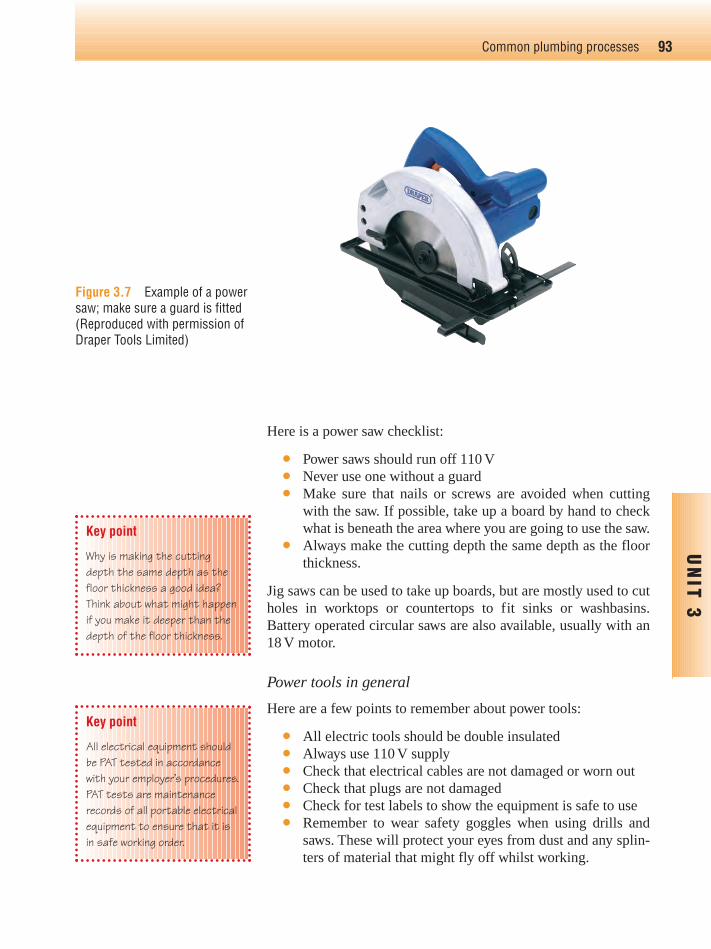
Here is a power saw checklist:
● Power saws should run off 110 V● Never use one without a guard● Make sure that nails or screws are avoided when cutting
with the saw. If possible, take up a board by hand to checkwhat is beneath the area where you are going to use the saw.
● Always make the cutting depth the same depth as the floorthickness.
Jig saws can be used to take up boards, but are mostly used to cutholes in worktops or countertops to fit sinks or washbasins.Battery operated circular saws are also available, usually with an18 V motor.
Power tools in general
Here are a few points to remember about power tools:
● All electric tools should be double insulated● Always use 110 V supply● Check that electrical cables are not damaged or worn out● Check that plugs are not damaged● Check for test labels to show the equipment is safe to use● Remember to wear safety goggles when using drills and
saws. These will protect your eyes from dust and any splin-ters of material that might fly off whilst working.
93Common plumbing processes
UN
IT 3
Figure 3.7 Example of a powersaw; make sure a guard is fitted(Reproduced with permission ofDraper Tools Limited)
Key point
Why is making the cuttingdepth the same depth as thefloor thickness a good idea?Think about what might happenif you make it deeper than thedepth of the floor thickness.
Key point
All electrical equipment shouldbe PAT tested in accordancewith your employer’s procedures.PAT tests are maintenancerecords of all portable electricalequipment to ensure that it isin safe working order.
Ch03-H8434.qxd 4/11/07 5:41 PM Page 93

Cartridge-operated tools
We covered cartridge-operated tools under Health and Safety.Remember, people under the age of 18 are not allowed to usethem. If over the age of 18, you must receive proper instructionson their use.
94 Plumbing
UN
IT 3
1. List a typical tool for each of the following:● Measuring and marking out● Cutting and preparation● Fabrication● Jointing● Fixing and making good
2. State the safety and maintenancerequirements for:● Hacksaws● Wood chisels● Pipe grips and wrenches
3. What tools would you use for:● The cutting of sheet metal● De-burring a pipe● Removing a mild steel fitting from a pipe● Notching a floor joist● Removing an immersion heater
4. Which voltage must power drills run on?a. 110 Vb. 240 Vc. 225 Vd. 415 V
5. What is a PAT test used for?
6. What is the minimum age that you canuse cartridge-operated tools?a. 18b. 20c. 21d. There is no minimum age
7. State three specific safety precautionswhen using a power saw
8. State three safety precautions when usingany power tools
Test yourself 3.2
Try this
Next time you are in a plumbing merchant’s or a tool shop,make it a point to look at the range of hand and power toolsthat are available for plumbing work. Take time to obtainhand and power tool catalogues, and look on the internet tosee what is available based on the tools listed in this unit.Prepare a list of tools you will need to include in yourplumbing tool kit. [You may have some of the tools already,compare the quality and prices of the various manufacturers].
Ch03-H8434.qxd 4/11/07 5:41 PM Page 94

Introduction
Bending, measuring and marking out is a basic essential skill for anyplumber. In this unit, we will concentrate on the bending of copperpipe, which can be done by hand (with a spring) or machine. We willalso look at LCS which, in the main, is bent by hydraulic machines.
Bending methodsWe will concentrate here on copper and LCS pipes. Plastic pipesused in domestic plumbing systems can be bent, but the main appli-cation is restricted to small-bore polythene pipes which can be posi-tioned into large radius 90° bends or offset by hand, and then clippedinto position. There are also steel preformed 90° brackets for tighterbends, into which the pipe can be clipped (see Figure 3.8).
This image was reproduced with the kind permission of Hepworthwho can be contacted on the numbers below, and you can visittheir website www.hepworthplumbing.co.uk
Technical Support Tel: 01709 856 406Fax: 01709 856 407Literature Service Tel: 01709 856 408Fax: 01709 856 409
Copper tube bendingThe type of copper tube suitable for bending is BS EN 1057–R250(previously designated as BS EN 1057; Part 1 – Table X). It istermed as half hard, and is available in straight lengths.
Other types are BS EN 1057–R220 (previously designated as BSEN 2871; Part 1 – Table Y), this type has thick walls, and is sup-plied in coils. It is not usually used internally in dwellings; it ismostly used for underground services and is available with a plas-tic coating to protect it from corrosion.
There is also BS EN 1057–R220 (previously designated as BS EN2871; Part 1 – Table W), supplied in coils and generally used formicro-bore heating installations.
We will explore copper tube in a bit more detail when we look at pipejointing in the next session. The latter two are not suitable for bendingby machine. R250 (Table X) copper pipe can be bent by using either:
● Hand or● Machine.
95Common plumbing processes
UN
IT 3
Figure 3.8 Large radius plasticbend and fixing bracket(Reproduced with permission ofHepworth Plumbing)
Key point
What do you think are theadvantages of bending piperather than using fittings?
Bending pipe rather than usingfittings has the followingadvantages:
● They produce larger radiusbends than elbow fittingsand larger radius bends haveless frictional resistancethan fittings
● Using bends costs less thanusing fittings
● Long sections of pipeworkcan be prefabricated beforeinstallation, saving time.
Tube bending,measuring and
marking out
Ch03-H8434.qxd 4/11/07 5:41 PM Page 95
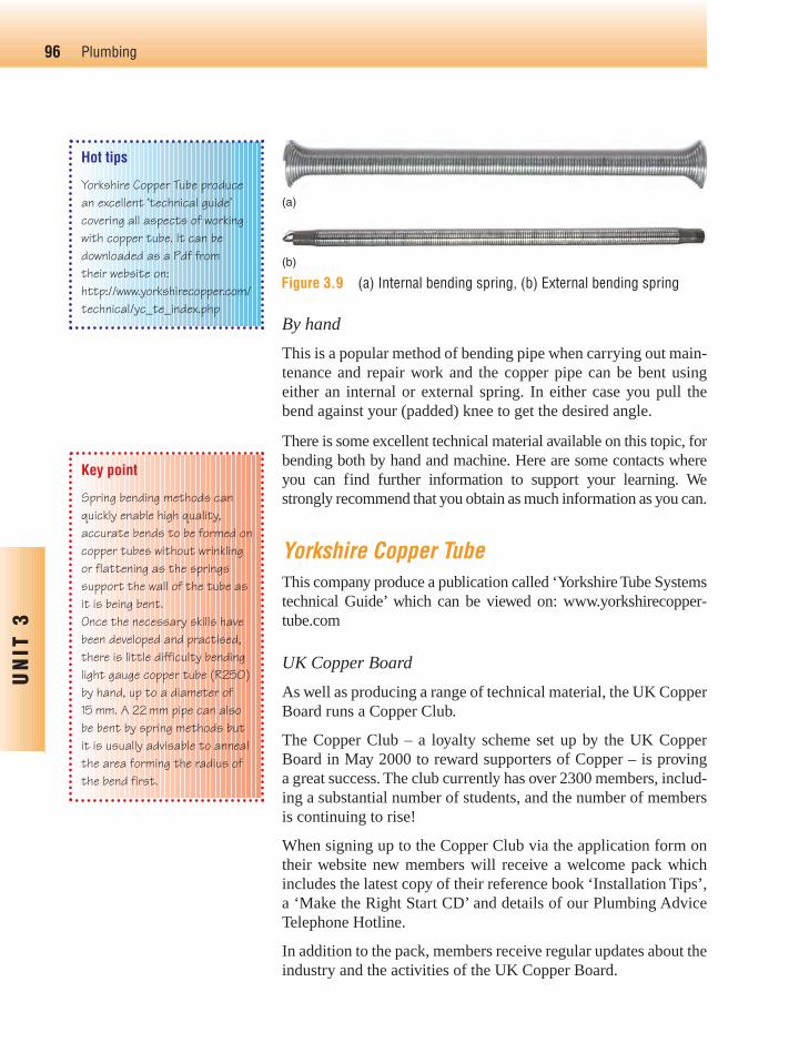
By hand
This is a popular method of bending pipe when carrying out main-tenance and repair work and the copper pipe can be bent usingeither an internal or external spring. In either case you pull thebend against your (padded) knee to get the desired angle.
There is some excellent technical material available on this topic, forbending both by hand and machine. Here are some contacts whereyou can find further information to support your learning. Westrongly recommend that you obtain as much information as you can.
Yorkshire Copper TubeThis company produce a publication called ‘Yorkshire Tube Systemstechnical Guide’ which can be viewed on: www.yorkshirecopper-tube.com
UK Copper Board
As well as producing a range of technical material, the UK CopperBoard runs a Copper Club.
The Copper Club – a loyalty scheme set up by the UK CopperBoard in May 2000 to reward supporters of Copper – is proving a great success. The club currently has over 2300 members, includ-ing a substantial number of students, and the number of membersis continuing to rise!
When signing up to the Copper Club via the application form ontheir website new members will receive a welcome pack whichincludes the latest copy of their reference book ‘Installation Tips’,a ‘Make the Right Start CD’ and details of our Plumbing AdviceTelephone Hotline.
In addition to the pack, members receive regular updates about theindustry and the activities of the UK Copper Board.
96 Plumbing
UN
IT 3
Hot tips
Yorkshire Copper Tube producean excellent ‘technical guide’covering all aspects of workingwith copper tube. It can bedownloaded as a Pdf from their website on:http://www.yorkshirecopper.com/technical/yc_te_index.php
Key point
Spring bending methods canquickly enable high quality,accurate bends to be formed oncopper tubes without wrinklingor flattening as the springssupport the wall of the tube asit is being bent.Once the necessary skills havebeen developed and practised,there is little difficulty bendinglight gauge copper tube (R250)by hand, up to a diameter of15 mm. A 22 mm pipe can alsobe bent by spring methods butit is usually advisable to annealthe area forming the radius ofthe bend first.
(a)
(b)
Figure 3.9 (a) Internal bending spring, (b) External bending spring
Ch03-H8434.qxd 4/11/07 5:41 PM Page 96
The UK Copper Board site is at: www.ukcopperboard.co.uk andtheir address is:
UK Copper Boardc/o Copper Development Association5 Grovelands Business CentreBoundary WayHemel HempsteadHertfordshire HP2 7TE
Copper Development Association
The Copper Development Association provides excellent techni-cal advice in the form of various publications, and also supportsfurther education. Their website is at: www.cda.org.uk
Setting out for hand bends using bendingspringsIt’s pretty obvious that if you tried to bend a piece of copper tubewithout supporting the wall of the pipe, the pipe would simply col-lapse, leaving a totally unacceptable result. One way of preventingthis is to use a bending spring.
Half-hard copper tubing R250 (formally table X) is the recom-mended grade for pipe bending, using either an internal or externalbending spring. Hand-made bends have to be ‘set out’ in order toform the radius of the bend, and provide accurate measurementsto a fixed point or fitting.
Hand bends should be limited to up to 22 mm diameter; someplumbers may use an internal spring for larger sizes, but this isn’trecommended or indeed allowed for in BS 5431(4) (the BritishStandard for bending springs).
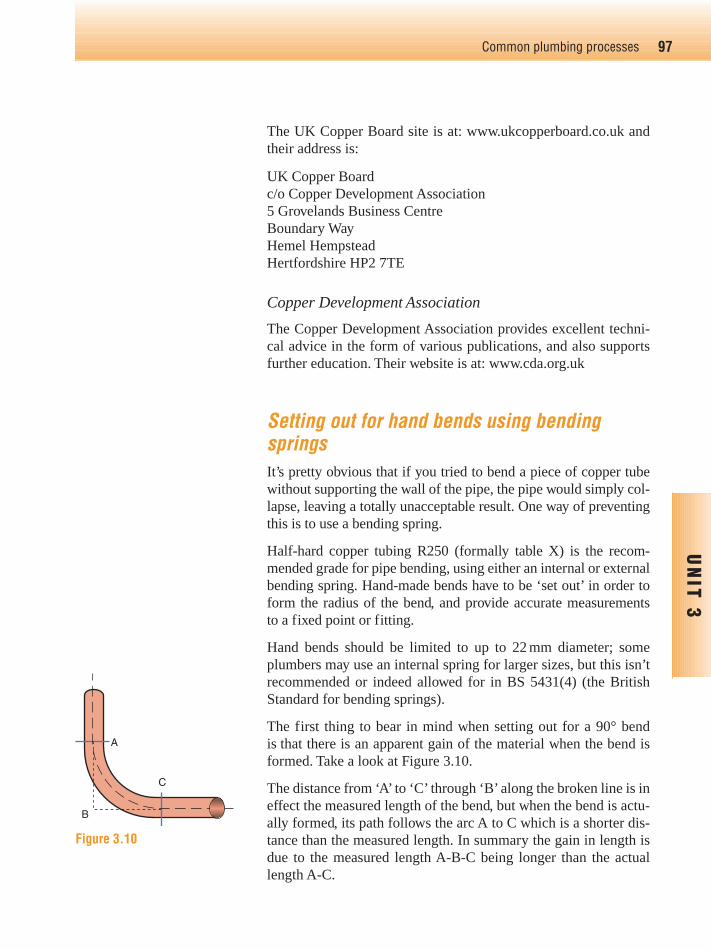
The first thing to bear in mind when setting out for a 90° bendis that there is an apparent gain of the material when the bend isformed. Take a look at Figure 3.10.
The distance from ‘A’ to ‘C’ through ‘B’ along the broken line is ineffect the measured length of the bend, but when the bend is actu-ally formed, its path follows the arc A to C which is a shorter dis-tance than the measured length. In summary the gain in length isdue to the measured length A-B-C being longer than the actuallength A-C.
97Common plumbing processes
UN
IT 3
A
C
B
Figure 3.10
Ch03-H8434.qxd 4/11/07 5:41 PM Page 97
When setting out then:
● Allowances have to be made for the ‘gain in material’● The bend must be pulled in the right position in relation to
the fixed point.
Step by step to setting out● Decide on the centre line radius of the bend, which (unless
given on a drawing or specification) most practitioners usu-ally determine as four times the diameter of the pipe (4D),although Yorkshire Copper Tube recommend five times
● The length of the pipe occupied by a 90° bend can be calcu-lated using the formula:
● Next we’ll assume that a 15 mm pipe is to be bent to a radiusof 4D and we need to find out how much pipe will be takenup by the bend, so:
Radius of bend is 4D, which is 4 � 15 � 60 mm.
Now use the formula:
So:
Length of bend � 94.26 mm, say 95 mm.
● The next step when making the bend is to measure and markoff the length required from a fixed point (which could be where the pipe is going to enter a fitting for example) tothe centre line of the bend (see procedure indicated atFigure 3.11a)
● Then divide the calculated length of pipe by three, which inour case gives three equal measurements of approximately32 mm
● From the original centre line, mark 32 mm forward and64 mm back (see procedure indicated at Figure 3.11b)
60 � �2 3.1424
Radius � �2 3.1424
Radius � �2 3.1424
98 Plumbing
UN
IT 3
Ch03-H8434.qxd 4/11/07 5:41 PM Page 98

99Common plumbing processes
UN
IT 3Key point
Bending copper pipe using aspring is something you can tryand practice at home. Use thismaterial as a guide, and have ago at setting out and forming90° bends. You can also tryforming an offset. Use aninternal spring, and start offwith 15 mm copper tube andwork up to 22 mm.
● The bend is then pulled making sure that it is kept within theconfines of the three 32 mm measurements, this will makesure that the centre will be the correct distance from thefixed point
● This setting out technique can also be used for offsets, but abend of 45°/135° will only require half the length of pipe asthat of a 90° bend
● You’re now ready to make the bend
Machine bending
For this image we have used 22 mm copper pipe rather than 15 mm as given inthe worked example above. This means we are using different measurementswhich work out at 3 equal measurements of approximately 46 mm
Measure and mark off the lengthrequired from the fixed point
Fixed point
Measured length
Fixed point
Measured length
46 mm forward and92 mm back
46 mm 46 mm 46 mm
(a)
(b)Figure 3.11
● It’s advisable to use a template, most plumber’s will use a90° set square or similar
● Insert the spring, it may be an idea to lubricate it first usingoil or grease
● Pull the bend gently around the knee to an angle slightlyover 90° and then pull it back to 90° and check its accuracyagainst the template before removing the spring
● Forming offsets, in order to route pipe work around obs-tacles, is best done by making a template out of strong wiresuch as welding rod or similar, and then bending the pipe tomatch the template.
Why do you think it’s necessary to overpull the bend? Youdon’t have to write anything down here, but have a think beforemoving on.
Overpulling the bend and then returning to 90° will release thetension between the spring and the pipe wall and make it easier toremove the spring.
This is the most common method used for bending copper tube.Bending machines can be either hand held, or free standing, and
Ch03-H8434.qxd 4/11/07 5:41 PM Page 99
100 Plumbing
UN
IT 3
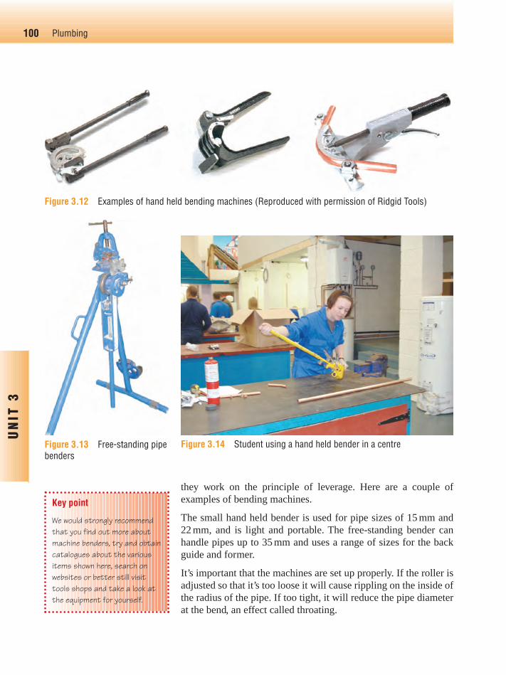
Figure 3.12 Examples of hand held bending machines (Reproduced with permission of Ridgid Tools)
Figure 3.13 Free-standing pipebenders
Figure 3.14 Student using a hand held bender in a centre
they work on the principle of leverage. Here are a couple of examples of bending machines.
The small hand held bender is used for pipe sizes of 15 mm and22 mm, and is light and portable. The free-standing bender canhandle pipes up to 35 mm and uses a range of sizes for the backguide and former.
It’s important that the machines are set up properly. If the roller isadjusted so that it’s too loose it will cause rippling on the inside ofthe radius of the pipe. If too tight, it will reduce the pipe diameterat the bend, an effect called throating.
Key point
We would strongly recommendthat you find out more aboutmachine benders, try and obtaincatalogues about the variousitems shown here, search onwebsites or better still visittools shops and take a look atthe equipment for yourself.
Ch03-H8434.qxd 4/11/07 5:41 PM Page 100
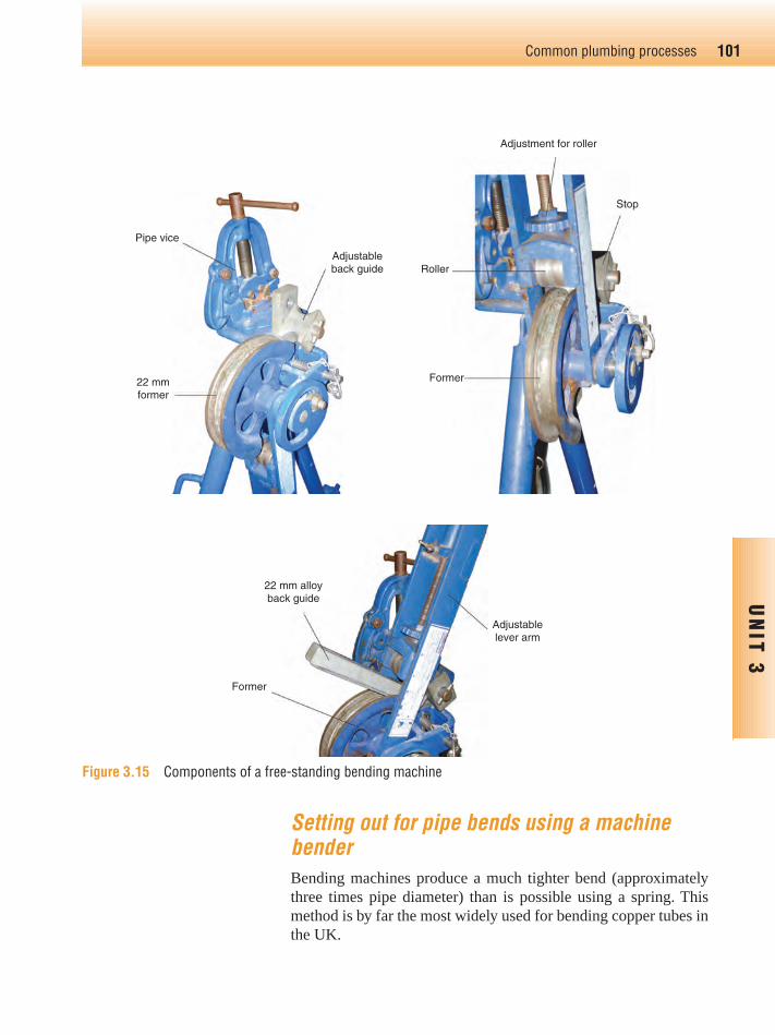
Setting out for pipe bends using a machinebenderBending machines produce a much tighter bend (approximatelythree times pipe diameter) than is possible using a spring. Thismethod is by far the most widely used for bending copper tubes inthe UK.
101Common plumbing processes
UN
IT 3
Pipe vice
22 mmformer
Adjustableback guide
Adjustment for roller
Roller
Former
Stop
22 mm alloyback guide
Former
Adjustablelever arm
Figure 3.15 Components of a free-standing bending machine
Ch03-H8434.qxd 4/11/07 5:41 PM Page 101

Here we’ll look at three types of machine bends:
● 90° or square bend● Offset● Passover sets.
90° or square bends
When forming square bends the bend can be set to either theinside of the bend and inside of the former, or outside of the bendand outside of the former; the procedures are almost identical,both methods are equally correct and will produce perfect bends.Here’s what to do when setting the bend to the outside of theformer:
● Mark the pipe to the required measurement using a pencil,this should be taken from the back of the bend to the fixedpoint
● Make sure that the pipe is pushed fully into the former andis also inserted in the stop
● Place the alloy guide over the pipe (don’t use the steel ver-sion, as these are used for bending low carbon steel tubes)
102 Plumbing
UN
IT 3 Figure 3.16 Machine Bend
Measurement
Figure 3.17 Completed 90°Machine Bend
450 mm
Fixed point
Measurement to theback of the bend
450 mmTo the back of the bend
Fixedpoint
90° Machine bend in copper
Pull
Stop
Adjustable Roller
Back Guide
Back of Former
Tube Tube
Back of Bend
Fixed point
450 mm
90°
Former
Figure 3.18 Tube Position in Former
Ch03-H8434.qxd 4/11/07 5:41 PM Page 102
● Adjust the pressure onto the guide enough to hold the pipein position (if adjustable type)
● The square is then placed against the mark on the pipe andadjusted until the square touches the outside of the former
● Make a final adjustment to ensure the correct bendingposition
● Pull the lever arm to bend the pipe slightly over the required90° angle as this will counteract the spring back in the bend
Making a return bend, or bending the same pipe again in a differentposition is achieved using the same technique, only now the firstbend becomes the fixed point.
You may hear offset being referred to as a double set, with an ordin-ary single bend being known as a set. The machine is set up in thesame way as that of the 90° bend. There are a couple of variationsfor producing an offset, it can be produced by measurements fromthe site, or by producing a template, which could be made fromstrong wire, or drawn on the floor in chalk or on a piece of sheettimber.
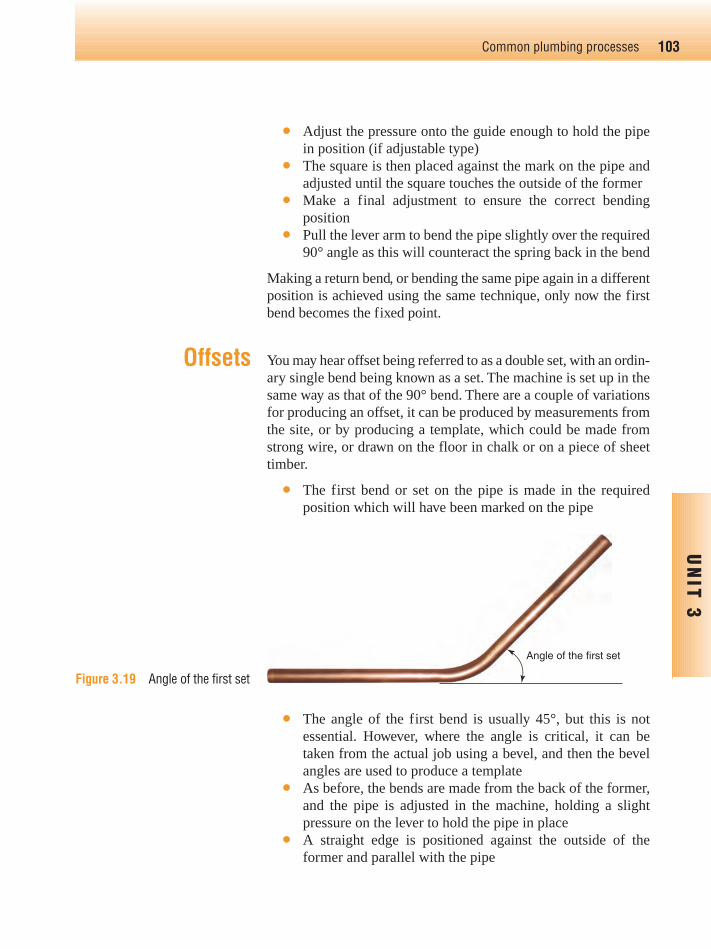
● The first bend or set on the pipe is made in the requiredposition which will have been marked on the pipe
● The angle of the first bend is usually 45°, but this is notessential. However, where the angle is critical, it can betaken from the actual job using a bevel, and then the bevelangles are used to produce a template
● As before, the bends are made from the back of the former,and the pipe is adjusted in the machine, holding a slightpressure on the lever to hold the pipe in place
● A straight edge is positioned against the outside of theformer and parallel with the pipe
103Common plumbing processes
UN
IT 3
Offsets
Figure 3.19 Angle of the first set
Angle of the first set
Ch03-H8434.qxd 4/11/07 5:41 PM Page 103

Pass-over bends
These are used to clear other obstacles such as other pipes, andcan be either pass-over offsets (see Figure 3.22) or crank pass-overbends (see Figure 3.23).
The measurements for a pass-over bend are taken in the same wayas an ordinary offset. The angle of the first pull will be governedby the size of the obstacle it has to ‘pass over’. It is to be made surethat the first bend is not too sharp or it will be difficult whenpulling the offset bend (Figure 3.24).
● The pipe in the machine is adjusted until the required meas-urement for the offset has been achieved. Alternatively, ifusing a template, when the first bend has been pulled it isremoved from the machine, placed on the template, andmarked off in the position of the second bend
● The second bend is now pulled by applying pressure to thelever arm and bending the pipe until the pipe legs are parallel.
104 Plumbing
UN
IT 3
Figure 3.20 Pulling the offset
Back of Machine
Former
CompletedDouble set
Directionof lever
Pipe
Guide
RequiredMeasurementof Offset
Pipe
Figure 3.21 Completed offset
Requiredmeasurement
of offset
Completed Offset
Measurementof offset
Figure 3.22 Pass-over offset
Ch03-H8434.qxd 4/11/07 5:41 PM Page 104

105Common plumbing processes
UN
IT 3
Figure 3.23 ‘Crank’ pass-over bend
Key point
We make every effort to explainhow to bend copper pipe inthese pages, but the best wayto learn is by practice. Followthis information carefully,particularly when working onsite.
Set ‘x’
Set ‘z’
Dotted line indicates tube after bending. i.e. until in line with straight edge
Position of pipebefore bending
Dimension ‘y’
Add 2–3 mm to (y) dimension
Measurement of crank passover
x z
y
Figure 3.24
Figure 3.25
A straight edge is placed over the bend at the distance of the obs-tacle and the pipe is marked. These will be the back of the finishedoffsets as shown in Figure 3.25.
The pipe is then returned to the machine, and when the first marklines up with the former, the first pipe is turned around in themachine; the second mark is lined up in the former and pulled tocomplete the pass-over.
Low carbon steel (LCS) pipe bendingIn domestic plumbing applications, steel pipes are bent using ahydraulic pipe bender.
Use of hydraulic machines
Hydraulic machines are needed to bend LCS tubes. This is due tothe strength of the material, and the thickness of the pipe. Because
Ch03-H8434.qxd 4/11/07 5:41 PM Page 105
of this you do not need to fully support the pipe with a back guard,as with copper pipe.
Hydraulic bending machines are used to form all bends, including90° and offsets.
The hydraulic mechanism is usually oil based, and because liquidsare incompressible, once under pressure it can exert considerableforce on the pipe.
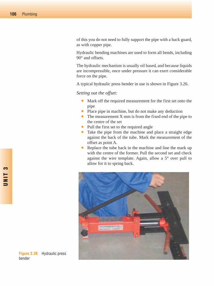
A typical hydraulic press bender in use is shown in Figure 3.26.
Setting out the offset:
● Mark off the required measurement for the first set onto thepipe
● Place pipe in machine, but do not make any deduction● The measurement X mm is from the fixed end of the pipe to
the centre of the set● Pull the first set to the required angle● Take the pipe from the machine and place a straight edge
against the back of the tube. Mark the measurement of theoffset as point A.
● Replace the tube back in the machine and line the mark upwith the centre of the former. Pull the second set and checkagainst the wire template. Again, allow a 5° over pull toallow for it to spring back.
106 Plumbing
UN
IT 3
Figure 3.26 Hydraulic pressbender
Ch03-H8434.qxd 4/11/07 5:41 PM Page 106
107Common plumbing processes
UN
IT 3
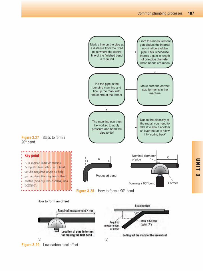
From this measurementyou deduct the internal
nominal bore of thepipe.This is because
there’s a gain in lengthof one pipe diameter
when bends are made
Put the pipe in thebending machine andline up the mark with
the centre of the former
The machine can thenbe worked to apply
pressure and bend thepipe to 90°
Due to the elasticity of the metal, you need totake it to about another5° over the 90 to allow
it to ‘spring back’
Make sure the correctsize former is in the
machine
Mark a line on the pipe ata distance from the fixedpoint where the centre
line of the finished bendis required
FormerForming a 90° bend
Proposed bend
Nominal diameterof pipe
XX
Figure 3.27 Steps to form a 90° bend
Figure 3.28 How to form a 90° bend
Figure 3.29 Low carbon steel offset
Key point
It is a good idea to make atemplate from steel wire bentto the required angle to helpyou achieve the required offsetprofile (see Figures 3.29(a) and3.29(b)).
(a) (b)
How to form an offset
Ch03-H8434.qxd 4/11/07 5:41 PM Page 107

Introduction
In domestic plumbing installations, the main pipework materialsyou will work with will be:
● Copper● Low carbon steel and malleable iron fittings● Plastic.
Pipes, fittings and jointing materials acceptable for water regula-tion purposes are listed in the Water Regulations AdvisoryScheme (WRAS) Water Fittings and Materials Directory.
A WRAS symbol shows that a product has been tested forapproval and is listed in the Directory. Further information can beobtained from www.wras.co.uk.
Copper tube and fittingsCopper tube development
The first recorded use of copper for conveying water goes back toa conduit that has been dated back to 2,750 B.C., discovered at
108 Plumbing
UN
IT 3
1. Hydraulic machines are best suited forbending:a. Copper tube (BS EN 1057 – R250)b. Copper tube (BS EN 1057 – R220)c. Low carbon steel tubed. Plastic pipe
2. Which one of the following types ofcopper tube is suitable for springbending?a. BS EN 1057-R250 (formerly BS
2871; Part 1 Table x)b. BS EN 1057-R220 (formerly BS
2871; Part 1 Table y)c. BS EN 1057-R220 (formerly BS
2871; Part 1 Table w)
3. When bending copper pipe using springs,briefly explain how the spring works?
4. Hand held bending machines are usuallylimited to bend copper tubes withdiameters of up to:a. 22 mmb. 32 mmc. 42 mmd. 52 mm
5. Which of the following tools can be usedto help determine suitable bend angles?a. Internal bending springb. External bending springc. 600 mm straight edged. 600 mm folding rule
Test yourself 3.3
Pipeworkmaterial and
jointingprocesses
Ch03-H8434.qxd 4/11/07 5:41 PM Page 108
Abusir in Egypt. Copper water pipes and cisterns were also widelyused by the Romans and good examples of copper plumbing canstill be seen at the archaeological site of Herculaneum, Italy,which was uniquely preserved by the eruption of Vesuvius in79 A.D.
Historically copper tubing was expensive and only installed inprestige buildings. It was not until the development of moderntypes of fittings in the 1930s, which led to the introduction of lightgauge copper tubes, that copper plumbing systems became highlycompetitive with other materials. In 1996 the latest specificationfor copper tubes, EN 1057, was adopted across Europe.
In the UK this specification was published as BS EN 1057:1996,‘Copper and copper alloys – Seamless, round copper tubes forwater and gas in sanitary and heating applications’. It replacedthe previously familiar standard BS 2871 Part 1: 1971, ‘Copperand Copper Alloys Tubes – Copper tubes for water, gas andsanitation’.
In drawing up this standard, the opportunity was taken to ration-alise tube sizes across Europe. At first glance the changes to theBS 2871 Part 1 standard must have seemed quite extensive and theavailable options confusing.
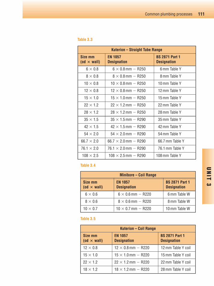
Yorkshire Copper Tube simplified this process by branding theirproducts as Yorkex, Kuterlon and Minibore in line with Tables X,Y and W in BS 2871 Part 1. Under BS EN 1057, temper condition(material strength) is designated with an ‘R’ number, the higherthe number indicating a stronger material. Tables 3.1–3.5 show therelationship of the current Yorkshire range with BS EN 1057 andBS 2871 Part 1. These tables have been reproduced with the kindpermission of Yorkshire Copper Tube.
Soft condition is denoted R220, half hard R250 and hard R290.Because of the variety of sizes, both diameter and thicknessshould be specified when ordering to BS EN 1057. For example,when ordering half hard copper tube with an outside diameterof 15 mm and a thickness of 0.7 mm (formerly 15 mm in BS 2871 Part 1 Table X tubing) the official designation is EN1057 � R250 � 15 � 0.7 mm. More simply, it can be ordered as 15 mm Yorkex.
BS EN 1057 – R250 half hard straight lengths are also available inchromium plate. They are used where pipework is exposed to theeye, and an attractive finish is required.
109Common plumbing processes
UN
IT 3
Key point
● R250 (Table X) is widelyused for domesticinstallations but should notbe used underground
● R220 (Table Y) is used forexternal undergroundinstallations, and can besupplied in either a blue orgreen (water service) oryellow (gas) plastic coating
● R220 (Table W), like Table Y,is fully annealed and is usedfor microbore heating
Ch03-H8434.qxd 4/11/07 5:41 PM Page 109

110 Plumbing
UN
IT 3
Yorkex – Half Hard Range
Size mm EN 1057 BS 2871 Part 1(od � wall) Designation Designation
6 � 0.6 6 � 0.6 mm � R250 6 mm Table X
8 � 0.6 8 � 0.6 mm � R250 8 mm Table X
10 � 0.6 10 � 0.6 mm � R250 10 mm Table X
12 � 0.6 12 � 0.6 mm � R250 12 mm Table X
15 � 0.7 15 � 0.7 mm � R250 15 mm Table X
22 � 0.9 22 � 0.9 mm � R250 22 mm Table X
28 � 0.9 28 � 0.9 mm � R250 28 mm Table X
35 � 1.2 35 � 1.2 mm � R250 35 mm Table X
42 � 1.2 42 � 1.2 mm � R250 42 mm Table X
54 � 1.2 54 � 1.2 mm � R250 54 mm Table X
Yorkex – Hard Range
Size mm EN 1057 BS 2871 Part 1(od � wall) Designation Designation
35 � 1.0 35 � 1.0 mm � R290 New size
35 � 1.2 35 � 1.2 mm � R290 33 mm Table X
42 � 1.0 42 � 1.0 mm � R290 New size
42 � 1.2 42 � 1.2 mm � R290 42 mm Table X
54 � 1.0 54 � 1.0 mm � R290 New size
54 � 1.2 54 � 1.2 mm � R290 54 mm Table X
66.7 � 1.2 66.7 � 1.2 mm � R290 66.7 mm Table X
76.1 � 1.2 76.1 � 1.2 mm � R290 76.1 mm Table X
108 � 1.5 108 � 1.5 mm � R290 108 mm Table X
133 � 1.5 133 � 1.5 mm � R290 133 mm Table X
159 � 2.0 159 � 2.0 mm � R290 159 mm Table X
Table 3.1
Table 3.2
Ch03-H8434.qxd 4/11/07 5:41 PM Page 110
111Common plumbing processes
UN
IT 3
Kuterion – Straight Tube Range
Size mm EN 1057 BS 2871 Part 1(od � wall) Designation Designation
6 � 0.8 6 � 0.8 mm � R250 6 mm Table Y
8 � 0.8 8 � 0.8 mm � R250 8 mm Table Y
10 � 0.8 10 � 0.8 mm � R250 10 mm Table Y
12 � 0.8 12 � 0.8 mm � R250 12 mm Table Y
15 � 1.0 15 � 1.0 mm � R250 15 mm Table Y
22 � 1.2 22 � 1.2 mm � R250 22 mm Table Y
28 � 1.2 28 � 1.2 mm � R250 28 mm Table Y
35 � 1.5 35 � 1.5 mm � R290 35 mm Table Y
42 � 1.5 42 � 1.5 mm � R290 42 mm Table Y
54 � 2.0 54 � 2.0 mm � R290 54 mm Table Y
66.7 � 2.0 66.7 � 2.0 mm � R290 66.7 mm Table Y
76.1 � 2.0 76.1 � 2.0 mm � R290 76.1 mm Table Y
108 � 2.5 108 � 2.5 mm � R290 108 mm Table Y
Minibore – Coil Range
Size mm EN 1057 BS 2871 Part 1(od � wall) Designation Designation
6 � 0.6 6 � 0.6 mm � R220 6 mm Table W
8 � 0.6 8 � 0.6 mm � R220 8 mm Table W
10 � 0.7 10 � 0.7 mm � R220 10 mm Table W
Kuterion – Coil Range
Size mm EN 1057 BS 2871 Part 1(od � wall) Designation Designation
12 � 0.8 12 � 0.8 mm � R220 12 mm Table Y coil
15 � 1.0 15 � 1.0 mm � R220 15 mm Table Y coil
22 � 1.2 22 � 1.2 mm � R220 22 mm Table Y coil
18 � 1.2 18 � 1.2 mm � R220 28 mm Table Y coil
Table 3.3
Table 3.5
Table 3.4
Ch03-H8434.qxd 4/11/07 5:41 PM Page 111

Methods of jointing copper tubeThis falls under three main headings:
● Compression joints● Soldered joints● Push fit joints.
Compression joints
Can be subdivided into:
● Manipulative● Non-manipulative.
The term manipulative, as used here, means to work or form theend of the tube.
Manipulative joint (Type B)
Figure 3.30 below shows a typical manipulative fitting.
Type B or manipulative fittings are used with soft copper tube andrequire the plumber to flare the tube end before the joint is assem-bled. An adaptor fits between the end of the pipe and fitting asshown. Type B compression fittings can be used to join pipesabove or below ground.
Non-manipulative joint (Type A)
Figures 3.31(a)–(d) are reproduced with the kind permission ofPegler Limited. Tel: 01302 560560; Website: www.pegler.co.uk
112 Plumbing
UN
IT 3
Key point
Where might you see chromium-plated pipework on a domesticplumbing installation? Probablythe most likely place you wouldfind chrome-plated pipe used isfor exposed pipework runs tostand alone gas fires; otherexamples would be instantaneousshowers in bath or showerrooms.
Pipe
Pipe
Assembled joint
Adapter
Flared tube
Manipulative compression fitting
Compression nut
Compensating ring
Figure 3.30 Manipulative joint
Ch03-H8434.qxd 4/11/07 5:41 PM Page 112

The following diagrams (Figures 3.31(a)–(d)) show the basicsteps required to form a non-manipulative type A joint.
Type A, or non-manipulative fittings enable the plumber to make acompression joint without carrying out any work on the tube endsother than ensuring that they are clean and cut squarely. Type Acompression fittings can be used to join pipes above ground only.
A range of brass, gunmetal, cz-resistant to dezincification, andchromium-plated brass, fitting designs, compatible with pipesizes, are available.
Soldered capillary joints
Soldered joints can be classified as soft soldered, on which we willconcentrate here, and hard soldered, such as silver and silveralloys, which is not a domestic application (Figure 3.32).
Soft soldered joints are made using two types of fittings:
● Integral solder ring● End feed solder.
113Common plumbing processes
UN
IT 3
(a) (b)
(c) (d)
Key point
What do you think is thedifference between these typesof solder jointing methods? Thedifference between the twojointing methods, between thetwo fittings is that: the solderring fitting already containssolder in the raised ring withinthe fitting (integral). When thefitting is heated up, the soldermelts (at between 180 and230�C) and the solder is drawninto the fitting by capillaryattraction. It is the sameprinciple for the end feedfitting, but this time the solderis end fed separately from aspool of wire solder.
Figure 3.31 Non-manipulativejointing process (a) The pipe is cutto length and de-burred, and anut and olive fitted, (b) Both pipeends and olives are pushed home,(c) The nuts are hand tightened,(d) The joint is completed bytightening using a spanner oradjustable grips (Reproducedwith permission of Pegler Limited)
Solder ring fitting End feed solder fittingFigure 3.32 Solder fittings
Ch03-H8434.qxd 4/11/07 5:41 PM Page 113

The jointing process
Diagrams in Figure 3.33 are reproduced with the kind permissionof Yorkshire Fittings Ltd.
Tel: 0113 270 1104 Website: www.yorkshirefittings.co.uk/
Figure 3.33 shows the jointing of an integral solder ring fitting.
● Clean and de-burr the pipe● Clean the fitting● Apply the flux● Apply heat until you see the solder appear.
There are a number of fluxes on the market that are heat activated.This means a cleaning action takes place during the heatingprocess, so you do not have to pre-clean the pipe end or fitting.When using these fluxes, you should make sure they are non-acidic, non-toxic and WRAS-approved for use on hot and coldpipework installations.
Push fit joints for copper pipes
A number of types of push fit joints are available for use on hotand cold water supplies. Here is a typical example, illustrationsupplied by Hepworth from their Hep2O range (Figure 3.34).
They are made from plastic. A grab ring is used to lock the pipe inplace and a neoprene ‘O’ ring makes it water-tight. The fittings are
114 Plumbing
UN
IT 3
Figure 3.33 Reproduced with permission of YorkshireFittings Ltd
Wedge Support Ring
Grab Wedge
Retaining Cap
‘O’R ing
Figure 3.34 Reproduced withpermission of Hepworth Plumbing
Ch03-H8434.qxd 4/11/07 5:41 PM Page 114
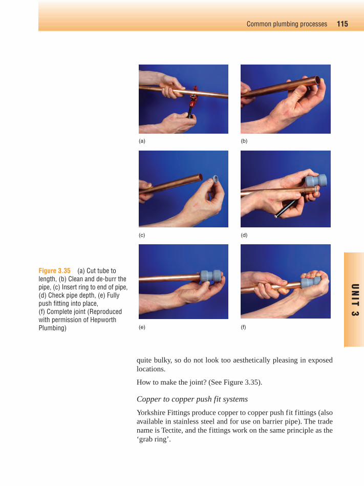
quite bulky, so do not look too aesthetically pleasing in exposedlocations.
How to make the joint? (See Figure 3.35).
Copper to copper push fit systems
Yorkshire Fittings produce copper to copper push fit fittings (alsoavailable in stainless steel and for use on barrier pipe). The tradename is Tectite, and the fittings work on the same principle as the‘grab ring’.
115Common plumbing processes
UN
IT 3
(a) (b)
(c) (d)
(e) (f)
Figure 3.35 (a) Cut tube tolength, (b) Clean and de-burr thepipe, (c) Insert ring to end of pipe,(d) Check pipe depth, (e) Fullypush fitting into place, (f) Complete joint (Reproducedwith permission of HepworthPlumbing)
Ch03-H8434.qxd 4/11/07 5:41 PM Page 115
Example of a Tectite push fit tee fitting.
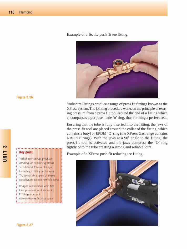
Yorkshire Fittings produce a range of press fit fittings known as theXPress system. The jointing procedure works on the principle of exert-ing pressure from a press fit tool around the end of a fitting whichencompasses a purpose made ‘o’ ring, thus forming a perfect seal.
Ensuring that the tube is fully inserted into the fitting, the jaws ofthe press-fit tool are placed around the collar of the fitting, whichcontains a butyl or EPDM ‘O’ ring (the XPress Gas range containsNBR ‘O’ rings). With the jaws at a 90� angle to the fitting, thepress-fit tool is activated and the jaws compress the ‘O’ ringtightly onto the tube creating a strong and reliable joint.
Example of a XPress push fit reducing tee fitting.
116 Plumbing
UN
IT 3
Key point
Yorkshire Fittings producecatalogues explaining aboutTectile and XPress fittings,including jointing techniques.Try to obtain copies of thesecatalogues to see how it’s done.
Images reproduced with thekind permission of YorkshireFittings contactwww.yorkshirefittings.co.uk
Figure 3.36
Figure 3.37
Ch03-H8434.qxd 4/11/07 5:42 PM Page 116
Low carbon steel (LCS) pipe and fittingsOften referred to as mild steel, low carbon steel pipe is supplied inthree grades:
● Light – which is identified by the colour code brown● Medium – colour code blue● Heavy – colour code red.
It can be supplied either in a painted black finish, or with galvan-ised coating.
Generally speaking, light-grade tube is not used on plumbingpipework. You are most likely to work on medium-grade pipes,and occasionally heavy grade.
Medium and heavy grades are available in 6 m lengths, rangingfrom 6 to 150 mm diameter, specified as nominal bore.
Methods of jointing
For domestic installations, there are two main jointing methods:
● Threaded joints● Compression joints.
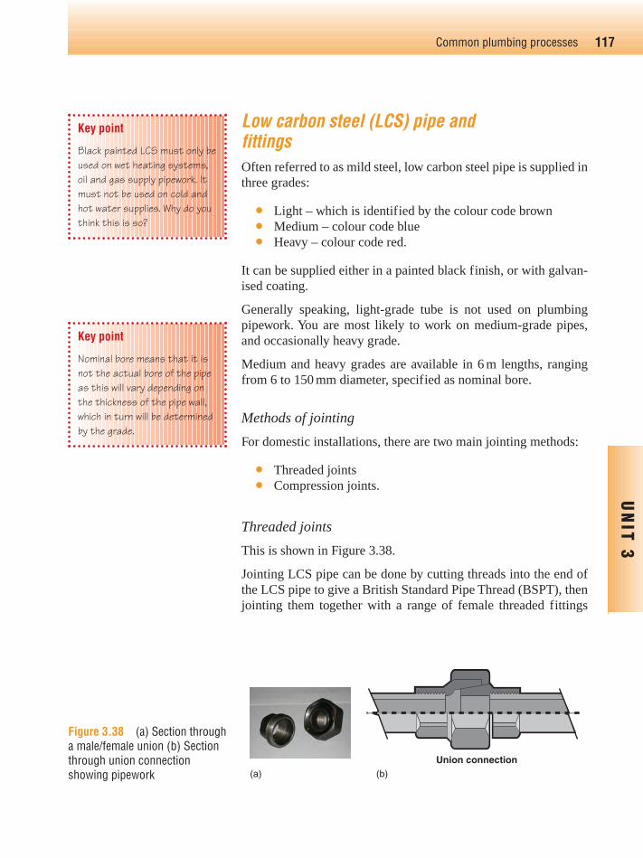
Threaded joints
This is shown in Figure 3.38.
Jointing LCS pipe can be done by cutting threads into the end ofthe LCS pipe to give a British Standard Pipe Thread (BSPT), thenjointing them together with a range of female threaded fittings
117Common plumbing processes
UN
IT 3
Key point
Black painted LCS must only beused on wet heating systems,oil and gas supply pipework. Itmust not be used on cold andhot water supplies. Why do youthink this is so?
Key point
Nominal bore means that it isnot the actual bore of the pipeas this will vary depending onthe thickness of the pipe wall,which in turn will be determinedby the grade.
Union connection(b)(a)
Figure 3.38 (a) Section througha male/female union (b) Sectionthrough union connectionshowing pipework
Ch03-H8434.qxd 4/11/07 5:42 PM Page 117
made from steel or malleable iron (Figure 3.39). The threads arecut using stocks and dies; the stocks being the body and handle ofthe tool, the dies being the actual cutter.
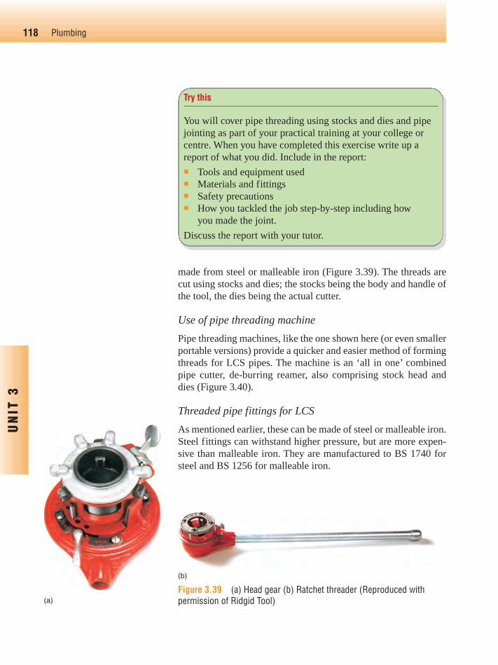
Use of pipe threading machine
Pipe threading machines, like the one shown here (or even smallerportable versions) provide a quicker and easier method of formingthreads for LCS pipes. The machine is an ‘all in one’ combinedpipe cutter, de-burring reamer, also comprising stock head anddies (Figure 3.40).
Threaded pipe fittings for LCS
As mentioned earlier, these can be made of steel or malleable iron.Steel fittings can withstand higher pressure, but are more expen-sive than malleable iron. They are manufactured to BS 1740 forsteel and BS 1256 for malleable iron.
118 Plumbing
UN
IT 3
Try this
You will cover pipe threading using stocks and dies and pipejointing as part of your practical training at your college orcentre. When you have completed this exercise write up areport of what you did. Include in the report:● Tools and equipment used● Materials and fittings● Safety precautions● How you tackled the job step-by-step including how
you made the joint.
Discuss the report with your tutor.
(a)
(b)
Figure 3.39 (a) Head gear (b) Ratchet threader (Reproduced withpermission of Ridgid Tool)
Ch03-H8434.qxd 4/11/07 5:42 PM Page 118

Malleable iron fittings are adequate for domestic installations and,again like copper tube fittings, there is a wide range available.
Compression joints
There are a number of manufacturers’ designs for compressionjoints.
Here is a typical example (Figure 3.41).
The fitting is designed to enable steel pipes to be joined withoutthreading. Made of malleable iron, they use locking rings andseals which are tightened onto the pipe. They can be used on waterand gas supplies, and although more expensive than threadedjoints, they do save time on installation.
119Common plumbing processes
UN
IT 3
Key point
Due to the way in whichscrewed joints are made andinstalled (rotated in the pipe),it is sometimes difficult toremove or assemble lengths ofpipework. Where this is thecase, a union connector like theone shown in Figures 3.38(a)and 3.38(b) which allows thepipework joint to be ‘broken’,should be used.
Compression coupling being used
Stainless steelbacking washer
Rubber compressionring
Figure 3.40 Pipe threadingmachine (Reproduced withpermission of Ridgid Tool)
Figure 3.41 Compression fitting
Ch03-H8434.qxd 4/11/07 5:42 PM Page 119
Plastic tube and fittingsPlastic pipes and fittings fall into a number of categories: Polythene,Propylene (pp) and Polyethylene (MDPE), all of which are by-products of polymerisation of ethers:
● BS 4991: Propylene copolymer for pressure pipe should notbe used in installations where the working temperatureexceeds 20°C
● BS 6572: Blue polythene pipes up to a nominal size of63 mm for below ground supply of wholesome water
● BS 6730: Black polythene pipes up to a nominal size of63 mm for above ground supply of wholesome water.
Other plastic pipes used for hot and cold water installation,wastes and overflows are:
● BS 7291 Part 1: polybutylene (PB) pipes (10–35 mm)● BS 7291 Part 3: Cross-linked polyethylene (PE-X) pipes
(10–35 mm)● BS 7291 Part 4: Chlorinated polyvinyl; (PVC-C) pipes
(12–63 mm) and unplasticised polyvinyl (UPVC)● ABS – Acrylonitrile butadiene styrene – No British standard
is available for the material and it is not suitable for use onhot water services.
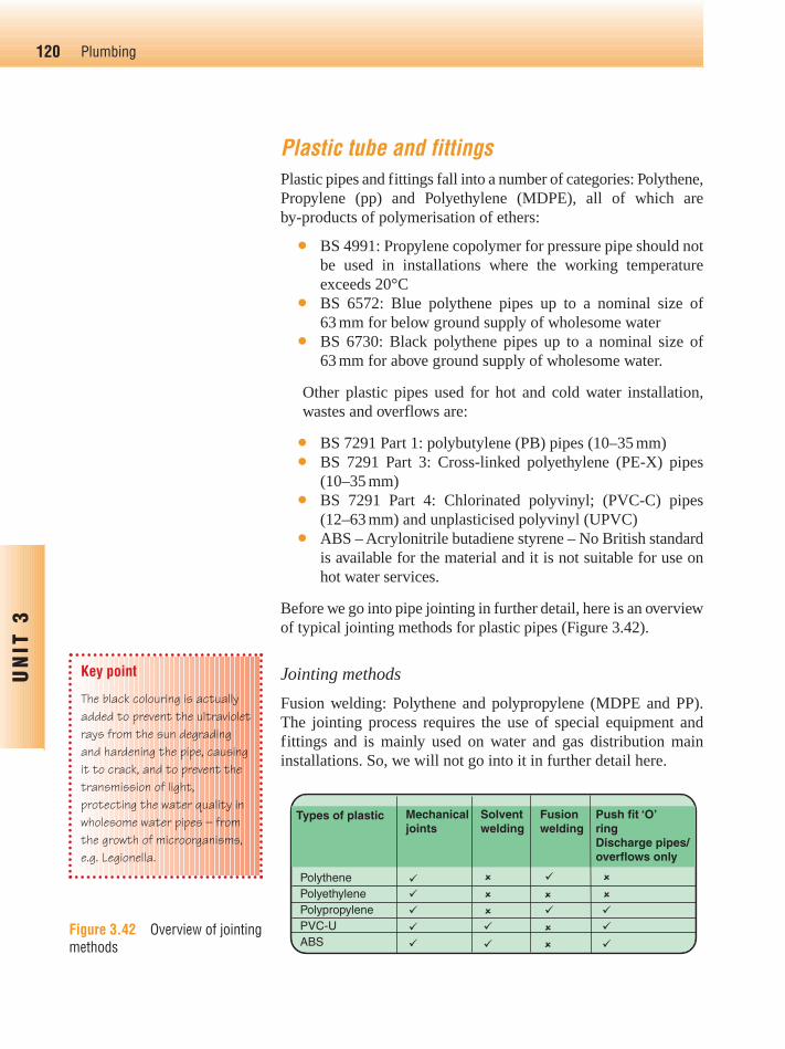
Before we go into pipe jointing in further detail, here is an overviewof typical jointing methods for plastic pipes (Figure 3.42).
Jointing methods
Fusion welding: Polythene and polypropylene (MDPE and PP).The jointing process requires the use of special equipment andfittings and is mainly used on water and gas distribution maininstallations. So, we will not go into it in further detail here.
120 Plumbing
UN
IT 3
Key point
The black colouring is actuallyadded to prevent the ultravioletrays from the sun degradingand hardening the pipe, causingit to crack, and to prevent thetransmission of light,protecting the water quality inwholesome water pipes – fromthe growth of microorganisms,e.g. Legionella.
Types of plastic Mechanicaljoints
Solventwelding
Fusionwelding
Push fit ‘O’ringDischarge pipes/overflows only
PolythenePolyethylenePolypropylenePVC-UABS
��
�
�
� �
��
��
�
�
�
��
�
�
�
�
�
Figure 3.42 Overview of jointingmethods
Ch03-H8434.qxd 4/11/07 5:42 PM Page 120
Mechanical jointing:
This applies to the jointing of:
● Polythene/Polyethylene pipework● ABS, PVC-U and PVC-C.
Polythene/Polyethylene pipe. It is used for underground watermains, and is identified by its blue colouring. It can also be foundon internal cold water services, and is coloured black.
The joints are made using metallic or plastic (e.g. polypropylene)compression fittings. The jointing process involves:
● Cutting the pipe to the required length● De-burring the pipe inside and out● Sliding the cap nut and compression ring onto the pipe and
inserting the approved liner into the pipe● Making sure the pipe is fully inserted into the fitting and
hand tightened● Completing the tightening process using adjustable grips or
spanners.
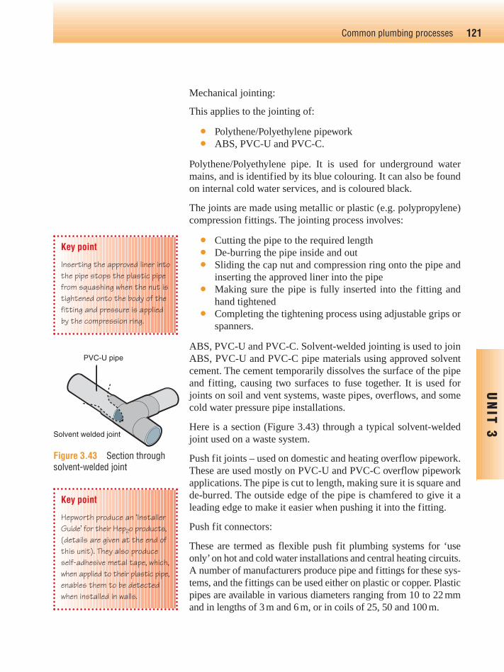
ABS, PVC-U and PVC-C. Solvent-welded jointing is used to joinABS, PVC-U and PVC-C pipe materials using approved solventcement. The cement temporarily dissolves the surface of the pipeand fitting, causing two surfaces to fuse together. It is used forjoints on soil and vent systems, waste pipes, overflows, and somecold water pressure pipe installations.
Here is a section (Figure 3.43) through a typical solvent-weldedjoint used on a waste system.
Push fit joints – used on domestic and heating overflow pipework.These are used mostly on PVC-U and PVC-C overflow pipeworkapplications. The pipe is cut to length, making sure it is square andde-burred. The outside edge of the pipe is chamfered to give it aleading edge to make it easier when pushing it into the fitting.
Push fit connectors:
These are termed as flexible push fit plumbing systems for ‘useonly’on hot and cold water installations and central heating circuits.A number of manufacturers produce pipe and fittings for these sys-tems, and the fittings can be used either on plastic or copper. Plasticpipes are available in various diameters ranging from 10 to 22 mmand in lengths of 3 m and 6 m, or in coils of 25, 50 and 100 m.
121Common plumbing processes
UN
IT 3
Key point
Inserting the approved liner intothe pipe stops the plastic pipefrom squashing when the nut istightened onto the body of thefitting and pressure is appliedby the compression ring.
Key point
Hepworth produce an ‘InstallerGuide’ for their Hep2o products,(details are given at the end ofthis unit). They also produceself-adhesive metal tape, which,when applied to their plastic pipe,enables them to be detectedwhen installed in walls.
PVC-U pipe
Solvent welded joint
Figure 3.43 Section throughsolvent-welded joint
Ch03-H8434.qxd 4/11/07 5:42 PM Page 121

Many flexible push fit plumbing systems are manufactured frompolybutylene (this is part of the polyolefin family of plastics) andallow the permeation of oxygen through the pipe wall. Therefore,polybutylene pipe is also available with a protective barrier wall to prevent occurrence of permeation, this is appropriately named‘barrier pipe’.
Barrier pipes should ideally be used in vented and sealed heatingsystems, reducing the risk of system corrosion, especiallyinstances where an inhibiter is not used. Barrier pipe conforms tothe requirements of BS 7291 Parts 1 and 2. The type of fittingused is the same as in Figure 3.34.
How to make the joint
The instructions are as follows and as shown in Figure 3.44.
122 Plumbing
UN
IT 3
(a) (b)
(c) (d)
Figure 3.44 (a) Cut pipe tolength and de-burr (b) Insertapproved support liner (c) Positionpush fit fitting (d) Complete thejoint (Reproduced with permissionof Hepworth Plumbing)
Jointing different metalsFittings that are designed to join copper to plastic are available.These are of mechanical type and are available in either metallic orplastic finish. Fittings for jointing copper to LCS are also available.
Lead pipework is no longer allowed for new installations, but itmay be necessary to join onto an existing supply in order to extend
Ch03-H8434.qxd 4/11/07 5:42 PM Page 122
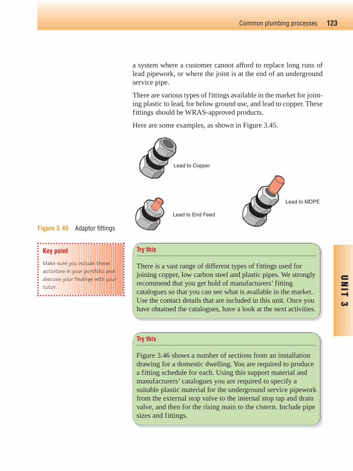
a system where a customer cannot afford to replace long runs oflead pipework, or where the joint is at the end of an undergroundservice pipe.
There are various types of fittings available in the market for joint-ing plastic to lead, for below ground use, and lead to copper. Thesefittings should be WRAS-approved products.
Here are some examples, as shown in Figure 3.45.
123Common plumbing processes
UN
IT 3
Key point
Make sure you include theseactivities in your portfolio anddiscuss your findings with yourtutor.
Try this
There is a vast range of different types of fittings used forjoining copper, low carbon steel and plastic pipes. We stronglyrecommend that you get hold of manufacturers’ fittingcatalogues so that you can see what is available in the market.Use the contact details that are included in this unit. Once youhave obtained the catalogues, have a look at the next activities.
Try this
Figure 3.46 shows a number of sections from an installationdrawing for a domestic dwelling. You are required to producea fitting schedule for each. Using this support material andmanufacturers’ catalogues you are required to specify asuitable plastic material for the underground service pipeworkfrom the external stop valve to the internal stop tap and drainvalve, and then for the rising main to the cistern. Include pipesizes and fittings.
Lead to MDPE
Lead to Copper
Lead to End Feed
Figure 3.45 Adaptor fittings
Ch03-H8434.qxd 4/11/07 5:42 PM Page 123

124 Plumbing
UN
IT 3
Try this
This installation is to be in copper (Figure 3.47). Here youneed to:
1. Specify the grade of copper to be used2. Specify the type of jointing method to be used and why3. Using this support text and manufacturers’ catalogues
produce a fitting schedule only for the pipeworkinstallation. Include the crossover.
Drain and Stop Valve
Rising Main
Cistern adequatelysupported
Cold water supplypipe
Insulated CWSC including service valve and pipe work
Roof spaceinsulation
Warning oroverflow pipe
Service pipe notless than 750 mmbelow ground level
Drinkingwaterdraw-off
Propertyboundary
Access coverto stop valve and, if applicable, the meter
Gooseneck(except forpolythene services)
Ferrule
MainExternal stop valve
Communication pipe
Pipe duct sealed at both ends to prevent soil and moistureentering pipe. The pipe must beinsulated if less than 750 mmfrom the external wall
Figure 3.46
Ch03-H8434.qxd 4/11/07 5:42 PM Page 124

125Common plumbing processes
UN
IT 3
Try this
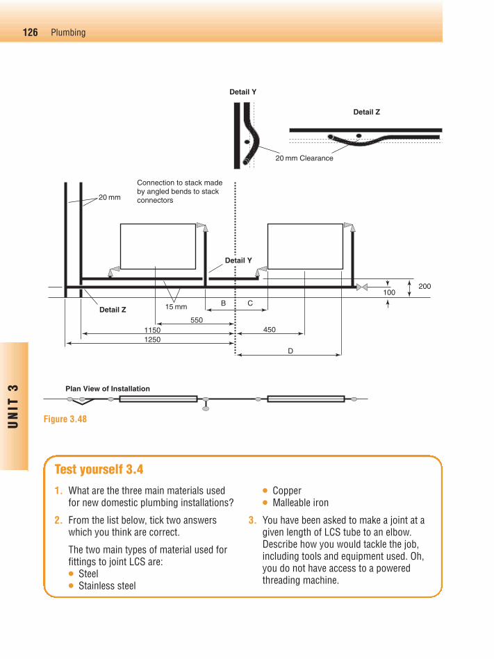
This heating installation is to be in LCS (Figure 3.48).
1. Specify the grade of LCS to be used2. Using this support material and manufacturers’
catalogues, produce a fitting schedule only for thepipework installation. Include the crossover.
Figure 3.47
22 mm Hot 15 mm Cold
Bend
1050450
400 550
1150500
Y
Detail YPositions anddimensions to suit the fittingsprovided by the centre
Y Y
Z22 mm
15 mm
15 mm15 mm
Z15 mm
15 mm100200
400
Detail Z
20 mm15 mm
Ch03-H8434.qxd 4/11/07 5:42 PM Page 125
126 Plumbing
UN
IT 3
20 mm
Detail Z
11501250
Plan View of Installation
Connection to stack madeby angled bends to stackconnectors
15 mm
550450
100200
D
B
Detail Y
C
Detail Y
Detail Z
20 mm Clearance
Figure 3.48
1. What are the three main materials usedfor new domestic plumbing installations?
2. From the list below, tick two answerswhich you think are correct.
The two main types of material used forfittings to joint LCS are:● Steel● Stainless steel
● Copper● Malleable iron
3. You have been asked to make a joint at agiven length of LCS tube to an elbow.Describe how you would tackle the job,including tools and equipment used. Oh,you do not have access to a poweredthreading machine.
Test yourself 3.4
Ch03-H8434.qxd 4/11/07 5:42 PM Page 126
Introduction
In this section, we will take a look at the various types of fixingdevices, such as screws and plugs. Different types of clips andbrackets are used for securing the pipework, so that it looks neat,and is kept in the position it should be. Fixings should also providesufficient support to the pipework or fittings so that they with-stand possible accidental damages from people treading on it,children pulling at it and so on.
As a plumber you will be required to fix the pipework, sanitaryappliances, boilers and radiators to various surfaces. You will alsoneed to know how to refit boards and access traps in timber floors.
Fixing devicesThese include:
● Brass wood screws● Self-tapping screws● Turn threaded wood screws● Steel countersunk screws● Chipboard screws● Mirror screws● Plastic wall plugs● Plastic board fixings● Cavity fixings● Nails● Corrosion-resistant (plated) screws.
127Common plumbing processes
UN
IT 3
Fixing devices,pipe supports and
brackets
Try this
We expect you to do some additional work in this section.There are so many types of fixings, supports and bracketsthat you need to obtain manufacturers’ catalogues to find outinformation for yourself.
Try this
The range of fixing devices is vast, and too detailed todescribe fully here. You should try to get hold of a hardwarecatalogue so you can have a look at the range for yourself.Try www.screwfix.com
Key point
The condition of the wall youare fixing it to might not be verygood, so you might have to uselonger screws and thickergauge. Trial, error andexperience are the factors here!
Ch03-H8434.qxd 4/11/07 5:42 PM Page 127
Screws
Screws are specified in length in inches or millimetres, and gauge.A few examples used in domestic plumbing installations include:
● 3/4� (20 mm) � No8 for fixing saddle clips● 13⁄4 10sb to b2 (50 mm) to 21⁄2 (65 mm) 12s for fixing radiator
brackets.
This is only a rough guide and you often have to make a decisionabout the appropriate length and gauge for a particular situation.
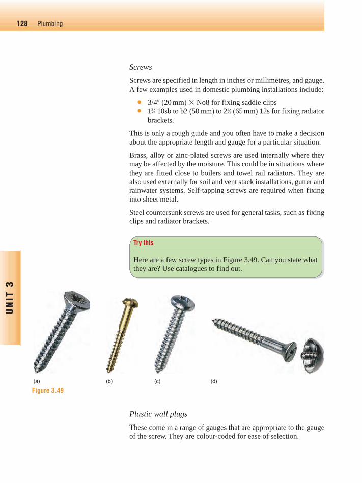
Brass, alloy or zinc-plated screws are used internally where theymay be affected by the moisture. This could be in situations wherethey are fitted close to boilers and towel rail radiators. They arealso used externally for soil and vent stack installations, gutter andrainwater systems. Self-tapping screws are required when fixinginto sheet metal.
Steel countersunk screws are used for general tasks, such as fixingclips and radiator brackets.
128 Plumbing
UN
IT 3
Try this
Here are a few screw types in Figure 3.49. Can you state whatthey are? Use catalogues to find out.
(a) (b) (c) (d)
Figure 3.49
Plastic wall plugs
These come in a range of gauges that are appropriate to the gaugeof the screw. They are colour-coded for ease of selection.
Ch03-H8434.qxd 4/11/07 5:42 PM Page 128
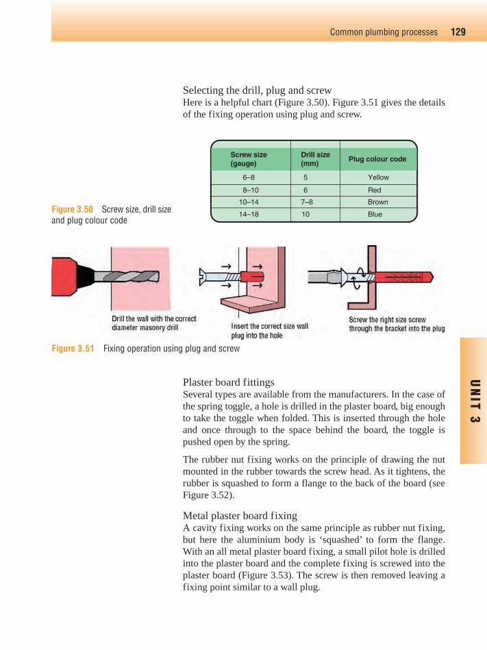
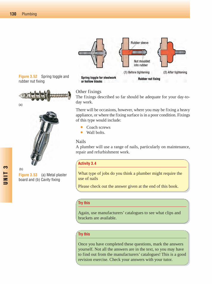
Selecting the drill, plug and screwHere is a helpful chart (Figure 3.50). Figure 3.51 gives the detailsof the fixing operation using plug and screw.
129Common plumbing processes
UN
IT 3
6–8
8–10
10–14 7–8 Brown
14–18 10 Blue
5 Yellow
6 Red
Drill size(mm)
Plug colour code Screw size(gauge)
Figure 3.50 Screw size, drill sizeand plug colour code
Figure 3.51 Fixing operation using plug and screw
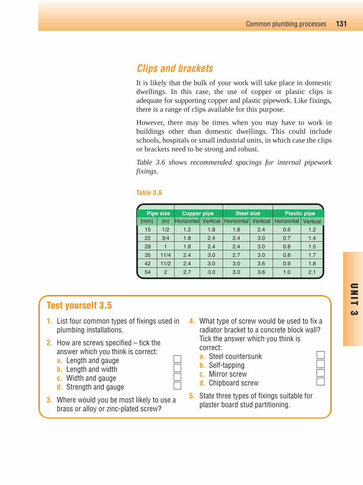
Plaster board fittingsSeveral types are available from the manufacturers. In the case ofthe spring toggle, a hole is drilled in the plaster board, big enoughto take the toggle when folded. This is inserted through the holeand once through to the space behind the board, the toggle ispushed open by the spring.
The rubber nut fixing works on the principle of drawing the nutmounted in the rubber towards the screw head. As it tightens, therubber is squashed to form a flange to the back of the board (seeFigure 3.52).
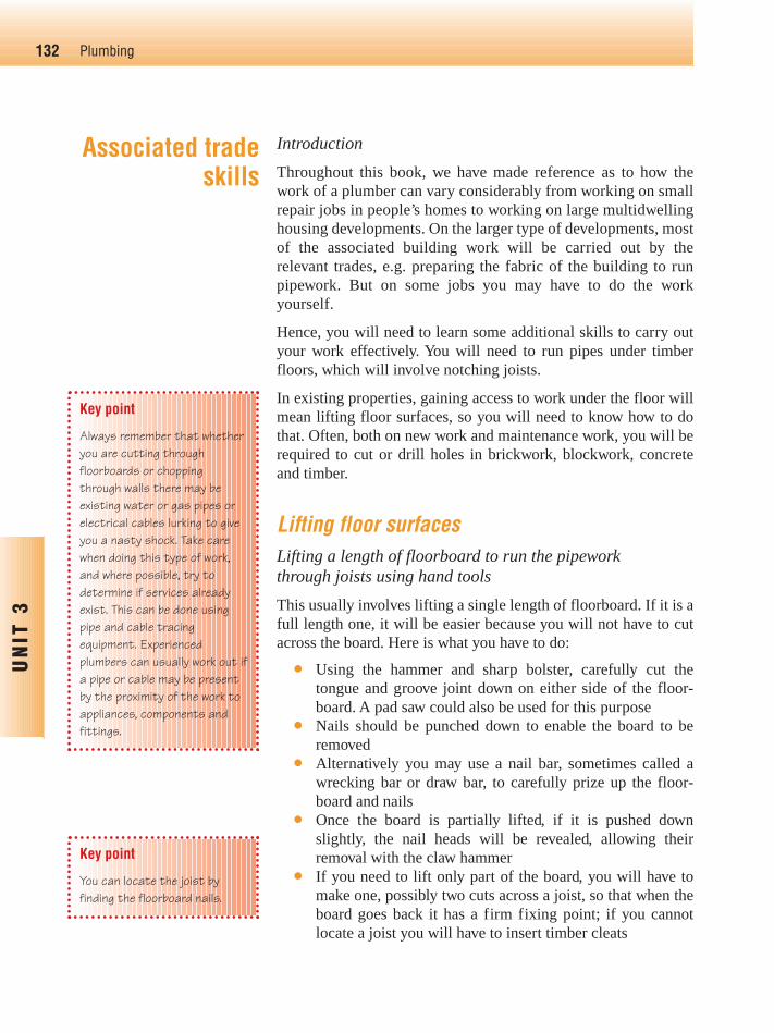
Metal plaster board fixingA cavity fixing works on the same principle as rubber nut fixing,but here the aluminium body is ‘squashed’ to form the flange.With an all metal plaster board fixing, a small pilot hole is drilledinto the plaster board and the complete fixing is screwed into theplaster board (Figure 3.53). The screw is then removed leaving afixing point similar to a wall plug.
Ch03-H8434.qxd 4/11/07 5:42 PM Page 129
130 Plumbing
UN
IT 3
(a)
(b)
Figure 3.53 (a) Metal plasterboard and (b) Cavity fixing
Activity 3.4
What type of jobs do you think a plumber might require theuse of nails
Please check out the answer given at the end of this book.
Try this
Again, use manufacturers’ catalogues to see what clips andbrackets are available.
Try this
Once you have completed these questions, mark the answersyourself. Not all the answers are in the text, so you may haveto find out from the manufacturers’ catalogues! This is a goodrevision exercise. Check your answers with your tutor.
Other fixingsThe fixings described so far should be adequate for your day-to-day work.
There will be occasions, however, where you may be fixing a heavyappliance, or where the fixing surface is in a poor condition. Fixingsof this type would include:
● Coach screws● Wall bolts.
NailsA plumber will use a range of nails, particularly on maintenance,repair and refurbishment work.
Figure 3.52 Spring toggle andrubber nut fixing
Ch03-H8434.qxd 4/11/07 5:42 PM Page 130
131Common plumbing processes
UN
IT 3
1. List four common types of fixings used inplumbing installations.
2. How are screws specified – tick theanswer which you think is correct:a. Length and gaugeb. Length and widthc. Width and gauged. Strength and gauge
3. Where would you be most likely to use abrass or alloy or zinc-plated screw?
4. What type of screw would be used to fix aradiator bracket to a concrete block wall?Tick the answer which you think iscorrect:a. Steel countersunkb. Self-tappingc. Mirror screwd. Chipboard screw
5. State three types of fixings suitable forplaster board stud partitioning.
Test yourself 3.5
Clips and bracketsIt is likely that the bulk of your work will take place in domesticdwellings. In this case, the use of copper or plastic clips is adequate for supporting copper and plastic pipework. Like fixings,there is a range of clips available for this purpose.
However, there may be times when you may have to work inbuildings other than domestic dwellings. This could includeschools, hospitals or small industrial units, in which case the clipsor brackets need to be strong and robust.
Table 3.6 shows recommended spacings for internal pipework fixings.
Pipe size Copper pipe Steel size Plastic pipe (mm) (in) Horizontal Vertical Horizontal Vertical Horizontal Vertical
15 1/2 1.2 1.8 1.8 2.4 0.6 1.2
22 3/4 1.8 2.4 2.4 3.0 0.7 1.4
28 1 1.8 2.4 2.4 3.0 0.8 1.5
35 11/4 2.4 3.0 2.7 3.0 0.8 1.7
42 11/2 2.4 3.0 3.0 3.6 0.9 1.8
54 2 2.7 3.0 3.0 3.6 1.0 2.1
Table 3.6
Ch03-H8434.qxd 4/11/07 5:42 PM Page 131
Introduction
Throughout this book, we have made reference as to how thework of a plumber can vary considerably from working on smallrepair jobs in people’s homes to working on large multidwellinghousing developments. On the larger type of developments, mostof the associated building work will be carried out by therelevant trades, e.g. preparing the fabric of the building to runpipework. But on some jobs you may have to do the workyourself.
Hence, you will need to learn some additional skills to carry outyour work effectively. You will need to run pipes under timberfloors, which will involve notching joists.
In existing properties, gaining access to work under the floor willmean lifting floor surfaces, so you will need to know how to dothat. Often, both on new work and maintenance work, you will berequired to cut or drill holes in brickwork, blockwork, concreteand timber.
Lifting floor surfacesLifting a length of floorboard to run the pipework through joists using hand tools
This usually involves lifting a single length of floorboard. If it is afull length one, it will be easier because you will not have to cutacross the board. Here is what you have to do:
● Using the hammer and sharp bolster, carefully cut thetongue and groove joint down on either side of the floor-board. A pad saw could also be used for this purpose
● Nails should be punched down to enable the board to beremoved
● Alternatively you may use a nail bar, sometimes called awrecking bar or draw bar, to carefully prize up the floor-board and nails
● Once the board is partially lifted, if it is pushed downslightly, the nail heads will be revealed, allowing theirremoval with the claw hammer
● If you need to lift only part of the board, you will have tomake one, possibly two cuts across a joist, so that when theboard goes back it has a firm fixing point; if you cannotlocate a joist you will have to insert timber cleats
132 Plumbing
UN
IT 3
Key point
Always remember that whetheryou are cutting throughfloorboards or choppingthrough walls there may beexisting water or gas pipes orelectrical cables lurking to giveyou a nasty shock. Take carewhen doing this type of work,and where possible, try todetermine if services alreadyexist. This can be done usingpipe and cable tracingequipment. Experiencedplumbers can usually work out ifa pipe or cable may be presentby the proximity of the work toappliances, components andfittings.
Key point
You can locate the joist byfinding the floorboard nails.
Associated tradeskills
Ch03-H8434.qxd 4/11/07 5:42 PM Page 132

● The cross-cuts on the floorboard can be made using anextremely sharp wood chisel or a purpose made floorboardsaw.
Lifting floorboards using power tools
This is done using a circular saw.
The saw can be used to cut down the full length of the tongue andgroove on each side of the board. The cross-cut is made, again overthe joist, making sure that the blade does not hit the nails. Settingthe saw blade at a slight angle will help to avoid hitting the nails.
Cutting traps in floorboards
This uses similar methods like removing a single floorboard,either using hand or power tools. It is just that there are moreboards to cut, although in shorter lengths in order to make anaccess point to a section of pipe or component such as a centralheating pump.
Replacing floorboards and traps
The floorboard lengths and traps should be screwed back intoposition to make future inspection or maintenance easier, thisshould be done using countersunk wood screws. When refixedover the pipework, the board surface should be marked accord-ingly, e.g. water, heating or gas pipework.
Where it has not been possible to find a joist to refit the board ortrap, cleats must be used to support the board end. The followingillustration (Figure 3.54) shows a trap or board replacement overjoists and using cleats.
133Common plumbing processes
UN
IT 3
Key point
Do not forget the informationwe provided earlier in the unitabout the safe use of powertools.
Figure 3.54 Trap or boardreplacement over joists and usingcleats
Ch03-H8434.qxd 4/11/07 5:42 PM Page 133
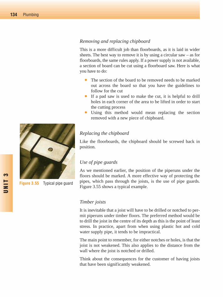
Removing and replacing chipboard
This is a more difficult job than floorboards, as it is laid in widersheets. The best way to remove it is by using a circular saw – as forfloorboards, the same rules apply. If a power supply is not available,a section of board can be cut using a floorboard saw. Here is whatyou have to do:
● The section of the board to be removed needs to be markedout across the board so that you have the guidelines tofollow for the cut
● If a pad saw is used to make the cut, it is helpful to drillholes in each corner of the area to be lifted in order to startthe cutting process
● Using this method would mean replacing the sectionremoved with a new piece of chipboard.
Replacing the chipboard
Like the floorboards, the chipboard should be screwed back inposition.
Use of pipe guards
As we mentioned earlier, the position of the piperuns under thefloors should be marked. A more effective way of protecting thepipes, which pass through the joists, is the use of pipe guards.Figure 3.55 shows a typical example.
Timber joists
It is inevitable that a joist will have to be drilled or notched to per-mit piperuns under timber floors. The preferred method would beto drill the joist in the centre of its depth as this is the point of leaststress. In practice, apart from when using plastic hot and coldwater supply pipe, it tends to be impractical.
The main point to remember, for either notches or holes, is that thejoist is not weakened. This also applies to the distance from thewall where the joist is notched or drilled.
Think about the consequences for the customer of having joiststhat have been significantly weakened.
134 Plumbing
UN
IT 3
Figure 3.55 Typical pipe guard
Ch03-H8434.qxd 4/11/07 5:42 PM Page 134

Building Regulations in practice
Worked out example
For a joist 200 mm deep and 2.5 m long, any notch must have amaximum depth of D � 8. So the depth of the notch is 200 � 8 �25 mm. The minimum length is 7 � 2500 � 100 � 175 mm. Themaximum length is L � 4 from its bearing, so maximum length of2500 � 4 � 625 mm.
The joists are normally cut using a hand or floorboard saw. Theyare cut to the required depth and width, and the timber notch isremoved using a hammer and a sharp wood chisel.
The width of the notch should be large enough to give freedom ofmovement, in order to allow expansion and contraction, particu-larly for hot water supply pipework.
135Common plumbing processes
UN
IT 3
Activity 3.5
Which Building Regulation covers the notching and drillingof joists?
Check out the Building Regulations at www.odpm.gov.uk andthen check your answer with the one at the end of the unit.
Centre of bearing
Centre of bearing
Depth ‘D’
Depth of notch not more
than 1/8 D
Notch in this partof the joist only
Notches
Span ‘S’
0.07 � S
8/4
Figure 3.56
The Building Regulations set out the requirement for notching ordrilling joists.
Ch03-H8434.qxd 4/11/07 5:42 PM Page 135
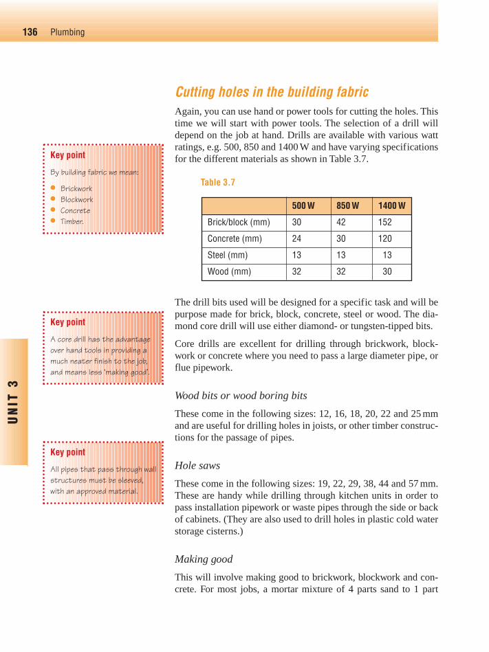
Cutting holes in the building fabricAgain, you can use hand or power tools for cutting the holes. Thistime we will start with power tools. The selection of a drill willdepend on the job at hand. Drills are available with various wattratings, e.g. 500, 850 and 1400 W and have varying specificationsfor the different materials as shown in Table 3.7.
The drill bits used will be designed for a specific task and will bepurpose made for brick, block, concrete, steel or wood. The dia-mond core drill will use either diamond- or tungsten-tipped bits.
Core drills are excellent for drilling through brickwork, block-work or concrete where you need to pass a large diameter pipe, orflue pipework.
Wood bits or wood boring bits
These come in the following sizes: 12, 16, 18, 20, 22 and 25 mmand are useful for drilling holes in joists, or other timber construc-tions for the passage of pipes.
Hole saws
These come in the following sizes: 19, 22, 29, 38, 44 and 57 mm.These are handy while drilling through kitchen units in order topass installation pipework or waste pipes through the side or backof cabinets. (They are also used to drill holes in plastic cold waterstorage cisterns.)
Making good
This will involve making good to brickwork, blockwork and con-crete. For most jobs, a mortar mixture of 4 parts sand to 1 part
136 Plumbing
UN
IT 3
Key point
By building fabric we mean:
● Brickwork● Blockwork● Concrete● Timber.
Key point
A core drill has the advantageover hand tools in providing amuch neater finish to the job,and means less ‘making good’.
Key point
All pipes that pass through wallstructures must be sleeved,with an approved material.
500 W 850 W 1400 W
Brick/block (mm) 30 42 152
Concrete (mm) 24 30 120
Steel (mm) 13 13 13
Wood (mm) 32 32 30
Table 3.7
Ch03-H8434.qxd 4/11/07 5:42 PM Page 136
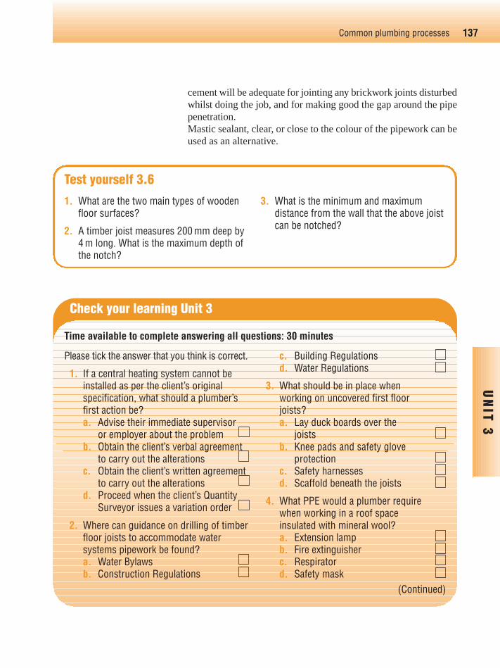
137Common plumbing processes
UN
IT 3
1. What are the two main types of woodenfloor surfaces?
2. A timber joist measures 200 mm deep by4 m long. What is the maximum depth ofthe notch?
3. What is the minimum and maximumdistance from the wall that the above joistcan be notched?
Test yourself 3.6
cement will be adequate for jointing any brickwork joints disturbedwhilst doing the job, and for making good the gap around the pipepenetration.Mastic sealant, clear, or close to the colour of the pipework can beused as an alternative.
Please tick the answer that you think is correct.
1. If a central heating system cannot beinstalled as per the client’s originalspecification, what should a plumber’sfirst action be?a. Advise their immediate supervisor
or employer about the problemb. Obtain the client’s verbal agreement
to carry out the alterationsc. Obtain the client’s written agreement
to carry out the alterationsd. Proceed when the client’s Quantity
Surveyor issues a variation order
2. Where can guidance on drilling of timberfloor joists to accommodate watersystems pipework be found?a. Water Bylawsb. Construction Regulations
c. Building Regulationsd. Water Regulations
3. What should be in place when working on uncovered first floor joists?a. Lay duck boards over the
joistsb. Knee pads and safety glove
protectionc. Safety harnessesd. Scaffold beneath the joists
4. What PPE would a plumber require when working in a roof space insulated with mineral wool?a. Extension lampb. Fire extinguisherc. Respiratord. Safety mask
Check your learning Unit 3
Time available to complete answering all questions: 30 minutes
(Continued)
Ch03-H8434.qxd 4/11/07 5:42 PM Page 137

138 Plumbing
UN
IT 3
5. What is the statutory requirement forcutting the depth of notches in timberfloor joists, where D � Depth?a. 1⁄8 th Db. 1⁄6 th Dc. 1⁄4 th Dd. 1⁄10 th D
6. What information should be left with the customer after installation of a newboiler?a. DIY servicing informationb. Boiler installation templatec. Material delivery noted. User instructions
7. What is provided with materials toconfirm the number and type of itemsdelivered?a. Materials scheduleb. Materials invoicec. Delivery advice noted. Copy of the order
8. On a large multidwelling building site the progress of other trades can be checked by referring to the:a. Bill of Quantitiesb. Work programmec. Materials scheduled. Site plan
9. Upon delivery of sanitary ware to thesite, the plumber should first check if it is:a. Adequately protectedb. Water regulation approvedc. The correct specificationd. Free from damage/defects
10. What action should a plumber take if a fault on a gas meter is suspected?a. Advise the customerb. Repair the faultc. Contact the gas supplierd. Turn off the supply
11. When jointing copper tube, the purpose of the grab ring on a push-fit plastic fitting is to:a. Prevent the pipe damaging the
‘O’ ringb. Ensure the pipe is locked in
placec. Ensure the fitting is watertightd. Prevent the pipe from flattening
12. Sleeves must be provided when a pipe:a. Is located in the roof spaceb. Comes into contact with leadc. Passes through a brick walld. Is laid in timber floor joists
13. For what type of fitting would theapplication of solder wire during thejointing process be required?a. Integral ringb. Capillaryc. Type Ad. Type B
14. What grade of copper tube is best suited to being bent using an internalbending spring?a. X (R250)b. Y (R220/250)c. Zd. W
Check your learning Unit 3 (Continued)
Ch03-H8434.qxd 4/11/07 5:42 PM Page 138

15. What piece of equipment would be themost appropriate for bending 20 mm lowcarbon steel pipe?a. External bending springb. Stand benderc. Hydraulic press benderd. Internal bending spring
16. On which tool is ‘mushrooming’ mostlikely to occur?a. Wood chiselb. Screw driverc. Cold chiseld. Claw hammer
17. What document would be needed whenmaintaining a water softener?a. Maintenance scheduleb. Installation programmec. Manufactures’ catalogued. Manufacturers’ instructions
18. What type of document would be usedto plan the work activities on a long-termmaintenance contract?a. Bill of Quantitiesb. Programme
c. Materials scheduled. Installation plan
19. On a job to replace a bathroom suite in aone bathroom occupied dwelling, whichof the following should a plumber installfirst in order to minimise disruption tothe customer?a. Bidetb. WC suitec. Shower trayd. Bath
20. What information should be issued to acustomer upon completion of a long-term planned maintenance contract?a. Bill of Quantitiesb. Material invoicesc. Maintenance recordsd. Maintenance programme
139Common plumbing processes
UN
IT 3
Check your learning Unit 3 (Continued)
Ch03-H8434.qxd 4/11/07 5:42 PM Page 139

140 Plumbing
UN
IT 3
Sources of InformationWe have included references to information sources at the relevant points in the text; here are someadditional contacts that may be helpful.
● Pegler LimitedSt Catherine’s AvenueDoncasterSouth YorkshireDN4 8DF
Tel: 01302 560560Website:www.pegler.co.uk
● Yorkshire FittingsHead OfficePO Box 66LeedsLS10 1NATel: 0113 270 1104e-mail: [email protected]:www.yorkshirefittings.co.uk
● Copper Development AssociationGrovelands Business CentreBoundary WayHemel HempsteadHerts HP2 7TEUnited KingdomTel: 01442 275700e-mail: [email protected]:www.cda.org.uk(CDA provides some excellent generalinformation on copper tube)
● Hepworth Plumbing ProductsHead OfficeEdlington LaneEdlingtonDoncasterDN12 1BYTel: 01709 856400Website:www.hepworthplumbing.co.uk
● ScrewfixScrewfix DirectFREEPOSTYeovilBA22 8BFTel: 0500 41 41 41e-mail: [email protected]:www.screwfix.com
● Draper Tools LtdHursley RoadChandler’s FordEastleighHantsSO53 1YFTel: 023 8026 6355e-mail: [email protected]:www.draper.co.uk
● Ridgid ToolArden Place HousePrixmore AvenueLetchworthHertsSG6 1LHTel: 01462 485335e-mail: [email protected]
● Water Regulations Advisory SchemeFern ClosePen-Y-Fan Industrial EstateOakdaleGwentNP11 3EHTel: 01495 248454e-mail: [email protected]:www.wras.co.uk
You may also find the following websites useful: www.piping.georgfischer.com, www.plumbworld.co.uk
Ch03-H8434.qxd 4/11/07 5:42 PM Page 140


![Welcome [booksite.elsevier.com]booksite.elsevier.com/9780123745149/appendices/CD-ROM_Menu_Bo… · Welcome to the Programming Language Pragmatics, ... Scopes, and BindingsNa ... 8.2.2](https://img.dokumen.tips/doc/110x75/5aa6559c7f8b9ae7438ea65f/welcome-welcome-to-the-programming-language-pragmatics-scopes-and-bindingsna.jpg)


![[American Society of Plumbing Engineers] Plumbing](https://img.dokumen.tips/doc/110x75/577cb1c91a28aba7118bddeb/american-society-of-plumbing-engineers-plumbing.jpg)