Embed Size (px)
Citation preview

6000 SERIESFORWARD MOUNT
ZTR® MOWERS
Operator's Manual
2001

Page 2
IMPORTANT - READ CAREFULLY
The Dixon® ZTR® Mower is both easy and fun to operate. However, any power
mower must be operated properly to be safe. It is not a toy or a recreational vehicle.Before you start to use the mower, read the operator's manual carefully and becomecompletely familiar with the controls.
The information in this operator's manual applies to all Dixon® ZTR® 6000 Series
Commercial Mowers. Your Dixon dealer will gladly answer any questions.
See your dealer for warranty service, parts and repairs.
DIXON INDUSTRIES, INC.A BLOUNT International Inc. Co.PO BOX 1569COFFEYVILLE KS 67337 0945316 251 2000

Page 3
INDEX
SAFETY ..................................................................Pages 4-9WARRANTY POLICY............................................Page 10SPECIFICATIONS .................................................Page 11SEAT ADJUSTMENT INSTRUCTIONS............. Page 12CONTROLS ...........................................................Pages 13-16OPERATION INSTRUCTIONS ...........................Pages 17-21CARE AND MAINTENANCE ...............................Pages 22-34STANDARD SERVICE PARTS LIST .....................Page 35TROUBLESHOOTING .........................................Pages 36-37
6000 Series Forward MountPart No. 13090-0700

Page 4
...read and understand this manual to prevent injuries.
RIDING LAWNMOWERS, IF IMPROPERLY OPERATED,CAN CAUSE SERIOUS INJURY OR DEATH
The most common causes of injury to the operator or bystander...
SAFETY
BLADE CONTACT TIP-OVER
BACK-OVERRUNOVER

Page 5
SAFETY SYMBOLS
Safety Alert Symbol
When you see this symbol,
BE ALERT to the potential for injury.
Follow recommended safety precautions and safe operatingpractices.
Dangerindicates an imminently hazardous situation which,if not avoided, will result in death or serious injury.
Warningindicates a potentially hazardous situation which, ifnot avoided, could result in death or serious injury.
Cautionindicates a potentially hazardous situation which, if
not avoided, may result in minor or moderate injury.It may also be used to alert against unsafe practices.
SAFETY

Page 6
GENERAL OPERATION:
• Read, understand, and follow all instructions in the manual and on the mower before starting.
• Only allow responsible adults, who are familiar with the instructions, to operate the mower.
• Clear the area of objects such as rocks, toys, wire, etc., which could be picked up and thrown by the blade.
• Be sure the area is clear of other people before mowing. Stop mower if anyone enters the area.
• Never carry passengers.
• Do not mow in reverse unless absolutely necessary. Always look down and behind before and whilebacking.
• Be aware of the mower discharge direction and do not point it at anyone. Do not operate the mowerwithout either the entire grass catcher or the deflector in place.
• Slow down before turning.
• Never leave a running mower unattended. Always turn off blades, set parking brake, stop engine, andremove key before dismounting.
• Turn off blades when not mowing.
• Stop engine before removing grass catcher or unclogging chute.
• Mow only in daylight or good artificial light.
• Do not operate the mower while under the influence of alcohol or drugs.
• Watch for traffic when operating near or crossing roadways.
• Use extra care when loading or unloading the mower into a trailer or truck. Do not ride the mower whenloading & unloading.
• Always wear safety goggles or safety glasses with side shields when operating mower.
• Data indicates that operators, age 60 years and above, are involved in a large percentage of riding mower-related injuries. These operators should evaluate their ability to operate the riding mower safely enoughto protect themselves and others from serious injury.
• Follow the manufacturer's recommendation for wheel weights or counterweights.
• Maintain or replace safety and instruction labels, as necessary.
WARNING: The engine exhaust from this product contains chemicals known to the State of California to cause cancer, birth defects or other reproductive harm.
This cutting mower is capable of amputating hands & feet,and throwing objects.
Failure to observe the following safety instructions could result inserious injury or death.
SAFETY

Page 7
SAFETY
SLOPE OPERATION:
Slopes are a major factor related to loss-of-control and tip-over accidents, which can result in severe injury or death.
All slopes require extra caution.
If you cannot back up the slope or if you feel uneasy on it, do not mow it!
DO
Mow across the slope with your Dixon ZTR - never up or down.
Remove obstacles such as rocks, tree limbs, etc.
Watch for holes, ruts or bumps. Uneven terrain could overturn the mower. Tall grass can hideobstacles.
Use slow speed. Tires may lose traction on slopes even though the brakes are functioning properly.
Use extra care with grass catchers or other attachments. These can change the stability of the mower.
Keep all movement on the slopes slow and gradual. Do not make sudden changes in speed ordirection.
Avoid starting or stopping on a slope. If tires lose traction, disengage the blades and proceed slowlydown the slope.
If front wheels lift off the ground, pull the levers back to stabilize the mower.
DO NOT
Do not turn on slopes unless necessary, and then, turn slowly and gradually downhill, if possible.
Do not mow near drop-offs, ditches, or embankments. The mower could suddenly turn over if awheel is over the edge of a cliff or ditch, or if an edge caves in.
Do not mow on wet grass. Reduced traction could cause sliding.
Do not try to stabilize the mower by putting your foot on the ground.
Do not use grass catcher on steep slopes.

Page 8
SAFETY
Tragic accidents can occur if the operator is not alert to thepresence of children.
Children are attracted to lawn mowers and the mowing activity.
NEVER assume children will stay where they were last seen.
Be alert to avoid accidents.
• Keep children out of the mowing area and under the watchful care of anotherresponsible adult.
• Be alert and turn mower off if a child enters the area.
• Before and during backing, look behind and DOWN for small children.
• Never carry children. They may fall off and be seriously injured or interfere withsafe mower operation.
• Never allow children to operate the mower.
• Use extra care when approaching blind corners, shrubs, trees, or other objects thatmay obscure vision.
CHILDREN:
Page 9
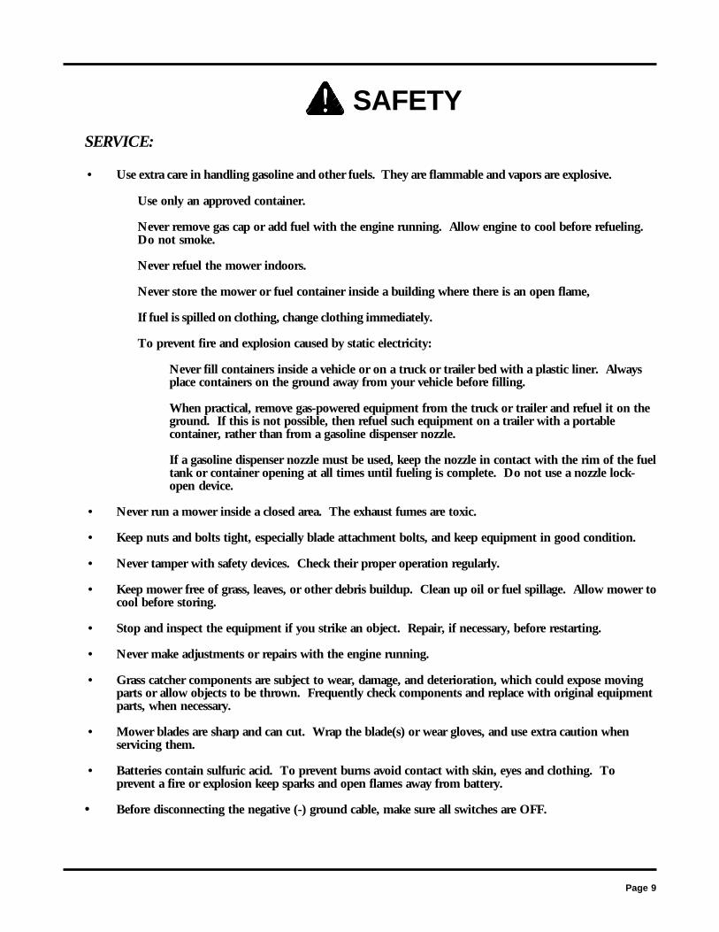
SAFETYSERVICE:
• Use extra care in handling gasoline and other fuels. They are flammable and vapors are explosive.
Use only an approved container.
Never remove gas cap or add fuel with the engine running. Allow engine to cool before refueling.Do not smoke.
Never refuel the mower indoors.
Never store the mower or fuel container inside a building where there is an open flame,
If fuel is spilled on clothing, change clothing immediately.
To prevent fire and explosion caused by static electricity:
Never fill containers inside a vehicle or on a truck or trailer bed with a plastic liner. Alwaysplace containers on the ground away from your vehicle before filling.
When practical, remove gas-powered equipment from the truck or trailer and refuel it on theground. If this is not possible, then refuel such equipment on a trailer with a portablecontainer, rather than from a gasoline dispenser nozzle.
If a gasoline dispenser nozzle must be used, keep the nozzle in contact with the rim of the fueltank or container opening at all times until fueling is complete. Do not use a nozzle lock-open device.
• Never run a mower inside a closed area. The exhaust fumes are toxic.
• Keep nuts and bolts tight, especially blade attachment bolts, and keep equipment in good condition.
• Never tamper with safety devices. Check their proper operation regularly.
• Keep mower free of grass, leaves, or other debris buildup. Clean up oil or fuel spillage. Allow mower tocool before storing.
• Stop and inspect the equipment if you strike an object. Repair, if necessary, before restarting.
• Never make adjustments or repairs with the engine running.
• Grass catcher components are subject to wear, damage, and deterioration, which could expose movingparts or allow objects to be thrown. Frequently check components and replace with original equipmentparts, when necessary.
• Mower blades are sharp and can cut. Wrap the blade(s) or wear gloves, and use extra caution whenservicing them.
• Batteries contain sulfuric acid. To prevent burns avoid contact with skin, eyes and clothing. Toprevent a fire or explosion keep sparks and open flames away from battery.
• Before disconnecting the negative (-) ground cable, make sure all switches are OFF.
Page 10
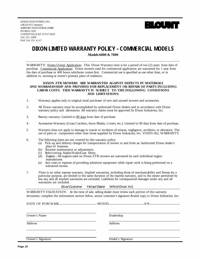
DIXON INDUSTRIES, INC.a BLOUNT companyAIRPORT INDUSTRIAL PARKPO BOX 1569COFFEYVILLE KS 67337 0945316 251 2000FAX 316 251 4117
DIXON LIMITED WARRANTY POLICY - COMMERCIAL MODELSModels 6000 & 7000
WARRANTY: Home Owner Application: This Dixon Warranty term is for a period of two (2) years from date ofpurchase. Commercial Application: Dixon mowers used for commercial application are warranted for 1 year fromthe date of purchase or 400 hours whichever comes first. Commercial use is specified as use other than, or inaddition to, mowing at owner's primary place of residence.
DIXON ZTR MOWERS ARE WARRANTED AGAINST DEFECTS IN MATERIALSAND WORKMANSHIP AND PROVIDES FOR REPLACEMENT OR REPAIR OF PARTS INCLUDING
LABOR COSTS. THIS WARRANTY IS SUBJECT TO THE FOLLOWING CONDITIONSAND LIMITATIONS:
1. Warranty applies only to original retail purchaser of new and unused mowers and accessories.
2. All Dixon warranty must be accomplished by authorized Dixon dealers and in accordance with Dixonwarranty policy and allowances. All warranty claims must be approved by Dixon Industries, Inc.
3. Battery warranty: Limited to 90 days from date of purchase.
4. Accessories Warranty (Grass Catchers, Snow Blades, Covers, etc.): Limited to 90 days from date of purchase.
5 Warranty does not apply to damage in transit or incidents of misuse, negligence, accidents, or alteration. Theuse of parts or components other than those supplied by Dixon Industries, Inc. VOIDS ALL WARRANTY.
6. The following items are not covered by this warranty policy:(a) Pick up and delivery charges for transportation of mower to and from an Authorized Dixon dealer's place of business.(b) Routine maintenance or adjustments.(c) Belts/cutting blades/HydroGear filters.(d) Engines -- All engines used on Dixon ZTR mowers are warranted by each individual engine manufacturer.(e) Any costs or expense of providing substitute equipment while repair work is being performed on a warranted mower.
7. There is no other express warranty. Implied warranties, including those of merchantability and fitness for aparticular purpose, are limited to the same duration of the express warranty, and to the extent permitted bylaw any and all implied warranties are excluded. Liabilities for consequential damages under any and allwarranties are excluded.
Blue/Customer Yellow/Dealer White/Dixon Ind.WARRANTY VALIDATION: At the time of sale, selling dealer must review each portion of this warrantydocument, complete the information section below, secure customer's signature &send copy to Dixon Industries, Inc.
DATE OF PURCHASE MODEL S/N
Owner's Name Dealership
Address Address
Owner's Signature Dealer's Signature
Page 11
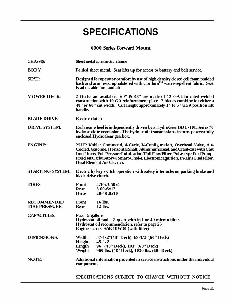
CHASSIS: Sheet metal construction frame
BODY: Folded sheet metal. Seat lifts up for access to battery and belt service.
SEAT: Designed for operator comfort by use of high density closed cell foam paddedback and arm rests, upholstered with CorduraTM water-repellent fabric. Seatis adjustable fore and aft.
MOWER DECK: 2 Decks are available. 60" & 48" are made of 12 GA fabricated weldedconstruction with 10 GA reinforcement plate. 3 blades combine for either a48" or 60" cut width. Cut height approximately 1" to 5" via 9 position lifthandle.
BLADE DRIVE: Electric clutch
DRIVE SYSTEM: Each rear wheel is independently driven by a HydroGear BDU-10L Series 70hydrostatic transmission. The hydrostatic transmissions, in turn, power a fullyenclosed HydroGear gearbox.
ENGINE: 25HP Kohler Command, 4-Cycle, V-Configuration, Overhead Valve, Air-Cooled, Gasoline, Horizontal Shaft, Aluminum Head, and Crankcase with CastIron Liners, Full Pressure Lubrication/Full Flow Filter, Pulse-type Fuel Pump,Fixed Jet Carburetor w/Smart-Choke, Electronic Ignition, In-Line Fuel Filter,Dual Element Air Cleaner.
STARTING SYSTEM: Electric by key switch operation with safety interlocks on parking brake andblade drive clutch.
TIRES: Front 4.10x3.50x4Rear 5.00-6x13Drive 20-10.0x10
RECOMMENDED Front 16 lbs.TIRE PRESSURE: Rear 12 lbs.
CAPACITIES: Fuel - 5 gallonsHydrostat oil tank - 3 quart with in-line 40 micron filterHydrostat oil recommendation, refer to page 25Engine - 2 qts. SAE 10W30 (with filter)
DIMENSIONS: Width 57-1/2”(48" Deck), 69-1/2"(60" Deck)Height 45-1/2"Length 96" (48” Deck), 101” (60” Deck)Weight 960 lbs. (48" Deck), 1030 lbs. (60" Deck)
NOTE: Additional information provided in service instructions under the individualcomponent.
SPECIFICATIONS SUBJECT TO CHANGE WITHOUT NOTICE
SPECIFICATIONS
6000 Series Forward Mount

Page 12
SEAT ADJUSTMENTINSTRUCTIONS
6000 Series
1. Grasp seat slide adjuster and move it into adjustment position.
2. Slide seat forward or backward.
3. Release seat slide adjuster.
Page 13
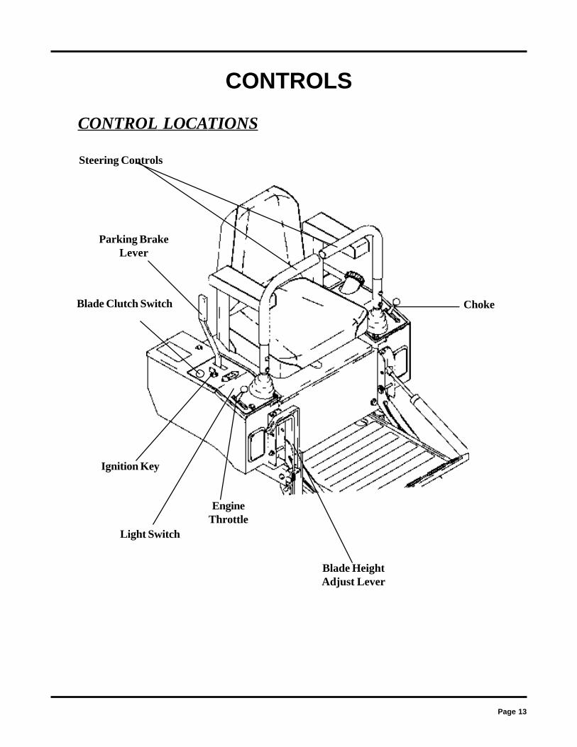
CONTROLS
CONTROL LOCATIONS
Ignition Key
Steering Controls
Parking BrakeLever
Blade Clutch Switch
Light Switch
EngineThrottle
Choke
Blade HeightAdjust Lever

Page 14
CONTROLSPARKING BRAKE:
The parking brake is designed to hold the mower from moving and is notintended for use in stopping the mower while it is in motion.
TO SET PARKING BRAKE:
The hand operated parking brake is located at right hand sideof mower.
To engage brake, pull rearward.
To release brake, move lever forward.
NOTE: Always set parking brake before dismounting.
Release parking brake before moving mower.
HYDRO-GEAR DRIVE SYSTEM:
Allows the mower to turn on its own axis (zero turning radius).
Each lever controls one side of the mower.
NOTE: The pressure required to operate the mower is very light.
CAUTION Engage parking brake before starting engine

Page 15
CONTROLS
TO GO FORWARD:From neutral position, gently push both drive levers forward.
To increase speed, move levers farther forward.
TO GO BACKWARD:
From neutral position, gently pull both drive levers toward you.
TURNING:Turning is controlled by moving one drive lever slightly forward or rearward of the other.
To turn left, move left lever rearward of the right lever.
To turn "square corners" move lever of desired direction to neutral.
To turn on mower's own axis (zero turning radius) stop and move one lever to reverse positionand the other to forward position.
BRAKING:To brake mower, move both levers in direction opposite of travel, release levers to neutral, setparking brake. Park only on level surfaces.
CHOKE CONTROL LEVER:Located on control panel to operator's left.
Used to start a cold engine.
THROTTLE CONTROL LEVER:
Located on control panel to operator's right.
Controls engine speed, slow to maximum.
While mowing, throttle control should be set to the MAXIMUM or wide open setting to insureadequate cooling of the engine and to maintain mower deck blade speed.
(LEFT TURN OPPOSITE)

Page 16
CONTROLS
BLADE DRIVE:
Located on the control panel to the operator's right.
To engage blades pull switch up.
To disengage blades push switch down.
CIRCUIT BREAKER:
Located on the control panel to the operator's right.
Protection of the electrical system is by (2) 30 amp circuit breakers.If circuit breaker trips, push button to reset.If this condition repeats, consult dealer for inspection and repair.
MOWER DECK CUT HEIGHT LIFT LEVER:
Located to the right and front of the operator.
Controls the cutting height.
Nine positions of adjustment.
Depress trigger and move lever forward to lower deck.
Depress trigger and pull lever back to raise deck.
NOTE: To achieve a 1" to 3" cutting range, the bar connecting the deck lift handle and the rearof the deck must be in the first hole. To achieve a 3" to 5" range, the bar connecting the deck lifthandle and the rear of the deck must be in the second hole.
NOTE: Always use high position for transport.
Page 17
OPERATION INSTRUCTIONS
The safe and successful operation of the 6000 Series will depend upon the operator having the correctknowledge of all controls used on the mower and making good judgements about the terrain to be mowed.
NEVER allow anyone to operate the mower without complete knowledge of all controls and theirfunctions.
During initial operation, "learning to drive", set throttle at slow speed.
Sound judgement by the owner will prevent accidents.
TOWING
Towing a trailer or other attachment that is too heavy could damage the drive or cause themower to become unstable. Limit loads to 500 pounds or less on this mower.
BEFORE OPERATING MOWER
1. Read engine manufacturer's operating and maintenance instructions.
2. Discuss proper maintenance with your dealer.
3. Read and observe all safety instructions on your mower and in themanual.
4. Check engine oil.
5. Check gas cap to be sure it is in place.
6. Be sure parking brake is on.
7. Mower blade drive is off.
8. Know how to stop engine. (Turn key to off position)

Page 18
OPERATION INSTRUCTIONS
TESTING OF SAFETY INTERLOCK SYSTEMS:
PARKING BRAKE SWITCH TEST: With parking brake in the ON position,start the engine. With the enginerunning, pull one control lever out of theneutral position. The engine shouldstop. Repeat for the other control lever,then repeat pulling both control leversout of neutral at the same time. In allcases the engine should stop.
BLADE DRIVE SWITCH TEST: (Electric Clutch or Manual Drive)
a. With either electric blade drive switchturned on, or manual lever turned forward,parking brake in On position, engineshould not turn over or attempt to startwhen key switch is moved to the startposition.
b. In a SAFE AREA away from bystanders,start the engine, place throttle setting atmaximum or full. Engage the blade driveeither through the electric clutch switch orby turning the manual lever forward.Raise weight slightly off of seat. Engineshould stop.
c. If any Safety Check fails, do not operatethe mower until the system has beenchecked and repaired by an AuthorizedDixon ZTR Dealer.

Page 19
OPERATION INSTRUCTIONS
STARTING INSTRUCTIONS: Cold Engine
1. Push choke control lever fully forward.
2. Push throttle control lever to 1/2 setting.
3. Insert ignition key and turn to "Start" position. When engine starts,release ignition key. Key will return to "Run" position.
4. Once engine starts to warm up, slowly move choke control lever to thefully closed position.
5. Move throttle control lever to the wide open or maximum setting for actualoperation of the mower deck.
6. Engine must be operated at wide open or maximum setting to insureadequate lubrication, cooling and cut quality of the mower deck.
Note: 6000 Series mowers will require a slightly longer warm-up period usingpartial choke settings.
UNLOCK TRANSMISSION:
The freewheel levers are located oneach side of the mower below the seatmount (flip up the foot deck to accessthem). Lift the levers slightly, pushthem to the rear and down to releasethe transmissions for free wheeling. Toengage the transmissions lift the leversslightly, pull them forward and thendown.
NOTE: The tractor should never bepulled at more than 2 miles per hour orfor any appreciable distance.
Page 20
STARTING INSTRUCTIONS: Engine has been operated.
1. Move throttle control lever to 1/4 to 1/2 setting.
2. Insert ignition key and turn to "Start" position. When engine starts,release ignition key. Key will return to "Run" position.
3. Move throttle control lever to wide open or maximum setting for actualoperation of the mower deck.
NOTE: Model ZTR 6025 may require partial choke setting to start evenif the engine has been operated for a period of time.
4. Engine must be operated at wide open or maximum setting to insureadequate lubrication, cooling and cut quality of the mower deck.
DO NOT operate the engine in an enclosed area due to theharmful exhaust gas produced.
NOTE: On initial operation, set throttle at slow speed.
Engine cannot be restarted when blade is engaged.
Safety switches stop engine when operator leaves seat whilemower blade is engaged.
Always turn engine off when leaving mower.
OPERATION INSTRUCTIONS
CAUTION

Page 21
In order to achieve optimum cutting performance, please read and follow the tips listed below.
Additional information can be found in the troubleshooting guide on pages 36-37.
Be sure that deflector is properly installed on thedischarge chute.
1. Set engine speed control to the wide open or full setting.
2. Do Not Attempt To Cut Grass When It Is Wet. Wet grass will clog the underside of the deckand discharge area.
3. If the grass is tall, place the mower deck cut height lever in the top or second notch. "Initially"overlap cutting swaths instead of a full swath with each pass. Some applications may requirea second cutting.
4. Keep The Underside Of The Mower Deck Clean. Frequent removal of dried grass and dirt willallow the clippings to discharge correctly.
5. Maintain sharp blade(s) throughout the cutting season.
OPERATION INSTRUCTIONS
GRASS HEIGHT SUGGESTIONS:
Correct mowing height can reduce weeds and disease by 50% to 80%
The following grass cut heights are based on adequate moisture conditions and normal thatchbuildup in a healthy lawn. Some locations and applications may require slightly different cutheights. If in doubt, consult your local lawn professional for assistance.
Grass Types: Best Cut Heights:
Zoysia 2" - 2 1/2"Blue Grass 1 1/2" - 3"Fescue Blends 1 1/2" - 3"St. Augustine (Mid South) 1 1/2" - 2"St. Augustine (Deep South) 3" - 4"Tifton Bermuda 1 1/2"Centipede 1 1/2" - 2"Common Bermuda 1 1/2" - 2"Bahia/Argentina/Pensacola 2"
CAUTION

Page 22
CARE AND MAINTENANCE
MAINTENANCE SCHEDULECheck drive belts . . . . . . . . . . . . . . . . . . . . . . . every 50 hours
(20 hours break-in)Check crankcase oil level. . . . . . . . . . . . . . . . . . .before each useClean grass from Hydrostat fans and cooling fans . . . . . .before each useCheck air intake screen. . . . . . . . . . . . . . . . . . . . . after each useClean grass under deck . . . . . . . . . . . . . . . . . . . . after each useCheck tire pressure . . . . . . . . . . . . . . . . . . . . . . every 10 hoursCheck battery fluid . . . . . . . . . . . . . . . . . . . . . . every 10 hoursSharpen mower blades . . . . . . . . . . . . . . . . . . . . every 10 hoursCheck air filter element . . . . . . . . . . . . . . . . . . . . every 25 hoursCheck hydrostatic transmission fluid . . . . . . . . . . . . . every 25 hoursService engine air filter pre-cleaner . . . . . . . . . . . . . . every 25 hoursGrease driveline (3 fittings) . . . . . . . . . . . . . . . . . . every 50 hoursGrease jack shaft . . . . . . . . . . . . . . . . . . . . . . . every 50 hoursGrease deck pivot tube . . . . . . . . . . . . . . . . . . . .every 50 hoursCheck adjustment of P.T.O. clutch. . . . . . . . . . . . . . .every 50 hours
(or if blades do not stop with 7 seconds from switch disengagement)
Service air filter element . . . . . . . . . . . . . . . . . . . .every 25 hoursChange engine crankcase oil. . . . . . . . . . . . . . . . .every 100 hours
(5 hours break-in)Change engine oil filter. . . . . . . . . . . . . . . . . . . . every 100 hoursChange hydrostat oil filter (7252) . . . . . . . . . . . . . . every 500 hours
(50 hours break-in)Change oil in deck gearbox . . . . . . . . . . . annually or every 500 hoursReplace air filter element. . . . . . . . . . . . . . . . . . . every 100 hoursCheck spark plugs. . . . . . . . . . . . . . . . annually or every 200 hoursService battery . . . . . . . . . . . . . . . . . . annually or every 500 hours
CAUTION
Before performing any maintenance, turn off engine, allow to cool, remove keyand disconnect spark plugs. Use extreme care when working on machinery.Do not wear watch or jewelry. Do not wear loose fitting clothes, and observeall common safety practices with tools.
Note: Perform these maintenance procedures more frequently under extremely dusty, dirty conditions.Replace decals when illegible.
Page 23
ENGINE:
For complete maintenance and operating information of the engine, please refer to themaintenance instructions furnished by the engine manufacturer and included in your Zero TurnRadius Mower information packet.
Note: Air intake screen must be kept clean. If plugged, engine may be seriously damagedby over heating.
Battery electrolyte is a poisonous and corrosive sulfuricacid solution. Avoid spilling on skin, eyes and clothing.
BATTERY:
Check the fluid in the battery at frequent intervals.
Keep fluid level above the plates in each cell, using distilled water.
OFF SEASON BATTERY STORAGE:
Identify each cable so cables can be reconnected to correct terminals.
Disconnect cables from terminals.
ALWAYS disconnect ground cable first and reconnect last.
Charge battery.
DO NOT remove battery from mower.
Clean top of battery and terminals with baking soda and water.
TIRES:
Correct tire pressure is essential for efficient operation of the mower. Check tirepressure periodically. Inflate tires to the pressure listed below.
Front tires - 16 lbs.Rear tires - 12 lbs.
Lug nuts or lug bolts should be checked regularly for tightness.
CARE AND MAINTENANCE
CAUTION

Page 24
CARE AND MAINTENANCEStop engine, remove ignition key and spark plugs for safety. Wearheavy, thick gloves when holding onto cutter blade, avoid the sharpedge of the blade.
MOWER BLADES:Check sharpness of mower blades after every 10 hours of operation. To sharpenblades, proceed as follows.
A. Remove bolt, lock washer, and large flat washer mounting blade on shaft.Remove blade.
B. Blades should be discarded when worn excessively.
C. Sharpen blade with a hand file, electric grinder or blade sharpener. Wear glovesand eye protection when sharpening. Grind blade at original 25 degree bevel.
D. Check balance of blade by positioning the blade on a nail or blade balancepedestal. Grind the blade on the end that is heavier until both sides balance.
E. Install blade, flat washer, lock washer and bolt. Make sure to tighten bolt to 60ft. lbs.
CAUTION
DANGEROUS!
NEW BLADE
25 Degrees
When notch startsdiscard blade
V-BELTS:
The main hydro drive belt should be checked after the first 20 hours and every 50hours thereafter. Replace any belts found to be in poor condition. The deck belt isequipped with a spring loaded belt tightener and does not require tighteningadjustments. The hydrostatic transmission belt is adjusted manually (see page 27 fortensioning instructions).

Page 25
CARE AND MAINTENANCE
CHECKING & REPLENISHING OIL IN HYDROSTATICTRANSMISSION
Please dispose of used oil at proper collection centers - protect your environment
LUBRICATION:A. Engine: Follow engine manufacturer's recommendation.B. Deck spindles: Lubricate with 3 "shots" only, every 100 hours.C. Hydrostatic transmission and filter.D. P.T.O. Shaft: Grease every 50 hours.E. Deck lift rod wldt: Grease every 50 hours.F. Deck Gearbox: See page 32.
Check the oil level in hydrostatic transmission oil reservoir afterevery 25 hours of usage. Do not remove the reservoir cap tocheck the oil level as this allows dirt to enter the transmission.Replenish as needed with 20W-50 Mobil Super H.D.
A. Wipe area of oil reservoir cap clean of dirt & debris.B. Remove oil reservoir cap.C. Fill to line marked on reservoir.D. Do not overfill.E. When check oil level be very careful to keep the
reservoir clean and fill only with clean oil.
Change the oil in the reservoir and hydrostat transmission oilfilter after the first 200 hours of use. Then every 500 hours afterthat. Remove the filter and be sure all oil has drained from thereservoir. Replace with new filter and 20W-50 Mobil Super II.
HydrostaticTransmissionOil Reservoir
HydrostaticTransmission
Filter

Page 26
CARE AND MAINTENANCE
PARKING BRAKE ADJUSTMENT
HYDROSTATIC TRANSMISSION:
Before each use, check to be sure that the cooling fins of the hydrostatic transmissions are clean.Excessive accumulation of oil, dirt, or trash may cause the transmission to overheat. NEVERWASH ACROSS TOP OF RESERVOIR with water or steam. Fill reservoir as required perinstructions page 25 of this manual.
With the brake handle in the releaseposition, remove the cotter pin from thecastle nut. Insert a 0.010 feeler gaugebetween the brake disc and the brake puck.Tighten the castle nut with the feeler gaugeinserted until the gauge fits snugly betweenthe disc and puck. The gap should not beso tight that the feeler gauge cannot bereinserted after removal. Back the castlenut to the closest pin hole and reinsert thecotter pin. Repeat for other side. Seepicture at right.
CASTLE NUT
COTTER PIN
.010 gap between brakedisc and brake puck
SCALPER ROLLER BOLTS
Scalper roller bolts should be tightened until the spacer bushing will not turn relative to thescalper bracket to prevent undue wear on the end of the spacer bushing and the scalperbracket. The proper torque is from 17 to 20 ft. lbs.

Page 27
CARE AND MAINTENANCE
HYDROSTAT DRIVE BELT TENSION ADJUSTMENT
In normal use the hydrostat drive belt tension should be check after the first 20 hours ofuse for normal wear in and stretch. It may be adjusted as follows:
A. Loosen the idler pulley locking nut until the idler pulley can be just moved relative to themounting bracket.
B. Tighten the tension adjust bolt until the belt is tight enough to prevent belt slippage.Belt should deflect approximately 3/8" to 5/8" under moderate pressure. Do not overtighten.
NOTE: If belt is over tightened it will often make a "chattering" noise.
C. Retighten the slide locking nut.
D. Retighten the tension adjust bolt 1/4 turn to set the lockwasher and prevent looseningof the tension adjust bolt.
HydrostaticDrive Belt
Motor Pulley
Tension Adjust Bolt
Idler Pulley
HydrostaticDrive Pulley
Cooling Fins

Page 28
STEERING CONTROL ADJUSTMENTS
A. To Adjust Neutral:
1. Remove the fender skirts from each side of the machine.2. Block up the unit so that the Drive Wheels are off the ground.3. Start the engine and run at a fast idle with the Steering control levers in the "out"
position.4. Loosen the locknuts tightened against the rod end ball joints in the Upper Linkage
Assembly.
NOTE: One of these is a left hand nut and will have to be turned backwards.
5. Adjust the Neutral Position by turning the rod in the upper linkage until the wheel stopsturning.
6. Retighten the nuts on the Upper Linkage Assembly and check to see that the drivewheel is still not turning.
7. Repeat steps 1-6 for the other side.8. Shut off engine before removing the blocks.
B. To Adjust "IN" Position of the Steering Controls:
1. Remove the two front bolts, lockwashers, and washers which hold the fender cap.2. Pull the boot from the hole in the fender cap, exposing the cast iron lever.3. Using a 5/32" Allen wrench, turn the setscrew to adjust the stop.4. Replace the boot into the hole in the fender cap.5. Replace the two front bolts, lockwashers and washers.
C. To Align Handles:
Sit on the seat and push the control levers full forward and full backward. If the ends do notmatch the handles may be adjusted as follows:
1. Locate setscrew stops in the steering control lever base which stop the lever in eachdirection.
NOTE: The one at the rear is the stop for FWD and the one in the front is the stop forREV.
2. Adjust setscrew stops so that handles line up together when shifted full forward and fullreverse.
CARE AND MAINTENANCE

Page 29
CARE AND MAINTENANCE
STEERING CONTROL ADJUSTMENTS (continued):
D. Adjusting for Straight Forward Tracking:
In large open area, actuate the control handles into the full forward position. If the mower veers ineither direction (left or right) some adjustment is necessary.
1. If the mower veers to the right, then the right hydrostat needs to be sped up. If themower veers to the left, then the left hydrostat needs to be sped up.
2. Stop the machine and shut off the engine.
3. Slightly loosen the bolt at the lower end of the upper linkage assembly on the side thatis slower. Using a 1/8" allen wrench turn the setscrew 1/4 turn in. It may take severaltest drives to get the mower to track straight forward.
4. Once the tracking is to the operators liking, completely tighten the bolt on the controllinkage, completely tighten the bolt on the control linkage assembly that was loosenedearlier.
5. Recheck to make sure neutral adjust has not been effected, see procedure A.
REVERSE STOPSETSCREW
SETSCREW USED TOADJUST FORWARDTRACKING
LOOSEN BOLT ONLINKAGE
RH LOCKNUT
UPPER LINKAGE ASSEMBLY
TURN THIS ROD TOADJUST NEUTRAL
ROD ENDBALL JOINT
LH LOCKNUT
FORWARD STOPSETSCREW
ACCESS HOLE
FENDER CAP

Page 30
CARE AND MAINTENANCE
TILTING THE DECK (see diagram-page 31)
1. Set the parking brake.
2. Raise the foot deck into vertical position and lock into place.
3. Remove the quick release pin from the anti-buck cylinder at deck end.
4. Place the deck lift handle in the lowest cutting position.
5. Lift the rear corner of deck & pivot down hanger to disengage. (Repeat for other side.)
6. Raise deck lift handle catch, rock handle back and forth until quick release pin pullsfree with little effort.
7. Lift up on the front of the deck until deck rotates past 90 degrees. The middle hole onthe anti-buck cylinder holder will be in line with the slot on the foot deck locking device.Use the quick release pin to secure the deck in the upright position.
LOWER AND REATTACH THE DECK (see diagram-page 31)
1. Rotate the deck back to horizontal position.
2. Stand on front of deck and align deck lift bar with deck lift handle, rock handle back andforth until quick release pin slips through. NOTE the orientation of the holes in the bar.The first hole is for low cutting 1" to 3", the second hole is for height cutting 3" to 5".
3. Lift the rear corner of the deck until the down hanger engages the push bar. Repeat forother side.
4. Reattach the anti-buck cylinder.
5. Unlatch foot deck locking device and lower the foot deck back to horizontal position.

Page 31
CARE AND MAINTENANCE
FOOT DECK IN VERTICAL POSITION
FOOT DECK LOCKINGDEVICE
USE THIS HANDLE TO HELPDISENGAGE DOWN HANGER
ANTI-BUCK CYLINDER
QUICK RELEASE PIN(anti-buck cylinder)
MIDDLE HOLEON ANTI-BUCK
CYLINDER HOLDER
DECK LIFT BAR
DECK LIFT HANDLE CATCH
QUICK RELEASE PIN(deck lift handle)
DOWN HANGER INENGAGED POSITION
LIFT CORNER OF DECK

Page 32
CARE AND MAINTENANCE
CHECKING DECK DRIVE GEARBOX FLUID LEVEL:
The fluid level only needs to be checked if oily residue is found on the gearbox housing.
1. Rotate deck in to the upright position (see deck servicing for procedure).
2. Remove the hex head plug at the low end of the gearbox housing. (Plug closest to thedrive shaft.) The fluid level should be level with the bottom of the threaded hole.
CHANGING THE FLUID IN DECK DRIVE GEARBOX:
1. Rotate the deck into the upright position & remove drain plug from bottom of gearbox.
2, Lower deck to drain fluid.
3. When the fluid is drained from gearbox raise deck back up and reinsert the drain plug.
4. Remove hex head plug from side of gearbox and fill with Automatic Transmission Fluid(ATF). Fill to bottom of the hole that the plug is removed from.
5. Reinstall hex head plug.
DRAIN PLUG
GEARBOX
HEX HEAD PLUG
Page 33
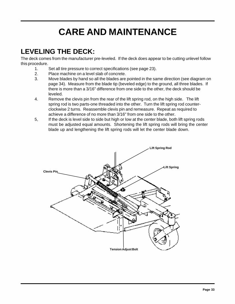
LEVELING THE DECK:The deck comes from the manufacturer pre-leveled. If the deck does appear to be cutting unlevel followthis procedure.
1. Set all tire pressure to correct specifications (see page 23).2. Place machine on a level slab of concrete.3. Move blades by hand so all the blades are pointed in the same direction (see diagram on
page 34). Measure from the blade tip (beveled edge) to the ground, all three blades. Ifthere is more than a 3/16" difference from one side to the other, the deck should beleveled.
4. Remove the clevis pin from the rear of the lift spring rod, on the high side. The liftspring rod is two parts-one threaded into the other. Turn the lift spring rod counter-clockwise 2 turns. Reassemble clevis pin and remeasure. Repeat as required toachieve a difference of no more than 3/16" from one side to the other.
5, If the deck is level side to side but high or low at the center blade, both lift spring rodsmust be adjusted equal amounts. Shortening the lift spring rods will bring the centerblade up and lengthening the lift spring rods will let the center blade down.
CARE AND MAINTENANCE
Clevis Pin
Lift Spring Rod
Lift Spring
Tension Adjust Bolt

Page 34
DECK SPINDLE BELT DIAGRAM(Top View))
CARE AND MAINTENANCE
BLADE TIP
DISCHARGE SIDE

Page 35
STANDARD SERVICE PARTS LISTMODEL ZTR 6025:
BLADES: Hi-Lift: P/N 60295Lo-Lift (standard): P/N 60293
BELTS: Serpentine Belt: P/N 60194 (48")P/N 60186 (60")
Engine To Hydros: P/N 61101Clutch to Driveshaft: P/N 60187
Hydrostatic Transmission Filter: P/N 7252
KOHLER AIR AND OIL FILTER PART NUMBERS:
Refer to engine manufacturers manual for recommendations regarding frequency of servicerequired for engine oil changes and air filter maintenance.
Protect your engine investment, use only original equipment filters.
Model ZTR 6025: 25HP Air Filter & Pre-Cleaner 78003Engine Oil Filter 78006
IMPORTANT:
Some applications, extreme dirt conditions, or the use of a grass catcher mayrequire that the engine used on the Model ZTR 6025 be fitted with an OPTIONALKohler fresh air filter system.
Listed below are the Kohler kit numbers required to adapt these components to theengine. Consult your dealer or a Kohler engine service center for additionalinformation.
Model ZTR 6025: 25HP Check with Kohler Dealer for availability

Page 36
1. ENGINE WON'T TURN OVERMower blades engagedDrive not in neutralBlown fuseDead batterySolenoidIgnition switchStarter
2. ENGINE WILL TURN OVER BUT WON'T STARTNo gasOver or under chokedSpark plug not firingCarburetor maladjustmentIgnition Switch
3. HARD TO START ENGINEFuel line cloggedFaulty fuel pumpSpark plug wire loose or groundedSpark plug(s) faulty or improperly gappedElectronic ignition defectiveDirty or maladjusted carburetor
4. ENGINE STARTS BUT CUTS OUTWater in gasolineClogged fuel lineVent in fuel cap pluggedFaulty fuel pumpMaladjusted carburetorEngine dies when control levers are moved "IN"
5. ENGINE KNOCKSLow oil levelIgnition timing offFuel octane too lowOver heated engine
TROUBLESHOOTING
--------------------------------------------------------------------------------------------------------disengage blades----------------------------------------------------------------move steering control levers to neutral "OUT " position
-------------------------------------------------------------------------------------------------------------------------------replace fuse---------------------------------------------------------------------------------------------------------------------charge or replace
-------------------------------------------------------------------------------------------------------------------------------consult dealer-------------------------------------------------------------------------------------------------------------------------consult dealer
----------------------------------------------------------------------------------------------------------------------------------consult dealer
-------------------------------------------------------------------------------------------------refuel and/or clean or replace fuel filters----------------------------------------------------------------------------------------------------------------adjust choke
---------------------------------------------------------------------------------check spark plug/condition or reset gap---------------------------------------------------------------------reset carburetor adjustment/consult dealer
--------------------------------------------------------------------------------------------consult dealer for carburetor service
--------------------------------------------------------------------------------------------clean fuel line and check fuel filter---------------------------------------------------------------------------------------------------------------------consult dealer
-----------------------------------------------------------------------------------check spark plug wires--------------------------------------------------check spark plug/condition and reset gap*
---------------------------------------------------------------------------------------------------------consult dealer------------------------------------------readjust carburetor* or consult dealer for carburetor service
-----------------------------------------drain old gasoline-replace with new gasoline and/or clean carburetor bowl-------------------------------------------------------------------------------clean carburetor bowl and or check fuel filter
----------------------------------------------------------------------------------------------------------------check vent---------------------------------------------------------------------------------------------------------------------consult dealer
------------------------------------------------------------------------------------------------------readjust carburetor------------------------------------------------------parking brake set -- release brake
----------------------------------------------------------------------------------------------------------------------check and add oil---------------------------------------------------------------------------------------------------------------------consult dealer
---------------------------------------------------------------------------drain and replace with higher octane gasoline--------------------------------------------------------------------------------------------shut off engine and allow to cool
*See engine manual for engine adjustments

Page 37
TROUBLESHOOTING
----------------------------------------------------------------------------------------------------------------Consult dealer--------------------------------------------------------------------------------------------------------Readjust carburetor
-------------------------------------------------------------------------------Check spark plug or condition and reset gap*---------------------------------------------------------------------------------------Slow down on rough terrain
-----------------------------------------------------------------------------------Clean Intake screen and fins------------------------------------------------------------------------------------------------------------------Consult dealer
-----------------------------------------------------------------------------------------------------------Adjust oil level---------------------------------------------------------------------------------------------------------------Consult dealer----------------------------------------------------------------------------------------------------------Run engine faster
(NOTE: Always mow at full throttle setting.)
-----------------------------------------------------------------------------------------------------------Consult dealer--------------------------------------------------------------------------------------------------Check and re-gap plug*
----------------------------------------------------------------------------------------------------------Consult dealer*
------------------------------------------------------------------------------------------------Re-tension or replace-----------------------------------------------------------------------------------------------------------------Reconnect
---------------------------------------------------------------------------------------------------Reconnect----------------------------------------------------------------------------------------------------------------------------Add oil
---------------------------------------------------------------------Put in lock position (see pg.19)--------------------------------------------------------------------------------------------------------------Replace filter
-----------------------------------------------------------------------------------------------------------------------Consult dealer-------------------------------------------------------------------------------Consult dealer
----------------------------------------------------------------------------------------------------------------------------Bleed air--------------------------------------------------------------------------------------------------------------Check
-----------------------------------------------------------------Add Oil or drain oil as needed -----------------------------------------------------------------------------------------------------------------Consult dealer
-----------------------------------------------------------------------------Overfilled or water contaminated
------------------------------------------------------------------------------------------------------------------------Sit on seat----------------------------------------------------------------------------------------------------------------Consult dealer
-----------------------------------------------------------------------------------------------------------Consult dealer---------------------------------------------------------------------------------------------------------Reroute---------------------------------------------------------------------------------------------Clean under deck
*See engine manuals for engine adjustments
6. ENGINE SOMETIMES SKIPS AT HIGHER SPEEDIncorrect ignition timingCarburetor maladjustedFaulty spark plugsBouncing off seat safety switch
7. ENGINE OVERHEATEDAir intake screen or fins cloggedFuel mixture too leanOil level too low or too highImproper ignition timingRunning engine too slow
8. ENGINE IDLES POORLYCarburetor maladjustmentImproper spark plug gap
9. ENGINE BACKFIRESCarburetor maladjustment
10. ENGINE RUNS BUT MOWER WON'T MOVE FORWARDDrive belt broken or slippingShift linkage disconnectedTransmission shift arm disconnectedTransmission oil lowTransmission locks in free wheel positionHydrostat oil filter pluggedBad transmissionGear mating transmission/gearbox disconnectedAir in transmissionNot enough tension on drive belt
11. MOWER LOSES POWER/ TRANSMISSION OVERHEATSHydrostat transmission oil too low or too highTransmission damageTransmission blowing oil out cap
12. ENGINE STALLS WHEN BLADES ARE ENGAGEDOperator not on seatFaulty interlock systemBad blade spindle bearingDeck drive belt not properly routedBlades blocked by foreign material

Page 38
NOTES

Page 39
DATE PURCHASED
MOWER MODEL NUMBER
MOWER SERIAL NUMBER
PURCHASED FROM
OWNERINFORMATION
DATE OIL CHANGED: DATE ENGINE TUNED:
Address
Name
DIXON INDUSTRIES, INC.A BLOUNT International Inc. Co.PO BOX 1569COFFEYVILLE KS 67337 0945316 251 2000FAX 316 251 4117

Page 40
Dixon® and ZTR® are registered trademarks of Dixon Industries, Inc.
The Engine Exhaust from this product contains chemicals known to the State ofCalifornia to cause cancer, birth defects or other reproductive harm.WARNING:
DIXON INDUSTRIES, INC.A BLOUNT International Inc. Co.PO BOX 1569COFFEYVILLE KS 67337 0945316 251 2000
6000 Series6025Part No. 13090-0700