Embed Size (px)
Citation preview

BASCOM-TURNER
INSTRUMENTS
GAS-EXPLORER DETECTORS
OPERATION MANUAL
NATURAL GAS, CARBON MONOXIDE, OXYGEN
Part Number OM-0101

LIMITED WARRANTY
Bascom-Turner Instruments warrants Gas-Explorer Detectors to be free from defects
in materials and workmanship for one year following the date of shipment. This
limited warranty applies to the original purchaser of the Detector and is not
transferable except by Bascom-Turner's authorized Distributors.
The instruments described in this manual are produced with standard commercial
parts, any of which may fail under some circumstances. Although the probability of
such failure is low, it is not zero. Accordingly, all personnel using such instruments
must be trained to recognize instrument malfunctions and to have such instruments
repaired promptly. Bascom-Turner offers no warranty that failures will not occur –
only that when they occur, they will be promptly cured with the following procedure:
During the limited warranty period, we will repair or replace, at our option, any
defective products or parts at no additional charge. A return merchandise
authorization (RMA) number must be obtained prior to returning a detector to
Bascom-Turner. A detector returned to Bascom-Turner with probe and water-block
filter, shipping prepaid, will be repaired, calibrated and returned second day air.
Warranty repairs do not include pump cleaning, filter replacement and calibration.
All replaced parts and products become the property of Bascom-Turner Instruments.
This limited warranty does NOT extend to any Detectors which have been damaged as
a result of accident, abuse, modification, misuse, such as failure to follow the operating
instructions provided by Bascom-Turner Instruments, or other contingencies beyond
our control. No other warranty is expressed or implied. Bascom-Turner is not liable
for consequential damages.
CAUTION
Personnel who operate, calibrate, or repair this instrument must
first read and fully understand this manual in its entirety.
For use in Class I, Division 1, Group D atmospheres.
These products have not been tested for intrinsic safety in oxygen
enriched atmospheres.
Change batteries, service, and use the USB interface only in
areas known to have non-hazardous atmospheres.
TABLE OF CONTENTS
FEATURES
SPECIFICATIONS
PART 1. OPERATION
1. The Gas-Explorer Detectors....................................................................................…… 1
2. Essential Operating Practice ...................................................................................…… 2
3. Operational Description ..........................................................................................…… 3
4. Instrument Checks...................................................................................................…… 6
5. Interference from Other Gases, Liquids or RFI ......................................................…… 7
6. Change of Batteries .................................................................................................…… 8
7. Probes ......................................................................................................................…… 9
8. Routine Maintenance ..............................................................................................…… 10
PART 2. SETUP, CALIBRATION AND ALARM LEVEL SELECTION
1. Setup………... ………………………………………………………………………… 12
2. Further Setup Parameters ........................................................................................…… 12
3. Calibration………...…………………………………………………………………… 13
PART 3. THE USB INTERFACE
1. Downloads……………. ……………………………………………………………….. ...…………………………………………………………………….
14
2. Reports……...………………………...………………………………………………... 16
3. Maintenance …………………...………………………………………………………. 18
PART 4. MAINTENANCE
1. Sensor and Pump Installation ..................................................................................…… 20
ACCESSORIES AND SPARE PARTS
i


FEATURES
The Gas-Explorer portable methane, and combined methane, carbon monoxide, and oxygen detectors are intrinsically safe, microprocessor based instruments designed to test ambient air and flue gas over a wide temperature range.
These detectors have many features for easy and reliable operation:
• Measurements Over the Full Range of Gas The instruments detect methane over the full range of methane concentrations up to 100% GAS. Peak and current readings are displayed simultaneously.
• Track Gas A sensitive, calibrated scale with 20ppm resolution and quick response makes it easy
to find gas leaks.
• Bar Holing
Peak and sustained bar-hole readings are automatically displayed after gas is pumped for a precise, fixed time.
• Automatic Data Storage and Reports
Automatic storage of time and mode-stamped readings. Automatic storage of the last 24 calibrations. Automatic generation of reports.
• Automatic Calibration Calibration is performed automatically using Bascom-Turner's calibration gas.
• Automatic Sampling An intrinsically safe automatically samples ambient air, flue gas, or bar hole gas.
• Automatic Self-Tests Automatic checks of battery, sensors, and pump. Tests for blockage and for tight connection of probe to instrument.
• Audible and Visual Alarms Audible and visual alarms individually set. Continuous monitoring of natural gas, and (optionally) CO and O2.
• Easy-to-Use
Simple operation without complicated or confusing displays. A short operating manual is stored onboard.
• Easy-to-Read, Back-Lit, Bright Display A bright, large LCD display is easy to read both indoors and outdoors.
• A Water-block Filter
A special Teflon filter keeps water out.
• A Tough Package and a Light Weight Housed in a high impact, ploycarbonate-nylon alloy case, the instrument weighs only 24 ounces.
iii


SPECIFICATIONS
Gases Detected Natural Gas (Methane) Carbon Monoxide (CO) [Optional]
Oxygen (O2) [Optional]
Sensors Dual Catalytic Combustion (CH4) Thermal Conductivity (CH4) Electrochemical (CO, O2)
Ranges
GAS 0 to 40,000 ppm CH4 by volume 0 to 100% CH4 by volume
PPM CO 0 to 2000 ppm carbon monoxide
% O2 0 to 40% by volume
ii
Data Storage 24 calibrations
And 2 to 3 months readings (typical)
Reports Exposure and Bar-Hole Measurements, Calibration History, Sensor Sensitivity, Operational Periods by User and Unit ID, Office Reports
Accuracy CH4:
2% of reading ± 20ppm
(10°C to 30°C) ±0.1% to 5%; ±2.0% to 100 vol %
CO: ±5% of reading ±10 ppm
O2: ±0.2% vol %
Resolution
GAS 20 ppm from 0 to 40,000 ppm
CO
0.05 vol % from 0 to 5 vol % 1.0 vol % from 5 to 100 vol % 1 ppm
O2 0.1 vol %
Warm-Up Time 60 seconds
Response Time: CH4:
CO:
O2:
0.7 seconds 45 seconds 60 seconds
Operating Temperature
-20oC to 40oC (0oF to 105oF)
Storage Temperature -40oC to 60oC (-40oF to 140oF)
Humidity
Power Supply
0 to 95% RH Two C-size Alkaline or Two C-size Rechargeable NiMH
Continuous Operating
Time per Battery Set
10 hours typical (25oC)
Weight 24 oz. (680 g)


1
I. OPERATION
1. THE GAS-EXPLORER DETECTORS
This manual describes the operation of the family of Gas-Explorer detectors for natural gas, carbon monoxide and oxygen.
Model EGI -201 - Detects natural gas and displays it as % LEL or % GAS Model EGI -211 - Detects natural gas and displays it as % GAS Model EGC-301 - Detects natural gas and carbon monoxide and displays % LEL or
% GAS and PPM CO (parts per million of CO) Model EGC-311 - Detects natural gas and carbon monoxide and displays % GAS and
PPM CO (parts per million of CO) Model EGO-321 - Detects natural gas and oxygen and displays % LEL or % GAS and
% Oxygen. Model EGO-322 - Detects natural gas and oxygen and displays %GAS and %Oxygen. Model EGA-411 - Detects natural gas, CO, and oxygen and displays % LEL or
% GAS, PPM CO and % Oxygen. Model EGA-412 - Detects natural gas, CO, and oxygen and displays % GAS, PPM
CO and % Oxygen.
All models display gas in ppm in the Track Gas mode.
All models may be used to test ambient air and bar hole for natural gas to locate gas leaking from pipes and other conduits. All models which detect carbon monoxide (CO) may be used to test for CO in ambient air, flue gas, and gases given off by appliances.
A detector alerts the user acoustically and visually, by "flashing" the symbol(s), for the detected gas(es) whose concentration exceeds preset limits. Visual alarms are displayed in-between readings. For example, the display will flash "CO", approximately every two seconds, in-between normal Monitor mode displays. If the concentration of natural gas also rises above its alarm limit, the display will flash “GAS”, then a normal Monitor mode display, then "CO", and so on. Simultaneously, the sound alarm will be on.
Visual alarm symbols are “GAS” for natural gas, "CO" for carbon monoxide. "Low
Oxygen" for low oxygen, and "High Oxygen" for high oxygen.
Factory set alarm limits are 1.0% methane, 35 ppm CO, and 19.5% for low and
23.0% for high oxygen.
No alarms are given in the Bar Hole mode.
WARNING: Each detector responds to the gases for which it was designed. Other toxic
or dangerous gases may not be detected.
2
2. ESSENTIAL OPERATING PRACTICE
Gas-Explorer detectors are easy to use. A detector is turned on by pressing the left button; its operation is controlled by three buttons whose function is shown on the display. The middle button generally toggles “Mute” on and off. Once the appropriate display is selected, operation is automatic. However, a few general rules must be followed to insure reliability.
Pump. Gas-Explorer detectors have a built-in pump and depend on this pump for their operation. If the pump is not functioning normally, the instrument will not function properly. It is therefore essential to check the pump each time the instrument is turned on.
Pump Test: Connect the probe you plan to use and turn the instrument on. After the display shows “Block Intake”, block the probe tip with your finger to show "Pump OK".
If "Pump OK" does not appear, tighten all connections and repeat the test. If a block condition is still not observed, remove the probe and block directly the inlet to the instrument. If "Pump OK" still does not appear, return the instrument for repair.
Filters. Dust and water-block filters protect the sensors and the pump from dust and accidental intake of liquid water. Just as a car would not be operated without air and fuel filters, do not operate a detector without a filter on the probe. Operation without this filter will eventually degrade the pump. It also voids the limited warranty.
It is essential that the filter be replaced monthly or sooner if it turns brown. Operation without a filter will degrade the natural gas sensor and will void the warranty. Filters are available from Bascom-Turner in packages of five, Part No. WF-505.
Zero Check. All sensors drift to some extent over time. Sensor drift is automatically corrected by zeroing if the drift is within 0.1% vol. GAS (and 10ppm CO if the unit is equipped with a CO sensor). If the drift is outside this limit, “NO GO” is displayed and the user is asked to “restart the unit in clean outdoor air.” The user can override these limits and re-zero the instrument unless the zero has drifted over 0.5% vol. GAS, in which case the instrument should be checked by a trained professional (the sensor may need replacement). It is important that the zero adjustment be done in clean air, for example, outdoors. If the sampled gas is not clean, a systematic error may be introduced in subsequent measurements.
WARNING: On a call, turn the instrument on outdoors, not indoors.
Test and Calibration. Gas-Explorer detectors must be checked and calibrated periodically with gas of known composition. The catalytic combustion and carbon monoxide sensors depend on catalysts which may loose activity or get poisoned during use. When this happens, there will be diminished response.
The necessary frequency of calibration depends on actual use and on the concentration of catalyst poisons in the sampled gas. This concentration is, or course, not generally known.
A detector can be tested with "bump" gas. Such tests verify that the gas sensor(s) are in operating condition. To verify and adjust, if necessary, their sensitivity they must be calibrated.
A detector can be automatically calibrated in approximately one minute using Bascom-Turner's calibration gas (2.5% CH4 and 100 ppm CO in air). Given the ease and speed of automatic calibration, it pays to calibrate as frequently as possible, and certainly, no less than monthly.

3
3. OPERATIONAL DESCRIPTION
To conserve the batteries, the instrument should be turned OFF when not in use.
The instrument is controlled by three push button switches whose function changes with each particular display. A label for each key is shown on the display.
To turn the instrument on, press the left switch. A series of screens is automatically displayed preparatory to entering the first operational mode, viz. “Monitor” (see Section below). Along the way, a number of specialized screens can be used to access specialized functions.
The first screen shows the Model Number and the second displays the gases detected by the particular instrument and provides access to the USB interface (see Part 3). The next screen shows the date and time and a measure of the state-of-charge of the batteries. To edit the date or time, press the right “Edit” button. The first digit of the display will begin flashing and can be edited by pressing the right “Update” button. Pressing the left “Next” button advances the flashing digit to the next position which can be edited (or not) by pressing the right button, and so on. The same screen provides access to a short manual by pressing the “Help” button.
Following the Edit/Help screen, the pump is tested (“Block Pump” screen). If no block is detected in 40 seconds, “Check Probe” is displayed, followed by “Remove Probe and Block
Intake” and finally “Repair Pump” followed by an automatic turning off of power.
The next display suggests a “Calibrate by [a date thirty days from the date of the last calibration]” and an opportunity to calibrate (see Part 2, Calibration). If calibration is not chosen, the instrument proceeds to enter the operational mode of “Track Gas” (see below).
The period of thirty days between calibrations is only a suggestion. The instrument should be calibrated as often as possible, ideally every day. In any case, if poisoning of the natural gas sensor or some other problem is suspected, the instrument should be promptly checked by calibration with CAL Gas (see Part 2, Calibration).
Backlight. Pressing any button backlights the display for 20 seconds. To backlight any display, press the middle button twice (this sequence leaves the instrument in its original state – mute or not mute). The only exception to this procedure is during bar holing (middle button initiates sampling). Pressing the middle “Go” button automatically backlights the display long enough (60 seconds) to read the results.
Turning the Instrument Off. The instrument can be turned off from a number of (but not all) displays. Such places are obvious when a particular button is marked “Off.” In all such cases the screen accessed by pressing “Off” requires a second operation (“Yes”) to actually turn the instrument off. This sequence guards against accidental turning off.
When a direct “Off” button is not available, you may follow the procedures suggested below:
1. At the USB access display, press the left “USB” button and then after the new screen, the right “Off” button.
2. During warm-up of the Track Gas mode, press the left “BH” button, then “Go”, and then “Stop” (as soon as it appears) and then “Off.”
Operational Modes. The instrument operates in three distinct modes, “Monitor”, “Track Gas” and “Bar Hole”.
4
Monitor: The detector shows the concentration of natural gas (methane) in air in steps of 0.05% GAS (1% LEL) up to 5% GAS (100% LEL) and then in steps of 1% GAS up to 100% GAS. The concentrations of CO and O2 are also shown if the unit is equipped with the corresponding sensors (see below).
The peak reading for GAS is retained and displayed along with the current readings until the unit is turned off or another mode of operation (Track Gas or Bar Hole) is chosen.
Models EGI-201, EGC-301, EGO-321, and EGA-411 display concentrations in increments of 1% LEL up to 100% LEL and then in increments of 1% vol. from 5% to 100% GAS. All other models display % vol. from 0 to 100% GAS in increments of 0.05% up to 5% and then in increments of 1% to 100% GAS.
Track Gas: Connect an appropriate probe (see Section 7) and select "TRACK GAS". The display shows "TRACK GAS" for a few seconds. After warm-up, the display shows the concentration of gas in air in parts per million by volume (ppm). Advance a probe along the pipe or other conduit suspected of having a gas leak. The beeper will sound if the ambient concentrations of gas rises above 20ppm. Since methane is lighter than air, track a conduit from above whenever possible. Sometimes it is desirable to silence the beeper during a leak survey. To silence the beeper, press the middle switch. “Mute” will appear on the display and the beeper will be silent. If the gas concentration goes over 40,000 ppm, (4% Gas) the unit automatically returns to the Monitor Mode.
Bar Holing: The detector may be used to measure gas levels in sampling holes used for locating underground natural gas resulting from seepage or leaks in a conduit. Gas concentrations in a bar hole near a significant leak will exceed several percent. Therefore an alarm for gas is likely, but since it is not relevant to the ambient atmospheres above ground it will not sound. During bar-holing, the alarms for all gases are automatically turned OFF.
To bar hole, select an appropriate probe (see Section 7) and set the front panel to Bar Hole (BH) The instrument will automatically clear any residual gas and check for clean air. The pump is then turned off and the instrument is ready for bar holing. After inserting the probe into the bar hole, press “GO” (the middle switch). The pump is turned on and the instrument samples
gas for a fixed time (factory set time is 15 seconds). Readings during sampling are shown on the display. At the end of the fixed time, the instrument turns off the pump and displays the peak and sustained readings. Both values are in % GAS.
If in the course of bar holing, water is encountered, press the left “Stop” button to stop the pump. Use of a water-stopper (see Fig. 2 in Section 8) will prevent water from entering the instrument.
WARNING: If a check is to be made for trace amounts of gas, for example around the
foundation of a structure, the Monitor or Track Gas – not the Bar Hole –
mode is used.

5
To Detect Carbon Monoxide
Carbon Monoxide in Ambient Air
Connect an appropriate probe with a water-block filter and select the Monitor mode. After warm-up, the display shows the concentration of CO in parts per million (ppm). If the air is clean (contains no carbon monoxide), the display should read zero. If it does not, use the right button (“Zero/Off”) to get a new zero in clean air.
Carbon Monoxide in Flue Gas
Connect the flue gas probe, with an attached flue gas filter, to the water-block filter on the hose and select the Monitor mode. After warm-up, insert the probe into the flue and read the concentration of CO in parts per million. A flue gas check of CO should take one minute or less. For every minute of flue gas sampling allow the detector a minute of room air sampling to dry the filters.
CAUTION: The filter provided with the flue probe must be used to avoid interference by nitrogen oxides present in combusted gas. A filter is good for about three months of ordinary use. It should be replaced or refilled when about 90% of its purple material has changed color to brown, or when it gets clogged or flooded (see "Accessories and Spare Parts", Flue Gas Filter, Part No. FF-005 and Purple Beads and Spare Retaining Disks, Part No. PR-050).
Note: The standard flue gas probe and filter are suitable for spot checks lasting a minute or two. For measurements of CO in flue gas over longer periods use an Extended Duty Flue Gas Probe and Filter (Part No. FP-012).
WARNING: Do not touch the flue probe immediately after a measurement. Wait
until it cools. Running the instrument in air helps cool the probe.
"Air-Free" CO Flue Measurements
The EGA-411/412 detectors can display measurements of CO on an "air-free" basis if this feature is selected (see Part 2). When this selection is made, the measured CO concentration is referred to air-free flue gas according to:
"Air-Free" PPM CO = 20.9
20.9 measured % O2(measured ppm CO)
−
The instrument displays CO concentrations on an air-free basis using the above relation. The CO reading on the display is labeled by ppm AFCO, i.e. air-free CO. This calculation is used up to 16.0% Oxygen. Beyond this, measured CO concentrations are displayed without
conversion, i.e., the "air-free" formula is not used.

6
4. INSTRUMENT CHECKS
Automatic Sensor Check
If a gas sensor fails (opens up), the display shows “Replace Methane Sensor”.
Automatic Pump Check
If the intake is blocked, the display shows "Flow Blocked" and the detector beeps until the problem is cleared. During the power on sequence, if a blocked flow is not detected within 40 seconds (from manually blocking the intake to the pump), the detector displays “No Block
Check Probe” then “Remove Probe and Block Intake”, and finally “Repair Pump”.
Check for Tight Connections
To check for tight connections, block the probe inlet to observe "Flow Blocked" on the display. If "Flow Blocked" fails to appear, there may be a leak.
WARNING: The instrument will not operate when first turned on if it fails to block when the
air intake is blocked. Subsequently, however, connections can only be checked by
blocking the probe inlet and observing “Flow Blocked” on the display. If “Flow
Blocked” fails to appear, the probe and/or inlet must be checked for leaks.
Automatic Zero The zero is adjusted automatically whenever “zero” is chosen in a display.
CAUTION: Zero adjustment must be carried out in clean air to avoid systematic errors.
Accuracy. A properly operating and calibrated detector will respond with the specified accuracy. If combustible gases other than the gas used for calibration are likely or suspected, the
instrument cannot be relied upon to give a proper indication of their concentration and hence of how close to their combustible limits they may be. For example, the detector responds quite differently to gasoline, to methane, and to propane. Accordingly, readings of % LEL (or its equivalent in percent gas) refer only to the calibration gas and can be relied upon only in this respect in assessing an atmosphere sampled by the detector.
Safety. These instruments measure the concentration of natural gas in air and give, more generally, an indication of the presence of other combustible gases. When used by trained personnel, they constitute one element for assessing the safety, or lack thereof, of a particular
atmosphere. However, they must not be relied upon by themselves for judging safety; all
other significant factors must be taken into account. A trained technician should consider possible interferences, physical or chemical, and be aware that calibrated values are only valid in air. Finally, although there are built-in safeguards, a specific instrument may malfunction. It is therefore imperative that other indicators, including, for example, odorant levels, must be taken into account.
WARNING: Catalytic combustion sensors do not respond in inert or reducing
atmospheres. Also, they should not be used for detecting combustible
dusts.

7
5. INTERFERENCE FROM OTHER GASES, LIQUIDS, OR RFI
The methane detectors use two sensors:
i) A catalytic combustion filament calibrated with methane. It is used up to about the lower flammable limit (5.0% by volume) of methane.
ii) A thermal conductivity sensor calibrated with methane. It is used from the lower flammable limit (5.0 vol %) to 100 vol % of methane.
Models EGC-301 and EGC-311 use the sensors listed above and:
iii) A three-electrode, electrochemical cell for carbon monoxide.
Models EGO-321 and EGO-322 (methane and oxygen detectors) use the methane sensors listed above and:
iv) A two-electrode, electrochemical cell for oxygen.
Models EGA-411 and EGA 412 use all four sensors.
Gases, or liquids with appreciable vapor pressure, which may interfere with the detection of methane include substances which combust on the catalytic combustion filament (examples are ethane, propane, ethylene, propylene, octane, and the like) and substances which differ in thermal conductivity from air (examples are hydrogen, helium, carbon dioxide, other hydrocarbons).
Gases or vapors which may interfere with carbon monoxide detection include substances which can be electrochemically oxidized or reduced on the working electrode of the electrochemical sensor. Examples are hydrogen, hydrogen sulfide, oxides of nitrogen, alcohols, and unsaturated hydrocarbons.
Many of the substances that interfere with CO are removed by the flue gas filter (Part No. FF-005). This filter can be used for both flue gas measurements and for ambient air measurements of CO whenever the ambient concentration of other oxidizable substances is significant.
Radio Frequency Interference
The Gas-Explorer detectors have an interior coating on their cases to suppress radio frequency interference (RFI).
WARNING: The methane and CO sensors use catalysts which may be poisoned by air
contaminants. These sensors should not be exposed to atmospheres that contain
silicones, halogens and halides, such as chlorides, and volatile compounds
containing lead or antimony. If exposure to atmospheres that adversely affect the
sensors is suspected, the detector should be recalibrated promptly.

8
6. CHANGE OF BATTERIES
Gas-Explorer detectors may be powered by two (2) alkaline (non-rechargeable) C-size batteries (1.5V, Type AM-3) or by two rechargeable batteries sold by Bascom-Turner. The batteries are good for at least eight, and typically twelve, hours of continuous operation. When the batteries are drained to about one hour of remaining continuous use, the unit alarms and the display flashes "Low Batteries" between readings. If battery life is over, the unit displays "Low
Batteries" and powers down, and the batteries must be changed to make the instrument operational.
WARNING: The batteries must be changed in an atmosphere known to be non-
hazardous.
To change batteries: 1. Turn instrument OFF.
2. Remove spent batteries.
a) Unscrew the battery cap and slide out two C-cells. b) Discard two alkaline C-cells.
3. Insert two, fresh C-size alkaline batteries.
4. Replace the battery cap and give it one quarter turn (battery cap bar vertical). Note that the batteries are inserted with the positive terminal first.
If the instrument does not operate after battery replacement, there is a high probability
that a battery has been inserted with the wrong polarity. Re-insert the batteries taking extra care to insert each battery correctly.
Note: Always replace a set of batteries with a new set. When operating in cold weather (below -10oC) use a fresh set of batteries, if possible.
WARNING: Do not attempt to charge the alkaline (non-rechargeable) batteries because
they may leak or vent.
WARNING: Use only alkaline batteries or rechargeable batteries sold by Bascom-
Turner in a Gas-Explorer.
WARNING: To reduce the risk of a battery venting, do not mix old batteries with new
batteries, or mix batteries from different manufacturers.
WARNING: Do not attempt to service the instrument in a hazardous atmosphere.

9
7. PROBES
Metal Gooseneck Probe The metal gooseneck probe (Part No. GP-514) is a 14 inch long flexible probe which
connects to the dust and water-block filter and has a quick connect fitting.
Standard Probe
The standard probe (Part No. SP-306), a rigid tube, connects to the dust and water-block filter. If extra length is desired, an extension (7", SP-308) is screwed finger-tight onto the end of the probe. A rubber gas collector (Part No. RT-107) is useful for finding leaks under windy conditions.
CAUTION: Do not use this probe for flue gas measurements. The plastic probe may become soft, deform, or decompose.
Flue Gas Probe
The flue gas probe (Part No. FP-110) is a telescoping metal probe screwed finger-tight into the flue gas filter. The other end of the filter attaches to the dust and water-block filter. This probe, together with its filter, may also be used for CO measurements in ambient air.
CAUTION: Never attach the flue gas filter cartridge directly to the sample hose - always use a dust and water-block filter.
WARNING: Hold the probe without touching the metal while it is in the flue and
immediately afterwards. Running the instrument in air after a
measurement will help cool the probe quickly and dry the filters.
Bar Hole Probes
There are four optional probes suitable for bar holing:
Bar Hole/Ceiling Probe (Part No. BP-034) 34" long, clear, one hole at end. Bar Hole Probe (Part No. BP-134) 34" long, clear, side holes. Bar Hole Probe (Part No. BP-436) 36" long, fiberglass, side holes Bar Hole Probe (Part No. BP-536) 36" long, steel, side holes. The bar hole/ceiling probe has a single inlet on the end and comes with a rubber gas
collector (Part No. RT-030) useful for finding leaks in overhead pipes. The stainless steel probe has an electrically insulated handle. Bar hole probes are designed to be attached to the water block filter on the hose. A convenient way to release water from a bar hole probe is with a water-stopper (Part No. WS-001) described in Section 8.
WARNING: Hold the steel bar hole probe only by the insulated handle to avoid
electrical shock from buried power lines.

10
8. ROUTINE MAINTENANCE
Dust and Water-block Filter A filter, housed in a knurled nut, removes particles of dust and dirt and blocks water.
Do not insert objects into the water block filter as they may puncture the filter. The filter needs to be replaced monthly or sooner if it turns brown. Replacement dust and water-block filters are available as Part No. WF-505 (package of 5 filters).
Figure 1. TheWF-505
CAUTION: Do not use a Gas-Explorer without a three-way or dust and water-block filter. Do not use a three-way or dust and water-block filter with a puncture.
Inlet Dust Filter
Removal of the intake connector (used to attach the sampling hose) of the detector exposes a metal filter pressfit onto the intake. These filters are not a substitute for dust and water-block filters as they will not block water or remove very fine dust and dirt. If this filter gets blocked, it may be cleaned with compressed air or replaced.
Water-stopper
The water-stopper (Figure 2) provides a quick way to continue bar holing if water is encountered in a bar-hole. The water-stopper is inserted between the dust and water-block filter and the bar hole probe. A float inside the water-stopper is connected to a plunger which blocks flow whenever the float is lifted by water. Water is released and the plunger returned to its normal position by depressing a release push-button.
Figure 2. Water-stopper

11
Dust-Stopper
The dust-stopper is a filter with a large surface area on which dust can collect without slowing the sampling rate of the Gas-Explorer. The filter element is easily cleaned or replaced by removing the threaded cap and either blowing off the filter element or pulling it off and replacing. Replacement dust filter cartridges are available as Part No. DF-105. The dust-stopper should be used between the dust and water-block filter and the probe or water-stopper.
Flue Gas Filter
This filter is designed to be screwed finger-tight between the telescoping metal probe and the dust and water-block filter. It must be used for CO measurements in flue gas and may also be used for CO measurements in ambient air. The beads in the filter cartridge should be replaced when about 90% of the material has changed color from purple to brown or when it becomes blocked by soot or water. Filter beads for refilling approximately 50 cartridges are available as Part No. PR-050. Replacement flue gas filters are available as Part No. FF-005 (package of 5 filters).
To refill the filter cartridge, remove threaded top and pour out spent filter material.
Retrieve the plastic retainer disk from the spent filter material. Fill cartridge with fresh filter material to bottom of threads and place the plastic retainer disk flat on top of the filter material. Screw in top until finger tight and check seal with block tests.
CAUTION: Do not remove or puncture the white filter in the bottom of the filter cartridge. If this filter becomes damaged, discard the filter cartridge.
Heavy Hydrocarbon Filter
A heavy hydrocarbon filter, filled with activated carbon, is designed to be used with the standard probe or the bar hole probe on a one-time-only basis. Activated carbon adsorbs gasoline and other heavy hydrocarbons (for example, propane or butane) which interfere with methane detection. In order to keep the filter material from adsorbing hydrocarbons prior to use, the filter is fitted with plastic endcaps which must be removed just before use. The filter should be either discarded after use or refilled with activated carbon and recapped with the plastic endcaps. This filter is designed to be screwed finger-tight between the probe and the dust and water-block filter. Activated carbon for refilling approximately 50 cartridges is available as Part No. HR-050. The refill procedure is the same as described for the flue gas filter. Heavy hydrocarbon filters are available as Part No. HF-005 (package of 5 filters).
The heavy hydrocarbon filter can also remove some alcohols and unsaturated
hydrocarbons which can interfere with CO readings. The filter should be discarded or refilled after each use.
12
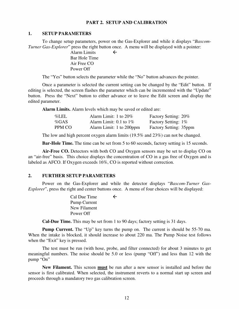
PART 2. SETUP AND CALIBRATION
1. SETUP PARAMETERS
To change setup parameters, power on the Gas-Explorer and while it displays “Bascom-
Turner Gas-Explorer” press the right button once. A menu will be displayed with a pointer: Alarm Limits �
Bar Hole Time Air Free CO Power Off
The “Yes” button selects the parameter while the “No” button advances the pointer.
Once a parameter is selected the current setting can be changed by the “Edit” button. If editing is selected, the screen flashes the parameter which can be incremented with the “Update” button. Press the “Next” button to either advance or to leave the Edit screen and display the edited parameter.
Alarm Limits. Alarm levels which may be saved or edited are:
%LEL Alarm Limit: 1 to 20% Factory Setting: 20% %GAS Alarm Limit: 0.1 to 1% Factory Setting: 1% PPM CO Alarm Limit: 1 to 200ppm Factory Setting: 35ppm
The low and high percent oxygen alarm limits (19.5% and 23%) can not be changed.
Bar-Hole Time. The time can be set from 5 to 60 seconds, factory setting is 15 seconds.
Air-Free CO. Detectors with both CO and Oxygen sensors may be set to display CO on an “air-free” basis. This choice displays the concentration of CO in a gas free of Oxygen and is labeled as AFCO. If Oxygen exceeds 16%, CO is reported without correction.
2. FURTHER SETUP PARAMETERS
Power on the Gas-Explorer and while the detector displays “Bascom-Turner Gas-
Explorer”, press the right and center buttons once. A menu of four choices will be displayed:
Cal Due Time � Pump Current New Filament Power Off
Cal-Due Time. This may be set from 1 to 90 days; factory setting is 31 days.
Pump Current. The “Up” key turns the pump on. The current is should be 55-70 ma. When the intake is blocked, it should increase to about 220 ma. The Pump Noise test follows when the “Exit” key is pressed.
The test must be run (with hose, probe, and filter connected) for about 3 minutes to get meaningful numbers. The noise should be 5.0 or less (pump “Off”) and less than 12 with the pump “On”
New Filament. This screen must be run after a new sensor is installed and before the sensor is first calibrated. When selected, the instrument reverts to a normal start up screen and proceeds through a mandatory two gas calibration screen.

13
3. CALIBRATION
Calibration must be carried out on a new sensor the next time the instrument is turned on; with an already installed sensor, the calibration should be carried out at specified intervals. The A-CAL firmware calibrates the Gas-Explorer using calibration gas available from Bascom-Turner. The CAL gas required for automatic calibration is Bascom-Turner’s methane and CO calibration gas containing 2.5 + 0.05% methane and 100 ppm + 2 ppm CO in air. Calibration gas is provided in a disposable tank containing either 105 liters of gas (Part No. MC-105) or 620 liters (part No. MC-620). The thermal conductivity sensor can be calibrated with pure methane or natural gas. The oxygen sensor is calibrated with ambient air during power-up.
The calibration gas must be delivered at or near atmospheric pressure to ensure accurate calibration. For the 105 liter gas tanks Bascom-Turner recommends using a constant flow regulator (Part No. FR-001) set to the sampling rate of the Gas-Explorer. For the 620 liter gas tanks Bascom-Turner recommends using an on-demand regulator (Part No. FR-401), which automatically adjusts its flow to the pumping rate of the Gas-Explorer.
A-CAL Operation. For complete calibration, calibrate the thermal conductivity sensor with methane or natural gas first, and then calibrate the CO and catalytic combustion sensors with 2.5% methane and 100 ppm CO in air. For a partial calibration, calibrate the CO and catalytic combustion sensors with 2.5% methane and 100 ppm CO in air.
A-CAL Calibration with Pure Methane or System Gas. Power on the Gas-Explorer with the left “Power-On” button and while the unit displays “Calibrate By …..” press the right “CAL” button. After a successful autozero, choose the “A-CAL” button, connect pure methane or natural gas and press the left “Yes” button. The screen displays “Calibrating” for about a minute and then changes to “Calibration OK” with a display of readings taken while sampling calibration gas or “Does Not Calibrate” if calibration was unsuccessful. Three tries are allowed before the screen displays “Please Service” for 15 seconds and then the instrument turns OFF.
Calibration with 2.5% Methane and 100 ppm CO. Power on the Gas-Explorer with the left “Power-On” button and while the unit displays “Calibrate By …..” press the right “CAL” button once. After a successful autozero, choose A-CAL. With the unit’s screen displaying “Connect Calibration Gas”, connect the 2.5% methane and 100 ppm CO in air calibration gas and press the left “Yes” button. The screen displays “Calibrating” for about a minute and then changes to “Calibration OK” with a display of % GAS (and ppm CO readings if it has a CO sensor) or “Does Not Calibrate”, if calibration was unsuccessful. Pressing the left “Re-Try” button returns to the Calibration screen. If three tries at calibration are unsuccessful, the screen displays “Please Service” for 15 seconds and then the instrument turns OFF.
Following calibration, the left button leads again to calibration, the right button exits to the Monitor mode. In both cases, an intermediate screen displays the sensitivity in µw/ppm and mw/1%. The first quantity (µw/ppm) refers to the Track Gas mode, the second (mw/1%) to the Monitor mode. If the sensitivity falls below 0.5 µw/ppm, or below 8 mw/1% GAS, the gas sensor should be changed. In both cases the display reads “Please Change Methane Sensor” and the instrument is Turned Off.
CAUTION: Automatic calibration presupposes and depends on using Bascom-Turner’s calibration gas (Part No. MC-105 or MC-620). Do not use a gas of a different composition for automatic calibration.

14
PART 3. THE USB INTERFACE
The USB interface is used for docking calibration and for connecting a Gas-Explorer to a
computer for data transfer and for setting operating parameters. The cable required for the connection is a six foot long, 4-pin, mini BM plug to standard AM plug and is available from Bascom-Turner (Part No. UC-001).
Docking calibration is described in a separate manual and by prompts on the dock. Data transfer is described below.
DATA-LINK™. DATA-LINK™ is a software package available from Bascom-Turner (Part No. DL-001) for downloading and archiving data, viewing and optionally printing reports of data logged by Gas-Explorers, and for maintaining the detectors by uploading setup parameters. DATA-LINK™ can be installed on PC’s with Windows 2000 or XP Pro operating systems and equipped with a USB port.
Figure 3. Main Menu, the initial DATA-LINK™ screen
1. DOWNLOADS
The main menu allows selection of four different downloads from the detector to the PC: readings, calibrations, locations (if available), and user, unit and setup data. Also three types of reports can be selected: Readings and Exposure (TWA and STEL), Calibration, and User, Unit and Office. Four types of maintenance can be performed: resetting date and time, adding, editing and deleting locations, users, units, offices and pins, and uploading unit setup parameters. There is an on-line help menu accessible by clicking on “Help” in the upper left corner of the window. Archived data can be backed-up and restored from back-up with the two buttons below the copyright notice.

15
Readings. Readings are time and date-stamped gas concentration measurements (e.g. %LEL, %GAS, %Oxygen, and ppm CO) recorded by the detector along with identifying information such as the detector’s serial number, user’s name, the operational mode used to acquire the readings, and the state of the pump when the readings were taken. When the memory is filled, the oldest data is automatically overwritten by the new data.
The following gas concentration readings are recorded with a full suite of sensors:
Percent LEL 0 – 100% Percent O2 0 – 40% vol. Percent GAS 0 – 100% vol. PPM CO 0 – 2000 ppm
Note: % LEL readings are only recorded in detector models ending in 201, 301, 321 and 411. Standard: 100% LEL = 5% GAS; Optional: 100% LEL = 4% GAS.
The data also includes alarm flags set under the following conditions:
Start of any alarm condition Start of a low/high O2 alarm Start of LEL alarm Start of a high CO alarm
Readings and Alarm Summary. To save time, a Readings Summary data file can be downloaded resulting in the display of a Sorted Readings Table, which helps to identify when the unit was powered on and the operational mode changed. Using the data on alarm flags in the Readings Summary file, a Sorted Alarm Events table can be displayed to identify the time and date of alarm events without downloading the entire readings data file.
Calibration Data. Data from the last 24 calibrations are stored in the gas detector. The following data are stored for each calibration:
1. Key data that makes each calibration unique:
Unit Serial Number Date Calibrated Hour and Minute Calibrated Calibration Sequence 2. Before calibration readings on calibration gas 3. After calibration readings on calibration gas 4. Sensor sensitivities 5. Operational information:
Pump working OK (Y/N) Days since last calibration Calibration check OK (Y/N) Minutes operated since last calibration Number of times the unit was powered on since last calibration Methane sensor cleaned during calibration (Y/N)
User Data. The user data is stored in the detector as a single record and includes:
User Name Day Limit Between Calibrations Personal Identification Number (PIN)

16
PIN entry can be optionally required for calibrating a detector at a docking station. The PIN can be a number entered on a keypad or an alphanumeric entered on a keyboard.
Unit Data. The unit data is partially stored in the detector and completely stored in one or more PCs. Some unit data is required and some is optional.
Required Unit Data. Unit ID Number is an integer assigned to the unit when it is entered into the unit database for the first time. Unit Serial Number is the multi-digit hyphenated number on the case of the unit and permanently stored in the unit’s memory (i.e. XXXX-XXXXXX). Unit Model Number is the alpha-hyphen-numeric which appears on the label of the unit (i.e. VGC-301). Date Originally Invoiced is the date of Bascom-Turner Instrument’s invoice when the unit was originally shipped. It serves as the start of all warranty periods and mean times between failure periods.
Optional Unit Data. “Assigned to Office” is the name or number of the location where the detector will be stationed. User's name is the name or number of the person using the detector, or when the unit is retired and the reason why it is retired (i.e. Lost). Last assigned date and time is changed each time a new user's name is entered.
Setup Data. There is a factory installed setup file in every detector which contains operational parameters such as alarm levels for each gas detected, features enabled (Y/N), e.g. air-free CO, and settings such as Bar Hole time.
Downloading Data. Before downloading any data the operator is asked to verify that the unit is connected to the PC by USB. If the unit is not connected or becomes disconnected, the download program times-out and you must try again. Data is not erased in the unit after downloading so it can be downloaded multiple times. Only one copy of the data is archived in the PC no matter how many times it is downloaded from the unit to the PC.
Downloading Readings Data. It can take 5 minutes to download all the readings data from a unit to a PC. In order to save time a data summary can be downloaded, sorted, and only the desired readings can then be downloaded. The Readings and Alarm Events tables can be sorted by unit serial number, date, time, and the operational mode the unit was in when the readings were acquired in order to select the desired readings.
Downloading all readings in a time period bounded by two dates can also be done by first entering the date range and then selecting "Download Readings by Date Range".
2. REPORTS
Reports are selected from the "Readings and Exposure Reports" submenu. This submenu has two tables listing units by unit ID with each table providing different information about the units. The tables of stored alarms and readings which can be scrolled independently of each other by first left-clicking with the mouse to highlight a field, then scrolling with either the up and down arrow keys or the Page Up and Page Down keys. The tables can be searched jointly by unit ID, serial number, operational mode and date to limit the unit information displayed in the tables. Complete data can be redisplayed in both tables by selecting any of the four searches and pressing the enter key without entering any search criteria. After viewing reports on the computer’s screen they can be optionally printed.
Readings Reports. There are two readings history reports: one is tabular and the other is a screen consisting of concentration versus time plots. In order to view or print these reports the

17
unit ID of the detector which acquired the data must be entered along with a date and time range. Once the report is displayed there is a print button for obtaining a hardcopy.
Exposure Reports. There are two exposure history reports: one is tabular and the other is a screen consisting of two STEL and two TWA versus time plots. In order to view or print these reports, the unit ID of the detector which acquired the data must be entered along with a date and time range. Once the report is displayed there is a print button for obtaining a hardcopy.
Bar-Hole Report. The bar-hole report is viewed or printed by entering the unit ID of the detector along with a date and time range. A print button is used to obtain a hardcopy.
Calibration Reports. Calibration Reports are selected from the "Calibration Reports" submenu. This submenu has two tables listing units by unit ID with each table providing different information about the units. The tables can be scrolled independently of each other by left-clicking with the mouse highlighting a field, then scrolling with either the up and down arrow keys or the Page Up and Page Down keys. The tables can be searched jointly by unit ID, serial number, assigned office and user to limit the unit information displayed in the tables. The complete data can be redisplayed in both tables by selecting any of the four searches and pressing the enter key without entering any search criteria.
There are two types of calibration reports, one type is a summary of data acquired during calibration limited to a specific unit and the second type is a general report of all units.
Sensor Sensitivity History by Unit ID is a report of the date and time of each calibration and the sensitivity of each sensor with the last calibration data listed first. This report can be used to forecast sensor performance and replace sensors before they reach the lower sensitivity limit.
Calibration History by Unit ID is a report of the date and time of each calibration with before and after calibration readings of each sensor. Since the pump must work in order to calibrate a detector, this is checked first and is indicated in the "Pump OK" column in the report.
Last Calibration Data by Unit ID is a complete report of the last recorded calibration. The right hand column summarizes the date, time, pump, and sensor checks.
Units Overdue for Calibration is a report of all units not calibrated within their calibration period.
Average Cal. and Operational Periods first asks for "Prior Monthly Period Selection" with a default value of 1 month. If the averages over the last month are to be reported then select "OK", otherwise enter the desired number of months over which to average and then select "OK". The report lists units by unit ID number and has five averages for each unit:
Time/Use is total minutes unit was on divided by number of times it was turned on. Use/Day is total minutes unit was on divided by number of days in use. Uses/Day is number of times unit was turned on divided by number of days in use. CAL. Period is the number of days in use divided by the number of times unit was automatically calibrated (either docked or non-docked).
User, Unit, and Office Reports. User, unit and office reports are selected from the "User, Unit, and Office Reports" submenu. This submenu has two tables listing units by unit ID with each table providing different information about the units. The tables can be scrolled independently of each other by first left-clicking with the mouse highlighting a field, then scrolling with either the up and down arrow keys or the Page Up and Page Down keys. The

18
tables can be searched jointly by unit ID, serial number, assigned office and user to limit the unit information displayed in the tables. The full data can be redisplayed in both tables by selecting any of the four searches and pressing the enter key without entering any search criteria.
Active Unit Report is a listing of all detectors in the UNITLOG database indicated as non-retired. The report is entitled "Active Unit Data". Fields, which are columns in the tabular report, include:
Unit ID Invoice Date Serial No. Assigned to Office Model No. Assigned to User
Retired Unit Report is a listing of all detectors in the UNITLOG database indicated as retired. The report is entitled "Retired Unit Data". Fields which are columns in the tabular report are identical to the Active Unit Report.
Unit Assignment History by Unit ID is a list of each time when a unit's assigned user is changed. Whenever the Unit Edit button is used to change a unit’s assignment, there is a date and time stamped record created which provides an assignment audit trail of who began using the unit. The Unit Assignment History by Unit ID report summarizes this audit trail with a chronological list of users and the date and time when they were assigned the unit.
Unit Assignment History by User is a list of each time when a user is assigned a new unit. The Unit Assignment History by User report summarizes the assignment audit trail with a chronological list of units used by a user and the data and time when they were assigned the unit.
Office Report is a list of offices which have assigned units. The office name, office supervisor and their email address or FAX number are listed in the report.
3. MAINTENANCE
Uploading Location. From the main menu of DATA-LINK™ under Maintenance, click on the “Location” button. On the Maintain Location Data screen select a record with the desired location using the select buttons along the bottom of the table. Or add a record, if none exists for the location you are uploading. With just the desired record selected, click on the “Upload One Selected Location Record” button.
Uploading Username. From the main menu of DATA-LINK™ under Maintenance, click on the “User, Unit, Office & Pin” button. On the Maintain User, Unit, Office & Pin screen, select a record with the username you wish to upload using the select buttons along the bottom of the table. Or add a record, if none exists for the unit you are setting up, or edit an existing record for the unit with the username you would like to upload. With just the desired record selected, click on the “Upload One Selected User Record” button.

19
Readings and Exposure Report
Bar Holing reports showing peak and sustained readings

20
PART 4. MAINTENANCE
1. SENSOR AND PUMP INSTALLATION
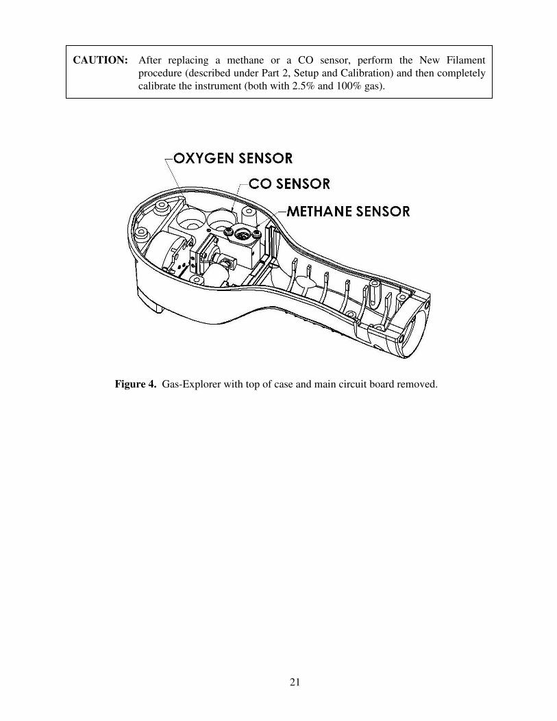
To install a new sensor or pump follow these steps while referring to figure 4:
1. Power OFF the instrument, remove the batteries, and with a box wrench unscrew the inlet port and filter assembly.
2. Remove the six recessed Phillips screws from the back of the instrument case and lift
the top cover off the case. Do not remove the two large Phillips screws flush with the back of the case, unless installing a new pump.
3. Place the instrument on a flat surface and remove the two Phillips screws located near the end of the handle. Carefully lift the circuit board out of the case.
4. If the methane sensor is to be replaced, remove the two Phillips screws holding the old sensor and unplug the 8 pin connector on the end of the sensor cable. Replace the old sensor with the new and connect and secure as before.
5. The oxygen and CO sensors are replaced by unplugging the old sensor from the circuit board, recovering the black gasket on the end of the sensor and replacing it in the sensor well, and inserting the new sensor into the sockets on the circuit board.
6. The pump is replaced by removing the two large Phillips screws flush with the back of the case (see Step 2 above), removing the manifold from the bottom of the case, and unscrewing the four screws which secure the pump gasket, pump plate, diaphragm, and piston to the manifold. Usually replacing the pump plate is sufficient to restore operation. Reverse the process for reinstallation.
7. The pump motor can be replaced by following the procedure in Step 6 and then removing the four Phillips screws which secure the pump motor to the mounting bracket. Reverse the process with the new motor.
8. Verify that the manifold, methane sensor, pump, and pump motor are securely mounted to the bottom of the case and the sensors appropriate to the instrument are plugged into the circuit board.
9. Align the cables to avoid the pump and guide the battery board into the two grooves on the left and right side of the handle. Lower the main circuit board until it rests on all the bosses.
10. Secure the two Phillips screws on the right and left side of the circuit board toward the end of the handle.
11. Replace the top cover of the case and secure it with the six Phillips screws.
12. Replace the inlet port and filter assembly with a box wrench and replace the batteries.
CAUTION: Crossed wires trapped between the main circuit board and the intake manifold will prevent the board from seating properly and may lead to intermittent contact of sensors with their sockets on the circuit board.
21
Figure 4. Gas-Explorer with top of case and main circuit board removed.
CAUTION: After replacing a methane or a CO sensor, perform the New Filament procedure (described under Part 2, Setup and Calibration) and then completely calibrate the instrument (both with 2.5% and 100% gas).

22
ACCESSORIES AND SPARE PARTS
Description Part Number
1. Probes and Hoses
Gooseneck Probe with Quick Connect and Filter (14 inch long) ................................... GP - 514
Surface Probe (with Quick Connect and Cone) ............................................................. SP - 636
Ceiling/Bar Hole Probe & Rubber Tip (34 inch long, clear) ......................................... BP - 034
Clear Bar Hole Probe (34 inch long, clear, side holes) .................................................. BP - 134
Fiberglass Bar Hole Probe (36 inch long, no side holes) ............................................... BP - 136
Fiberglass Bar Hole Probe (36 inch long, side holes) .................................................... BP - 236
Metal Bar Hole Probe (36 inch long, side holes) ........................................................... BP - 536
Standard Flue Gas Probe & Filter (10 inch long) .......................................................... FP - 110
Heavy Duty Flue Gas Probe & Filter ............................................................................. FP - 112
Straight Hose with Quick Connect Fitting (5 ft. long) ................................................... SQ - 060
2. Filters
Dust & Water-block Filter (5/pkg) ................................................................................. WF - 505
Water-stopper (with push-button release) ...................................................................... WS - 001
Dust Stopper (with replaceable filter) ............................................................................ DS - 001
Replacement Dust Filters (5/pkg) .................................................................................. DF - 105
Flue Gas Filter (5/pkg) ................................................................................................... FF - 005
Extended Duty Flue Gas Filter (5/pkg) .......................................................................... FF - 105
Heavy Hydrocarbon Filter (5/pkg) ................................................................................. HF - 005
Inlet Filter & Quick Connect Air Intake (5/pkg) ............................................................ IF - 705
3. Sensors
Methane Sensor (in flame arrestor) ................................................................................ MS - 601
CO Sensor ...................................................................................................................... CO - 301
Oxygen Sensor ............................................................................................................... OS - 501
4. Replacement Parts, and Manual
Pump Motor ................................................................................................................... PM - 501
Pump Head, Diaphragm/Plunger Assembly (5 sets/pkg) ............................................... PD - 505
Intake Manifold with Pump ........................................................................................... RM - 501
Battery Compartment Cap .............................................................................................. BC - 501
Operating Manual .......................................................................................................... OM - 0108
5. Instrument Case
Instrument Case w/Ethafoam Insert ............................................................................... IC - 501
6. Accessories for Calibration & Maintenance
Manual Calibration Apparatus (with MC-620 & FR-401) ............................................. PCA - 302
Methane & CO Calibration Gas (2.5% methane & 100 ppm CO, 620 liters) ............... MC - 620
On-demand Regulator for MC-620 ................................................................................ FR - 401
Rechargeable C-Sized Batteries (NiMH, 4/pkg) ............................................................ NM - 504
Rapid Charger for 2 to 4 C-Sized Batteries.................................................................... RC - 504
Prices and Terms
Prices and specifications are subject to change without notice. Prices are U.S. dollars. Orders are subject to acceptance and are FOB Norwood, Massachusetts. Payment terms are Net 30 days. Minimum order is $50.