Embed Size (px)
Citation preview

INSTRUCTIONS
& IMAGING HARDWARE FOR
LIFE SCIENCE MICROSCOPY
This instruction manual describes the hardware components of the Olympus and Imaging Stations. To ensure safety, obtain optimum performance and familiarize yourself fully with the use of these products, we recommend that you study this manual thoroughly before operation. Together with this manual, please also read the and software manual and the instruction manual of the microscope in order to understand overall operation methods. Retain this manual in an easily accessible place near a system for future reference.
®

OLYMPUS SOFT IMAGING SOLUTIONS GMBH Rupert-Mayer-Strasse 44 D-81379 München Tel: +49 89 - 89 55 805 660 Fax +49 89 - 89 55 805 6606 Email: [email protected]
www.olympus-sis.com

Imaging Excellence
We at Olympus Soft Imaging Solutions GmbH have tried to make the information in this manual as accurate and
reliable as possible. Nevertheless, Olympus Soft Imaging Solutions GmbH disclaims any warranty of any kind,
whether expressed or implied, as to any matter whatsoever relating to this manual, including without limitation
the merchantability or fitness for any particular purpose. Olympus Soft Imaging Solutions GmbH will from time
to time revise the software described in this manual and reserves the right to make such changes without obliga-
tion to notify the purchaser. In no event shall Olympus Soft Imaging Solutions GmbH be liable for any indirect,
special, incidental, or consequential damages arising out of purchase or use of this manual or the information
contained therein.
No part of this document may be reproduced or transmitted in any form or by any means, electronic or me-
chanical, for any purpose, without the prior permission of Olympus Soft Imaging Solutions GmbH.
2003 – 2009 by Olympus Soft Imaging Solutions GmbH. All rights reserved.
Manual version: March 2009

ΧΧΧΧ Declaration of Conformity
Robert-Koch-Strasse 9
D-82152 Planegg
declares under its own responsibility that the following products
Imaging Station for Life Science Applications
and
Imaging Station for Life Science Applications
to which this declaration refers are in conformity with the
Low Voltage Directive 73/23/EEC
and the
EMC Directives 89/336/EEC and 93/68/EEC
and the following standards:
EN 61010-1: 2001 (Low Voltage)
EN 61326:1997 + A1: 1998 + A2: 2001 (EMC).
Michael Czempiel and Dr. Matthias Seel, Managing Directors
June 11, 2003 and October 08, 2005

& Hardware Manual Contents
Contents
1 Introduction and Overview .................................................................................1 1.1 Abstract .............................................................................................................. 2 1.2 Technical Support ............................................................................................... 2 1.3 Symbols .............................................................................................................. 3 1.4 Checklist: cell^M / cell^R Components................................................................. 4 1.4.1 Standard Components: ....................................................................................... 4 1.4.2 Additional Components....................................................................................... 5
2 Illumination System MT10 / MT20.......................................................................7 2.1 Safety Precautions and Handling Instructions...................................................... 8 2.1.1 MT20 / MT10 Safety Precautions ......................................................................... 8 2.1.2 Special Safety Precautions Regarding the Arc Burners......................................... 9 2.1.3 Handling Instructions and Recommendations.................................................... 10 2.1.4 Safety Labels......................................................................................................11 2.2 Illumination System MT10 / MT20 Overview...................................................... 12 2.2.1 The Front Panel ................................................................................................. 12 2.2.2 Top: the Burner Flap...........................................................................................13 2.2.3 Right Side: the Filter Wheel Flap.........................................................................13 2.2.4 The Back Panel.................................................................................................. 14 2.2.5 Operation.......................................................................................................... 14 2.2.6 Specifications and Technical Data of the MT10 / MT20 .......................................15 2.2.7 Fuse Exchange .................................................................................................. 16 2.2.8 Specifications and Technical Data of the Real-Time Controller /
System Coordinator Connectors........................................................................ 16
3 Epi-Fluorescence Illuminators ........................................................................... 17 3.1 Features ............................................................................................................ 18 3.1.1 Light Guide Port ................................................................................................ 18 3.1.2 Adjustment Screws for Centering the Field of Illumination ................................ 18 3.1.3 Filter Slider for Dispersion Filter and Exciter Balancers ...................................... 19 3.1.4 Light Sensor ...................................................................................................... 19 3.2 IX2 Illuminators with Field Stop Slider ............................................................... 19 3.3 Flange for the IX2 Microscopes .......................................................................... 20 3.4 Fluorescence Illuminator Unit for the BX2 Microscopes: BX_MTA, BX_MTAA.... 20 3.5 Fluorescence Illuminator Unit for the MVX Microscope...................................... 21
4 System Assembly and Adjustment.................................................................... 23 4.1 Overview: Connectivity of System Components ................................................ 24 4.2 Connecting the Modules of the cell^M / cell^R Imaging Station ......................... 25 4.2.1 Connecting the MT10 / MT20............................................................................. 25 4.2.2 Mounting and Connecting the Epi-Fluorescence Illuminator .............................. 26 4.2.3 Connecting the Camera......................................................................................27 4.2.4 Connecting the Imaging PC to the Modules ....................................................... 28

Contents
4.2.5 Configuring the Imaging PC Network Connections ............................................29 4.3 Preparing the Illumination System MT10 / MT20................................................ 30 4.3.1 Burner Installation and Exchange....................................................................... 30 4.3.2 Burner Alignment .............................................................................................. 31 4.3.3 Filter Exchange .................................................................................................. 33 4.4 Centering the Illumination ................................................................................. 35 4.5 Optimizing the Illuminator Tube Position........................................................... 36
5 Optional Hardware Modules ............................................................................. 39 5.1 Mounting and Connecting the Piezo-Electric Objective Drive (PIFOC)................ 41 5.2 Connecting the Piezo-Electric Nosepiece Drive (Nosepiece PIFOC for
IX2 Microscopes)................................................................................................ 43 5.3 Connecting the Corvus Controller of a Motorized Märzhäuser Stage..................44 5.4 Installing Illuminators with Pinhole Field Stop Sliders......................................... 45 5.4.1 Centering the pinhole ........................................................................................46 5.5 Installing the OptiGrid ....................................................................................... 47 5.5.1 The OptiGrid Illuminator.................................................................................... 47 5.5.2 Connecting the OptiGrid.................................................................................... 47 5.5.3 Configuring the OptiGrid ...................................................................................48 5.5.4 Optical Alignment of OptiGrid and Camera........................................................49 5.5.5 Calibrating the OptiGrid..................................................................................... 50 5.5.6 Calibrating the OptiGrid Z-Position for Different Image Types ........................... 52 5.5.7 Stripe Filter for Snapshots ................................................................................. 54

& Hardware Manual Chapter 1 – Introduction and Overview 1
1 Introduction and Overview
Thank you very much for purchasing Olympus’ state of art Imaging Station cell^M or cell^R and for your confi-
dence in our products and service. It is Olympus main objective to provide you with solutions able to meet your
experimental demands and thus pave the way to your scientific success.
1.1 Abstract .............................................................................................................. 2 1.2 Technical Support ............................................................................................... 2 1.3 Symbols .............................................................................................................. 3 1.4 Checklist: cell^M / cell^R Components................................................................. 4 1.4.1 Standard Components: ....................................................................................... 4 1.4.2 Additional Components....................................................................................... 5

2 Chapter 1 – Introduction and Overview
1.1 Abstract
The Imaging Station cell^M / cell^R consists of the following hardware components:
— Illumination System MT10 / MT20
— Illumination Coupling to the microscope (epi-fluorescence illuminator with light fiber)
— Real-time Controller (cell^R) / System Coordinator (cell^M)
— controller board inside PC
— CCD camera (several models optional)
— Optional peripherals such as piezo-electric z-drive (PIFOC)
You will find a detailed description of these components, handling and alignment instructions as well as advice
how to maintain the performance of your system on the following pages. Keep in mind that all the components
are designed to work together as an integrated system. Taking away or replacing single components without
prior consultation of Olympus BioSystems is strongly discouraged and will most probably impair the perform-
ance of the system dramatically. Any damages to the system due to such mishandling will not be covered by the
guarantee.
All necessary tools for handling and alignment are shipped with the system.
The Imaging Station cell^M / cell^R is compatible with the following Olympus microscopes: IX50, IX70, IX51,
IX71, IX81, BX50, BX50WI, BX51, BX51WI, BX61, BX61WI. Other microscopes may be supported on request.
An additional installation of a standard Olympus epi-fluorescence Xe, Xe/Hg or Hg lamp house (e.g.,
U-LH100HGAPO, U-LH75XEAPO) is not possible because the OBS epi-fluorescence illuminator occupies the
microscope’s fluorescence excitation port.
This instructions manual is for the hardware components of the Olympus BioSystems Imaging Station cell^M /
cell^R. To ensure safety and optimum performance as well as to familiarize yourself with the use of the system
we recommend you to study this manual thoroughly before operating the system. Keep this manual in an easily
accessible place near the Imaging Station for future reference.
The cell^M / cell^R system meets the CE, UL and FCC requirements.
IEC/EN 61010-1(2nd
ed.), UL61010-1,
EN61326 Class A, FCC Part 15 Class A (Illumination System MT10 / MT20: class A and B).
1.2 Technical Support
If you find any information missing in this manual or you need additional support, please contact your local
Olympus representative.

& Hardware Manual Chapter 1 – Introduction and Overview 3
1.3 Symbols
The following symbols are placed on the Illumination System MT20 / MT10. Study the meaning of the symbols
and always use the equipment in the safest possible manner.
General symbols
Symbol Explanation
Carefully read the instructions on the label and the manual before use. Improper use could result
in personal injury to the user and/or damage the equipment.
The surface becomes hot and should not be touched with bare hands
Parts may be under high voltage and should not be touched.
The main switch is turned OFF.
The main switch is turned ON.
This symbol indicates separate collection of waste electrical and electronic equipment in the EU
countries.
Do not throw the equipment into the domestic refuse
Please use the return and collection systems available in your country for the disposal of this
product

4 Chapter 1 – Introduction and Overview
1.4 Checklist: cell^M / cell^R Components
Before assembly, please check whether you have the complete set of cell^M / cell^R system components as
listed below.
1.4.1 Standard Components:
a Microscope, upright or in various configurations.
b Illumination System MT10 / MT20 consisting of:
— MT10 / MT20 housing with integrated lamp house, filter wheel, shutter and attenuator
— short arc burner
— power cord
— Illumination System connector cord (blue RJ45 cable)
— light sensor connector cord (see photo in Chapter 7, System Assembly and Adjustment)
— optical fiber (quartz light guide; see photo in Chapter 7, System Assembly and Adjustment)
— set of hex-wrenches
— cotton gloves
c Fluorescence filter set consisting of:
— Dichroic mirror and emission filter mounted in Olympus filter cube
— Excitation filter(s) to be mounted in the MT10 / MT20 filter wheel
d MT10 / MT20 epi-fluorescence illuminator to couple the illumination system to the microscope via the optical
fiber
e CCD camera (or EMCCD camera) of choice, typically with
— FireWireTM
(IEEE 1394) cable
— trigger cable
f cell^R / cell^M imaging computer including
— cell^R Real-time Controller board / cell^M System Coordinator board
— cell^R / cell^M network card
— FireWireTM
(IEEE 1394) card
— front panel with three digital I/O ports (optional for cell^M)
— cell^R / cell^M imaging software installed
— computer monitor with cable
— 2 power cords
— software protection key (dongle)
g cell^R / cell^M imaging software on CD-ROM
h Manuals

& Hardware Manual Chapter 1 – Introduction and Overview 5
1.4.2 Additional Components
The following components are optional and may or may not be part of your cell^R / cell^M imaging workstation.
a Motorized microscope modules in various configurations; all include
— universal microscope control box (UCB)
— microscope manual control (optional)
— power cord
— connection cords
b Fast piezo-electric objective mover (PIFOC, Physik Instrumente GmbH, see Chapter 5.1, Mounting and Con-
necting the Piezo-Electric Objective Drive PIFOC) consisting of
— Objective mover
— PIFOC controller
— power cord
— PIFOC connector cable
— spacers to lift the stage (for Olympus IX microscopes)
— objective distance rings
— extension cords
c Fast piezo-electric nosepiece mover (nosepiece PIFOC, Physik Instrumente GmbH, see Chapter 5.2, Mount-
ing and Connecting the Piezo-Electric Objective Drive PIFOC) consisting of
— nosepiece mover
— nosepiece PIFOC controller
— power cord
— PIFOC connector cable
— extension cords
d motorized stage by different manufacturers
e climate chamber
f Optigrid for resolution enhancement via structural fluorescence illumination

6 Chapter 1 – Introduction and Overview

& Hardware Manual Chapter 2 – Illumination System MT20 / MT10 7
2 Il lumination System MT10 / MT20
This chapter refers only to the fluorescence Illumination System MT10 / MT20. Before using this unit together
with the other system components, the microscope and associated devices, make sure that you have carefully
read and understood their respective manuals, and understand how the entire system should be operated.
2.1 Safety Precautions and Handling Instructions...................................................... 8 2.1.1 MT20 / MT10 Safety Precautions ......................................................................... 8 2.1.2 Special Safety Precautions Regarding the Arc Burners......................................... 9 2.1.3 Handling Instructions and Recommendations.................................................... 10 2.1.4 Safety Labels......................................................................................................11 2.2 Illumination System MT10 / MT20 Overview...................................................... 12 2.2.1 The Front Panel ................................................................................................. 12 2.2.2 Top: the Burner Flap...........................................................................................13 2.2.3 Right Side: the Filter Wheel Flap.........................................................................13 2.2.4 The Back Panel.................................................................................................. 14 2.2.5 Operation.......................................................................................................... 14 2.2.6 Specifications and Technical Data of the MT10 / MT20 .......................................15 2.2.7 Fuse Exchange .................................................................................................. 16 2.2.8 Specifications and Technical Data of the Real-Time Controller /
System Coordinator Connectors........................................................................ 16

8 Chapter 2 – Illumination System MT20 / MT10
2.1 Safety Precautions and Handling Instructions
For Laboratory Use Only.
Danger: Ultraviolet radiation is emitted from this product. Avoid exposure. ALWAYS WARE
PROTECTIVE CLOTHING. EXPOSURE MAY CAUSE PREMATURE AGING OF THE SKIN AND
CANCER. ALWAYS WARE PROTECTIVE EYEWEAR; FAILURE TO DO SO MAY RESULT IN SEVERE
BURNS OR LONG TERM INJURE TO THE EYE. Never look directly into the lamp. Exposure can
cause eye and skin allergy and allergic reactions. Medications or cosmetics may increase your sensi-
tivity to ultraviolet radiation. Consult a physician before operating this product if you are using
medications or have a history of skin problems or believe yourself particularly sensitive to sunlight.
Always have the microscope's UV cut plate mounted as protection against UV radiation.
Color fading of specimens: This system features high excitation light intensity to ensure bright ob-
servation of dim fluorescent specimens. Consequently, after longer periods of observations using
high-power objectives, the colors of specimens will fade quicker than usual, causing the intensity
and contrast of fluorescent images to deteriorate. In such cases it is advisable to reduce excitation
light intensity to slow down color fading. To reduce the light intensity use the built-in attenuator as
explained in this manual.
Engage the shutter of MT20 / MT10 as explained in this manual (or use the shutter of the micro-
scope) even if you interrupt observation only for a short time.
2.1.1 MT20 / MT10 Safety Precautions
a Always use a power cord provided or approved by Olympus BioSystems.
b Provide unimpaired access to the main power switch at the rear panel.
c No electrical cord should be connected or disconnected while the power switch is set on (“I”). Make sure that
the unit's main power switch is set off (“O”) before plugging or unplugging the power cord to the power out-
let.
d Always make sure that the grounding terminal of the Illumination System MT10 / MT20 and the wall outlet
are connected properly. If the System is not grounded, Olympus BioSystems cannot warrant the electrical
safety and performance of the system.
e When installing the Illumination System MT10 / MT20 leave at least 100 mm free air space at the rear panel
and at least 50 mm at the sides and on top to allow air circulation. The Illumination System MT10 / MT20 has
an internal fan to cool the arc burner. The air outlet is located at the rear of the housing while the inlet grid is
at the bottom.

& Hardware Manual Chapter 2 – Illumination System MT20 / MT10 9
f The Illumination System MT10 / MT20 must be placed on an even, stable and flat surface and standing on its
supports. Make sure that no cloth or paper can clog the air inlet slits at the bottom of the housing.
g The arc burner has to be exclusively one of the two types specified by Olympus BioSystems. No other arc
burner may be used with the Illumination System MT10 / MT20.
h Do not open the burner flap of the Illumination System MT10 / MT20 while the arc burner is turned on. First
turn off the arc burner by software and wait for at least 30 minutes while the cooling fan is operating. Set the
main power switch on “O” (OFF) before opening the burner flap. The arc burner socket and all parts in the vi-
cinity of the burner will be extremely hot during operation and will cause thermal injury if touched.
i Never attempt to disassemble the Illumination System MT10 / MT20 or to open its housing. The internal
power supply units and electrical circuits contain high voltage components and can cause severe electrical
shock and thus are not serviceable by the user. Warranty will be lost if the housing is opened.
j Do not operate the Illumination System MT10 / MT20 under environmental conditions other than specified in
this manual (see Chapter 2.2.6, Specifications and Technical Data).
k Do not look directly into the light emitted by the arc burner with unprotected eyes under any circumstances.
The emitted light is very intense and has a very high UV-content that may cause irreversible damage to your
eyes.
l Avoid direct exposure of unprotected skin to the light emitted by the arc burner. It can cause severe burns.
m Direct exposure to the arc burner light may occur at the following positions:
— Illumination System’s housing at the fiber port if the fiber is removed
— Exit of the optical fiber
— Exit of the illumination coupling (epi-fluorescence illuminator)
— Beam path of the microscope (which upon proper usage is not accessible by the user)
— Exit of the objective (or at the nose piece, if no objective is mounted)
n If the equipment is used not as specified by this manual, the safety and performance of the equipment may
be impaired. In addition, the equipment may also be damaged and warranty may be lost. Always use the
equipment as outlined in this instruction manual.
2.1.2 Special Safety Precautions Regarding the Arc Burners
a Handling the arc burner bulb is potentially dangerous. Wear a protective mask, leather gloves and a thick
long-sleeved shirt or coat during handling and disposal (see below).
b The arc burner bulb is under high internal pressure. Do not hit the arc burner bulb against anything nor
scratch it or apply excessive stress. Avoid vibrations. Otherwise the arc burner bulb could explode and cause
injuries.
c For transport and storage always place the arc burner in the provided protective case.
d Take care to avoid leaving fingerprints or dirt on any part of the high-pressure arc burners. If contaminated,
clean by wiping gently with gauze. To remove fingerprints or oil stains, wipe with gauze slightly moistened
with lens cleansing fluid.
Since these fluids are highly inflammable, be careful to keep them away from open fire, heat or hot surfaces
and potential sources of electrical sparks, such as main switches.

10 Chapter 2 – Illumination System MT20 / MT10
e The arc burners have an average lifetime as specified in this manual (see Chapter 2.2.6, Specifications and
Technical Data). When the arc burner hour counter (see Chapter 4.3.2, Burner Alignment) gives a reading
higher than the specified lifetime, replace the burner with a new one following the instructions for replace-
ment (see Chapter 4.3.1, Burner Installation and Exchange) and disposal of used burners (see below). Arc
burners that are used longer than the rated service lifetime will have a reduced intensity and stability; they
are likely to fail and might explode because of the deteriorated glass condition.
f Arc burners not in service must always be kept in the provided protective case.
g Hg/Xe burner bulbs contain poisonous mercury. They have to be treated with special care. If they explode
during service mercury gas might be dispersed in the environment.
h Hg/Xe burners must be treated as hazardous waste. Always follow national and local laws and guidelines
when disposing of Hg/Xe burners. It is recommended to commission a professional waste disposal company
with the disposal. Hand over the burner in its original packaging.
i Xe burners: It is recommended to commission a professional waste disposal company with the disposal.
Hand over the burner in its original packaging. Disposal without breaking the glass part may result in burner
bulb explosion. Follow the instructions below to prevent harmful repercussions.
— Ware protective clothing.
— Wrap the used lamp in a thick cloth.
— Break the glass part of the lamp into pieces using a hammer.
— Dispose of as industrial waste (except Hg/Xe burners, see above).
2.1.3 Handling Instructions and Recommendations
a The Illumination System MT10 / MT20 is a precision instrument. Handle it with great care and avoid subject-
ing it to sudden or severe impact. Also connect each cable gently.
b The built-in ventilating fan and the built-in filter wheels may generate vibrations and sound. Therefore it is
recommended not to place the Illumination System MT10 / MT20 on the same table as the microscope.
c With exception of the burner flap and the filter flap the Illumination System MT10 / MT20 may only be
opened and disassembled by authorized service personal. Otherwise warranty is lost.
d Before using the Illumination System MT10 / MT20 for the first time check that the burner is installed cor-
rectly and that all cords are connected correctly.
e Before opening the burner flap for replacement of the burner, turn it off by software (cell^R / cell^M or OBS
System Configuration) and wait for at least 30 minutes while the cooling fan is operating. Then set the main
power switch on “O” (OFF) and open the burner flap. (Do not open the burner flap of the Illumination System
MT10 / MT20 while the arc burner is turned on.)
f Do not place the unit inside a climate chamber.
g Do not bend the optical fiber to a diameter of less than 45 cm. The optical fiber is fragile and may brake if
bent too strongly or if torsional stress is applied.
h Cover the ends of the optical fiber with the protection cover if they are not attached to the Illumination Sys-
tem MT10 / MT20 or to the microscope.

& Hardware Manual Chapter 2 – Illumination System MT20 / MT10 11
i Always operate the Illumination System MT10 / MT20 in an upright position. Never lay it on the side during
operation. This could cause the lamp to burst, damage the equipment and cause injury.
j Before transport of the system remove the lamp and store it safely in the provided protective case.
k Mind that turning the arc burner on and off repeatedly will shorten the life span.
l To clean the surface of the Illumination System MT10 / MT20, use a lint-free, dry and soft cloth. Never at-
tempt to use organic solvents or strong detergents.
m Take care to avoid leaving fingerprints or dirt on the optical filters, the lenses at the ends of the light guide or
the optics of the illumination coupling. If contaminated, clean by wiping gently with special optical cleansing
tissue. To remove fingerprints or oil stains, wipe with special optical cleansing tissue slightly moistened with
lens cleansing fluid. Use the cotton gloves when handling light filters.
* Since these fluids are highly inflammable, be careful to keep them away from open fire, heat or hot sur-
faces and potential sources of electrical sparks, such as main switches.
2.1.4 Safety Labels
The following symbols are found on the Illumination System MT10 / MT20. Study the meaning of the symbols
and always use the equipment in the safest possible manner.
Lamp housing safety label
Label Note Location
Carefully read the
instructions on the
label and the
manual before use.
Improper use could
result in personal
injury to the user
and/or damage the
equipment.
Top side of
the Illumina-
tion System
MT20 / MT10
Fiber port safety label
Label Note Location

12 Chapter 2 – Illumination System MT20 / MT10
Carefully read the instructions on the
label and the manual before use.
Improper use could result in personal
injury to the user and/or damage the
equipment.
Front side of the
Illumination
System MT20 /
MT10
2.2 Illumination System MT10 / MT20 Overview
2.2.1 The Front Panel
LOCK: 2 mm hex-wrench opening to lock or release the arc burner for installation and replacement.
BURNER ADJUSTMENT: three handles to align the burner.
BURNER ON LED: On / off arc burner on / off
CONTROLLER connector, MT20 only: RJ45 plug to connect the Illumination System MT20 to the cell^R Real-
Time Controller.
ODB connectors (two), MT10 only: OBS Device Bus plug to connect the Illumination System MT10 to the
cell^M System Coordinator.
FIBER LOCK: 1.5 mm hex-wrench opening to lock or release the optical fiber in the fiber port.
FIBER lock
Fiber
port
LED:
Status
AUXILIARY
connector (MT20 only)
Light sensor
connector
LOCK
LED:
BURNER ON
CONTROLLER
connector
BURNER
ADJUSTMENT

& Hardware Manual Chapter 2 – Illumination System MT20 / MT10 13
Fiber port: Opening for the optical fiber.
LIGHT SENSOR connector: 3-pin connector for light sensor cable.
AUXILIARY connector (MT20 only): 15-pin sub-D port, currently without use.
STATUS LED: Off no connection to cell^R Real-Time Controller / cell^M System Coordinator.
On active connection to cell^R Real-Time Controller / cell^M System Coordinator, ready for operation.
Regular flashing Illumination System MT10 / MT20 in stand-by mode.
Irregular activity Illumination System MT10 / MT20 in action.
2.2.2 Top: the Burner Flap
Before opening: Wait until system has cooled down, then switch main power off!
2.2.3 Right Side: the Filter Wheel Flap
The flap has to be closed and the subsequent automatic initialization has to be completed for op-
eration.
Opening for a 3 mm hex-
wrench
Access to the arc burner
for replacement

14 Chapter 2 – Illumination System MT20 / MT10
Arc burner cooling air
outlet
Main power switch, fuse-holder
and AC power input connector.
2.2.4 The Back Panel
Do not block ventilation slits! Keep 10 cm distance from wall.
2.2.5 Operation
Only operate the system when completely installed and connected to a microscope.
For operating set main power switch on “I” (ON). By doing so the System will execute a routine to initialize and
test the electro-mechanical components and motors.

& Hardware Manual Chapter 2 – Illumination System MT20 / MT10 15
For further operation run the cell^R / cell^M software or the OBS System Configuration on your computer ac-
cording to the software manual.
2.2.6 Specifications and Technical Data of the MT10 / MT20
Dimensions and weight: H 354 x W 236 x D 315 mm, 13 kg
Power supply rating: 100 to 120 V and 200 to 240 V AC, 50 – 60 Hz (47 – 63 Hz), 4.0 / 2.1A
Fuse: 250VAC, T4AH (5 x 20mm)
Enclosure rating: IP20
Short arc burner:
— Type 1: 150 W Xe, high-pressure arc burner, Olympus _MT_ARC/XE, article No. E0435001, expected
minimal lifetime under standard laboratory conditions: 1000 h
— Type 2: 150 W Hg/Xe, mixed gas arc burner, Olympus _MT_ARC/HG, article No. E0435002, expected
minimal lifetime under standard laboratory conditions: 1000 h
Light output range, MT10 / MT20: between 320 and 720 nm; MT10_NIR / MT20_NIR: between 380 and 800 nm
Light output power: up to 50% higher for MT10E / MT20E as compared to MT10 / MT20
Mechanical shutter: opening/closing time MT20 1.0 +/- 0.2 ms, MT10 < 5 ms
Filter wheel: 8 positions
Optical filter dimensions: ∅ 24.8 mm +/- 0.1, thickness 2 – 6 mm, maximum weight 7 g each
Filter and attenuator switching time: This is dependent on the filter load and the number of positions to be
moved.
Switching times
MT20 [ms] MT10 [ms]
Load [g] < 10.5 < 21 > 21 > 28 > 35 attenuator < 10.5 < 21 > 21 > 28 > 35 attenuator
Next position 58 64 72 80 91 35 85 103 115 125 135 85
2nd
position 86 92 102 114 129 40 141 158 170 181 194 133
3rd
position 113 119 130 142 158 50 196 213 225 236 249 149
4th
position 141 147 157 169 186 60 etc. 251 269 281 292 304
Attenuator transmission [%]
— MT20, 14 positions: 1, 3.1, 6.3, 10, 12.5, 25, 33.3, 37.5, 50, 62.5, 66.6, 75, 87.5, 100
— MT10, 7 positions: 3.1, 10, 25, 37.5, 62.5, 75, 100
LED indicators, MT10 / MT20 front: BURNER ON (lower left), STATUS (lower center)
Connectors, MT20 front:
— CONTROLLER: RJ45 connection to Real-Time Controller board (PC back panel)
— AUXILIARY: sub-D, 15-pin connection (MT20 only)
— LIGHT SENSOR: 3 pin connection to light sensor (epi-fluorescence illuminator)
Connectors, MT10 front:
— ODB: ODB Device Bus connection to System Coordinator board (PC back panel)
— LIGHT SENSOR: 3 pin connection to light sensor (epi-fluorescence illuminator)

16 Chapter 2 – Illumination System MT20 / MT10
Connectors, MT10 / MT20 rear:
— 3-pin AC input plug with ground
— Main switch (I: on, O: off)
Optical fiber: minimum bend diameter 45 cm short term, avoid torsional stress
— Type 1: 2 m solid quartz fiber, Olympus MT-FIB/2m, article No. E0435007
— Type 2: 3 m solid quartz fiber, Olympus MT-FIB/3m, article No. E0435008
Operating environmental conditions: indoor use only.
— Altitude: up to 2000 m
— Ambient temperature: 5 to 40°C
— Maximum relative humidity: 80% up to 31°C, 70% at 34°C, 60% at 37°C, 50% at 40°C
— Supply voltage fluctuation: +/- 10%
— Pollution degree 2 (in accordance with IEC664)
— Over-voltage category II (in accordance with IEC664)
2.2.7 Fuse Exchange
During standard operation the fuses will not blow. In case the fuse blows switch off the unit and contact your
local Olympus service specialist or the Olympus BioSystems support team to avoid potential hazard because the
unit might be severely damaged.
The system is equipped with 2 fuses (high breaking, delayed action fuse, 250 V AC, 4 A, size: 5 x 20 mm) located
below the main switch of the Illumination System MT20 / MT10 at the rear of the housing.
2.2.8 Specifications and Technical Data of the Real-Time Controller / System Coordina-
tor Connectors
Connectors, cell^R / cell^M Imaging Computer, front, DIGITAL I/O:
— Input: R(in) > 10 kΩ, low V < 0.8 V, high V > 2.0 V,
— Output, low level: R(out) < 90 Ω, V < 0.8 V @ I < 5.8 mA
Output, high level: R(out) < 870 Ω, V > 2.2 V @ I < 3.2 mA
If a high level voltage of 5 V is required, please contact your local support specialist.
Camera Trigger: open collector with 330 Ω pull-up to 5 V
— TTL high level: R(out) = 330 Ω, V > 2.0 V @ I < 9 mA — TTL low level: R(out) < 90 Ω, V < 0.8 V @ I < 9 mA
PIFOC controller (analog out): SMB, 14 Bit DAC, V = 0 – 10 V (±2 mV) @ 1 MΩ R(load),
I < 1 mA, R(out) = 47 Ω @ DC, suggested R(load) > 50 KΩ

& Hardware Manual Chapter 3 – Epi-Fluorescence Illuminators 17
3 Epi-Fluorescence Il luminators
The optical design of the epi-fluorescence illuminators is identical for all microscopes supported. For the two
Olympus IX series (IX50 and IX70 vs. IX51, IX71 and IX81) different flanges have to be used to mount the illumina-
tors on the microscope frames. For the two BX series (BX50 and BX50WI vs. BX51, BX51WI, BX61 and BX61WI)
the illuminators are connected to the respective special reflective Olympus illuminators for fiber coupling.
3.1 Features ............................................................................................................ 18 3.1.1 Light Guide Port ................................................................................................ 18 3.1.2 Adjustment Screws for Centering the Field of Illumination ................................ 18 3.1.3 Filter Slider for Dispersion Filter and Exciter Balancers ...................................... 19 3.1.4 Light Sensor ...................................................................................................... 19 3.2 IX2 Illuminators with Field Stop Slider ............................................................... 19 3.3 Flange for the IX2 Microscopes .......................................................................... 20 3.4 Fluorescence Illuminator Unit for the BX2 Microscopes: BX_MTA, BX_MTAA.... 20 3.5 Fluorescence Illuminator Unit for the MVX Microscope...................................... 21

18 Chapter 3 – Epi-Fluorescence Illuminators
3.1 Features
The MT20 / MT10 epi-fluorescence illuminator (MT_CON) is a tube which houses the different lenses and fea-
tures the fiber port, the filter slider, the adjustments screws to center the field of illumination and the light sen-
sor to measure the light output during the optimization of the lamp position in the MT20 / MT10. These items
are referred to in detail below.
1: illuminator tube containing the optical elements
2: light guide with fiber connector and ring to adjust
depth of penetration for focus optimization
3: light guide port
4: set screw to fix the light guide
5: light sensor with cable
6: adjustment screws for centering the field of
illumination
7: filter slider with dispersion filter
8: flange for IX2 microscope frame (IX2_RFA)
9: screw to fix the illuminator tube inside the flange
Optionally the illuminator may have a space-saving L-shape form for the IX2 microscopes. Furthermore, a dual-
port illuminator is available for the IX2 microscopes.
3.1.1 Light Guide Port
The light guide features a distance ring that assures the optimum position of the fiber exit when the fiber is
moved all the way into the port. The position of the distance ring is set by Olympus BioSystems and fixed by a
small screw. The fiber exit is fixed inside the port by a form-fit screw. Thus, the fiber cannot be pulled out if the
fixing screw is just slightly loose.
3.1.2 Adjustment Screws for Centering the Field of Illumination
The illumination has to be centered in order to illuminate the entire chip of the CCD camera. No tool is needed to
turn the screws. See Chapter 7.4, Centering the Illumination.
8
1 2
3
6
6
4
7 5
9

& Hardware Manual Chapter 3 – Epi-Fluorescence Illuminators 19
3.1.3 Filter Slider for Dispersion Filter and Exciter Balancers
The slider has four openings to hold filters of 12 mm diameter. The first position contains a dispersion filter that
allows illuminating the entire ocular's field of view. One position should always remain free for unaltered light
throughput and illumination of the CCD chip with maximum brightness. The two other positions are empty by
default. They can be equipped with filters that are to be fixed by easily removable plastic rings.
3.1.4 Light Sensor
A light sensor (photodiode) is mounted inside the illuminator tube (but outside the light path) and measures the
intensity of back-scattered light. The more intense the scattered light, the higher the overall light intensity leav-
ing the fiber and the better correspondingly the position of the short arc burner in the MT20 / MT10 lamp house.
The light sensor cable is connected to a plug in the front plate of the MT20 / MT10.
3.2 IX2 Illuminators with Field Stop Slider
Certain fluorescence imaging techniques with intentional bleaching of fluorophores require exclusive illumina-
tion of a small region of the field of view. This can be realized with MT20 / MT10 illumination systems by using
illuminators that contain a field stop slider in the field plane. The slider can be equipped with pinhole inserts of
different diameter. Due to the pinhole that is projected into the focus plane only a circular region in the center of
the field of view is exposed to incident light.

20 Chapter 3 – Epi-Fluorescence Illuminators
3.3 Flange for the IX2 Microscopes
The MT_CON illuminators are inserted into special flanges (IX2_MTA, see photo in chapter 3.1) mounted on the
epi-fluorescence port of IX2 microscopes; see Chapter 4.2.2, Mounting and Connecting the Epi-Fluorescence Illu-
minator.
3.4 Fluorescence Illuminator Unit for the BX2 Microscopes: BX_MTA, BX_MTAA
1: illuminator tube containing the optical elements
2: flange
3: set screw to fix the illuminator
4:filter slider with dispersion filter
5: housing of filter cube turret unit identical to standard BX-RFA
or BX-RFAA fluorescence illuminator
A special flange mounted to the back of the housing of a modified BX-RFA or a modified, motorized BX-RFAA
illuminator unit hosts the illuminator tube in case of BX2 microscopes. The mounting to the microscope frame is
the same as described in the microscope manual for the unmodified BX-RFA or BX-RFAA units.
1 2
4
5
3

& Hardware Manual Chapter 3 – Epi-Fluorescence Illuminators 21
3.5 Fluorescence Illuminator Unit for the MVX Microscope
1: fluorescence illuminator MT_CON
2: flange IX2_MTA
3:filter slider with dispersion filter
4: housing of filter cube turret unit identical to standard
MVX_RFA fluorescence illuminator
The IX2_MTA flange can be mounted to the mirror unit housing of the MVX-RFA illuminator when the standard
direct light coupling optics are removed. The MT_CON illuminators can then be inserted and fixed as usual.
The mounting of the entire unit to the microscope frame is the same as described in the microscope manual for
the standard MVX-RFA unit.
1
2
4
3

22 Chapter 3 – Epi-Fluorescence Illuminators

& Hardware Manual Chapter 4 – System Assembly and Adjustment 23
4 System Assembly and Adjustment
The following chapters explain how all the different hardware modules of the cell^R / cell^M Imaging Stations
have to be connected for correct operation.
4.1 Overview: Connectivity of System Components ................................................ 24 4.2 Connecting the Modules of the cell^M / cell^R Imaging Station ......................... 25 4.2.1 Connecting the MT10 / MT20............................................................................. 25 4.2.2 Mounting and Connecting the Epi-Fluorescence Illuminator .............................. 26 4.2.3 Connecting the Camera......................................................................................27 4.2.4 Connecting the Imaging PC to the Modules ....................................................... 28 4.2.5 Configuring the Imaging PC Network Connections ............................................ 29 4.3 Preparing the Illumination System MT10 / MT20 ............................................... 30 4.3.1 Burner Installation and Exchange ...................................................................... 30 4.3.2 Burner Alignment...............................................................................................31 4.3.3 Filter Exchange...................................................................................................33 4.4 Centering the Illumination..................................................................................35 4.5 Optimizing the Illuminator Tube Position .......................................................... 36

24 Chapter 4 – System Assembly and Adjustment
4.1 Overview: Connectivity of System Components
The schematic diagram below shows the connection of standard components of the cell^R station. Before you
switch on any of the cell^R components, make sure that they are correctly connected.
1: Power cords
2: FireWire (IEEE 1394) cable to connect the CCD camera to the FireWire board of the computer for image data transfer.
3: Camera trigger line to connect the CCD camera to the computer-hosted cell^R Real-time Controller for synchronized image acqui-
sition.
4: Illumination System MT20 connection cable: Blue RJ45 cable to connect the MT20 to the computer-hosted cell^R Real-time Con-
troller / cell^M System Coordinator for (synchronized) control of the sample illumination.
5: Light sensor cable to connect the light sensor in the epi-fluorescence illuminator (to monitor the optimization of the illumination
intensity) to the LIGHT SENSOR connector at the front of the MT20 / MT10.
6: Optic quartz light: Blue fiber to guide the light from the MT10 / MT20 to the epi-fluorescence illuminator.
Do not bend the light guide to a radius of less than 45 cm; otherwise the quartz fiber may be dam-
aged.

& Hardware Manual Chapter 4 – System Assembly and Adjustment 25
4.2 Connecting the Modules of the cell^M / cell^R Imaging Station
4.2.1 Connecting the MT10 / MT20
1. Connect the power cord to the main power connector at the MT10 / MT20 rear panel and to a power
outlet. Caution: Make sure that the MT10 / MT20's main power switch is set on OFF before connec-
tion.
2. MT20: Connect the CONTROLLER connector at the front of the MT20 with the controller
board at the back of the PC using the blue RJ45 cable.
MT10: Connect the CONTROLLER connector at the front of the MT10 with the same type of 4-pin
Lemo plug at the back of the PC or another ODB device (e.g., IX2_FRFACA or U_FFWO) using an
ODB Device Bus cable.
3. Connect the LIGHT SENSOR connector with the light sensor in the epi-fluorescence illumina-
tor using the black light sensor cable (with small three-pin plugs).
4. Connect the light guide: Gently insert the thin connector of the optical fiber entirely into the fi-
ber port at the front panel. Keep the protective plastic caps for transport purposes.
The fiber is fragile and might break if handled without care.
— Do not bend the fiber more than to a diameter of 45 cm (short term: 35 cm).
— Do not expose the fiber to shear force or torque.

26 Chapter 4 – System Assembly and Adjustment
5. Lock the fiber by turning the fiber lock screw with a 1.5 mm hex wrench clockwise. Tighten the screw
gently.
6. For the connection of the other connector of the fiber see the following chapter.
UV radiation output; do NOT disconnect fiber while burner is switched ON.
4.2.2 Mounting and Connecting the Epi-Fluorescence Illuminator
For the BX2 microscopes the installation of the entire epi-fluorescence unit containing the MT20 / MT10 illumi-
nator is explained in the respective microscope manuals.
The IX2_MTA flanges is mounted to the microscope frame as follows (see also the photo in Chapter 3, Epi-
Fluorescence Illuminator):
1. Insert the flange with the dovetail 1 first all the way into the frame opening.
2. Fix it with the two screws in the two holes that point downward by 45° on the left and right side of
the frame using the 4 mm hex-wrench.
3. Insert the epi-fluorescence illuminator tube into the flange so that the distance between flange and
back end of the illuminator (light guide port) is as listed for the different objectives and in depend-
ence of an installed PIFOC (see Chapter 4.5, Optimizing the Illuminator Tube Position).
4. Fix the illuminator with the fixing screw 2 of the flange using the 2.5 mm hex-wrench.
5. Connect the female end of the light sensor cable.
6. Insert the thick end of the light guide as far as possible (until the ring to adjust the depth of penetra-
tion makes contact with the illuminator) and fix it with the fixing screw using the 2 mm hex-wrench.
The fiber cannot be pulled out if the form-fit fixing screw is just slightly loose.
1
2

& Hardware Manual Chapter 4 – System Assembly and Adjustment 27
UV radiation output; do NOT disconnect fiber while burner is switched ON.
4.2.3 Connecting the Camera
The camera has to be mounted on the microscope camera port using a c-mount adapter as described in the
microscope manual.
4.2.3.1 Camera Olympus XM10-T
1. Use the 3m FireWire cable to connect the FireWire port of the camera with the FireWire card at
the back of the computer.
2. Connect the trigger-out BNC port of the controller at the back of the computer to the trigger-in port
of the camera with the trigger cable. Note that both the camera plug of the cable and the camera
port are marked with a red dot, the two of which have to be lined up to enable the connection.
4.2.3.2 Camera Hamamatsu Orca R2
1. Make sure that the camera controller unit is switched off and disconnected from the power outlet.
2. Use the 3m FireWire cable to connect the FireWire port at the back of the camera controller unit
to the FireWire card at the back of the computer.
3. Connect the trigger-out BNC port of the controller at the back of the computer to the trigger-in BNC
port of the camera controller unit.
4. Connect camera and camera controller to the special multi-pin cable.

28 Chapter 4 – System Assembly and Adjustment
4.2.4 Connecting the Imaging PC to the Modules
1. Insert the cell^R / cell^M hardware key into one of the USB ports of the computer. In case your sys-
tem is equipped with a parallel dongle insert it into the parallel port.
2. MT20 (cell^R): Insert the blue RJ45 cable coming from the CONTROLLER plug on the MT20 front
panel into the central RJ45 port of the cell^R controller board.
3. MT10 (cell^M): Insert the 4-pin ODB Device Bus cable coming from the CONTROLLER plug on the
MT10 front panel into the Lemo plug of the cell^R controller board.
4. Camera: Connect the BNC plug of the trigger cable to the BNC port of the cell^R / cell^M controller
board.
5. Camera: Plug the FireWireTM
cable coming from the camera or the camera controller (in case of the
Hamamatsu Orca AGR) into any one of the two ports of the FireWireTM
card.
5 FireWire ports
1 USB port for
cell^M / cell^R
hardware key
2 Connection to
MT20
3 Lemo plug to
connect with
MT10 or other
ODB device
(U_FFWO or
IX2_FRFACA)
4 BNC port for
camera trig-
ger cable
6 SMB port for
PIFOC controller
cable
8 Controller serial
port for motorized
stage connection
7 Binder plug for
ODB device
power supply

& Hardware Manual Chapter 4 – System Assembly and Adjustment 29
6. PIFOC (optional): The SMB plug of the PIFOC controller cable coming from the PIFOC controller
(CONTROL INPUT) has to be connected to the corresponding port on the right hand side of the
cell^R / cell^M controller board.
In addition to the interfaces at the back the cell^R / cell^M imaging computer features a DIGITAL I/O interface
on the front panel. It contains seven BNC ports. The TTL OUT ports A, B and C enable to send TTL trigger pulses
to peripheral devices during an experiment. The DIGITAL I/O ports 1, 2, 3 and 4 serve the same purpose but they
can be defined additionally as TTL IN (trigger IN) ports in the cell^M / cell^R Experiment Manager.
4.2.5 Configuring the Imaging PC Network Connections
When the factory settings of the network connections to the cell^R Real-time Controller / cell^M
System Coordinator are changed, the communication will be lost and the Imaging Station cannot
be operated anymore.
It may happen that the settings of the network connections are changed, especially when the operating system
is upgraded or the imaging PC is hooked to an intranet. The following instructions allow resetting connection
settings.
1. Go to Control PanelNetwork Connections.
2. Make sure that the connection to the cell^R Real-time Controller / cell^M System Coordinator is
called CTR_R.
3. Go to PropertiesGeneral.
4. Make sure that Internet Protocol (TCP/IP) is activated and go to Properties.
5. Use the IP address 42.42.42.17 and the Subnet mask 255.255.255.0.
6. Confirm with OK. And go to the Advanced tab.
7. Make sure that the Window FirewallSettings are off.
8. Confirm with OK.

30 Chapter 4 – System Assembly and Adjustment
4.3 Preparing the Illumination System MT10 / MT20
4.3.1 Burner Installation and Exchange
Wear protective glasses, clothes and gloves. Avoid any kind of mechanical stress to the burner. Al-
low the illumination system to cool down for at least 30 minutes with the main power on to keep
the cooling fan in the back operating. Then set the main power switch on O (OFF). Do not touch
glass parts of the burner.
1. Loosen the burner flap screw (3mm hex wrench). The flap will lift slightly. Open the flap.
2. If a burner is installed and has to be exchanged gently hold the heat sink and unscrew the nut. Re-
move nut, anode cable and heat sink from the burner socket.
3. Loosen the lock screw at the front panel and take out the burner. (Storage and/or disposal see Chap-
ter 2.1.2, Special Safety Precautions Regarding the Arc Burners).
4. Insert the new burner with the flat end (cathode) downwards and with the tip-off pointing in the di-
rection indicated in the scheme engraved on the inside of the flap (see scheme below). Be sure not to
scratch the surface of the reflector when inserting the burner into the funnel of a MT10E or MT20E.
top (anode)
tip-off
reflector
burner
socket
heat sink
anode cable
nut tip-off

& Hardware Manual Chapter 4 – System Assembly and Adjustment 31
5. Tighten the lock screw at the front panel gently but firmly until the burner socket is fixed; force is not
necessary. The lock screw is spring loaded; you will feel the resistance of the spring once the screw is
tight.
6. Attach the heat sink, the anode cable and the nut to the screw (anode) at the top of the burner. Hold
the heat sink with the orientation as shown in the photo below while tightening the nut.
7. Close the burner flap and gently tighten the burner flap screw. The lamp will not ignite for safety rea-
sons if the flap is open or just loosely closed due to an interlock mechanism.
4.3.2 Burner Alignment
The burner has to be aligned after installation for maximum performance. To facilitate this, the light sensor in
the epi-fluorescence illuminator constantly monitors the light output.
ObsConfig.exe
1. Start the OBS System Configuration software by clicking the OBSConfig button and go to the
Burner page.
2. Check if the burner type listed is correct. If not, click the Exchange burner button to open the Select
burner type… dialog box that enables you to choose the type of arc burner. Confirm by clicking Ok.

32 Chapter 4 – System Assembly and Adjustment
If you install a different type of burner, that is, if you switch from a Xe to a Hg/Xe burner, you will be
asked if the one installed is used or not. If it is new, the hour counter will start with 0 h, otherwise it
will start with the last reading of this particular type of burner. Thus, if you frequently exchange the
type, you will still have control of the expired lifetime of each.
3. Start the burner by clicking on the Burner ON/OFF button and wait for about 10 min until the light in-
tensity stabilizes. The light sensor in the epi-fluorescence illuminator has to be connected to the
MT20 / MT10 (see Chapter 4.2.1, Connecting the MT20 / MT10).
4. Move the dispersion filter mounted in the filter slider in the back of the epi-fluorescence illuminator
into the light path to increase scattered light intensity.
5. Open the shutter by clicking on the Shutter OPEN/CLOSE button.
6. The two blue bars indicate the light output. They do not represent an absolute value but are re-
scaled frequently. The red lines indicate the maximum that was reached so far.
The upper bar gives a coarse reading. When the maximum reaches the right end the display is reset
so that the maximum is repositioned at 80% of the length. This may happen several
times during the adjustment.
The lower bar shows an area of ±10% around the maximum of the upper bar and therefore gives a
finer reading. However, it is updated independently once its maximum reaches the right end and
thus does not necessarily show a fivefold magnification of the current display
of the upper bar. The reset may happen frequently.
In cases, upon reset no lower blue bar is visible. This may occur if immediately afterwards the maxi-
mum is lost due to a wrong turn of one of the adjustment screws (see next step). A click on the reset
button on the right moves the lower blue bar to the center.
coarse reading
fine reading
reset button

& Hardware Manual Chapter 4 – System Assembly and Adjustment 33
7. Use the adjustment screws in the order left/right, up/down and back/forth. Use the first screw and
check in which direction to turn in order to increase the length of the blue bars. Turn as long as the
reading increases and then switch to the second screw and repeat the procedure. Then switch to the
third one and do the same. Usually it is sufficient to go through this routine two or three times. Mind
that the automatic resetting of the bars does
NOT indicate a worsening of the adjustment (see step above)!
8. Display warning message. You can activate a display warning message to remind you that the
burner is still turned on if you did not switch it off before exiting the cell^R / cell^M Imaging Software
(see bottom of the OBS System Configuration screenshot at the beginning of this chapter).
4.3.3 Filter Exchange
1. Start the OBS System Configuration software as described in the chapter above and go to Excita-
tion Filters. Select the filter position that you want to exchange with the slider bar.
2. Open the flap at the right side of the MT20 / MT10. The selected filter position is now accessible and
allows the easy removal or insertion of a 25 mm filter. The filter wheel position is indicated by labels.
The filters are held in place by metal clips. Insertion is easiest if the filter is moved into position
tilted from the left side and then turned as shown in the series of drawings below. It is thus moved
under the clips and sits tightly. Likewise, the easiest way to remove a filter is to turn it left and then
pull it out. The left drawing below shows a filter moved halfway into position, still tilted to the left.
left/right
back/forth
up/down

34 Chapter 4 – System Assembly and Adjustment
Many filters are coated on one side and their performance is direction dependent. Make sure to in-
sert the filters so that the little arrow on its frame points into the same direction as the arrow en-
graved on the right side of the filter wheel compartment.
3. Close the flap. The system will perform a mechanical initialization that takes about 18 seconds. If you
listen closely you can hear the filter wheel and attenuator disk turn. After initialization the STATUS
LED is turned on automatically to indicate that the system is ready.
4. For the configuration of the excitation filters and the corresponding image types, see Software Man-
ual, Chapter 15, cell^R / cell^M Configuration.
Note that the filter wheel cannot be used via software for safety reasons while the flap is open. It
can be moved by hand but a certain mechanical resistance has to be overcome.
Note that all changes to the Illumination System MT20 / MT10 (besides filter and burner exchange)
have to be done by Olympus BioSystems. Use optional equipment provided or approved by Olym-
pus BioSystems only. Usage of other equipment may impair the performance or cause damage to
the system. Safety of the system cannot be guaranteed in that case. Any damage to the system re-
sulting from such action will void the warranty.
All filters provided by Olympus BioSystems have the standard size and fit into the filter wheel. In
case you use other filters you should check their thickness and diameter using the templates on the
inside of the filter flap.
Label ∇ 5 indicating
filter position Nr. 5
Metal clips hold the
filters in position.
Arrows have to point into
the same direction.
& Hardware Manual Chapter 4 – System Assembly and Adjustment 35
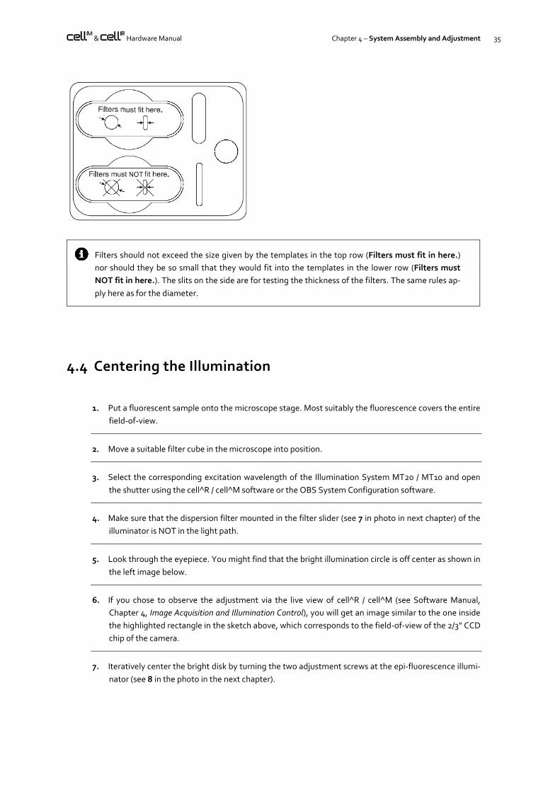
Filters should not exceed the size given by the templates in the top row (Filters must fit in here.)
nor should they be so small that they would fit into the templates in the lower row (Filters must
NOT fit in here.). The slits on the side are for testing the thickness of the filters. The same rules ap-
ply here as for the diameter.
4.4 Centering the Illumination
1. Put a fluorescent sample onto the microscope stage. Most suitably the fluorescence covers the entire
field-of-view.
2. Move a suitable filter cube in the microscope into position.
3. Select the corresponding excitation wavelength of the Illumination System MT20 / MT10 and open
the shutter using the cell^R / cell^M software or the OBS System Configuration software.
4. Make sure that the dispersion filter mounted in the filter slider (see 7 in photo in next chapter) of the
illuminator is NOT in the light path.
5. Look through the eyepiece. You might find that the bright illumination circle is off center as shown in
the left image below.
6. If you chose to observe the adjustment via the live view of cell^R / cell^M (see Software Manual,
Chapter 4, Image Acquisition and Illumination Control), you will get an image similar to the one inside
the highlighted rectangle in the sketch above, which corresponds to the field-of-view of the 2/3" CCD
chip of the camera.
7. Iteratively center the bright disk by turning the two adjustment screws at the epi-fluorescence illumi-
nator (see 8 in the photo in the next chapter).

36 Chapter 4 – System Assembly and Adjustment
4.5 Optimizing the Illuminator Tube Position
For an optimally homogeneous illumination of the specimen, it is necessary for the light cone leaving the illumi-
nator exit lens to match the position of the objective back aperture. Radial intensity gradients will result in case
the distance between exit lens and back aperture is severely off; the images are brighter in the center than at the
periphery.
Furthermore, in order to achieve maximum brightness, the exit plane of the light fiber has to be focused onto
the specimen plane. This depends on the distance between the fiber exit and the illuminator optics, in other
words, the depth of insertion of the light fiber into the illuminator. It is roughly optimized before delivery of the
system by positioning the stopper ring 3 that sets the depth of penetration of the fiber port adapter. Usually this
will be sufficient for a good illumination. However, if it is obviously defocused the light fiber position has to be re-
adjusted by slightly turning the stopper ring. To be able to do that, the setscrew 4 of the illuminator tube has to
be slightly loosened by about half a turn.
1: illuminator tube containing the optical elements
2: light guide with port adapter
3: stopper ring to adjust depth of penetration
4: set screw to fix the light guide
5: flange for IX2 microscope frame
6: screw to fix the illuminator tube inside the flange
7: filter slider with dispersion filter
8: adjustment screws for centering the illuminated field
The optical path length, which is (partly) determined by the penetration depth of the illuminator tube 1 into the
microscope frame, is likewise crucial. In this context, it is important to realize that the objective's position rela-
tive to the illuminator is changed if a piezo-electric z-drive (PIFOC) is mounted: the optical path length increases.
1
2 3
4 5
6
7
8
8

& Hardware Manual Chapter 4 – System Assembly and Adjustment 37
The penetration can easily be changed, to take a straight illuminator for IX2 microscopes as example, after
slightly loosening the fixing screw 6 in the flange 7. If the tube is either too far or not far enough inside the mi-
croscope, the overall brightness is reduced. However, the effects are hardly visible by the eye, but they can be
monitored by carefully analyzing the images.
The following table lists the optimal distances to be adjusted for the different types of illuminators. These dis-
tances are marked in the photo below. In the table you will find entries for the different microscopes that are
supported, both for the standard setup and for the cases when an objective PIFOC is installed. The objectives are
sorted in three groups.
It is inconvenient to change the illuminator position every time if objectives of all three groups are frequently
used: here, the distance of group B objectives can be chosen as a compromise.
Different illuminators, clockwise from top left: BX2, IX2 standard, IX2 L-shape, IX2 L-shape, IX2 with field stop slider. The arrows mark
the distances that have to be adjusted. The distances for illuminators mounted to the MVX microscope are the same as for the IX2
microscopes.
Optimal distance between flange and illuminator tube end [mm]
IX2 & MVX BX2
Objectives Standard Field stop L-shape BX51/61 BX51WI
A 231 79 41 139 99
B 221 69 31 129 89
C 211 59 21 119 79
A with PIFOC 215 63 25 123 99
B with PIFOC 205 53 15 113 89
C with PIFOC 195 43 5 103 79
The illumination will still be bright and homogeneous if, for example, a group C objective is used
but the illuminator is installed with the group A distance. However, for experiments that are very
critical with respect to the brightness of illumination, it might be useful to readjust the illuminator
position.

38 Chapter 4 – System Assembly and Adjustment
Groups of objectives:
A LCPLFL 20x, LCPLFL 20x PH, PLAPO 1,25x, PLAPO 2x, UPLAPO 4x, UPLFL 4x, UPLFL 20x, UPLFL 4x P,
UPLFL 20x PH, UPLFL 4x PH, UPLFL 20x PH
B CPLFL 10x PH, LCPLFL 40x, LCPLFL 40x PH, LCPLFL 60x, LCPLFL 60x PH, PLAPO 40x, PLAPO 100x O3,
PLFL 100x, SLCPLFL 40x, SLCPLFL 40x PH, UAPO 40x /340, UMPLFL 5x, UMPLFL 10x, UMPLFL 10x W,
UMPLFL 20x, UMPLFL 40x, UMPLFL 50x, UMPLFL 100x, UPLAPO 10x, UPLAPO 10x W, UPLAPO 10x PH,
UPLAPO 20x, UPLAPO 20x O, UPLAPO 20x PH, UPLAPO 40x, UPLAPO 60x, UPLFL 10x, UPLFL 10x PH,
UPLFL 10x P, UPLFL 40x, UPLFL 40x PH, UPLFL 40x PH
C all UIS2 objectives, APO100x OHR, LUMPLFL 40x W, LUMPLFL 40x W/IR, LUMPLFL 60x W, LUMPLFL 60x W/IR, PLAPO 60x O3,
PLAPO 60x O3PH, PLAPO 60X O/TIRFM-SP, UAPO 20x /340, UAPO 20x W/340, UAPO 40x W/340, UAPO 40x OI/340, UMPLFL
20x W, UPLAPO 40x OI, UPLAPO 40x OI3PH, UPLAPO 60x W, UPLAPO 100x OI, UPLAPO 100x OI3PH, UPLFL 60x OI, UPLFL 60x
OI3PH, UPLFL 100x O, UPLFL 100x OI, UPLFL 100x OP,
UPLFL 100x O3PH, XLUMPLFL20XW
The objectives highlighted bold are the most sensitive with respect to an optimal adjustment. If they are fre-
quently used, the distance should be set as corresponds to their group. If you cannot find a certain objective in
this list, please contact your local Olympus specialist.

& Hardware Manual Chapter 5 – Optional Hardware Modules 39
5 Optional Hardware Modules
A variety of additional hardware modules are available for cell^R and cell^M but do not form part of a standard
system. The following chapters may be ignored in cases where these modules are absent.
5.1 Mounting and Connecting the Piezo-Electric Objective Drive (PIFOC) ............... 41 5.2 Connecting the Piezo-Electric Nosepiece Drive (Nosepiece PIFOC for
IX2 Microscopes) ............................................................................................... 43 5.3 Connecting the Corvus Controller of a Motorized Märzhäuser Stage ................. 44 5.4 Installing Illuminators with Pinhole Field Stop Sliders ........................................ 45 5.4.1 Centering the pinhole........................................................................................ 46 5.5 Installing the OptiGrid ....................................................................................... 47 5.5.1 The OptiGrid Illuminator ................................................................................... 47 5.5.2 Connecting the OptiGrid ................................................................................... 47 5.5.3 Configuring the OptiGrid ................................................................................... 48 5.5.4 Optical Alignment of OptiGrid and Camera ....................................................... 49 5.5.5 Calibrating the OptiGrid .................................................................................... 50 5.5.6 Calibrating the OptiGrid Z-Position for Different Image Types........................... 52

40 Chapter 5 – Optional Hardware Modules
5.5.7 Stripe Filter for Snapshots ................................................................................. 54

& Hardware Manual Chapter 5 – Optional Hardware Modules 41
5.1 Mounting and Connecting the Piezo-Electric Objective Drive (PIFOC)
This optional device by Physik Instrumente GmbH, Germany, may not be part of your system.
The stage of an Olympus IX / IX2 microscope has to be lifted with the four spacer elements provided to enable the
installation of the PIFOC. The PIFOC is mounted onto the nosepiece like an objective. The electronics' housing has
to point inwards to enable free movement of the nosepiece. Due to the size of the PIFOC the neighboring objective
positions of the nosepiece are inevitably partly blocked and cannot be used.
Microscope IX81 only: In order to be able to mount the PIFOC, the black plastic cover of the nosepiece
has to be removed (3 screws, see photo above). If the cover has been modified by Olympus BioSystems
it can be reinstalled after the PIFOC is mounted. The original piece is incompatible with the mounted
PIFOC.
objective spacer
stage spacers fixing screws for the plastic
cover of the IX81 nose
piece (2 of 3 visible, the
other one is hidden on the
left side in this photo)

42 Chapter 5 – Optional Hardware Modules
1. Disconnect the socket from the piezo-drive housing.
2. Screw the socket into the nosepiece. A special "screw driver" is provided to tighten it (see the photo be-
low).
3. Place the PIFOC on top of the socket with the electronics' housing pointing inwards to enable free
movement of the nosepiece.
4. Fix the socket by turning the silver socket ring, which is accessible through the slit in the front of the
PIFOC, into direction "close" with help of the pin (see the photo below) that is likewise included.
5. The remaining free nosepiece positions can be equipped with objective spacer elements to enable parfo-
cality with the objective mounted on the PIFOC with all other objectives. Two
counter screw rings allow the fine-tuning of the objective elevation.
6. Connect the thicker black cable of the PIFOC to the port labeled SENSOR on the PIFOC controller (E-662
LVPZT-Amplifier). Your set contains an extension cord for this cable in case the length is insufficient.
7. Connect the thinner gray cable to the PIFOC controller port labeled PZT. Your set contains an extension
cord for this cable in case the length is insufficient.
8. Connect the BNC plug of the cell^R / cell^M PIFOC controller cable to the CONTROL INPUT port of the
PIFOC controller. The other end has to be plugged into the SMB port of the cell^R / cell^M controller at
the back of the PC (see Chapter 4.2.4, Connecting the Imaging PC to the Modules).
9. Configure and calibrate the PIFOC as described in the Software Manual, Chapter 15.6, Configuration of
the Pifoc.
Counter screw rings

& Hardware Manual Chapter 5 – Optional Hardware Modules 43
The two cables leaving the PIFOC restrict the possible movements of the nosepiece. Make sure that
you do not move the nosepiece too often in the same direction because eventually the cables get
wound up until no further movement is possible. Also, if you attempt to move one of the other objec-
tive positions into the optical path and the electronics' housing is not positioned carefully it may touch
the stage and block the movement.
Note for PIFOC usage via the cell^R / cell^M software:
Make sure that Servo switch on the front panel of the PIFOC controller is set to ON.
Turn the DC OFFSET knob counterclockwise as far as it will go. The PIFOC will thus be set to the 0 Mi-
crons position unless otherwise set in the software.
5.2 Connecting the Piezo-Electric Nosepiece Drive (Nosepiece PIFOC for IX2 Microscopes)
This optional device by Physik Instrumente GmbH, Germany, may not be part of your system.
1. Connect the thicker black cable of the nosepiece PIFOC to the port labeled SENSOR on the PIFOC con-
troller (E-662 LVPZT-Amplifier). Your set contains an extension cord for this cable in case the length is
insufficient.
2. Connect the thinner gray cable to the PIFOC controller port labeled PZT. Your set contains an extension
cord for this cable in case the length is insufficient.
3. Connect the BNC plug of the cell^R / cell^M PIFOC controller cable to the CONTROL INPUT port of the
PIFOC controller. The other end has to be plugged into the SMB port of the cell^R / cell^M controller at
the back of the PC (see Chapter 4.2.4, Connecting the Imaging PC to the Modules).

44 Chapter 5 – Optional Hardware Modules
4. Configure and calibrate the nosepiece PIFOC as described in the Software Manual, Chapter 15.6, Configu-
ration of the Pifoc.
5.3 Connecting the Corvus Controller of a Motorized März-häuser Stage
This optional device by Märzhäuser GmbH, Germany, may not be part of your system.
Back panel of the Corvus stage controller
In this description it is assumed that the motorized stage is mounted on the microscope frame as designed by the
manufacturer.
1. Make sure that the main switch is set to OFF.
2. Set the dipswitch 2 in the red Configuration field at the back panel of the controller to ON (up position).
All other switches have to be in OFF position (down position). This sets the Baud
rate (data transfer rate) to the correct value.
3. Connect the joystick with the male 9-pin Joystick plug.
4. Connect the female 13-pin Axis-2 plug with the y-axis motor (the one closer to the microscope frame) of
the motorized stage.
5. Connect the female 13-pin Axis-1 plug with the x-axis motor (the one closer to the edge of the stage) of
the motorized stage.

& Hardware Manual Chapter 5 – Optional Hardware Modules 45
6. Connect the male 9-pin RS-232 / Host plug with the 9-pin CTR-COM2 serial port of the cell^R Real-time
Controller / cell^M System Coordinator at the back of the imaging PC (see Chapter 4.2.4, Connecting the
Imaging PC to the Modules).
Do not use any of the PC serial ports (COM1 or PC-COM2) for the connection of the Corvus controller.
It is the cell^R Real-time Controller / cell^M System Coordinator that acts as host for the stage control-
ler, not the PC.
7. Make sure that the main switch is set to OFF and connect Mains with the power outlet.
5.4 Installing Illuminators with Pinhole Field Stop Sliders
These special illuminators contain a slider that can hold up to four inserts with a single pinhole of differing diameter
in the center. All other features are those of the standard straight and L-shape illuminators (fiber port, adjustment
screws, filter slider, photodiode etc).
The pinhole is located in the field plane and thus imaged into the focal plane to cause the exclusive illumination of a
circular region. The pinhole illumination enables the specific bleaching of a small central area of the field of view in
applications such as FRAP or FRET based on donor/acceptor bleaching.
The mounting and adjustment of the illuminators is described in Chapter 4.2.2, Mounting and Connecting the Epi-
Fluorescence Illuminator, Chapter 4.4, Centering the Illumination, and Chapter 4.5, Optimizing the Illuminator Tube
Position.
Standard pinhole sizes are 50, 100, 200 and 400 microns. The corresponding areas of illumination depend on the
magnification and are listed in the following table. Refraction and contributions of out-of-focus fluorescence may
cause the areas to be 10–20% wider in case of thick specimens

46 Chapter 5 – Optional Hardware Modules
Calculated illuminated field diameter [m]
Pinhole size [m]
Magnification 50 100 200 400
40x 2.05 4.09 8.2 16.4
60x 1.36 2.73 5.5 10.9
100x 0.82 1.64 3.3 6.6
Refraction furthermore has a strong effect on the illumination intensities. In general, it can be stated that the higher
the magnification the stronger the decrease in average intensity when using a pinhole as compared to free widefield
illumination. It should be noted that, for example in case of a 100x objective, the image of a 100-micron pinhole has
a diameter of only about three times the wavelength.
Correspondingly, a small pinhole causes a stronger loss in average illumination intensity than a larger pinhole.
Also, a low objective NA causes the drop in intensity to be especially severe. In other words, oil immersion objectives
are very much superior to air immersion objectives here.
5.4.1 Centering the pinhole
Slight variations between individual microscopes and cameras may cause the pinhole image not to be centered in
the camera field of view. The position of the pinhole can be optimized with the two screws that are accessible with a
2 mm hex wrench through two holes in the flange that houses the field stop slider.

& Hardware Manual Chapter 5 – Optional Hardware Modules 47
5.5 Installing the OptiGrid
5.5.1 The OptiGrid Illuminator
The mounting and adjustment of the illuminator is the same as described for standard illuminators in Chapter 4.2.2,
Mounting and Connecting the Epi-Fluorescence Illuminator, Chapter 4.4, Centering the Illumination, and Chapter 4.5,
Optimizing the Illuminator Tube Position.
The filter slider of the illuminator contains (in addition to the usual dispersion filter) two aperture stop pin holes of
different diameter. They serve to increase the resolution of the grid image in the focal plane, albeit at the cost of
reduced illumination intensity and the necessity of prolonged camera exposure times.
5.5.2 Connecting the OptiGrid
The OptiGrid requires a non-standard cell^M System Coordinator / cell^R Real-Time Controller with
OptiGrid TNC connector (CTR_R/OG / CTR_M/OG, respectively).
1. Connect the MOTOR plug at the back of the OptiGrid controller with the 12-pin plug on the OptiGrid
paddle using the motor cable.
3
2
2
1
1
6
4
6
3

48 Chapter 5 – Optional Hardware Modules
2. Connect the HI VOLTAGE OUTPUT plug at the back of the OptiGrid controller with the OptiGrid paddle
using the 4-pin phase control cable.
3. Connect the USB plug at the back of the OptiGrid controller with a USB port of the imaging PC using the
USB 2.0 communication cable.
4. Connect the Input BNC plug at the back of the OptiGrid controller with the OptiGrid TNC connector at
the back of the imaging PC using the BNC-to-TNC cable.
5. Insert the OptiGrid paddle the corresponding opening at the side of the microscope epi-fluorescence il-
luminator. It will slide into the outer position with a click. At this point do not move it into the inner posi-
tion.
6. Make sure that the main switch at the back of the OptiGrid controller is set to OFF and connect mains
with the power outlet.
5.5.3 Configuring the OptiGrid
Open the ObsConfig software and right-click on the icon in the top left corner to open the context menu. Select
Components to open the corresponding window. Check the option OptiGrid.
Go to the page OptiGrid and select With Z-Focus adjustment for all OptiGrids manufactured after autumn 2007.
The Position entries remain at 0 at this point. They will be changed automatically upon performing the calibration,
see below.
The Image Acquisition Properties in the Experiment Manager will contain the option Use OptiGrid. If checked
"OptiGrid" images will be acquired automatically during an experiment.

& Hardware Manual Chapter 5 – Optional Hardware Modules 49
5.5.4 Optical Alignment of OptiGrid and Camera
The optical alignment of the system is crucial for the performance of the OptiGrid. The objective pro-
jects an image of the OptiGrid into the specimen at the position of the ocular focal plane. It is impor-
tant that the focal plane of the camera coincides with this plane; in other words: camera and ocular
have to be parfocal.
The alignment has to be done with great care, otherwise the resolution enhancement using the Opti-
Grid may be negligible or artifacts may be pronounced.
Caution. Very intense and harmful light may exit the ocular if the illumination brightness is not reduced
to a high degree.
1. Start with the OptiGrid paddle mounted but resting in the outer position.
2. Start the cell^M / cell^R software, switch on the illumination system and use a filter wheel position with-
out excitation filter for illumination (see the software manual for details).
3. Move a mirror unit without excitation filter into position.
4. Set the brightness to a very low value. In case of an epi-fluorescence illuminator with standard lamp
house you have to reduce the brightness by inserting a strong neutral density filter (see the correspond-
ing manuals for details).
5. Place the OptiGrid Calibration Slide onto the microscope stage.
6. Set the microscope to ocular view (see the microscope manual).
7. Move the stage so that a border of the orange coating is visible and bring it into focus.
8. Switch the microscope to camera view and start the Live View acquisition (see the corresponding manu-
als for details). Be sure to use Binning 1x1. If necessary adjust the Exposure time in the Camera control
window.
9. If the Live View does not show a focused image, the camera position needs to be adjusted. To do so,
loosen the fixing screw at the video mount the fixes the C-mount adapter. Turn the C-
mount adapter with the camera until the image becomes focused.
As a rule of thumb, the gap between video mount and C-mount adapter has to be around 2 mm. You
may use a 2 mm Allen wrench or a 10 Euro cent coin to estimate the size of the gap.
10. Tighten the fixing screw again.
11. Move the OptiGrid slider into the inner position so that the grid becomes visible on the screen.
If necessary adjust the Exposure time in the Camera control window. It is helpful to define a Subframe

50 Chapter 5 – Optional Hardware Modules
by clicking the Define button in the Camera control window in order to get a zoomed-in view of the grid.
If necessary adjust the focus to get a nicely defined grid pattern.
12. Loosen the fixing screw in the microscope frame that fixes the video mount.
13. Turn the video mount until the grid is either vertically or horizontally aligned. The image of the
grid should look like the example below.
14. Tighten the fixing screw again.
15. Stop the Live Image acquisition and close the shutter.
The visibility of the grid pattern can be quite poor if thick samples with strong out-of-focus intensity are
imaged. The use of one of the aperture stops in the filter slider of the illuminator may improve the
situation, however, at the cost of longer exposure times and a reduced pseudo-confocal effect.
Mind that the focality and the response of the image on the slider movement strongly depend on the
depth of focus and NA of the objective used.
5.5.5 Calibrating the OptiGrid
The calibration yields meaningful results only if camera and OptiGrid are parfocal and aligned so that
the grid is oriented horizontal or vertical.
The camera may not be operated in 8bit mode for calibration.
1. Start with the OptiGrid paddle mounted but resting in the outer position.
2. Start the cell^M / cell^R software, switch on the illumination system and use a filter wheel position with-
out excitation filter for illumination (see the software manual for details).
3. Move a mirror unit without excitation filter into position.

& Hardware Manual Chapter 5 – Optional Hardware Modules 51
4. Set the brightness to a very low value. In case of an epi-fluorescence illuminator with standard lamp
house you have to reduce the brightness by inserting a strong neutral density filter (see the correspond-
ing manuals for details).
5. Place the OptiGrid Calibration Slide onto the microscope stage.
6. Switch the microscope to camera view and start the Live View acquisition (see the corresponding manu-
als for details). Be sure to use Binning 1x1. Do not yet check the option OptiGrid in the Camera control
window.
7. Move the stage so that an uncoated area of the OptiGrid Calibration Slide is visible and bring it in focus. It
is helpful to define a Subframe by clicking the Define button in the Camera control window in order to
get a zoomed-in view.
8. Move the OptiGrid paddle in. Start Live acquisition and check the Brightness adjustment: Automatic
option in the Camera control window. If necessary adjust the Exposure time so that a Max. reading of
around 3000 is reached in case of a 12-bit camera (around 50,000 in case of a 16-bit camera).
9. Check if the grid is in focus. Correct the focus if necessary.
OptiGrid settings
10. Click the OptiGrid settings button to open the corresponding window (or use AcquireOptiGrid set-
tings). Move the Grid focus position slider (or type in a number between 0 and 100) until the image be-
comes focused or stop the Live acquisition and use the Automatic button to start an autofocus routine.

52 Chapter 5 – Optional Hardware Modules
11. Select the correct stripe orientation: Horizontal stripes or Vertical stripes.
12. Use Start from old values if you are refining an earlier calibration.
13. Select Fast mode if you are using a MT10 / MT20 or similar high stability illumination system. The Fast
mode does not account for intensity fluctuations and may not give satisfying results with standard mer-
cury illumination.
14. Click Start in the OptiGrid settings window. The system will start acquiring images while moving the
grid stepwise and analyzing the movement to find the optimal step size. This process may take around
one minute; you can follow the advance in the progress bar. The Image Disturbance value shows the
improvements of the calibration. The final value is usually less than 2. If the calibration initially leads to a
higher value, just repeat the calibration.
15. Once the calibration is finished, click OK.
Check the option OptiGrid in the Camera control window and acquire a snapshot. The Viewport will show a proc-
essed image of the OptiGrid Calibration Slide with the grid stripes removed. It may look like the example below.
5.5.6 Calibrating the OptiGrid Z-Position for Different Image Types
The optimal focus position of the OptiGrid depends on the imaging wavelength and can be preset for each defined
Image Type; see the cell^M / cell^R Manual, Chapter 15.3, Definition of Image Types.
1. Mount a fluorescence-labeled specimen (or use the OptiGrid sample slide.
Move the OptiGrid paddle in.
Select the correct Image Type in the Microscope Control window.
Make sure that the OptiGrid option in the Camera Control window is NOT checked.
Start Live acquisition and focus the specimen.

& Hardware Manual Chapter 5 – Optional Hardware Modules 53
Check the Brightness adjustment: Automatic option in the Camera control window.
Be sure to use Binning 1x1.
If necessary adjust the Exposure time (or Gain) so that a Max. reading of around 3000 is reached in case
of a 12-bit camera (around 50,000 in case of a 16-bit camera).
2. Click the OptiGrid settings button to open the corresponding window (or use AcquireOptiGrid set-
tings). The current Image Type is selected in the Grid focus position: Image types box.
3. Move the Grid focus position slider (or type in a number between 0 and 100) until the stripes caused by
the OptiGrid become focused or use the Automatic button to start an autofocus routine.
4. Click Get current value. The current image type is thus connected with the current grid position.
5. Change the Image Type and repeat steps 3. and 4.
6. Once the calibration is done repeat confirm and exit with OK.
The system is now set up and the OptiGrid position will be adjusted automatically when the image type is changed.

54 Chapter 5 – Optional Hardware Modules
5.5.7 Stripe Filter for Snapshots
This function is currently available only for snapshots but not for Life images or for post-processing of
stored images.
Resulting images may show a light pattern of residual stripes even after optimal calibration of the OptiGrid. They
can be removed partly by filtering corresponding frequencies in the Fourier space.
Stripe Filter. Check this option to apply stripe filtering on snapshots to be taken when the option OptiGrid in the
Camera control window is activated.
Stripe attenuation [%]. Adjust this value empirically by taking series of snapshots with different values. 75% is a
reasonable staring point. Values close to 100% may cause new artifacts.
Bandwidth. This refers to the frequency band in the Fourier space. Adjust this value empirically by taking series of
snapshots with different values. 4 is a reasonable staring point.
Low-pass filter. Check this option to run additionally an ordinary low-pass noise filter on the resulting snapshots.

®
Printed in Germany 2009 03 M 03.2
OLYMPUS LIFE SCIENCE EUROPA GMBH Postfach 10 49 08, 20034, Hamburg, Germany
OLYMPUS AMERICA INC. 3500 Corporate Parkway, Center Valley, PA 18034, USA
OLYMPUS AUSTRALIA PTY. LTD. 31 Gilby Road, Mt. Waverley, VIC 3149, Melbourne, Australia
OLYMPUS LATIN AMERICA, INC. 6100 Blue Lagoon Drive, Suite 390 Miami, FL 33126-2087, USA
OLYMPUS SINGAPORE PTE LTD. 491B River Valley Road, #12-01/04 Valley Point Office Tower, Singapore 248373