Embed Size (px)
Citation preview

scanned by 1. G. McHone 15 Jan 2010for personal use only, not for sale
BIOLOGICAL MICROSCOPE
This instruction manual is for use of the Olympus BiologicalMicroscope Model CHD. We recommend you read thismanual carefully in order to familiarize yourself fully withthe use of your microscope so that you can obtain maximumperformance.
OLYMPUSAX!)570

BEFORE USEObserve the following procedures carefully:
a Operation------------------------__~---_-.I
CD Since the microscope is a precision instrument, always handle it with care, and avoid abrupt motions orimpacts.
(i) Avoid exposure to direct sunlight, high temperature and humidity, dust and vibration.
@ Never direct the sunlight to the microscope mirror while adjusting illumination in order to protect youreyes from the sunlight.
@ Only use the tension adjustment ring for altering the tension of the coarse adjustment knobs.
@ Be careful not to soil lens surfaces with dust, fingerprints, etc.
fJ Main18nance and .;;..Sto...;....ra _
CD Use a clean brush or lens tissue paper to clean the lens surfaces. If the lens surfaces are soiled with oil orfingerprints, wipe them off carefully with gauze moistened with a small amount of alcohol and ether(3: 7) solution, or xylene.
CV Do not use organic solutions (e.g. thinner, xylene, ether, alcohol, etc'! to wipe painted surfaces of variouscomponents, and especially, plastic parts. When extremely soiled, they shou Id be cleaned with a neutral
detergent.
@ Do not disassemble any part of microscope, since the integrated performance may be impaired.
@ When not in use, the microscope should be covered with the dust cover provided or contained in a storagecase, and kept in a place free from humidity and mold.
Attaching the fixing blocks of the microscope stand In the wooden ilqrege case ICHD-WBI(optionally avail'able,
The fixing blocks should be screwed at the bottom ofthe storage case in the following procedure:
1) Insert the screw into a flat washer and one of thetwo holes (8 mm dia.) in the base plate of the caseas illustrated at the right.
2) Tighten the screw to clamp one block by means ofthe spanner provided.
3) Clamp the other block on the opposite side.
Fixing block Storagecase
y-Flatwasher
~~

BEFORE USEObserve the following procedures carefully:
a Operation
CD Since the microscope is a precision instrument, always handle it with care, and avoid abrupt motions orimpacts.
CV Avoid exposure to direct sunlight, high temperature and humidity, dust and vibration.
@ Never direct the sunlight to the microscope mirror while adjusting illumination in order to protect youreyes from the sunlight.
@ Only use the tension adjustment ring for altering the tension of the coarse adjustment knobs.
@ Be careful not to soil lens surfaces with dust, fingerprints, etc.
II Maintenance and Stora
CD Use a clean brush or lens tissue paper to clean the lens surfaces. If the lens surfaces are soiled with oil orfingerprints, wipe them off carefully with gauze moistened with a small amount of alcohol and ether(3: 7) solution, or xylene.
CV Do not use organic solutions (e.g. thinner, xylene, ether, alcohol, etc,) to wipe painted surfaces of variouscomponents, and especially, plastic parts. When extremely soiled, they should be cleaned with a neutral
detergent.
@ Do not disassemble any part of microscope, since the integrated performance may be impaired.
@ When not in use, the microscope should be covered with the dust cover provided or contained in a storagecase, and kept in a place free from humidity and mold.
Attaching the fixing blocks of the microscope stand In the wooden storage case ICHO·\)VB)(optionally available)
The fixing blocks should be screwed at the bottom ofthe storage case in the following procedure:
1) Insert the screw into a flat washer and one of thetwo holes (8 mm dia.) in the base plate of the caseas illustrated at the right.
2) Tighten the screw to clamp one block by means ofthe spanner provided.
3) Clamp the other block on the opposite side.
Fixing block Storagecase
I y-Flatwasher
~~

CONTENTS1. STANDARD EQUIPMENT 1 I
2. SPECIFICATIONS 2 2
3. NOMENCLATURE 3 3
ASSEMBLY 4 4:4.
1 4- 1 AS$embly' DIagram 4114-~ Expranation for Assembly Pf'ocedIJre ' I
5. OBSERVATION (Putting the Microscope in Operation) 6
D Specimen Placement 6
fJ Adjustment of the Microscope Mirror 7
II Focus 7
II Interpupillary Distance Adjustment (for CH-BI45-W only) 7
II Diopter Adjustment 8
II Objective selection 8
II Adjustment of the Aperture Iris Diaphragm 8
.. Tension Adjustment of the Coarse Adjustment Knobs 9
III Locking of the Pre-focusing Lever 9
1m Use of Immersion Objectives 10
6. OPTICAL DATA 0 6
7. TROUBLE SHOOTING 11 "--_----I

I
--IZw~a..:::ldwoa::«oz~en
STANDARD EQUIPMENTCHO·
Component212E 012E OOlE
--Microscope stand with quadruple revolving nosepiece,square plain stage, including dust plug AA7808, fi Iter CHO-F 0 0 032.5C-2, immersion oil Bcc and dust cover COll
Monocular observation tube, inclined 45° CH-M045-W 0 0
Binocular observation tube, inclined 45° CH-BI45-W 0
Attachable mechanical stage with right-hand low driveCH-MVR 0 0
controls
Stage clips, paired CH-SCBI 0
Condenser, N.A. 1.25 CH2-CO 0 0 0
Filter holder CH2-FH 0 0 0
Plano-concave mirror K-MM 0 0 0
E 0 achromatic objective 4X ED4X 0
E 0 achromatic objective lOX E010X 0 0 0
E 0 achromatic objective 40X (spring) E040X/R 0 0 0
E 0 achromatic objective 100X (spring, oil) E0100X/RO 0 0
LB eyepiece lOX CWHK10X 0 0
LB eyepiece 10X(2 pcs.) CWHK10X 0
Optional accessories:
Phase contrast attachment
Simple phase contrast attachment
Vertical illuminator
Attachable mechanical stage with left-handlow drive controls
Sub-stage ilium inator
Table stand illuminator
Wooden storage case
CH2-PCO-PL
CH2-PC-PL
BH2-KMA
CH-MVL
LSK-3
LSO-W
CHO-WB
D----------------------------

2 SPECIFICATIONS
Item Description
Microscope Circular dovetail mount for observation tube; built-on quadruple nose-limb piece; and square plain stage 124 mm x 153 mm.
Coarse and fineCoaxial coarse and fine focusing controls. Coarse and fine drive range
Microscopeadjustments
25mm; fine drive knobs graduated in increments of 2.5J1.. Tension adiust-stand ment knobs, and pre-focusing lever for coarse focusing.
Condenser holder Rack and pinion condenser height displacement up to 28 mm.
BaseProvided with accommodation for attachment of microscope mirror andsubstage illuminator.
Monocular Inclined 45°.
Observation Inclined 45°. Interpupillary distance adjustment with a scale betweentubes Binocular 53mm -72 mm.
Variable diopter adjustment ring equipped on the left-side eyepiece tube.
Attachable mechanical stageLow-positioned coaxial control knobs; X-V trave~sing area 76mm x50 mm, compatible with two standard slides simultaneously.
N.A. 1.25 (in immersion oil). with graduated aperture diaphragm. Pro-Condenser vision to accept a filter holder.
Filter holder Accepts a 32.5 mm dia. filter.
Microscope mirror Plano-concave mirror (50mm dia.l
Filter Blue filter (32.5mm dia.)
ObjectivesED4X, EDlOX, ED40X (spring-loaded). ED100X (spri ng-Ioaded, oi I im-mersion)
EyepieceCWHK10X (provided with accommodation to accept an eyepiece micro-meter)
Dimensions 180 mm (W) x 223 mm (D) x 370 mm (H) (binocu lar version)
Eyepoint height Binocular: 372 mm Monocular: 375 mm
Weight CHD-212E: 4.9 kg.
--------------------------fJ
en\lm("")
."
("")
!iozen

UJa::::>I«...JuZUJ
~oz
3 NOMENCLATURE
Diopter adjustment ring
IBinocular tube
IRevolving nosepiece IIObjective I
Specimen holder
I Mirror I
Hand reset
IStage clip I
Condenser height adjustmentknob
Pre-focusing lever
IEyepiece I
Observation tubeclamping screw
Mechanical stage I
IMicroscope stand
Tension adjustment ring
Fine adjustment knob
Graduated in increments of 2.5/J.
Coarse adjustment knob
Coaxial low drive controlknobs
IMonocular tube I
Condenser clamping screw
I Condenser I
Aperture iris diaphragmlever
Filter holder
Accepts a 32.5mm dia. filter.
IJ-----------------------
4--------
ASSEMBLY
[ 4-1 Assembl,V Diagram
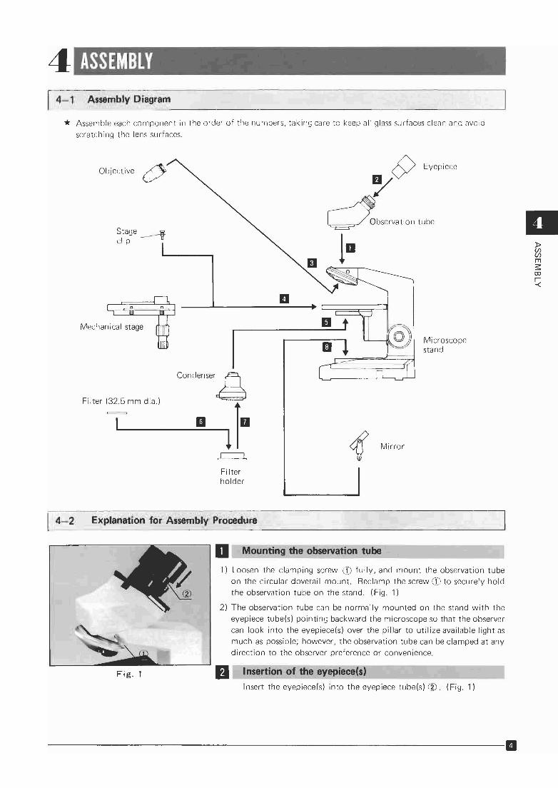
* Assemble each component in the order of the numbers, taking care to keep all glass surfaces clean and avoid
scratching the lens surfaces,
Objective ~V
Stage -------fclip
Mechanical stage
Filter (32,5 mm dia.)
condenser.g
II 101~
Filterholder
..Microscopestand
II»(f)(f)
ms:CD
~
4-2 Exp'lanation for Assembl,V Procedure
Fig. 1
D Mounting the observation tube
1) Loosen the clamping screw CD fully, and mount the observation tube
on the circular dovetail mount. Reclamp the screw CD to securely holdthe observation tube on the stand. (Fig. 1)
2) The observation tube can be normally mounted on the stand with theeyepiece tube(s) pointing backward the microscope so that the observer
can look into the eyepiece(s) over the pillar to utilize available light asmuch as possible; however, the observation tube can be clamped at any
direction to the observer preference or convenience.
IJ Insertion of the eyepiece(s)
Insert the eyepiece(s) into the eyepiece tube(s) (~). (Fig. 1)
-----------------------------11

II Fig. 2
(J)
IUse of an eyepiece micrometer IAn eyepiece micrometer (10 mm/100~ (optionally available) can be
inserted into the eyepiece CWHK10X in the following procedure:
1) Remove the retaining ring' 1./ from the lower end of the eyepieceand place the micrometer on the retaining ring with the reticleengraved surface, facing downward. (Fig. 2)
* Be certain to clean the micrometer disc before inserting into theeyepiece.
2) Return the retaining ring into the eyepiece and insert the eyepieceinto the eyepiece tube.
Fig. 3
Fig. 4
Fig. 5
III Mounting the objectives1) Lower the stage by means of the coarse adjustment knobs.
2) Screw the objectives into the nosepiece, from low power to higher
power in a clockwise direction. (Fig. 3)
* Close the empty aperture in the nosepiece with a plug CD provided.(Fig. 3)
II Mounting the mechanical stageMount the mechanical stage on the plain stage CD in a manner that
the specimen traversing guide of the mechanical stage is locatedclosest to the pillar, and tighten the stage clamping screws ® witha coin. (Fig. 4)
• Insertion of stage clips
The plain stage is pre-drilled for insertion of the stage clips when the
mechanical stage is not attached (see page 4).
II Mounting the condenserInsert the condenser into the condenser holder, with the condenser
iris diaphragm lever (1), directing in the microscope front, andtighten the clamping screw (2) . (Fig. 5)
11----------------------------

II Insertion of the blue filter
Slip the blue filter (32.5mm dia.) ® into the filter holder CD. (Fig.6)
II Insertion of the filter holder
Insert the filter holder minto the condenser from below. (Fig. 6)
5
Fig. 6
... Mounting the mirror
1) Insert the mirror C:D fork into the mirror mounting seat ® in the
base.
2) If the mirror fork is loose, pullout the mirror fork, and adjust theslit in the fork with a screwdriver.
Fig.7
oBSERVAT ION (Putting the Microscope in Operation)
oOJ(Ilm:Xl<»-I(5Z
Fig. 8
D Specimen Placement
1) Open the spring-loaded specimen finger CD, and slide the specimenslide into the holder, with the cover glass upward.Push the slide all the way against the holder and release the finger CDslowly. (Fig. 8)* A sudden release of the finger may cause damage to the slide or
the holder.
2) For use of the stage clips in place of the specimen holder, insert a pair
of stage clips into the holes on the drilled surface of the stage andinsert the specimen slide between each clip and the stage surface.
• Use of a cover glass
Use a cover glass of 0.17mm thick in conjunction with the objectives marked with the inscription "160/0.17" for optimum performance of these objectives.
• Use of a specimen slide
The thickness of a specimen slide between 0.9 mm and 1.2 mm is recommended for the CHD. If the thickness of a slide exceeds this range, illumination may sometimes be impaired.
---------------------------B

D Adjustment of the Microscope Mirror
1) Install the microscope near the window or place a lamp stand (I; in
front of the microscope. (Fig. 9)
11zoI<t:>crwCIlcoo
Fig.9
2) Looking through the observation tube, adjust the mirror angle and
direction so that the field of view is evenly illuminated. (Fig. 10)
3) The flat surface of the mirror is usually employed, unless the objective is very low power. However, if the field of view is not evenly il
luminated, use the concave surface.
4) For observation with the available light from the window or from the
fluorescent lamp in the room, remove the blue filter from the con
denser.
5) For observation with incandescent light, use the blue filter.
Fig. 10
..Fig. 11
Fig. 12
II Focus
1) Swing in the lOX objective.
2) Bring the specimen into focus by means of the focus adjustment
knobs.
* Rotate the focus adjustment knobs clockwise (in the direction of
the arrow in Fig. 11), to raise the stage (or the specimen ap
proaches to the objective), or reverse the knobs to lower the stage.
Interpupillary Distance Adjustment(for the binocular tube)
1) Looking through the binocular tube, move the knurled dovetail slides
(1, in the directions of the arrows until a perfect binocular vision isobtained. (Fig. 12)
2) If you memorize your interpupillary distance setting on the scale @
provided on the dovetail slide OJ, it is convenient to obtain a propersetting next time. (Fig. 12)
B-----------------------------

II Diopter Adjustment (for the binocular tube)
1) Look at the image through the right eyepiece with your right eye,
and focus on the specimen with the focus adjustment knobs.
2) Next, looking at the image through the left eyepiece with your lefteye, rotate the diopter adjustment ring CD to focus on the specimenwithout using the focus adjustment knobs. (Fig. 13)
Fig. 13
II Objective Selection
II1) Swing in the objective to use. (Fig. 14)
2) Be certain to click the nosepiece in position.
otoUlm::c
~~
oFig. 14 Z
II Adjustment of the Aperture Iris Diaphragm
The opening of the aperture iris diaphragm built in the condensercan be adjusted to match with the numerical aperture of theobjective in use, in order to achieve optimum objective performance such as oepth of focus, image contrast and resol ut ion.
1) Turning the diaphragm lever CD counterclockwise reduces the diaphragm opening. (Fig. 15)
Fig. 15
Exit pupilof objective
70% - 80%
30% - 20%
2) Remove the eyepiece, and looking at the exit pupil of the objectivethrough the empty eyepiece tube, adjust the opening of the diaphragm. Generally, it is preferable to stop down the aperture diaphragm to 70% to 80% of the objective N.A. (Fig. 16)If the specimen is lightly stained, or almost colorless and transparent,further reduce the diaphragm opening to increase contrast for betterobservation. Be careful, however, if the diaphragm is stopped downtoo much, the resolution will deteriorate.
Fig. 16
--------------------------11

11zof<!>a:w(f)coo
Fig. 17
Fig. 18
iii Tension Adjustment of the Coarse Adjustment Knobs
1) A tension adjustment ring CD is provided next to the coarse adjustmen t knob. Wi th this device the tension of the coarse adjustmen t isfreely adjustable for either heavy or light movement, depending upon
operator preference.Applying the blade of a large screwdriver at the knurled periphery ofthe tension adjustment ring G), rotate the ring in the direction ofthe arrow to increase the tension, or reverse the ring to loosen. (Fig.17)
2) However, do not loosen the tension adjustment ring too much, because this may cause the stage to drop or the fine adjustment knobs
to sl ip.
II Locking of the Pre-focusing Lever
The lever G) is provided to prevent possible contact between speci
men and objective as well as to simplify coarse focusing. The leveris locked, turning it in the direction of the arrow in Fig. 18, aftercoarse focus has been accomplished. This is convenient for liquidapplication or change of specimens, too, since it prevents furtherupward travel of the stage by means of the coarse adjustmentknobs, and provides a limiting stop if the stage is lowered andthen raised again. The pre-focusing lever does not restrict fine
focusing.
* Unlock this lever when not in use.
11----------------------------
1m Use of Immersion Objectives
1) To utilize the full numerical aperture of an immersion objective (with inscription "oil"). the objective andspecimen are immersed in an immersion oil in a following manner:
2) Focus on the specimen with a low power objective.
3) Put a drop of immersion oil on the specimen slide and the front lens of the immersion objective.
4) Turn the nosepiece to bring the immersion objective into the light path, and focus with the fine adjustmentknobs.
* Use of the pre·focusing lever facilitates steps 2) - 4) above.
* Care should be taken to prevent oil bubble from forming in the oil film; if any, swing the nosepiece to theright and left reciprocally several times and re-apply immersion oil, since these bubbles greatly deterioratethe lens performance.
* Be careful not to stain other objectives with immersion oil, and after use, carefully wipe off the immersionoil on the objective, etc. completely.
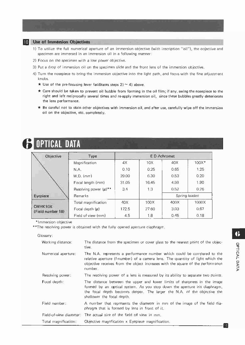
6 OPTICAL DATAObjective Type E 0 ,;A.chromat
Magnification 4X lOX 40X 100X*
N.A. 0.10 0.25 0.65 1.25
W.o. (mm) 29.00 6.30 0.53 0.20
Focal length (mm) 31.05 16.45 4.59 1.90
Resolving power (~)** 3.4 1.3 0.52 0.26
Eyepiece Remarks Spring-loaded
Total magnification 40X 100X 400X 1000XCWHK10X
Focal depth (~) 172.5 27.60 3.03 0.67(Field number 181
Field of view (mm) 4.5 1.8 0.45 0.18
*lmmersion objective**The resolving power is obtained with the fully opened aperture diaphragm.
o"'0-l(')
»ro~»
The distance from the specimen or cover glass to the nearest point of the objective.
Resolving power:
The N.A. represents a performance number which could be compared to therelative aperture (f-number) of a camera lens. The quantity of light which theobjective receives from the object increases with the square of the performancenumber.
The resolving power of a lens is measured by its ability to separate two points.
The distance between the upper and lower limits of sharpness in the imageformed by an optical system. As you stop down the aperture iris diaphragm,the focal depth becomes deeper. The larger the N.A. of the objective theshallower the focal depth.
A number that represents the diameter in mm of the image of the field diaphragm that is formed by lens in front of it.
Field-of-view diameter: The actual size of the field of view in mm.
Field number:
Focal depth:
Numerical aperture:
Glossary:
Working distance:
Total magnification: Objective magnfication x Eyepiece magnification.-------------------------------11

7 TROUBLE SHOOTING
l?Z.....aa::r:U>w-Jco::Ja0:.....
If you are unable to obtain full performance from your microscope because of your unfamiliarity with the
microscope, please consult with the table below as pointers for troubleshooting'
Trouble Clluse Remedy.- -
1. Optica'i system
a) Field of view is cut off, or Nosepiece is not clicked into place. Slightly rotate the nosepiece until itilluminated irregularly. clicks into position. (p.8)
Condenser is not correctly mounted Re-insert the condenser all the way.on the ring mount_ (p.5)
Mirror is not properly adjusted. Adjust the mirror correctly. (p.7)
Use the concave side.
b) Dust or dirt is visible in Dust or dirt on the mirror surface.the field of view. Dust on the condenser top lens.
---- Remove dust or dirt.Dirty specimen.
Dust on eyepiece.
c) Excessive image contrast. Condenser is lowered too much. Raise the condenser.
Aperture iris diaphragm is stopped Open the diaphragm. (p. 8)down too much.
d) Resolution problems: Objective is not correctly engaged in Slightly rotate the nosepiece until it• Image is not sharp. the light path. clicks into position. (p. 8)
• Insufficient contrast. Dirt on the objective front lens. Clean the objective.• Image details lack _.
definition. Immersion objective is used without Apply immersion oil. (p. 10)
immersion oil.
Bubbles in the immersion oil. Remove bubbles. (P. 10)
Olympus immersion oil is not used. Use Olympus immersion oil.
Dirty specimen.
Dust on eyepiece or condenser top lens.Clean.
e) Field of view is partially Objective is not correctly positioned in Slightly rotate the nosepiece until itout of focus. the light path. clicks into position.
Specimen is not correctly placed on Place the specimen on the stage andthe stage. secure it with the specimen holder or
stage clips.
f) Image is tinted yellowish. Incandescent light is used without Use blue filter. (p.7)blue filter.
g) Image is tinted bluish. Blue filter is used with natural light Disengage blue filter. (p.7)
or fluorescent light.
11-----------------------------

Trouble Cause Aemedy
2. Focus adjustment mechanism.-
a) Coarse adjustment knobs Tension adjustment ring is tightened Loosen the tension adjustment r in~Jare too tight. too much. slightly (p.9)
User is trying to raise the stage, passing Unlock the rre-focusing lever. (p. 9)over the upper focusing limit imposedby the engaged pre-focusing lever.
- .-b) Stage drops and the speci- Tension adjustment ring is too loose. Tighten the ring properly. (p.9)
men goes out of focus.--_.
c) Stage cannot be raised to Pre-focusing lever is engaged in lower Unlock the lever. (P. 9)the upper limit. than focusing position.
. - --_._---_._.
d) Stage cannot be lowered Substage is lowered too much. Raise the substage.
to the lower limit of theworking range.
.-
e) Objective front lens Specimen is mounted on the stage up- Reverse the specimen. (p. 6)
touches the specimen. side down.
3: Binocular tube
Incomplete binocular Interpupillary distance is not correctly Correct the interpupillary distance.vision. adjusted. (p.7)
_..- -------
Diopter adjustment is incomplete. Comp Jete the diopter acljustmen t.(p.7)
Right and left eyepieces are not Use a pair of matched eyepieces.matched.
.-
User is unaccustomed to binocular vi- Prior to looking at the image of thesion. specimen, try to look at the entire
field of view, or look at a far away
object before resuming microscopic
observation.
4. "Stage
a) Image easily goes out of Stage clamping knobs are not tight- Tighten the stage clamping screws withfocus when you touch the ened. a coil. (P. 5)stage.
-b) Image blurs as you move Specimen is not correctly positioned Place the specimen on the stage cor-
the speci men. on the stage. rectly. (p. 6)
6. QbJective change
When objectives are Specimen is mounted on the stage up- Reverse the specimen. (p. 6)changed, the fron t lens of side down.
the high power objective Cover glass is too thick. Use a 0.17 mm-thick cover glass.touches the specimen.
III-l::0oCOJrmenIoo-lZGl

scanned by J. G. McHone 15 Jan 2010for personal use only, not for sale
~_.--. _ _-OI._-..e.w.co..uo.~ ,-.' _ _ _