Embed Size (px)
Citation preview

“OLGA” &“OLGAS” SERIES
HYDRAULIC ACTUATORS FOR STANDARD PRESSURE SUPPLY

Double Acting OLGA Actuator
• General and Features pag. 1
• Cut-away Drawing and Technical Data pag. 2
• Output Torque Tables pag. 3
• Overall Dimensions pag. 4
• Manual Overrides pag. 5
Spring Return OLGAS Actuator
• General and Features pag. 8
• Cut-away Drawing and Technical Data pag. 9
• Output Torque Tables pag. 10
• Overall Dimensions pag. 15
• Manual Override pag. 17
OLGA/OLGAS Materials and Sectional Tables pag. 18
OLGA/OLGAS Configuration pag. 22
OLGA/OLGAS Sizing Criteria pag. 23
OLGA/OLGAS Control Systems pag. 27
OLGA/OLGAS Power Packs pag. 29
OLGA/OLGAS Accessories Mounting Holes pag. 30
OLGA/OLGAS Enquiry and Ordering Data pag. 31
Table of Contents
� Copyright by BIFFI Italia. All rights reserved. OLGA/S-EN-0503A !@#$ INTERNATIONAL LTD. COMPANY

OLGA Double Acting Hydraulic Actuator
Contents may change without notice � Copyright by BIFFI Italia. All rights reserved. OLGA/S-EN-0503A !@#$ INTERNATIONAL LTD. COMPANY
1
- terminals enclosures, pushbutton panels - explosionproof or intrinsically safe and/or weatherproof
- Special coatings for offshore or corrosive environments
Double acting OLGA actuator for 90° operation for On-Off and Modulating heavy duty service
GeneralThe OLGA hydraulic actuator series was engineered and is manufactured to provide maximum torque output withminimum supply pressure.Simplicity, reliability and economy are atthe top of the list of design parameters.The OLGA actuator is suitable for anyquarter turn application such as ball,plug, butterfly valves or dampers, inboth On-Off and Modulating heavyduty service.
Features- Totally enclosed, weatherproof
housing in fabricated carbon steel formaximum strength
- Canted scotch yoke actuators arethe proper solution to motorise themost common type of quarter-turnvalves, due to their dedicated torquetrend; they are suited to the largervalve sizes where high break away torques are required or for valves withhigh working pressure
- Symmetric scotch yoke actuators available for special applications
- External travel stops for precise angular stroke adjustment between82° and 98°
- Hard chromium plated and polishedguide bar and piston rod for corrosion resistance and minimal friction
- Bushings made of bronze or sintered bronze, charged withteflon, to provide minimal friction andextended service life
- Electroless nickel plated and polished cylinder for corrosion resistance and minimal friction
- Piston and piston rod seals made bya teflon ring precharged by an O-ring provide low hysteresis and highsensitivity, preventing sticking problems
- Jackscrew or hand pump manualoverride available
- An extensive range of accessoriesare available:- limit switch boxes -
explosionproof, intrinsically safe and/or weatherproof
- limit switches can be provided in different types according to customer requirements
- position transmitters - explosionproof, intrinsically safe and/or weatherproof
- oil filters
- solenoid valves - explosionproof, intrinsically safe and/or weatherproof
- control units for modulating service: - electrohydraulic “step-by-step” - electrohydraulic proportional valves complete with electronic control panel
- electrohydraulic servovalves- spool-type or poppet-type (no
leakage) control valves- dump valves, flow regulators,
relief valves- electric pressure switches- bladder-type or piston-type
accumulators according to PED directive 97/23/EC or ASMEstamped. Accumulators in accordance with different codes on request
- electrohydraulic power packs, with explosionproof and/or weatherproof protection, assembledon the actuator or separate from theactuator

1 Housing2 Yoke3 Yoke bushing4 Cover5 Guide block pin6 Sliding block7 Guide block8 Guide block bushing9 Guide bar
10 Travel stop screw11 Cylinder head flange12 Piston rod bushing13 Piston rod O-ring14 Piston rod seal ring15 Piston rod16 Piston17 Piston O-ring18 Piston seal ring19 Piston guide sliding ring20 Cylinder tube21 End flange22 Sealing washer23 Travel stop screw24 Tie rod
Item Name
1615
1413
1211
65
43
2
2423
2221
2019
1817
98
73
101
Technical dataSupplypressure : 105 bar g maximum
Supply fluid : hydraulic oil Special versions for fire-resistant fluids
Ambienttemperature : -30° C to +100° C
Special versions for service outside this range on request
Outputtorques : up to 400000 Nm
Higher values with special versions
Contents may change without notice � Copyright by BIFFI Italia. All rights reserved. OLGA/S-EN-0503
2
OLGA Double Acting Hydraulic Actuator
OLGA actuators
Oil displacementModel litres
0.3 - 75 0.70.3 - 100 1.20.9 - 100 1.40.9 - 135 2.41.5 - 135 31.5 - 175 53 - 135 53 - 175 86 - 175 106 - 200 1214 - 200 1314 - 235 1814 - 280 2618 - 235 2118 - 280 3032 - 235 2532 - 280 3550 - 235 2750 - 280 3950 - 300 45
The oil displacement is the oil volumerequired for one actuator stroke (in opening or in closing)
Note

- Max allowable pressure 105 bar g (static pressure applicable to fullystroked actuator against the travelstops)
- Angular positions: 0° Closed45° Intermediate90° Open
OLGA Double Acting Hydraulic Actuator
Contents may change without notice � Copyright by BIFFI Italia. All rights reserved. OLGA/S-EN-0503A !@#$ INTERNATIONAL LTD. COMPANY
Notes
Output Torques for Canted Yoke Mechanism
Max operating Output torque (Nm/bar g)
Model torque (Nm) at 0° at 45° at 90°
0.3C - 75 3000 64 22 310.3C - 100 3000 115 41 570.9C - 100 9000 132 47 650.9C - 135 9000 243 87 1201.5C - 135 15000 304 108 1501.5C - 175 15000 512 184 2553C - 135 30000 493 176 2443C - 175 30000 829 298 4126C - 175 60000 970 348 4826C - 200 60000 1320 451 624
14C - 200 120000 1446 515 71314C - 235 120000 1912 700 96914C - 280 120000 2715 996 137918C - 235 180000 2197 805 111418C - 280 180000 3122 1146 158632C - 235 300000 2616 955 132332C - 280 300000 3707 1360 188350C - 235 400000 2934 1073 148650C - 280 400000 4165 1528 211650C - 300 400000 4782 1739 2407
3
Output Torques for Symmetric Yoke MechanismMax
operating Output torque (Nm/bar g)Model torque (Nm) at 0° at 45° at 90°
0.3S - 75 3000 40 23 380.3S - 100 3000 73 42 690.9S - 100 9000 85 49 800.9S - 135 9000 154 89 1461.5S - 135 15000 212 113 1691.5S - 175 15000 356 191 2873S - 135 30000 346 187 2853S - 175 30000 582 316 4826S - 175 60000 679 370 5656S - 200 60000 887 479 732
14S - 200 120000 985 523 78614S - 235 120000 1360 742 111514S - 280 120000 1931 1056 158818S - 235 180000 1564 853 128318S - 280 180000 2220 1215 182732S - 235 300000 1812 1003 152932S - 280 300000 2573 1428 217750S - 235 400000 2013 1114 169950S - 280 400000 2858 1586 241950S - 300 400000 3281 1804 2751

4
A
F
D E
B
ML
K
G
C
N
Z (Hydraulic connection to open)
W (Hydraulicconnection to close)
Top view
Model A B C D E F G K L M N
OLGA Double Acting Hydraulic Actuator
Contents may change without notice � Copyright by BIFFI Italia. All rights reserved. OLGA/S-EN-0503A !@#$ INTERNATIONAL LTD. COMPANY
1.*Add C for canted yoke, S for symmetric yoke (i.e. 0.3C-135)
2. Dimensions and weights given arewith oil and without optional bracketor adaptor flange
3. For mounting flange details see separate coupling dimensions leaflet
Notes
Dimensions in mm
0.3* - 75 756 319 279 136 151 222 534 116 70 119 70 1/2 - 440.3* - 100 803 319 279 136 151 222 581 125 70 119 70 1/2 - 480.9* - 100 870 413 303 160 190 245 625 160 80 170 83 1/2 - 600.9* - 135 921 413 303 160 190 245 676 160 80 170 83 1/2 - 791.5* - 135 1011 469 343 187 227 293 718 160 100 185 100 1/2 - 1161.5* - 175 1056 469 343 187 227 293 763 196 100 185 100 1/2 - 1353* - 135 1451 586 351 285 330 391 1060 160 160 215 106 1/2 - 1903* - 175 1532 586 351 285 330 391 1141 196 160 215 106 1/2 - 2206* - 175 1625 740 414 327 379 430 1195 196 185 260 140 1/2 - 3606* - 200 1705 740 414 327 379 430 1275 230 185 260 140 - 3/4 39814* - 200 1826 873 527 376 435 496 1330 230 200 330 193 - 3/4 60014* - 235 1806 873 527 376 435 496 1310 ø 340 200 330 193 - 3/4 65014* - 280 1842 873 527 376 435 496 1346 350 200 330 193 - 3/4 70018* - 235 1972 880 511 424 492 548 1424 ø 340 230 330 196 - 3/4 80018* - 280 1953 880 511 424 492 548 1405 350 230 330 196 - 3/4 85032* - 235 2263 1055 583 505 585 643 1620 ø 340 270 395 232 - 3/4 135032* - 280 2263 1055 583 505 585 643 1620 350 270 395 232 - 3/4 138050* - 235 2460 1092 584 548 633 700 1760 ø 340 300 387 233 - 3/4 150050* - 280 2460 1092 584 548 633 700 1760 350 300 387 233 - 3/4 154050* - 300 2500 1092 584 548 633 700 1800 392 300 387 233 - 3/4 1580
Hydraulic Hydraulicconnection connection WeightNPT (X-Y) NPT (W-Z) (Kg)
Y (Hydraulic connection to open)
X (Hydraulicconnection to close)
Overall dimensions

OLGA Double Acting Hydraulic Actuator
Contents may change without notice � Copyright by BIFFI Italia. All rights reserved. OLGA/S-EN-0503A !@#$ INTERNATIONAL LTD. COMPANY
5
Local manual controlThe OLGA actuators can only have thehydraulic manual override for the operation. The compact hydraulic control unitmounted on the actuator consists of :- hand pump- directional control valve to select the
“to open” or “to close” actuator operation
- relief valve to prevent the oil pressuredelivered by the hand pump fromexceeding the maximum allowablevalue
- oil tankAccessories are available on request, forinstance:- dual pilot operated check valve- bladder-type or piston-type
accumulator
Emergency manual overrideThe OLGA actuators can have an emergency manual override in addition to the local and/or remote control panel which controls the oil supplied by a power pack for the “normal” actuator operation.The emergency manual override, mounted on the actuator, consists of ahydraulic manual override and a hydraulic manual selector to chooseactuator “Normal operation” with oilsupply from a power pack, or the“Emergency manual operation”.The compact hydraulic manual overrideconsists of:- hand pump- directional control valve to select the
“to open” or “to close” operation byhand pump
- relief valve to prevent the oil pressuredelivered by the hand pump fromexceeding the maximum allowablevalue
On request the emergency manual override can be included in the powerpack.
1 2
D
P R
O
1 2
3
4
D
P R
O
Hydraulicconnections to the hydraulic control panel (to close)(to open)
1. Scotch yoke mechanism2. Hydraulic cylinder3. Hydraulic manual overrideD=Directional control valveP= Hand pumpR= Relief valveO=Oil tank
1. Scotch yoke mechanism2. Hydraulic cylinder3. Hydraulic manual override4. Hydraulic manual selectorD=Directional control valveP=Hand pumpR=Relief valveO=Oil tank
3

OLGA Double Acting Hydraulic Actuator
Contents may change without notice � Copyright by BIFFI Italia. All rights reserved. OLGA/S-EN-0503A !@#$ INTERNATIONAL LTD. COMPANY
6
A
F G ED
R
N
C
Manual override lever (removable)
Jackscrew Hydraulicturns connection Weight
per stroke NPT (Kg)
Dimensions in mm
0.3* - 75-MSJ 1021 319 279 136 151 487 534 116 70 119 70 437 30 1/2 550.3* - 100-MSJ 1068 319 279 136 151 487 581 125 70 119 70 437 30 1/2 590.9* - 100-MSJ 1136 413 303 160 190 511 625 125 80 170 83 437 35 1/2 710.9* - 135-MSJ 1187 413 303 160 190 511 676 160 80 170 83 437 35 1/2 901.5* - 135-MSJ 1314 469 343 187 227 596 718 160 100 185 100 627 35 1/2 1301.5* - 175-MSJ 1359 469 343 187 227 596 763 196 100 185 100 627 35 1/2 1493* - 135-MSJ� 1977 586 351 285 330 917 1060 160 160 215 106 627 56 1/2 2073* - 175-MSJ� 2058 586 351 285 330 917 1141 196 160 215 106 627 56 1/2 237
1.*Add C for canted yoke, S for symmetric yoke (i.e. 0.3C-75-MSJ)
2.� Max operating torque with jackscrewmanual override is 19000 Nm
3. Dimensions and weights given arewith oil and without optional bracketor adaptor flange
Notes
K
M
LB
Manual override type ”MSJ”
The MSJ jackscrew manual override canbe supplied for OLGA and OLGA-H actuators up to model 3. The override is mounted on the left sideof the actuator, the jackscrew end isscrewed into the guide block. A bronzesplit screw nut is mounted inside thebody. By rotating the engagement lever,the screw nut is engaged with thejackscrew.When the screw nut is engaged with the jackscrew manual operation follows byrotating the body of the screw containerby a lever.
Hydraulic connection to close
top view
Model A B C D E F G K L M N R
Hydraulic connection to open
OLGA Double Acting Hydraulic Actuator
Contents may change without notice � Copyright by BIFFI Italia. All rights reserved. OLGA/S-EN-0503A !@#$ INTERNATIONAL LTD. COMPANY
7
ENGAGEDENGAGED TO OPENTO OPEN
DISENGAGEDDISENGAGED TO CLOSETO CLOSE
1 3 4 5 6 7 8 9 10 11 12 13 14
15 16 17 18 19 20 21 22 23 24 25 26 27 28
� Recommended spare parts
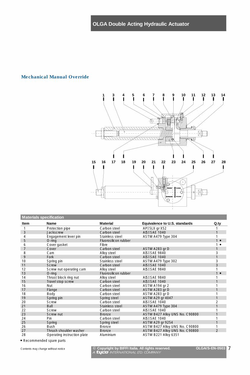
Mechanical Manual Override
Materials specification
Item Name Material Equivalence to U.S. standards Q.ty1 Protection pipe Carbon steel API 5LX gr X52 13 Jackscrew Carbon steel AISI SAE 1040 14 Engagement lever pin Stainless steel ASTM A479 Type 304 15 O-ring Fluorosilicon rubber 1 �6 Cover gasket Fibre 1 �7 Cover Carbon steel ASTM A283 gr D 18 Cam Alloy steel AISI SAE 9840 39 Fork Carbon steel AISI SAE 1040 1
10 Spring pin Stainless steel ASTM A479 Type 302 311 Screw Carbon steel AISI SAE 1040 312 Screw nut operating cam Alloy steel AISI SAE 9840 113 O-ring Fluorosilicon rubber 1 �14 Thrust block ring nut Alloy steel AISI SAE 9840 115 Travel stop screw Carbon steel AISI SAE 1040 116 Nut Carbon steel ASTM A194 gr 2 117 Flange Carbon steel ASTM A283 gr D 118 Body Carbon steel ASTM A283 gr D 119 Spring pin Spring steel ASTM A29 gr 4047 120 Screw Carbon steel AISI SAE 1040 221 Ball Stainless steel ASTM A479 Type 304 122 Screw Carbon steel AISI SAE 1040 123 Screw nut Bronze ASTM B427 Alloy UNS No. C90800 124 Pin Carbon steel AISI SAE 1040 125 Spring Spring steel ASTM A29 gr 9254 126 Bush Bronze ASTM B427 Alloy UNS No. C90800 127 Thrush shoulder washer Bronze ASTM B427 Alloy UNS No. C90800 228 Operating instruction plate Aluminium ASTM B221 Alloy 6351

8
Spring return OLGAS actuator for 90° operation for On-Off and Modulating heavy duty service
GeneralThe OLGAS hydraulic spring returnactuator series was engineered and ismanufactured to provide fail safe operation for any quarter turn application such as ball, plug, butterflyvalves or dampers, in both On-Off andModulating heavy duty service. Simplicity, reliability and economy are at the top of the list of design parameters. The spring module incorporates up tofour springs, fully encapsulated in a factory-welded cartridge. This ensuressafety to personnel and ease of assembly.
Features- Totally enclosed, weatherproof
housing in fabricated carbon steel formaximum strength
- Canted scotch yoke actuators arethe proper solution to motorise themost common type of quarter-turnvalves, due to their dedicated torquetrend; they are suited to the largervalve sizes where high break away torques are required or for valves withhigh working pressure
- Symmetric scotch yoke actuatorsavailable for special applications
- External travel stops for precise angular stroke adjustment between82° and 98°
- Hard chromium plated and polishedguide bar and piston rod for corrosion resistance and minimal friction
- Bushings made of bronze or sintered bronze, charged withteflon, to provide minimal friction andextended service life
- Electroless nickel plated and polished cylinder for corrosion resistance and minimal friction
- Piston and piston rod seals made bya teflon ring precharged by an O-ring provide low hysteresis and highsensitivity of actuator, preventingsticking problems
- Hand pump manual override available- Spring module to provide fail-safe
operation- The spring return pack incorporates
up to four springs, fully encapsulated in a factory welded cartridge: this ensures safety to personnel and simplifies assembly
- The spring action can be easily changed in the field from to close into open or viceversa (modular design)
- An extensive range of accessoriesare available:- limit switch boxes explosionproof,
intrinsically safe and/or weatherproof;limit switches can be provided in different types according to customer requirements
- position transmittersexplosionproof, intrinsically safe and/or weatherproof
- oil filters- solenoid valves - explosionproof,
intrinsically safe and/or weatherproof;- control units for modulating service:
- electrohydraulic “step-by-step” - electrohydraulic proportional valves complete with electronic control panel
- electrohydraulic servovalves- spool-type or poppet-type (no
leakage) control valves- dump valves, flow regulators,
relief valves
- electric pressure switches- bladder-type or piston-type
accumulators ISPESL and TÜVstamped. Accumulators in accordance with different codes on request
- electrohydraulic power packs, withexplosionproof and/or weatherproof protection, assembled on the actuator or separate from the actuator
- terminals enclosures, pushbutton panels - explosionproof or intrinsically safe and/or weatherproof
- Special coatings for offshore or corrosive environments
- Special versions with built-in dump valves and dumper for“quick spring operation”
OLGAS Spring Return Hydraulic Actuator
Contents may change without notice � Copyright by BIFFI Italia. All rights reserved. OLGA/S-EN-0503A !@#$ INTERNATIONAL LTD. COMPANY

OLGAS Spring Return Hydraulic Actuator
Contents may change without notice � Copyright by BIFFI Italia. All rights reserved. OLGA/S-EN-0503A !@#$ INTERNATIONAL LTD. COMPANY
1 Housing2 Yoke3 Yoke bushing4 Cover5 Guide block pin6 Sliding block7 Guide block8 Guide bar9 Guide block bushing
10 Travel stop screw11 Cylinder head flange12 Piston rod bushing13 Piston rod O-ring14 Piston rod seal ring15 Piston rod16 Piston17 Piston O-ring18 Piston seal ring19 Piston guide sliding ring20 Cylinder tube21 End flange22 Sealing washer23 Travel stop screw24 Tie rod25 Spring container26 Spring27 Container rod28 Container rod bushing29 Spring thrust flange30 Guide rod31 Guide rod bushing
Item Name
9
16
242322
21201918
179 8
7 31
2625
10
1514
1312
65 4 3
227
2829
3031
11
Technical dataSupplypressure : 105 bar g maximum
Supply fluid : hydraulic oil Special versions for fire-resistant fluids
Ambienttemperature : -30° C to +100°C
Special versions for service outside this range on request
Spring ending torques : from 390 up to
80000 NmHigher values with special versions
OLGAS actuators
Oil displacementModel litres
0.3-0150-100 1.20.3-0150-75 0.70.9-0200-135 2.40.9-0200-100 1.40.9-0350-135 2.40.9-0350-100 1.40.9-0400-135 2.40.9-0400-100 1.40.9-0700-135 2.40.9-0700-100 1.41.5-1100-175 51.5-1100-135 31.5-1200-175 51.5-1200-135 33-2000-175 83-2000-135 56-2500-200 126-2500-175 106-3800-200 126-3800-175 1014-5400-280 2614-5400-235 1814-5400-200 1314-8300-280 2614-8300-235 1814-8300-200 1318-9600-280 3018-9600-235 2118-9800-280 3018-9800-235 21
The oil displacement is the oil volumerequired for one actuator stroke (in opening or in closing)
Note

OLGAS Spring Return Hydraulic Actuator
� Copyright by BIFFI Italia. All rights reserved. OLGA/S-EN-0503A !@#$ INTERNATIONAL LTD. COMPANY
Operating supply pressure (bar g)30 40 50 60 70 80
OST ORT OET OST ORT OET OST ORT OET OST ORT OET OST ORT OET OST ORT OET
0.3-0150-100-CL 78 43 74 146 40 460.3-0150-75-CL 80 44 740.9-0200-135-CL 100 56 97 376 125 1620.9-0200-100-CL 103 57 98 157 37 380.9-0350-135-CL 198 109 185 278 63 650.9-0350-100-CL 202 110 1870.9-0400-135-CL 267 134 2190.9-0400-100-CL 270 135 2210.9-0700-135-CL 355 186 3100.9-0700-100-CL 359 187 3121.5-1100-175-CL 522 321 5731.5-1100-135-CL 527 323 5751.5-1200-175-CL 714 391 6641.5-1200-135-CL 720 393 6663-2000-175-CL 1130 589 9773-2000-135-CL 1140 592 9816-2500-200-CL 1700 853 13906-2500-175-CL 1700 854 13906-3800-200-CL 2540 1190 18806-3800-175-CL 2550 1190 188014-5400-280-CL 3670 1800 293014-5400-235-CL 3680 1800 293014-5400-200-CL 3680 1810 293014-8300-280-CL 4800 2330 377014-8300-235-CL 4810 2330 377014-8300-200-CL 4810 2330 377018-9600-280-CL 6460 3570 610018-9600-235-CL 6480 3580 611018-9800-280-CL 7990 4490 773018-9800-235-CL 8010 4500 7750
249 86 112111 26 26 177 52 63 243 78 100623 221 301292 91 115 427 145 191 563 198 267 698 251 344525 163 204
329 85 94 465 139 170 600 193 246456 136 165 695 233 304
396 112 131 532 166 208 667 219 284368 65 65 615 174 205
443 104 108 579 160 1841020 237 245
700 64 64 1010 233 240828 140 140
820 135 135 1130 286 3111410 341 360 2280 691 849
1400 335 352 1910 546 644 2430 751 9352200 586 659 3530 1110 1400 4850 1630 2150
2290 620 707 3300 1020 1270 4320 1420 18502690 738 849 4010 1260 1590
2460 647 722 3480 1050 1290 4490 1450 18604750 1300 1500 7590 2490 3100 9990 3550 4700
4240 1090 1210 6240 1900 2330 8240 2680 34604940 1370 1600 6390 1950 2420 7830 2520 3230
6470 1840 2160 9310 2960 3760 5120 1290 1400 7120 2090 2530 9120 2890 3650
3810 669 669 5260 1350 1480 6710 1930 23009770 2320 2440 13040 3660 4280
9560 2230 2320 11870 3190 362011510 2500 2500 14780 3880 4340
10340 1840 1840
Spring Torque 20Model SET SRT SST OST ORT OET
Output Torques for Spring to Close Canted Yoke Mechanism (in daNm)
Notes
- Max allowable pressure 105 bar g(static pressure applicable to fullystroked actuator against the travelstop)
- Angular positions: 0° Closed45° Intermediate90° Open
- SET: Spring Ending Torque to close (0°)SRT: Spring Running Torque (45°)SST: Spring Starting Torque to close (90°)OST: Oil Starting Torque to open (0°)ORT: Oil Running Torque (45°)OET: Oil Ending Torque to open (90°)
10 Contents may change without notice

OLGAS Spring Return Hydraulic Actuator
Contents may change without notice � Copyright by BIFFI Italia. All rights reserved. OLGA/S-EN-0503A !@#$ INTERNATIONAL LTD. COMPANY
Notes
Operating supply pressure (bar g)30 40 50 60 70 80
OET ORT OST OET ORT OST OET ORT OST OET ORT OST OET ORT OST OET ORT OST
0.3-0150-100-OP 136 36 40 82 44 750.3-0150-75-OP 138 37 410.9-0200-135-OP 172 43 47 316 133 2020.9-0200-100-OP 176 45 49 72 46 830.9-0350-135-OP 331 86 95 121 81 1480.9-0350-100-OP 334 87 960.9-0400-135-OP 393 111 1290.9-0400-100-OP 396 112 1310.9-0700-135-OP 556 150 1710.9-0700-100-OP 559 152 1731.5-1100-175-OP 1010 232 2391.5-1100-135-OP 1010 234 2421.5-1200-175-OP 1170 305 3371.5-1200-135-OP 1180 307 3403-2000-175-OP 1730 473 5413-2000-135-OP 1740 476 5456-2500-200-OP 2470 695 8106-2500-175-OP 2480 696 8126-3800-200-OP 3370 1010 12306-3800-175-OP 3370 1010 123014-5400-280-OP 5210 1490 176014-5400-235-OP 5220 1490 176014-5400-200-OP 5220 1490 176014-8300-280-OP 6700 1930 229014-8300-235-OP 6700 1930 230014-8300-200-OP 6700 1930 230018-9600-280-OP 10660 2690 294018-9600-235-OP 10680 2700 295018-9800-280-OP 13510 3360 363018-9800-235-OP 13530 3370 3640
212 91 13943 30 56 116 57 92 189 83 128 262 109 163
590 230 336223 100 157 373 154 230 523 207 303 673 260 377395 180 282 669 277 415
178 102 176 328 156 249 479 209 322 629 263 396319 152 244 593 250 378
102 74 139 253 129 212 403 182 285 553 236 359 699 289 432120 99 195 393 200 329 667 298 462
203 130 226 353 185 309 504 239 303 469 302 547 1050 513 831
460 299 543 807 425 712 1150 550 881262 223 443 844 438 727
254 220 439 600 349 608 946 474 777699 429 762 1660 777 1230 2490 1146 1798
685 423 755 1250 632 1030 1830 836 1310 2400 1040 1590 1290 705 1190 2760 1230 1910 4230 1750 2630
1390 740 1240 2510 1140 1790 3640 1540 2340 4760 1940 28901660 874 1450 3130 1400 2170 4610 1920 2890
1410 783 1330 2540 1180 1880 3670 1580 2430 4790 1980 29802930 1540 2570 6090 2660 4110 9240 3780 5650
2370 1330 2290 4590 2130 3370 6810 2920 4460 9030 3700 55401530 1020 1880 3140 1610 2670 4750 2190 3450 6360 2760 4240
4260 2140 3510 7420 3260 5050 1110 980 1970 2770 1600 2780 4990 2400 3860 7210 3190 4940 9430 3980 6030
1320 1060 2070 2930 1650 2850 4540 2240 36404910 3010 5350 8530 4320 7120 12160 5620 8890
2120 1960 3990 4680 2920 5240 7320 3850 6480 5040 3410 6290 8660 4740 8060 12990 6050 9830
3740 2920 5660
Spring Torque 20Model SST SRT SET OET ORT OST
Output Torques for Spring to Open Canted Yoke Mechanism (in daNm)
- Max allowable pressure 105 bar g(static pressure applicable to fullystroked actuator against the travelstop)
- Angular positions: 0° Closed45° Intermediate90° Open
- SST: Spring Starting Torque to open (0°)SRT: Spring Running Torque (45°)SET: Spring Ending Torque to open (90°)OET: Oil Ending Torque to close (0°)ORT: Oil Running Torque (45°)OST: Oil Starting Torque to close (90°)
11

OLGAS Spring Return Hydraulic Actuator
Contents may change without notice � Copyright by BIFFI Italia. All rights reserved. OLGA/S-EN-0503A !@#$ INTERNATIONAL LTD. COMPANY
Operating supply pressure (bar g)30 40 50 60 70 80
OST ORT OET OST ORT OET OST ORT OET OST ORT OET OST ORT OET OST ORT OET
0.3S-0150-100-CL 54 42 91 87 42 550.3S-0150-75-CL 56 43 920.9S-0200-135-CL 69 55 120 230 129 2030.9S-0200-100-CL 71 56 122 93 40 450.9S-0350-135-CL 137 106 229 164 69 750.9S-0350-100-CL 139 108 2310.9S-0400-135-CL 180 132 2070.9S-0400-100-CL 183 133 2720.9S-0700-135-CL 243 182 3830.9S-0700-100-CL 245 184 3851.5S-1100-175-CL 368 304 6241.5S-1100-135-CL 372 306 6271.5S-1200-175-CL 500 375 7241.5S-1200-135-CL 504 377 7273S-2000-175-CL 792 570 10903S-2000-135-CL 798 573 10906S-2500-200-CL 1180 830 15606S-2500-175-CL 1180 831 15606S-3800-200-CL 1760 1170 21106S-3800-175-CL 1760 1170 212014S-5400-280-CL 2550 1750 320014S-5400-235-CL 2570 1760 321014S-5400-200-CL 2570 1760 321014S-8300-280-CL 3340 2270 412014S-8300-235-CL 3350 2270 413014S-8300-200-CL 3350 2280 413018S-9600-280-CL 4550 3440 668018S-9600-235-CL 4560 3450 669018S-9800-280-CL 5610 4300 844018S-9800-235-CL 5630 4310 8450
161 90 139 234 136 223 65 28 30 107 55 77 148 81 125 189 108 172 231 134 219
385 228 380 540 326 557 178 96 142 263 150 240 348 204 337 433 285 434 518 312 531 603 366 629319 171 252 474 270 429 629 368 607
196 91 112 281 146 209 366 201 306 451 255 404 536 309 501276 143 203 431 242 380 586 341 558
153 62 63 238 119 160 323 173 257 408 228 354 493 282 452369 184 249 524 284 426 679 383 604
262 114 126 347 169 223 432 225 320687 265 293 1040 481 638
681 261 288 894 391 493 1110 519 698556 171 171 913 404 515
550 165 165 763 313 370 976 442 576 1190 568 781933 377 430 1520 733 1010 2100 1080 1590
925 371 421 1270 585 766 1620 794 1110 1970 1000 14601460 635 785 2350 1170 1670 3240 1710 2560 4130 2240 3450 4990 2770 4330
1510 670 843 2200 1080 1520 2880 1490 2200 3560 1900 2880 4240 2300 35601780 795 1010 2670 1330 1900 3560 1870 2780 4450 2400 3670
1630 702 860 2310 1120 1540 2990 1530 2220 3670 1930 29003200 1400 1770 5140 2550 3640 7070 3690 5500 9010 4830 7370
2860 1200 1440 4230 2010 2760 5590 2820 4070 6950 3620 5390 8310 4420 6700 2350 879 946 3340 1480 1900 4320 2070 2850 5310 2660 3800
4370 1970 2560 6300 3120 4420 8240 4260 6290 9990 5390 81603450 1420 1670 4820 2240 2990 6180 3050 4300 7540 3850 5620
3550 1480 1770 4540 2070 27206540 2560 2890 8770 3920 5040 10990 5240 7190 13210 6560 9330
4830 1240 1240 6400 2480 2750 7970 3440 42707720 2840 3000 9940 4220 5150 12170 5560 7300
6920 2230 2230
Spring Torque 20Model SET SRT SST OST ORT OET
Output Torques for Spring to Close Symmetric Yoke Mechanism (in daNm)
Notes
- Max allowable pressure 105 bar g(static pressure applicable to fullystroked actuator against the travelstop)
- Angular positions: 0° Closed45° Intermediate90° Open
- SET: Spring Ending Torque to close (0°)SRT: Spring Running Torque (45°)SST: Spring Starting Torque to close (90°)OST: Oil Starting Torque to open (0°)ORT: Oil Running Torque (45°)OET: Oil Ending Torque to open (90°)
12

OLGAS Spring Return Hydraulic Actuator
Contents may change without notice � Copyright by BIFFI Italia. All rights reserved. OLGA/S-EN-0503A !@#$ INTERNATIONAL LTD. COMPANY
Operating supply pressure (bar g)30 40 50 60 70 80
OET ORT OST OET ORT OST OET ORT OST OET ORT OST OET ORT OST OET ORT OST
0.3S-0150-100-OP 82 39 49 57 44 930.3S-0150-75-OP 83 39 500.9S-0200-135-OP 103 47 57 207 134 2480.9S-0200-100-OP 105 49 59 53 45 1040.9S-0350-135-OP 198 92 114 89 78 1850.9S-0350-100-OP 200 94 1160.9S-0400-135-OP 237 118 1590.9S-0400-100-OP 239 119 1610.9S-0700-135-OP 334 161 2080.9S-0700-100-OP 336 162 2111.5S-1100-175-OP 681 261 2881.5S-1100-135-OP 684 263 2911.5S-1200-175-OP 796 333 4021.5S-1200-135-OP 799 335 4053S-2000-175-OP 1150 511 6463S-2000-135-OP 1160 515 6526S-2500-200-OP 1640 747 9686S-2500-175-OP 1640 748 9706S-3800-200-OP 2240 1070 14706S-3800-175-OP 2240 1080 147014S-5400-280-OP 3520 1600 208014S-5400-235-OP 3530 1600 209014S-5400-200-OP 3540 1600 209014S-8300-280-OP 4530 2070 271014S-8300-235-OP 4540 2070 272014S-8300-200-OP 4540 2070 272018S-9600-280-OP 7160 2940 348018S-9600-235-OP 7170 2950 349018S-9800-280-OP 9090 3700 433018S-9800-235-OP 9100 3710 4340
139 91 170 222 138 247 32 29 71 79 56 114 125 83 157 172 109 200 218 136 243
381 233 409 555 331 570 148 100 193 243 154 281 339 209 370 434 263 458 529 317 546 625 371 635263 179 346 437 278 508 611 377 66930 30 130 125 100 219 221 155 307 316 209 396 411 264 484 507 318 572
215 151 302 389 251 463 562 349 62477 71 174 173 127 262 268 182 351 363 236 439 459 290 528
95 94 246 269 197 407 442 297 56853 53 206 148 127 295 243 183 383 339 238 472
333 285 596 733 499 910 1130 710 1190327 282 591 565 410 778 803 536 965 1040 661 1150
190 190 482 591 423 795 991 634 1110423 333 663 661 460 850 899 586 1040
495 409 805 1150 762 1380 1800 1110 1900 2460 1460 2430485 403 842 875 615 1160 1260 823 1470 1650 1030 1780
908 681 1340 1910 1220 2150 2900 1750 2950 3900 2280 3760 4900 2800 4570972 716 1390 1740 1130 2010 2500 1530 2630 3260 1940 3240 4030 2340 3860
1170 848 1630 2160 1380 2440 3160 1910 3250 4160 2440 4050 4990 2970 4860996 756 1500 1760 1170 2110 2520 1570 2730 3290 1980 3350
2050 1480 2810 4220 2630 4500 6390 3760 6200 8560 4890 79001670 1280 2510 3200 2090 3700 4720 2890 4900 6250 3690 6090 7780 4480 7300
1090 966 2060 2200 1560 2920 3310 2150 3790 4410 2730 4660808 808 2140 2980 2080 3840 5150 3210 5530 7310 4350 7230 9480 5480 8930
1950 1530 3040 3480 2340 4230 5010 3140 5430 6540 3940 6620956 956 2260 2060 1590 3120 3170 2180 3990
3500 2870 5850 5990 4210 7810 8480 5520 9760 10980 6820 117101580 1580 4350 3340 2780 5730 5090 3730 71103590 3200 6860 6090 4560 8810 8580 5880 10760
2700 2690 6160
Spring Torque 20Model SST SRT SET OET ORT OST
Output Torques for Spring to Open Symmetric Yoke Mechanism (in daNm)
Notes
- Max allowable pressure 105 bar g(static pressure applicable to fullystroked actuator against the travelstop)
- Angular positions: 0° Closed45° Intermediate90° Open
- SST: Spring Starting Torque to open (0°)SRT: Spring Running Torque (45°)SET: Spring Ending Torque to open (90°)OET: Oil Ending Torque to close (0°)ORT: Oil Running Torque (45°)OST: Oil Starting Torque to close (90°)
13
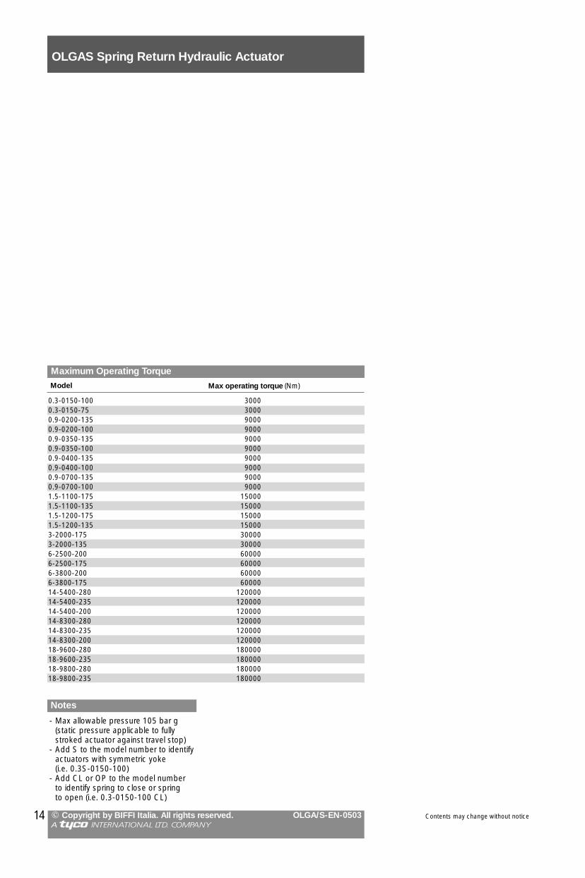
- Max allowable pressure 105 bar g (static pressure applicable to fullystroked actuator against travel stop)
- Add S to the model number to identifyactuators with symmetric yoke (i.e. 0.3S-0150-100)
- Add CL or OP to the model number to identify spring to close or spring to open (i.e. 0.3-0150-100 CL)
Notes
Maximum Operating Torque
0.3-0150-100 30000.3-0150-75 30000.9-0200-135 90000.9-0200-100 90000.9-0350-135 90000.9-0350-100 90000.9-0400-135 90000.9-0400-100 90000.9-0700-135 90000.9-0700-100 90001.5-1100-175 150001.5-1100-135 150001.5-1200-175 150001.5-1200-135 150003-2000-175 300003-2000-135 300006-2500-200 600006-2500-175 600006-3800-200 600006-3800-175 6000014-5400-280 12000014-5400-235 12000014-5400-200 12000014-8300-280 12000014-8300-235 12000014-8300-200 12000018-9600-280 18000018-9600-235 18000018-9800-280 18000018-9800-235 180000
Model Max operating torque (Nm)
Contents may change without notice
OLGAS Spring Return Hydraulic Actuator
� Copyright by BIFFI Italia. All rights reserved. OLGA/S-EN-0503A !@#$ INTERNATIONAL LTD. COMPANY
14

15
Dimensions in mm
0.3-0150-100-CL 1346 319 314 136 151 765 581 210 125 70 119 70 35 279 1/2 - 840.3-0150-75-CL 1299 319 314 136 151 765 534 210 116 70 119 70 35 279 1/2 - 800.9-0200-135-CL 1533 413 353 160 190 857 676 265 160 80 170 83 50 303 1/2 - 1660.9-0200-100-CL 1482 413 353 160 190 857 625 265 125 80 170 83 50 303 1/2 - 1470.9-0350-135-CL 1586 413 383 160 190 910 676 325 160 80 170 83 80 303 1/2 - 2000.9-0350-100-CL 1535 413 383 160 190 910 625 325 125 80 170 83 80 303 1/2 - 1810.9-0400-135-CL 1520 413 383 160 190 844 676 325 160 80 170 83 80 303 1/2 - 1950.9-0400-100-CL 1469 413 383 160 190 844 625 325 125 80 170 83 80 303 1/2 - 1760.9-0700-135-CL 1547 413 383 160 190 871 676 325 160 80 170 83 80 303 1/2 - 2170.9-0700-100-CL 1496 413 383 160 190 871 625 325 125 80 170 83 80 303 1/2 - 1981.5-1100-175-CL 1726 493 451 187 227 963 763 415 196 100 185 100 108 343 1/2 - 3681.5-1100-135-CL 1681 493 451 187 227 963 718 415 160 100 185 100 108 343 1/2 - 3491.5-1200-175-CL 1825 473 431 187 227 1062 763 375 196 100 185 100 88 343 1/2 - 3411.5-1200-135-CL 1780 473 431 187 227 1062 718 375 160 100 185 100 88 343 1/2 - 3223-2000-175-CL 2721 586 453 285 330 1580 1141 415 196 160 215 106 102 351 1/2 - 6463-2000-135-CL 2640 586 453 285 330 1580 1060 415 160 160 215 106 102 351 1/2 - 6176-2500-200-CL 3181 740 466 327 379 1906 1275 383 230 185 260 140 52 414 - 3/4 8846-2500-175-CL 3101 740 466 327 379 1906 1195 383 196 185 260 140 52 414 1/2 - 8316-3800-200-CL 3413 740 547 327 379 2138 1275 545 230 185 260 140 133 414 - 3/4 13976-3800-175-CL 3333 740 547 327 379 2138 1195 545 196 185 260 140 133 414 1/2 - 134414-5400-280-CL 3386 838 698 376 435 2040 1346 545 360 200 295 193 150 548 - 3/4 211014-5400-235-CL 3350 838 698 376 435 2040 1310 545 Ø340 200 295 193 150 548 - 3/4 206014-5400-200-CL 3370 838 698 376 435 2040 1330 545 230 200 295 193 150 548 - 3/4 200014-8300-280-CL 3460 838 698 376 435 2114 1346 545 360 200 295 193 150 548 - 3/4 216014-8300-235-CL 3424 838 698 376 435 2114 1310 545 Ø340 200 295 193 150 548 - 3/4 211014-8300-200-CL 3444 838 698 376 435 2114 1330 545 230 200 295 193 150 548 - 3/4 205018-9600-280-CL 4092 940 749 427 495 2687 1405 580 360 230 340 196 184 565 - 3/4 265018-9600-235-CL 4111 940 749 427 495 2687 1424 580 Ø340 230 340 196 184 565 - 3/4 261018-9800-280-CL 4092 940 749 427 495 2687 1405 580 360 230 340 196 184 565 - 3/4 300018-9800-235-CL 4111 940 749 427 495 2687 1424 580 Ø340 230 340 196 184 565 - 3/4 2960
Model A B C D E F G ØH K L M N P Q
Hydraulicconnection
NPT WeightX Y (Kg)
OLGAS Spring Return Hydraulic Actuator
Contents may change without notice � Copyright by BIFFI Italia. All rights reserved. OLGA/S-EN-0503A !@#$ INTERNATIONAL LTD. COMPANY
1. Dimensions and weights given arewith oil and without optional bracketor adaptor flange
2. For mounting flange details see separate coupling dimensions leaflet
Notes
Air breather
Hydraulicconnection X
D E
M LB
K
Hydraulicconnection Y
Mounting Bracket(optional)
Only for models 14 and 18
CQ
P N
AGF
ØH
3. Add S to the model number to identify actuators with symmetricyoke (i.e. 0.3S-0150-100 CL )
4. The air breather in the head flangehas the same NPT size of thehydraulic connection
top view
Air breather
Overall dimensions for spring to close actuators

Dimensions in mm
0.3-0150-100-OP 1346 319 314 136 151 566 780 210 125 70 119 70 35 279 1/2 - 840.3-0150-75-OP 1299 319 314 136 151 519 780 210 116 70 119 70 35 279 1/2 - 800.9-0200-135-OP 1533 413 353 160 190 646 887 265 160 80 170 83 50 303 1/2 - 1660.9-0200-100-OP 1482 413 353 160 190 595 887 265 125 80 170 83 50 303 1/2 - 1470.9-0350-135-OP 1586 413 383 160 190 646 940 325 160 80 170 83 80 303 1/2 - 2000.9-0350-100-OP 1535 413 383 160 190 595 940 325 125 80 170 83 80 303 1/2 - 1810.9-0400-135-OP 1520 413 383 160 190 646 874 325 160 80 170 83 80 303 1/2 - 1950.9-0400-100-OP 1469 413 383 160 190 595 874 325 125 80 170 83 80 303 1/2 - 1760.9-0700-135-OP 1547 413 383 160 190 646 901 325 160 80 170 83 80 303 1/2 - 2170.9-0700-100-OP 1496 413 383 160 190 595 901 325 125 80 170 83 80 303 1/2 - 1981.5-1100-175-OP 1726 493 451 187 227 723 1003 415 196 100 185 100 108 343 1/2 - 3681.5-1100-135-OP 1681 493 451 187 227 678 1003 415 160 100 185 100 108 343 1/2 - 3491.5-1200-175-OP 1825 473 431 187 227 723 1102 375 196 100 185 100 88 343 1/2 - 3411.5-1200-135-OP 1780 473 431 187 227 678 1102 375 160 100 185 100 88 343 1/2 - 3223-2000-175-OP 2721 586 453 285 330 1096 1625 415 196 160 215 106 102 351 1/2 - 6463-2000-135-OP 2640 586 453 285 330 1015 1625 415 160 160 215 106 102 351 1/2 - 6176-2500-200-OP 3181 740 466 327 379 1223 1958 383 230 185 260 140 52 414 - 3/4 8846-2500-175-OP 3101 740 466 327 379 1143 1958 383 196 185 260 140 52 414 1/2 - 8316-3800-200-OP 3413 740 547 327 379 1223 2190 545 230 185 260 140 133 414 - 3/4 13976-3800-175-OP 3333 740 547 327 379 1143 2190 545 196 185 260 140 133 414 1/2 - 134414-5400-280-OP 3387 838 698 376 435 1288 2099 545 360 200 295 193 150 548 - 3/4 211014-5400-235-OP 3351 838 698 376 435 1252 2099 545 Ø340 200 295 193 150 548 - 3/4 206014-5400-200-OP 3371 838 698 376 435 1272 2099 545 230 200 295 193 150 548 - 3/4 200014-8300-280-OP 3461 838 698 376 435 1288 2173 545 360 200 295 193 150 548 - 3/4 216014-8300-235-OP 3425 838 698 376 435 1252 2173 545 Ø340 200 295 193 150 548 - 3/4 211014-8300-200-OP 3445 838 698 376 435 1272 2173 545 230 200 295 193 150 548 - 3/4 205018-9600-280-OP 4092 940 749 427 495 1337 2755 580 360 230 340 196 184 565 - 3/4 265018-9600-235-OP 4111 940 749 427 495 1356 2755 580 Ø340 230 340 196 184 565 - 3/4 261018-9800-280-OP 4092 940 749 427 495 1337 2755 580 360 230 340 196 184 565 - 3/4 300018-9800-235-OP 4111 940 749 427 495 1356 2755 580 Ø340 230 340 196 184 565 - 3/4 2960
Model A B C D E F G ØH K L M N P Q
Hydraulicconnection
NPT WeightX Y (Kg)
OLGAS Spring Return Hydraulic Actuator
Contents may change without notice � Copyright by BIFFI Italia. All rights reserved. OLGA/S-EN-0503A !@#$ INTERNATIONAL LTD. COMPANY
1. Dimensions and weights given arewith oil and without optional bracketor adaptor flange
2. For mounting flange details see separate coupling dimensions leaflet
Notes
Air breather
Hydraulicconnection X
D E
M L B
K
Hydraulicconnection Y
Air breather
Mounting Bracket(optional)
Only for models 14 and 18
C Q
PN
AGF
ØH
3. Add S to the model number to identify actuators with symmetricyoke (i.e. 0.3S-0150-100 OP)
4. The air breather in the head flangehas the same NPT size of thehydraulic connection
top view
16
Overall dimensions for spring to open actuators

Contents may change without notice � Copyright by BIFFI Italia. All rights reserved. OLGA/S-EN-0503A !@#$ INTERNATIONAL LTD. COMPANY
OLGAS Spring Return Hydraulic Actuator
Emergency manual overrideThe OLGAS actuators can have anemergency manual override in additionto the local and/or remote control panel which controls the oil supplied by a power pack for the “normal” actuator operation.The emergency manual override mounted on the actuator, consists of ahydraulic manual override and a hydraulic manual selector to choose theactuator “Normal operation”, with oilsupply from a power pack, or the“Emergency manual operation”.The compact hydraulic manual overrideconsists of:- hand pump to deliver oil from the tank
to the actuator cylinder to control theactuator operation against the spring
- stop valve which allows the connection of the actuator cylinder tothe oil tank to control the actuatoroperation by spring
- relief valve to prevent the oil pressuredelivered by the hand pump fromexceeding the maximum allowablevalue
- oil tank.On request the emergency manual override can be included in the powerpack.
1 23
4
5
S
C
PR
O
Hydraulicconnection
to the hydraulic control panel
17
1. Scotch yoke mechanism2. Hydraulic cylinder3. Spring cartridge4. Hydraulic manual override5. Hydraulic manual selectorS=Stop valveC=Check valveP=Hand pumpR=Relief valveO=Oil tank

18
OLGA/OLGAS Materials and Sectional Tables
Contents may change without notice � Copyright by BIFFI Italia. All rights reserved. OLGA/S-EN-0503A !@#$ INTERNATIONAL LTD. COMPANY
Materials specification
Item Name Material Equivalence to U.S. standards
1 Housing Carbon steel ASTM A537 cl.1 +ASTM A283 gr D2 Yoke Carbon steel API 5LX gr X52 (C<0.2%) +ASTM A537 cl.13 Yoke bushing Bronze ASTM B427 Alloy UNS No. C908004 Cover Carbon steel ASTM A283 gr D5 Guide block pin Alloy steel AISI SAE 98406 Sliding block Bronze ASTM B427 Alloy UNS No C908007 Guide block Carbon steel ASTM A537 cl.18 Guide bar Alloy steel (Chromium plated) AISl SAE 98409 Guide block bushing Steel +Bronze +Teflon
10 Travel stop screw Carbon steel AISI SAE 104011 Cylinder head flange Carbon steel ASTM A283 gr D12 Piston rod bushing Steel +Bronze +Teflon13 Piston rod O-ring Nitrile rubber14 Piston rod seal ring Teflon15 Piston rod Alloy steel (Chromium plated) AISI SAE 984016 Piston Carbon steel ASTM A283 gr D17 Piston O-ring Nitrile rubber18 Piston seal ring Teflon19 Piston guide sliding ring Teflon +Graphite20 Cylinder tube Carbon steel (Nickel plated) API 5LX gr X5221 End flange Carbon steel ASTM A283 gr D22 Sealing washer PVC23 Travel stop screw Carbon steel AISI SAE 104024 Tie rod Alloy steel AISI SAE 984025 Spring container Carbon steel ASTM A283 gr D + ASTM A106 gr B26 Spring Carbon steel ASTM A29 gr 925427 Container rod Alloy steel (Chromium plated) AISI SAE 984028 Container rod bushing Steel +Bronze +Teflon29 Spring thrust flange Carbon steel ASTM A283 gr D30 Guide rod Alloy steel (Chromium plated) AISI SAE 984031 Guide rod bushing Steel +Bronze +Teflon
16
242322
21201918
179 8
7 31
2625
10
1514
1312
65 4 3
227
2829
3031
11
1615
1413
1211
65
43
2
2423
2221
2019
1817
98
73
101

15
OLGA/OLGAS Materials and Sectional Tables
Contents may change without notice � Copyright by BIFFI Italia. All rights reserved. OLGA/S-EN-0503A !@#$ INTERNATIONAL LTD. COMPANY
19
1 2 1 3 4 5 6 7 8 9 10 11 12 1314 16
A
B
A
B
Materials specificationItem Name Material Equivalence to U.S. standards Q.ty
1 O-ring NBR 4 �2 Yoke bushing Bronze ASTM B427 Alloy UNS No. C90800 23 Retainer ring Stainless steel ASTM A479 Type 302 24 Housing Carbon steel ASTM A537 cl1+ASTM A283 gr D 15 Guide bar Alloy steel AISI SAE 9840 (chromium plated) 16 Yoke Carbon steel API 5LX gr X52 (C<0.2%)+ASTM A537 cl 1 17 Cover gasket Fibre 1 �8 Guide block Carbon steel ASTM A537 cl 1 19 Bushing Steel+Bronze+Teflon 1
10 Sliding block Bronze ASTM B427 Alloy UNS No. C90800 211 Vent valve Stainless steel ASTM A479 Type 304 1 �12 Screw Carbon steel AISI SAE 1040 1613 Cover Carbon steel ASTM A283 gr D 114 Guide block pin Alloy steel AISI SAE 9840 115 Washer Copper 116 Inspection plug Carbon steel AISI SAE 1040 1
Scotch Yoke Mechanism
� Recommended spare parts

Hydraulic cylinder for OLGA/OLGAS actuators
15
Materials specificationItem Name Material Equivalence to U.S. standards Q.ty
1 Piston rod bushing Steel + Bronze + Teflon 12 Head flange Carbon steel ASTM A105 13 O-ring NBR 2 �4 Piston rod seal ring Teflon + graphite 1 �5 O-ring NBR 1 �6 Piston rod Alloy steel (chromium plated) AISI SAE 9840 17 Piston Carbon steel ASTM A105 18 Guide sliding ring for piston Teflon + graphite 1 �9 Piston seal ring Teflon + graphite 1 �
10 Tie rod Alloy steel AISI SAE 9840 411 Travel stop screw Carbon steel AISI SAE 1040 112 Cylinder tube Carbon steel (nickel plated) API 5LX gr X52 113 End flange Carbon steel ASTM A105 114 Nut Carbon steel ASTM A194 gr 2 115 Spring washer Carbon steel AISI SAE 9840 416 Nut Carbon steel ASTM A194 gr 2 417 Sealing washer PVC 1 �18 Plug Carbon steel AISI SAE 1040 2
19 O-ring NBR 1 �
1 2
3
4
5
6
7
8 919
10
11
12
14 1617 18
A
B
� Recommended spare parts
13
20
OLGA/OLGAS Materials and Sectional Tables
Contents may change without notice � Copyright by BIFFI Italia. All rights reserved. OLGA/S-EN-0503A !@#$ INTERNATIONAL LTD. COMPANY

21
Spring cartridge for OLGAS actuator
OLGA/OLGAS Materials and Sectional Tables
� Copyright by BIFFI Italia. All rights reserved. OLGA/S-EN-0503A !@#$ INTERNATIONAL LTD. COMPANY
Materials specificationItem Name Material Equivalence to U.S. standards Q.ty
1 Nut Carbon steel ASTM A194 gr 2 12 Washer Carbon steel AISI SAE 1040 13 Sealing washer PVC 1 �4 Travel stop screw Carbon steel AISI SAE 1040 15 Spring container Carbon steel ASTM A283 gr D + ASTM A106 gr B 16 Spring Carbon steel ASTM A29 gr 9254 17 Nut Carbon steel ASTM A194 gr 2 18 Shoulder washer Carbon steel AISI SAE 1040 19 Guide rod bushing Steel + Bronze + Teflon 1
10 Guide rod Alloy steel (chromium plated) AISI SAE 9840 111 Spring thrust flange Carbon steel ASTM A283 gr D 112 Container rod bushing Steel + Bronze + Teflon 113 Container rod Alloy steel (chromium plated) AISI SAE 9840 1
1 2 3 4 5 6 7 8 9 10 11 12 13
� Recommended spare parts
Contents may change without notice

OLGA/OLGAS Configuration
Contents may change without notice � Copyright by BIFFI Italia. All rights reserved. OLGA/S-EN-0503A !@#$ INTERNATIONAL LTD. COMPANY
22
Item Name
1 Scotch yoke mechanism2 Hydraulic cylinder3 Spring cartridger4 Travel stop screw5 Manual override type “MSJ”6 Local position indicator7 Electric limit switch box
1
3 3
4
5
6
7
22
Main configuration assembly

OLGA/OLGAS Sizing Criteria
Safety factorIt is essential to confirm if the above torque values include a safety factor.Depending on the valve applicationadditional safety factors may have to beconsidered over and above thoserecommended.
Maximum allowable stem torqueMaximum torque the valve stem canwithstand.
Valve stem dimensions
Operating conditions datarequired� Supply medium pressure range
(minimum, normal, maximum)� Type of actuator: double acting or
spring return to close or spring returnto open
� On-Off or Modulating service� Frequency of operation and required
operating times
Actuator sizing generalcriteriaA safety factor must be included duringsizing if not included in the figures supplied by the valve manufacturer. The safety factor value has to be defined as a function of the valve typeand size, of the working condition andof the operating time. The safety factoris usually included in the range from 1.2to 1.5: higher values have to beemployed in the case of extremeworking conditions (for instance in caseof low temperature, dirty and/or highviscosity medium, very infrequent operation, modulating service, shortoperating time).The output torques values listed in theperformance tables of actuators do notinclude a safety factor but are the minimum guaranteed torques.
23Contents may change without notice � Copyright by BIFFI Italia. All rights reserved. OLGA/S-EN-0503A !@#$ INTERNATIONAL LTD. COMPANY
Valve data requiredBreak to open torqueRequired torque to move the valve awayfrom its closed position under the fulldifferential pressure. This torque valuemust take into account the possiblesticking effect which could affect thevalve if it is closed for a long time.
Reseating torqueRequired torque to close the valve underthe full differential pressure.
Break to close torqueRequired torque to move the valve awayfrom its open position with maximumworking pressure in the pipeline. Thistorque value can be high in the case of“double block and bleed” ball valves.
End to open torqueRequired torque to fully open the valve.
Running torqueRequired torque to actuate the valve inopening and in closing without differential pressure along the angularstroke except the fully open and fullyclosed positions where the required torques are those listed above.
Dynamic torqueRequired torque to actuate the valve inopening under the medium flow throughthe valve. This torque value is high particularly on modulating service andwhen the medium speed and specificgravity are high.The angular position where the dynamictorque occurs has to be defined.

OLGA/OLGAS Sizing Criteria
� Copyright by BIFFI Italia. All rights reserved. OLGA/S-EN-0503A !@#$ INTERNATIONAL LTD. COMPANY
24 Contents may change without notice
Sizing of OLGAdouble acting actuators
OLGA actuators come in two versions,the standard one with canted scotchyoke mechanism and as a special withsymmetric scotch yoke mechanism.
Sizing of OLGA actuators with cantedscotch yoke mechanism
Canted scotch yoke mechanism is utilised as a standard since its outputtorque characteristic is in general moresuited to overcome the required valvetorque throughout the 90° stroke.For actuator sizing the followingcomparisons between the valve data,including safety factors, and the actuator data have to be performed.� Check that the actuator output torque
to open at 0° (closed valve position),with minimum supply pressure,exceeds the valve “break to open torque” with maximum differential pressure
� Check that the actuator output torqueto close at 90° (open valve position),with minimum supply pressure,exceeds the valve “break to close torque” with maximum working pressure in the pipeline
� Check that the actuator output torqueat 45° (intermediate position), withminimum supply pressure, exceedsthe valve “running torque”
� Where a valve “dynamic torque” ispresent, check that this torque value isoverridden by the actuator output torque at 45° (intermediate position),with minimum supply pressure.For a more accurate sizing BIFFIshould be consulted
� Check that the valve stem dimensionsare within the accepted values of theactuator selected size, unless anadaptor is required for other dimensional reasons
� During operation the actuator provides, along its full travel, only atorque equal to the required valve torque. No problems will occur if theactuator output torque, as listed in theperformance table, exceeds the valvemaximum allowable stem torque. But if there is the possibility that thevalve stops along its stroke, due toabnormal conditions, it is necessary tocheck that the actuator output torque,with the maximum supply pressure,does not exceed the valve maximumallowable stem torque and the actuator maximum operating torque
Sizing of OLGAactuators with symmetricscotch yoke mechanism
Symmetric scotch yoke mechanism isavailable on request as a special. The torque output characteristicsgenerated are more suited to applications where:
� the valve “break to close torque” ishigher than the 50% of “break to opentorque”: this happens for example inthe case of “double block and bleed”ball valves
� the valve “running torque” is higherthan the 40% of “break to open torque” while utilising the canted yoke mechanism the actuator outputtorque is higher than the valve and/oractuator maximum allowable torquee.g. in the case of abnormal functioning or when the specificationsrequire to consider this occurrence.
The checks that have to be performedfor actuator sizing are the same as forcanted scotch yoke mechanism.
OLGA (double acting)canted yoke mechanism
0°Closed
90°Open
45°Angular Position
Torq
ue
OLGA (double acting) symmetric yoke mechanism
models 1,5 and larger
Torq
ue
models 0,3-0,9
0°Closed
90°Open
45°Angular Position

Contents may change without notice
OLGA/OLGAS Sizing Criteria
� Copyright by BIFFI Italia. All rights reserved. OLGA/S-EN-0503A !@#$ INTERNATIONAL LTD. COMPANY
25
Sizing of OLGAS singleacting actuatorsOLGAS single acting spring returnactuators can be supplied as spring toclose (OLGAS-CL) or spring to open(OLGAS-OP).
Sizing of OLGAS-CLspring to close actuatorswith canted scotch yokemechanism
The canted scotch yoke mechanism isutilised as a standard as the output torque characteristics, of both oil andspring operation, are in general moresuited to overcome the required valvetorque throughout the 90° stroke. For actuator sizing the following comparisons between the valve data,including safety factors, and the actuator data have to be performed.� Check that the “spring ending torque”
of actuator exceeds the valve “reseating torque” with maximum differential pressure
� Check that the “oil starting torque” ofactuator, with minimum supply pressure, exceeds the valve “break toopen torque” with maximum differential pressure
� Check that the “spring starting torque” of actuator exceeds the valve“break to close torque” with maximumworking pressure in the pipeline
� Check that the “oil ending torque” ofactuator, with minimum supply pressure, exceeds the valve “end toopen torque”
� Check that both the “spring runningtorque” and the “oil running torque”,with minimum supply pressure, of theactuator exceed the valve “runningtorque”
� Where a valve “dynamic torque” ispresent, check that it is overridden bythe actuator “oil running torque”, withminimum supply pressure. For a more accurate sizing BIFFIshould be consulted
� Check that the valve stem dimensionsare within the accepted values of theactuator selected size, unless anadaptor is required for other dimensional reasons
� When required, since there is the possibility that the valve stops duringits stroke due to abnormal conditions,it is necessary to check that theactuator “spring output torque” andthe “oil output torque”, with maximumsupply pressure, do not exceed thevalve maximum allowable stem torqueand the actuator maximum operatingtorque
OLGAS-CL (spring to close) canted yoke mechanism
0°Closed
90°Open
Torq
ue
OIL STROKE
SPRING STROKE
45°Angular Position

Sizing of OLGAS-OP spring to open actuators with canted scotch yokemechanism
The canted scotch yoke mechanism is utilised as a standard as the output torque characteristics, of both oil andspring operation, are in general more suited to overcome the required valvetorque throughout the 90° stroke. For actuator sizing the following comparisons between the valve data, including safety factors, and the actuator data have to be performed.� Check that the “oil ending torque” of
actuator, with minimum supply pressure, exceeds the valve “reseatingtorque”, with maximum differentialpressure
� Check that the “spring starting torque”of actuator exceeds the valve “breakto open torque” with maximum differential pressure
� Check that the “oil starting torque” ofactuator, with minimum supply pressure, exceeds the valve “break toclose torque” with maximum workingpressure in the pipeline
� Check that the “spring ending torque”of actuator exceeds the valve “end toopen torque”
� Check that both the “spring runningtorque” and the “oil running torque”,with minimum supply pressure,exceed the valve “running torque”
� Where a valve “dynamic torque” ispresent, check that it is overridden bythe actuator “spring running torque”.For a more accurate sizing BIFFIshould be consulted
� Check that the valve stem dimensionsare within the accepted values ofactuator selected size, unless anadaptor is required for other dimensional reason
� When required, since there is the pos-sibility that the valve stops during itsstroke due to abnormal conditions, itis necessary to check that the actuator “spring output torque” andthe “oil output torque”, with maximumsupply pressure, do not exceed thevalve maximum allowable stem torqueand the actuator maximum operatingtorque
Sizing of OLGAS-OP spring to open actuators with symmetric scotch yoke mechanism
The symmetric scotch yoke mechanismis a special version that can be utilisedwhen more suited to the required valvetorque throughout the 90° stroke. E.g. the valve “break to close torque” ishigher than the “reseating torque”. The checks that have to be performedfor actuator sizing are the same as forcanted yoke mechanism.
OLGAS-OP (spring to open) symmetric yoke mechanism
OIL STROKE
SPRING STROKE
0°Closed
90°Open
Torq
ue
OLGAS-OP (spring to open) canted yoke mechanism
OIL STROKE
SPRING STROKE
0°Closed
90°Open
Torq
ue
45°Angular Position
45°Angular Position
Sizing of OLGAS-CLspring to close actuatorswith symmetric scotchyoke mechanism
The symmetric scotch yoke mechanismis a special version that can be utilisedwhen more suited to the required valvetorque throughout the 90° stroke. E.g.when the valve “break to close torque”is higher than the “reseating torque”.The checks that have to be performedfor actuator sizing are the same as forcanted scotch yoke mechanism.
OIL STROKE
SPRING STROKE
OLGAS-CL (spring to close) symmetric yoke mechanism
0°Closed
90°Open
Torq
ue
45°Angular Position
OLGA/OLGAS Sizing Criteria
� Copyright by BIFFI Italia. All rights reserved. OLGA/S-EN-0503A !@#$ INTERNATIONAL LTD. COMPANY
26 Contents may change without notice
27
OLGA/OLGAS Control Systems
Contents may change without notice � Copyright by BIFFI Italia. All rights reserved. OLGA/S-EN-0503A !@#$ INTERNATIONAL LTD. COMPANY
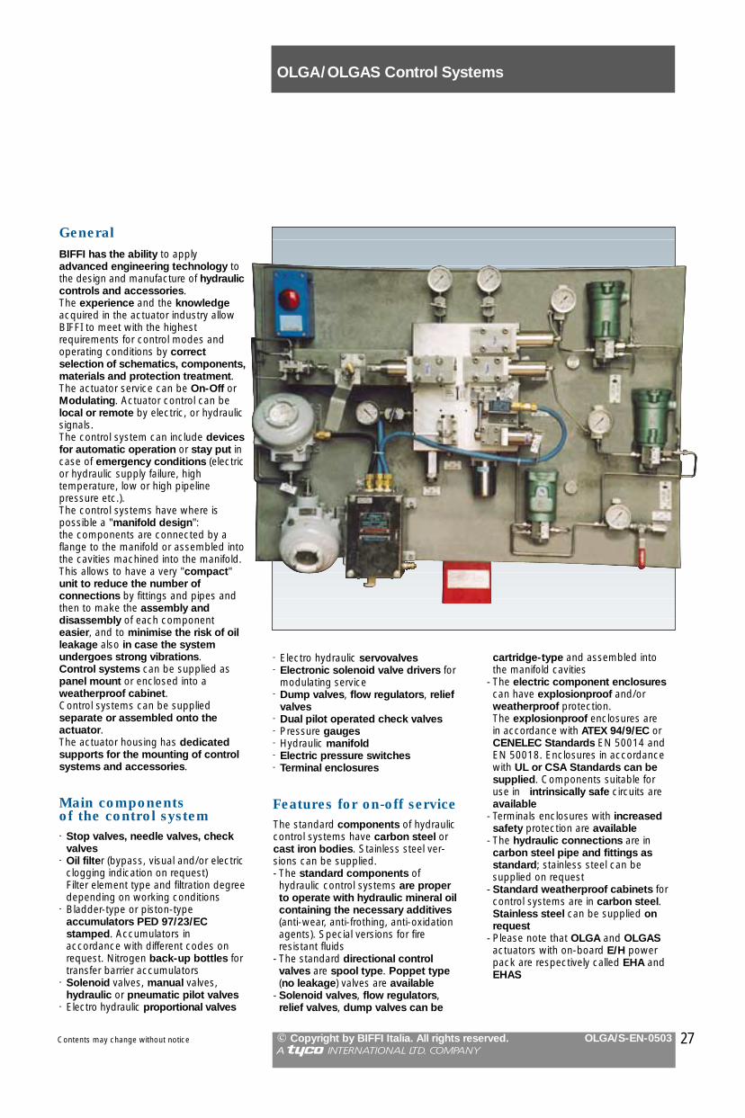
GeneralBIFFI has the ability to apply advanced engineering technology tothe design and manufacture of hydrauliccontrols and accessories. The experience and the knowledgeacquired in the actuator industry allowBIFFI to meet with the highest requirements for control modes andoperating conditions by correctselection of schematics, components,materials and protection treatment. The actuator service can be On-Off orModulating. Actuator control can belocal or remote by electric, or hydraulicsignals.The control system can include devicesfor automatic operation or stay put incase of emergency conditions (electricor hydraulic supply failure, high temperature, low or high pipeline pressure etc.). The control systems have where is possible a "manifold design": the components are connected by aflange to the manifold or assembled intothe cavities machined into the manifold.This allows to have a very "compact"unit to reduce the number of connections by fittings and pipes andthen to make the assembly and disassembly of each componenteasier, and to minimise the risk of oilleakage also in case the systemundergoes strong vibrations.Control systems can be supplied aspanel mount or enclosed into aweatherproof cabinet.Control systems can be supplied separate or assembled onto the actuator.The actuator housing has dedicatedsupports for the mounting of controlsystems and accessories.
Main components of the control system- Stop valves, needle valves, check
valves- Oil filter (bypass, visual and/or electric
clogging indication on request) Filter element type and filtration degreedepending on working conditions
- Bladder-type or piston-type accumulators PED 97/23/EC stamped. Accumulators in accordance with different codes onrequest. Nitrogen back-up bottles fortransfer barrier accumulators
- Solenoid valves, manual valves,hydraulic or pneumatic pilot valves
- Electro hydraulic proportional valves
- Electro hydraulic servovalves- Electronic solenoid valve drivers for
modulating service- Dump valves, flow regulators, relief
valves- Dual pilot operated check valves- Pressure gauges- Hydraulic manifold- Electric pressure switches- Terminal enclosures
Features for on-off serviceThe standard components of hydrauliccontrol systems have carbon steel orcast iron bodies. Stainless steel ver-sions can be supplied.- The standard components of hydraulic control systems are properto operate with hydraulic mineral oil containing the necessary additives(anti-wear, anti-frothing, anti-oxidationagents). Special versions for fire resistant fluids
- The standard directional control valves are spool type. Poppet type(no leakage) valves are available
- Solenoid valves, flow regulators,relief valves, dump valves can be
cartridge-type and assembled intothe manifold cavities
- The electric component enclosurescan have explosionproof and/orweatherproof protection. The explosionproof enclosures are in accordance with ATEX 94/9/EC orCENELEC Standards EN 50014 andEN 50018. Enclosures in accordancewith UL or CSA Standards can besupplied. Components suitable foruse in intrinsically safe circuits areavailable
- Terminals enclosures with increasedsafety protection are available
- The hydraulic connections are in carbon steel pipe and fittings as standard; stainless steel can be supplied on request
- Standard weatherproof cabinets forcontrol systems are in carbon steel.Stainless steel can be supplied onrequest
- Please note that OLGA and OLGASactuators with on-board E/H powerpack are respectively called EHA andEHAS

28
Features for modulating serviceA very important application for hydraulic actuators is modulating service. This is a frequent application inpower plants, platforms, on ships,docks, chemical plants and, more generally, in industrial plants on steam,water, oil and gas lines, where it isnecessary to regulate the flow of a fluidinside a pipe. Modulating actuators arealso often used for quick emergencyoperation: closing (stop valve) or opening (vent valve, by-pass valve). This application is especially frequent onadduction lines for steam or gas to theturbine and for water to the condenser,where it is necessary for the valve tooperate in a very short time in case ofemergency.The experience and knowledge Biffiacquired in the field of modulatingactuators satisfy the Customers' strictest specifications and the severestworking conditions through suitable calculation procedures, a correct selection of functional schematics, components, materials and protectiontreatments.The hydraulic actuators utilized formodulating service can either be doubleacting (OLGA and OLGA/H) or springreturn (OLGAS and OLGAS/H). Springreturn actuators are generally utilizedwhen quick emergency operation isnecessary.
Control systems classificationThe hydraulic control systems used formodulating actuators can be classifiedaccording to three basic types:Step by step: the hydraulic unit controlling the actuator movement consists in poppet-type solenoid valvesmounted in a manifold. The actuator hastwo operation speed possibilities: "highspeed" when the error is high, "lowspeed" when the error is small. This avoids all hunting problems. Both"high" and "low" speed are adjustableby way of flow regulators in the manifold.An electronic control panel, especially designed by BIFFI, compares the valveposition signal with the reference signalcoming from the process regulator and,according to the the position error, operates the relevant solenoid valves for actuation and speed selection. The "step-by-step" control system isgenerally used in case the modulating
(low and/or high ambient temperature, vibrations, aggressive atmosphere,peculiar electric supply with specialvalues and variation range). For this reason high-performance andspecial construction electronic components are utilized, which areassembled in accordance with procedures ensuring perfect functioningin the severest working conditions onfield.The use of microprocessors and digitaltechniques for positioning units allowsto supply the positioner/actuatorassembly with the possibility for otherwise impossible performances. It increases positioning precision since itis possible to optimize speed control, todefine the frequency response, to program the acceleration and deceleration ramps, to more efficientlyselect the type of position regulatormost suitable to the service (P or PI or PID).Using a microprocessor allows to control the actuator by way of a digitalcommunication serial line or Fieldbus,and also allows connection to an auxiliary computer for start-up adjustments and routine operationaltests. It is also possible to use an IRremote control. The system also allowsfine defect diagnostics, which will definitely ease maintenance operationsand permit to plan a preventive maintenance of the unit with a view tothe "intelligent actuator" more and moreCustomers now require.Furthermore - using microprocessorsallows the acquisition, processing andstorage of other plant process datawhich do not depend on the actuator(e.g., pressure, temperature, etc.) butare measured locally, and their re-transmission to the central control unit.
BIFFI's respect for the severestCustomers' specifications gave way tothe development of a deep knowledgeof all protection methods by way of galvanic separators, insulators, transientsuppressors. The electrical componentscan be supplied either weatherproof orexplosionproof, in accordance with thenorms specified in the plant.
service is neither continuous nor heavy.The system is simple, requiring no highoil filtering degree and no supply oil flowwhile keeping the valve in the requestedmodulating position, because the solenoid valves are poppet-type (with nooil drain).By proportional valve: the actuatormovement is controlled by a proportionalvalve the features of which are definedaccording to the requested performanceand the applicable Customers' specifications (orifice dimensions, numberof solenoids, integral transducer, shapeof spool). The proportional valve is controlled by asuitable electronic card according to theelectric control signal coming from thepositioner and to the electric feed-backsignal of the valve spool transducer.Generally BIFFI also supplies the electronic positioner controlling theactuator operation by way of the proportional valve and its electronic driver. The positioner compares theelectric control signal coming from theplant regulator with the electric signalgiven by the valve position transmittermounted on the actuator, and sendssuitable input signals to the proportionalvalve electronic driver.By servo-valve: the actuator movementis controlled by a servo-valve the features of which are defined accordingto the requested performance and theapplicable Customers' specifications(orifice dimensions, number of coils,type of feed-back). The servo-valve controls actuator operation in accordance with the electric control signal coming from thepositioner. BIFFI can also supply anelectronic positioner to control actuatoroperation by comparing the electriccontrol signal coming from the plantregulator with the electric signalcoming from the valve position transmitter mounted on the actuator.
Integration with electronicsThe vast and long experience in the fieldof electronic control units (positioners)and signal units (position transmitters)for modulating actuators allows BIFFI tomeet with the highest requirements forcontrol modes and operating conditionsthrough the correct selection of schematics, components and materials.The electronic units are especially designed and manufactured for "onfield" service in the severest conditions
Contents may change without notice
OLGA/OLGAS Control Systems
� Copyright by BIFFI Italia. All rights reserved. OLGA/S-EN-0503A !@#$ INTERNATIONAL LTD. COMPANY
29Contents may change without notice
OLGA/OLGAS Power Packs
� Copyright by BIFFI Italia. All rights reserved. OLGA/S-EN-0503A !@#$ INTERNATIONAL LTD. COMPANY
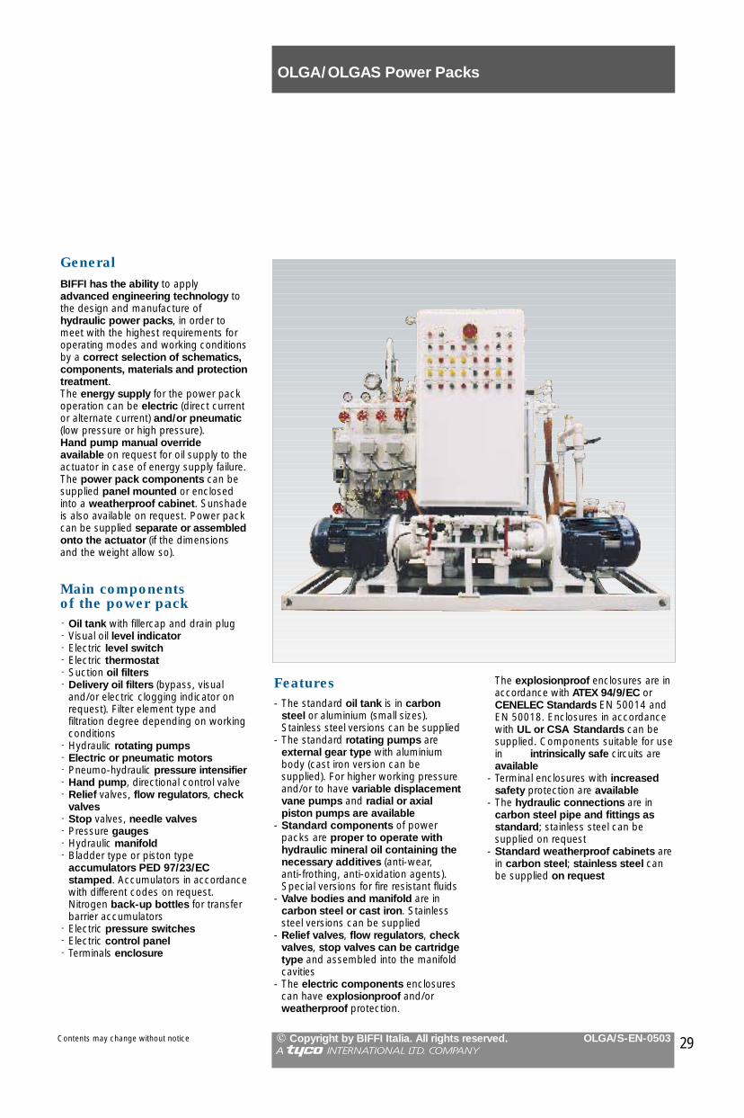
GeneralBIFFI has the ability to apply advanced engineering technology tothe design and manufacture of hydraulic power packs, in order tomeet with the highest requirements foroperating modes and working conditionsby a correct selection of schematics, components, materials and protectiontreatment. The energy supply for the power packoperation can be electric (direct currentor alternate current) and/or pneumatic(low pressure or high pressure).Hand pump manual override available on request for oil supply to theactuator in case of energy supply failure.The power pack components can besupplied panel mounted or enclosedinto a weatherproof cabinet. Sunshadeis also available on request. Power packcan be supplied separate or assembledonto the actuator (if the dimensionsand the weight allow so).
Main components of the power pack- Oil tank with fillercap and drain plug- Visual oil level indicator- Electric level switch- Electric thermostat- Suction oil filters- Delivery oil filters (bypass, visual
and/or electric clogging indicator onrequest). Filter element type and filtration degree depending on workingconditions
- Hydraulic rotating pumps- Electric or pneumatic motors- Pneumo-hydraulic pressure intensifier- Hand pump, directional control valve- Relief valves, flow regulators, check
valves- Stop valves, needle valves- Pressure gauges- Hydraulic manifold- Bladder type or piston type
accumulators PED 97/23/EC stamped. Accumulators in accordancewith different codes on request.Nitrogen back-up bottles for transferbarrier accumulators
- Electric pressure switches- Electric control panel- Terminals enclosure
The explosionproof enclosures are inaccordance with ATEX 94/9/EC orCENELEC Standards EN 50014 andEN 50018. Enclosures in accordancewith UL or CSA Standards can besupplied. Components suitable for usein intrinsically safe circuits areavailable
- Terminal enclosures with increasedsafety protection are available
- The hydraulic connections are in carbon steel pipe and fittings as standard; stainless steel can be supplied on request
- Standard weatherproof cabinets arein carbon steel; stainless steel canbe supplied on request
Features- The standard oil tank is in carbon
steel or aluminium (small sizes).Stainless steel versions can be supplied
- The standard rotating pumps areexternal gear type with aluminiumbody (cast iron version can be supplied). For higher working pressureand/or to have variable displacementvane pumps and radial or axialpiston pumps are available
- Standard components of powerpacks are proper to operate withhydraulic mineral oil containing thenecessary additives (anti-wear, anti-frothing, anti-oxidation agents). Special versions for fire resistant fluids
- Valve bodies and manifold are in carbon steel or cast iron. Stainlesssteel versions can be supplied
- Relief valves, flow regulators, checkvalves, stop valves can be cartridgetype and assembled into the manifoldcavities
- The electric components enclosurescan have explosionproof and/orweatherproof protection.

OLGA/OLGAS Accessories Mounting Holes
� Copyright by BIFFI Italia. All rights reserved. OLGA/S-EN-0503A !@#$ INTERNATIONAL LTD. COMPANY
Contents may change without notice
JH
C
øD
Q
N
øP
M
L
A
B
F
E
GS
R
Flow line
top view
Mounting holes of cover and yoke
Mounting holes of housing
front side
back side
front side
side view
Yoke
top view
Model A B C øD E F G H J L M N øP Q R S0.3 77.5 155 60 14 5 113 119 37 12 92 200 60 14 36 5 2000.9 92.5 185 60 14 5 155 170 61 35 85 200 60 14 48 5 2431.5 92.5 185 60 14 5 175 185 62 35 130 300 100 14 45 5 2843 117.5 235 85 23 8 203 215 57 25 230 500 100 14 54 5 3716 137 455 115 23 8 248 260 59 22 224 500 100 14 87 8 48014 315 630 200 27 10 227 330 97 55 220 500 170 27 99 8 54318 315 630 200 27 10 235 340 72 32 306 680 215 27 80 10 60032 315 630 200 27 10 385 395 72 32 414 890 215 27 149 10 66050 387.5 860 250 30 12 372 387 77 35 473 1030 215 27 163 10 1072
Dimensions in mm
Model A B C D E øF G H J øL M øN P R0.3 140 70 70 No. 4 x M10 10 84 6 6 19 - No. 4 x M4 76 - 70.9 140 70 70 No. 4 x M10 12 102 6 6 19 11 No. 4 x M4 93 22 71.5 140 70 70 No. 4 x M10 12 133 6 6 19 11 No. 4 x M5 122 22 73 160 127 136 No. 4 x M16 12 184 6 6 19 - No. 4 x M6 171 - 106 160 127 136 No. 4 x M16 13 232 6 6 19 16.5 No. 4 x M6 216 30 1014 160 127 136 No. 4 x M16 16 232 6 6 19 - No. 4 x M6 216 - 1018 314 109 109 No. 4 x M16 18 255 6 6 16 16.5 No. 4 x M6 240 35 1032 314 109 109 No. 4 x M16 16 265 6 6 16 16.5 No. 4 x M6 250 33 1050 280.6 138.5 138.5 No. 4 x M20 18 295 6 6 16 20.5 No. 4 x M6 278 46 10
The index is shown for actuator in end position (fully open or closed)
Dimensions in mm
øF
øN
øL DA
M
D
XHJ
G-0
.1-0
.2
Index (removable)
Control panel or cabinet
HousingCoverCover
Detail X: for models0.3, 3, 14
Detail X: for models0.9, 1.5, 6, 18, 32, 50B
R R
P
C
M DE
M
E
30

notes .......................................................................................................................................................................................................................................................................................................................................................................................................................................................................................................................................................................................................................................................................................................................................................................................................................................................................................................................................................................................................................................................
OLGA/OLGAS Enquiry and Ordering Data
Contents may change without notice � Copyright by BIFFI Italia. All rights reserved. OLGA/S-EN-0503A !@#$ INTERNATIONAL LTD. COMPANY
Your enquiries for hydraulic actuators can be efficiently processed when you supply the informationrequested on this page.Please use this page as guidance when sending yourenquiries; if you need assistance, directly contact ouroffices.
Applicable documents
Valve data
Actuator data
Customer requisition n° ...............................................................................................
Data sheet ...................................................................................................................
Specification ................................................................................................................
Manufacturer ........................................Model ..................Type .........................Size: ND ............... � mm � inchesClass ....................................................Max diff. pressure ............. � bar g
� PSIMedium ................................................Service � on-off � modulating
� ............................................
Valve required torques� Nm � Lbs-in
safety factor: included ........% � not incl.break to open (0°) .................................break to close (90°) ...............................end to close (0°) ....................................end to open (90°) ..................................running ................................................dynamic torque (at.....°) ........................max allowable .......................................
Stem sizediameter/square side ......................mmheight .............................................mmkey dimension ............... x ..............mmCoupling dimensionscustomer's drawing ..............................Installationpipe axis: � vertical � horizontalvalve stem: � vertical � horizontalcylinder axis: � parallel � perpendicular
to the pipe axis
Actuator type� double acting� single acting spring to close� single acting spring to open
Supply� mineral oil � ..........................
viscosity ...........cSt at ........ � °C � °Foil type/brand ...............................connections size: .............. � ISO7/1Rp
� NPT� ..............
Oil supply pressure: � bar g� PSI
min ........... normal ........... max ............
Operating time (sec)opening: from .................. to ...............closing: from .................. to ...............Ambient temperaturemin ........... max ............ � °C � °FEnvironment conditions .......................Required painting cycle .......................Manual override:� no � jackscrew � hand pump� ..........................................................
31
Notes
.............................................................................................................................................................................................................
.............................................................................................................................................................................................................
.............................................................................................................................................................................................................
.............................................................................................................................................................................................................
.............................................................................................................................................................................................................

Control system
On-off service� by electric signal� by local manual control� ..........................................................1 signal � to close � to open2 signals � to close � to openControl signal: voltage .............. � DC
.............. � AC ........... Hznotes .................................................................................................................................................................................
Modulating service� by electric signal ..... mA (closed valve)
..... mA (open valve)� ..........................................................
..........................................................
Control system reset� automatic � local manual� remote .................................� after any closing operation� after any opening operation� after emergency operation only
Emergency action� closing operation� opening operation� stay in position� for hydraulic supply failure� ..........................................................� for low pressure in the process line� for high pressure in the process line� for electric supply failurefor electric control signal
� failure� present from remote control station
� ..........................................................
Control system components
Solenoid valvesBody material� carbon steel/cast iron� stainless steel� ..........................................................Action� direct � servopilotedCoil enclosure protection� weatherproof IP ................................� explosionproof ................................................................................................� intrinsically safe ..................................code: � CENELEC � ATEXCoil enclosure material� aluminium � cast iron/steel� ..........................................................Function� NC � NO � ..........................Supply voltage ............. � DC
............. � AC ..... HzMax consumed power ...... � W � VAnotes ..................................................... ..............................................................
Pipe and fittings� carbon steel� 316 stainless steel� ..........................................................notes ..................................................................................................................
Junction boxProtection degree� weatherproof IP ................................� explosionproof ..................................� intrinsically safe ..................................� increased safety ................................code: � CENELEC � ATEXMaterial� aluminium � cast iron � GRP� stainless steel � ...........................Cable entries� q.ty .................... size ........................
Customer operating diagram ..............Customer wiring diagram ....................notes .....................................................
Control system valvestype � spool � poppet � ................body material � carbon steel/cast iron� stainless steel � .................................notes .................................................................................................................
Control system assembling�on panel:
panel material �carbon steel (std)� stainless steel
� into cabinet: cabinet material �carbon steel (std)
� stainless steelnotes .............................................................................................................................................................................................................................................................................................................................................................................................................................................................................................................................................
OLGA/OLGAS Enquiry and Ordering Data
Contents may change without notice
type � bladder � piston � ..............no. of strokes ....................................... starting pressure ........... � bar g � PSIcode:� PED � TÜV � ASME VIII Div.1 not stamped� ..........................................................
design pressure ........... � bar g � PSIdesign temperature .......... �°C �°Faccessories ..................................................................................................................................................................................................................................................................................................
notes .......................................................................................................................................................................................................................................................................................................................................................................................................................................
Accumulator
� Copyright by BIFFI Italia. All rights reserved. OLGA/S-EN-0503A !@#$ INTERNATIONAL LTD. COMPANY
32
Valve position signaling
Electric limit switchesopen q.ty ............ closed q.ty ................intermediate q.ty ...................................Supply voltage .......... � DC
.......... � AC ........ Hzload:resistive .................................... Ampslamps .................................... Ampsinductive .................................... AmpsCam actuated�SPDT �sealed �sealed under inert gas� gold contact � DPDT � ................Proximity� inductive� magnetic � NO � NC � SPDTtype/manufacturer .................................
Electric position transmitter� 4-20 mA output signal �contact type� contactless type � ...................� resistive from ............ to .......... Ohm� ..........................................................type/manufacturer ................................notes .................................................................................................................................................................................................................................................................................................................................................................................................................................................................................................................................................................................................................................
Local position indicator� standard� special ..............................................EnclosureProtection degree� weatherproof IP.................................� explosionproof ................................................................................................� intrinsically safe .................................code: � CENELEC � ........................Material� alum. (std) � cast iron � .............Cable entriesq.ty ......................... size ......................
Customer wiring diagram ....................

............................................................................................................................................................................................................
............................................................................................................................................................................................................
............................................................................................................................................................................................................
............................................................................................................................................................................................................
............................................................................................................................................................................................................
............................................................................................................................................................................................................
............................................................................................................................................................................................................
............................................................................................................................................................................................................
............................................................................................................................................................................................................
............................................................................................................................................................................................................
............................................................................................................................................................................................................
............................................................................................................................................................................................................
............................................................................................................................................................................................................
............................................................................................................................................................................................................
............................................................................................................................................................................................................
............................................................................................................................................................................................................
............................................................................................................................................................................................................
............................................................................................................................................................................................................
............................................................................................................................................................................................................
............................................................................................................................................................................................................
............................................................................................................................................................................................................
............................................................................................................................................................................................................
............................................................................................................................................................................................................
............................................................................................................................................................................................................
............................................................................................................................................................................................................
............................................................................................................................................................................................................
............................................................................................................................................................................................................
............................................................................................................................................................................................................
............................................................................................................................................................................................................
............................................................................................................................................................................................................
............................................................................................................................................................................................................
............................................................................................................................................................................................................
............................................................................................................................................................................................................
............................................................................................................................................................................................................
............................................................................................................................................................................................................
............................................................................................................................................................................................................
............................................................................................................................................................................................................
............................................................................................................................................................................................................
............................................................................................................................................................................................................
............................................................................................................................................................................................................
............................................................................................................................................................................................................
............................................................................................................................................................................................................
............................................................................................................................................................................................................
............................................................................................................................................................................................................
............................................................................................................................................................................................................
............................................................................................................................................................................................................
............................................................................................................................................................................................................
............................................................................................................................................................................................................
............................................................................................................................................................................................................
............................................................................................................................................................................................................
............................................................................................................................................................................................................
............................................................................................................................................................................................................
............................................................................................................................................................................................................
............................................................................................................................................................................................................
............................................................................................................................................................................................................
............................................................................................................................................................................................................
............................................................................................................................................................................................................
............................................................................................................................................................................................................
............................................................................................................................................................................................................
............................................................................................................................................................................................................
............................................................................................................................................................................................................
............................................................................................................................................................................................................
............................................................................................................................................................................................................
............................................................................................................................................................................................................
............................................................................................................................................................................................................
............................................................................................................................................................................................................
............................................................................................................................................................................................................
............................................................................................................................................................................................................
............................................................................................................................................................................................................
............................................................................................................................................................................................................
Notes
Contents may change without notice � Copyright by BIFFI Italia. All rights reserved. OLGA/S-EN-0503A !@#$ INTERNATIONAL LTD. COMPANY
33

Biffi Italia S.r.L. - Località Caselle S. Pietro - 29017 Fiorenzuola d’Arda (PC) - ITALYTel (0523) 944411 - Fax (0523) 941885 / 943923 / 944500
e_mail: [email protected]