Embed Size (px)
Citation preview

1
Older Jeep Brakes 101 John Gibbins M.I.A.M.E. (Artificer) KCQ Automotive Services Pty Ltd
ABN 28084145942
Sketches and diagrams are courtesy of the Derek, Bryce, the odd g503 post, Bendix, Snap On, TM’s plus publishing assistance from Jon Rogers appreciated.
Some of this information is compatible with many US and Canadian manufactured WWII Vehicle basic braking systems up to and including some 6x6 trucks. The jeep braking system is fairly simple compared with modern variants but there are some idiosyncrasies and basic stuff one should/must know about. There is no rocket science and one shouldn’t need specialists to help overhaul or work on their braking systems. Basics: § Fluid is held in a contained system and a force applied by the push rod to the
master cylinder piston is transferred to other (restrained) points in the system (wheel cylinders and shoes).
§ Fluids can’t be compressed (for our purposes)…..Brake pedal will feel HARD or solid on application (if the pedal goes near floor and you can pump up the pedal by quick repetitive applications and the pedal feels HARD all the time…….there is a need to adjust)
§ Air can be compressed…..Brake pedal will feel SOFT or spongy (if a pedal can be pumped up but still feels spongy…. Establish how air got into the sealed system, usually low or no fluid in the reservoir. Find and fix leaks, refill and bleed)
§ Generally brake fluids are hydroscopic and will absorb moisture from air (atmospheric pressure on top of reservoir fluid).
§ If fluid is not changed on a regular basis (like 2 years or less) the water will eat away at and destroy wheel and master cylinders.
PDF created with pdfFactory trial version www.pdffactory.com

2
§ The fluid you choose is your prerogative as long as it is brake system suitable.
DOT 3 or 4 although but nothing is wrong with DOT5 or later variants in a new/rebuilt system and do not mix fluids or types.
§ Rubbers (and other compounded materials) are used to seal braking systems, maintain the system integrity, on pedal application as well as to keep contaminants out.
§ These sealing components “hate” mineral oils and should not be exposed to them even with dirty hands when handling and fitting (use special purpose rubber grease/methylated spirits or alcohol….. FLAMABLE).
§ These rubber components if exposed to mineral products will swell up become soft, spongy, disintegrate and can block ports.
§ Balance is important when working on brakes:
o If one wheel cylinder fails then others will be close, so do them all o If a drum needs resizing do them in pairs at least, preferably all o If drums are resized you need to match with oversize linings o Linings must be replaced in axle pairs and preferably both axles o Oil/fluid damaged linings can’t be restored by shade tree methods o Most current WWII Jeep brake related issues are caused by fluid
contamination or fluid loss o Pretty commonsense stuff.
PDF created with pdfFactory trial version www.pdffactory.com

3
MASTER CYLINDER
The master cylinder is made up of the following parts: Master Cylinder and components § 1. Cast body with vented filler cap and copper/aluminium gasket seal (bore
can be reclaimed with stainless steel or brass sleeve and sometimes honing) § 2. Aluminium piston with holes and a thin copper plate flush riveted to the
main face (which mates up with the primary cup or seal) § 3. The piston is retained in a returned position with a spacer then a circlip. If
the spacer is left out this will show up as too much pedal travel before braking commences when other adjustments all appear correct.
§ 4. Rear or Secondary cup (which will leak around the dust boot if faulty. Provided there is sufficient fluid in the reservoir will not cause brake failure or loss of braking).
§ 5. Primary cup or seal has a brass shim between it and the piston copper plate (Shim must be in place. Also total loss of brakes or pedal slowly sinking to the floor are symptoms of a failed or failing primary cup)
§ 6. Two holes are in the reservoir through to the cylinder
PDF created with pdfFactory trial version www.pdffactory.com
4
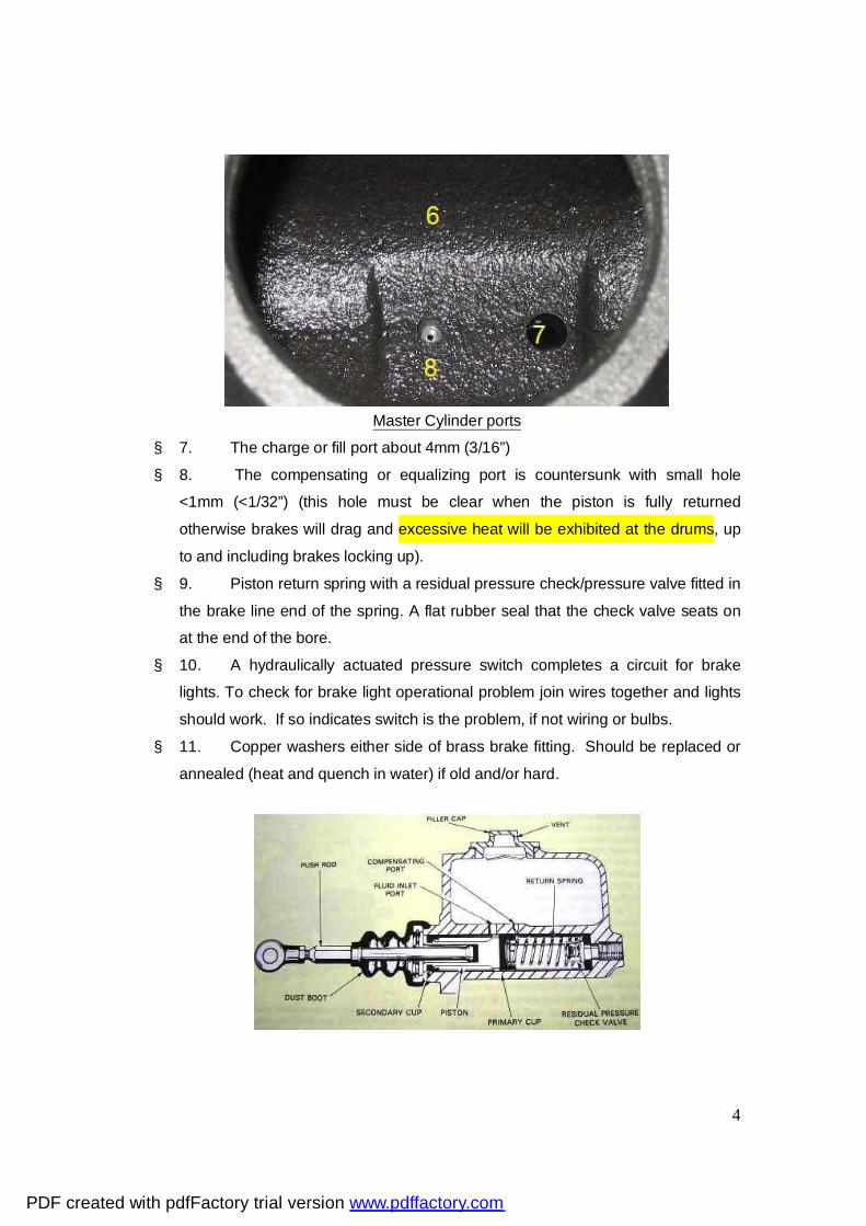
Master Cylinder ports
§ 7. The charge or fill port about 4mm (3/16”) § 8. The compensating or equalizing port is countersunk with small hole
<1mm (<1/32”) (this hole must be clear when the piston is fully returned otherwise brakes will drag and excessive heat will be exhibited at the drums, up to and including brakes locking up).
§ 9. Piston return spring with a residual pressure check/pressure valve fitted in the brake line end of the spring. A flat rubber seal that the check valve seats on at the end of the bore.
§ 10. A hydraulically actuated pressure switch completes a circuit for brake lights. To check for brake light operational problem join wires together and lights should work. If so indicates switch is the problem, if not wiring or bulbs.
§ 11. Copper washers either side of brass brake fitting. Should be replaced or annealed (heat and quench in water) if old and/or hard.
PDF created with pdfFactory trial version www.pdffactory.com

5
How it all works § Atmospheric pressure must be available to the m/c brake fluid on all brake
systems. Some later systems avoid air coming into contact with the brake fluid by using a flexible membrane separating the two.
§ There should be no more that 10mm (1/2”) free travel at the pedal before the m/c push rod engages the piston. As long as there is “a” clearance between the push rod and the piston (like the thickness of a hacksaw blade) that is enough as long as the pedal return spring is in place. This is to ensure the rearward piston travel uncovers the compensating/equalizing port.
Pedal return spring and other stuff
§ On application the piston moves forward a very small amount and the primary
seal closes the compensating/equalizing port creating a fully sealed system. § There can be a small surge of fluid in the master cylinder before the seal covers
this port. § As fluid is incompressible (as far as we are concerned) it moves as a solid
medium opening the little check valve and pushing out the sealing cups and pistons in the wheel cylinders applying the shoes to the brake drums.
§ At this point (when the shoes contact the drums) pressure starts to build. § If the pedal feels hard, that is good. § If it is spongy there is the possibility of air in the system. § When the pedal is released the brake shoe return spring retracts the shoes
(unless you have binding or seized w/c/s) forcing back the m/c piston and diminishing the pressure in the system.
PDF created with pdfFactory trial version www.pdffactory.com
6
§ This creates a lower than atmospheric pressure in the previously sealed system as the fluid pressurized in the system can’t get back into the reservoir quickly enough (small equalising port won’t let this happen so don’t go drilling this out or thinking something’s wrong)
§ As the piston moves back quickly the charging/fill port, at atmospheric pressure allows adequate supply of fluid which flows through those little holes in the piston collapsing the primary cup and filling the “void”.
§ This eliminates any problems with the need for repeated quick applications. It also explains why a HARD pedal comes up higher when brake adjustment is needed.
§ What is happening is we are adding an extra amount of fluid to the lines before everything has fully returned to its rest position and in effect the brakes are dragging.
§ You will now understand why the copper valve plate (and brass shim) is in front of the piston. If they weren’t the rubber would be eroded away like a bottle top (cap) after extended service causing non sealing and “brake failure” on application.
§ Signs would be the pedal sinking to the floor on application and fluid return through both ports exhibited in the m/c reservoir while applying.
§ This does not feel the same as air in the system and there could be no visible fluid loss.
§ The piston and primary seal when fully retracted uncover the compensating/equalizing port, atmospheric pressure is on all fluid and any extra returns to the reservoir through the small compensating port hole and the system is ready to do it all again.
§ The little check valve in front of the piston return spring (shown in the diagram) reseats and maintains a line pressure of about 25kPa (3-4psi) above atmospheric, not enough to cause brakes not to return but enough to cause the w/c seals to be kept nice and tightly in place ready to go to work again. Land Rover never learned this early which is the reason they were nearly impossible to bleed using accepted bleeding practices back then!
PDF created with pdfFactory trial version www.pdffactory.com

7
MASTER & WHEEL CYLINDER SERVICING § Repair kits are available and sometimes the m/c and w/c’s can be reclaimed by
re-sleeving or honing and fitting these kits
§ Oversize cups are not available, as they once used to be. § Honing is not meant to remove much material at all just clean up the bore which I
would use fine steel wool on first. § If there is any pitting or indentations remaining in the bore caused by corrosion
(or whatever) the cylinder is not re-useable without re-sleeving. § Fit up overhauled cylinders with special purpose rubber grease (no mineral
product allowed). § Keep in mind the weakest link will fail and when that is repaired the next weakest
will fail. § RECOMMENDATION is all or nothing. § Brakes are one area to do best the first time and save bucks down the line. § Shop labour costs in repairing will be higher than buying all new stuff and doing it
yourself. § Sleeving is a great (one time real expensive) option to keep original and get long,
long life.
PDF created with pdfFactory trial version www.pdffactory.com

8
STEEL BRAKE LINES § These are made up of special steel tube made for brake lines, double flared at all
extremities. They should not be made from copper or single flared. In some cases stainless steel lines are used when salted roads and corrosion are issues.
Double flared steel brake tube
§ With the right flaring tool you can do it yourself with some practice. § Some little “S” bends are a little harder than straight lines as we know! § Bending should be done with special benders and in some cases inside coiled
springs meant for that purpose. § In some applications the coils are left in place to avoid stone damage to the lines. § Without you will kink and ruin the tube, so don’t try! § All lines should be fixed with original type clamping (or similar) in all original
positions. Fatigue and failure if not done properly.
PDF created with pdfFactory trial version www.pdffactory.com

9
FLEXIBLE BRAKE LINES § Flexible lines have a use by date and NOS should be avoided. § When hand bent or twisted if there is evidence of fatigue or perishing they should
be discarded and NEW stock ones fitted.
§ Old hoses may show up as a softer, spongy brake pedal. § All original style clips and attachments must be in place. § Appropriate tools and techniques should be used when removing and replacing
parts
PDF created with pdfFactory trial version www.pdffactory.com

10
BRAKE DRUMS § Original brake drums have a slot for feeler gauge measurement on adjustment
with wheels off. § This facility is not too effective with badly worn or machined drums. § New stock drums sometimes don’t have these slots (see section on adjustment)
Feeler slot
§ Are hub mounted using the wheel mounting studs swaged so the hub and drum become one part.
§ The drums can be machined through various O/S to manufacturer’s limits and then replaced.
§ Drums should be machined the same dimensions in a minimum of pairs preferably all 4. The drums and mounting studs (which are the wheel studs as well) are serviceable.
§ The drums which become worn beyond limits, oval and bell shaped in service if outside specification limits need to be replaced. This requires separation of the swaged components.
PDF created with pdfFactory trial version www.pdffactory.com

11
Swage Remover
Full Swage Removal Partial Swage
§ There are some rough and ready ways to remove studs but I recommend you use a tool, like this one from Bryce of “run forest run” in a low geared slow running drill, to relieve the effects of swaging. This will allow you to press out the old stud more easily and safely. If you insist on using a hammer (persuader) it will be easier and less dangerous if the burring or swage is removed and remember safety glasses.
§ New drums and studs should be fitted on perfectly clean flat surfaces between hub and drum and re-swaged when installed.
§ This fitting should be done with a press (support mounted under the wheel stud/s head/s suggest a piece of 4” x 4” hardwood just short of the drum dia and moving to suit) and a short piece of pipe which fits neatly over the stud thread and just longer than the thread when fully home. Deep socket?
§ Bushy style with a persuader is not recommended but some will insist. § Either way is critical and if incorrectly implemented may require a complete re-do
or new drums to be skimmed to round!
PDF created with pdfFactory trial version www.pdffactory.com
12
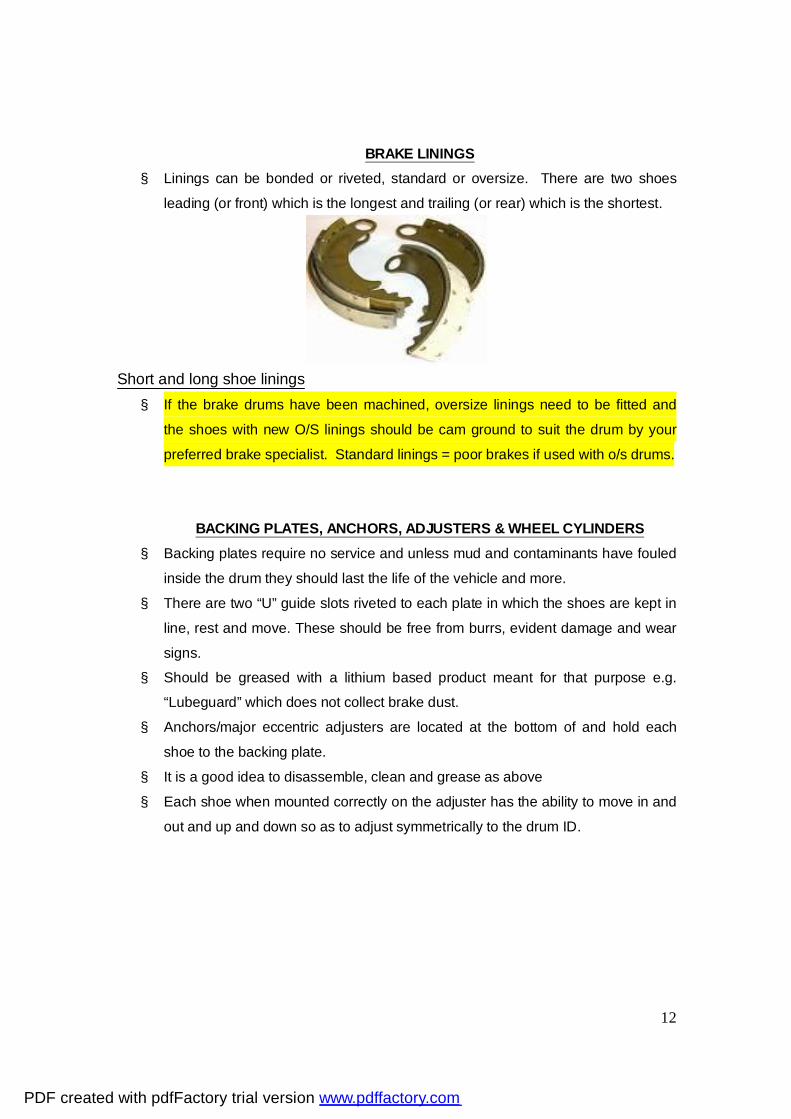
BRAKE LININGS § Linings can be bonded or riveted, standard or oversize. There are two shoes
leading (or front) which is the longest and trailing (or rear) which is the shortest.
Short and long shoe linings § If the brake drums have been machined, oversize linings need to be fitted and
the shoes with new O/S linings should be cam ground to suit the drum by your preferred brake specialist. Standard linings = poor brakes if used with o/s drums.
BACKING PLATES, ANCHORS, ADJUSTERS & WHEEL CYLINDERS § Backing plates require no service and unless mud and contaminants have fouled
inside the drum they should last the life of the vehicle and more. § There are two “U” guide slots riveted to each plate in which the shoes are kept in
line, rest and move. These should be free from burrs, evident damage and wear signs.
§ Should be greased with a lithium based product meant for that purpose e.g. “Lubeguard” which does not collect brake dust.
§ Anchors/major eccentric adjusters are located at the bottom of and hold each shoe to the backing plate.
§ It is a good idea to disassemble, clean and grease as above § Each shoe when mounted correctly on the adjuster has the ability to move in and
out and up and down so as to adjust symmetrically to the drum ID.
PDF created with pdfFactory trial version www.pdffactory.com
13
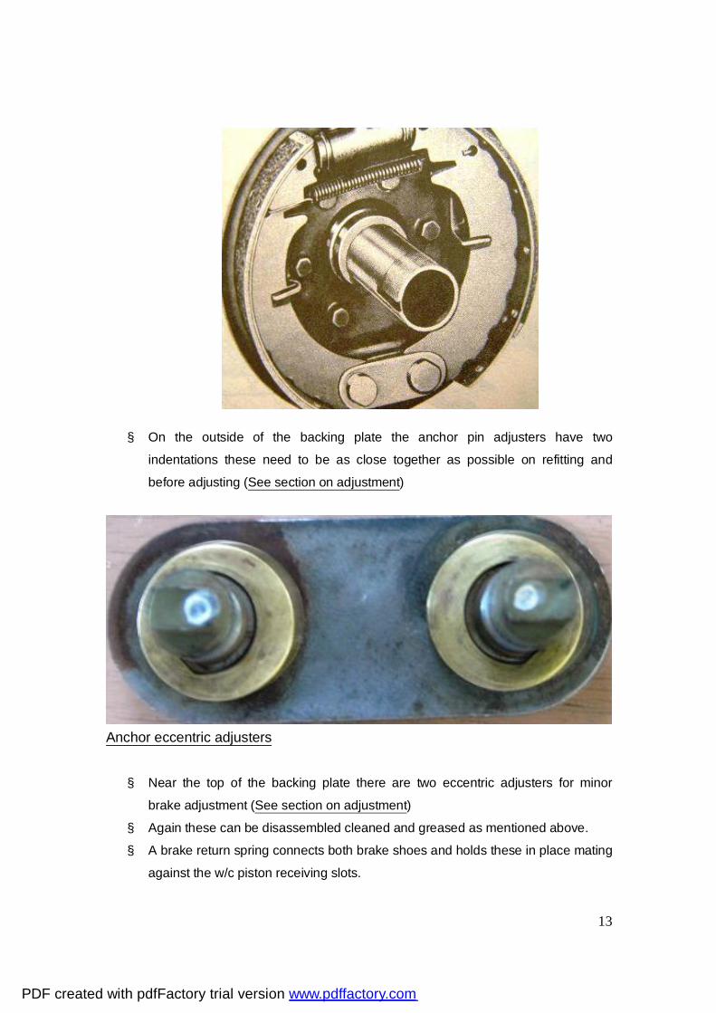
§ On the outside of the backing plate the anchor pin adjusters have two indentations these need to be as close together as possible on refitting and before adjusting (See section on adjustment)
Anchor eccentric adjusters § Near the top of the backing plate there are two eccentric adjusters for minor
brake adjustment (See section on adjustment) § Again these can be disassembled cleaned and greased as mentioned above. § A brake return spring connects both brake shoes and holds these in place mating
against the w/c piston receiving slots.
PDF created with pdfFactory trial version www.pdffactory.com

14
WHEEL CYLINDERS § There are two (2) diameter wheel cylinders and the larger 1” is always fitted to
the front axle as more braking force is needed there because of weight transfer. Rear are ¾”
§ The w/c contains a light spring keeping two w/c rubbers and pistons apart. § The flat rubber surface fits against the flat piston surface § Each w/c contains a bleed screw which most folk like to over tighten. Suggest
just nip them up, light tension put on the rubber dust cap and seal around the thread with a thick paint. Next guy to touch then won’t snap them off. Curses!
§ There are aftermarket bleeders available with a one way check valve recommended by some to help with bleeding, especially when unassisted although I don’t believe they are really needed. (see bleeding)
§ Why do wheel (and master cylinders) leak? § Would you believe it is usually something you do or have done? § Think about it!!!
PDF created with pdfFactory trial version www.pdffactory.com

15
BLEEDING BRAKES I would normally try adjusting before bleeding. Altering adjustments can cause w/c rubbers (seals) to travel in part of the cylinder they normally wouldn’t and become damaged, then leak. Just like can happen when new pads are fitted to disc callipers and the piston has to be fully retracted. Then one finds leaks which weren’t there before because the seal has become damaged.
§ Brake fluid will remove paint, so be very careful. § Also it is not too good for body parts
§ The reason we bleed brakes is generally to remove and replenish atmospherically contaminated fluid (every year to two) or
§ To add make up fluid if there has been a leak or repair done to the brake system. § Recommended/preferred method: Vacuum evacuation and replenishment
§ Vacuum pumps (hand operated) can be obtained very inexpensively, if you don’t
have one from Pep Boys, HF, JC Whitney’s, NAPA and similar auto supply stores.
§ The reason I recommend vacuum is because: § The m/c piston and rubbers normally don’t travel very far in the cylinder <1/4”. § Over time trash accumulates in front of the primary cup in the non travelled
section. § If a bleeder is opened and the pedal sinks right to the floor when applied you will
more than likely damage the seal as it will be running over a rough surface instead of in a smooth bore.
§ If this occurs you will need to overhaul or replace the master cylinder, something you weren’t planning on doing.
PDF created with pdfFactory trial version www.pdffactory.com

16
§ Similar consequences in w/c when new linings are fitted § Vacuuming can be done alone and no-one needs to pump the m/c pedal so the
seal does not have to move at all. § If you have or are choosing to use DOT 5 in a rebuilt system, vacuum will not add
air to the fluid § Fill m/c with same fluid specification as you currently have. § A differing colour is preferred, for obvious reasons. § Recap the m/c. § Remove the rubber caps off all bleeders (don’t forget to put them back when you
are finished). § With a copper/lead mallet give each bleed screw I nice square on disturbance
(not too hard, just enough shock to loosen things up) § Clean any dirt out of the centre of the bleeder with a suitable drill bit turning by
hand (no power tools) § With a full hex ring or box wrench just ensure all the bleed screws can be
loosened about ½ turn using the correct size and re-tighten lightly. (there can be variances in head sizes)
§ Bleed order is: RR/RF/LR/LF § If fluid is not coming out when vacuum is applied it has been known for Billy Bob
to block off a leaking wheel cylinder line with a strategically placed ball bearing, lead fishing sinker or rivet.
§ Also you may have to remove the bleeder and clean the little bleeder hole. § Hook up your hand operated vacuum pump to each bleeder in turn. § Loosen bleeder ½ a turn or maybe a little more and apply vac until new colour or
clear clean fluid appears. § Lock off and replace dust seal and so on. § Depending on the amount of fluid you are removing to get good clean stuff, you
may need to top up the master cylinder during the bleeding process and re-cap. § Wipe around the thread of the bleeder and apply a thick paint seal. § The reason we do this is to exclude air from getting to any brake fluid which may
be on the bleeder thread and will cause them to rust in place (always think of next time)
§ When complete top up m/c and recap. (20-45 minutes max)
PDF created with pdfFactory trial version www.pdffactory.com

17
ADJUSTMENT of JEEP BRAKES (hydraulic)
Derek’s Tools & someone’s improvising
Note Derek’s modified ring spanner (box wrench) § IMPORTANT:
o Before any adjustment the foot pedal free play must be correct and the pedal return spring in place as explained in the section on m/c.
o The brakes must be normalized and not HOT. o Wheels must be off the ground preferably on stands, in neutral,
handbrake off and not dragging. o Check shoes are not dragging.
§ There are two types of adjustment:
PDF created with pdfFactory trial version www.pdffactory.com

18
MINOR ADJUSTMENT Minor for normal in-service adjustment § Method:
Everything done as listed previously in IMPORTANT § Lightly loosen the forward located (leading) brake shoe eccentric lock nut with a
ring spanner (box wrench) and leave it in place so that you can retighten in one (1) go. We are talking of the top adjuster!
§ There is a special tool (Snap On) 3/16” or equivalent metric OE wrench (my kit does not go down that far) and at worse a 100mm (4”) shifter or adjustable and no bigger will do the job.
§ “If” the top adjuster has a dimple and it is away from the wheel, the cam is off § The adjuster should not feel real tight, if it does loosen the lock nut further
(slightly) and do not get a bigger (more leverage) type tool 3-4” is enough. § Usually you are not turning too much but should the thread tend to tighten the
locknut, loosen a little more.
PDF created with pdfFactory trial version www.pdffactory.com

19
§ The cam is symmetrical so you can turn either way but it is best to get used to a
certain method e.g. out toward the wheel for the front (leading) and back toward the wheel at the rear (trailing) then when you adjust next time you turn the same way and get immediate results.
§ Turn the adjuster until the shoe just locks the drum, then in the opposite direction to loosen until the wheel just turns freely.
§ There is a very small difference between just locked and turning freely. § With the wrench held in place on the adjuster, retighten the adjuster lock nut. That is
why we left the ring spanner in place! § Check the wheel turns freely and mark adjuster with chalk as completed. § Systematically do all wheels should take < ½ hour or maybe an hour maximum with
a couple of stubbies (beers).
PDF created with pdfFactory trial version www.pdffactory.com

20
MAJOR ADJUSTMENT Major normally done after dismantling and some serious type maintenance with the vehicle on stands and wheels off.
Adjusters in cam off position Turn both down at the dimple to start your major adjustment § This adjustment realigns shoes with the drums after re-line, drum skimming, new
drums and the like. § OEM drums are slotted to fit feeler gauges to measure clearances; some
aftermarket drums do not have these slots. § If the drums are worn and linings are scored or there is no slot go straight to the
section NO SLOT METHOD § One could drill a centre popped small hole (1/16”) depth limited in each drum so
that wire gauges could do the job, being extremely careful not to drill into the finish drum to shoe bore.
PDF created with pdfFactory trial version www.pdffactory.com
21
§ All the IMPORTANT things done? § You can do your MINOR ADJUSTMENT as related above and the top major
reading .008” should be pretty right but recheck anyway. § Major Adjustment is accomplished by turning the anchor pin dots toward each
other and then down until the shoes are set to the proper clearance using a feeler gauge
§ The recommended shoe setting is .008” at the toe (upper end) and .005 clearance at the heel (lower end) each 25mm (1”) in from the lining extremity
§ Loosen the anchor lock nut on the forward primary shoe (not too much) leaving the wrench attached (notice how Derek has a permanently modified and shaped a wrench to fit on page 15).
§ With the feeler slot or drill hole 25mm (1”) in from the end of the toe (top) of the leading shoe check and adjust for .008” by turning the anchor dot downward
§ Move the drum so as to have the slot 25mm (1”) from the bottom (heel) of the same shoe, check and adjust to .005.
§ Tighten the locknut not allowing the anchor bolt to move while doing so otherwise the adjustment will alter
§ Check for drag and if dragging do again § Mark locknut with chalk when done § Then do each other shoe on the vehicle the same way remembering that the
trailing shoes are shorter so the position of the feeler will be different
PDF created with pdfFactory trial version www.pdffactory.com

22
NO SLOT ADJUSTMENT METHOD § I will offer another method not requiring the slots or drill holes lifted in part from a
WWII publication related to light Chevy Blitz trucks (thanks to Jimmy Sewell, an old buddy from TAFE days) which is simple, quick and easy. Presumably it will work on Ford GPW’s with no ill effects envisaged!
All the IMPORTANT things done?
§ Do your minor adjustment as related above § Apply a force of 25-35# to the brake pedal. This force must be consistent and
maintained through out the entire adjustment. § This is not much force; place a small piece of wood in between the pedal shaft in
the engine compartment and the firewall holding the pedal down slightly and consistently just past free play.
§ This force moves the m/c piston enough to close the compensating or equalising port but not move the wheels cylinder pistons!
§ All bottom anchor pin dimples should be as close as they can be together (adjacent to one another)
§ When their locknuts are loosened we use the system of leaving the ring spanner (box wrench) on the anchor lock nut as we did above
§ Adjust each of the 8 anchor pins (in turn) moving the dimple downward with no
more than 3” long wrench until the shoe just touches, indicated by very slight interference when turning the drum, back off a fraction
§ Tighten the anchor pin lock nut as you complete each one ensuring the anchor pin does not move and mark as done with chalk
PDF created with pdfFactory trial version www.pdffactory.com

23
§ Remove the wood block from under the brake pedal shaft and make sure all the brake drums turn with absolute minimal to no dragging.
§ They must all feel the same. § If the shoes drag you need to do it again. Be more careful this time as 4 stubbies
(beers) affects concentration! § Road test when under .05 in an area with little traffic. After a little bedding in try a
few repeated hard applications. § Pulling up in a straight line, you’re a winner or no then re-adjust!
EXTERNAL CONTRACTING HANDBRAKE ADJUSTMENT
§ The handbrake adjustment is not difficult and this type of park brake system is
very effective if properly adjusted. § One thing to be aware of is that many people have played with your vehicle
before you and there is no guarantee everything is in place properly, is to specification and some bits may be missing altogether.
§ 1. Check the operation of the handbrake lever and pawl locking mechanism. Note: When applying the h/b always turn handle ¼ turn (the same as you do when releasing) then turn back to lock when application is complete. This will save pawl wear and tear.
PDF created with pdfFactory trial version www.pdffactory.com
24
§ 2. Establish that all cable attachments are in place, tight and that the outer cable is firmly secured at the firewall and other extremity.
§ 3. Lubricate between the inner and outer cables ensuring free easy movement (this lube should be done on an ongoing service basis).
§ 3. Disconnect the cable at the drum end. This ensures the cams (4) etc. are all in the off position.
§ 4. Check the brake band is in place correctly, right springs and all hardware attached.
§ 5. Elongated or oval holes and worn clevis pins (4&5) and such may need components to be removed and holes built up, re-drilled and pins replaced.
§ 6. Anchor (1) is your first point to adjust and there are two things of importance: Clearance between transmission lug to band attachment should be no more than .005” if larger remove band and adjust this gap by squeezing in vice, gentle persuasion or other suitable method.
§ When fitted there is between .005” and .010” clearance drum to lining at that (anchor) point. Lock wire must not be overtightly attached or binding!
§ 7. Adjust nut (2) until the lining just binds with the drum then; § 8. Adjust screw (3) until the head engages on the band and the nut and locknut
are just snug against the bracket (6). Clearance should be around .010” when this happens.
§ 9. Back off Number 2 two full turns or give the lining approximately .010” clearance and the drum should turn freely.
§ 10. Re-attach the cable and if it doesn’t match-up properly the cable outer cable positioning needs altering so everything lines up.
§ 11. The original MB/GPW cable was not adjustable but by now most have had modifications done so that it can be.
§ 12. This brake is meant for parking and should not be applied when the vehicle is in motion unless an emergency situation.
§ 13. The faster you are going the harder they wrap on. § 14. They are very effective and serious damage may result.
I have seen a truck tailshaft which looked like a corkscrew. If you don’t have any hastles < 20 minutes.
PDF created with pdfFactory trial version www.pdffactory.com

25
Time for a sherbet or maybe two!
Our trusty side kick checking out happenings in the workshop area!
PDF created with pdfFactory trial version www.pdffactory.com

26
Problem Component Part Cause/Probable Remedy
Brakes drag all excessive drum heat maybe lockup
Master Cylinder Insufficient free play adjust actuating rod and check return spring fit
Brakes drag all or some All or any Hydraulic Cylinders
Mineral oil contamination
Brakes drag all or some Wheel Cylinders Sticky/rusted/gummed hone or replace
Brakes drag all Blocked Compensating or Equalizing Port
Either of above or dirt and contaminants in reservoir
Brakes drag all or some Brake Shoes Improper adjustment Check and adjust
Brakes drag all Brake shoes Wheel & Master Cyl.
Rusted up from lack of use. Major overhaul
Brakes grab & pull to one side
Brake Shoe/s, Linings Oil/brake fluid/return spring/ adjustment
Brakes grab & pull to one side
Brake Linings Different materials on same axle
Brakes grab & pull to one side
Brake Linings Leading & trailing shoes reversed on one wheel
Brakes grab & pull to one side
“U” bolts, wheel bearing/s loose
Check and re-tension
Brakes grab & pull to one side
Brake Drums Machined, scored or worn differently. Repair - replace
Brakes grab & pull to one side
Tyres or Wheel alignment Check pressures, tyre wear and alignment
Pedal hard poor brakes Linings Glazed. Sand paper or emery linings and drum
PDF created with pdfFactory trial version www.pdffactory.com

27
Pedal hard poor brakes Lining/s Oil soaked. Replace in pairs
Pedal travel too far M/C push rod or spacer missing
Adjust free travel check and replace spacer
Pedal travel too far (hard) Brake drum/s Worn scored out of shape. Check & machine or replace in pairs
Pedal travel too far (hard) Brake shoes Pump fast, comes up and hard. Adjust
Pedal travel too far (soft) M/C, W/C, Hoses or Steel Lines, Flaring and Fittings
Air in system. Find and repair leak/s replace damaged parts. Adjust and bleed
Pedal travel too far (soft) Linings Loose rivets, replace linings (pairs) or re-rivet
Pedal pulsates (usually hard) on application
Drum/s Out of round, oval. Check, machine or replace (pairs)
Brake Squeal Drums/linings Ingress of dirt and dust. Clean
Brake Squeal Linings Loose, glazed. Remedies listed above
No Instructions or table can cover all issues. If you find any typo’s have more to add, suggestions, comment please feel free to do so by contacting the poster.
PDF created with pdfFactory trial version www.pdffactory.com