Embed Size (px)
Citation preview
OKLAHOMA DEPARTMENT OF ENVIRONMENTAL QUALITYAIR QUALITY DIVISION
MEMORANDUM May 27, 2014 TO: Phillip Fielder, P.E., Permits and Engineering Group Manager
THROUGH: Phil Martin, P.E., Manager, Existing Source Permits Section
THROUGH: Peer Review
FROM: David Schutz, P.E., New Source Permits Section
SUBJECT: Evaluation of Permit Application No. 2011-441-C (M-2)(PSD)Koch Nitrogen CompanyEnid Nitrogen Plant Enid, Garfield County, Oklahoma1619 South 78thSec. 17 – T22N – R5WFive Miles East of Enid on Highway 64, One Mile South on County RoadLatitude 36.37700oN, Longitude 97.76500oW
SECTION I. INTRODUCTION
Koch Nitrogen Company (KNC) operates an ammonia products and nitrogen fertilizer plant (SIC 2873) located approximately five (5) miles east of Enid, Oklahoma. The facility is currently operating as authorized by Permit No. 2011-441-TVR (M-1) issued on October 7, 2013. The facility was also issued two construction permits: an expansion to the urea production operations is currently being conducted under Permit No. 99-092-C (M-3)(PSD) issued October 12, 2009, and the reformers are being upgraded under Permit No. 99-092-C (M-5) issued August 3, 2010.
The facility is proposing a construction project which will accomplish the following:
- The two existing ammonia plants will be modified, increasing capacities from the current value of 1,600 TPD each, increasing to approximately 1,700 TPD for Plant No. 1 and 1,900 TPD for Plant No. 2.
- A second urea plant (to be designated “No. 2 Urea Plant”) with a capacity of 2,425 TPD will be added.
- A liquid-based urea production unit will be added.
- A 450 MMBTUH gas-fired boiler will be installed. The unit will have Low-NOx burner technology.
- A cooling tower will be constructed serving the No. 2 Urea Plant. Maximum water circulation is 50,700 GPM. Drift eliminators will be installed to achieve 0.0005% or less drift.

PERMIT MEMORANDUM NO. 2011-441-C (M-2)(PSD) 2
- A new urea storage building, urea handling equipment, and truck and railcar loading operations will be constructed.
- Connections will be installed between the existing No. 1 Urea Plant and the new No. 2 Urea Plant which will result in enhanced production from the No. 1 Urea Plant by better removal of water from urea product and better granulation. This project may be considered to constitute “debottlenecking” of the unit.
The facility manufactures ammonia (NH3), urea (CO(NH2)2), carbon dioxide (CO2), and urea-ammonium nitrate blend (UAN). The market for each product varies considerably month-to-month and year-to-year. The fundamental business purpose of the facility is to use natural gas and nitrogen feedstocks to manufacture ammonia, urea, UAN, and CO2, and the facility must have the flexibility to operate in the various production configurations to respond to changing market conditions for these products.
The proposed project is subject to Prevention of Significant Deterioration (PSD) review for added emissions of greenhouse gases (GHG), carbon monoxide (CO), and particulate matter (PM10 / PM2.5). Nitrogen oxide (NOx) emissions increases will exceed PSD significance levels, but the project will “net out” from full PSD review. Sulfur dioxide (SO2) and volatile organic compound (VOC) emissions will be below PSD levels of significance. Full PSD review consists of:
A. determination of best available control technology (BACT)B. evaluation of existing air quality and determination of monitoring requirementsC. evaluation of PSD increment consumptionD. analysis of compliance with National Ambient Air Quality Standards (NAAQS)E. ambient air monitoringF. evaluation of source-related impacts on growth, soils, vegetation, visibilityG. evaluation of Class I area impacts.
SECTION II. FACILITY DESCRIPTION
Construction of the plant began in 1973. The operations at the site are currently split into six distinct “plants:” the two (2) ammonia plants (each currently 1,600 TPD capacity), the urea plant, the urea ammonium nitrate (UAN) plant, the vapor CO2 plant, and the hydrogen recovery unit (HRU) plant. The CO2 plant is operated by KNC, but owned by another entity. Additionally, a contractor owns, operates and maintains a portable ammonium polyphosphate process unit that is also used on-site on a seasonal basis. The primary raw materials for the process are methane and nitrogen, producing ammonia, nitric acid, and urea-ammonium nitrate. The facility operates process units that conduct the following operations:
Natural Gas Desulfurization Raw materials used for the production of ammonia are natural gas, water and air. After natural gas enters the plant, the natural gas stream is split. A portion of the stream is used to fuel various combustion sources. The remainder of the stream is directed to the desulfurization unit. The desulfurization unit uses a cobalt-molybdenum or nickel-molybdenum catalyst followed by a zinc catalyst to

PERMIT MEMORANDUM NO. 2011-441-C (M-2)(PSD) 3
"sweeten" or remove sulfur compounds from the natural gas. These sulfur compounds would otherwise poison subsequent catalysts.
Catalytic Steam Reforming Steam reforming is the process by which hydrogen gas is produced and nitrogen is added. Steam reforming takes place in two steps: primary reforming and secondary reforming. In the Primary Reformer, steam (H2O) is reacted with methane (CH4) to form carbon monoxide (CO), carbon dioxide (CO2), and hydrogen (H2) in the presence of a nickel-based reforming catalyst. H2 will be used later to react with N2 to produce ammonia (NH3). A gas-fired boiler (EU-2202UB) rated at 144 MMBTUH is used to generate supplemental steam for both units. In the Secondary Reformer, air is added to the process stream, which provides nitrogen (N2) and oxygen (O2). The ratio of air is carefully controlled to provide the correct mixture of N2 and H2 to obtain the optimum yield from the reaction. The stream leaving the Secondary Reformer is cooled in a waste heat boiler as it exits the reformer. The emission units within this part of the process represent the combustion emissions from Primary Reformers and Auxiliary Boilers, and are identified as Emission Unit Group (EUG) EUG-2.
Carbon Monoxide Shift The shift converter consists of two converter systems: high temperature shift (HTS) and low temperature shift (LTS). The objective of the shift converters is to “shift” as much CO to CO2 as possible. In the shift converters, CO is reacted with H2O to form CO2 and H2. The unreacted water vapor is then condensed and removed from the process gas stream. The stream is now referred to as “synthesis gas.” The raw synthesis gas passes into the CO2 Absorber for the initial synthesis gas purification step. The LTS catalyst produces a small amount of methanol, as a byproduct, which contributes to potential methanol emissions at the Plant. KNC, however, utilizes a low methanol producing catalyst designed to minimize methanol formation.
Carbon Dioxide Removal In the CO2 Absorber, the synthesis gas stream flows upward and passes through packed beds, which promote close contact of the synthesis gas with a down flowing unsaturated (lean and partially unsaturated (semi-lean)) solution of potassium carbonate and potassium bicarbonate (Benfield solution). The Benfield solution absorbs the CO2 from the synthesis gas stream to form potassium bicarbonate. The Benfield solution is regenerated by flashing into the CO2 Stripper Towers (EU-1102E1 and EU-1102E2). The absorber overhead flows to the CO2 Absorber knock out drum for removal of any entrained Benfield solution. The synthesis gas leaving the knock out drum then passes through heat exchangers to be preheated before flowing to the inlet of the Methanator. The stripped CO2 leaves the top of the stripper and is sent to the urea plants or is sold as product to various customers. Linde, an independent company not related to KNC, purchases some of the CO2 from this point in the process and trucks it off-site for use in food grade CO2 production. Merit, an independent company not related to KNC, purchases some of the CO2 from this point and uses a pipeline to transfer the CO2 for use in oil recovery. Any remaining CO2, not processed in the CO2 Plant, would be vented to the atmosphere.
PERMIT MEMORANDUM NO. 2011-441-C (M-2)(PSD) 4
Methanation At this point in the process, the synthesis gas contains mostly H2 and N2
with residual amounts of CO and CO2. The Methanator catalyst reacts the remaining carbon oxides with hydrogen to form methane and water. Methanation is required to remove the remaining CO and CO2, which could poison the ammonia synthesis catalyst.
Ammonia Synthesis (3H 2 + N2 2NH 3) The stream from the Methanator is cooled in a series of steps and is then compressed. Compression of the purified synthesis gas is the first step in the liquid ammonia production phase of the process. Prior to the final compression stage, a stream of recycled synthesis gas, containing ammonia, is combined with the stream. The high-pressure synthesis gas leaves the after-coolers of the compressors and is cooled further in two parallel streams. Ammonia from the recycle stream condenses out in the chillers and is sent to storage. The synthesis gas continues on to the inlet of the Ammonia Converter. In the Converter, N2 reacts with H2 to form ammonia (NH3).
The Converter effluent purge gas is sent to the Hydrogen Recovery Unit for ammonia removal. In the event of unanticipated outages, the ammonia-laden purge gas is sent to the flare. Liquid ammonia from the purge separator is routed to the refrigeration system for recovery. Each Converter is equipped with a natural gas fired start-up heater (EUG 4) rated at 33 MMBTUH. The start-up heater is used to heat the Converter up to reaction temperature during start-up.
The plant operates two (2) atmospheric cold storage tanks and two (2) pressurized bullet tanks for ammonia storage. Some of the ammonia is loaded into trucks and railcars (EU-AMH) or transported to consumers via pipeline. The flare (EU-2220U) is used to combust ammonia or hydrocarbons during loading, unloading and maintenance/startup/shutdown operations and to combust process gas (containing ammonia, hydrocarbons, hydrogen, etc.) from various relief valves throughout the plant.
Hydrogen Recovery Unit (HRU) The HRU plant processes the High Pressure and Low Pressure Purge streams that are removed from the Ammonia processes to prevent the accumulation of non-reacting compounds such as methane and argon. After scrubbing with water to remove ammonia, a Prism Membrane unit removes hydrogen from the High Pressure Purge Gas streams. The recovered hydrogen is recycled back to the compressors in the Ammonia Synthesis section. The scrubbed Low Pressure Purge streams and the Prism unit reject stream are combined and sent to the Purge Gas fuel header.

PERMIT MEMORANDUM NO. 2011-441-C (M-2)(PSD) 5
No. 1 Urea Synthesis (No. 1 Urea Plant) The urea plant receives CO2 directly from the ammonia plants, and ammonia from the pressurized ammonia storage tanks. The CO2
feed is compressed to synthesis pressure using a steam driven compressor and the ammonia is pumped to the synthesis pressure, and both are fed into the urea reactor (EUG 7). Condensate from the compression of CO2 is sent to the Process Condensate Stripper (EU-308E). The reactants form ammonium carbamate, which dehydrates to urea. Excess water from the urea synthesis process is sent to the Urea Plant Wastewater Concentrator (EUG 8).
No. 1 Urea Evaporation Urea concentration is accomplished through the use of a vacuum process in two (2) steps. The urea solution flows through the First Stage Evaporator where it is heated and vacuum applied to remove water. The urea solution then passes through the Second Stage Evaporator where the water content is further reduced. The solution is now referred to as the “urea melt.” The urea melt is delivered to the granulation step for additional processing. At this stage in the process, a portion of the liquid solution may be diverted for sale as a urea solution or may be used in urea ammonium nitrate (UAN) product. The evaporation process requires heat, which is provided by steam from two (2) natural gas fired boilers (EU-403A and EU-403B) rated at 84 MMBTUH each. The steam they produce is used in the synthesis step, in the evaporation step, and in the CO2 compressor. The heat is also required to keep the refined urea in a molten state for the next step in the process.
No. 1 Urea Granulation Granulation currently takes place in three (3) rotating drums. The hot urea melt is sprayed into rotating drums (urea granulators) filled with solid urea granules. A conditioning agent is added by direct injection to the urea melt to form methylenediurea. The conditioning agent is stored in the conditioning agent storage tank (EU-D202) prior to use. The conditioning agent reacts with the urea to reduce caking during storage and to reduce dust formation during material handling.The urea spray coats the smaller granules in the drum. Cool air is used in a counter flow to the spray to cool the urea granules. The urea granulators (EU-K201A, EU-K201B, EU-K201C) each utilize a wet scrubber primarily for recovery of product but which also reduce PM emissions. The solid urea is screened for size and sent to product storage via an enclosed belt conveyor. The material is transported in bulk via trucks or railcars.
Urea Synthesis Plant in the UAN Plant Ammonia from ammonia storage and CO2 from the ammonia plants are reacted in a once-through urea production unit at high pressure to form ammonium carbamate (NH2CO2NH4), which then forms urea (CO(NH2)2). The CO2
is compressed to reaction pressure using an electric driven reciprocating compressor. At the outlet of the urea synthesis reactor, the reaction mixture’s pressure is dropped, which causes the unreacted ammonium carbamate to decompose back to gaseous ammonia and carbon dioxide, which is referred to as “off-gas.” The off-gas stream is split and sent as ammonia feed to the nitric acid section of the UAN plant and to the ammonium nitrate section of the UAN plant.
PERMIT MEMORANDUM NO. 2011-441-C (M-2)(PSD) 6
Nitric Acid Synthesis (UAN Plant) Nitric acid is produced in three steps: ammonia oxidation to form nitrogen oxide (NO) and H2O; NO oxidation to form nitrogen dioxide (NO2); and, absorption of NO2 in water to form nitric acid (HNO3). In the first step, compressed air and excess ammonia from the urea plant are reacted in a converter over a platinum gauze catalyst to produce nitrogen oxide (NO) and water. The nitric oxide is further oxidized to form NO2. The NO2 is absorbed by water in a absorption column to form nitric acid. A bleaching section uses a secondary stream of air to strip some of the dissolved gases (mainly NO and NO2) from the nitric acid prior to storage. Unreacted nitrogen oxides in the tail gases are mixed with hydrogen rich synthesis gas and directed to the nonselective catalytic reduction (NSCR) abatement system for NOX control. Nitric acid is stored in a storage tank, which is vented to the process condensate overhead condenser. It should be noted that the nitric acid plant was originally constructed in Kennewick, Washington in 1968. It was relocated to the current site in 1990.
Ammonium Nitrate Synthesis (UAN Plant) Ammonia rich off gas from the urea section of the UAN plant is neutralized with nitric acid to form ammonium nitrate. The synthesis process pH is carefully controlled for safety reasons such that no free ammonia remains. Process equipment for ammonium nitrate production includes two (2) distinct vessels (neutralizer and process condensate tank), each equipped with a scrubber. These scrubbers are inherent to the process and cannot be shutdown or bypassed during the production process. The process cannot function as designed and the UAN product cannot be made without the scrubber section of each vessel operating.
Urea Ammonium Nitrate (UAN) Solution The final step in the production of UAN is combining the urea with the ammonium nitrate to produce the UAN solution. The UAN solution contains a product specific percentage of ammonium nitrate and urea. The remainder of the solution is water. The product is stored in a storage tank prior to being bulk shipped by truck or rail. The plant operates one (1) UAN day tank and one (1) UAN storage tank.
Carbon Dioxide Plant The Merit CO2 Plant receives CO2 produced in the ammonia plants and prepares it for transportation via pipeline. The CO2 passes through three (3) stages of compression and cooling, then a final dehydration polish by contacting the gas with a circulating solution of triethylene glycol (TEG). The TEG is continuously circulated back to a glycol dehydrator where the water is driven off by heating with one (1) natural gas-fired glycol dehydrator reboiler (EU-R2401) rated at 1.5 MMBTUH. After dehydration, the CO2 is further compressed to approximately 1,700 psig for injection into the pipeline owned and operated by Merit Energy Company who transports it for enhanced oil recovery (EOR).
Plant operations are 24 hrs/day, every day of the year.

PERMIT MEMORANDUM NO. 2011-441-C (M-2)(PSD) 7
SECTION III. PROJECT DESCRIPTIONS
The proposed modifications to the facility may be grouped in Ammonia Plant changes, No. 1 Urea Plant changes, and No. 2 Urea Plant (new).
Ammonia Plant Changes
The following changes will increase the capacity of the No. 1 and No.2 Ammonia Plants from approximately 3,200 TPD to approximately 3,600 TPD.
- The two ammonia plant primary reformers currently have permitted firing rates of 909.6 MMBTUH and 931.4 MMBTUH, respectively, for the No. 1 and No. 2 plants. Selective Catalytic Reduction (SCR) will be retrofitted on the No. 2 Primary Reformer to reduce NOx emissions. The firing rates will be increased to 965 MMBTUH and 990 MMBTUH, respectively, annual average (1,058 MMBTUH and 1,338 MMBTUH, respectively, short-term capacities.)
- “Feed gas saturation” (injection of water into a hot process stream) will be added to improve energy efficiency.
- Additional reformer burners and tubes will be added to the No. 2 Ammonia Plant to improve heat distribution.
- Existing burners and fans in the No. 1 and No. 2 Ammonia Plants will be replaced as necessary to improve operability and emissions performance of the Reformer.
- The No. 2 Ammonia Plant air preheater will be replaced to achieve a higher heat transfer rate.
- The mixed feed preheat coils in the heat recovery sections of both reformers will be upgraded to improve energy efficiency.
- The capacity of the process air compressors will be increased on both ammonia plants.
- The No. 2 Ammonia Plant high-temperature shift converter vessel will be altered to achieve a lower pressure drop.
- A new low-temperature shift converter will be added in each ammonia plant to reduce pressure drop and extend catalyst life.
- CO2 Absorption Tower absorption solution and tower packing will be changed on both ammonia plants.
- The synthesis gas compressors on both ammonia plants will have a mixer/separator section added to dehydrate synthesis gas.
- One of the interstage coolers in the No. 2 Ammonia Plant will be replaced with a larger heat exchanger.
- A recycle cooler will be added to each compressor.

PERMIT MEMORANDUM NO. 2011-441-C (M-2)(PSD) 8
- The ammonia recovery operation will be modified to achieve higher production rates and energy efficiency.
- A new ammonia converter will be added to the No. 2 Ammonia Plant in series with the existing converter.
- The heat recovery exchanger on the No. 2 Ammonia Plant will be replaced with a larger unit.
- The primary shift heat effluent waste heat exchanger in the No. 2 Ammonia Plant will be changed to steam superheater service.
- An additional cooling tower cell will be added to the No. 2 Ammonia Plant.
- The cooling tower fill material in the No. 1 Ammonia Plant will be upgraded to improve capacity.
- The steam turbines powering the refrigeration compressors on both ammonia plants will be altered to provide increased refrigeration capacity.
- Other changes in the Ammonia Plants required to achieve the proposed production and emission rates.
No. 1 Urea Plant Changes
Proposed changes will allow the No. 1 Urea Plant to perform up to its permitted design capacity
- Connections will be installed from the existing No. 1 Urea Plant to the proposed new No. 2 Urea Plant so that urea solution may be transferred for concentration by evaporation and granulation.
- Connections will be installed to transfer process condensate from the No. 1 Urea Plant to the proposed No. 2 Urea Plant.
- There will be equipment installed to transfer granulated urea from the proposed No. 2 plant to the No. 1 Urea Plant materials handling, storage, and loading units.
- There will be additional steam demands on the two existing 84 MMBTUH boilers in the No. 1 Urea Plant although these units will not be physically modified.
- There will be additional loading on the existing No. 1 Urea Plant cooling tower but this unit will not be physically modified.

PERMIT MEMORANDUM NO. 2011-441-C (M-2)(PSD) 9
No. 2 Urea Plant
- The capacity of the proposed No. 2 Urea Plant will be 2,425 TPD (dry-basis), reacting CO2 and ammonia to form urea. Urea solution is either converted to a solid granular product or sold as “diesel exhaust fluid” (DEF).
- A new 450 MMBTUH gas-fired boiler will be installed to provide necessary heat. The unit will have Low-NOx burner technology.
- A new cooling tower will be installed on the No. 2 Urea Plant. Maximum circulation rate is 50,700 GPM with a drift of 0.0005%.
- The No. 2 Urea Plant evaporators and granulator will be sized for 3,390 TPD throughput, which includes the capacity of the proposed plant plus any urea solution transferred from the existing No. 1 Urea plant.
- The process water recovery section will handle process water from the No. 1 Urea Plant.
- Granular urea product will be stored in a new enclosed barn for shipment by truck and/or rail.
- The DEF product will be blended to desired urea strength for shipment to customers via truck.
- A 70,000-gallon tank will be constructed for a formaldehyde-based liquid additive used to condition urea for better granulation and reduced dusting.
- Conveyors will be constructed to transfer granulated urea from the No. 2 Urea Plant to a new bulk urea storage building. Conveyors and transfer towers will be completely enclosed.
- There will be truck and railcar loading stations for the urea product.
- Haul roads will be paved to minimize fugitive dust from vehicle traffic.
PERMIT MEMORANDUM NO. 2011-441-C (M-2)(PSD) 10
SECTION IV. EQUIPMENT
A. New Equipment
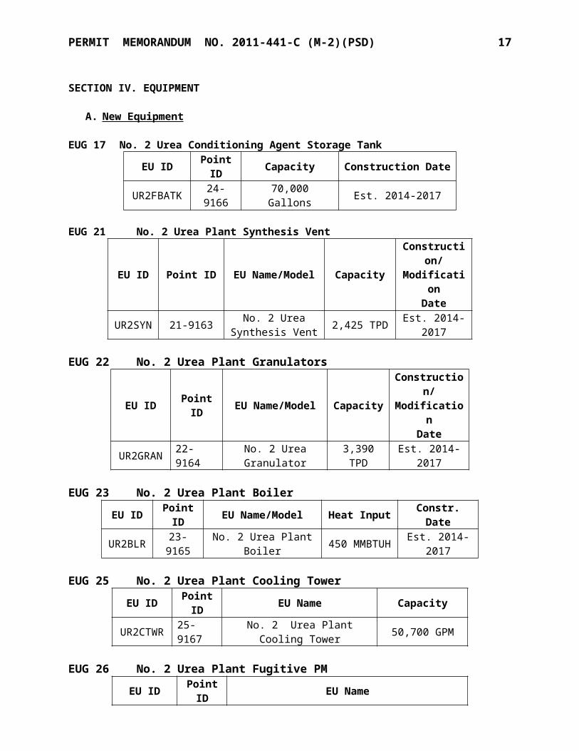
EUG 17 No. 2 Urea Conditioning Agent Storage TankEU ID Point ID Capacity Construction Date
UR2FBATK 24-9166 70,000 Gallons Est. 2014-2017
EUG 21 No. 2 Urea Plant Synthesis Vent
EU ID Point ID EU Name/Model CapacityConstruction/ Modification
DateUR2SY
N 21-9163 No. 2 Urea Synthesis Vent 2,425 TPD Est. 2014-2017
EUG 22 No. 2 Urea Plant Granulators
EU ID Point ID EU Name/Model CapacityConstruction/ Modification
DateUR2GRA
N 22-9164 No. 2 Urea Granulator 3,390 TPD Est. 2014-2017
EUG 23 No. 2 Urea Plant BoilerEU ID Point ID EU Name/Model Heat Input Constr. Date
UR2BLR 23-9165 No. 2 Urea Plant Boiler 450 MMBTUH Est. 2014-2017
EUG 25 No. 2 Urea Plant Cooling TowerEU ID Point ID EU Name Capacity
UR2CTWR 25-9167 No. 2 Urea Plant Cooling Tower 50,700 GPM
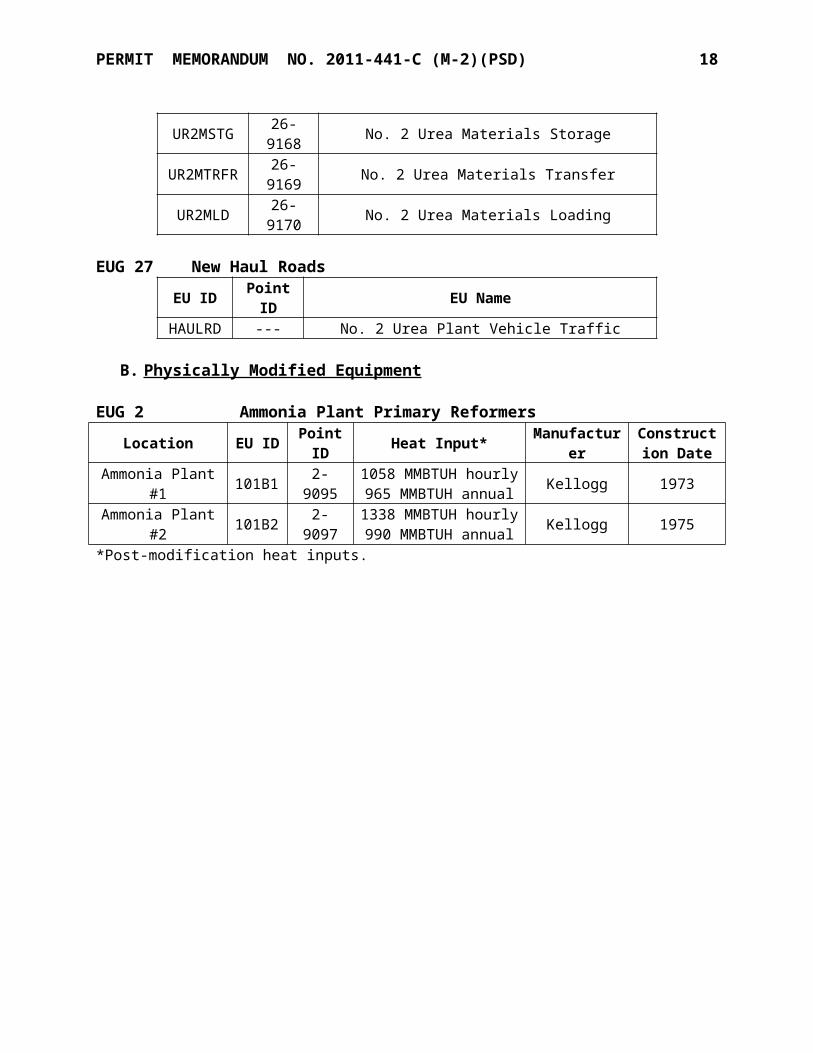
EUG 26 No. 2 Urea Plant Fugitive PMEU ID Point ID EU Name
UR2MSTG 26-9168 No. 2 Urea Materials StorageUR2MTRFR 26-9169 No. 2 Urea Materials Transfer
UR2MLD 26-9170 No. 2 Urea Materials Loading
EUG 27 New Haul RoadsEU ID Point ID EU Name
HAULRD --- No. 2 Urea Plant Vehicle Traffic
B. Physically Modified Equipment
EUG 2 Ammonia Plant Primary Reformers
Location EU ID Point ID Heat Input* Manufacture
rConstruction
Date
Ammonia Plant #1 101B1 2-9095 1058 MMBTUH hourly965 MMBTUH annual Kellogg 1973
Ammonia Plant #2 101B2 2-9097 1338 MMBTUH hourly990 MMBTUH annual Kellogg 1975
*Post-modification heat inputs.
PERMIT MEMORANDUM NO. 2011-441-C (M-2)(PSD) 11
EUG 9 No. 2 Ammonia Plant Cooling Tower EU ID Point ID EU Name Capacity22014B 9-9159 No. 2 Ammonia Plant Cooling Tower 65,700 GPM
EUG 10 CO2 Stripping Towers
Location EU ID Point ID EU Name/Model Manufacturer Construction Date
Ammonia Plant #1 1102E1 10-9120 CO2 Stripping Tower 1 (PV30-1) Kellogg 1973
Ammonia Plant #2 1102E2 10-9121 CO2 Stripping Tower 2 (PV30-2) Kellogg 1975
C. Units with Increased Utilization
EUG 1 Plant-wide
This EUG is established to address requirements that apply to the entire plant, including open burning restrictions, visible emissions, fugitive dust control. The plant is requesting to operate under a state and federally enforceable plant-wide cap for methanol, which is classified as a haz-ardous air pollutant (HAP). The process condensate stripper, the primary source of methanol emissions from this type of plant, is refluxed to the process rather than vented to the atmosphere.
EUG 7 No. 1 Urea Plant Synthesis Vents
EU ID Point ID EU Name/Model Manufacturer Capacity
Construction/ Modification
DateHIC135 7-9111 High Pressure Vent Foster Wheeler 1,550 TPD 1980 / 2007D119 7-9110 Low Pressure Vent Foster Wheeler 1,550 TPD 1980 / 2007
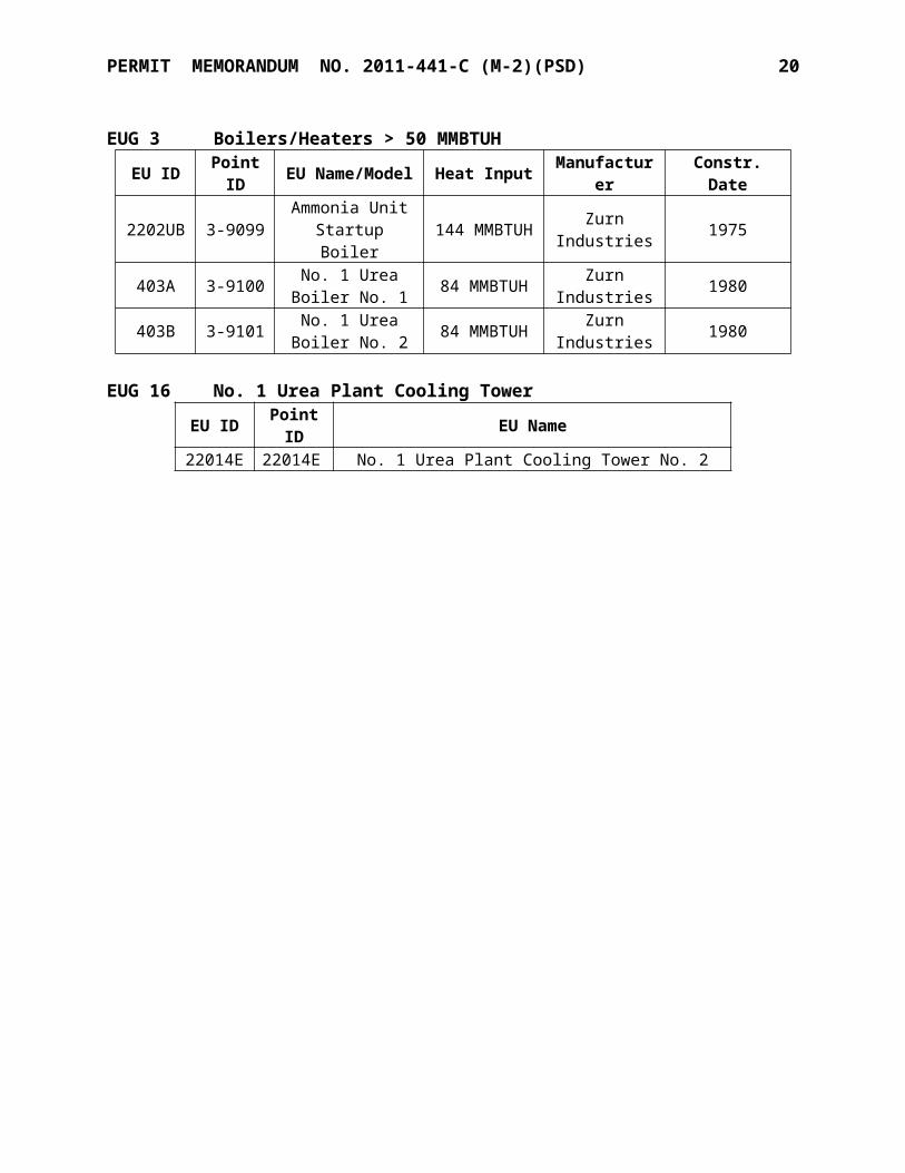
EUG 3 Boilers/Heaters > 50 MMBTUHEU ID Point ID EU Name/Model Heat Input Manufacturer Constr. Date
2202UB 3-9099 Ammonia Unit Startup Boiler 144 MMBTUH Zurn Industries 1975
403A 3-9100 No. 1 Urea Boiler No. 1 84 MMBTUH Zurn Industries 1980
403B 3-9101 No. 1 Urea Boiler No. 2 84 MMBTUH Zurn Industries 1980
EUG 16 No. 1 Urea Plant Cooling TowerEU ID Point ID EU Name22014E 22014E No. 1 Urea Plant Cooling Tower No. 2
PERMIT MEMORANDUM NO. 2011-441-C (M-2)(PSD) 12
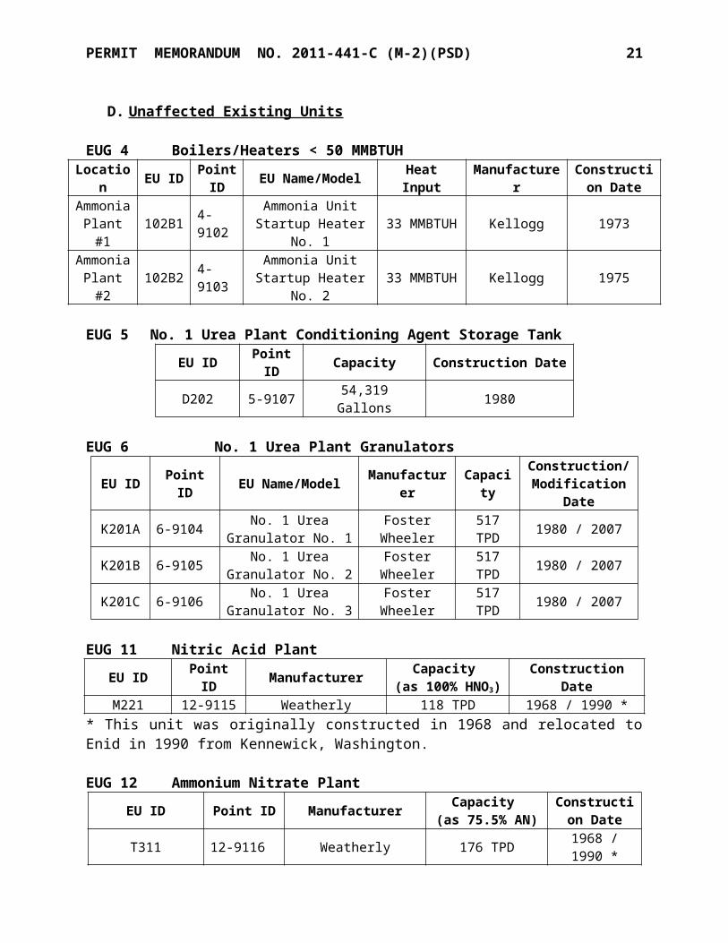
D. Unaffected Existing Units
EUG 4 Boilers/Heaters < 50 MMBTUH
Location EU ID Point ID EU Name/Model Heat Input Manufacturer Construction
DateAmmonia Plant #1 102B1 4-9102 Ammonia Unit Startup
Heater No. 1 33 MMBTUH Kellogg 1973
Ammonia Plant #2 102B2 4-9103 Ammonia Unit Startup
Heater No. 2 33 MMBTUH Kellogg 1975
EUG 5 No. 1 Urea Plant Conditioning Agent Storage TankEU ID Point ID Capacity Construction DateD202 5-9107 54,319 Gallons 1980
EUG 6 No. 1 Urea Plant Granulators
EU ID Point ID EU Name/Model Manufacturer CapacityConstruction/ Modification
Date
K201A 6-9104 No. 1 Urea Granulator No. 1 Foster Wheeler 517 TPD 1980 / 2007
K201B 6-9105 No. 1 Urea Granulator No. 2 Foster Wheeler 517 TPD 1980 / 2007
K201C 6-9106 No. 1 Urea Granulator No. 3 Foster Wheeler 517 TPD 1980 / 2007
EUG 11 Nitric Acid PlantEU ID Point ID Manufacturer Capacity
(as 100% HNO3)Construction Date
M221 12-9115 Weatherly 118 TPD 1968 / 1990 ** This unit was originally constructed in 1968 and relocated to Enid in 1990 from Kennewick, Washington.
EUG 12 Ammonium Nitrate Plant
EU ID Point ID Manufacturer Capacity (as 75.5% AN)
Construction Date
T311 12-9116 Weatherly 176 TPD 1968 / 1990 ** This unit was constructed in a different location and relocated to Enid in 1990.
EUG 13 FlareEU ID Point ID Heat Input * Construction Date222OU 13-9118 1,350 SCFH 1993
*Heat input refers to natural gas and/or purge gas to maintain flare pilot.
EUG 14 FugitivesLocation EU ID Point ID EU Name
Ammonia Plants AMH 14-9119 Ammonia Plant Material Handling –Materials LoadingNo. 1 Urea Plant UMH 14-9120 No. 1 Urea Plant Material Handling/Loading Fugitives

PERMIT MEMORANDUM NO. 2011-441-C (M-2)(PSD) 13
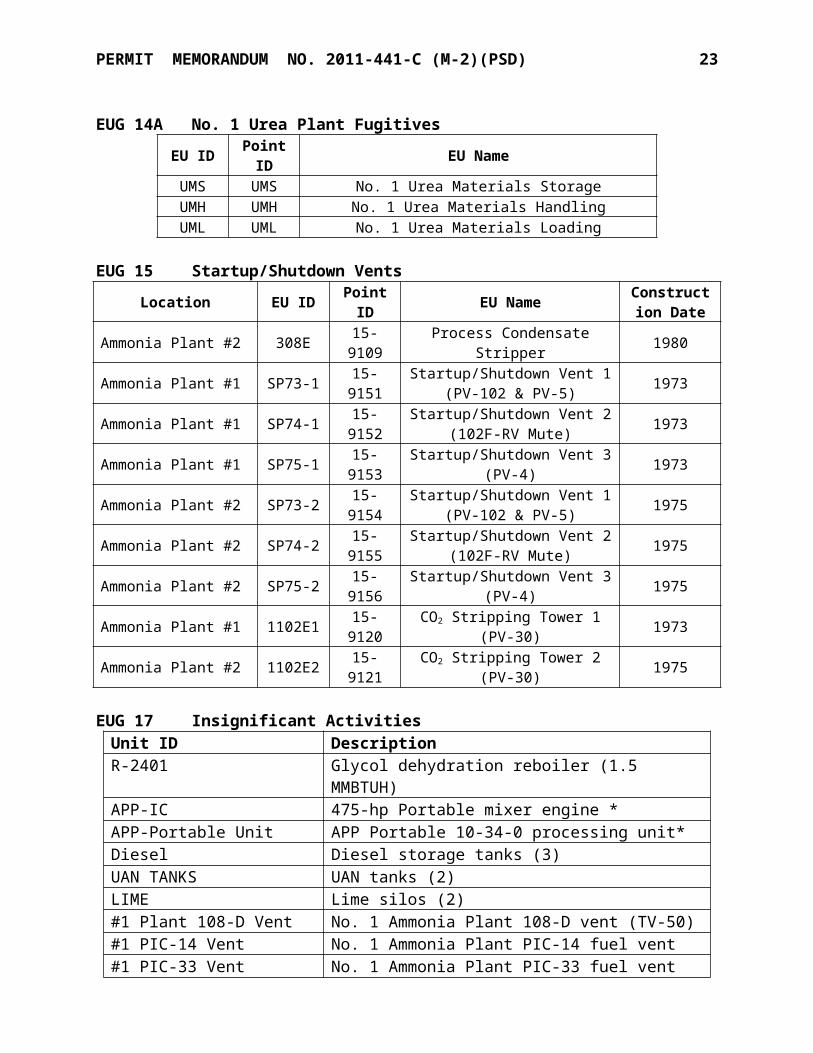
EUG 14A No. 1 Urea Plant FugitivesEU ID Point ID EU NameUMS UMS No. 1 Urea Materials StorageUMH UMH No. 1 Urea Materials HandlingUML UML No. 1 Urea Materials Loading
EUG 15 Startup/Shutdown Vents
Location EU ID Point ID EU Name Construction Date
Ammonia Plant #2 308E 15-9109 Process Condensate Stripper 1980
Ammonia Plant #1 SP73-1 15-9151 Startup/Shutdown Vent 1 (PV-102 & PV-5) 1973
Ammonia Plant #1 SP74-1 15-9152 Startup/Shutdown Vent 2 (102F-RV Mute) 1973
Ammonia Plant #1 SP75-1 15-9153 Startup/Shutdown Vent 3 (PV-4) 1973
Ammonia Plant #2 SP73-2 15-9154 Startup/Shutdown Vent 1 (PV-102 & PV-5) 1975
Ammonia Plant #2 SP74-2 15-9155 Startup/Shutdown Vent 2 (102F-RV Mute) 1975
Ammonia Plant #2 SP75-2 15-9156 Startup/Shutdown Vent 3 (PV-4) 1975Ammonia Plant #1 1102E1 15-9120 CO2 Stripping Tower 1 (PV-30) 1973Ammonia Plant #2 1102E2 15-9121 CO2 Stripping Tower 2 (PV-30) 1975
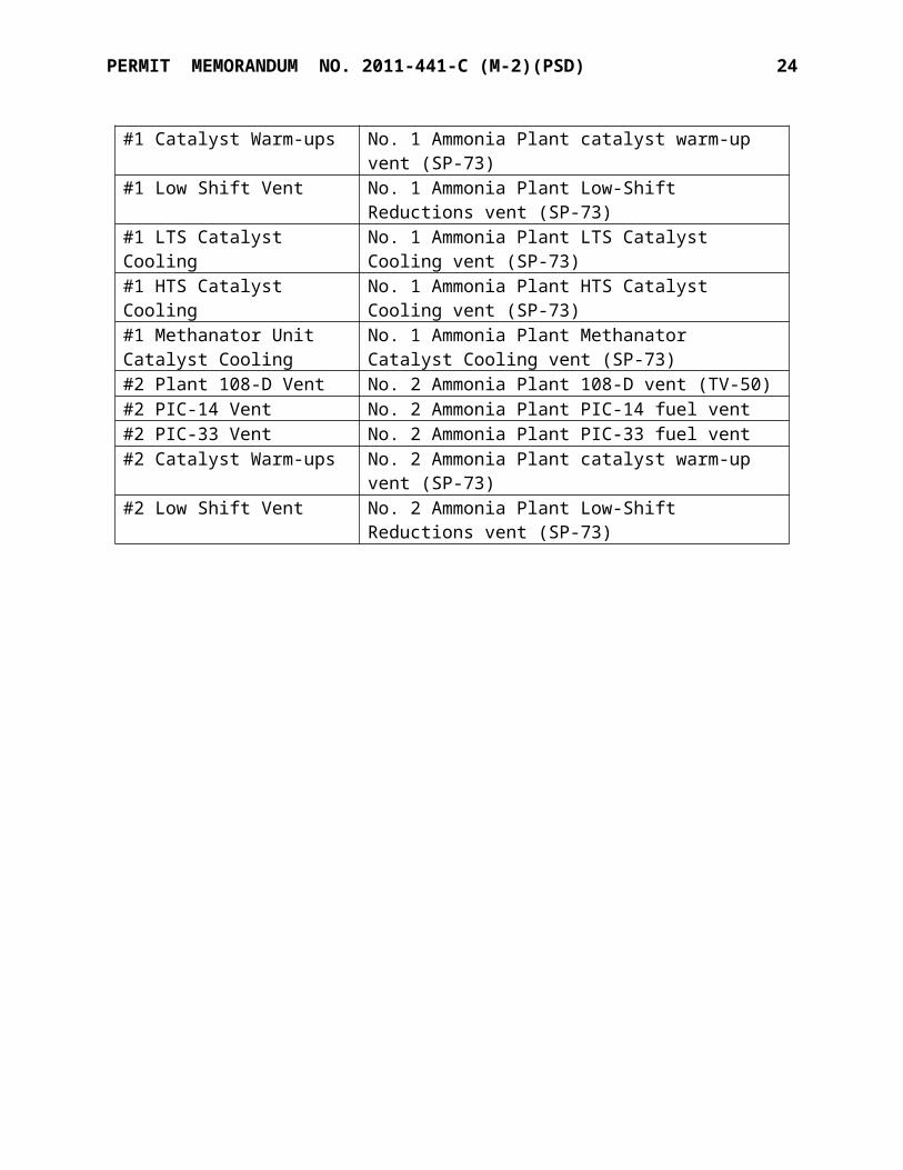
EUG 17 Insignificant ActivitiesUnit ID DescriptionR-2401 Glycol dehydration reboiler (1.5 MMBTUH)APP-IC 475-hp Portable mixer engine *APP-Portable Unit APP Portable 10-34-0 processing unit*Diesel Diesel storage tanks (3)UAN TANKS UAN tanks (2)LIME Lime silos (2)#1 Plant 108-D Vent No. 1 Ammonia Plant 108-D vent (TV-50)#1 PIC-14 Vent No. 1 Ammonia Plant PIC-14 fuel vent#1 PIC-33 Vent No. 1 Ammonia Plant PIC-33 fuel vent#1 Catalyst Warm-ups No. 1 Ammonia Plant catalyst warm-up vent (SP-73)#1 Low Shift Vent No. 1 Ammonia Plant Low-Shift Reductions vent (SP-73)#1 LTS Catalyst Cooling No. 1 Ammonia Plant LTS Catalyst Cooling vent (SP-73)#1 HTS Catalyst Cooling No. 1 Ammonia Plant HTS Catalyst Cooling vent (SP-73)#1 Methanator Unit Catalyst Cooling
No. 1 Ammonia Plant Methanator Catalyst Cooling vent (SP-73)
#2 Plant 108-D Vent No. 2 Ammonia Plant 108-D vent (TV-50)#2 PIC-14 Vent No. 2 Ammonia Plant PIC-14 fuel vent#2 PIC-33 Vent No. 2 Ammonia Plant PIC-33 fuel vent#2 Catalyst Warm-ups No. 2 Ammonia Plant catalyst warm-up vent (SP-73)#2 Low Shift Vent No. 2 Ammonia Plant Low-Shift Reductions vent (SP-73)
PERMIT MEMORANDUM NO. 2011-441-C (M-2)(PSD) 14
Unit ID Description#2 LTS Catalyst Cooling No. 2 Ammonia Plant LTS Catalyst Cooling vent (SP-
73)#2 HTS Catalyst Cooling No. 2 Ammonia Plant HTS Catalyst Cooling vent (SP-
73)#2 Methanator Unit Catalyst Cooling
No. 2 Ammonia Plant Methanator Catalyst Cooling vent (SP-73)
Lab Vents Laboratory fume hoods and ventsUR2FBATK No. 2 Urea Plant conditioning agent tank
* Equipment owned, operated, and maintained by a contractor.
EUG 18. Emergency Engines Subject to NSPS Subpart JJJJ
Point ID# Capacity(hp) Make/Model Installed Date
GEN2 147 Generac 6.8GN 2010GEN3 40 Olympian G25LTA 2011
EUG 19. Diesel Engines Subject to NESHAP Subpart ZZZZ
Point ID# Capacity(hp) Make/Model Serial Number Installed Date
GEN 460 Cummins KT-1150-G 100P1432 1976PUMP 145 Clarke VMFPT6HT 91B-02093 2002
EUG 20. Gasoline TankUnit ID Point EU Description Capacity Construction DateGasoline Gasoline Vehicle gasoline tank 1,128 gal >2003
SECTION V. EMISSIONS
Emissions calculations are shown for the new units and physically-modified units. In determining PSD applicability, the facility used the option of determining Projected Actual Emissions (PAE) from each modified unit to be the Potential-to-Emit from each unit. Potential emissions from each emissions unit have been calculated using the particular configuration that results in the maximum emissions from that unit on a pollutant-by-pollutant basis. This approach allows for permit conditions that reflect the PTE for the full range of potential operational configurations, which are in turn based on the fundamental business purpose of the source.
Emission factors are derived from several sources including AP-42, other published emission estimation methodologies, stack tests, laboratory data, permitted limits, mass balance equations, and process knowledge. As indicated, some factors have been adjusted by a safety factor to account for process variability.

PERMIT MEMORANDUM NO. 2011-441-C (M-2)(PSD) 15
KNC quantified emissions of hazardous air pollutants (HAPs) from processes facility-wide. For the combustion processes, emission factors from AP-42 (7/98), Section 1.4 and Section 1.11 and from other published information are used as a means of estimating emissions, some of which were derived from limited test data. For HAP estimates from non-combustion processes, methodology is discussed in this section for individual emission unit groups. Ammonia emissions are no longer shown due to the revocation of OAC 252:100-41.
A. New Units
EUG 17: No. 2 Urea Plant Conditioning Agent Storage Tank
VOC / formaldehyde / methanol emissions from the storage tank were based on a mass balance (since the tank will be maintained at approximately 150oF, no breathing losses were calculated). An annual maximum throughput of 1,123,000 gallons, molecular weight of 30, and vapor pressure of 0.33 psia were used.
Vapor Pressure, psia Throughput, gallons Molecular Weight VOC Emissions, TPY
0.33 1,123,000 30 0.14
EUG 21: No. 2 Urea Plant Synthesis Vent
The new No. 2 Urea Plant has a design capacity of 2,425 TPD, with a maximum short-term production rate of 2,546 TPD (106.1 TPH). PM10 / PM2.5 emissions are based on vendor guarantees, while CO emissions are based on June 2006 analytical testing (where sampling of the CO content in the CO2 stream sent to urea plants) data plus a 300% safety factor.
Unit Throughput,
TPHPollutant Emission Factor
Emissions
lb/hr TPY
106.1 PM10 / PM2.5 0.046 lb/hr 0.05 0.20CO 0.029 lb/ton 3.08 12.83
Point ID EmissionUnit
PM10 / PM2.5 SO2 NOx VOC COlb/hr TPY lb/hr TPY lb/hr TPY lb/hr TPY lb/hr TPY
21-9163 No. 2 Urea Plant Vent 0.05 0.20 -- -- -- -- -- -- 3.08 12.83
EUG 22: No. 2 Urea Plant Granulator
The new No. 2 Urea Plant granulator will have a design capacity of 3,390 TPD (141.25 TPH). The listed PM emission factor, 0.043 lb/ton, was derived from vendor guarantees for PM emissions of 5 mg / dry m3. Controlled formaldehyde emissions were taken from EPA’s “Locating and Estimating Air Emissions from Sources of Formaldehyde” (March 1991). Methanol emissions were based on 0.1% in the granulation additive, annual usage of 1,123,000 gallons, and 11.0 lb/gal density. VOC is the sum of methanol plus formaldehyde.

PERMIT MEMORANDUM NO. 2011-441-C (M-2)(PSD) 16
Unit Throughput,
TPHPollutant Emission Factor
Emissions
lb/hr TPY
141.25
PM10 / PM2.5 0.043 lb/ton 6.04 26.45VOC 0.029 lb/ton 2.39 8.44
Formaldehyde 0.0054 lb/ton 0.76 3.34Methanol Mass balance 1.41 4.34
Point ID EmissionUnit
PM10 / PM2.5 SO2 NOx VOC COlb/hr TPY lb/hr TPY lb/hr TPY lb/hr TPY lb/hr TPY
22-9164No. 2 Urea
Plant Granulator
6.04 26.45 -- -- -- -- 2.39 8.44 -- --
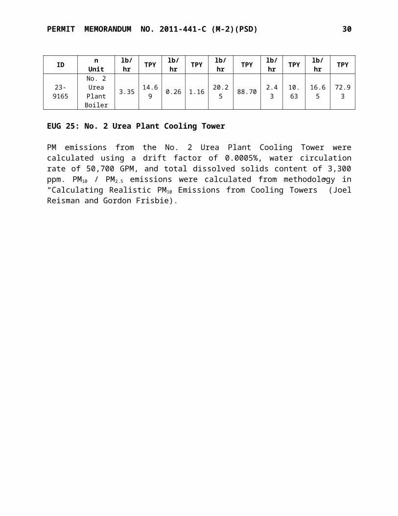
EUG 23: No. 2 Urea Plant Boiler
Emissions from the new boiler were based on a unit capacity of 450 MMBTUH. NOx and CO emission are taken from manufacturer data, but a 25% safety factor was added to NOx emissions. SO2, VOC, and PM emissions were based on AP-42 (1/95), Section 1.4. GHG emission factors are based on 40 CFR 98, Subpart C for natural gas combustion.
Unit Capacity PollutantEmission Factor,
lb/MMBTU
Emissions
lb/hr TPY
450 MMBTUH
CO 0.037 16.65 72.93NOx 0.045 20.25 88.70SO2 0.0006 0.26 1.16
VOC 0.0055 2.43 10.63PM10 / PM2.5 0.0076 3.35 14.69
GHG 117 52,652 230,614
Point ID EmissionUnit
PM10 / PM2.5 SO2 NOx VOC COlb/hr TPY lb/hr TPY lb/hr TPY lb/hr TPY lb/hr TPY
23-9165No. 2 Urea
Plant Boiler
3.35 14.69 0.26 1.16 20.25 88.70 2.43 10.63 16.65 72.93
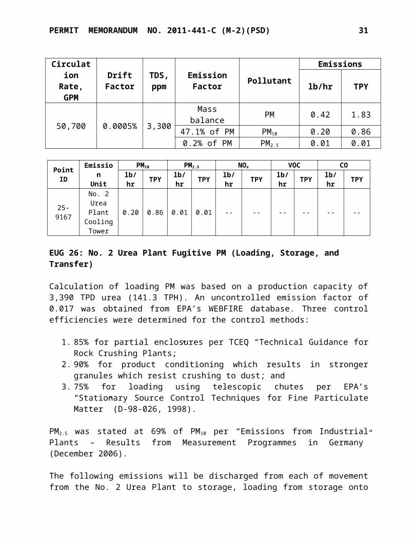
EUG 25: No. 2 Urea Plant Cooling Tower
PM emissions from the No. 2 Urea Plant Cooling Tower were calculated using a drift factor of 0.0005%, water circulation rate of 50,700 GPM, and total dissolved solids content of 3,300 ppm. PM10 / PM2.5 emissions were calculated from methodology in “Calculating Realistic PM10
Emissions from Cooling Towers” (Joel Reisman and Gordon Frisbie).
PERMIT MEMORANDUM NO. 2011-441-C (M-2)(PSD) 17
Circulation Rate, GPM
Drift Factor
TDS, ppm
Emission Factor Pollutant Emissions
lb/hr TPY
50,700 0.0005% 3,300Mass balance PM 0.42 1.8347.1% of PM PM10 0.20 0.860.2% of PM PM2.5 0.01 0.01
Point ID
EmissionUnit
PM10 PM2.5 NOx VOC COlb/hr TPY lb/hr TPY lb/hr TPY lb/hr TPY lb/hr TPY
25-9167
No. 2 Urea Plant
Cooling Tower
0.20 0.86 0.01 0.01 -- -- -- -- -- --
EUG 26: No. 2 Urea Plant Fugitive PM (Loading, Storage, and Transfer)
Calculation of loading PM was based on a production capacity of 3,390 TPD urea (141.3 TPH). An uncontrolled emission factor of 0.017 was obtained from EPA’s WEBFIRE database. Three control efficiencies were determined for the control methods:
1. 85% for partial enclosures per TCEQ “Technical Guidance for Rock Crushing Plants;”2. 90% for product conditioning which results in stronger granules which resist crushing to
dust; and3. 75% for loading using telescopic chutes per EPA’s “Stationary Source Control
Techniques for Fine Particulate Matter” (D-98-026, 1998).
PM2.5 was stated at 69% of PM10 per “Emissions from Industrial Plants – Results from Measurement Programmes in Germany” (December 2006).
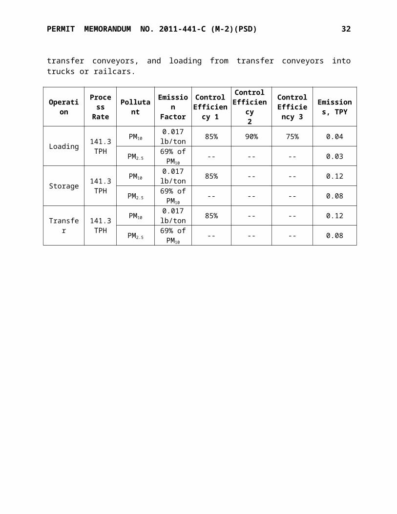
The following emissions will be discharged from each of movement from the No. 2 Urea Plant to storage, loading from storage onto transfer conveyors, and loading from transfer conveyors into trucks or railcars.
Operation Process Rate Pollutant Emission
Factor
Control Efficiency
1
Control Efficiency
2
Control Efficiency
3
Emissions, TPY
Loading 141.3 TPH
PM100.017 lb/ton 85% 90% 75% 0.04
PM2.569% of PM10
-- -- -- 0.03
Storage 141.3 TPH
PM100.017 lb/ton 85% -- -- 0.12
PM2.569% of PM10
-- -- -- 0.08
Transfer 141.3 TPH
PM100.017 lb/ton 85% -- -- 0.12
PM2.569% of PM10
-- -- -- 0.08
PERMIT MEMORANDUM NO. 2011-441-C (M-2)(PSD) 18
EUG 27: New Haul Roads
Fugitive dust emissions were calculated using the method of AP-42 (1/2011), Section 13.2.1:
EF (lb/VMT) = k * (sl)0.91 * W1.02 * (1 – p / 4N) * (1 – CE)
Where k = 0.0022 for PM10 and 0.00054 for PM2.5
sl = silt loading, 0.6 g/m2
W = average vehicle weight, 27 tonsp = number of days in a year with at least 0.01 inch rain, default = 80N = number of days in a year, 365CE = control efficiency, 82.9% for water flushing and sweeping
The facility anticipates loading 27 tons per truck:- 109 trucks per day hauling urea 0.303 mile each way (66 miles/day, 24,100 miles/yr)- 40 trucks per day hauling DEF 0.18 mile each way (29 miles/day, 10,500 miles/yr)
EPA guidance, “Control of Open Fugitive Dust Sources” (EPA-450/3-88-008), Table 2-4, lists a control efficiency for “Water flushing followed by sweeping” as “96% - 0.263 * V,” where V is the number of vehicles which traverse a road following the control measure, here shown as 100, or approximately the anticipated number of vehicles per day.
Based on the emission calculations for the road segments and summing all segments, PM10
emissions will be 0.377 TPY and PM2.5 emissions will be 0.092 TPY.
B. Physically Modified Equipment
EUG 1: Plant-wide Emissions
The process CO2 generated in the No. 1 Ammonia Plant and No. 2 Ammonia Plant can be emitted from vents located in the No. 1 Ammonia Plant, No. 2 Ammonia Plant, No. 1 Urea Plant, No. 2 Urea Plant and other locations/vents throughout the facility. The total CO2 generation is based on ammonia production capacity and the 40 CFR 98, Subpart G calculation methodology. The potential annual process CO2 emissions are based on a maximum expected process CO2
emission rate of 1.26 tons of CO2 per ton of ammonia generated.
Unit FeedstockMMscf/yr Carbon Content
Potential Process CO2
GenerationTPY
CO2 Potential to Emit1
TPY
No. 1 Ammonia Plant 13,297 0.74 781,829 --
No. 2 Ammonia Plant 14,861 0.74 873,809 --
TOTALS 1,655,639 1,260,0001 – Based on emission rate of 1.26 tons CO2 / ton ammonia where the potential to emit is limited by permit condition.

PERMIT MEMORANDUM NO. 2011-441-C (M-2)(PSD) 19
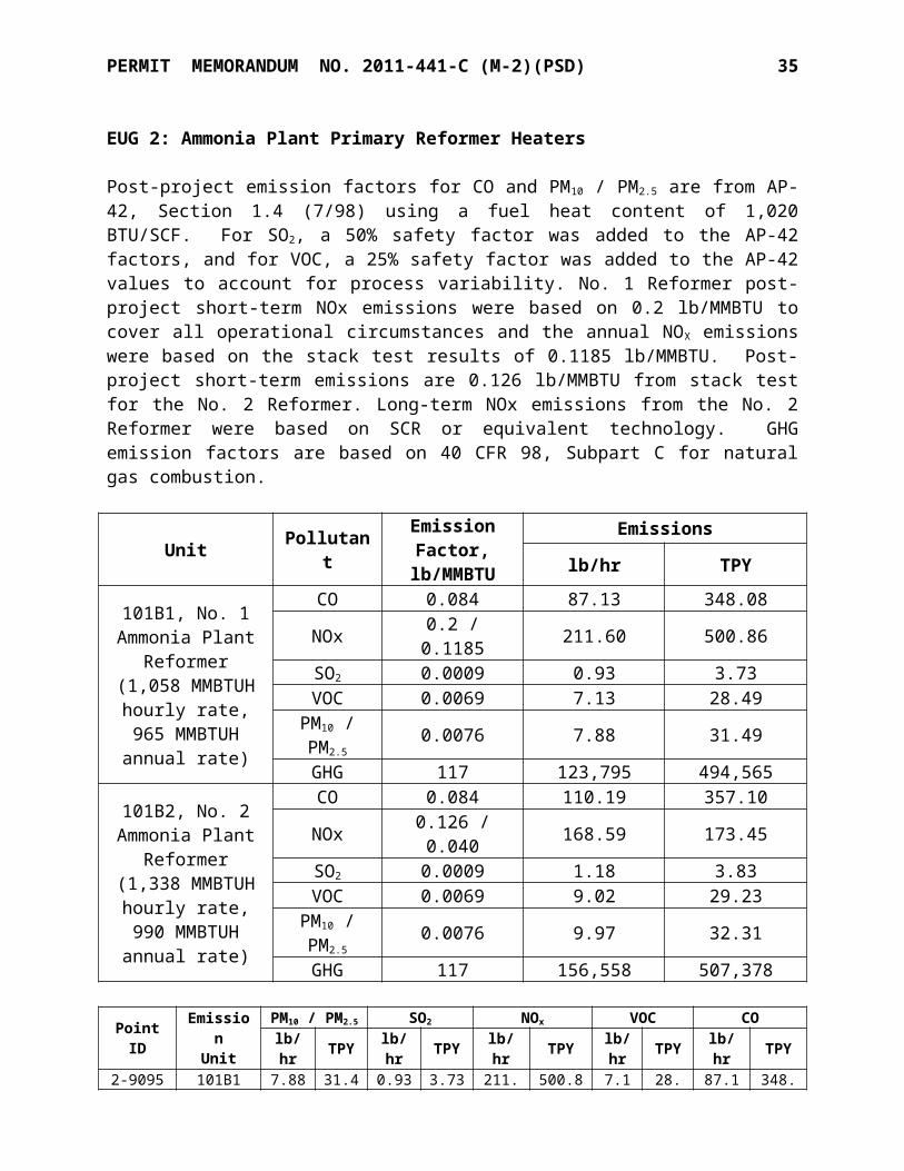
EUG 2: Ammonia Plant Primary Reformer Heaters
Post-project emission factors for CO and PM10 / PM2.5 are from AP-42, Section 1.4 (7/98) using a fuel heat content of 1,020 BTU/SCF. For SO2, a 50% safety factor was added to the AP-42 factors, and for VOC, a 25% safety factor was added to the AP-42 values to account for process variability. No. 1 Reformer post-project short-term NOx emissions were based on 0.2 lb/MMBTU to cover all operational circumstances and the annual NOX emissions were based on the stack test results of 0.1185 lb/MMBTU. Post-project short-term emissions are 0.126 lb/MMBTU from stack test for the No. 2 Reformer. Long-term NOx emissions from the No. 2 Reformer were based on SCR or equivalent technology. GHG emission factors are based on 40 CFR 98, Subpart C for natural gas combustion.
Unit PollutantEmission Factor,
lb/MMBTU
Emissions
lb/hr TPY101B1, No. 1
Ammonia Plant Reformer (1,058
MMBTUH hourly rate, 965 MMBTUH
annual rate)
CO 0.084 87.13 348.08NOx 0.2 / 0.1185 211.60 500.86SO2 0.0009 0.93 3.73
VOC 0.0069 7.13 28.49PM10 / PM2.5 0.0076 7.88 31.49
GHG 117 123,795 494,565101B2, No. 2
Ammonia Plant Reformer (1,338
MMBTUH hourly rate, 990 MMBTUH
annual rate)
CO 0.084 110.19 357.10NOx 0.126 / 0.040 168.59 173.45SO2 0.0009 1.18 3.83
VOC 0.0069 9.02 29.23PM10 / PM2.5 0.0076 9.97 32.31
GHG 117 156,558 507,378
Point ID EmissionUnit
PM10 / PM2.5 SO2 NOx VOC COlb/hr TPY lb/hr TPY lb/hr TPY lb/hr TPY lb/hr TPY
2-9095 (No. 1
Reformer)101B1 7.88 31.49 0.93 3.73 211.6
0 500.86 7.13 28.49 87.13 348.08
2-9097 (No. 2
Reformer)101B2 9.97 32.31 1.18 3.83 168.5
9 173.45 9.02 29.23 110.19 357.10
TOTALS 17.85 63.80 2.11 7.56 380.19 674.31 16.15 57.72 197.3
2 705.18
EUG 9: No. 2 Ammonia Plant Cooling Tower
PM emissions from the No. 2 Ammonia Plant Cooling Tower added cell were calculated using a drift factor of 0.0005%, water circulation rate of 12,700 GPM, and total dissolved solids content of 3,300 ppm. PM10 / PM2.5 emissions were calculated from methodology in “Calculating Realistic PM10 Emissions from Cooling Towers” (Joel Reisman and Gordon Frisbie). Emissions from the existing cooling tower cells were based on a circulation rate of 53,000 GPM and a drift factor of 0.001% using the Reisman and Frisbie methodology.
PERMIT MEMORANDUM NO. 2011-441-C (M-2)(PSD) 20
Circulation Rate, GPM Drift Factor TDS,
ppmEmission
Factor Pollutant Emissionslb/hr TPY
53,000 0.001% 3,300Mass balance PM 0.88 3.8347.1% of PM PM10 0.41 1.800.2% of PM PM2.5 0.01 0.01
12,700 0.0005% 3,300Mass balance PM 0.10 0.4647.1% of PM PM10 0.05 0.220.2% of PM PM2.5 0.001 0.005
65,700 3,300Mass balance PM 0.98 4.2947.1% of PM PM10 0.46 2.020.2% of PM PM2.5 0.01 0.01
Point ID
EmissionUnit
PM10 PM2.5 NOx VOC COlb/hr TPY lb/hr TPY lb/hr TPY lb/hr TPY lb/hr TPY
9-9159
No. 2 Ammonia
Plant Cooling Tower
0.46 2.02 0.002 0.009 -- -- -- -- -- --
EUG 10: CO2 Stripping Towers
Added emissions from these units are GHG only; CO emissions are not affected. Added GHG are part of the plant-wide emissions shown for EUG-1.
C. Units with Increased Utilization
EUG 7: No. 1 Urea Plant Synthesis Vents
CO emissions were derived from stack testing in 2006 as test results plus 300%, assuming equal CO between high-pressure and low-pressure vents. PM10 / PM2.5 emissions were based on AP-42 (7/93), assuming75% from the high pressure vent and 25% from the low-pressure vent. Hourly emissions assume a short-term production rate of 1,600 TPD, while annual emissions assume production of 1,550 TPD.
Unit Process Rate, TPH Pollutant
Emission Factor, lb/ton
Emissions
lb/hr TPYNo. 1 High-
Pressure Vent 66.7 PM10 / PM2.5 0.021 1.40 5.94CO 0.029 1.93 8.20
No. 1 Low-Pressure Vent 66.7 PM10 / PM2.5 0.007 0.47 1.98
CO 0.029 1.93 8.20
PERMIT MEMORANDUM NO. 2011-441-C (M-2)(PSD) 21
EUG 3 Boilers/Heaters > 50 MMBTUH
Post-project emission factors for CO, VOC, SO2, and PM10 / PM2.5 are from AP-42, Section 1.4 (7/98) using a fuel heat content of 1,020 BTU/SCF, and a 50% safety factor was added to the AP-42 factors to account for process variability. NOx emissions were based on the limitation of OAC 252:100-33 of 0.20 lb/MMBTU. GHG emission factors are based on 40 CFR 98, Subpart C for natural gas combustion.
Unit PollutantEmission Factor,
lb/MMBTU
Emissions
lb/hr TPY
403A, No. 1 Urea Plant Boiler
No. 1 (84 MMBTUH)
CO 0.126 10.38 45.45NOx 0.20 16.80 73.58SO2 0.0009 0.07 0.32
VOC 0.00825 0.68 2.98PM10 / PM2.5 0.0114 0.94 4.11
GHG 117 9,828 43,050
403B, No. 1 Urea Plant Boiler
No. 2 (84 MMBTUH)
CO 0.126 10.38 45.45NOx 0.20 16.80 73.58SO2 0.0009 0.07 0.32
VOC 0.00825 0.68 2.98PM10 / PM2.5 0.0114 0.94 4.11
GHG 117 9,828 43,050
Point ID
EmissionUnit
PM10 / PM2.5 SO2 NOx VOC CO GHGlb/hr TPY lb/hr TPY lb/hr TPY lb/hr TPY lb/hr TPY lb/hr TPY
403A No. 1 Urea Plant Boiler 1 0.94 4.11 0.07 0.32 16.80 73.58 0.68 2.98 10.38 45.45 9,828 43,050
403B No. 1 Urea Plant Boiler 2 0.94 4.11 0.07 0.32 16.80 73.58 0.68 2.98 10.38 45.45 9,828 43,050
TOTALS 1.88 8.22 0.14 0.64 33.60 147.16 1.36 5.96 20.76 90.90 19,656 86,100
D. Unaffected Existing Units
EUG 3 Boilers/Heaters > 50 MMBTUH
Emission factors for CO, PM10, SO2, and VOC are from AP-42, Section 1.4 (7/98), and a fuel heating content of 1,020 BTU/SCF. A 150% safety factor was applied to the AP-42 factors to account for process variability. The emission factor for NOx is based on OAC 252:100-33 limit of 0.2 lb/MMBTU. The annual emission rates for 2202UB are based on 4,380 hours per year operation.
Point ID EmissionUnit
PM10 / PM2.5 SO2 NOx VOC COlb/hr TPY lb/hr TPY lb/hr TPY lb/hr TPY lb/hr TPY
3-9099 2202UB 1.6 3.5 0.1 0.2 28.8 63.0 1.2 2.6 17.8 39.0

PERMIT MEMORANDUM NO. 2011-441-C (M-2)(PSD) 22
EUG 4 Boilers/Heaters < 50 MMBTUH
Emission factors for CO, NOx, PM10, SO2, and VOC are from AP-42, Section 1.4 (7/98), and a fuel heating content of 1,020 BTU/SCF. A 150% safety factor was applied to the AP-42 factors to account for process variability.
Point ID EmissionUnit
PM10 / PM2.5 SO2 NOx VOC COlb/hr TPY lb/hr TPY lb/hr TPY lb/hr TPY lb/hr TPY
4-9102 102B1 0.4 1.6 0.03 0.1 4.9 21.3 0.3 1.2 4.1 17.94-9103 102B2 0.4 1.6 0.03 0.1 4.9 21.3 0.3 1.2 4.1 17.9
TOTALS 0.8 3.2 0.06 0.2 9.8 42.6 0.6 2.4 8.1 35.8
EUG 5 No. 1 Urea Plant Conditioning Agent Storage Tank
Maximum emission estimates of formaldehyde from the No. 1 Urea Plant conditioning agent storage tank (EU-D202) are based on a maximum annual loading rate, maximum hourly loading rate, and upper-bound free formaldehyde concentration in the conditioning agent (30% by weight). The emission factor for formaldehyde was derived from the ideal gas law using the partial pressure of a 30% aqueous formaldehyde solution at a maximum anticipated storage temperature.
Point ID Tank No.Formaldehyde
Emissionslb/hr TPY
5-9107 D202 1.7 0.10
Methanol emissions from this source are included in EUG 6 as it was conservatively assumed that the methanol contained in the conditioning agent would all be emitted during the granulation process.
EUG 6 No. 1 Urea Plant Granulators
The emission factor for PM is the controlled factor derived from recent stack testing, 0.307 lb/ton from drum granulators, plus a 13% safety factor. It was assumed that PM is equal to PM10.
Formaldehyde factors are from an EPA document, “Locating and Estimating Air Emissions from Sources of Formaldehyde (Revised)”, dated March 1991. The EPA document provides a controlled emission factor of 0.0054 lb formaldehyde/ton urea.
Methanol emissions are present in the granulators from the methanol in the conditioning agent. Vendor specifications are “0.1% - 0.3%” methanol, but the concentrations are routinely less than 0.1%. Short-term emission rates were calculated using the maximum stated (0.3%) while annual emissions were estimated using a conservative 0.15%.
PERMIT MEMORANDUM NO. 2011-441-C (M-2)(PSD) 23
Point ID EmissionUnit
PM10 / PM2.5 Formaldehyde Methanollb/hr TPY lb/hr TPY lb/hr TPY
6-9104 No. 1 Urea Granulator 1 6.60 28.92 0.12 0.51 1.01 2.21
6-9105 No. 1 Urea Granulator 2 6.60 28.92 0.12 0.51 1.01 2.21
6-9106 No. 1 Urea Granulator 3 6.60 28.92 0.12 0.51 1.01 2.21
TOTALS 19.80 86.76 0.36 1.53 3.03 6.62
EUG 10 CO2 Stripping Towers
Based on process knowledge, a small amount of CO may be present in the CO2 stream vented from the CO2 stripper during startup, shutdown, or malfunction events. The emission factor for CO is derived from testing performed in June 2006 for the CO2 Stripping Tower #1 scaled up to the maximum CO2 production rate and a safety factor of 300% to account for process variability. Note that CO emissions are only vented from this source during startup, shutdown, or malfunction events; however, for PTE calculations, 8,760 hours/year of venting was assumed.
Point ID Emission Unit COlb/hr TPY
10-9120 CO2 Stripping Tower 1 5.8 25.410-9121 CO2 Stripping Tower 2 5.8 25.4TOTALS 11.6 50.8
This EUG also has the potential to emit methanol during periods of startup, shutdown, or malfunction of the ammonia plants. Startup/shutdown emissions are included in EUG 15.
EUG 11 Nitric Acid Plant
Potential emissions of NOx from this source are based on previously established permit limits from Permit No. 90-140-O. NOx emissions were calculated based on a permitted concentration of 79 ppmdv and a design exhaust flow rate of 8,817 SCFM. This unit is equipped with a non-selective catalytic reduction system (NSCR) to reduce NOx emissions.
Start-up and shutdown emissions have been based on 750 ppm, 3 hours per event, 50 events per year.
Point ID Emission Unit NOX
lb/hr TPY
12-9115 Nitric Acid Plant – Normal Operations 5.0 21.9Nitric Acid Plant – Start-up and Shutdown 47.5 3.6
TOTALS 47.5 25.5
PERMIT MEMORANDUM NO. 2011-441-C (M-2)(PSD) 24
EUG 12 UAN Plant
The emission factor for PM is a controlled factor from AP-42 Section 8.3. AP-42 provides a wide range of controlled factors for PM, which is based on the type of controls used at the UAN Plant. The maximum PM factor was adjusted to account for the type of controls used at the Enid Plant. It was assumed that PM is equal to PM10. A small amount of CO is present in the CO2
feed from the urea section of the UAN Plant. A mass balance equation was used to quantify CO emissions.
Point ID Emission Unit PM10 / PM2.5 COlb/hr TPY lb/hr TPY
12-9116 UAN Plant 2.6 11.0 0.1 0.5
EUG 13 Flare
The flare pilot consumes 1,350 SCF/hr natural gas and the flare combusts a maximum 60,000 lb/hr of ammonia. The flare is designed to meet a 98% destruction efficiency. For the combustion of natural gas and ammonia plant purge gas, the emission factors for CO and NOx
are from AP-42 Section 13.5 (dated 9/91, reformatted 1/95). VOC emissions were calculated using a mass balance and based on 98% destruction efficiency. The emission factor for SO 2 is from AP-42 Section 1.4 (dated 7/98). KNC estimated NOx emissions from ammonia flaring using emission estimating methodologies from the "Air Permit and Technical Guidance for Chemical Sources: Flares and Oxidizers", Texas Natural Resource Conservation Commission (TNRCC), Air Permits Division, October 2000 (RG-109 Draft).
Point ID
Emission Unit
SO2 NOx VOC CO
lb/hr TPY lb/hr TPY lb/hr TPY lb/hr TPY
13-9118 Flare 0.05 0.01 339.3 15.8 80.1 2.3 30.4 3.0
EUG 14 Plant Fugitives
The main source of particulate matter fugitive emissions at the plant consists of urea fugitives from granular urea storage, transfer, and loading (EU UMH). These operations should generate negligible PM10 due to the organic, non-brittle, sticky nature of the material. In addition, the plant adds a conditioning agent that further reduces dust formation.
Point ID Emission Unit PM PM10
lb/hr TPY lb/hr TPYUMH No. 1 Urea Handling/ Loading 1.68 2.38 -- --

PERMIT MEMORANDUM NO. 2011-441-C (M-2)(PSD) 25
EUG 14A No. 1 Urea Plant Fugitives
Fugitive emissions associated with the storage, handling, and loading of the urea product are considered negligible due to the characteristics of the material. Urea is a non-brittle, organic, and sticky material that is not likely to generate significant amounts of dust or particulate emissions during material handling. A sieve analysis of urea product showed no measurable PM10. Using the methods of AP-42 (1/95) for batch drop operations will greatly overstate emissions.
Point ID Emission Unit PM PM10
lb/hr TPY lb/hr TPYUMS No. 1 Urea Materials Storage 0.04 0.20 -- --UMH No. 1 Urea Materials Handling 0.35 0.25 -- --UML No. 1 Urea Materials Loading 7.04 5.14 -- --
TOTALS 7.41 5.49 -- --
EUG 15 Startup/Shutdown Vents
The ammonia plant startup and shutdown vents (EUs SP73-1 and SP73-2) have the potential to emit large quantities of CO for a short period of time from pressure control valves located within each plant. A total of 63 hours/year was assumed. Potential emission rates are based on process flow rates and stream composition data.
Potential methanol emissions from the CO2 stripping towers (EU 1102E1 and 1102E2) were estimated based on the data from the June 2006 test for the #1 CO2 stripping tower. The test results were scaled up to the maximum CO2 production rate. It was assumed that methanol emissions from the #2 CO2 stripping tower are equivalent to the #1 CO2 stripping tower. A total of 36 hours/year from each vent was assumed PTE calculation purposes. Note that the potential methanol emissions are estimates only and are not intended to be used as individual emission unit limits in the permit since methanol emissions have been included in the Plant-wide cap.
The Process Condensate Stripper (EU 308E) has the potential to emit methanol only during unanticipated, unforeseen emergencies. Typically, this source does not vent to the atmosphere due to the process condensate recycle system. Potential methanol emissions from EU 308E have been estimated based on the maximum anticipated condensate flow rate and maximum anticipated methanol content. For annual emissions it was conservatively estimated that the plant would experience 36 hours per year of unforeseen releases. During plant maintenance, process condensate may be routed to the zero discharge pond. From the zero discharge pond, the water is sent to the wastewater concentrator. During these events, the methanol in the condensate may be evaporated from the wastewater concentrator; however, methanol emissions have been accounted for under the plant-wide cap as if they were emitted from the vent rather than the wastewater concentrator.

PERMIT MEMORANDUM NO. 2011-441-C (M-2)(PSD) 26
Point ID Emission Unit CO Methanollb/hr TPY lb/hr TPY*
15-9151 Ammonia Plant 1 SU/SD Vent No.1 (PV-102 & PV-5) 10,962.8 345.3 -- --
15-9154 Ammonia Plant 2 SU/SD Vent No.1 (PV-102 & PV-5) 10,962.8 345.3 -- --
15-9120 CO2 Stripping Tower 1 (PV30-1) -- -- 35.8 0.615-9121 CO2 Stripping Tower 2 (PV30-2) -- -- 35.8 0.615-9109 Process Condensate Stripper (308E) -- -- 131.9 2.4TOTALS 21925.6 690.6 203.5 3.6
*Annual emissions of methanol have been included in the EUG-1 plant-wide cap, and any one source may emit up to 9.9 TPY so long as all sources combined emit less than 9.9 TPY.
Note that the potential methanol emissions are estimates only and are not intended to be used as individual emission unit limits in the permit since methanol emissions have been included in the plant-wide cap.
EUG 16 No. 1 Urea Plant Cooling Tower No. 2
PM10 emissions from No. 1 Urea Cooling Tower No. 2 were calculated based on a maximum water circulation rate of 12,000 GPM, total dissolved solids of 3,500 ppm by weight, and a drift factor of 0.002%.
Point ID Emission Unit PM10
lb/hr TPY22014E No. 1 Urea Plant Cooling Tower 0.42 1.84
EUG 17 Insignificant Activities
Emissions estimates from the portable fertilizer mixing unit, which is owned, operated, and maintained by a contractor, are based on 350 hours/year anticipated operation and manufacturer’s data.
Emission UnitPM10 SO2 NOx VOC CO
lb/hr TPY lb/hr TP
Y lb/hr TPY lb/hr TPY lb/hr TPY
Glycol dehydration reboiler 0.01 0.05 0.01 0.01 0.2 0.6 0.01 0.04 0.1 0.5475-hp Portable mixer engine 0.01 0.05 0.01 0.03 0.3 1.5 0.01 0.06 0.1 0.03
APP Portable 10-34-0 processing unit -- -- -- -- -- -- -- -- -- --
Diesel storage tanks (3) -- -- -- -- -- -- -- 0.1 -- --UAN tanks (2) -- -- -- -- -- -- -- -- -- --Lime silos (2) 0.2 0.7 -- -- -- -- -- -- -- --

PERMIT MEMORANDUM NO. 2011-441-C (M-2)(PSD) 27
Emission UnitPM10 SO2 NOx VOC CO
lb/hr TPY lb/hr TP
Y lb/hr TPY lb/hr TPY lb/hr TPY
No. 1 Ammonia Plant TV-50 vent -- -- -- -- -- -- 104.3 4.9 -- --
No. 1 Ammonia Plant PIC-14 fuel vent -- -- -- -- -- -- 10.4 0.6 -- --
No. 1 Ammonia Plant PIC-33 fuel vent -- -- -- -- -- -- 10.4 0.6 -- --
No. 1 Ammonia Plant catalyst warm-up vent (SP-73)
-- -- -- -- -- -- 104.3 1.9 -- --
No. 1 Ammonia Plant Low-Shift Reductions vent(SP-73)
-- -- -- -- -- -- 291.4 4.1 -- --
No. 1 Ammonia Plant LTS Catalyst Cooling vent (SP-73)
-- -- -- -- -- -- 208.7 0.4 -- --
No. 1 Ammonia Plant HTS Catalyst Cooling vent (SP-73)
-- -- -- -- -- -- 208.7 0.4 -- --
No. 1 Ammonia Plant Methanator Catalyst Cooling vent (SP-73)
-- -- -- -- -- -- 208.7 0.4 -- --
No. 2 Ammonia Plant TV-50 vent -- -- -- -- -- -- 104.3 4.9 -- --
No. 2 Ammonia Plant PIC-14 fuel vent -- -- -- -- -- -- 10.4 0.6 -- --
No. 2 Ammonia Plant PIC-33 fuel vent -- -- -- -- -- -- 10.4 0.6 -- --
No. 2 Ammonia Plant catalyst warm-up vent (SP-73)
-- -- -- -- -- -- 104.3 1.9 -- --
No. 2 Ammonia Plant Low-Shift Reductions vent (SP-73)
-- -- -- -- -- -- 291.4 4.1 -- --
No. 2 Ammonia Plant LTS Catalyst Cooling vent (SP-73)
-- -- -- -- -- -- 208.7 0.4 -- --
No. 2 Ammonia Plant HTS Catalyst Cooling vent (SP-73)
-- -- -- -- -- -- 208.7 0.4 -- --
No. 2 Ammonia Plant Methanator Catalyst Cooling vent (SP-73)
-- -- -- -- -- -- 208.7 0.4 -- --
Laboratory Vents -- -- -- -- -- -- -- <5 -- --No. 2 Urea Plant Conditioning Agent Tank -- -- -- -- -- -- -- 0.14
TOTALS 0.22 0.8 0.01 0.04 0.5 2.1 2293.8 26.7 0.2 0.53

PERMIT MEMORANDUM NO. 2011-441-C (M-2)(PSD) 28
EUG 18. Emergency Engines Subject to NSPS Subpart JJJJ
Emissions factors for NOx, CO, and VOC are NSPS Subpart JJJJ limits. Emissions of PM and SO2 are taken from AP-42 (7/00), Section 3.2. Since PM is from natural gas combustion, PM2.5 is assumed equal to PM. 500 hours per year operations were used.
Rated Horsepower Pollutant Emission Factor Emissions
lb/hr TPY
GEN2 : 147-hp (1.24
MMBTUH)
NOx 2.0 g/hp-hr 0.65 0.16CO 4.0 g/hp-hr 1.30 0.32
VOC 1.0 g/hp-hr 0.32 0.08SO2 0.0006 lb/MMBTU 0.01 0.01
PM10 / PM2.5 0.0194 lb/MMBTU 0.02 0.01
GEN3 :40-hp (0.38
MMBTUH)
NOx 10 g/hp-hr 0.88 0.22CO 387 g/hp-hr 34.13 8.53
VOC 0.0296 lb/MMBTU 0.01 0.01SO2 0.0006 lb/MMBTU 0.01 0.01
PM10 / PM2.5 0.0194 lb/MMBTU 0.01 0.01
EUG 19. Diesel Engines Subject to NESHAP Subpart ZZZZ
Estimates of emissions from the emergency generator and the fire water pump are based on 500 hours of operations per year, with emission factors from Table 3.3-1 of AP-42 (10/96).
Emission Unit PM10 SO2 NOx VOC COlb/hr TPY lb/hr TPY lb/hr TPY lb/hr TPY lb/hr TPY
GEN : 460-hp Generator 1.1 0.3 0.9 0.2 14.3 3.6 1.2 0.3 3.1 0.8
PUMP: 145-hp Fire Pump 0.3 0.1 0.3 0.1 4.5 1.1 0.4 0.1 1.0 0.2
TOTALS 1.4 0.4 1.2 0.3 18.8 4.7 1.6 0.4 4.1 1.0
EUG 20. Gasoline Tank
VOC emissions are based on an annual throughput of 6,430 gallons, vapor pressure of 6.6 psia, and molecular weight of 66.
NET EMISSIONS CHANGES
The initial step in the process of determining net emissions changes was summing the post-project potential emissions for each new unit, each modified unit, and each unit with increased utilization. These totals exceeded the PSD levels of significance for NOx, CO, VOC, PM2.5/PM10, and GHG (but not SO2), requiring determination of net emissions changes.

PERMIT MEMORANDUM NO. 2011-441-C (M-2)(PSD) 29
Net emissions changes for the project were calculated by using the post-project potential emissions for each new unit, each modified unit, and each unit with increased utilization compared to the Baseline Actual Emissions (BAE) for each. The Projected Actual Emissions (PAE) for each modified and increase-utilization unit were taken as PTE.
The BAE period for all pollutants other than NOx was the 24-month period from September 2010 to August 2012; for NOx, the BAE period was March 2009 to February 2011.
The only contemporaneous projects were a modification to the two primary reformers and a upgrade to the UAN plant. The reformer project is accounted for in the emissions changes of those two reformers, and the UAN DCS upgrade project (19 TPY NOx addition) has been accounted for as a contemporaneous change.
Pre-Project Baseline Actual Emissions from Affected Units
Unit CO TPY
NOx TPY
PM10
TPYPM2.5
TPYVOC TPY
SO2
TPYGHG TPY
No. 1 Ammonia Plant Primary
Reformer0.68 332.81 28.38 28.38 20.54 2.24 445,682
No. 2 Ammonia Plant Primary
Reformer31.61 411.80 26.17 26.17 18.94 2.07 410,922
Ammonia Plant Process CO2
Emissions-- -- -- -- -- -- 486,234
No. 1 Urea Plant Boiler No. 1 28.74 72.63 2.60 2.60 1.88 0.21 40,839
No. 1 Urea Plant Boiler No. 2 28.74 72.73 2.60 2.60 1.88 0.21 40,839
No. 1 Urea Plant Synthesis Vents 8.83 -- 4.26 4.26 -- -- --
No. 2 Ammonia Plant Cooling
Tower-- -- 1.59 0.01 -- -- --
TOTALS 98.60 889.97 65.60 64.02 43.24 4.73 1,424,516
PERMIT MEMORANDUM NO. 2011-441-C (M-2)(PSD) 30
Post-Project Potential Emissions
Unit CO TPY
NOx TPY
PM10
TPYPM2.5
TPYVOC TPY
SO2
TPY GHG TPY
No. 1 Ammonia Plant Primary Reformer 348.08 500.86 31.49 31.49 28.49 3.73 494,565
No. 2 Ammonia Plant Primary Reformer 357.10 173.45 32.31 32.31 29.23 3.83 507,378
Ammonia Plant Process CO2 Emissions -- -- -- -- -- -- 1,260,000
No. 1 Urea Plant Boiler No. 1 45.45 73.58 4.11 4.11 2.98 0.32 43,050
No. 1 Urea Plant Boiler No. 2 45.45 73.58 4.11 4.11 2.98 0.32 43,050
No. 1 Urea Plant HP Synthesis Vent 8.20 -- 5.94 -- -- -- --
No. 1 Urea Plant LP Synthesis Vent 8.20 -- 1.98 -- -- -- --
No. 2 Urea Plant Synthesis Vent 12.83 -- 0.20 0.20 -- -- --
No. 2 Urea Plant Granulator -- -- 26.45 26.45 8.44 -- --
No. 2 Urea Plant Boiler 72.93 88.70 14.69 14.69 10.63 1.16 230,626No. 2 Urea Plant Cooling Tower -- -- 0.86 0.01 -- -- --
No. 2 Ammonia Plant Added Cooling Tower -- -- 2.02 0.01 -- -- --
No. 2 Urea Plant Conditioning Agent
Tank-- -- -- -- 0.14 -- --
New Haul Roads -- -- 0.38 0.09 -- -- --No. 2 Urea Plant
Loading -- -- 0.04 0.03 -- -- --
No. 2 Urea Plant Storage -- -- 0.12 0.08 -- -- --No. 2 Urea Plant
Transfer -- -- 0.11 0.07 -- -- --
UAN Plant Upgrade Project
Contemporaneous Emission Change
(Permit No. 99-092-C (M-5))
-- 19 -- -- -- -- --
TOTALS 898.24 929.17 124.81 113.65 82.89 9.36 2,578,669PRE-PROJECT BAE 98.60 889.97 65.60 64.02 43.24 4.73 1,424,516
NET CHANGES 799.65 39.2 59.21 49.63 39.65 4.63 1,154,153PSD LEVELS OF SIGNIFICANCE 100 40 15 10 40 40 75,000
SUBJECT TO PSD? Yes No Yes Yes No No Yes
PERMIT MEMORANDUM NO. 2011-441-C (M-2)(PSD) 31
FACILITY-WIDE CRITERIA POLLUTANT EMISSION SUMMARY (PTE)
EUG Description PM10 / PM2.5 SO2 NOX VOC COlb/hr TPY lb/hr TPY lb/hr TPY lb/hr TPY lb/hr TPY
EUG 2A Ammonia Plant #1 7.88 31.49 0.93 3.73 211.60 500.86 7.13 28.49 87.13 348.08EUG 2B Ammonia Plant #2 9.97 32.31 1.18 3.83 168.59 173.45 9.02 29.23 110.19 357.10
EUG 3 Heaters/Boilers> 50 MMBTUH 3.48 11.72 0.24 0.84 62.40 210.16 2.56 8.56 38.56 129.90
EUG 4 Heaters/Boilers< 50 MMBTUH 0.8 3.2 0.06 0.2 9.8 42.6 0.6 2.4 8.2 35.8
EUG 5No. 1 Urea Conditioning Agent Storage Tank
-- -- -- -- -- -- 1.7 0.1 -- --
EUG 6 No. 1 Urea Granulators 19.80 86.76 -- -- -- -- 3.69 8.15 -- --
EUG 7 No. 1 Urea Synthesis Vents 1.87 7.92 -- -- -- -- -- -- 3.87 16.41
EUG 9 No. 2 Ammonia Cooling Tower 0.46 2.02 -- -- -- -- -- -- -- --
EUG 10 CO2 Stripping Towers -- -- -- -- -- -- -- -- 11.6 50.8
EUG 11 Nitric Acid Plant -- -- -- -- 47.4 25.5 -- -- -- --EUG 12 UAN Plant 2.6 11.0 -- -- -- -- -- -- 0.1 0.5EUG 13 Flare -- -- 0.05 0.01 339.3 15.8 80.1 2.3 30.4 3.0
EUG 14 No. 1 Urea Plant Fugitives -- -- -- -- -- -- -- -- -- --
EUG 14A No. 1 Urea Fugitives -- -- -- -- -- -- -- -- -- --
EUG 15 Start-up/Shutdown Vents -- -- -- -- -- -- 203.5 -- 21,92
5.6 690.6
EUG 16 No. 1 Urea Cooling Tower No. 2 0.42 1.84 -- -- -- -- -- -- -- --
EUG 17 Insignificant Activities 0.2 0.8 0.01 0.01 0.5 2.1 2293.8 26.84 0.2 0.6
EUG 18 Emergency Engines 0.03 0.02 0.02 0.02 1.53 0.38 0.33 0.1 35.43 8.85EUG 19 Diesel Engines 1.4 0.4 1.2 0.3 18.8 4.7 1.6 0.4 4.1 1.0EUG 20 Vehicle Fueling -- -- -- -- -- -- -- 0.14 -- --EUG 21 No. 2 Urea Plant 0.05 0.20 -- -- -- -- -- -- 3.08 12.83
EUG 22 No. 2 Urea Granulator 6.04 26.45 -- -- -- -- 2.39 8.44 -- --
EUG 23 No. 2 Urea Plant Boiler 3.35 14.69 0.26 1.16 20.25 88.70 2.43 10.63 16.65 72.93
EUG 25 No. 2 Urea Plant Cooling Tower 0.20 0.86 -- -- -- -- -- -- -- --
EUG 26No. 2 Urea Plant Loading, Transfer, Storage
0.17 0.26 -- -- -- -- -- -- -- --
EUG 27 No. 2 Urea Plant Haul Roads 0.20 0.38 -- -- -- -- -- -- -- --
TOTALS 58.92 232.32 3.95 10.10 880.17 1064.25 2608.85 125.78 22275.1 1728.4
PERMIT MEMORANDUM NO. 2011-441-C (M-2)(PSD) 32
FACILTY-WIDE HAP EMISSIONS SUMMARY (PTE)
EmissionUnit Group
Formaldehyde Methanol*
lb/hr TPY lb/hr TPYEUG 1 – Plant-wide -- -- -- *EUG 2A – Ammonia Reformers 0.07 0.3 -- --EUG 2B – Ammonia Reformers 0.07 0.3 -- --EUG 3 – Heaters > 50 MMBTUH 0.06 0.1 -- --EUG 4 – Heaters < 50 MMBTUH 0.006 0.02 -- --EUG 5 – No. 1 Urea Conditioning Agent Storage Tank 1.7 0.1 -- --EUG 6 – No. 1 Urea Plant Granulators 0.4 1.5 3.0 *EUG 15 – Start-up/Shutdown Vents -- -- 203.5 *EUG-22 – No. 2 Urea Plant Granulator 0.76 3.34 1.41 *EUG-17 – No. 2 Urea Conditioning Agent Storage Tank 1.7 0.14 * *EUG 23 – No. 2 Urea Plant Boiler 0.03 0.13 -- --TOTALS 4.8 5.93 207.9 9.9
* Methanol emissions are included in the plant-wide cap, which allows any one source to emit up to 9.9 TPY so long as all sources combined emit less than 9.9 TPY. The cap is addressed in the Specific Conditions for EUG 1.
POTENTIAL GREENHOUSE GAS EMISSIONS Activity CO2-Equivalent Emissions, TPYNo. 1 Ammonia Plant Reformer 494,565No. 2 Ammonia Plant Reformer 507,378No. 1 and No. 2 Ammonia Plant Process CO2 1,260,000#1 Nitric Acid Plant 1,142Ammonia Unit Start-up Boiler 36,898Urea Boiler No. 1 43,050Urea Boiler No. 2 43,050Ammonia Unit Start-up Heater No. 1 16,912Ammonia Unit Start-up Heater No. 2 16,912Diesel-fired Emergency Engines 172Gas-fired Emergency Engines 49No. 2 Urea Plant Boiler 230,626TOTALS 2,650,754*The emissions above were estimated using the methodologies under 40 CFR 98. The 1,655,639 tons per year is for unlimited production. The permit will limit the process CO2 emissions to 1,260,000 tons per year.

PERMIT MEMORANDUM NO. 2011-441-C (M-2)(PSD) 33
SECTION VI. BACT REVIEW
OAC 252:100-8-31 states that BACT “means an emissions limitation (including a visible emissions standard) based on the maximum degree of reduction for each regulated NSR pollutant which would be emitted from any proposed major stationary source or major modification which the Director, on a case-by-case basis, taking into account energy, environmental, and economic impacts or other costs, determines is achievable for such source or modification….” A BACT analysis is required to assess the appropriate level of control for each new or physically modified emissions unit for each pollutant that exceeds the applicable PSD Significant Emissions Rate (SER).
The U.S. EPA has stated its preference for a “top-down” approach for determining BACT and that is the methodology used for this permit review. After determining whether any New Source Performance Standard (NSPS) is applicable, the first step in this approach is to determine, for the emission unit in question, the available control technologies, including the most stringent control technology, for a similar or identical source or source category. If the proposed BACT is equivalent to the most stringent emission limit, no further analysis is necessary.
If the most stringent emission limit is not selected, further analyses are required. Once the most stringent emission control technology has been identified, its technical feasibility must be determined; this leads to the reason for the term “available” in Best Available Control Technology. A technology that is available and is applicable to the source under review is considered technically feasible. A control technology is considered available if it has reached the licensing and commercial sales stage of development. In general, a control option is considered applicable if it has been, or is soon to be, developed on the same or similar source type. If the control technology is feasible, that control is considered to be BACT unless economic, energy, or environmental impacts preclude its use. This process defines the “best” term in Best Available Control Technology. If any of the control technologies are technically infeasible for the emission unit in question, that control technology is eliminated from consideration.
The remaining control technologies are then ranked by effectiveness and evaluated based on energy, environmental, and economic impacts beginning with the most stringent remaining technology. If it can be shown that this level of control should not be selected based on energy, environmental, or economic impacts, then the next most stringent level of control is evaluated. This process continues until the BACT level under consideration cannot be eliminated by any energy, environmental, or economic concerns.
The following resources were utilized in the BACT analysis:
- EPA’s RACT/BACT/LAER (RBLC) Clearinghouse.
- Federal / state / local new source review permits, permit applications, and associated inspection and testing reports.
- Technical journals, newsletters, and reports, including the “Report of the Interagency Task Force on Carbon Capture and Storage” (August 2010).
- Information from air quality control technology suppliers.

PERMIT MEMORANDUM NO. 2011-441-C (M-2)(PSD) 34
- Engineering designs on related projects.
- “PSD and Title V Permitting Guidance for Greenhouse Gases” (EPA-457/B-11-001, March 2011).
- “New Source Review Workshop Manual” (Draft, October 1990).
The five basic steps of a top-down BACT review are summarized as follows:
Step 1. Identify Available Control TechnologiesStep 2. Eliminate Technically Infeasible OptionsStep 3. Rank Remaining Control Technologies by Control EffectivenessStep 4. Evaluate Most Effective Controls Based on Energy, Environmental, and
Economic impacts Step 5. Select BACT and Document the Selection as BACT
The following table summarizes the new and modified units subject to BACT review:
Unit Pollutants Subject to BACTExisting No. 1 Ammonia Plant Primary Reformer PM, CO, GHGExisting No. 2 Ammonia Plant Primary Reformer PM, CO, GHGAdded Cooling Tower Cell at Ammonia Plant PMExisting CO2 Process Venting GHGExisting No. 1 Urea Plant Synthesis Vents PM, CONew No. 2 Urea Plant Cooling Tower PMNew No. 2 Urea Plant Synthesis Vents PM, CONew No. 2 Urea Plant Granulators PMNew No. 2 Urea Plant Boiler PM, CO, GHGNew No. 2 Urea Plant Conveying, Storage, and Loading PMNew Haul Roads PM
A. Greenhouse Gases
For the purpose of this analysis, GHG is assumed to be composed primarily of CO2, with much smaller quantities of CH4 and N2O. Under EPA’s new guidelines for GHG BACT, the typical top-down analysis approach is to be followed. Since CO2 is not typically feasible to control, the available control options focus on potential improved process efficiency, leading to improved fuel efficiency, rather than end-of-stack types of control systems.
The majority of the CO2 emitted is generated from combustion, but some is generated from the steam reforming reaction, which creates hydrogen for production of ammonia:
CH4 (methane) + 2H2O (steam) CO2 + 4H2 (hydrogen)
That concentrated CO2 can be used for urea synthesis and for food or enhanced oil recovery purposes, depending on markets. When the markets are good, the plant uses CO2 as a marketable product; but when markets are not good, the plant can only use CO2 to the limits of usage in urea synthesis, and the excess must be vented.
PERMIT MEMORANDUM NO. 2011-441-C (M-2)(PSD) 35
The BACT analysis looks at combustion sources and process sources separately.
i. Combustion Sources
Step 1. Identify Available Control Technologies
Potentially-applicable control technologies include add-on controls, inherently lower-emitting processes, practices, and designs, and combinations of the two. Since CO2 is created as an unavoidable product of both natural gas combustion and the steam reforming reaction, identification of available controls will focus on lower-emitting processes, practices, and designs. Although many alternatives will be eliminated in following steps, Step 1 should include all potential and relevant options. The following references were consulted in identifying potential control measures:
The following potential GHG controls were identified:
- Carbon capture and sequestration (CCS)- Combined heat and power cogenerations (CHP)- Operational energy efficiency measures- Design energy efficiency measures- Alternative fuels
Natural gas has the lowest carbon content of any conventional fuel. Hydrogen as fuel has no carbon, but it must first be generated by reaction with carbon-containing fuels, normally methane; in this plant, unused hydrogen from ammonia synthesis is used as fuel. Biofuels may result in no net CO2 emissions when such fuels are available.
Energy efficiency measures minimize the amount of fuels needed. The following design energy efficiency measures were identified:
- Insulation of heat exchange components, minimizing heat loss.- A damper in the reformer stack to minimize heat loss during shutdown.- Optimal heat exchanger design.- Improvements to radiant and convective heat exchange areas in the reformers.- Combustion air pre-heating.- A feed stream saturator injects water into reformer feed, making steam in-situ from
available heat.
Operational efficiency measures identified included:- Periodic maintenance and tuning to maintain/restore optimal efficiency.- Instrumentation and controls, allowing monitoring of process operations and directing of
fuel and air flows for maximum effect.- Minimizing heat exchange surface fouling to retain efficiency.- Reduced steam losses from a program of locating and repairing steam leaks.
Combined heat and power cogeneration (CHP) uses hot exhaust gases for generation of steam for process needs and in turning mechanical equipment. The process relies on there being significant temperature and oxygen concentrations in the exhausts. CHP is used at the Enid facility.

PERMIT MEMORANDUM NO. 2011-441-C (M-2)(PSD) 36
Carbon capture and sequestration (CCS) is a “tailpipe” control process in which CO2 is injected into deep aquifers, depleted oil and gas reservoirs, un-mineable coal seals, or existing oil fields (as an enhanced oil recovery process). The process may be conducted either by using an amine unit to separate out CO2 from the remainder of flue gases, or the entire stream may be injected. There is an experimental process being developed for coal-fired power plants that conducts firing with high-purity oxygen rather than air, yielding an exhaust stream that is mostly CO2 and water. The overall system requires capture of adequate efficiency, available transportation (pipelines or trucks), and an end destination; without any one of these, the process does not function.
The following table shows the results of a search of EPA’s RBLC for BACT for sources of greenhouse gas emissions.
Natural Gas Fired Boilers > 250 MMBTUH – Greenhouse Gases
RBLC ID Facility State
Permit Issuance
DateBACT Limit
IA-0105 Iowa Fertilizer Iowa 10/26/12Good combustion
practices, 117 lb/MMBTU CO2
FL-0330 Port Dolphin Energy Florida 12/01/11
Tuning, optimization, instrumentation and
controls, insulation, 117 lb/MMBTU CO2
IA-0106 CF Industries Iowa 7/12/13Proper operation, natural
gas, 117 lb/MMBTU CO2
LA-0254 Ninemile Point Generating Louisiana 8/16/11Proper operation and
good combustion, 117 lb/MMBTU CO2
NE-0054 Cargill, Inc. Nebraska 3/01/13 Good combustion practices
Natural Gas Fired Primary Reformers – Greenhouse Gases
RBLC ID Facility State
Permit Issuance
DateBACT Limit
IA-0105 Iowa Fertilizer Iowa 10/26/12Good combustion
practices, 117 lb/MMBTU CO2
The prevailing limitation is 117 lb/MMBTU, which is equal to the emission factor from 40 CFR Part 98.

PERMIT MEMORANDUM NO. 2011-441-C (M-2)(PSD) 37
Step 2. Eliminate Technically Infeasible Options
The list of potential control technologies identified in Step 1 are evaluated for technical feasibility. EPA considers technologies to be technically feasible if:
- They have been demonstrated and operated successfully at a similar source, and- They are available and applicable to the source under review.
Technologies in the pilot or R&D phases are not considered to be “available.”
CCS: For carbon capture and sequestration (CCS) to be technically feasible, each of three distinct activities must be feasible: CO2 capture, transport and storage.
- Carbon Capture. Carbon capture has not been installed and operated successfully on combustion sources similar to Enid’s primary reformers and natural gas-fired boilers and therefore has not been demonstrated. Scrubbing has not been shown feasible, in part because an amine or caustic solution would have to be used to strip up to 90% of CO2, requiring large amounts of steam which would, in turn, create additional GHGs and criteria pollutant emissions; oxy combustion has not been demonstrated for natural gas combustion; and membrane absorption has not been demonstrated for natural gas fuel. Accordingly, carbon capture is not “applicable” to the combustion sources that are part of the Project.
Carbon capture is also not “applicable” to the combustion sources because the physical and chemical characteristics of the pollutant-bearing gas stream are different from other gas streams for which carbon capture technologies have been tested. EPA’s recently proposed NSPS for GHGs from electric generating units supports these conclusions, as does the National Energy Technology Laboratory, and several PSD permits identified in the RBLC.
- Carbon Storage. Currently-available forms of EOR are not technically feasible as permanent geologic sequestration of CO2. According to EPA’s recently proposed NSPS for GHGs from EGUs, EOR is only technically feasible if it is compliant with 40 CFR Part 98, Subpart RR. (“If the captured CO2 is sent offsite, then the facility injecting the CO2 underground must report under 40 CFR Part 98 subpart RR.”). EOR facilities that are not subject to and compliant with Subpart RR are therefore insufficient to satisfy the permanence requirement for geologic sequestration and cannot qualify as BACT. Based on Part 98 reported data available as of this date, there is no current EOR operation that is compliant with Subpart RR. Accordingly, sequestration at Subpart RR EOR facilities is not “demonstrated” for the purposes of BACT. The EOR field to which KNC’s customer, Merit Energy Company, currently sells the CO2 product, is not—according to EPA’s Part 98 data—a Subpart RR EOR facility.
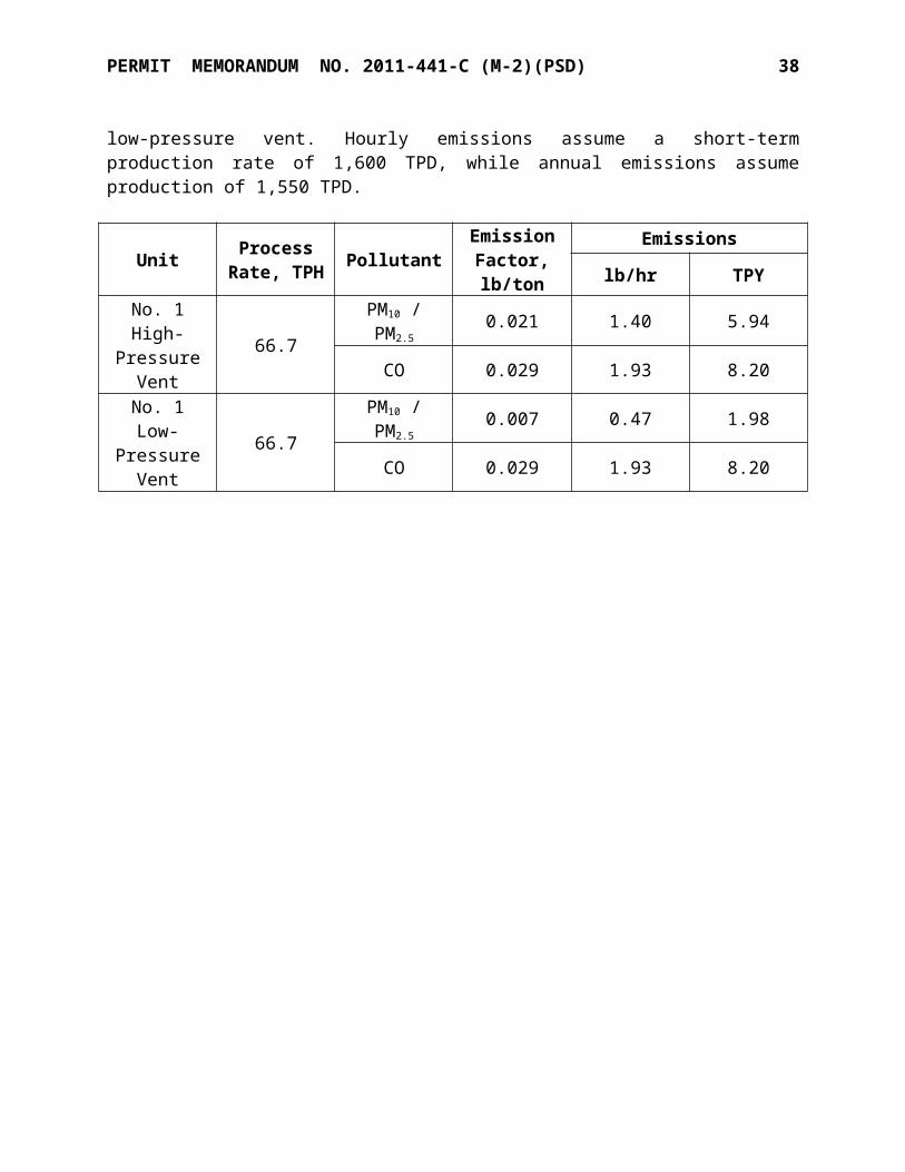
PERMIT MEMORANDUM NO. 2011-441-C (M-2)(PSD) 38
Permanent geological sequestration of CO2 is not a demonstrated technology. The active and planned sequestration projects in the United States and Canada are not demonstrated. The NETL’s 2012 Carbon Utilization and Storage Atlas identifies three active large-scale CO2 injection projects in the United States and Canada, only one of which is a non-EOR sequestration project (Illinois Basin—Mt. Simon Sandstone, near Decatur, Illinois). For planned projects, only the Kevin Dome project in Montana is a non-EOR storage project. None of the active or planned projects has demonstrated the capability to accept 1,318,600 tons per year of CO2 from Enid. The largest active injection site (SECARB’s Cranfield EOR Field) has a total capacity of only 3.4 million metric tons. Further, NETL describes these sites as being evaluated to “validate” the hypothesis that carbon capture, use, and sequestration can be conducted at a commercial scale.
Because of the injection volume limitations of these projects, along with the uncertainty associated with the fate of injected CO2, long-term geologic sequestration has not been successfully applied to the type of source under review. For these reasons, permanent geologic sequestration is not a demonstrated technology for purposes of the Project.
Permanent geological sequestration of CO2 is not an available technology. The large-scale CO2 storage projects identified by NETL have not yet reached the licensing and commercial stage of development. These projects are public-private partnerships, with significant government financial support. The stated purpose of the projects is to “validate that CCS can be conducted at a commercial scale.” The relatively small storage capacities of these projects (the largest of which is only 3.4 million metric tons) supports that they are pilot scale. Technologies in the pilot scale testing stages of development are not considered “available” technologies. Because these pilot scale projects have not yet reached the licensing and commercial stage of development, permanent geological sequestration of CO2 is not an available technology.
Permanent geological sequestration of CO2 is not an applicable technology. The large-scale CO2 storage projects identified by NETL cannot accept the quantity of CO2 that would be produced over the life of the project. NETL itself is assessing whether these projects have the capacity to reliably store CO2 long-term without adverse human health or environmental impacts, and so these projects cannot reliably provide permanent CO2
sequestration for the Project.
- Carbon Transportation CO2 transportation to permanent geological sequestration sites is not a demonstrated technology. There is no CO2 pipeline that has been installed and operated successfully connecting an anthropogenic CO2 source like the project to a permanent geologic sequestration site with sufficient capacity to accept such volumes long term.

PERMIT MEMORANDUM NO. 2011-441-C (M-2)(PSD) 39
CO2 transportation to permanent geological sequestration sites is not an applicable technology. Because there are no technically feasible, large-capacity, reliable, permanent geological sequestration sites, any CO2 pipeline from the Project would be a pipeline to an indeterminate location. Even if one of the large-scale carbon sequestration projects in NETL’s 2012 Atlas were hypothetically capable of serving the project, the logistical hurdles of constructing, owning, and operating a high-capacity CO2 pipeline to one of those sites are high. For example, the closest non-EOR sequestration site noted by NETL would be the Archer Daniels Midland sequestration demonstration project near Decatur, Illinois, approximately 535 miles away from the project. Issues such as obtaining contracts for offsite land acquisition (including the availability of land) and the timing of when the new pipeline would be available relative to the startup of the proposed project would be extraordinarily difficult to overcome.
CO2 transportation to Subpart RR-compliant EOR facilities is neither demonstrated, nor applicable. The existing CO2 compressor and pipeline system at the facility is owned and operated by Merit Energy Company, an independent company, and is used to transport a portion of the current CO2 production off site for use in EOR. As the compressor and pipeline system are owned and operated by Merit, KNC does not control use or maintenance and therefore cannot assure the availability or the reliability of this equipment as a transport system for any particular future needs for purposes of a CO2
control strategy. In addition, because the existing pipeline leads to an EOR field that is not Subpart RR compliant, for the reasons stated above CO2 transportation through this pipeline is neither demonstrated nor applicable and is currently technically infeasible. Since a sequestration site cannot be identified that meets the required availability criteria or assure longevity or viability, the use of an EOR pipeline as part of a CO2 reduction strategy cannot be assured for the life of the Project, and geologic sequestration is not considered an applicable technology.
In summary, because each of the three components of CCS, namely capture, transport and long-term permanent storage is technically infeasible for the life of the project, CCS as a whole is technically infeasible as BACT for the proposed Project.
Alternative Fuels: Natural gas is the lowest GHG emitting fuel and is a feedstock for the reformer process. Alternative fuels would have to be gasified prior to introduction into the process. They are, therefore, infeasible.
The remaining three options (combined heat and power cogeneration, operational energy efficiency measures, and design energy efficiency measures) are currently being conducted at the Enid facility, therefore are both demonstrated and available.
Step 3 Rank Remaining Control Technologies by Control Effectiveness
The following table shows the remaining controls:
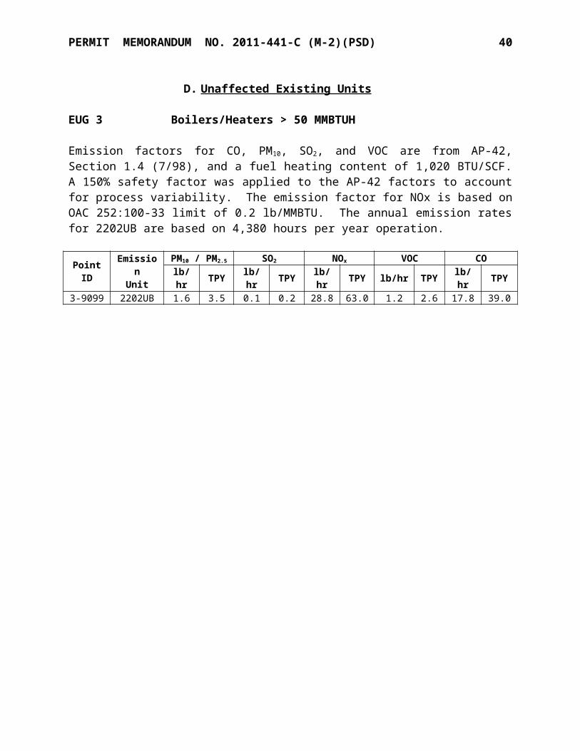
PERMIT MEMORANDUM NO. 2011-441-C (M-2)(PSD) 40
Control Technology Option
Estimated GHG Emission Reduction
Estimated Energy Efficiency Increase Reference
Maintenance and Fouling Control
1-10% of process heater emissions 3-6%
October 2010 EPA GHG BACT Guidance & Energy Star Guide (LBNL-56183, February 2005)
Combustion Air and Feed/Steam Preheat
5% compared to typical reformer
5% compared to typical reformer
October 2010 EPA GHG BACT Guidance
Combustion Air Controls
1-3% of heater emissions 1-3%
October 2010 EPA GHG BACT Guidance
Combined Heat and Power Generation No data available No data --
Step 4. Evaluate Most Effective Controls Based on Energy, Environmental, and Economic Impacts
Under the top-down approach, the highest ranking option is considered first and is evaluated on the basis of cost and collateral environmental impact. Since the highest ranking three options are incorporated in the proposed boiler and modified reformer heaters, along with several other options, costs have not been evaluated.
Though CCS has been found not to be technically feasible under Step 2, and therefore need not be ranked under Step 3 nor evaluated under Step 4, KNC voluntarily provided an analysis of economic feasibility and of the energy and environmental impacts of CCS in its application. KNC concluded that the capital costs associated with implementing CCS for the reformer and boilers, comprised of a CO2 scrubber, compressor and pipeline (from Enid, OK to Decatur, IL), would be approximately $841,000,000 to $903,000,000. Based on recent economic infeasibility analyses by EPA Region VI in support of BACT decisions for GHG PSD permits, these capital cost analyses are reasonable estimates, and if they were necessary for the BACT analysis we would conclude that the use of CCS in the proposed project would make the project economically infeasible. The energy and environmental impacts analysis set forth in the permit application further support the conclusion that CCS is not BACT.
Step 5. Select BACT and Document the Selection as BACT
The following combination of energy efficiency techniques is selected as BACT:
- Combined heat and power cogenerations (CHP)- Operational energy efficiency measures- Design energy efficiency measures
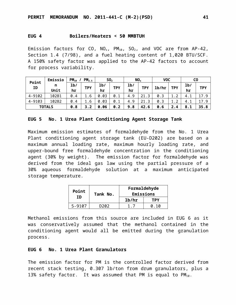
PERMIT MEMORANDUM NO. 2011-441-C (M-2)(PSD) 41
A limit of 117 lb/MMBTU CO2 will be established for new and modified combustion sources.
ii. Process Sources
Step 1. Identify Available Control Technologies
The application identified the following potential control technologies:
- Carbon capture and sequestration (CCS)- Good design practices- Good operating practices
The category, “Good design practices,” includes the following items:
- Improved CO2 removal- Small catalyst in ammonia converters - Hydrogen recovery from purge gas.
These items focus both on optimal recovery of CO2 and minimizing generation of CO2 in reforming; the more hydrogen is recovered and recycled, the less that must be generated. The “small catalyst” refers to a configuration with reduced pressure drop, which reduces energy consumption in pushing reactants through the catalyst.
The category, “Good operating practices,” includes the following items:
- Maintenance of pressure balance between ammonia and urea plants, minimizing venting of CO2
CO2 is a feed for urea formation. The more efficiently it is supplied (not oversupplied) to the urea reactor, the less is vented from the urea reactor.
The following table shows the results of a search of EPA’s RBLC for BACT for sources of greenhouse gas emissions: process sources.
Carbon Dioxide Regenerators – Greenhouse Gases
RBLC ID Facility State
Permit Issuance
DateBACT Limit
IA-0105 Iowa Fertilizer Iowa 10/26/12 Not statedIA-0106 CF Industries Iowa 7/12/13 Not stated
PERMIT MEMORANDUM NO. 2011-441-C (M-2)(PSD) 42
Step 2. Eliminate Technically Infeasible Options
Similarly to combustion units, carbon capture and sequestration is not a demonstrated technology. The technology necessary to recover process CO2 from the ammonia synthesis process has been demonstrated and operated successfully, and is available and applicable, and therefore the capture of process CO2 from this source is technically feasible. However, the transportation and permanent storage of process CO2 generated at this facility that is not sold as a product are both technically infeasible, based on the same conclusions set forth above. Since two of the three components of CCS are technically infeasible, CCS is considered technically infeasible as a control technology. All other controls mentioned in Step 1 are either currently in use or are being designed into the system.
Step 3. Rank Remaining Control Technologies by Control Effectiveness
Data are not yet available to complete such a ranking since most ammonia process systems, including this facility, are designed and operated with all remaining controls in place, therefore it is not possible to evaluate the effects of individual measures.
Step 4. Evaluate Most Effective Controls Based on Energy, Environmental, and Economic Impacts
As stated above in the Combustion CO2 step 4 evaluation, an economic evaluation was completed for CCS. CCS as a control strategy for process CO2 emissions is not economically feasible. The most effective feasible controls are being designed into the proposed project.
Step 5. Select BACT and Document the Selection as BACT
The following combination of energy efficiency techniques is selected as BACT:
- Good design practices- Good operating practices
The facility is proposing a limit of CO2 emissions of 1,260,000 tons per year, 12-month rolling total.
B. CO BACT Review
Carbon monoxide is formed primarily as a result of incomplete combustion of fuel, and to a lesser degree, from incomplete reaction in steam reforming; over 98% of CO emitted is from combustion units. For combustion units, control of CO is accomplished by providing adequate fuel residence time and high temperature in the combustion zone to ensure complete combustion; for reforming, having a complete “CO shift” reaction is necessary to minimize CO. These control factors also tend to result in high NOX and GHG emissions. Since efficient operation of reformers is part of GHG BACT, and 98% of CO is emitted from combustion units, the BACT analysis for CO will focus on combustion units: the two modified reformers and the proposed new No. 2 Urea Plant boiler.

PERMIT MEMORANDUM NO. 2011-441-C (M-2)(PSD) 43
CO emissions from combustion units are a function of oxygen availability (excess air), flame temperature, residence time at flame temperature, combustion zone design, and turbulence. Alternative CO control methods include exhaust gas cleanup methods such as catalytic oxidation, and front-end methods such as combustion control wherein CO formation is suppressed within the combustors.
A search of EPA’s RBLC follows. It was noted that only two BACT determinations relied on an oxidative catalyst, while all others relied on good combustion. Non-feasibility of oxidative catalysts will be discussed later.
Natural Gas Fired Primary Boilers > 250 MMBTUH – Carbon Monoxide
RBLC ID Facility State
Permit Issuance
DateBACT Limit
FL-0350 Port Dolphin Energy Florida 12/01/11Good combustion practices, 0.015 lb/MMBTU CO
IA-0105 Iowa Fertilizer Iowa 10/26/12Good combustion practices, 0.0013 lb/MMBTU CO
IA-0106 CF Industries – Port Neal Iowa 7/12/13 Oxidation catalyst, 0.0013 lb/MMBTU
LA-0231 Lake Charles Gasification Louisiana 6/22/09Good design and proper
operation, 0.036 lb/MMBTU
LA-0254 Ninemile Point Generating Louisiana 8/16/2011Good combustion,
natural gas fuel, 0.084 lb/MMBTU
NE-0054 Cargill, Inc. Nebraska 3/01/13 Good combustion practices
NV-0049 Harrah’s Operating Co. Nevada 8/20/09 Operation within mfg specs, 0.037 lb/MMBTU
NV-0049 Harrah’s Operating Co. Nevada 8/20/09 Flue gas recirculation, 0.0705 lb/MMBTU
NV-0049 Harrah’s Operating Co. Nevada 8/20/09Operation within mfg
specs, 0.0173 lb/MMBTU
NV-0049 Harrah’s Operating Co. Nevada 8/20/09Operation within mfg
specs, 0.0172 lb/MMBTU
NV-0049 Harrah’s Operating Co. Nevada 8/20/09Operation within mfg
specs, 0.0073 lb/MMBTU

PERMIT MEMORANDUM NO. 2011-441-C (M-2)(PSD) 44
RBLC ID Facility State
Permit Issuance
DateBACT Limit
NV-0049 Harrah’s Operating Co. Nevada 8/20/09Operation within mfg
specs, 0.0075 lb/MMBTU
NV-0049 Harrah’s Operating Co. Nevada 8/20/09 Operation within mfg specs, 0.037 lb/MMBTU
NV-0049 Harrah’s Operating Co. Nevada 8/20/09 Operation within mfg specs, 0.848 lb/MMBTU
NV-0049 Harrah’s Operating Co. Nevada 8/20/09 Operation within mfg specs, 0.074 lb/MMBTU
NV-0050 MGM Mirage Nevada 11/30/09Good combustion practices, gas fuel, 0.0184 lb/MMBTU
NV-0050 MGM Mirage Nevada 11/30/09Good combustion practices, gas fuel, 0.0214 lb/MMBTU
NV-0050 MGM Mirage Nevada 11/30/09Good combustion practices, gas fuel, 0.0362 lb/MMBTU
NV-0050 MGM Mirage Nevada 11/30/09Good combustion
practices, gas fuel, 0.037 lb/MMBTU
NV-0050 MGM Mirage Nevada 11/30/09Good combustion
practices, gas fuel, 0.038 lb/MMBTU
NV-0050 MGM Mirage Nevada 11/30/09Good combustion practices, gas fuel, 0.0148 lb/MMBTU
NV-0050 MGM Mirage Nevada 11/30/09Good combustion
practices, gas fuel, 0.035 lb/MMBTU
SC-0091 Columbia Energy South Carolina 7/00/03 Good combustion, clean
fuel, 0.06 lb/MMBTU

PERMIT MEMORANDUM NO. 2011-441-C (M-2)(PSD) 45
Step 1. Identify Available Control Technologies
The application identified two control technologies:- Good combustion practices- Catalytic oxidation
While secondary non-catalytic oxidation could have been included in the listing, it would have been eliminated at the step of technical feasibility. The two listed options illustrate CO control adequately, either by preventing formation (good combustion practices) or by removal (catalytic oxidation). Catalytic oxidation normally requires a temperature in the range of 500 to 700oF to function properly with maximum catalyst lifespan.
Step 2. Eliminate Technically Infeasible Options
The discharge temperature of exhausts from the boiler and reformer heaters is typically less than 400oF, below the range required for catalytic oxidation to function. Increasing temperatures would require either additional fuel consumption or lowering of heat recovery, items which are at odds with GHG BACT. A review of RBLC shows that only two of the recently-permitted gas-fired boilers or primary reformers have required oxidative catalysts. Oxidative catalysts must be eliminated from the list of potentially-feasible controls due to the temperature issues, leaving only good combustion practices.
Step 3. Rank Remaining Control Technologies by Control Effectiveness
Good combustion controls is the only CO control option left to rank.
Step 4. Evaluate Most Effective Controls Based on Energy, Environmental, and Economic Impacts
Good combustion controls are the only CO control option remaining.
Step 5. Select BACT and Document the Selection as BACT
Good combustion is accepted as BACT for CO emissions from the proposed No. 2 Urea Plant boiler at 0.037 lb/MMBTU (3-hour average) and the modified ammonia plant reformer heaters at 0.084 lb/MMBTU (3-hour average).
C. Particulate Matter (PM10 / PM2.5) BACT Review
The new or modified emissions units subject to a BACT analysis are the modified reformer heaters, No. 2 Urea Plant boiler, urea granulator, new No. 2 Urea Plant cooling tower, new and modified synthesis vents, haul roads, and materials handling/storage and truck/railcar loading. The BACT analysis will address these as categories of combustion units, process units, cooling towers, materials handling, and roads. Since the controls for both PM10 and PM2.5 are nearly identical, the two pollutants will be analyzed as a single category.
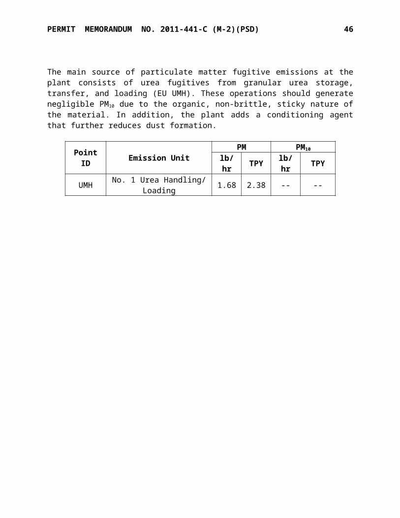
PERMIT MEMORANDUM NO. 2011-441-C (M-2)(PSD) 46
i. Urea Granulators
Step 1 - Identify All Control Technologies
The following add-on controls were identified as technologies available to control PM emissions from solid nitrogen fertilizer production facilities.
- Wet scrubbers- Fabric filters (baghouses)- Mechanical collectors (cyclones)- Electrostatic precipitators (dry and wet)
A search of EPA’s RBLC showed the following results. The RBLC database showed the emissions limits but did not include the types of technologies being used to achieve those results.
Urea Granulators – Particulate Matter
RBLC ID Facility State
Permit Issuance
DateBACT Limit
IA-0105 Iowa Fertilizer Iowa 10/26/120.1 kg/metric tonne total
PM and PM10, 0.025 kg/metric tonne PM2.5
IA-0106 CF Industries Port Neal Iowa 7/12/13 0.11 lb/tonOK-0124 Koch Industries Enid Plant Oklahoma 5/01/08 0.31 lb/tonOK-0135 Pryor Chemical Oklahoma 2/23/09 0.042 lb/ton
Wet ScrubbersWet scrubbers are widely used in the solid urea manufacturing industry and are preferred over other controls for a variety of reasons, not the least of which is the ability to recycle urea back to the process. Three types of wet scrubbers were analyzed: spray-tower scrubbers, impingement-type scrubbers, and venturi scrubbers. All of these scrubbers work by capturing small solids in a larger water droplet which is then captured in a mist eliminator or equivalent.
Fabric Filter Baghouse
A fabric filter baghouse (FF) removes solids from the flue gas by drawing dust-laden flue gas through a bank of filter tubes. A filter cake, composed of the removed particles, builds up on the dirty side of the bag. Periodically, the cake is removed through physical mechanisms such as a blast of air from the clean side of the bag, or mechanical shaking of the bags, which causes the cake to fall. The dust is then collected in a hopper and removed. Fabric filters include reverse gas fabric filters (RGFF) or pulse jet fabric filters (PJFF). In a PJFF, the solids are collected on the outside of the bags. A PJFF can operate at higher air-to-cloth ratios than a reverse gas system. Consequently, a PJFF is smaller and will usually have lower capital costs than a RGFF. The bags in a RGFF, however, can be expected to have a longer service life. Consequently, an RGFF will typically have lower operating costs than a PJFF. For the purposes of this BACT analysis, a distinction is not made between RGFF and PJFF.

PERMIT MEMORANDUM NO. 2011-441-C (M-2)(PSD) 47
Mechanical Collectors followed by Particulate Scrubbers
Other technologies available are mechanical collectors such as centrifugal separators (cyclones). However, these technologies do not achieve the removal efficiency of wet scrubbers.
Electrostatic Precipitator (ESP)
An electrostatic precipitator (ESP) removes dust or other fine particles from the flue gas by charging the particles inductively with an electric field and then attracting the particles to highly charged collector plates, from which they are removed. An ESP consists of a hopper-bottomed box containing rows of plates forming passages through which the flue gas flows. Centrally located in each passage are emitting electrodes energized with a high-voltage, negative polarity direct current. The voltage applied is high enough to ionize the gas molecules close to the electrodes, resulting in a corona current of gas ions from the emitting electrodes across the gas passages to the grounded collecting plates. When passing through the flue gas, the charged ions collide with, and attach themselves to, particles suspended in the gas. The electric field forces the charged particles out of the gas stream towards the grounded plates, and there they are collected in a layer. The plates are periodically cleaned by a mechanical rapping system to release the PM layer into hoppers as an agglomerated mass. Factors affecting the efficiency of the ESP include flue gas flow rate, resistivity of the PM, plate area, voltage, number of sections, and overall power consumption.
Wet ESP
A wet ESP operates in the same three-step process as a dry ESP: charging, collection, and removal. However, the removal of particles from the collecting electrodes is accomplished by washing of the collection plate surface using liquid, rather than mechanical rapping of the plates. A wet ESP is more widely used in applications where the gas stream has high moisture content, is below the dew point, or includes sticky particles.
Step 2-Eliminate Technically Infeasible Options
The urea to be handled is an organic material and quite sticky as well as hygroscopic (absorbs water from surrounding gases). Both properties result in urea PM sticking to fabric filters, “blinding” them, and not being recoverable.
The stickiness also creates similar problems in dry ESPs, where the dust collected from an exhaust stream cannot be readily recovered, resulting in accumulation in the ESP. Although cyclones are somewhat less efficient than wet scrubbers, they appear to be equally vulnerable to plugging.
Theoretically, wet ESPs could collect sticky material, but the RBLC database does not show any applications. Wet ESPs, therefore, are not demonstrated technology for this application.
PERMIT MEMORANDUM NO. 2011-441-C (M-2)(PSD) 48
Step 3-Rank Remaining Control Technologies by Control Effectiveness
The highest-efficiency feasible control technology is wet scrubbing; several different wet scrubber designs are feasible. The applicant proposes a limit of 0.1 lb/ton PM. This proposed limitation is more stringent than any other BACT determination except for Pryor Chemical, which has not yet demonstrated compliance with their proposed limit.
Step 4- Evaluate Most Effective Controls for Energy, Environmental, and Economic Impacts
The applicant has selected wet scrubbing as the control technology for control of PM emissions, which is considered the best technology available.
Step 5-Select BACT and Document the Selection as BACT
The high-efficiency wet scrubbers are acceptable as BACT for the new urea granulator. A PM limit of 0.1 lb/ton will be established in the permit.
ii. Solids Handling And Loading
Step 1 - Identify All Control Technologies
The BACT analysis identified the following control options:
- Fabric filters- Mechanical collectors- Full or partial enclosures- Telescoping Chutes- Wet suppression- Conditioning agents
It should be noted that some operations, especially the loading operations, will have long periods of inactivity interspersed with near-maximum short-term operations. These load swings complicate the control technology analysis.
Fabric Filter Baghouse
A fabric filter baghouse (FF) removes solids from the flue gas by drawing dust-laden flue gas through a bank of filter tubes. Since this analysis is essentially identical to the analysis for the urea granulators, that text will not be repeated.
Mechanical Collectors
This discussion is also identical to the discussion for the urea granulators.

PERMIT MEMORANDUM NO. 2011-441-C (M-2)(PSD) 49
Enclosures
Enclosures prevent entrainment of particulates by isolation from wind or other disturbances. They have the advantage of being compatible with most process equipment and can enhance product quality.
Telescoping Chutes
Telescoping chutes are used in intermittently-used operations such as load-out. They are lowered into railcars to minimize disturbance of materials during loading operations.
Conditioning Agents
A conditioning agent in the solids handled can reduce brittleness, thus reduce the tendency to fracture into small particles which are susceptible to becoming airborne. It may also enhance the tendency of small particles to stick to each other, forming larger particles which are more prone to settle out gravimetrically.
Wet Suppression
Wet suppression is often used in loading and handling solids, minimizing dust losses. However, since urea is hydrophilic and hygroscopic, any water applied would be readily absorbed into the solids and would create a cake of granulated solids.
Step 2-Eliminate Technically Infeasible Options
A review of the RBLC indicates that, for all of the solid urea plants permitted in the United States during the previous 10 years, conditioning agents, and enclosures have all been accepted in the solid fertilizer industry. Most more-involved systems cannot follow load swings for intermittent operations.
BACT Determinations: Urea Handling & Loading – Particulate Matter
RBLC ID Facility State
Permit Issuance
DateBACT Limit
IA-0106 CF Industries Port Neal Iowa 7/12/13 Bin Vent Filter, 0.0011 lb/ton
OK-0124 Koch Industries Enid Plant Oklahoma 5/01/08Enclosure, telescopic chutes, conditioning
agent
Mechanical collectors such as cyclones are not demonstrated technology given the tendency of urea to stick to the cyclone interiors. Similarly, fabric filters would be impractical due to the stickiness of the urea.
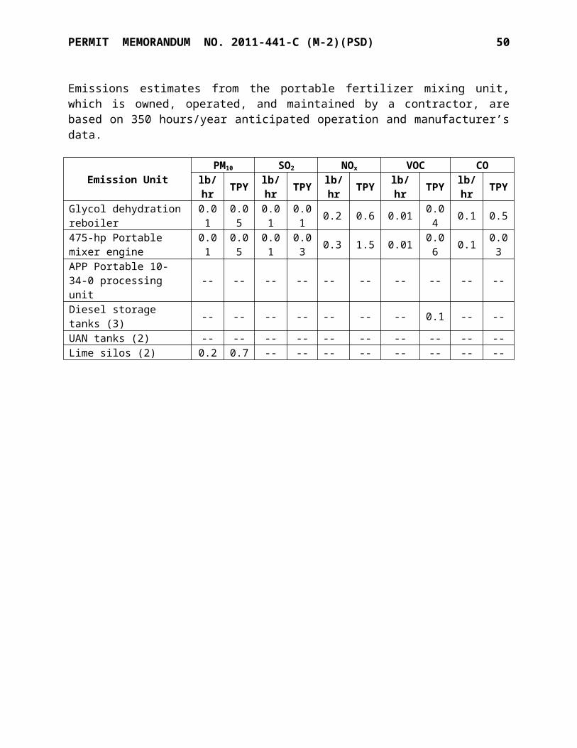
PERMIT MEMORANDUM NO. 2011-441-C (M-2)(PSD) 50
Step 3-Rank Remaining Control Technologies by Control Effectiveness
Enclosures provide approximately 85% control. Product conditioning is expected to achieve 90% control, while telescopic chutes should provide approximately 75% control. Used in tandem, the three measures achieve 99.6% control of PM.
The facility adds a conditioning agent as a matter of course.
Step 4- Evaluate Most Effective Controls for Energy, Environmental, and Economic Impacts
The applicant has selected enclosures (full or partial, depending on the operation) as the control technology for control of PM emissions from handling and storage. These units prevent emissions to the atmosphere while maintaining product quality. There is a minimum of waste created by these options.
Telescoping chutes and enclosures will be used for loading operations.
Step 5-Select BACT and Document the Selection as BACT
Enclosures of handling and storage facilities, use of conditioning agents in the urea production, and telescoping chutes on loading operations, are acceptable as BACT.
iii. Cooling Towers
Particulate emissions occur from the cooling tower as a result of the total solids (suspended and dissolved metals and minerals) in the water being entrained in the air stream. Mist eliminators prevent most of the water from escaping out the top of the tower; however, some water droplets (with dissolved and suspended particulate) do escape the cooling tower and are referred to as “drift”. For this analysis, as a simplifying conservative assumption, all of the particulate resulting from the drift is considered to be PM10.
Step 1-Identify All Control Technologies
There are several ways to reduce drift (and resulting PM and PM10) emissions from cooling towers. Process modifications could be considered, including elimination of a cooling tower by using an available water source such as a stream or nearby water reservoir or lake to provide enough water to use “once through” cooling. A standard cooling tower is similar to a once through system except the water is recycled in the tower. Another alternative is the use of air fin cooling. A third alternative is to use a hybrid system that combines some aspects of a wet and a dry system. A fourth option is the installation of modern high efficiency drift eliminators on the cooling tower.
A search of EPA’s RBLC showed that cooling tower PM emissions were controlled almost exclusively by drift eliminators. Three determinations also limited the total dissolved solids content of the cooling waters (two in Nevada and one in Virginia), both of which allowed a much higher drift than 0.0005%

PERMIT MEMORANDUM NO. 2011-441-C (M-2)(PSD) 51
Cooling Towers – Particulate Matter
RBLC ID Facility State
Permit Issuance
DateBACT Limit
FL-0316 Levy Nuclear Plant Florida 2/20/09 Drift eliminators, 0.0005% drift
FL-0317 FPL Turkey Point Nuclear Plant Florida 5/30/09 Drift eliminators,
0.0005% driftFL-0322 Sweet Sorghum-to-Ethanol Florida 12/23/10 Not stated
GA-0141 Warren County Biomass Energy Georgia 12/17/10 Drift eliminators,
0.0005% drift
GA-0142 Osceola Steel Georgia 12/29/10 Drift eliminators, 0.0005% drift
IA-0106 CF Industries Iowa 7/12/13 Drift eliminators, 0.0005% drift
ID-0017 Power County Advanced Energy Idaho 2/10/09 Drift eliminators,
0.0005% driftID-0018 Langley Gulch Power Plant Idaho 6/25/10 Drift eliminators
LA-0204 Plaquemine PVC Louisiana 2/27/09
Good design, maintenance, drift eliminators, 0.057
lb/MMGalLA-0213 St. Charles Refinery Louisiana 11/17/09 Drift eliminatorsLA-0264 Norco Hydrogen Louisiana 9/14/12 Drift eliminatorsMI-0400 Wolverine Power Michigan 6/29/11 Drift eliminators
MI-0401 Midland Power Station Michigan 12/21/11 Drift eliminators, 0.0005% drift
MN-0078 Sappi Cloquet Minnesota 10/28/09 Drift eliminators
NV-0049 Harrah’s Operating Nevada 8/20/09Drift eliminators, 0.005% drift, TDS below 2,520 ppm
NV-0049 Harrah’s Operating Nevada 8/20/09Drift eliminators, 0.005% drift, TDS below 3,000 ppm
NV-0050 MGM Mirage Nevada 11/30/09Drift eliminators, 0.001% drift, TDS below 3,600 ppm
TX-0551 Panda Sherman Power Station Texas 2/03/10 Drift eliminators, 0.0005% drift
TX-0552 Wolf Hollow Power Plant No. 2 Texas 3/03/10 Drift eliminators,
0.0005% drift
TX-0553 Lindale Renewable Energy Texas 1/08/10 Drift eliminators, 0.0005% drift

PERMIT MEMORANDUM NO. 2011-441-C (M-2)(PSD) 52
RBLC ID Facility State
Permit Issuance
DateBACT Limit
VA-0319 Gateway Cogeneration Smart Water Project Virginia 8/27/12
Drift eliminators, 0.001% drift, TDS below 1,200 ppm
WY-0072 Granger Facility Wyoming 6/12/13 Drift eliminators, 0.0005% drift
Step 2-Eliminate Technically Infeasible Options
“Once through” cooling is not a feasible option in this location. Several studies have shown that both the dry cooling system (air fins) and the wet/dry hybrid system have an impact on system performance (i.e., reduce the available power output) during the hottest parts of the year. The only feasible option at this location is a wet cooling tower with high efficiency drift eliminators. Since only one control option is feasible, Steps 3 and 4 are not necessary.
Step 5-Select BACT and Document the Selection as BACT
The applicant proposed that high efficiency drift eliminators, with the capability to reduce the potential drift to a maximum of 0.0005% of the circulating water flow rate, is BACT for PM10
and PM2.5 control at the cooling tower. The proposed control technology is acceptable as BACT. Compliance will be demonstrated by vendor guarantees, and the facility will be required to show TDS contents periodically.
iv. Combustion Units
Step 1 - Identify All Control Technologies
The following add-on controls were identified as technologies available to control PM emissions from solid nitrogen fertilizer production facilities.
- Wet scrubbers- Fabric filters (baghouses)- Mechanical collectors (cyclones)- Electrostatic precipitators (dry and wet)- Fuel selection / good combustion practices
A search of EPA’s RBLC showed the following results.

PERMIT MEMORANDUM NO. 2011-441-C (M-2)(PSD) 53
Natural Gas Fired Primary Reformers – Particulate Matter
RBLC ID Facility State
Permit Issuance
DateBACT Limit
IA-0105 Iowa Fertilizer Iowa 10/26/12Good combustion practices, 0.0024 lb/MMBTU TPM
LA-0211 Garyville Refinery Louisiana 12/27/06Proper design and operation, 0.0075
lb/MMBTU
LA-0264 Norco Hydrogen Louisiana 9/04/12
Proper equipment design, good
combustion practices, gas fuel
OK-0134 Pryor Chemical Oklahoma 2/23/09 Not statedOK-0135 Pryor Chemical Oklahoma 2/23/09 Not statedPA-0231 United Refinery Pennsylvania 10/09/03 Good combustionTX-0526 Air Products Texas 8/18/06 Not stated
Natural Gas Fired Primary Boilers – Particulate Matter
RBLC ID Facility State
Permit Issuance
DateBACT Limit
IA-0105 Iowa Fertilizer Iowa 10/26/12Good combustion practices, 0.0024 lb/MMBTU TPM
IA-0106 CF Industries Iowa 7/12/13
Good combustion practices, gas fuel, 0.0024 lb/MMBTU
TPM
LA-0231 Lake Charles Gas Louisiana 6/22/09 Good design and proper operation
LA-0254 Ninemile Point Louisiana 8/16/11 Good combustion, natural gas fuel
MN-0078 Sappi Cloquet Minnesota 10/28/09 0.007 lb/MMBTU
NE-0054 Cargill, Inc. Nebraska 3/01/13 Good combustion practices
SC-0091 Columbia Energy South Carolina 7/03/03
Good combustion practices, 0.005
lb/MMBTU
It is noted that the Iowa determinations for PM from gas-fired units are approximately 1/3 of the values in AP-42, Section 1.4, and without any add-on controls.

PERMIT MEMORANDUM NO. 2011-441-C (M-2)(PSD) 54
Wet Scrubbers
Wet scrubbers are widely used. All of these scrubbers work by capturing small solids in a larger water droplet which is then captured in a mist eliminator or equivalent. There would be the added benefit of cooling exhaust streams, condensing condensable PM. However, their effectiveness is limited for small-diameter particles.
Fabric Filter Baghouse
A fabric filter baghouse (FF) removes solids from the flue gas by drawing dust-laden flue gas through a bank of filter tubes. A filter cake, composed of the removed particles, builds up on the dirty side of the bag. Periodically, the cake is removed through physical mechanisms such as a blast of air from the clean side of the bag, or mechanical shaking of the bags, which causes the cake to fall. The dust is then collected in a hopper and removed. However, the effectiveness of baghouses is limited for submicron particles and negligible for condensable PM; the gas stream would have to be cooled adequately to condense condensable PM for the baghouses to have any beneficial effect.
Mechanical Collectors followed by Particulate Scrubbers
Other technologies available are mechanical collectors such as centrifugal separators (cyclones). However, these technologies do not achieve the removal efficiency of wet scrubbers. Mechanical collectors are rarely used for PM smaller than 5 microns, and most PM from natural gas combustion is expected to be PM2.5.
Electrostatic Precipitator (ESP)
An electrostatic precipitator (ESP) removes dust or other fine particles from the flue gas by charging the particles inductively with an electric field and then attracting the particles to highly charged collector plates, from which they are removed. Factors affecting the efficiency of the ESP include flue gas flow rate, resistivity of the ash, plate area, voltage, number of sections, and overall power consumption. Similarly to other potential controls, the gas stream must be cooled first to condense condensable PM. The condensable PM is largely soot, salts, and condensed organic vapors, all of which have inadequate resistivity to hold a surface charge.
Wet ESP
A wet ESP operates in the same three-step process as a dry ESP: charging, collection, and removal. However, the removal of particles from the collecting electrodes is accomplished by washing of the collection plate surface using liquid, rather than mechanical rapping of the plates. A wet ESP is more widely used in applications where the gas stream has high moisture content, is below the dew point, or includes sticky particles.
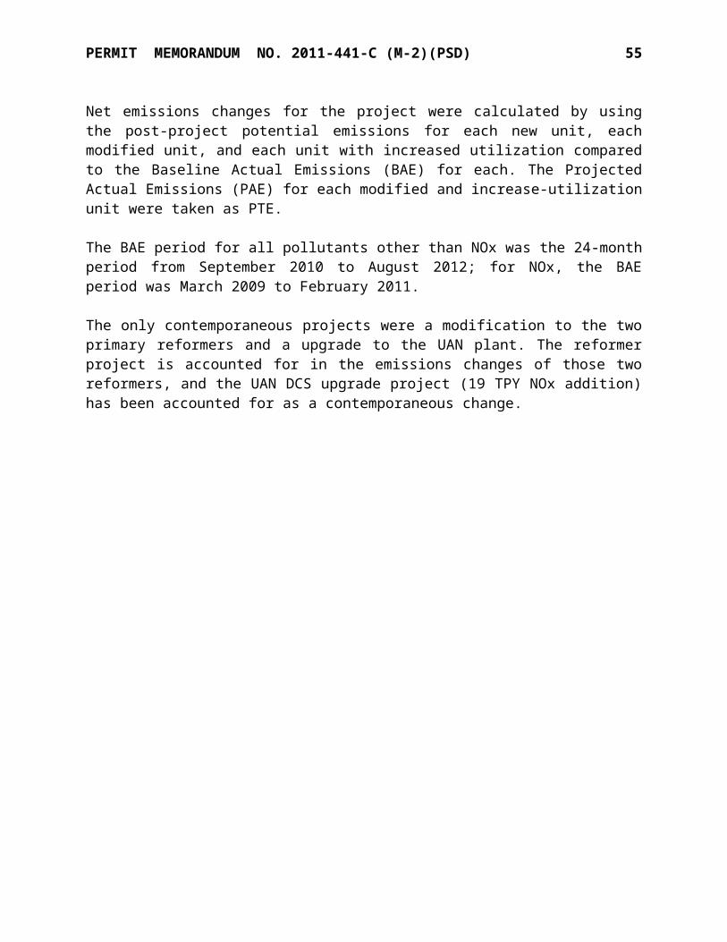
PERMIT MEMORANDUM NO. 2011-441-C (M-2)(PSD) 55
Step 2-Eliminate Technically Infeasible Options
A search of RBLS shows no add-on controls being used for gas-fired units. The only practical control technology is use of gas fuel, which is low-emitting fuel.
Step 3-Rank Remaining Control Technologies by Control Effectiveness
The only remaining control technology is natural gas fuel.
Step 4- Evaluate Most Effective Controls for Energy, Environmental, and Economic Impacts
The only remaining control technology is natural gas fuel.
Step 5-Select BACT and Document the Selection as BACT
The use of natural gas fuel is acceptable as BACT for the new boiler and modified reformer heaters. A PM, PM10, and PM2.5 limit based on 0.0076 lb/MMBTU will be established in the permit.
SECTION VII. EVALUATION OF EXISTING AIR QUALITY AND DETERMINATION OF MONITORING REQUIREMENTS
Model Selection and Description
Consistent with the available modeling applications provided for by Appendix W to Part 51 Guideline on Air Quality Models, the AERMOD (Version 12345) air dispersion model is used to predict maximum ground-level concentrations associated with the proposed project’s emissions. AERMOD is a refined, multi-source Gaussian plume model. The modeling analysis was performed using regulatory default options including stack-tip downwash and missing data processing.
Terrain Considerations
Per AQD guidance, modeling with elevated terrain was conducted. AERMAP (version 11103), a preprocessor that takes digital elevation data from the US Geologic Survey (USGS), was used to assign elevations to stack, buildings, receptors, and hills. The base elevation of the facility is approximately 1,204 feet above mean sea level.
USEPA guidance supports the use of AERSURFACE to process land cover data to determine the surface characteristics (i.e., surface roughness, Bowen ratio, and albedo) for the meteorological measurement site that is used to represent meteorological site conditions. Chapter 2.3.4 of ODEQ’s Air Dispersion Modeling Guidelines for Oklahoma Air Quality Permits also indicates that surface characteristics using AERSURFACE can be used for air permit applications. The GeoTIFF file for Oklahoma containing the land cover data is used as input for AERSURFACE. ODEQ’s modeling guidance document also recommends the following input conditions for running AERSURFACE:

PERMIT MEMORANDUM NO. 2011-441-C (M-2)(PSD) 56
Center the land cover analysis on the meteorological measurement site. Analyze surface roughness within 1 km of measurement site. Utilize one sector determining the surface roughness length. Temporal resolution of the surface characteristics should be determined on a monthly basis. The region does not experience continuous snow cover for most of the winter. The Mesonet site is not considered an airport. The region is not considered an arid region. Utilize the default season assignment (winter=Dec, Jan, Feb; Spring=Mar, Apr, May;
Summer=Jun, Jul, Aug; Fall=Sep, Oct, Nov)
Background Concentrations
Regional monitoring data from Monitoring Site ID 401091037, located in Oklahoma City, is considered representative of the background concentrations in the affected area of the KNC Enid facility for purposes of the Class II modeling and within 50 km of the KNC Enid facility for purposes of the Class I modeling. Accordingly, site-specific pre-construction monitoring will not be required.
Good Engineering Practice and Building Downwash Evaluation
The dispersion of a plume can be affected by nearby structures when the stack is short enough to allow the plume to be significantly influenced by surrounding building turbulence. This phenomenon, known as structure-induced downwash, generally results in higher model-predicted ground-level concentrations in the vicinity of the influencing structure. Sources included in a PSD permit application are subject to Good Engineering Practice (GEP) stack height requirements outlined in OAC 252:100-8-1.5. GEP stack height is defined as the greater of 65 meters or a height established by applying the formula Hg = H + 1.5L, where:
Hg = GEP stack height,H = height of nearby structures, and L = lesser dimension (height or projected width) of nearby structures,
or by a height demonstrated by a fluid model or a field study that ensures that emissions from a stack do not result in excessive concentrations of any pollutant as a result of atmospheric downwash, wakes, or eddy effects created by the source itself, nearby structures, or nearby terrain features.
The model utilizes the EPA Building Profile Input Parameters (BPIP) program with the plume rise model enhancements (PRM). BPIP-PRIME determines the effect of building downwash on each plume in calculation of maximum impacts.

PERMIT MEMORANDUM NO. 2011-441-C (M-2)(PSD) 57
Meteorology and Surface Characteristics
Five years (2006, 2007, 2008, 2009, and 2010) of processed Oklahoma Mesonet data from Guthrie, Oklahoma and Enid, Oklahoma (Woodring Regional Airport) were combined with data from the National Climatic Data Center (NCDC) and Norman Max Westheimer Airport Upper Air (UA) rawinsonde observation (RAOB) data from the Forecast System Laboratories (FSL). Oklahoma Mesonet data was provided to the AQD courtesy of the Oklahoma Mesonet, a cooperative venture between Oklahoma State University (OSU) and the University of Oklahoma (OU) and supported by the taxpayers of Oklahoma.
When using AERMET to prepare the meteorological data for AERMOD, the surface characteristics (Albedo, Bowen Ratio, and Surface Roughness Length) for the primary (MESONET) and secondary (NCDC-ISD) meteorological sites were determined using AERSURFACE.
Receptor Grid
The AERMOD model allows the user to have the model calculate impacts at user defined discrete and/or flagpole receptors. Discrete receptors are those that are placed at precise locations that may be of interest due to their sensitive nature. Flagpole receptors are receptors that are located above ground level. The ODEQ Air Dispersion Modeling Guidelines does not mention the application of any discrete or flagpole receptors; therefore, no discrete or flagpole receptors are used in the modeling analysis.
Six Cartesian grids for the modeling analyses were defined as follows:
1. A Fence Line Grid containing receptors spaced at 50 meter intervals along the facility fence line.
2. A Fine Grid containing receptors spaced at 100 meter intervals extending approximately 1.0 km from the fence line, exclusive of the Fence Line Grid.
3. A 250-meter grid containing receptors spaced at 250 meter intervals extending approximately 2.5 km beyond the Fine Grid.
4. A 500-meter grid containing receptors spaced at 500 meter intervals extending approximately 5.0 km beyond the 250-meter grid.
5. A 750-meter grid containing receptors spaced at 750 meter intervals extending approximately 7.5 km beyond the 500-meter grid.
6. A 1,000-meter grid containing receptors spaced at 1,000 meter intervals extending approximately 50.0 km beyond the 750-meter grid.
Secondary PM2.5 Formation Modeling
On March 4, 2013, EPA published “Draft Guidance for PM2.5 Permit Modeling.” According to the draft guidance, since the proposed project will have an emission increase greater than 10 TPY of PM2.5 but less than 40 TPY apiece of NOx and SO2, only primary PM2.5 emissions have to be considered.

PERMIT MEMORANDUM NO. 2011-441-C (M-2)(PSD) 58
Source Input Parameters
The modeled stack point source parameters and emission rates for the Enid facility are shown following.
Source Height
Temp Velocity Diameter Elevation PM2.5 PM10 CO
feet oF ft/sec inches feet lb/hr lb/hr lb/hrNew boiler 200 300 49.6 84 1203 3.35 3.35 16.65New granulator 225 117 110.2 108 1200 6.04 6.04 0.00New cooling tower 1 47 78 36.4 216 1208 <0.01 0.05 0.00New cooling tower 2 47 78 36.4 216 1209 <0.01 0.05 0.00New cooling tower 3 47 78 36.4 216 1210 <0.01 0.05 0.00New cooling tower 4 47 78 36.4 216 1211 <0.01 0.05 0.00Existing A2 Cooling Tower 1 67 78 77.9 240 1209 <0.01 0.01 0.00
Existing A2 Cooling Tower 2 67 78 77.9 240 1209 <0.01 0.01 0.00
Existing A2 Cooling Tower 3 67 78 77.9 240 1208 <0.01 0.01 0.00
Existing A2 Cooling Tower 4 67 78 77.9 240 1208 <0.01 0.01 0.00
New No. 2 Ammonia cooling tower cell 47 78 36.4 216 1209 <0.01 0.10 0.00
No. 1 Reformer 105 570 67.5 126 1200 0.58 0.58 86.95No. 2 Reformer 105 350 35.8 156 1208 2.60 2.60 101.29No. 1 Urea synthesis vent 217 206 3.6 26 1206 0.90 0.90 1.85
No. 2 Urea synthesis vent 140 92 11.6 16 1201 0.05 0.05 3.08
No. 1 Urea boiler 403A 50 323 50.6 38 1203 0.34 0.34 0.00
No. 1 Urea boiler 403B 50 323 50.6 38 1204 0.34 0.34 0.00
Urban/Rural Classification
Section 8.2.3 of the GAQM provides the basis for determining the urban/rural status of a source. For most applications, the land use procedure described in Section 8.2.3(c) is sufficient for determining the urban/rural status. However, there may be sources located within an urban area, but located close enough to a body of water to result in a predominantly rural classification. In those cases, the population density procedure may be more appropriate. Because the Enid facility is not located within an urban area near a body of water, only the following land use procedure is used to assess the urban/rural status of the source.
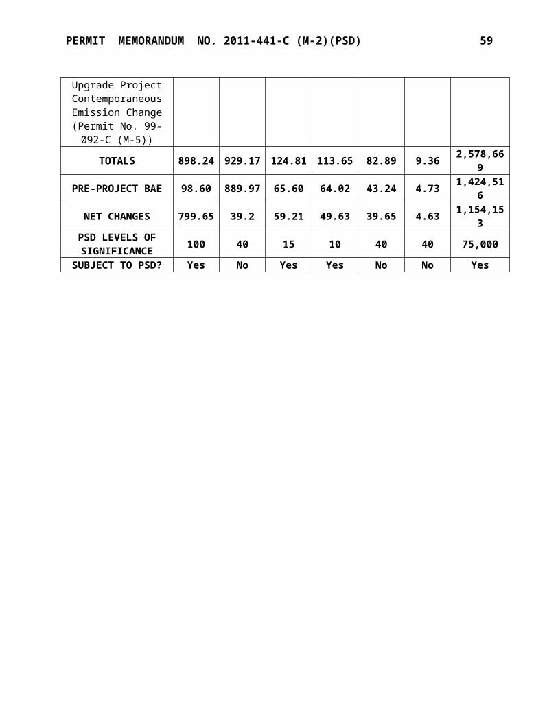
PERMIT MEMORANDUM NO. 2011-441-C (M-2)(PSD) 59
Classify the land use within the total area, Ao, circumscribed by a 3-km radius circle about the source using the meteorological land use typing scheme proposed by Auer.
If land use Types I1 (heavy industrial), I2 (light-moderate industrial), C1 (commercial), R2 (single-family compact residential), and R3 (multifamily compact residential) account for 50 percent or more of Ao, use urban dispersion coefficients; otherwise, use appropriate rural dispersion coefficients.
Based on visual inspection of the USGS 7.5-minute topographic map of the project site location, it was conservatively concluded that over 50 percent of the area surrounding the project may be classified as rural. Accordingly, the rural dispersion modeling option is used in the AERMOD PRIME model.
Significance Analysis
Dispersion modeling analysis usually involves two distinct phases; a preliminary analysis and a full impact analysis. The preliminary analysis models only the significant increase in potential emissions of a pollutant from a proposed new source, or the significant net emissions increase of a pollutant from a proposed modification. The results of this preliminary analysis determine whether the applicant must perform a full impact analysis, involving the estimation of background pollutant concentrations resulting from existing sources and growth associated with the proposed project. Specifically, the preliminary analysis:
determines whether the applicant can forego further air quality analyses for a particular pol-lutant;
may allow the applicant to be exempted from the ambient monitoring data requirements; and
is used to define the impact area within which a full impact analysis must be carried out.
In general, the full impact analysis is used to project ambient pollutant concentrations against which the applicable NAAQS and PSD increments are compared, and to assess the ambient impact of non-criteria pollutants. The full impact analysis is not required for a particular pollutant when emissions of that pollutant would not increase ambient concentrations by more than the applicable significant impact level (SIL).
Using EPA’s March 2013 “Draft Guidance for PM2.5 Permit Modeling,” a full impact analysis for PM2.5 is not required if: (1) the difference between the PM2.5 background concentration and the PM2.5 NAAQS is greater than the PM2.5 significance impact level; and (2) the modeled impacts of PM2.5 from the project would not increase ambient concentrations by more than the PM2.5 significant impact level (SIL). The same analysis was completed for CO and PM 10. As demonstrated by the following table, a full impact analysis is not required for CO, PM10, or PM2.5.

PERMIT MEMORANDUM NO. 2011-441-C (M-2)(PSD) 60
Pollutant AveragingPeriod
Max Project Impactµg/m3
SILµg/m3
Max Background
µg/m3
Background + SILµg/m3
NAAQSµg/m3
Full ImpactAnalysis
Required?
CO 1-hr 104.4 2,000 1,488 3,488 40,000 No8-hr 64.0 500 1,259 1,759 10,000 No
PM10 24-hr 4.27 5 77 82 150 No
PM2.524-hr 1.17 1.2 31 32.2 35 NoAnnual 0.23 0.3 9.7 10.0 12 No
Since the maximum project impacts are less than the PM10 24-hour, PM2.5 24-hour and PM2.5
annual Class II SILs, a full Class II increment analysis is not required.
SECTION VIII. OTHER PSD ANALYSES
A. Evaluation of Class I Area Impacts
Federally designated Class I areas are afforded special protection in the air permitting process. Generally, Class I area analyses are conducted only for projects located within 100 km of a Class I area. The Enid facility is approximately 193 km from the closest Class I area, the Wichita Mountains Wildlife Refuge. Another Class I area in proximity to the Enid facility is the Upper Buffalo Wilderness Area located in Arkansas approximately 400 km from the Enid facility.
The first step in the Class I impacts analysis is to model the project’s impacts at 50 km to determine if the project’s impacts exceed the Class I SILs. If impacts are less than the SILs, no further analysis is necessary; if they exceed the SILs, CALPUFF modeling is used to determine project impacts.
Pollutant 24-hour Average, µg/m3 Annual Averages, µg/m3
SIL Project Impacts SIL Project ImpactsPM10 0.3 0.059 0.2 0.004PM2.5 0.07 0.036 0.06 0.004CO NA NA NA NA
For the Class I area impacts analysis, the same approach was taken as for the Class II area impacts analysis. As demonstrated by the data in the following table, which uses the Class I SILs for the relevant pollutants, a full Class I area impact analysis is not required for PM10 or PM2.5:
PollutantAveragingPeriod
Max Impactµg/m3
Class I SIL
µg/m3
Max Background
µg/m3
Background + SILµg/m3
NAAQSµg/m3
Full ImpactAnalysis
Required?
PM1024-hr 0.059 0.3 77 77.3 150 NoAnnual 0.004 0.2 NA NA 50 No
PM2.524-hr 0.036 0.07 31 31.07 35 NoAnnual 0.004 0.06 9.7 9.76 12 No
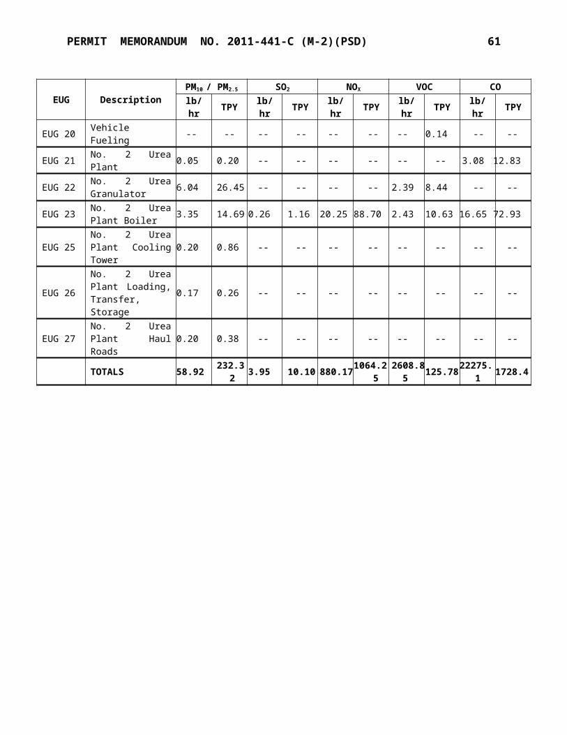
PERMIT MEMORANDUM NO. 2011-441-C (M-2)(PSD) 61
Since the maximum project impacts are less than the PM10 24-hour, PM10 annual, PM2.5 24-hour and PM2.5 annual Class I SILs, a full Class I increment analysis is not required.
A screening procedure is followed to determine potential impacts on any Air Quality Related Value (AQRV) for any Class I area within 300 km of a new source. The procedure commences with the sum of emissions of SO2, H2SO4, PM10, and NOx into the value “Q.” The Q value is then divided by the distance (D) between the source and the Class I area in question. If the Q/D ratio is less than 10, no further AQRV analysis is required. As shown in the following table, the screening criteria are met for the closest Class I area.
Class I Area Q, TPY D, km Q/D Ratio AQRV Required?
Wichita Mountains Wildlife Refuge 103.7 193 0.54 No
B. Evaluation of Source-related Impacts on Growth, Soils, Vegetation, and Visibility
Commercial, Residential, and Industrial Growth AnalysisThe project is located in Garfield County in an area zoned as industrial. Because the project will create approximately 50 additional full-time employment positions adjacent to a city of 47,000 population, the project will not have a significant effect upon the industrial growth in the immediate area. There will be an increase in the local labor force during the construction phase of the project. It is anticipated that most of the labor force during the construction phase will commute from nearby communities. This labor force increase will be temporary, short-lived, and will not result in permanent commercial and residential growth occurring in the vicinity of the project.
The potential for housing shortages and thus the possibility of housing related growth and secondary air quality impacts have been an issue historically for the construction of large plants in sparsely populated areas. However, smaller projects (modifications) like the proposed project located in or near urban areas typically have no noticeable impacts on the housing market. The reason is that impacts are primarily a function of the size of the construction workforce and the need for the workforce to relocate during construction.
The need to relocate is a function of the available workforce within a reasonable commuting distance of the work site. Research by the Electric Power Research Institute (EPRI) has indicated that the construction workforce for a power plant project can reasonably be expected to commute without relocating during construction from a distance of more than 70 miles, with instances of a commuting distance of more than 100 miles found in each of the construction projects studied. When a 70 mile radius around the Enid facility is considered, areas including Tulsa, Enid, and Ponca City in Oklahoma are within commuting distance to the site.

PERMIT MEMORANDUM NO. 2011-441-C (M-2)(PSD) 62
The area offers a wide variety of temporary lodging. Given the expected population of the commuting workforce, the fact that during the construction period most workers will be onsite for less than the total construction period, and an abundance of hotel and other short-term lodging options in Garfield County, it is unlikely that a substantial number of the construction workforce would choose to relocate during the construction period. Therefore, the anticipated housing growth will be minimal or nonexistent, and is not expected to have a significant impact on the air quality.
Population increase is a secondary growth indicator of potential increases in air quality levels. Changes in air quality due to population increase are related to the amount of vehicle traffic, commercial/institutional facilities, and home fuel use. Since there will be no or only minimal number of new, permanent jobs created by the project, secondary residential, commercial, and industrial growth is not expected to have a significant impact on the air quality.
Finally, because the maximum model-predicted CO concentrations for the proposed project are well below the NSR/PSD significant impact levels, air concentrations in the region are expected to fully comply with the ambient air quality standards when the proposed project becomes operational. Therefore, from an air quality impact standpoint, the proposed project is consistent with the balanced growth demonstrated by the county to date.
Soils & Vegetation Analyses
The NSR Workshop Manual states that the analysis of air pollution impacts on vegetation should be based on an inventory of species found in the impact area, i.e., significant impact area (SIA). Since the emissions from the proposed project did not result in any exceedances of the significant impact levels; thus no SIA exists.
Unlike fauna, CO does not poison vegetation since it is rapidly oxidized to form carbon dioxide which is used for photosynthesis. However, extremely high concentrations can reduce the photosynthetic rate. According to the USEPA document A Screening Procedure for the Impacts of Air Pollution Sources on Plant, Soils, and Animals, hereafter referred to as USEPA Screening Document, for the most sensitive vegetation, a CO concentration of 1,800,000 μg/m3 (1-week averaging period) could potentially reduce the photosynthetic rate. The maximum model-predicted 1-hour CO impact of 82.9 μg/m3 produced by the proposed project is significantly lower than this screening level (even at a conservative 1-hour averaging period). Consequently, no adverse impacts to vegetation at or near the proposed project are expected from CO emissions.
The potential effects of PM10 produced by the proposed expansion on the nearby vegetation and soil were examined. The potential effects of the air emissions to vegetation within the immediate vicinity were compared to scientific research examining the effects of pollution on vegetation. Damage to vegetation often results from acute exposure to pollution, but may also occur after prolonged or chronic exposures. Acute exposures are typically manifested by internal physical damage to leaf tissues, while chronic exposures are more associated with the inhibition of physiological processes such as photosynthesis, carbon allocation, and stomatal functioning.

PERMIT MEMORANDUM NO. 2011-441-C (M-2)(PSD) 63
The most obvious effect of particle deposition on vegetation is a physical smothering of the leaf surface. This will reduce light transmission to the plant, in turn causing a decrease in photosynthesis. Modeling results have shown that PM10 increment is still available after construction, and modeled values are almost one half less than the NAAQS level for 24-hour impacts including background. These levels are considered low, so it is highly unlikely that particulate matter emissions will impact vegetation adjacent to the Enid plant. The PM itself is agricultural fertilizer, so there should be beneficial instead of adverse impacts in the vicinity of the Enid plant.
Based upon the results, it is concluded that the construction of the proposed project will not have a significant adverse impact on the surrounding soil and vegetation.
Visibility Impairment AnalysisAn additional impacts visibility analysis may be used to determine if the emissions increases associated with a proposed PSD project will have an impact on Class I sensitive areas such as state parks, wilderness areas, or scenic sites and over looks. However, because the proposed project does not result in any increase of a visibility impairing pollutant, and because the Enid facility is not located within 40 km of a sensitive area, an additional impacts visibility impairment analysis is not required for this project. An explanation of these issues is presented in the following paragraphs.
The screening model VISCREEN can be used to perform a visibility analysis for Class II areas. The VISCREEN model uses emissions of primary particulate matter (PM), nitrogen oxides (NOX), primary nitrogen dioxide (NO2), soot (elemental carbon), and primary sulfate (SO4
-) to determine the visibility impacts from the emissions associated with the proposed project. Three screening levels for visibility impacts are recommended by EPA, for the first two of which VISCREEN is used. The first level involves conservative default parameters. If first level screening exceeds the screening levels, the analysis proceeds to a second level where low-probability events are excluded. This resulted in low wind speeds (below 1.0 m/s) and “F” stability events being excluded. The project passed Level 2 analysis.
SECTION IX. INSIGNIFICANT ACTIVITIES
The insignificant activities identified in the application submitted July 30, 2004, and listed in OAC 252:100-8, Appendix I, are summarized below. Additionally, the plant may operate sources of trivial emissions that are not required to be listed in the permit or permit application. Appropriate recordkeeping of activities indicated below with an asterisk (“*”) is specified in the Specific Conditions.
1. * Stationary reciprocating engines burning natural gas, gasoline, aircraft fuels, or diesel fuel, which are either used exclusively for emergency power generation or for peaking power service not exceeding 500 hours per year. The plant operates one (1) diesel-fired emergency generator and one (1) diesel-fired water pump, which were previously in this category but which ceased to be on the compliance date for new standards of NESHAP Subpart ZZZZ. The new emergency generator is subject to NSPS Subpart JJJJ; therefore, it does not qualify for “insignificant activity” status.
PERMIT MEMORANDUM NO. 2011-441-C (M-2)(PSD) 64
2. Various space heaters, boilers, process heaters, and emergency flares less than or equal to 5 MMBTUH heat input (commercial natural gas). In addition, the plant operates one (1) glycol dehydrator reboiler rated at 1.5 MMBTUH. Other space heaters, boilers, or process heaters may be used in the future.
3. Emissions from stationary internal combustion engines rated less than 50-hp output.
4. Gasoline and fuel handling facilities, equipment, and storage tanks except those subject to New Source Performance Standards, and standards under 252:100-37-15, 39-30, 39-41, and 39-48. None identified but may be used in the future.
5. Emissions from condensate tanks with a design capacity of 400 gallons or less in ozone attainment areas. None identified but may be used in the future.
6. * Emissions from storage tanks constructed with a capacity less than 39,894 gallons which store VOC with a vapor pressure less than 1.5 psia at maximum storage temperature. The plant operates one (1) 2,961 gallon compressor oil storage tank, one (1) 1,125 gallon diesel storage tank, one (1) 264 gallon diesel fuel tank, and one (1) 576 gallon diesel fuel tank, which are in this category. Other similar tanks may be used in the future.
7. Cold degreasing operations utilizing solvents that are denser than air. There are currently seven (7) parts washers located on-site using solvents that are denser than air, and others may be added in the future.
8. Welding and soldering operations utilizing less than 100 pounds of solder and 53 tons per year of electrode. These activities are conducted as a part of routine maintenance, which are considered trivial activities and records will not be required.
9. Hazardous waste and hazardous materials drum staging areas.
10. Sanitary sewage collection and treatment facilities other than incinerators and Publicly Owned Treatment Works (POTW). Stacks or vents for sanitary sewer plumbing traps are also included (i.e. lift station).
11. Exhaust systems for chemical, paint, and/or solvent storage rooms or cabinets, including hazardous waste satellite (accumulation) areas. The facility has exhaust systems for chemical, paint, and/or solvent storage rooms or cabinets, including hazardous waste satellite (accumulation) areas, and others may be used in the future.
12. Hand wiping and spraying of solvents from containers with less than 1 liter capacity used for spot cleaning and/or degreasing in ozone attainment areas. None identified but may be used in the future.
13. * Activities having the potential to emit no more than 5 TPY (actual) of any criteria pollutant. The plant Insignificant Activities are listed in EUG-17.
PERMIT MEMORANDUM NO. 2011-441-C (M-2)(PSD) 65
SECTION X. OKLAHOMA AIR POLLUTION CONTROL RULES
OAC 252:100-1 (General Provisions) [Applicable]Subchapter 1 includes definitions but there are no regulatory requirements.
OAC 252:100-2 (Incorporation by Reference) [Applicable]This subchapter incorporates by reference applicable provisions of Title 40 of the Code of Federal Regulations. These requirements are addressed in the “Federal Regulations” section.
OAC 252:100-3 (Air Quality Standards and Increments) [Applicable]Subchapter 3 enumerates the primary and secondary ambient air quality standards and the significant deterioration increments. At this time, all of Oklahoma is in attainment of these standards.
OAC 252:100-5 (Registration, Emission Inventory, and Annual Operating Fees) [Applicable]The owner or operator of any facility that is a source of air emissions shall submit a complete emission inventory annually on forms obtained from the Air Quality Division. Emission inventories were submitted and fees paid for previous years as required.
OAC 252:100-8 (Permits for Part 70 Sources) [Applicable]Part 5 includes the general administrative requirements for part 70 permits. Any planned changes in the operation of the facility which result in emissions not authorized in the permit and which exceed the “Insignificant Activities” or “Trivial Activities” thresholds require prior notification to AQD and may require a permit modification. Insignificant activities mean individual emission units that either are on the list in Appendix I (OAC 252:100) or whose actual calendar year emissions do not exceed the following limits:
5 TPY of any one criteria pollutant 2 TPY of any one hazardous air pollutant (HAP) or 5 TPY of multiple HAPs or 20% of any
threshold less than 10 TPY for a HAP that the EPA may establish by rule
Emission limitations for all the sources are taken from the permit application and previous per-mit.
OAC 252:100-9 (Excess Emissions Reporting Requirements) [Applicable]Except as provided in OAC 252:100-9-7(a)(1), the owner or operator of a source of excess emissions shall notify the Director as soon as possible but no later than 4:30 p.m. the following working day of the first occurrence of excess emissions in each excess emission event. No later than thirty (30) calendar days after the start of any excess emission event, the owner or operator of an air contaminant source from which excess emissions have occurred shall submit a report for each excess emission event describing the extent of the event and the actions taken by the owner or operator of the facility in response to this event. Request for affirmative defense, as described in OAC 252:100-9-8, shall be included in the excess emission event report. Additional reporting may be required in the case of ongoing emission events and in the case of excess emissions reporting required by 40 CFR Parts 60, 61, or 63.
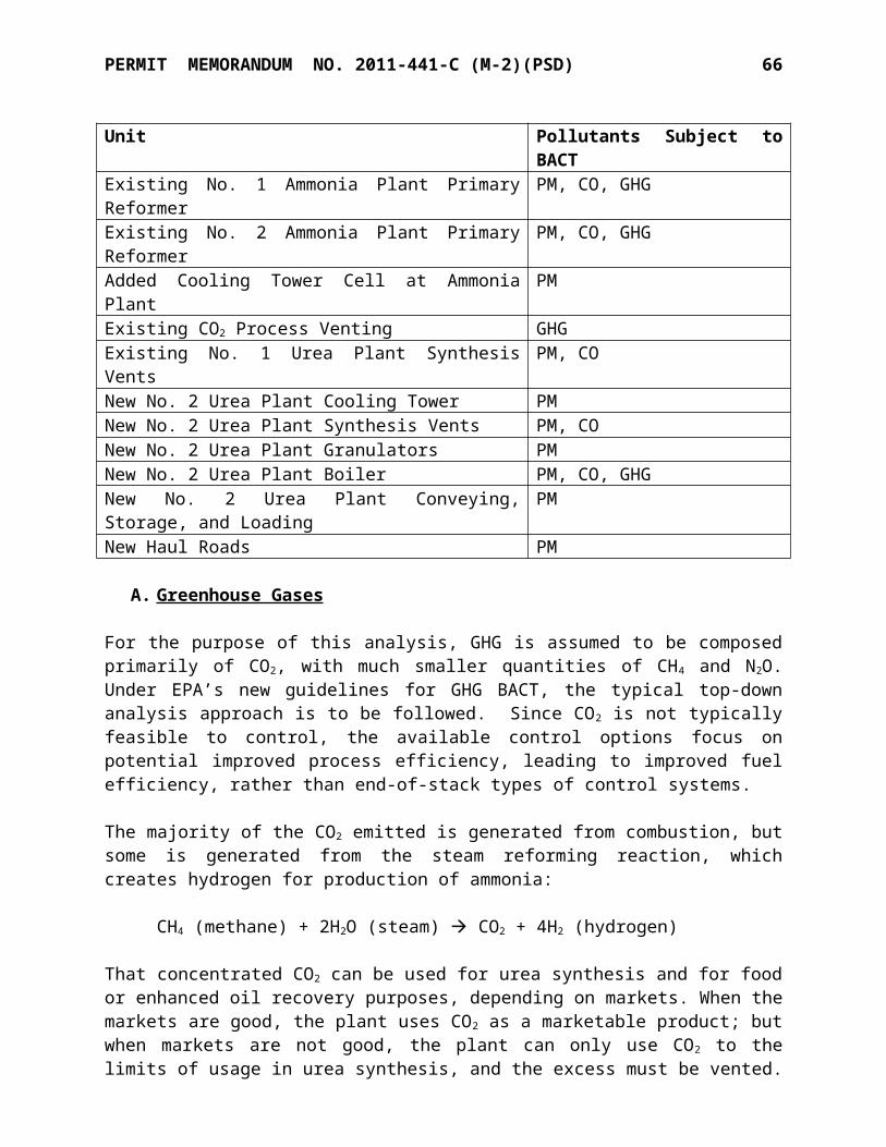
PERMIT MEMORANDUM NO. 2011-441-C (M-2)(PSD) 66
OAC 252:100-13 (Open Burning) [Applicable]Open burning of refuse and other combustible material is prohibited except as authorized in the specific examples and under the conditions listed in this subchapter. KNC on occasion conducts fire training for plant personnel. KNC notifies the local fire department of these activities prior to conducting the training.
OAC 252:100-19 (Particulate Matter) [Applicable]Section 19-12 regulates PM emissions from various industrial processes excluding indirect-fired fuel-burning units. Allowable PM emission rates are specified based on process weight rate. The following table compares process weight rate to the applicable allowable rates.
COMPARISON OF PROCESS PM EMISSIONS TO ALLOWABLE RATES OF OAC 252:100-19
Unit Process Weight Rate, TPH
Allowable PM Emission Rate of OAC 252:100-19,
lb/hr
Anticipated PM Emission Rate,
lb/hrNo. 1 Urea Granulator 1 21.53 32.06 6.60No. 1 Urea Granulator 2 21.53 32.06 6.60No. 1 Urea Granulator 3 21.53 32.06 6.60
No. 1 Urea High Pressure Urea Synthesis
Vent66.67 47.30 1.40
No. 1 Urea Low Pressure Urea Synthesis
Vent66.67 47.30 0.47
No. 2 Urea Synthesis Vent 106 51.9 0.05
No. 2 Urea Granulator 141 54.8 6.04No. 2 Urea Material
Handling 425 67.03 Negligible
No. 2 Urea Material Loading 425 67.03 Negligible
No.2 Urea Plant Loading (annual) 141 54.79 0.04
OAC 252:100-25 (Visible Emissions and Particulates) [Applicable]No discharge of greater than 20% opacity is allowed except for short-term occurrences that consist of not more than one six-minute period in any consecutive 60 minutes, not to exceed three such periods in any consecutive 24 hours. In no case shall the average of any six-minute period exceed 60% opacity. Due to the types of fuel burned (natural gas or ammonia plant purge gas) or specific process operations, the following EUGs have little potential to generate opacity (excluding steam, fog, or icy mist from the presence of uncombined water) during normal operations: EUG 2, EUG 3, EUG 4, EUG 5, EUG 7, EUG 10, EUG 13, EUG 15, EUG-17, EUG-21, EUG-22, EUG-23, EUG-25, EUG-26, and EUG-27. Therefore, specific monitoring for these sources is not necessary. Opacity requirements for sources that may have the potential to generate opacity (EUG 6, EUG 12, and EUGs 14/14A) are addressed in the specific conditions of this permit.

PERMIT MEMORANDUM NO. 2011-441-C (M-2)(PSD) 67
OAC 252:100-29 (Fugitive Dust) [Applicable]No person shall cause or permit the discharge of any visible fugitive dust emissions beyond the property line on which the emissions originate in such a manner as to damage or to interfere with the use of adjacent properties, or cause air quality standards to be exceeded, or interfere with the maintenance of air quality standards. The handling and loading of granular urea takes place within enclosed, partially-enclosed, or shrouded areas to minimize the potential for the generation of fugitive dust. Open-bodied trucks and railcars, which are used to transport urea, are covered prior to leaving the plant boundaries. Primary plant roadways are speed-controlled, paved, and maintained.
OAC 252:100-31 (Sulfur Compounds) [Applicable]Part 5 limits sulfur dioxide emissions from new fuel-burning equipment (constructed after July 1, 1972). For gaseous fuels the limit is 0.2 lb/MMBTU heat input averaged over 3 hours. For fuel gas having a gross calorific value of 1,000 BTU/SCF, this limit corresponds to fuel sulfur content of 1,203 ppmv. The permit requires the use of pipeline natural gas as defined in Part 72 having 0.5 grains TRS/100 scf to ensure compliance with Subchapter 31.
OAC 252:100-33 (Nitrogen Oxides) [Applicable]This subchapter limits new gas-fired fuel-burning equipment with rated heat input greater than or equal to 50 MMBTUH to emissions of 0.2 lb of NOx per MMBTU, three-hour average. New fuel burning equipment is defined as fuel-burning equipment that was not in service on February 14, 1972 or any existing fuel burning equipment that was altered, replaced, or rebuilt after February 14, 1972 with some exceptions. For direct fired processes, new fuel burning equipment is defined as fuel-burning equipment that was not in service on July 1, 1977 or any existing fuel burning equipment that was altered, replaced, or rebuilt after July 1, 1977, resulting in an increase in NOX emissions. The Ammonia Plant primary reformers were initially constructed in 1973 and 1975, which is in between the applicability dates for indirect fired and direct fired units. With modification and becoming subject to more stringent NOx limits, those dates are no longer significant. The following table compares NOx emissions from the plant’s fuel-burning equipment, as calculated above, to the limitations of Subchapter 33.
COMPARISON OF NOx EMISSIONS TO LIMITATIONS OF OAC 252:100-33
Unit Heat Input Capacity, MMBTUH
NOx Emission Limitation of OAC 252:100-33,
lb/MMBTU
Anticipated NOx Emission Rate,
lb/MMBTUAmmonia Plant Primary
Reformer #1 1,058 0.2 0.20
Ammonia Plant Primary Reformer #2 1,338 0.2 0.126
Ammonia Unit Startup Boiler 144 0.2 0.2
No. 1 Urea Boiler 1 84 0.2 0.2No. 1 Urea Boiler 2 84 0.2 0.2
No. 2 Urea Plt. Boiler 450 0.2 0.045
PERMIT MEMORANDUM NO. 2011-441-C (M-2)(PSD) 68
OAC 252:100-35 (Carbon Monoxide) [Not Applicable]None of the following affected processes are part of this plant: gray iron foundry, blast furnace, basic oxygen furnace, petroleum catalytic reforming unit, or petroleum catalytic cracking unit.
OAC 252:100-37 (Volatile Organic Compounds) [Applicable]Part 3 requires storage tanks constructed after December 28, 1974, with a capacity of 400 gallons or more and storing a VOC with a vapor pressure greater than 1.5 psia to be equipped with a permanent submerged fill pipe or with an organic vapor recovery system. This part applies to the 1,128 gallon gasoline storage tank, which is equipped with a permanent submerged fill pipe. The vapor pressure of diesel is less than 1.5 psia; therefore, Part 3 does not apply to the diesel tanks. The conditioning agent storage tanks (EUG 5 and EUG-24) store a VOC with a vapor pressure less than 1.5 psia; therefore, Part 3 does not apply to this unit. Ammonia is inorganic, so ammonia storage is not affected by Part 3. Part 3 requires loading facilities with a throughput equal to or less than 40,000 gallons per day to be equipped with a system for submerged filling of tank trucks or trailers if the capacity of the vehicle is greater than 200 gallons. This plant fills only vehicle gasoline tanks with capacities less than 200 gallons. Therefore, this requirement is not applicable.Part 5 limits the VOC content of coatings used in coating lines or operations. This plant will not normally conduct coating or painting operations except for routine maintenance of the plant and equipment, which is exempt.Part 7 also requires fuel-burning and refuse-burning equipment to be operated to minimize emissions of VOC. The fuel burning equipment at the plant is subject to this requirement.
OAC 252:100-42 (Toxic Air Contaminants (TAC)) [Applicable]This subchapter regulates toxic air contaminants (TAC) that are emitted into the ambient air in areas of concern (AOC). Any work practice, material substitution, or control equipment required by the Department prior to June 11, 2004, to control a TAC, shall be retained, unless a modification is approved by the Director. Since no AOC has been designated there are no specific requirements for this facility at this time.
OAC 252:100-43 (Testing, Monitoring, and Recordkeeping) [Applicable]This subchapter provides general requirements for testing, monitoring and recordkeeping and applies to any testing, monitoring or recordkeeping activity conducted at any stationary source. To determine compliance with emissions limitations or standards, the Air Quality Director may require the owner or operator of any source in the state of Oklahoma to install, maintain and operate monitoring equipment or to conduct tests, including stack tests, of the air contaminant source. All required testing must be conducted by methods approved by the Air Quality Director and under the direction of qualified personnel. A notice-of-intent to test and a testing protocol shall be submitted to Air Quality at least 30 days prior to any EPA Reference Method stack tests. Emissions and other data required to demonstrate compliance with any federal or state emission limit or standard, or any requirement set forth in a valid permit shall be recorded, maintained, and submitted as required by this subchapter, an applicable rule, or permit requirement. Data from any required testing or monitoring not conducted in accordance with the provisions of this subchapter shall be considered invalid. Nothing shall preclude the use, including the exclusive use, of any credible evidence or information relevant to whether a source would have been in compliance with applicable requirements if the appropriate performance or compliance test or procedure had been performed.

PERMIT MEMORANDUM NO. 2011-441-C (M-2)(PSD) 69
The following Oklahoma Air Pollution Control Rules are not applicable to this facility:
OAC 252:100-8 Part 9 Major Sources Affecting Nonattainment Areas not in area category
OAC 252:100-15 Mobile Sources not in source categoryOAC 252:100-17 Incinerators not type of emission unitOAC 252:100-23 Cotton Gins not type of emission unitOAC 252:100-24 Grain Elevators not in source categoryOAC 252:100-29-2 Fugitive Dust/Nonattainment Areas not in area categoryOAC 252:100-39 Nonattainment Areas not in area categoryOAC 252:100-47 Landfills not in source category
SECTION XI. FEDERAL REGULATIONS
PSD, 40 CFR Part 52 [Applicable]Emissions of several regulated pollutants exceed the major source level of 100 TPY for a listed source. PSD will apply to any future project whose added emissions exceed the significance levels: CO 100 TPY, NOX 40 TPY, SO2 40 TPY, PM 25 TPY, PM10 15 TPY, VOC 40 TPY, etc.
NSPS, 40 CFR Part 60 [Subparts Db, VVa and JJJJ Applicable]Subpart D (Steam Generating Units) regulates fossil fuel fired steam-generating units with a rated heat input above 250 MMBTUH. The auxiliary burner sections, which are used to generate steam, of the Primary Reformers (EU-101B1 and EU-101B2) are physically constrained to be less than 250 MMBTUH due to plant draft limitations. Therefore, NSPS Subpart D does not apply to EU-101B1 or EU-101B2. Subpart Db (Steam Generating Units) regulates steam-generating units rated between 100 and 250 MMBTUH that commenced construction, reconstruction, or modification after June 19, 1984. The auxiliary burner section of the Primary Reformers (EU-101B1 and EU-101B2) and the Ammonia Unit Startup Boiler (EU-2202UB) are rated at a heat input capacity greater than 100 MMBTUH. However, these units were constructed prior to the effective date of this subpart and no reconstruction has occurred, nor have any emissions increases occurred as a result of a modification. Therefore, NSPS Subpart Db is not applicable except to the new No. 2 Urea Plant boiler. Since the No. 2 Urea Plant Boiler does not burn coal or No. 2 fuel oil, it is only subject to Sections 60.44b, 60.46b, 60.48b, and 60.49b of this subpart (standards of Subpart Db for SO 2
and PM do not apply to gas-fueled boilers). Requirements include:
Compliance testing for particulate matter and nitrogen oxides (40 CFR 60.46b). The emission standard for oxides of nitrogen is 0.2 lb/MMBTU per §60.44b(a), including periods of start-up, shutdown and malfunction (§60.44b(h). Compliance with the NOX standard is to be demonstrated on a rolling 30-day basis, except that the initial performance test shall demonstrate compliance on a 24-hour basis and any subsequent performance tests shall demonstrate compliance on a 3-hour basis (§60.44b(i, j)).
Emissions monitoring for nitrogen oxides (40 CFR 60.48b). The applicant will install a continuous emission monitor (CEM) to monitor NOx on the No. 2 Urea Plant boiler.
Reporting and recordkeeping (40 CFR 60.49b). KNC will record natural gas usage and CEMs data.
PERMIT MEMORANDUM NO. 2011-441-C (M-2)(PSD) 70
Subpart Dc (Steam Generating Units) regulates steam-generating units rated between 10 and 100 MMBTUH that commenced construction, reconstruction, or modification after June 9, 1989. The Urea Boilers (EU-403A and EU-403B) are rated at a heat input capacity between 10 and 100 MMBTUH. However, these units were constructed prior to the effective date of this subpart and no reconstruction has occurred, nor have any emissions increases occurred as a result of a modification. Therefore, NSPS Subpart Dc is not applicable. Subpart G (Nitric Acid Plants) regulates nitric acid plants that commenced construction, reconstruction, or modification after August 17, 1971, but before October 14, 2011. The nitric acid plant was originally constructed in 1968 and was relocated to the current site from Kennewick, Washington in 1990. 40 CFR 60.14(e) specifically excludes a relocation or change in ownership from the definition of modification. The nitric acid plant has not been reconstructed or modified since it was originally constructed in 1968. Therefore, NSPS Subpart G does not apply.Subpart Ga (Nitric Acid Plants) regulates nitric acid plants that commenced construction, reconstruction, or modification after October 14, 2011. The nitric acid plant was originally constructed in 1968 and was relocated to the current site from Kennewick, Washington in 1990. The nitric acid plant has not been reconstructed or modified since it was originally constructed in 1968. Therefore, NSPS Subpart Ga does not apply.Subpart Kb (Volatile Organic Liquids Storage Vessels) regulates volatile organic materials storage tanks with a capacity above 19,183 gallons, which commenced construction, reconstruction, or modification after July 23, 1984. The 54,319-gallon No. 1 Urea conditioning agent storage tank (EU-D202) is above this de minimis level. However, the tank was constructed prior to 1984 and has not been reconstructed or modified since July 23, 1984. NSPS Subpart Kb applies to volatile organic materials with a vapor pressure less than 3.5 kPa (0.5 psi). The conditioning agent has a vapor pressure of approximately 2.2 kPa at the anticipated maximum monthly average temperature of 90 degrees F. Therefore, NSPS Subpart Kb does not apply.Subpart VVa (Synthetic Organic Chemical Manufacturing) is applicable. Subpart VVa affects synthetic organic chemical manufacturing operations, which commenced construction, reconstruction, or modification after November 7, 2006. Urea is a listed chemical in 40 CFR Part 60.489a. However, per 60.480a(d)(3), if a facility produces only heavy liquid chemicals from heavy liquid feed or raw materials, it is not subject to 60.482 (LDAR). The No. 1 and No. 2 Urea units will be subject only to recordkeeping and reporting requirements under 60.486a(i) and 60.487a. Subpart IIII (Stationary Compression Ignition Internal Combustion Engines) affects stationary compression ignition (CI) internal combustion engines (ICE) based on power and displacement ratings, depending on date of construction, beginning with those constructed after July 11, 2005. For the purposes of this subpart, the date that construction commences is the date the engine is ordered by the owner or operator. The existing emergency engines at this facility pre-date Subpart IIII. The emergency generator (EUG-18) is not a compression ignition engine subject to this subpart.
Subpart JJJJ, Stationary Spark Ignition Internal Combustion Engines (SI-ICE), promulgates emission standards for all new SI engines ordered after June 12, 2006, and all SI engines modified or reconstructed after June 12, 2006, regardless of size. The specific emission standards (either in g/hp-hr or as a concentration limit) vary based on engine class, engine power rating, lean-burn or rich-burn, fuel type, duty (emergency or non-emergency), and

PERMIT MEMORANDUM NO. 2011-441-C (M-2)(PSD) 71
numerous manufacture dates. Engine manufacturers are required to certify certain engines to meet the emission standards and may voluntarily certify other engines. An initial notification is required only for owners and operators of engines greater than 500 HP that are non-certified. Emergency engines will be required to be equipped with a non-resettable hour meter and are limited to 100 hours per year of operation excluding use in an emergency (the length of operation and the reason the engine was in operation must be recorded). The emergency generators in EUG-18 are subject to the applicable emission standards and all applicable testing, monitoring, recordkeeping, and reporting requirements.
NESHAP, 40 CFR Part 61 [Subparts M and FF Applicable]Subpart M (Asbestos) regulates asbestos from demolition and renovation activities. Prior to a demolition or renovation activity, owners or operators are required to inspect the affected facility or part of the facility where the renovation and demolition activity will occur for the presence of asbestos, including Category I and Category II non-friable ACM. For demolition or renovation activities subject to this subpart, owners and operators are required to comply with the standards, including notification requirements, under §61.145.Subpart FF (Benzene Waste Operations) regulates benzene contaminated wastewater at chemical manufacturing plants. The facility is not subject to control requirements of 40 CFR 61 Subpart FF because the total annual benzene quantity from facility wastewater streams is less than 1 Mg/yr. The plant is required to repeat the determination of total annual benzene quantity whenever there is a change in the process generating the waste that could cause the total annual benzene quantity to increase to 1 Mg/yr or more. The plant is also subject to recordkeeping requirements under §61.356 and reporting requirements under §61.357.
NESHAP, 40 CFR Part 63 [Subparts ZZZZ, CCCCCC, and VVVVVV Applicable]Subparts F, G, H and I (Hazardous Organic NESHAP) affect major sources of HAPs. This plant is an area source rather than a major source.Subpart FFFF (Miscellaneous Organic Chemicals) affects facilities which produce the listed or-ganic chemicals. Ammonia, nitric acid, urea, and UAN are not among the listed chemicals.Subpart ZZZZ, Reciprocating Internal Combustion Engines (RICE). This subpart previously only affected RICE with a site-rating greater than 500 brake horsepower that are located at a ma-jor source of HAP emissions. The EPA published a final rule that promulgates standards for new and reconstructed engines (after June 12, 2006) with a site rating of less than or equal to 500 HP located at major sources, and for new and reconstructed engines (after June 12, 2006) located at area sources. Owners and operators of new engines and reconstructed engines at area sources and of new or reconstructed engines with a site rating of equal to or less than 500 HP located at a ma-jor source (except new or reconstructed 4-stroke lean burn engines with a site rating of greater than or equal to 250 HP and less than or equal to 500 HP located at a major source) must meet the requirements of either 40 CFR Part 60 Subpart IIII (for CI engines) or 40 CFR Part 60 Sub-part JJJJ (for SI engines). Owners and operators of new or reconstructed 4SLB engines with a site rating of greater than or equal to 250 HP and less than or equal to 500 HP located at a major source are subject to the same MACT standards previously established for 4SLB engines above 500 HP at a major source, and must also meet the requirements of 40 CFR Part 60 Subpart JJJJ, except for the emissions standards for CO.

PERMIT MEMORANDUM NO. 2011-441-C (M-2)(PSD) 72
On March 3, 2010, EPA finalized additional requirements for stationary CI RICE located at area sources. A summary of these requirements for the emergency generator engine and fire pump engine located at this facility are shown below.

PERMIT MEMORANDUM NO. 2011-441-C (M-2)(PSD) 73
Engine Category Normal Operation @ 15% O2
Existing Emergency CI & Black Start CI
Change oil and filter every 500 hours of operation or annually, whichever one comes first;Inspect air cleaner every 1,000 hours of operation or annually, whichever one comes first; andInspect all hoses and belts every 500 hours of operation or annually, whichever one comes first and replace as necessary.
Sources have the option to utilize an oil analysis program in order to extend the specified oil change requirements of this subpart. Initial compliance demonstrations must be conducted within 180 days after the compliance date. Owners and operators of a non-operational engine can conduct the performance test when the engine is started up again.
Other applicable requirements include:1) The owner/operator must operate and maintain the stationary RICE and after-treatment
control device (if any) according to the manufacturer’s emission-related written instructions or develop their own maintenance plan which must provide to the extent practicable for the maintenance and operation of the engine in a manner consistent with good air pollution control practice for minimizing emissions.
2) Existing emergency stationary RICE located at an area source of HAP emissions must install a non-resettable hour meter if one is not already installed.
Existing stationary CI RICE (EUG-19) located at an area source of HAP emissions must comply with the applicable emission limitations and operating limitations no later than May 3, 2013. The permit will require the facility to comply with all applicable requirements.
Subpart DDDDD, National Emission Standards for Hazardous Air Pollutants for Industrial, Commercial and Institutional Boilers and Process Heaters at major sources of HAPs. This facility is an “area” source of HAPs.
Subpart CCCCCC, Gasoline Dispensing Facilities. This subpart establishes emission limitations and management practices for HAP emitted from the loading of gasoline storage tanks at gasoline dispensing facilities (GDF) located at an area source. GDF means any stationary facility which dispenses gasoline into the fuel tank of a motor vehicle. The affected source includes each gasoline cargo tank during the delivery of product to a GDF and also includes each storage tank. This regulation applies to EUG 20.If a GDF has a monthly throughput of less than 10,000 gallons of gasoline, the operator must not allow gasoline to be handled in a manner that would result in vapor releases to the atmosphere for extended periods of time. Measures to be taken include, but are not limited to, the following:1) Minimize gasoline spills;2) Clean up spills as expeditiously as practicable;3) Cover all open gasoline containers and all gasoline storage tank fill-pipes with a gasketed
seal when not in use;4) Minimize gasoline sent to open waste collection systems that collect and transport gasoline
to reclamation and recycling devices, such as oil/water separators.

PERMIT MEMORANDUM NO. 2011-441-C (M-2)(PSD) 74
Subpart JJJJJJ, Industrial, Commercial, and Institutional Boilers. This subpart affects new and existing boilers located at area sources of HAP, except for gas-fired boilers. Gas fired boilers are defined as any boiler that burns gaseous fuel not combined with any solid fuels, liquid fuel only during periods of gas curtailment, gas supply emergencies, or periodic testing on liquid fuel. The boilers and auxiliary boilers at this facility meet the definition of gas fired boilers and are not subject to this subpart. Process heaters such as the Ammonia Reformers are not regulated by Subpart JJJJJJ. Therefore, this regulation does not apply to the Enid site.Subpart VVVVVV, Chemical Manufacturing Area Sources. This subpart affects each chemical manufacturing process unit that uses as feedstocks or generates as products or byproducts any of the listed organic or metal HAPs. The compliance date for Subpart VVVVVV is October 29, 2012. The facility does not produce any organic HAP is Table 1 of Subpart VVVVVV, but does have nickel and chromium as components of catalysts. Therefore, Subpart VVVVVV does apply to the site.
Compliance Assurance Monitoring, 40 CFR Part 64 [Applicable]Compliance Assurance Monitoring, as published in the Federal Register on October 22, 1997, applies to any pollutant specific emission unit at a major source that is required to obtain a Title V permit. 40 CFR 64.5(b) requires the owner or operator to submit a CAM plan (if applicable) as part of the application for the renewal for a Part 70 permit. The Nitric Acid Plant stack is subject to emission limitations in this permit and is equipped with a non-selective catalytic reduction system, which reduces emissions of nitrogen oxides (NOX). KNC is required by this permit to operate a continuous emissions monitoring system (CEMS) to record emissions of NOX
from the Nitric Acid Plant stack on a continuous basis. In accordance with 40 CFR 64.2(b)(vi), CAM requirements do not apply to units equipped with a permit-required CEMS. CAM for the urea granulators will be required for permit renewal.
Chemical Accident Prevention Provisions, 40 CFR Part 68 [Applicable]The plant has substances regulated under 40 CFR Part 68 present in quantities greater than the threshold quantities; therefore, 40 CFR Part 68 is applicable. A Risk Management Plan was submitted on June 16, 1999, and determined to be complete by EPA. KNC has prepared the plant’s updated RMP and it was submitted by the June 21, 2004 deadline. KNC is in compliance with requirements of this part, including registration and submission of an RMP. More information on this federal program is available on the web page: www.epa.gov/ceppo.
Stratospheric Ozone Protection, 40 CFR Part 82 [Subpart A and F Applicable]These standards require phase out of Class I & II substances, reductions of emissions of Class I & II substances to the lowest achievable level in all use sectors, and banning use of nonessential products containing ozone-depleting substances (Subparts A & C); control servicing of motor vehicle air conditioners (Subpart B); require Federal agencies to adopt procurement regulations which meet phase out requirements and which maximize the substitution of safe alternatives to Class I and Class II substances (Subpart D); require warning labels on products made with or containing Class I or II substances (Subpart E); maximize the use of recycling and recovery upon disposal (Subpart F); require producers to identify substitutes for ozone-depleting compounds under the Significant New Alternatives Program (Subpart G); and reduce the emissions of halons (Subpart H).

PERMIT MEMORANDUM NO. 2011-441-C (M-2)(PSD) 75
Subpart A identifies ozone-depleting substances and divides them into two classes. Class I controlled substances are divided into seven groups; the chemicals typically used by the manufacturing industry include carbon tetrachloride (Class I, Group IV) and methyl chloroform (Class I, Group V). A complete phase-out of production of Class I substances is required by January 1, 2000 (January 1, 2002, for methyl chloroform). Class II chemicals, which are hydrochlorofluorocarbons (HCFCs), are generally seen as interim substitutes for Class I CFCs. Class II substances consist of 33 HCFCs. A complete phase-out of Class II substances, scheduled in phases starting by 2002, is required by January 1, 2030. This facility does not utilize any Class I & II substances.
SECTION XII. COMPLIANCE
Tier Classification and Public Review
This application has been determined to be a Tier II because it is a construction permit for a sig-nificant modification to a Title V source.
The applicant published the “Notice of Filing a Tier II Application” in the Enid News and Eagle, a daily newspaper circulated in Garfield County, on November 27, 2013. The notice stated that the application was available for public review at the Enid Public Library, 120 West Maine Ave, Enid, OK or at the DEQ Air Quality Office in Oklahoma City. A draft of this permit was also made available for public review for a period of thirty days as stated in another newspaper announcement in the Enid News and Eagle on April 4, 2014. The applicant has requested that the public review period and EPA’s review run concurrently. The facility is located within 50 miles of the border with the state of Kansas; that state was notified of the draft permit. No comments were received from the public or adjacent state.
On May 2, 2014, Mr. Dinesh Senghani of EPA Region VI Air Permits Section provided the following comments (comments have been reproduced exactly as made):
1. Please explain how the net change of GHG emissions of 1,549,793 tpy given on page 30 was obtained when the baseline emissions for Pre-Project given on page 29 is 1,424,516 tpy and the potential emissions for Post-Project given on page 30 is 2,578,669 tpy giving a difference between for Post-Project potential and Pre-Project baseline emissions is 1,154,153 tpy. We also noticed errors in calculations for net changes for other criteria pollutants emissions in the same table.
EPA is correct that the net emissions change should be stated as “1,154,153” TPY, and the evaluation will be edited accordingly. The application had several revisions following initial submittal, and not all changes were caught in the final version. The emissions change totals have been revised as needed.
2. Page 18 states that the “Potential Process CO2 Generation” of the “physical modified equipment” the two Ammonia Plants is 1,655,639, but the “Potential to emit” is limited to 1,260,000 tpy “based on the maximum expected process CO2 emission rate of 1.26 tons CO2/ton of Ammonia generated”.
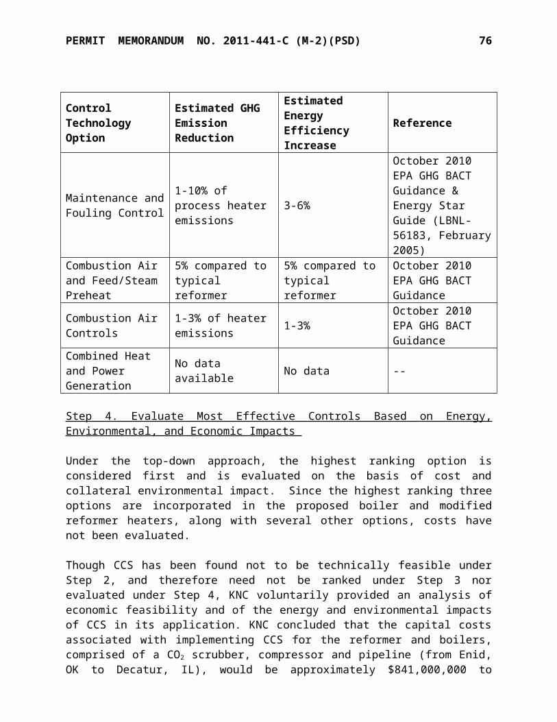
PERMIT MEMORANDUM NO. 2011-441-C (M-2)(PSD) 76
There appears to have been some confusion created from listing both the potential CO2
generation and the artificially-limited CO2 generation in the same table. The footnote to that table, “Based on emission rate of 1.26 tons CO2 / ton ammonia where the potential to emit is limited by permit condition,” should adequately clarify that 1,260,000 TPY is an artificial limit.
a. Please explain how and what process control parameters will be used to achieve this limitation of CO2 emissions during regular production.
The amount of CO2 generated in the ammonia units will be calculated using the 40 CFR 98, Subpart G data and method. CO2 is used for urea synthesis as a raw material and is a salable product. The plant uses flow meters to monitor the amount of CO2 going to internal urea production and to outside sales. Because there is no CO2 storage capacity at the facility, the amount of CO2 vented—up to the annual limit established by the permit—will be calculated and reported as the difference between the amount of CO2 generated and the sum of the amounts accounted for in urea production and outside sales. These monitoring, recordkeeping, and reporting requirements are adequate to verify compliance with the proposed 1,260,000 TPY permit limit.
b. If no process control parameters are used and only a “mass balance approach” is used as specified on page 76 will production be stopped when the process CO2
emission rate of 1,260,000 tpy is reached during the production year?
The permit establishes a clear legal obligation for the facility to prevent Process CO2 emissions above the permit limit of 1,260,000 TPY. The permittee will monitor its emissions to verify compliance with the limit on a rolling monthly basis. As with any annual emission limit, the permittee will need to comply with the limit and would need to adjust operation, including ceasing production if necessary, to avoid exceeding the limit within a rolling 12-month period.
c. Please explain whether the calculations specified in paragraph C.1 on page 76 is carried out automatically on a continuous basis to determine the limits of 1.26 tons CO2/ton of Ammonia generated and the process CO2 emission rate of 1,260,000 tpy 12 month rolling average.
Process CO2 generation and the flows to internal use and external sales are collected automatically using flow meters and the data is aggregated monthly. The 12-month rolling averages of CO2 emissions will be calculated using this data to determine compliance with the 1,260,000 TPY and the 1.26 ton CO2/ton ammonia limits.
d. Please explain how the emission limits quoted in [c] above are enforced if calculations are carried out on a monthly basis as specified in page 95 Specific Conditions sections Z-AA and Z-BB.
Under the permit, records are required to be kept for Ammonia production (5.Z), Process CO2
generation (5.AA) and internal CO2 usage and sales (5.BB) on a monthly basis. The CO2
emission limits are to be enforced on a 12-month rolling average basis. The annual limit rolled monthly is adequate to ensure enforceability of the limit; doing calculations more frequently is not appropriate since there is no shorter-term standard to compare emissions to.
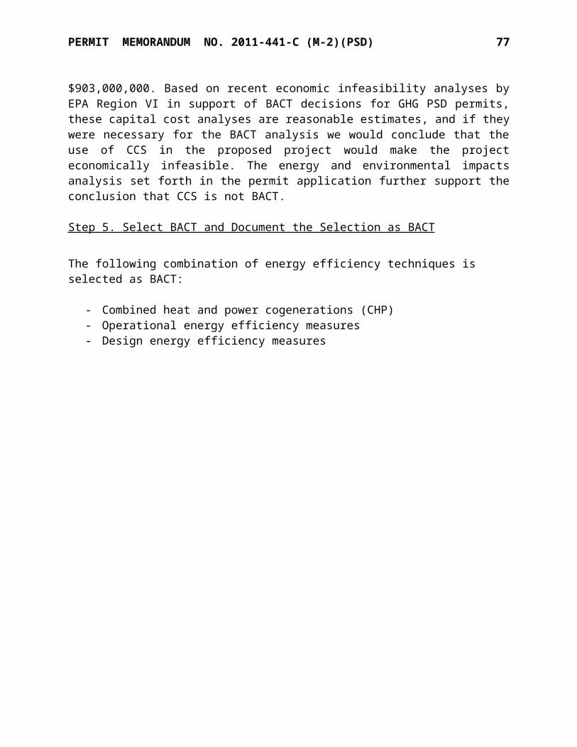
PERMIT MEMORANDUM NO. 2011-441-C (M-2)(PSD) 77
3. Under the definition of “Subject to regulation” in the greenhouse gas (“GHG”) tailoring rule at 40 CFR 51.21, and under the definition of “Regulated NSR pollutant” at 40 CFR 52.21(b)(60)(iv), the pollutant that is subject to regulation, and therefore a regulated NSR pollutant, is defined as GHG, not carbon dioxide “CO2”). Therefore, the BACT emissions limit should be expressed in terms of total GHG emissions, as CO2-equivalent (“CO2e”), and the permit should indicate how compliance will be demonstrated for the two non-CO2 GHGs to be emitted. ODEQ should provide any technical documentation supporting facts in its permit memorandum for its BACT analysis for methane (CH4) and nitrous oxide (N2O).
References to “CO2” under the Plant-Wide requirements will be edited to “CO2e.” Compliance with CO2e emission limits for combustion sources (including CH4 and N2O components) will be demonstrated using 40 CFR 98, Subpart C as described in Section 1.D.1 of the Specific Conditions. Compliance with CO2e emission limits for process units will be demonstrated as described in Specific Conditions 1.C.1 and 1.C.2 using the emission calculation method of 40 CFR 98, Subpart G. This method assumes that all carbon in the ammonia unit feedstock is fully oxidized to CO2. With respect to N2O, none of EPA’s technical documents on ammonia manufacturing suggest that N2O is produced through the ammonia synthesis process. We have concluded—like EPA did in developing the 40 CFR 98 Subpart G requirements—that CH4 and N2O from ammonia manufacturing do not warrant monitoring, recordkeeping, or reporting, nor do they contribute to the overall CO2e process emissions from the facility.
4. The global warming potentials (GWP) have been revised by EPA. The final rule published on November 29, 2013 in the Federal Register will be effective for all permits issued on or after January 1, 2014. The methane value was increased from 21 to 25 (times more potent than CO2), and the N2O value was decreased from 310 to 298. Due to the prospective changes in the emissions for methane and N2O, please provide an updated emission tables using the new GWPs to reflect correct emissions in the permit.
The emissions calculations were updated in January 2014 to include the new GWP factors and are reflected in the permit limits. No corrections on the proposed permit are needed.
5. ODEQ selected “Good combustion practices”, “Good design practices” and “good operating practices” as BACT and lowest achievable emissions rate for various pollutants on various sources in the PSD permit. “Good combustion practices”, “Good design practices” and “good operating practices” however, are not defined in the permit records. ODEQ should include a description of the various practices that will be required for each pollutant on each source and must incorporate them into the PSD permit.
Good combustion practices and designs involve combustion units which promote turbulent mixing and maintain sufficient oxygen and temperature to achieve essentially complete combustion of fuels. While excess air may be desirable for complete combustion, the additional mass lowers the operating temperature in the flame zone. (It should be noted that lower operating temperatures which retard NOx formation could increase CO and VOC emissions.) A well-designed and operated unit will have monitoring of fuel and air supply mechanisms to ensure that optimal conditions are maintained across a range of operating conditions.

PERMIT MEMORANDUM NO. 2011-441-C (M-2)(PSD) 78
The plant has an economic incentive to design and operate equipment which uses only as much fuel as is needed to provide energy to the processes rather than just creating hot exhausts, therefore, specific measures are rarely stated in permits. These BACT conditions are verified by stack testing of CO and VOC concentrations in exhausts.
6. On page 30, the draft PSD permit provides net emissions changes for NOx and VOC emissions for the project 39.30 tpy and 39.64 tpy respectively. These net emissions changes are just below the PSD levels of significance or significant emissions rates (SERs) threshold. If NOx and VOC emissions are not precisely measured during all operating time, including startup and shutdown, these limits are highly suspect.
For the NOx sources, the new boiler will be continuously monitored for NOx, and the reformers are already subject to periodic testing requirements. For VOC, the new sources with noticeable VOC are the boiler and the new urea plant. Testing for VOC will be added to the permit requirements for the new boiler and urea plant.
ODEQ has the discretion to make a case-by-case determination of reasonable methods to determine compliance. Should ODEQ become concerned about the emission estimates in the future, has the ability to require stack testing at any point.
The applicant has submitted an affidavit that they are not seeking a permit for land use or for any operation upon land owned by others without their knowledge. The affidavit certifies that the applicant owns the property or has provided appropriate notification.
Information on all permit actions is available for review by the public in the Air Quality section of the DEQ Web page: http://www.deq.state.ok.us/
Fees Paid
Major source construction permit fee of $5,000.
SECTION XIII. SUMMARY
The facility has demonstrated the ability to comply with the requirements of the several air pollu-tion control rules and regulations. Ambient air quality standards are not threatened at this site. Issuance of the permit is recommended.

PERMIT TO CONSTRUCTAIR POLLUTION CONTROL FACILITY
SPECIFIC CONDITIONS
Koch Nitrogen Company Permit No. 2011-441-C (M-2)(PSD)Enid Nitrogen Plant
The permittee is authorized to construct in conformity with the specifications submitted to Air Quality on November 21, 2013. The Evaluation Memorandum dated May 27, 2014, explains the derivation of applicable permit requirements and estimates of emissions; however, it does not contain limitations or permit requirements. Commencing construction or continuing operations under this permit constitutes acceptance of, and consent to the conditions contained herein.
1. Point of emissions and applicable emissions limitations. [OAC 252:100-8-6(a)(1)]
EUG 1 Plant-wide Emissions Cap
A. The permittee shall limit actual annual emissions of methanol from the plant to 9.9 TPY (calculated on a 12-month rolling total). Actual annual plant-wide methanol emissions shall be calculated each month and the 12-month rolling total shall be de-termined. Relevant records specified in Specific Condition 5 will be used in the methanol emission calculations, as applicable.
B. The permittee shall tabulate monthly methanol emissions using the methods outlined below or based on equivalent methods as accepted by ODEQ.
1. Emissions from methanol-containing conditioning agent(s) shall be calculated on a mass balance basis from the weight of conditioning agent(s) added to urea from each urea plant times the weight percent of methanol in the condi-tioning agent(s). The average weight percent of methanol in the conditioning agent(s) shall be based on a 12-month rolling average calculated for each granular urea plant.
2. Emissions from diverting process condensate from the process condensate stripper to the zero discharge pond or emergency venting from the process condensate stripper stack to the atmosphere, shall be calculated based on the methanol concentrations in the condensate times the volume of condensate di-verted to the ponds and/or the methanol concentrations exhausted to the at-mosphere.
3. Methanol emissions during plant startup, shutdown, and/or malfunction events from each of the CO2 strippers (PIC-30 vents) shall be calculated as 0.476 lb methanol per ton CO2 or based on factors derived for each PIC-30 vent from the most recent ODEQ-approved stack test.
C. Facility-wide process CO2 emissions shall not exceed 1,260,000 tons per year, 12-month rolling average.

SPECIFIC CONDITIONS NO. 2011-441-C (M-2)(PSD) 2
1. Facility-wide process CO2e emissions shall not exceed 1,260,000 tons per year, 12month rolling average. Compliance with this limit will be demonstrated using 40 CFR 98, Subpart G to calculate the amount of process CO2 produced plant-wide, then subtracting the amount of CO2 sold or consumed plant-wide using a mass balance approach. Relevant records specified in Specific Condition 5 will be used in the CO2 emission calculations, as applicable.
2. Plant-wide process CO2 emissions shall not exceed a rate of 1.26 tons CO2e emitted per ton ammonia produced on 12-month rolling average. Compliance with this limit will be demonstrated using the procedure in paragraph C.1 to calculate plant-wide CO2e emissions and site production records to calculate the amount of ammonia produced plant-wide.
D. The permittee shall limit combustion CO2e as follows: 1. Total combustion CO2e emissions from the emission unit groups EUG 2,
EUG 3 (except this limit does not apply to 2202UB), and EUG 23, shall not exceed 1,318,669 tons per year on a 12-month rolling average. Compliance with this limit will be demonstrated using 40 CFR 98, Subpart C to calculate combustion CO2 from these emission unit groups.
2. Combustion CO2 emissions from the emission unit groups: EUG 2, EUG 3 (except this limit does not apply to 2202UB), and EUG 23, shall not exceed 117 lb/MMBtu. Compliance with this limit will be demonstrated using records of fuel consumed.
3. Compliance Demonstration: Use of pipeline-quality natural gas as the only fuel demonstrates compliance with combustion CO2e emissions limitations for EUG 2, EUG 3, and EUG 23. Compliance can be shown by the following methods: for pipeline grade natural gas, a current gas company bill. Compliance shall be demonstrated at least once annually.
EUG 2 Ammonia Plant Primary Reformers
Location EU ID Heat Input*Ammonia Plant #1 101B1 965 MMBTUHAmmonia Plant #2 101B2 990 MMBTUH
*Heat input limitation is for a 12-month rolling averaging period, and includes arch burners, tunnel burners, superheat burners, and auxiliary boiler burners.
Point ID EmissionUnit
PM10 / PM2.5 SO2 NOx VOC COlb/hr TPY lb/hr TPY lb/hr TPY lb/hr TPY lb/hr TPY
2-9095 (No. 1
Reformer)
101B1 7.88 31.49 0.93 3.73 211.60 500.86 7.13 28.49 87.13 348.08
2-9097 (No. 2
Reformer)
101B2 9.97 32.31 1.18 3.83 168.59 173.45 9.02 29.23 110.19 357.10

SPECIFIC CONDITIONS NO. 2011-441-C (M-2)(PSD) 3
A. The above fuel-burning equipment shall be fueled by pipeline quality natural gas and ammonia and HRU plant purge gas as primary fuels.
B. Emissions of NOx from the No. 1 Reformer shall not exceed 0.12 lb/MMBTU, annual average, or 0.20 lb/MMBTU, 3-hour average. [OAC 252:100-33]
C. Emissions of NOx from the No. 2 Reformer shall not exceed 0.040 lb/MMBTU, annual average, or 0.126 lb/MMBTU, 3-hour average. [OAC 252:100-33]
D. Within 180 days following completion of physical modifications to the each reformer’s heaters, performance testing shall be conducted and a written report of results submitted to AQD. The following USEPA methods shall be used for testing of emissions, unless otherwise approved by Air Quality:
Method 1: Sample and Velocity Traverses for Stationary Sources.Method 2: Determination of Stack Gas Velocity and Volumetric Flow Rate.Method 3: Gas Analysis for Carbon Dioxide, Excess Air, and Dry Molecular
Weight.Method 4: Moisture in Stack Gases.Method 7E: NOx Emissions from Stationary SourcesMethod 10: Carbon Monoxide Emissions from Stationary Sources
E. A copy of the test plan shall be provided to AQD at least 30 days prior to each test date.
F. Performance testing shall be conducted while the units are operating within 10% of the rates at which operating permit authorization will be sought.
G. At least 30 days prior to the testing, a notification of the test date and testing protocol shall be submitted to AQD. Deficiencies in the protocol shall be resolved prior to commencement of testing.
H. Combustion CO2e emissions shall not exceed 117 lb CO2e / MMBTU heat input (30 day rolling average). [OAC 252:100-8-34(b)]
I. Prior to commencement of operations of the new boiler in EUG-23, the No. 2 Reformer shall include a selective catalytic reduction system which achieves NOx emissions of 0.04 lb/MMBTU or less. [OAC 252:100-8-5]
J. Emissions of NOx from the No. 2 Reformer shall be monitored using a continuous emissions monitoring system. The CEMS shall be installed and certified within 180 days following the modifications in this permit. [OAC 252:100-43]
K. The following requirements demonstrate compliance with the heat input restrictions for EUG 2 and with the lb/hr and ton/year limitations for EUG 2. [OAC 252:100-43]
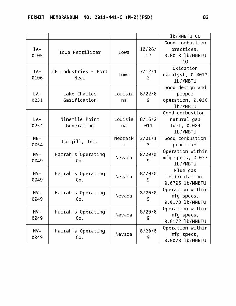
SPECIFIC CONDITIONS NO. 2011-441-C (M-2)(PSD) 4
1. The permittee shall measure natural gas and ammonia plant purge gas flow to the primary reformers. Flow instrumentation shall be calibrated semi-annually.
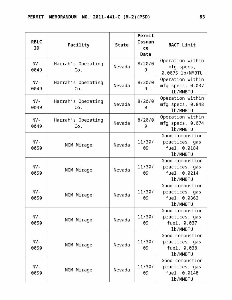
SPECIFIC CONDITIONS NO. 2011-441-C (M-2)(PSD) 5
2. The permittee shall calculate the total fuel energy usage in each plant by adding the total natural gas energy for fuel to the purge gas energy usage for fuel for each plant.
3. The permittee shall calculate the average hourly heat input for each plant by dividing the total plant fuel energy usage by the number of hours the plant operated during the month. Monthly calculations shall be used to determine the heat input on a 12-month rolling average.
L. Compliance with the hourly emission rates for the Reformers shall be determined by multiplying the 3-hour average heat input rate by the 3-hour average CEMs emissions rate (lb/MMBTU) or the most recent stack testing factor for NOx and CO, and AP-42 factors for VOC, SO2, and PM as applicable.
M. During periods of start-up and shutdown not to exceed 6 hours for each start-up/shutdown event, NOx emissions from the No. 2 Reformer may be up to 0.2 lb/MMBTU.
EUG 3 Heaters/Boilers > 50 MMBTUH
Location EU ID EU Name/ModelAmmonia Plant #1 2202UB Ammonia Unit Startup BoilerNo. 1 Urea Plant 403A No. 1 Urea Boiler No. 1No. 1 Urea Plant 403B No. 1 Urea Boiler No. 2
Point ID
EmissionUnit
PM10 SO2 NOx VOC COlb/hr TPY lb/hr TPY lb/hr TPY lb/hr TPY lb/hr TPY
3-9099 2202UB 1.6 3.5 0.1 0.2 28.8 63.0 1.2 2.6 17.8 39.03-9100 403A 0.94 4.11 0.07 0.32 16.80 73.58 0.68 2.98 10.38 45.453-9101 403B 0.94 4.11 0.07 0.32 16.80 73.58 0.68 2.98 10.38 45.45
All emissions limits on a TPY basis are on a 12-month rolling basis.
A. The fuel-burning equipment shall be fired with pipeline grade natural gas.
B. Emissions of nitrogen oxides from the fuel burning equipment shall not exceed 0.2 lb/MMBTU, three hour average. [OAC 252:100-33-2(a)]
C. Operation of EU 2202UB is limited to 4,380 hours per year annual operation.
D. Compliance Demonstration: Use of pipeline-quality natural gas as the only fuel and having hours of operation less than or equal to 4,380 hours per year (12-month rolling total) for EU 2202UB demonstrates compliance with the lb/hr and TPY emissions limitations for EUG 3. Compliance can be shown by the following methods: for pipeline grade natural gas, a current gas company bill. Compliance shall be demonstrated at least once annually.

SPECIFIC CONDITIONS NO. 2011-441-C (M-2)(PSD) 6
EUG 4 Heaters/Boilers < 50 MMBTUH
Location EU ID EU Name/ModelAmmonia Plant #1 102B1 Ammonia Unit Startup Heater No. 1Ammonia Plant #2 102B2 Ammonia Unit Startup Heater No. 2
Point ID
EmissionUnit
PM10 SO2 NOx VOC COlb/hr TPY lb/hr TPY lb/hr TPY lb/hr TPY lb/hr TPY
4-9102 102B1 0.4 1.6 0.03 0.1 4.9 21.3 0.3 1.2 4.1 17.94-9103 102B2 0.4 1.6 0.03 0.1 4.9 21.3 0.3 1.2 4.1 17.9
A. The fuel-burning equipment shall be fired with pipeline grade natural gas.
B. Compliance Demonstration: Use of pipeline-quality natural gas as the only fuel demonstrates compliance with emissions limitations for EUG 4. Compliance can be shown by the following methods: for pipeline grade natural gas, a current gas company bill. Compliance shall be demonstrated at least once annually.
EUG 5 No. 1 Urea Plant Conditioning Agent Storage Tank: The equipment item listed below is considered insignificant.
Location EU ID EU NameNo. 1 Urea Plant D202 Conditioning Agent Tank
A. Methanol emission limitations and compliance demonstration for this source are addressed in Item A for EUG 1.
EUG 6 No. 1 Urea Plant Granulators
Point ID
EmissionUnit
PM10
lb/hr TPY6-9104 Granulator 1 6.60 28.926-9105 Granulator 2 6.60 28.926-9106 Granulator 3 6.60 28.92
A. Compliance Demonstration: Visible emissions observations shall be performed at least monthly during normal plant operations by conducting a plant walkthrough for sources categorized under EUG 6. A record shall be maintained indicating if any opacity or visible emissions (excluding steam, fog, or icy mist from the presence of uncombined water) were observed during the monthly observations. If visible emis-sions are detected during normal operations, corrective action shall be taken as soon as possible and/or a six-minute opacity reading in accordance with EPA Reference Method #9 (RM 9) will be conducted within three (3) working days.
[OAC 252:100-25-3(b)]
SPECIFIC CONDITIONS NO. 2011-441-C (M-2)(PSD) 7
B. All discharges from each urea granulation operation shall be processed by a high-effi-ciency spray tower wet scrubber or equivalent device for PM emissions control.
[OAC 252:100-8-34(b)(1)]
C. Each scrubber shall be operated with a pressure differential of at least 7 inches WC when processing discharges from each urea plant granulator stack. The pressure dif-ferential from each scrubber shall be monitored and recorded at least once daily when operating. If the pressure differential is found to be less than 7 inches WC, corrective action shall be taken within four (4) hours and another reading taken. If two (2) con-secutive readings are found to be out of range, a possible deviation may have oc-curred and the permittee shall include such event in the Title V Semi-Annual Moni-toring and Deviation Report. [OAC 252:100-43]
D. The permittee is subject to following requirements under 40 CFR 60, Subpart VVa for the urea plant, as applicable:
i. 60.486a: Recordkeeping requirementsii. 60.487a. Reporting requirements
EUG 7 No. 1 Urea Plant Synthesis Vents
Point ID EmissionUnit
CO PM10
lb/hr TPY lb/hr TPY7-9111 No. 1 Urea High
Pressure Vent 3.86 16.40 1.87 7.927-9110 No. 1 Urea Low Pressure Vent
A. Compliance Demonstration: Compliance with these limits is demonstrated by Urea production of 1,550 TPD (monthly average) or less.
EUG 9: No. 2 Ammonia Plant Cooling Tower
Point ID
EmissionUnit
PM10 PM2.5 NOx VOC COlb/hr TPY lb/hr TPY lb/hr TPY lb/hr TPY lb/hr TPY
9-9159
No. 2 Ammonia
Plant Cooling Tower
0.46 2.02 0.002 0.009 -- -- -- -- -- --
A. Compliance Demonstrations: the following records shall be kept for the No. 2 Ammonia Plant Cooling Tower: [OAC 252:100-43]
i. Records of vendor certification of maximum circulation rateii. Records of design and construction showing 0.0005% or better drift, on the added
cell. iii. Records of TDS content of cooling water, tested within 180 days of start-up.
SPECIFIC CONDITIONS NO. 2011-441-C (M-2)(PSD) 8
EUG 10 CO2 Stripping Towers:
Point ID Emission Unit COlb/hr TPY
10-9120 CO2 Stripping Tower 1 5.8 25.410-9121 CO2 Stripping Tower 2 5.8 25.4
All emissions limits on a TPY basis are on a 12-month rolling basis.
A. The permittee shall maintain logs of the duration (hours) of venting to the atmosphere. [OAC 252:100-43]
B. Excess emissions resulting from unanticipated events, such as malfunctions, shall be reported consistent with 252:100-5 and 252:100-9.
EUG 11 Nitric Acid Plant:
Point ID Emission Unit NOX
ppm* lb/hr TPY
12-9115 Nitric Acid Plant – Normal Operation 79 5.0 21.9Nitric Acid Plant – Start-up and Shutdown 750 47.5 3.6
*based upon a 3-hour averaging period using the arithmetic average from three contiguous 1-hour periods. All emissions limits on a TPY basis are on a 12-month rolling basis.
A. Air emissions from the nitric acid plant shall be processed by an abatement system that reduces NOX emissions to 79 ppmdv or less, based on a 3-hour averaging period using the arithmetic average from three contiguous one-hour periods. The permittee shall maintain compliance with the NOX limits at all times, except as specified in Condition F below.
B. The permittee shall operate and maintain a continuous emission monitoring system (CEMS) for measuring nitrogen oxides. Except for periods of system breakdowns, repairs, calibration checks, and zero and span adjustments not to exceed a total of 2.5% of the operating hours in a calendar quarter, the CEMS shall be in continuous operation. [OAC 252:100-43]
C. A record shall be maintained of emissions resulting from start-up, shutdown, and malfunction events and the duration of each occurrence. Emissions resulting from start-up, shutdown and malfunction events shall be quantified for this source and reported in the facility’s annual emissions inventory.
D. When monitoring shows concentrations in excess of the ppm limit for either normal operations (79 ppm) or for start-ups and shutdowns (750 ppm), the owner or operator shall comply with reporting provisions of OAC 252:100-9-3 for excess emissions. Requirements for periods of other excess emissions (during normal operations) include prompt notification to Air Quality and prompt commencement of repairs to correct the condition of excess emissions. [OAC 252:100-9]

SPECIFIC CONDITIONS NO. 2011-441-C (M-2)(PSD) 9
E. Compliance Demonstration: the permittee shall maintain a continuous emission monitoring system (CEMS) for measuring nitrogen oxides. Compliance with the ppm limit will be determined on the basis of a 3-hour averaging period using the arithmetic average from three contiguous one-hour periods. Compliance with NOx emissions rates on a lb/hr basis may be calculated as 0.0181 lb/ton/ppm NOx and annual basis using monthly nitric acid production on 100 percent basis on a 12-month rolling period. Except for periods of malfunction, repairs, calibration checks, and zero and span adjustments, the CEM shall be in continuous operation. [OAC 252:100-43]
F. During periods of start-up and shutdown of the nitric acid plant, NOx emissions (3-hour average using the arithmetic average from three contiguous 1-hour periods) shall not exceed 750 ppm. A shutdown event is defined as the cessation of nitric acid plant operations for any reason and begins at the time when ammonia feed stops and ends three hours later. A start-up event is defined as the process of initiating nitric acid production operations and begins 1 hour prior to the initiation of ammonia feed and ends no more than 5 hours after initiating ammonia feed. The maximum number of start-up or shutdown events shall not exceed 50 events per calendar year.
EUG 12 Urea Ammonium Nitrate (UAN) Plant:
Point ID Emission Unit PM10 COlb/hr TPY lb/hr TPY
12-9116 UAN Plant 2.6 11.0 0.1 0.5
A. Compliance Demonstration: Visible observations shall be performed at least monthly during normal plant operations by conducting a plant walkthrough for sources catego-rized under EUG 12. A record shall be maintained indicating if any opacity or visible emissions (excluding steam, fog, or icy mist from the presence of uncombined water) were observed during the monthly observations. If visible emissions are detected during normal operations, corrective action shall be taken as soon as possible and/or a six-minute opacity reading in accordance with EPA Reference Method #9 (RM 9) will be conducted within three (3) working days. [OAC 252:100-25-3(b)]
[OAC 252:100-25-3(b)]
EUG 13 Flare
Location EU ID EU NameAmmonia Plant 222OU Flare
EU ID NOX
TPY
SPECIFIC CONDITIONS NO. 2011-441-C (M-2)(PSD) 10
222OU 15.8
A. Compliance with the NOX emission limitation from the flare is based on a 12-month rolling total.

SPECIFIC CONDITIONS NO. 2011-441-C (M-2)(PSD) 11
B. The flare shall be fueled with pipeline quality natural gas and/or ammonia plant purge gas as fuel to maintain the pilot, maintain pressure to the flare during idling, and as enrichment fuel if needed. The flare is authorized to flare ammonia and process off-gases.
C. The flare system shall be operated with the following equipment:
1. Thermocouple or any other equivalent device to detect the presence of a flame.
2. Steam heated vaporizer for vaporization of any liquids from railcar depressurizing or other sources as needed.
D. Compliance Demonstration: Compliance with the NOX emission limit will be demonstrated based on maintaining throughput records for material (fuel and flared streams) sent to the flare and estimating NOX emissions (12-month rolling total). Compliance with the equipment standards set forth in Permit Condition C for EUG 13 will be demonstrated through annual verification with Plant personnel that the equipment exists as stated.
EUG 14 FugitivesLocation EU ID Point ID EU Name
No. 1 Urea Plant UMH 14-9120 No. 1 Urea Plant Material Handling/Loading Fugitives
A. Except for truck and railcar loading, urea handling operations shall take place within completely-enclosed buildings, etc., without direct exposure to winds. Railcar and truck loading may take place in partially-enclosed operations which provide some shelter from winds. [OAC 252:100-29]
EUG 14A No. 1 Urea Plant FugitivesEU ID Point ID EU NameUMS UMS No. 1 Urea Materials StorageUMH UMH No. 1 Urea Materials HandlingUML UML No. 1 Urea Materials Loading
A. Except for truck and railcar loading, urea handling drop operations shall take place within completely-enclosed buildings, etc.. The conveyor leading from the No. 1 Urea storage warehouse to the No. 1 Urea storage dome shall be at least partially-enclosed. Railcar and truck loading may take place in partially-enclosed operations which provide some shelter from winds. [OAC 252:100-29]

SPECIFIC CONDITIONS NO. 2011-441-C (M-2)(PSD) 12
EUG 15 Start-up/Shutdown Vents: The methanol limit and compliance demonstration are addressed in EUG 1, (plant-wide emission cap)
Point ID Emission Unit COlb/hr TPY
15-9151 Ammonia Plant 1 SU/SD Vent No.1 (PV-102 & PV-5) 10,962.8 345.3
15-9154 Ammonia Plant 2 SU/SD Vent No.1 (PV-102 & PV-5) 10,962.8 345.3
15-9109 Ammonia Plant #2 Process Condensate Stripper (308E) -- --
Starting on January 1, 2014, CO emissions shall be calculated and reported on a 12-month rolling total basis, using emissions from the previous eleven months and the current month. Starting on January 1, 2014 all emissions limits on a TPY basis shall be calculated on a 12-month rolling basis.
A. The permittee shall maintain records of the duration (hours) and amount of venting to the atmosphere (12-month rolling total).
B. Compliance Demonstration: records contained in the log specified in Item A for EUG 15 shall demonstrate compliance.
C. Excess emissions resulting from unanticipated events, such as malfunctions, shall be reported consistent with 252:100-5 and 252:100-9.
EUG 16 No. 1 Urea Plant Cooling Tower
EU ID Point ID EU Name22014E 22014E No. 1 Urea Plant Cooling Tower No. 2
A. The No. 1 Urea Plant cooling tower No. 2 shall be maintained with drift eliminators that achieve a drift efficiency of 0.002 percent.
EUG 17 Insignificant Activities
The equipment items listed below are considered insignificant. Although emission limits are not specified, the facility will keep records demonstrating the continued insignifi-cance of these items. Other insignificant emission sources may exist at the facility for which recordkeeping is not required. Recordkeeping shall be maintained for insignificant activities as required by Specific Condition No. 6.

SPECIFIC CONDITIONS NO. 2011-441-C (M-2)(PSD) 13
Unit ID DescriptionR-2401 Glycol dehydration reboiler (1.5 MMBTUH)APP-IC 475-hp Portable mixer engine *APP-Portable Unit APP Portable 10-34-0 processing unit*Diesel Diesel storage tanks (3)UAN TANKS UAN tanks (2)LIME Lime silos (2)#1 Plant 108-D Vent No. 1 Ammonia Plant TV-50 vent#1 PIC-14 Vent No. 1 Ammonia Plant PIC-14 fuel vent#1 PIC-33 Vent No. 1 Ammonia Plant PIC-33 fuel vent#1 Catalyst Warm-ups No. 1 Ammonia Plant catalyst warm-up vent (SP-73)#1 Low Shift Vent No. 1 Ammonia Plant Low-Shift Reductions vent (SP-73)#1 LTS Catalyst Cooling No. 1 Ammonia Plant LTS Catalyst Cooling vent (SP-73)#1 HTS Catalyst Cooling No. 1 Ammonia Plant HTS Catalyst Cooling vent (SP-73)#1 Methanator Unit Catalyst Cooling
No. 1 Ammonia Plant Methanator Catalyst Cooling vent (SP-73)
#2 Plant 108-D Vent No. 2 Ammonia Plant TV-50 vent#2 PIC-14 Vent No. 2 Ammonia Plant PIC-14 fuel vent#2 PIC-33 Vent No. 2 Ammonia Plant PIC-33 fuel vent#2 Catalyst Warm-ups No. 2 Ammonia Plant catalyst warm-up vent (SP-73)#2 Low Shift Vent No. 2 Ammonia Plant Low-Shift Reductions vent (SP-73)#2 LTS Catalyst Cooling No. 2 Ammonia Plant LTS Catalyst Cooling vent (SP-73)#2 HTS Catalyst Cooling No. 2 Ammonia Plant HTS Catalyst Cooling vent (SP-73)#2 Methanator Unit Catalyst Cooling
No. 2 Ammonia Plant Methanator Catalyst Cooling vent (SP-73)
Laboratory Vents Laboratory fume hoods and ventsUR2FBATK No. 2 Urea Plant Conditioning Agent Tank
* Equipment owned, operated, and maintained by a contractor.
A. Compliance Demonstration: Relevant records specified in Specific Condition 6 will be used annually, as applicable, to demonstrate continued insignificant status. Compliance with the equipment standards set forth will be demonstrated through annual verification with plant personnel annually that the equipment exists as stated.
EUG 18. Emergency Engines Subject to NSPS Subpart JJJJ
Point ID# Capacity(hp) Make/Model Installed Date
GEN2 147 Generac 6.8GN 2010GEN3 40 Olympian G25LTA 2011
Point ID
EmissionUnit
PM10 / PM2.5 SO2 NOx VOC COlb/hr TPY lb/hr TPY lb/hr TPY lb/hr TPY lb/hr TPY
GEN2 Generac 6.8GN 0.02 0.01 0.01 0.01 0.65 0.16 0.32 0.08 1.30 0.32
GEN3 Olympian G25LTA 0.01 0.01 0.01 0.01 0.88 0.04 0.01 0.01 34.13 1.71
SPECIFIC CONDITIONS NO. 2011-441-C (M-2)(PSD) 14
A. The emergency generator engines listed above are subject to 40 CFR Part 60, Subpart JJJJ, and shall comply with all applicable standards for owners or operators of stationary spark ignition internal combustion engines:
1. 60.4230: Am I subject to this subpart?2. 60.4231: What emission standards must I meet if I am a manufacturer of
stationary SI internal combustion engines?3. 60.4232: How long must my engines meet the emissions standards if I am a
manufacturer of stationary SI internal combustion engines?4. 60.4233: What emission standards must I meet if I am an owner or operator of a
stationary SI internal combustion engine?5. 60.4234: How long must I meet the emissions standards if I am an owner or
operator of a stationary SI internal combustion engine?6. 60.4235: What fuel requirements must I meet if I am an owner or operator of a
stationary SI internal combustion engine?7. 60.4236: What is the deadline for importing or installing stationary SI ICE
produced in the previous model year?8. 60.4237: What are the monitoring requirements if I am an owner or operator of a
stationary SI internal combustion engine?9. 60.4238: What are my compliance requirements if I am a manufacturer of
stationary SI internal combustion engines < 19 KW (25 HP).10. 60.4239: What are my compliance requirements if I am a manufacturer of
stationary SI internal combustion engines > 19 KW (25 HP) that use gasoline?11. 60.4240: What are my compliance requirements if I am a manufacturer of
stationary SI internal combustion engines > 19 KW (25 HP) that use LPG?12. 60.4241: What are my compliance requirements if I am a manufacturer of
stationary SI internal combustion engines participating in the voluntary certification program?
13. 60.4242: What other requirement must I meet if I am a manufacturer of stationary SI internal combustion engines?
14. 60.4243: What are my compliance requirements if I am an owner or operator of a stationary SI internal combustion engine?
15. 60.4244: What test methods and other procedures must I use if I am an owner or operator of a stationary SI internal combustion engine?
16. 60.4245: What are my notification, reporting, and recordkeeping requirements if I am an owner or operator of a stationary SI internal combustion engine?
17. 60.4246: What parts of the General Provisions apply to me?18. 60.4247: What parts of the mobile source provisions apply to me if I am a
manufacturer of stationary SI internal combustion engines?19. 60.4248: What definitions apply to this subpart?

SPECIFIC CONDITIONS NO. 2011-441-C (M-2)(PSD) 15
EUG 19. Diesel Engines Subject to NESHAP Subpart ZZZZ
Point ID# Capacity(hp) Make/Model Serial Number Installed Date
GEN 460 Cummins KT-1150-G 100P1432 1976PUMP 145 Clarke VMFPT6HT 91B-02093 2002
A. Upon the compliance date of NESHAPS Subpart ZZZZ, the owner/operator shall comply with all applicable requirements of the NESHAP: Reciprocating Internal Combustion Engines, Subpart ZZZZ, for each affected facility including but not limited to:
[40 CFR 63.6580 through 63.6675]
What This Subpart Covers1. § 63.6580 What is the purpose of subpart ZZZZ?2. § 63.6585 Am I subject to this subpart?3. § 63.6590 What parts of my plant does this subpart cover?4. § 63.6595 When do I have to comply with this subpart?
Emission and Operating Limitations5. § 63.6603 What emission limitations and operating limitations must I meet if I own or
operate an existing stationary RICE located at an area source of HAP emissions?
General Compliance Requirements6. § 63.6605 What are my general requirements for complying with this subpart?
Testing and Initial Compliance Requirements7. § 63.6625 What are my monitoring, installation, operation, and maintenance
requirements?8. § 63.6630 How do I demonstrate initial compliance with the emission limitations and
operating limitations?
Continuous Compliance Requirements9. § 63.6640 How do I demonstrate continuous compliance with the emission limitations
and operating limitations?
Notifications, Reports, and Records10. § 63.6650 What reports must I submit and when?11. § 63.6655 What records must I keep?12. § 63.6660 In what form and how long must I keep my records?
Other Requirements and Information13. § 63.6665 What parts of the General Provisions apply to me?14. § 63.6670 Who implements and enforces this subpart?15. § 63.6675 What definitions apply to this subpart?
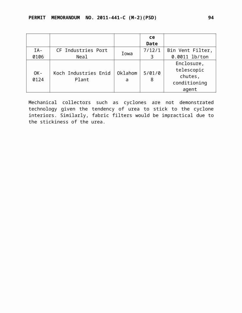
SPECIFIC CONDITIONS NO. 2011-441-C (M-2)(PSD) 16
EUG 20. Gasoline Tank
Unit ID Point EU Description Capacity Construction DateGasoline Gasoline Vehicle gasoline tank 1,128 gal Pre-2003
A. The gasoline storage tank shall be equipped and operated with a permanent submerged fill pipe. [OAC 252:100-37-15(b)]
B. The owner/operator shall comply with all applicable requirements of the NESHAP Subpart CCCCCC, for each affected facility including but not limited to:
[40 CFR 63.11110 through 63.11132]
1. Minimize gasoline spills;2. Clean up spills as expeditiously as practicable;3. Cover all open gasoline containers and all gasoline storage tank fill-pipes with a
gasketed seal when not in use;4. Minimize gasoline sent to open waste collection systems that collect and transport
gasoline to reclamation and recycling devices, such as oil/water separators.
EUG 21: No. 2 Urea Plant Synthesis Vent
Point ID
EmissionUnit
PM10 / PM2.5 SO2 NOx VOC CO
lb/hr TPY lb/hr TPY lb/hr TPY lb/
hr TPY lb/hr TPY
21-9163 No. 2 Urea Plant Vent 0.05 0.20 -- -- -- -- -- -- 3.08 12.83
A. Compliance Demonstration: Compliance with these limits is demonstrated by Urea production of 2,425 TPD (monthly average) or less.
B. Within 180 days following commencement of operations of the new urea granulator, the permittee shall conduct performance testing as follows and furnish a written report to Air Quality. [OAC 252:100-43]
C. The following USEPA methods shall be used for testing of emissions, unless otherwise approved by Air Quality:
Method 1: Sample and Velocity Traverses for Stationary Sources.Method 2: Determination of Stack Gas Velocity and Volumetric Flow Rate.Method 3: Gas Analysis for Carbon Dioxide, Excess Air, and Dry Molecular
Weight.Method 4: Moisture in Stack Gases.Method 5: PM Emissions from Stationary SourcesMethod 202: Condensable PM Emissions from Stationary Sources
D. A copy of the test plan shall be provided to AQD at least 30 days prior to each test date.
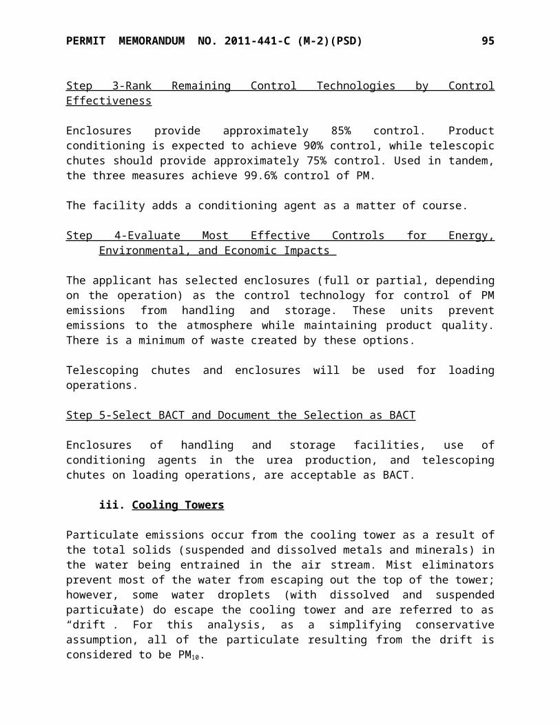
SPECIFIC CONDITIONS NO. 2011-441-C (M-2)(PSD) 17
E. Performance testing shall be conducted while the units are operating within 10% of the rates at which operating permit authorization will be sought.
F. At least 30 days prior to the testing, a notification of the test date and testing protocol shall be submitted to AQD. Deficiencies in the protocol shall be resolved prior to commencement of testing.
EUG 22: No. 2 Urea Plant Granulator
Point ID EmissionUnit
PM10 / PM2.5 SO2 NOx VOC COlb/hr TPY lb/hr TPY lb/hr TPY lb/hr TPY lb/hr TPY
22-9164No. 2 Urea
Plant Granulator
6.04 26.45 -- -- -- -- 2.39 8.44 -- --
A. All discharges from each urea granulation operation shall be processed by a high-effi-ciency spray tower wet scrubber or equivalent device for PM emissions control. PM emissions shall not exceed 0.1 lb per ton urea product. [OAC 252:100-8-34(b)(1)]
B. As part of the operating permit application, the permittee shall specify control device operating parameters which achieve the stated limitations. [OAC 252:100-43]
C. The permittee is subject to following requirements under 40 CFR 60, Subpart VVa for the urea plant, as applicable:
i. 60.486a: Recordkeeping requirementsii. 60.487a. Reporting requirements
D. Within 180 days following commencement of operations of the new urea granulator, the permittee shall conduct performance testing as follows and furnish a written report to Air Quality. [OAC 252:100-43]
E. The following USEPA methods shall be used for testing of emissions, unless otherwise approved by Air Quality:
Method 1: Sample and Velocity Traverses for Stationary Sources.Method 2: Determination of Stack Gas Velocity and Volumetric Flow Rate.Method 3: Gas Analysis for Carbon Dioxide, Excess Air, and Dry Molecular
Weight.Method 4: Moisture in Stack Gases.Method 5: PM Emissions from Stationary SourcesMethod 25A: VOC Emissions from Stationary SourcesMethod 202: Condensable PM Emissions from Stationary Sources
F. A copy of the test plan shall be provided to AQD at least 30 days prior to each test date.

SPECIFIC CONDITIONS NO. 2011-441-C (M-2)(PSD) 18
G. Performance testing shall be conducted while the units are operating within 10% of the rates at which operating permit authorization will be sought.
H. At least 30 days prior to the testing, a notification of the test date and testing protocol shall be submitted to AQD. Deficiencies in the protocol shall be resolved prior to commencement of testing.
EUG 23: No. 2 Urea Plant Boiler
Point ID EmissionUnit
PM10 / PM2.5 SO2 NOx VOC COlb/hr TPY lb/hr TPY lb/hr TPY lb/hr TPY lb/hr TPY
23-9165No. 2 Urea
Plant Boiler
3.35 14.69 0.26 1.16 20.25 88.70 2.43 10.63 16.65 72.93
A. The above fuel burning equipment shall be fueled by pipeline quality natural gas.
B. The boiler is subject to federal New Source Performance Standards, 40 CFR Part 60, Subpart Db, and shall comply with all applicable requirements, including, but not necessarily limited to those conditions shown following. (NOTE: Permit limitations are more stringent than Db limitations and will result in compliance with Subpart Db.)
[40 CFR 60.40b through 60.49b]
1. The boiler shall not discharge into the atmosphere any gases that contain nitrogen oxides (expressed as nitrogen dioxide) in excess of 0.20 lbs/MMBTU, 3-hour rolling average. [40 CFR 60.44b(a)(1)(ii)]
2. § 60.46b Performance test and compliance provisions; 3. § 60.48b Emission Monitoring, and4. § 60.49b Reporting and recordkeeping requirements.
C. Sulfur oxide emissions (measured as sulfur dioxide) from any new gas-fired fuel-burning equipment shall not exceed 0.2 lbs/MMBtu-heat input (86 ng/J), three hour average. [OAC 252:100-31-25(a)(1)]
D. Combustion CO2e emissions shall not exceed 117 lb CO2e / MMBTU heat input (30 day rolling average). [OAC 252:100-8-34(b)]
E. Within 180 days following commencement of operations of the boiler, performance testing shall be conducted and a written report of results submitted to AQD. The following USEPA methods shall be used for testing of emissions, unless otherwise approved by Air Quality: [OAC 252:100-43]
Method 1: Sample and Velocity Traverses for Stationary Sources.Method 2: Determination of Stack Gas Velocity and Volumetric Flow Rate.Method 3: Gas Analysis for Carbon Dioxide, Excess Air, and Dry Molecular Weight.Method 4: Moisture in Stack Gases.
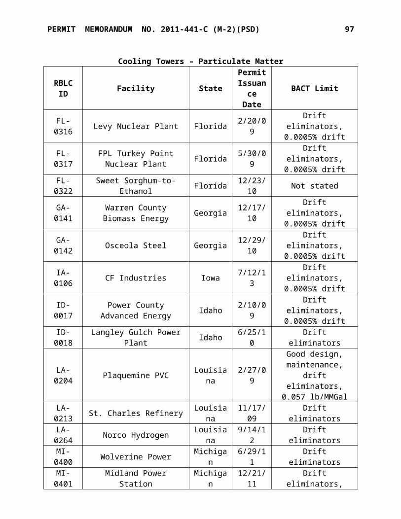
SPECIFIC CONDITIONS NO. 2011-441-C (M-2)(PSD) 19
Method 7E: NOx Emissions from Stationary SourcesMethod 10: Carbon Monoxide Emissions from Stationary SourcesMethod 25A: VOC Emissions from Stationary Sources
F. A copy of the test plan shall be provided to AQD at least 30 days prior to each test date.
G. Performance testing shall be conducted while the boiler is operating within 10% of the rates at which operating permit authorization will be sought.
H. At least 30 days prior to the testing, a notification of the test date and testing protocol shall be submitted to AQD. Deficiencies in the protocol shall be resolved prior to commencement of testing.
EUG 25: No. 2 Urea Plant Cooling Tower
Point ID
EmissionUnit
PM10 PM2.5 NOx VOC COlb/hr TPY lb/hr TPY lb/hr TPY lb/hr TPY lb/hr TPY
25-9167
No. 2 Urea Plant
Cooling Tower
0.20 0.86 0.01 0.01 -- -- -- -- -- --
A. Compliance Demonstrations: the following records shall be kept for the No. 2 Urea Plant Cooling Tower: [OAC 252:100-43]
i. Records of vendor certification of maximum circulation rateii. Records of design and construction showing 0.0005% or better drift.iii. Records of TDS content of cooling water, tested within 180 days of start-up.
EUG 26 No. 2 Urea Plant Fugitive PM
EU ID Point ID EU NameUR2MLD 26-9170 No. 2 Urea Materials Loading
UR2MSTG 26-9168 No. 2 Urea Materials StorageUR2MTRFR 26-9169 No. 2 Urea Materials Transfer
A. All conveyors between granulation, storage, and loading shall be equipped with wind shields. [OAC 252:100-8-6(a)]
B. Loading of product into trucks and railcars shall be conducted inside enclosures on at least two sides using telescoping chutes into the receiving vessels. [OAC 252:100-8-6(a)]
C. Storage of urea product shall be done in an enclosed building or other vessel shielded from winds. [OAC 252:100-8-6(a)]

SPECIFIC CONDITIONS NO. 2011-441-C (M-2)(PSD) 20
EUG 27: New Haul Roads
EU ID Point ID EU NameHAULRD HAULRD No. 2 Urea Plant Vehicle Traffic
A. Haul roads in the No. 2 Urea Plant loading area shall be paved. [OAC 252:100-29]
B. The roads shall be watered and swept daily as necessary to control fugitive dust, except when the following conditions occur: [OAC 252:100-29]
i. Sweeping and watering need not occur on any day that the haul road is not in use.
ii. Sweeping and watering need not occur when a rain gauge located at the facility indicates that at least 0.2 inches of precipitation (water equivalent) has occurred within the preceding 24-hour time period.
iii. Sweeping and watering will not be required on calendar days where the daily high temperature is below 35 degrees F.
iv. If the facility has applied salt or sand for worker or driver safety the facility is not required to sweep or wash until the road has returned to driving conditions that no longer require the use of salt or sand.
C. The permittee shall maintain daily records of road watering and sweeping activities.
2. The permittee is authorized to operate the facility continuously (24 hours per day, every day of the year). [OAC 252:100-8-6(a)]
3. The facility is subject to 40 CFR Part 61, Subpart FF, and shall comply with the following standards: [40 CFR Part 61.340]
A. 61.342: Standards, GeneralB. 61.355: Test Methods, Procedures, and Compliance ProvisionsC. 61.356: Recordkeeping RequirementsD. 61.357: Reporting Requirements
4. Upon the compliance date of NESHAPS Subpart VVVVVV, the owner/operator shall comply with all applicable requirements of the NESHAP: Chemical Manufacturing Process Sources, Subpart VVVVVV, for each affected facility including but not limited to:
[40 CFR 63.11494 through 63.11501]
A. § 63.11494 What are the applicability requirements and compliance dates?B. § 63.11495 What are the management practices and other requirements?C. § 63.11496 What are the standards and compliance requirements for process vents?D. § 63.11497 What are the standards and compliance requirements for storage tanks?E. § 63.11498 What are the standards and compliance requirements for wastewater
systems?F. § 63.11499 What are the standards and compliance requirements for heat exchange
systems?
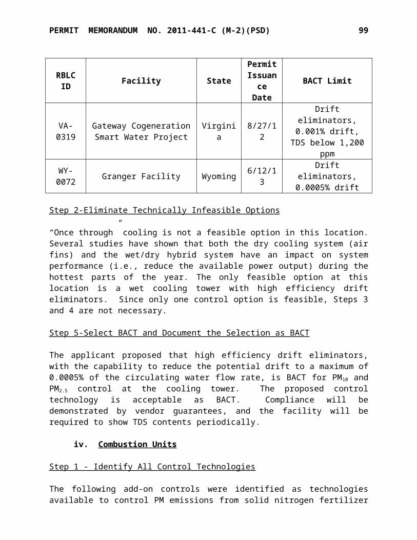
SPECIFIC CONDITIONS NO. 2011-441-C (M-2)(PSD) 21
G. § 63.11500 What compliance options do I have if part of my plant is subject to both this standard and another Federal standard?
H. § 63.11501 What are the notification, recordkeeping, and reporting requirements?I. § 63.11502 What definitions apply to this subpart?J. § 63.11503 Who implements and enforces this subpart?
5. The following records shall be maintained on location for inspection by ODEQ regulatory personnel. The required records shall be retained either in printed hard-copy or electronically for a period of at least five (5) years following the dates of recording. [OAC 252:100-43]
A. Plant-wide 12-month rolling total methanol emissions calculations in EUG 1 (monthly).
B. Records of conditioning agent usage from each granular urea plant EUG 6 and EUG 22 (monthly).
C. Records of conditioning agent methanol content from vendor, with actual annual methanol content calculated on a 12-month rolling average basis for each granular urea plant for EUG 6 and EUG 22.
D. Granular urea production rates for each granular urea plant for EUG 6 and EUG 22 (monthly).
E. Granular urea truck and railcar loading rates for the two urea materials loading areas, EUG 14 and 26 (monthly).
F. Monitoring of NOx concentrations in exhausts from the EUG 11 Nitric Acid plant (continuous when operated).
G. Nitric acid production rates, expressed as 100% nitric acid for EUG 11 (monthly).H. UAN production rates, expressed as 32% nitrogen for EUG 12 (monthly).I. Estimated quantities of ammonia, process off-gas sent to the EUG 13 flare (monthly).J. Venting episodes from EUG 15, including methods, assumptions, and duration of
each event as used in calculating emission rates during venting episodes, and CO emission rates (12-month rolling total).
K. Visible observations records where required for EUG 6 and EUG 12 (monthly).L. Reference Method 9 results as set forth in Item A for EUG 6 and EUG 12 (as needed,
if applicable).M. Duration (hours) of venting as needed to calculate CO emissions from EUG 10
(monthly), and CO emission rates (monthly and 12-month rolling totals)`.N. Hours of operation of the ammonia unit startup boiler in EUG 3 (monthly and 12-
month rolling totals).O. Records as required by 40 CFR Part 61, Subpart FF for Specific Condition 3.P. Records as required by 40 CFR Part 60, Subpart VVa for No. 1 and No. 2 Urea Plants
(per EUG 6 and EUG 22).Q. Pressure differentials of each urea granulator wet scrubber (daily when operated), No
1 Urea granulators (EUG 6).R. For the fuel(s) burned, the appropriate document(s) as described in Specific Condition
No. 1, EUGs 1, 2, 3, 4, 13, and 23.S. Records of fuels used in EUG-1, EUG-2, and EUG-11.T. Records as required by NSPS Subpart JJJJ and NESHAP Subpart ZZZZ for the
emergency generators in EUG-18 and 19. U. Records of average hourly heat input for each reformer, monthly, as required by
EUG-2.
SPECIFIC CONDITIONS NO. 2011-441-C (M-2)(PSD) 22
V. Records as required by 40 CFR Part 63, Subpart CCCCCC for EUG 20. W. Numbers and durations of each start-up and shutdown event for EUG-11, the Nitric
Acid Plant.X. Records as required by 40 CFR Part 63, Subpart VVVVVV for Specific Condition 4. Y. Records as required by NSPS Subpart Db for EUG 23, the No. 2 Urea Boiler.Z. Records of TDS testing in the No. 2 Urea Cooling Tower (EUG 25) and No. 2
Ammonia Cooling Tower (EUG 9).AA. Ammonia production records for EUG 1 (monthly)BB. Process CO2 calculations using 40 CFR 98, Subpart G for EUG 1 (monthly)CC. CO2 sales and usage records for EUG 1 (monthly)DD. Records of WESP operating parameters developed for No. 2 Urea Granulator
WESP and pressure differentials of the urea granulator wet scrubber for EUG 22 (daily when operated)
EE.Records of road watering and sweeping activities for EUG 27 (daily)
6. The following records shall be maintained on-site to verify Insignificant Activities. No recordkeeping is required for those operations that qualify as Trivial Activities.
[OAC 252:100-8-6 (a)(3)(B)]
A. Hours of operation and the production rates of the portable fertilizer mixing unit and engine.
B. Fuel dispensing to facility owned vehicles: annual throughput of diesel.C. Lime silos: inspection and maintenance of the dust collector.D. Diesel storage tanks: records of tank capacities and tank contents.E. UAN storage tanks: records of tank capacities and tank contents.F. For other activities that have the potential emissions less than 5 TPY (actual): type of
activity and the amount of emissions from the activity.
7. No later than 30 days after each anniversary of the original Title V operating permit (December 18, 2006), the permittee shall submit to Air Quality Division of DEQ, with a copy to the US EPA, Region 6, a certification of compliance with the terms and conditions of the Title V operating permit. [OAC 252:100-8-6 (c)(5)(A) & (D)]
8. Deviations from the 40 CFR Part 68 regulations that arise from review of process safety man-agement procedures and programs, including deviations identified in the process safety manage-ment audits, will not be considered deviations of this permit.
9. At least once every two years, the permittee shall conduct performance testing as follows and furnish a written report to Air Quality. [OAC 252:100-43]
A. The following USEPA methods shall be used for testing of emissions, unless otherwise approved by Air Quality:
Method 1: Sample and Velocity Traverses for Stationary Sources.Method 2: Determination of Stack Gas Velocity and Volumetric Flow Rate.Method 3: Gas Analysis for Carbon Dioxide, Excess Air, and Dry Molecular
Weight.Method 4: Moisture in Stack Gases.

SPECIFIC CONDITIONS NO. 2011-441-C (M-2)(PSD) 23
Method 7E: NOx Emissions from Stationary SourcesMethod 10: Carbon Monoxide Emissions from Stationary Sources
B. A copy of the test plan shall be provided to AQD at least 30 days prior to each test date.
C. Performance testing shall be conducted while the units are operating within 10% of the rates at which operating permit authorization will be sought.
D. At least 30 days prior to the testing, a notification of the test date and testing protocol shall be submitted to AQD. Deficiencies in the protocol shall be resolved prior to commencement of testing.
E. The following pollutants shall be tested for on each of the listed units:
Unit ID Description Pollutants Tested101B1 Ammonia Plant No. 1 Reformer NOx, CO101B2 Ammonia Plant No. 2 Reformer NOx, CO
F. Alternatively to the stack testing, if Continuous Emissions Monitoring Systems (CEMS) is installed for NOx or CO and certified using the methods and procedures of 40 CFR 60, Appendices B and F, the above stack testing will not be required for that pollutant where a related CEMS unit has been installed.
10. The permittee shall apply for a modified operating permit within 180 days of commencement of operations of any new or physically modified unit. [OAC 252:100-8-6]
11. The Permit Shield (Standard Conditions, Section VI) is extended to the following require-ments that have been determined to be inapplicable to this facility or the listed emission unit groups. [OAC 252:100-8-6(d)(2)]
A. Facility WideCitation Description Reason for Non-ApplicabilityOAC 252:100-7 Minor Sources not in source category
OAC 252:100-11 Alternative Reduction Plans and Authorizations not in source category
OAC 252:100-15 Mobile Sources not in source categoryOAC 252:100-17 Incinerators not type of emission unitOAC 252:100-23 Cotton Gins not type of emission unitOAC 252:100-24 Grain Elevators not in source category
OAC 252:100-31, Part 2 Sulfur Compounds, Ambient Concentrations not in source category
OAC 252:100-35 Carbon Monoxide not in source categoryOAC 252:100-39 Nonattainment Areas not in area categoryOAC 252:100-47 Landfills not in source category40 CFR 60 Subpart D Steam Generators below the specified size40 CFR 60 Subpart Dc Steam Generating Units prior to the effective date40 CFR 60 Subpart G Nitric Acid Plants prior to the effective date
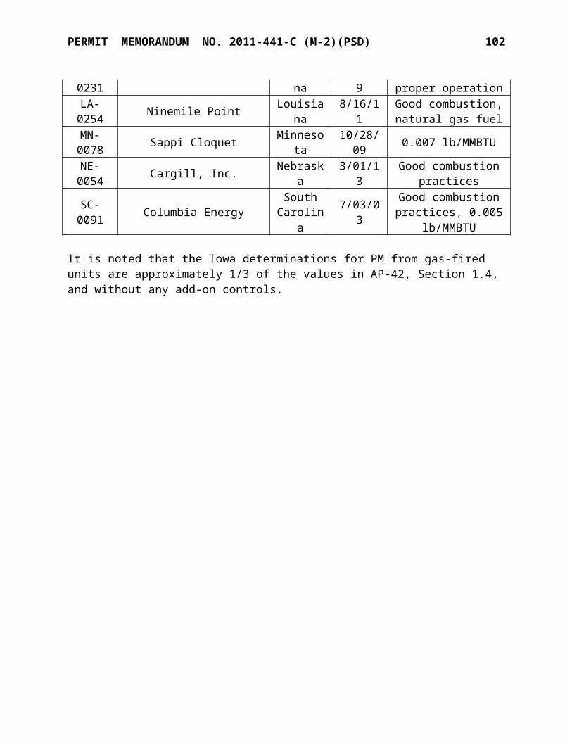
SPECIFIC CONDITIONS NO. 2011-441-C (M-2)(PSD) 24
40 CFR 60 Subpart Ga Nitric Acid Plants prior to the effective date
40 CFR 60 Subpart Kb Volatile Organic Liquid Storage vapor pressure of stored material below applicability threshold
40 CFR 61, all subparts except M and FF NESHAP not in source category, not a major
source of HAPs40 CFR 63, all subparts related to Title III major sources NESHAP not a major source of HAPs
40 CFR 63, Subpart JJJJJJ Area Source Boiler GACT not applicable
40 CFR 64 Compliance Assurance Monitoring not applicable
B. By Emission Unit Grouping
EUG Citation Description Reason for Non-Applicability
EUG 2 40 CFR 60, Subpart D Steam Generating Units > 250 MMBTUH below the specified size
EUG 2,3 40 CFR 60, Subpart Db Steam Generating Units 100-250 MMBTUH prior to the effective date
EUG 3 40 CFR 60, Subpart Dc Steam Generating Units 10-100 MMBTUH prior to the effective date
EUG 11 40 CFR 60, Subpart G and Ga Nitric Acid Plants prior to the effective date
EUG 13 40 CFR 60, Subpart A, 60.18 Flare Not in source category
EUG 5, 17 40 CFR 60, Subpart Kb Storage Vesselsvapor pressure of stored material below applicability threshold
EUG 2 OAC 252:100-31-25 (c) Sulfur Compounds, Fuel and Emissions Monitoring not in source category
EUG 4 and 23 OAC 252:100-33 Control of Emission of Nitrogen
Oxides below the specified size
EUG 5 and 17 OAC 252:100-37 Control of Emission of VOC below the specified vapor
pressureEUG 6, 7, 9, 12, 13, 14, 14A, 16, 17, 21, 22, 25, 26, 27
OAC 252:100-19-4 PM Emissions from Fuel Burning Units not in source category
EUG 5-17, 20-22, 24-25
OAC 252:100-31 Control of Emission of Sulfur Compounds not in source category
EUG 5-17, 20-22, 24-27
OAC 252:100-33 Control of Emissions of Nitrogen Oxide not in source category
EUG 6-17, 20-22, 25-27
OAC 252:100-37 Control of Emission of VOC not in source category
EUG 4, 7, 11, 12, 13,
OAC 252:100-8, Part 7 Prevention of Significant Deterioration
No changes have been made to trigger this

SPECIFIC CONDITIONS NO. 2011-441-C (M-2)(PSD) 25
15, 17 - 20 requirements for these sources

PART 70 PERMITAIR QUALITY DIVISIONSTATE OF OKLAHOMA
DEPARTMENT OF ENVIRONMENTAL QUALITY707 N. ROBINSON, SUITE 4100
P.O. BOX 1677OKLAHOMA CITY, OKLAHOMA 73101-1677
Permit No. 2011-441-C (M-2)(PSD)
Koch Nitrogen Company,
having complied with the requirements of the law, is hereby granted permission to
construct modifications to the Enid Nitrogen Plant located at 1619 South 78 th , Enid,
Garfield County, Oklahoma, subject to standard conditions dated July 21, 2009, and
specific conditions, both attached.
In the absence of commencement of construction, this permit shall expire 18 months from the date below, except as authorized under Section VIII of the Standard Conditions.
__________________________________
Division Director Date

Koch Nitrogen CompanyAttn: Mr. Cody Greenfield1619 S. 78th StreetEnid, OK 73701
Re: Permit Application No. 2011-441-C (M-2)(PSD)Enid Nitrogen PlantEnid, Garfield County, Oklahoma
Dear Mr. Greenfield:
Enclosed is the permit authorizing construction of the referenced facility. Please note that this permit is issued subject to standard and specific conditions, which are attached. These conditions must be carefully followed since they define the limits of the permit and will be confirmed by periodic inspections.
Also note that you are required to annually submit an emissions inventory for this facility. An emissions inventory must be completed on approved AQD forms and submitted (hardcopy or electronically) by April 1st of every year. Any questions concerning the form or submittal process should be referred to the Emissions Inventory Staff at (405) 702-4100.
Thank you for your cooperation in this matter. If we may be of further service, please contact our office at (405)702-4100.
Sincerely,
David S. Schutz, P.E.AIR QUALITY DIVISION
Enclosure

MAJOR SOURCE AIR QUALITY PERMITSTANDARD CONDITIONS
(July 21, 2009)
SECTION I. DUTY TO COMPLY
A. This is a permit to operate / construct this specific facility in accordance with the federal Clean Air Act (42 U.S.C. 7401, et al.) and under the authority of the Oklahoma Clean Air Act and the rules promulgated there under. [Oklahoma Clean Air Act, 27A O.S. § 2-5-112]
B. The issuing Authority for the permit is the Air Quality Division (AQD) of the Oklahoma Department of Environmental Quality (DEQ). The permit does not relieve the holder of the obligation to comply with other applicable federal, state, or local statutes, regulations, rules, or ordinances. [Oklahoma Clean Air Act, 27A O.S. § 2-5-112]
C. The permittee shall comply with all conditions of this permit. Any permit noncompliance shall constitute a violation of the Oklahoma Clean Air Act and shall be grounds for enforcement action, permit termination, revocation and reissuance, or modification, or for denial of a permit renewal application. All terms and conditions are enforceable by the DEQ, by the Environmental Protection Agency (EPA), and by citizens under section 304 of the Federal Clean Air Act (excluding state-only requirements). This permit is valid for operations only at the specific location listed.
[40 C.F.R. §70.6(b), OAC 252:100-8-1.3 and OAC 252:100-8-6(a)(7)(A) and (b)(1)]
D. It shall not be a defense for a permittee in an enforcement action that it would have been necessary to halt or reduce the permitted activity in order to maintain compliance with the conditions of the permit. However, nothing in this paragraph shall be construed as precluding consideration of a need to halt or reduce activity as a mitigating factor in assessing penalties for noncompliance if the health, safety, or environmental impacts of halting or reducing operations would be more serious than the impacts of continuing operations. [OAC 252:100-8-6(a)(7)(B)]
SECTION II. REPORTING OF DEVIATIONS FROM PERMIT TERMS
A. Any exceedance resulting from an emergency and/or posing an imminent and substantial danger to public health, safety, or the environment shall be reported in accordance with Section XIV (Emergencies). [OAC 252:100-8-6(a)(3)(C)(iii)(I) & (II)]
B. Deviations that result in emissions exceeding those allowed in this permit shall be reported consistent with the requirements of OAC 252:100-9, Excess Emission Reporting Requirements.
[OAC 252:100-8-6(a)(3)(C)(iv)]
C. Every written report submitted under this section shall be certified as required by Section III (Monitoring, Testing, Recordkeeping & Reporting), Paragraph F.
[OAC 252:100-8-6(a)(3)(C)(iv)]

MAJOR SOURCE STANDARD CONDITIONS July 21, 2009 2
SECTION III. MONITORING, TESTING, RECORDKEEPING & REPORTING
A. The permittee shall keep records as specified in this permit. These records, including monitoring data and necessary support information, shall be retained on-site or at a nearby field office for a period of at least five years from the date of the monitoring sample, measurement, report, or application, and shall be made available for inspection by regulatory personnel upon request. Support information includes all original strip-chart recordings for continuous monitoring instrumentation, and copies of all reports required by this permit. Where appropriate, the permit may specify that records may be maintained in computerized form.
[OAC 252:100-8-6 (a)(3)(B)(ii), OAC 252:100-8-6(c)(1), and OAC 252:100-8-6(c)(2)(B)]
B. Records of required monitoring shall include:(1) the date, place and time of sampling or measurement;(2) the date or dates analyses were performed;(3) the company or entity which performed the analyses;(4) the analytical techniques or methods used;(5) the results of such analyses; and(6) the operating conditions existing at the time of sampling or measurement.
[OAC 252:100-8-6(a)(3)(B)(i)]
C. No later than 30 days after each six (6) month period, after the date of the issuance of the original Part 70 operating permit or alternative date as specifically identified in a subsequent Part 70 operating permit, the permittee shall submit to AQD a report of the results of any required monitoring. All instances of deviations from permit requirements since the previous report shall be clearly identified in the report. Submission of these periodic reports will satisfy any reporting requirement of Paragraph E below that is duplicative of the periodic reports, if so noted on the submitted report. [OAC 252:100-8-6(a)(3)(C)(i) and (ii)]
D. If any testing shows emissions in excess of limitations specified in this permit, the owner or operator shall comply with the provisions of Section II (Reporting Of Deviations From Permit Terms) of these standard conditions. [OAC 252:100-8-6(a)(3)(C)(iii)]
E. In addition to any monitoring, recordkeeping or reporting requirement specified in this permit, monitoring and reporting may be required under the provisions of OAC 252:100-43, Testing, Monitoring, and Recordkeeping, or as required by any provision of the Federal Clean Air Act or Oklahoma Clean Air Act. [OAC 252:100-43]
F. Any Annual Certification of Compliance, Semi Annual Monitoring and Deviation Report, Excess Emission Report, and Annual Emission Inventory submitted in accordance with this permit shall be certified by a responsible official. This certification shall be signed by a responsible official, and shall contain the following language: “I certify, based on information and belief formed after reasonable inquiry, the statements and information in the document are true, accurate, and complete.”
[OAC 252:100-8-5(f), OAC 252:100-8-6(a)(3)(C)(iv), OAC 252:100-8-6(c)(1), OAC 252:100-9-7(e), and OAC 252:100-5-2.1(f)]
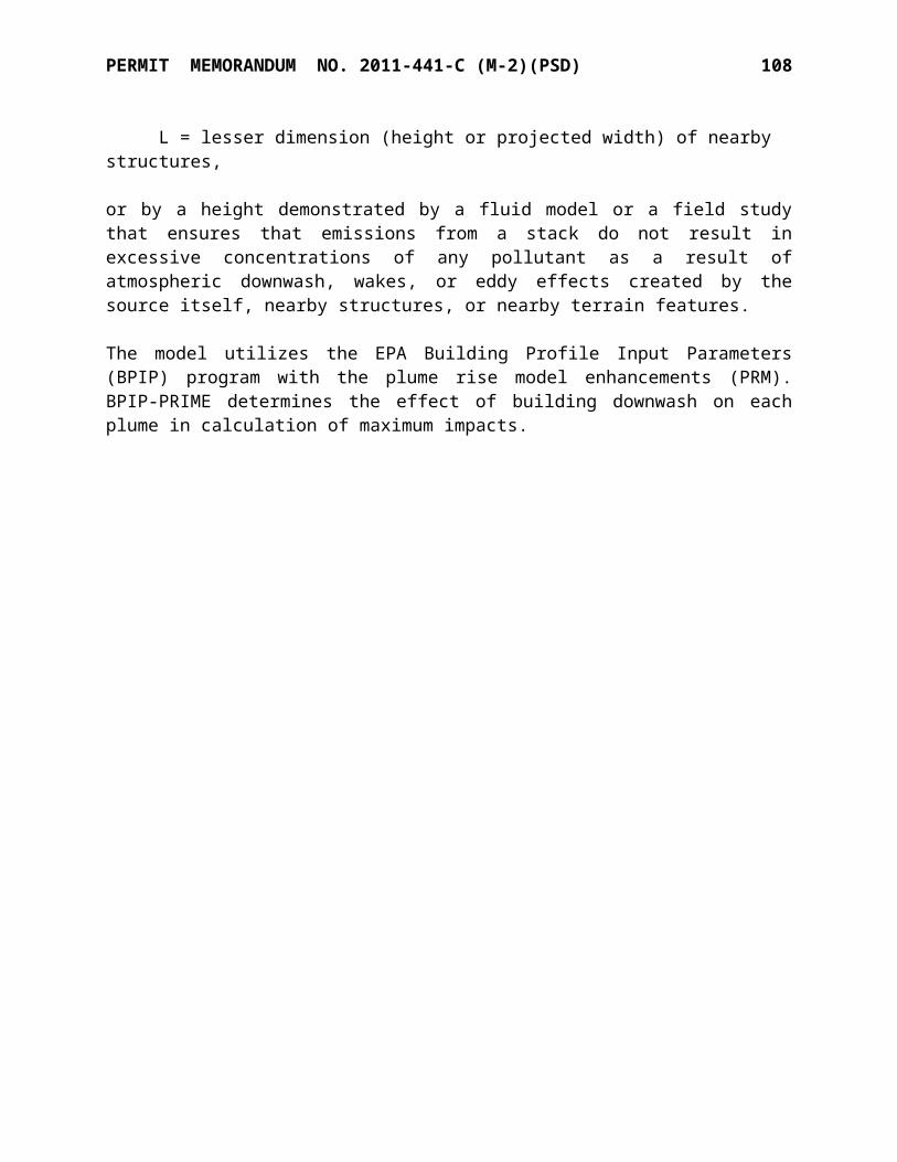
MAJOR SOURCE STANDARD CONDITIONS July 21, 2009 3
G. Any owner or operator subject to the provisions of New Source Performance Standards (“NSPS”) under 40 CFR Part 60 or National Emission Standards for Hazardous Air Pollutants (“NESHAPs”) under 40 CFR Parts 61 and 63 shall maintain a file of all measurements and other information required by the applicable general provisions and subpart(s). These records shall be maintained in a permanent file suitable for inspection, shall be retained for a period of at least five years as required by Paragraph A of this Section, and shall include records of the occurrence and duration of any start-up, shutdown, or malfunction in the operation of an affected facility, any malfunction of the air pollution control equipment; and any periods during which a continuous monitoring system or monitoring device is inoperative.
[40 C.F.R. §§60.7 and 63.10, 40 CFR Parts 61, Subpart A, and OAC 252:100, Appendix Q]
H. The permittee of a facility that is operating subject to a schedule of compliance shall submit to the DEQ a progress report at least semi-annually. The progress reports shall contain dates for achieving the activities, milestones or compliance required in the schedule of compliance and the dates when such activities, milestones or compliance was achieved. The progress reports shall also contain an explanation of why any dates in the schedule of compliance were not or will not be met, and any preventive or corrective measures adopted. [OAC 252:100-8-6(c)(4)]
I. All testing must be conducted under the direction of qualified personnel by methods approved by the Division Director. All tests shall be made and the results calculated in accordance with standard test procedures. The use of alternative test procedures must be approved by EPA. When a portable analyzer is used to measure emissions it shall be setup, calibrated, and operated in accordance with the manufacturer’s instructions and in accordance with a protocol meeting the requirements of the “AQD Portable Analyzer Guidance” document or an equivalent method approved by Air Quality.
[OAC 252:100-8-6(a)(3)(A)(iv), and OAC 252:100-43]
J. The reporting of total particulate matter emissions as required in Part 7 of OAC 252:100-8 (Permits for Part 70 Sources), OAC 252:100-19 (Control of Emission of Particulate Matter), and OAC 252:100-5 (Emission Inventory), shall be conducted in accordance with applicable testing or calculation procedures, modified to include back-half condensables, for the concentration of particulate matter less than 10 microns in diameter (PM10). NSPS may allow reporting of only particulate matter emissions caught in the filter (obtained using Reference Method 5).
K. The permittee shall submit to the AQD a copy of all reports submitted to the EPA as required by 40 C.F.R. Part 60, 61, and 63, for all equipment constructed or operated under this permit subject to such standards. [OAC 252:100-8-6(c)(1) and OAC 252:100, Appendix Q]
SECTION IV. COMPLIANCE CERTIFICATIONS
A. No later than 30 days after each anniversary date of the issuance of the original Part 70 operating permit or alternative date as specifically identified in a subsequent Part 70 operating permit, the permittee shall submit to the AQD, with a copy to the US EPA, Region 6, a certification of compliance with the terms and conditions of this permit and of any other applicable requirements which have become effective since the issuance of this permit.
[OAC 252:100-8-6(c)(5)(A), and (D)]
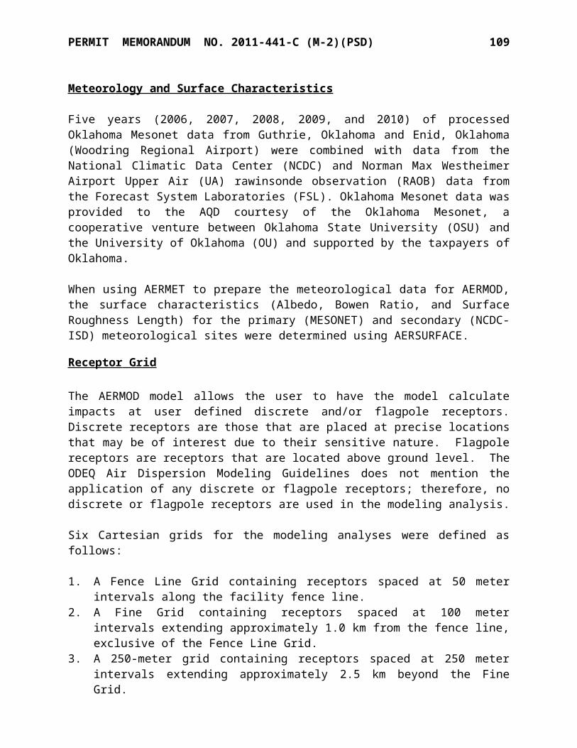
MAJOR SOURCE STANDARD CONDITIONS July 21, 2009 4
B. The compliance certification shall describe the operating permit term or condition that is the basis of the certification; the current compliance status; whether compliance was continuous or intermittent; the methods used for determining compliance, currently and over the reporting period. The compliance certification shall also include such other facts as the permitting authority may require to determine the compliance status of the source.
[OAC 252:100-8-6(c)(5)(C)(i)-(v)]
C. The compliance certification shall contain a certification by a responsible official as to the results of the required monitoring. This certification shall be signed by a responsible official, and shall contain the following language: “I certify, based on information and belief formed after reasonable inquiry, the statements and information in the document are true, accurate, and complete.” [OAC 252:100-8-5(f) and OAC 252:100-8-6(c)(1)]
D. Any facility reporting noncompliance shall submit a schedule of compliance for emissions units or stationary sources that are not in compliance with all applicable requirements. This schedule shall include a schedule of remedial measures, including an enforceable sequence of actions with milestones, leading to compliance with any applicable requirements for which the emissions unit or stationary source is in noncompliance. This compliance schedule shall resemble and be at least as stringent as that contained in any judicial consent decree or administrative order to which the emissions unit or stationary source is subject. Any such schedule of compliance shall be supplemental to, and shall not sanction noncompliance with, the applicable requirements on which it is based, except that a compliance plan shall not be required for any noncompliance condition which is corrected within 24 hours of discovery.
[OAC 252:100-8-5(e)(8)(B) and OAC 252:100-8-6(c)(3)]
SECTION V. REQUIREMENTS THAT BECOME APPLICABLE DURING THE PERMIT TERM
The permittee shall comply with any additional requirements that become effective during the permit term and that are applicable to the facility. Compliance with all new requirements shall be certified in the next annual certification. [OAC 252:100-8-6(c)(6)]
SECTION VI. PERMIT SHIELD
A. Compliance with the terms and conditions of this permit (including terms and conditions established for alternate operating scenarios, emissions trading, and emissions averaging, but excluding terms and conditions for which the permit shield is expressly prohibited under OAC 252:100-8) shall be deemed compliance with the applicable requirements identified and included in this permit. [OAC 252:100-8-6(d)(1)]
B. Those requirements that are applicable are listed in the Standard Conditions and the Specific Conditions of this permit. Those requirements that the applicant requested be determined as not applicable are summarized in the Specific Conditions of this permit. [OAC 252:100-8-6(d)(2)]
MAJOR SOURCE STANDARD CONDITIONS July 21, 2009 5
SECTION VII. ANNUAL EMISSIONS INVENTORY & FEE PAYMENT
The permittee shall file with the AQD an annual emission inventory and shall pay annual fees based on emissions inventories. The methods used to calculate emissions for inventory purposes shall be based on the best available information accepted by AQD.
[OAC 252:100-5-2.1, OAC 252:100-5-2.2, and OAC 252:100-8-6(a)(8)]
SECTION VIII. TERM OF PERMIT
A. Unless specified otherwise, the term of an operating permit shall be five years from the date of issuance. [OAC 252:100-8-6(a)(2)(A)]
B. A source’s right to operate shall terminate upon the expiration of its permit unless a timely and complete renewal application has been submitted at least 180 days before the date of expiration. [OAC 252:100-8-7.1(d)(1)]
C. A duly issued construction permit or authorization to construct or modify will terminate and become null and void (unless extended as provided in OAC 252:100-8-1.4(b)) if the construction is not commenced within 18 months after the date the permit or authorization was issued, or if work is suspended for more than 18 months after it is commenced. [OAC 252:100-8-1.4(a)]
D. The recipient of a construction permit shall apply for a permit to operate (or modified operating permit) within 180 days following the first day of operation. [OAC 252:100-8-4(b)(5)]
SECTION IX. SEVERABILITY
The provisions of this permit are severable and if any provision of this permit, or the application of any provision of this permit to any circumstance, is held invalid, the application of such provision to other circumstances, and the remainder of this permit, shall not be affected thereby.
[OAC 252:100-8-6 (a)(6)]
SECTION X. PROPERTY RIGHTS
A. This permit does not convey any property rights of any sort, or any exclusive privilege.[OAC 252:100-8-6(a)(7)(D)]
B. This permit shall not be considered in any manner affecting the title of the premises upon which the equipment is located and does not release the permittee from any liability for damage to persons or property caused by or resulting from the maintenance or operation of the equipment for which the permit is issued. [OAC 252:100-8-6(c)(6)]

MAJOR SOURCE STANDARD CONDITIONS July 21, 2009 6
SECTION XI. DUTY TO PROVIDE INFORMATION
A. The permittee shall furnish to the DEQ, upon receipt of a written request and within sixty (60) days of the request unless the DEQ specifies another time period, any information that the DEQ may request to determine whether cause exists for modifying, reopening, revoking, reissuing, terminating the permit or to determine compliance with the permit. Upon request, the permittee shall also furnish to the DEQ copies of records required to be kept by the permit.
[OAC 252:100-8-6(a)(7)(E)]
B. The permittee may make a claim of confidentiality for any information or records submitted pursuant to 27A O.S. § 2-5-105(18). Confidential information shall be clearly labeled as such and shall be separable from the main body of the document such as in an attachment.
[OAC 252:100-8-6(a)(7)(E)]
C. Notification to the AQD of the sale or transfer of ownership of this facility is required and shall be made in writing within thirty (30) days after such sale or transfer.
[Oklahoma Clean Air Act, 27A O.S. § 2-5-112(G)]
SECTION XII. REOPENING, MODIFICATION & REVOCATION
A. The permit may be modified, revoked, reopened and reissued, or terminated for cause. Except as provided for minor permit modifications, the filing of a request by the permittee for a permit modification, revocation and reissuance, termination, notification of planned changes, or anticipated noncompliance does not stay any permit condition.
[OAC 252:100-8-6(a)(7)(C) and OAC 252:100-8-7.2(b)]
B. The DEQ will reopen and revise or revoke this permit prior to the expiration date in the following circumstances: [OAC 252:100-8-7.3 and OAC 252:100-8-7.4(a)(2)]
(1) Additional requirements under the Clean Air Act become applicable to a major source category three or more years prior to the expiration date of this permit. No such reopening is required if the effective date of the requirement is later than the expiration date of this permit.
(2) The DEQ or the EPA determines that this permit contains a material mistake or that the permit must be revised or revoked to assure compliance with the applicable requirements.
(3) The DEQ or the EPA determines that inaccurate information was used in establishing the emission standards, limitations, or other conditions of this permit. The DEQ may revoke and not reissue this permit if it determines that the permittee has submitted false or misleading information to the DEQ.
(4) DEQ determines that the permit should be amended under the discretionary reopening provisions of OAC 252:100-8-7.3(b).
C. The permit may be reopened for cause by EPA, pursuant to the provisions of OAC 100-8-7.3(d). [OAC 100-8-7.3(d)]
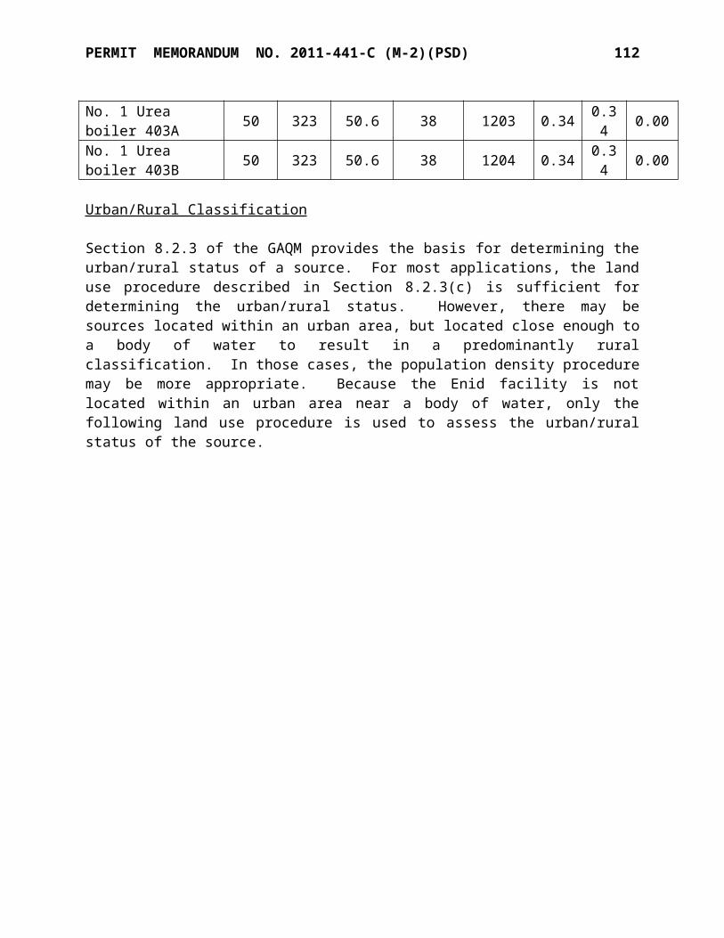
MAJOR SOURCE STANDARD CONDITIONS July 21, 2009 7
D. The permittee shall notify AQD before making changes other than those described in Section XVIII (Operational Flexibility), those qualifying for administrative permit amendments, or those defined as an Insignificant Activity (Section XVI) or Trivial Activity (Section XVII). The notification should include any changes which may alter the status of a “grandfathered source,” as defined under AQD rules. Such changes may require a permit modification.
[OAC 252:100-8-7.2(b) and OAC 252:100-5-1.1]
E. Activities that will result in air emissions that exceed the trivial/insignificant levels and that are not specifically approved by this permit are prohibited. [OAC 252:100-8-6(c)(6)]
SECTION XIII. INSPECTION & ENTRY
A. Upon presentation of credentials and other documents as may be required by law, the permittee shall allow authorized regulatory officials to perform the following (subject to the permittee's right to seek confidential treatment pursuant to 27A O.S. Supp. 1998, § 2-5-105(18) for confidential information submitted to or obtained by the DEQ under this section):
(1) enter upon the permittee's premises during reasonable/normal working hours where a source is located or emissions-related activity is conducted, or where records must be kept under the conditions of the permit;
(2) have access to and copy, at reasonable times, any records that must be kept under the conditions of the permit;
(3) inspect, at reasonable times and using reasonable safety practices, any facilities, equipment (including monitoring and air pollution control equipment), practices, or operations regulated or required under the permit; and
(4) as authorized by the Oklahoma Clean Air Act, sample or monitor at reasonable times substances or parameters for the purpose of assuring compliance with the permit.
[OAC 252:100-8-6(c)(2)]
SECTION XIV. EMERGENCIES
A. Any exceedance resulting from an emergency shall be reported to AQD promptly but no later than 4:30 p.m. on the next working day after the permittee first becomes aware of the exceedance. This notice shall contain a description of the emergency, the probable cause of the exceedance, any steps taken to mitigate emissions, and corrective actions taken.
[OAC 252:100-8-6 (a)(3)(C)(iii)(I) and (IV)]
B. Any exceedance that poses an imminent and substantial danger to public health, safety, or the environment shall be reported to AQD as soon as is practicable; but under no circumstance shall notification be more than 24 hours after the exceedance. [OAC 252:100-8-6(a)(3)(C)(iii)(II)]
C. An "emergency" means any situation arising from sudden and reasonably unforeseeable events beyond the control of the source, including acts of God, which situation requires immediate corrective action to restore normal operation, and that causes the source to exceed a technology-based emission limitation under this permit, due to unavoidable increases in emissions attributable to the emergency. An emergency shall not include noncompliance to the extent caused by improperly designed equipment, lack of preventive maintenance, careless or improper operation, or operator error. [OAC 252:100-8-2]

MAJOR SOURCE STANDARD CONDITIONS July 21, 2009 8
D. The affirmative defense of emergency shall be demonstrated through properly signed, contemporaneous operating logs or other relevant evidence that: [OAC 252:100-8-6 (e)(2)]
(1) an emergency occurred and the permittee can identify the cause or causes of the emergency;
(2) the permitted facility was at the time being properly operated;(3) during the period of the emergency the permittee took all reasonable steps to minimize
levels of emissions that exceeded the emission standards or other requirements in this permit.
E. In any enforcement proceeding, the permittee seeking to establish the occurrence of an emergency shall have the burden of proof. [OAC 252:100-8-6(e)(3)]
F. Every written report or document submitted under this section shall be certified as required by Section III (Monitoring, Testing, Recordkeeping & Reporting), Paragraph F.
[OAC 252:100-8-6(a)(3)(C)(iv)]
SECTION XV. RISK MANAGEMENT PLAN
The permittee, if subject to the provision of Section 112(r) of the Clean Air Act, shall develop and register with the appropriate agency a risk management plan by June 20, 1999, or the applicable effective date. [OAC 252:100-8-6(a)(4)]
SECTION XVI. INSIGNIFICANT ACTIVITIES
Except as otherwise prohibited or limited by this permit, the permittee is hereby authorized to operate individual emissions units that are either on the list in Appendix I to OAC Title 252, Chapter 100, or whose actual calendar year emissions do not exceed any of the limits below. Any activity to which a State or Federal applicable requirement applies is not insignificant even if it meets the criteria below or is included on the insignificant activities list.
(1) 5 tons per year of any one criteria pollutant.(2) 2 tons per year for any one hazardous air pollutant (HAP) or 5 tons per year for an
aggregate of two or more HAP's, or 20 percent of any threshold less than 10 tons per year for single HAP that the EPA may establish by rule.
[OAC 252:100-8-2 and OAC 252:100, Appendix I]
SECTION XVII. TRIVIAL ACTIVITIES
Except as otherwise prohibited or limited by this permit, the permittee is hereby authorized to operate any individual or combination of air emissions units that are considered inconsequential and are on the list in Appendix J. Any activity to which a State or Federal applicable requirement applies is not trivial even if included on the trivial activities list.
[OAC 252:100-8-2 and OAC 252:100, Appendix J]
MAJOR SOURCE STANDARD CONDITIONS July 21, 2009 9
SECTION XVIII. OPERATIONAL FLEXIBILITY
A. A facility may implement any operating scenario allowed for in its Part 70 permit without the need for any permit revision or any notification to the DEQ (unless specified otherwise in the permit). When an operating scenario is changed, the permittee shall record in a log at the facility the scenario under which it is operating. [OAC 252:100-8-6(a)(10) and (f)(1)]
B. The permittee may make changes within the facility that:
(1) result in no net emissions increases,(2) are not modifications under any provision of Title I of the federal Clean Air Act, and(3) do not cause any hourly or annual permitted emission rate of any existing emissions unit
to be exceeded;
provided that the facility provides the EPA and the DEQ with written notification as required below in advance of the proposed changes, which shall be a minimum of seven (7) days, or twenty four (24) hours for emergencies as defined in OAC 252:100-8-6 (e). The permittee, the DEQ, and the EPA shall attach each such notice to their copy of the permit. For each such change, the written notification required above shall include a brief description of the change within the permitted facility, the date on which the change will occur, any change in emissions, and any permit term or condition that is no longer applicable as a result of the change. The permit shield provided by this permit does not apply to any change made pursuant to this paragraph. [OAC 252:100-8-6(f)(2)]
SECTION XIX. OTHER APPLICABLE & STATE-ONLY REQUIREMENTS
A. The following applicable requirements and state-only requirements apply to the facility unless elsewhere covered by a more restrictive requirement:
(1) Open burning of refuse and other combustible material is prohibited except as authorized in the specific examples and under the conditions listed in the Open Burning Subchapter.
[OAC 252:100-13](2) No particulate emissions from any fuel-burning equipment with a rated heat input of 10
MMBTUH or less shall exceed 0.6 lb/MMBTU. [OAC 252:100-19]
(3) For all emissions units not subject to an opacity limit promulgated under 40 C.F.R., Part 60, NSPS, no discharge of greater than 20% opacity is allowed except for:
[OAC 252:100-25]
(a) Short-term occurrences which consist of not more than one six-minute period in any consecutive 60 minutes, not to exceed three such periods in any consecutive 24 hours. In no case shall the average of any six-minute period exceed 60% opacity;
(b) Smoke resulting from fires covered by the exceptions outlined in OAC 252:100-13-7; (c) An emission, where the presence of uncombined water is the only reason for failure
to meet the requirements of OAC 252:100-25-3(a); or(d) Smoke generated due to a malfunction in a facility, when the source of the fuel
producing the smoke is not under the direct and immediate control of the facility and

MAJOR SOURCE STANDARD CONDITIONS July 21, 2009 10
the immediate constriction of the fuel flow at the facility would produce a hazard to life and/or property.
(4) No visible fugitive dust emissions shall be discharged beyond the property line on which the emissions originate in such a manner as to damage or to interfere with the use of adjacent properties, or cause air quality standards to be exceeded, or interfere with the maintenance of air quality standards. [OAC 252:100-29]
(5) No sulfur oxide emissions from new gas-fired fuel-burning equipment shall exceed 0.2 lb/MMBTU. No existing source shall exceed the listed ambient air standards for sulfur dioxide. [OAC 252:100-31]
(6) Volatile Organic Compound (VOC) storage tanks built after December 28, 1974, and with a capacity of 400 gallons or more storing a liquid with a vapor pressure of 1.5 psia or greater under actual conditions shall be equipped with a permanent submerged fill pipe or with a vapor-recovery system. [OAC 252:100-37-15(b)]
(7) All fuel-burning equipment shall at all times be properly operated and maintained in a manner that will minimize emissions of VOCs. [OAC 252:100-37-36]
SECTION XX. STRATOSPHERIC OZONE PROTECTION
A. The permittee shall comply with the following standards for production and consumption of ozone-depleting substances: [40 CFR 82, Subpart A]
(1) Persons producing, importing, or placing an order for production or importation of certain class I and class II substances, HCFC-22, or HCFC-141b shall be subject to the requirements of §82.4;
(2) Producers, importers, exporters, purchasers, and persons who transform or destroy certain class I and class II substances, HCFC-22, or HCFC-141b are subject to the recordkeeping requirements at §82.13; and
(3) Class I substances (listed at Appendix A to Subpart A) include certain CFCs, Halons, HBFCs, carbon tetrachloride, trichloroethane (methyl chloroform), and bromomethane (Methyl Bromide). Class II substances (listed at Appendix B to Subpart A) include HCFCs.
B. If the permittee performs a service on motor (fleet) vehicles when this service involves an ozone-depleting substance refrigerant (or regulated substitute substance) in the motor vehicle air conditioner (MVAC), the permittee is subject to all applicable requirements. Note: The term “motor vehicle” as used in Subpart B does not include a vehicle in which final assembly of the vehicle has not been completed. The term “MVAC” as used in Subpart B does not include the air-tight sealed refrigeration system used as refrigerated cargo, or the system used on passenger buses using HCFC-22 refrigerant. [40 CFR 82, Subpart B]C. The permittee shall comply with the following standards for recycling and emissions reduction except as provided for MVACs in Subpart B: [40 CFR 82, Subpart F]
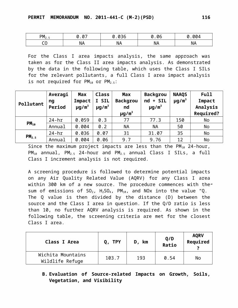
MAJOR SOURCE STANDARD CONDITIONS July 21, 2009 11
(1) Persons opening appliances for maintenance, service, repair, or disposal must comply with the required practices pursuant to § 82.156;
(2) Equipment used during the maintenance, service, repair, or disposal of appliances must comply with the standards for recycling and recovery equipment pursuant to § 82.158;
(3) Persons performing maintenance, service, repair, or disposal of appliances must be certified by an approved technician certification program pursuant to § 82.161;
(4) Persons disposing of small appliances, MVACs, and MVAC-like appliances must comply with record-keeping requirements pursuant to § 82.166;
(5) Persons owning commercial or industrial process refrigeration equipment must comply with leak repair requirements pursuant to § 82.158; and
(6) Owners/operators of appliances normally containing 50 or more pounds of refrigerant must keep records of refrigerant purchased and added to such appliances pursuant to § 82.166.
SECTION XXI. TITLE V APPROVAL LANGUAGE
A. DEQ wishes to reduce the time and work associated with permit review and, wherever it is not inconsistent with Federal requirements, to provide for incorporation of requirements established through construction permitting into the Source’s Title V permit without causing redundant review. Requirements from construction permits may be incorporated into the Title V permit through the administrative amendment process set forth in OAC 252:100-8-7.2(a) only if the following procedures are followed:
(1) The construction permit goes out for a 30-day public notice and comment using the procedures set forth in 40 C.F.R. § 70.7(h)(1). This public notice shall include notice to the public that this permit is subject to EPA review, EPA objection, and petition to EPA, as provided by 40 C.F.R. § 70.8; that the requirements of the construction permit will be incorporated into the Title V permit through the administrative amendment process; that the public will not receive another opportunity to provide comments when the requirements are incorporated into the Title V permit; and that EPA review, EPA objection, and petitions to EPA will not be available to the public when requirements from the construction permit are incorporated into the Title V permit.
(2) A copy of the construction permit application is sent to EPA, as provided by 40 CFR § 70.8(a)(1).
(3) A copy of the draft construction permit is sent to any affected State, as provided by 40 C.F.R. § 70.8(b).
(4) A copy of the proposed construction permit is sent to EPA for a 45-day review period as provided by 40 C.F.R.§ 70.8(a) and (c).
(5) The DEQ complies with 40 C.F.R. § 70.8(c) upon the written receipt within the 45-day comment period of any EPA objection to the construction permit. The DEQ shall not issue the permit until EPA’s objections are resolved to the satisfaction of EPA.
(6) The DEQ complies with 40 C.F.R. § 70.8(d).(7) A copy of the final construction permit is sent to EPA as provided by 40 CFR § 70.8(a).(8) The DEQ shall not issue the proposed construction permit until any affected State and
EPA have had an opportunity to review the proposed permit, as provided by these permit conditions.
MAJOR SOURCE STANDARD CONDITIONS July 21, 2009 12
(9) Any requirements of the construction permit may be reopened for cause after incorporation into the Title V permit by the administrative amendment process, by DEQ as provided in OAC 252:100-8-7.3(a), (b), and (c), and by EPA as provided in 40 C.F.R. § 70.7(f) and (g).
(10) The DEQ shall not issue the administrative permit amendment if performance tests fail to demonstrate that the source is operating in substantial compliance with all permit requirements.
B. To the extent that these conditions are not followed, the Title V permit must go through the Title V review process.
SECTION XXII. CREDIBLE EVIDENCE
For the purpose of submitting compliance certifications or establishing whether or not a person has violated or is in violation of any provision of the Oklahoma implementation plan, nothing shall preclude the use, including the exclusive use, of any credible evidence or information, relevant to whether a source would have been in compliance with applicable requirements if the appropriate performance or compliance test or procedure had been performed.
[OAC 252:100-43-6]