Embed Size (px)
Citation preview

DISTRIBUTION SHEET To From
D. R. Phi l l i p j Page 2 of 2
D i s t r i bu t i on
From
D. R. Phi l l i p j Date 11/30/94 Project Title/Work Order
f o r Project W-320, Tank . 241-C-106 EDT No. N/A
Project Management Plan f o r Project W-320, Tank . 241-C-106 ECN No. W320-56 Slu ic ing
Text With
Text Only
Attach. /
EDT/ECN Only
Name MSIN All Appendi Attach X
Only T. N. Shaw S6--12 X E. J . Shen S4--58 X M. R. Showalter S6--12 X R. T. Skamser S6--12 X M. R. Snyder S6--12 X G. A. Symons S6--12 X J . A. Yount L5--08 X Central F i les ( o r i g . +2) L8--04 X OSTI (2) L8--07 X Project F i les Rl--28 X Unclassi f ied Document Control A4--18 X
A-6000-135 (01/93) UEF067
OJSTRJBUTION OF THIS UOUUI 1LNI IS UNLIMITED

DISCLAIMER
Portions of this document may be illegible in electronic image products. Images are produced from the best available original document.

DISTRIBUTION SHEET To From Page 1 of 2
D i s t r i bu t i on D. R. P h i l l i p s Date 11/30/94
Project Title/Work Order EDT No. N/A Project Management Plan fo r Project W-320, Tank 241-C-106 Slu ic ing
ECN No. W320-56
Name MSIN
Text With All
Attach
Text Only
Attach. /
Appendi X
Only
EDT/ECN Only
U.S. Department of Energy, Richland Operations Office T. R. Hoertkorn S7-52 X A. G. Lassi la S7-52 X B. L. N ico l l S7-53 X W. R. Wrzesinski S7-53 X B. J . Harp S7-52 X R. L. Long S7-52 X
ICF Kaiser Hanford Company
F. W. Bradshaw S3-07 X W. D. Gallo S3-07 X K. L. Kehler S5-50 X D. J . Shrimpton S3-10 X
Westinqhouse Hanford Company
S6-12 E. G. A l len S6-12 X C. A. Augustine S6-12 X J . W. Bailey S6-12 X J . R. Bellomy S6-12 X D. J . Bishop S6-12 X D. E. Bowers S6-01 X F. E. Boyd S6-12 X D. A. Carter S6-12 X K. B. Ferlan S6-12 X J . P. Harr is S6-12 X C. J . Harden S6-12 X W. M: Harty S6-12 X J . L. Hull S6-12 X J . J . Huston S6-12 X M. N. Islam R3-08 X W. M. Lane S6-12 X T. H. May S6-12 X L. B. McDaniel S6-12 X W. P. McKenna S6-12 X S. R. Nelson G6-14 X D. R. P h i l l i p s S6-12 X D. C. Ramsower S6-12 X J . R. Roberts S6-12 X
A-6000-135 (01/93) WEF067

ENGINEERING CHANGE NOTICE Page 1 of
1. ECN *>8OT4$ Proj. ECN W320-56
2. ECN Category (mark one)
Supplemental [] Direct Revision [X] Change ECN [] Temporary [] Standby [] Supersedure [] Cancel/Void [3
3. Originator's Name, Organization, MSIN, and Telephone No. D.R. Phillips, SST Retrieval Projects, S6-12, 376-4837
Project Title/No./Work Order No. Project W-320
. Document Numbers Changed by this ECN (includes sheet no. and rev.) p, WHC-SD-W320-PMP-001, REV. #&
6. Bldg./Sys./Fac. No. 241-C-106
9. Related ECN N o ( s ) .
P^ N/A _
4. Date
11/30/94
7. Approval Designator 3L
10. Related PO No.
N/A 11a. Modification Work
[] Yes (fill out Blk. 11b)
[X] No (NA Blks. 11b, 11c, 11d)
11b. Work Package No. N/A
11c. Modification Work Complete
N/A
Cog. Engineer Signature & Date
11d. Restored to Original Condition (Temp, or Standby ECN only) N/A
Cog. Engineer Signature & Date 12. Description of Change Editorial Changes and Additions to: Pages: i, iv, 1-2, 3-4 (Figure 3-3), 3-5, 3-10 (Table 3-1), 3-14, 3-15 (Figure 3-4),
3-18, 3-19, 3-20 (Figure 3-5), 3-21, 4-2 (Figure 4-1), 4-3, 4-4, 5-1, 5-3, 6-1. 6-3, 6-4, 6-5, 6-7, C-2, C-ll, C-12, D-6, F-4, F-8, F-9, F-ll, F-13.
Addition of Appendix-K (Construction Plan)
13a. Justification (mark one) As-Found
Criteria Change [ X ] [1 Facilitate Const. [1
Design Improvement T "1 Const. Error/Omission ["]
Environmental J"J Design Error/Omission T 1
13b. Justification Details Updated Organizational graphs and verbage throughout the document to support responsibility changes within SST Retrieval Projects and ICF Kaiser, updated Appendix-F WBS and dictionaries, Updated responsibility assignment matrix, and added Appendix-K (Construction Plan).
14. Distribution (include name, MSIN, and no. of copies) Please see attached Distribution Sheet
RELEASE STAMP
OFFiOIAI P RV \A/f- ! \ y
DATE 0£C 1 h 1394
J&±
A-7900-013-1 (06/92)
ENGINEERING CHANGE NOTICE Page 2 of 2
1. ECN (use no. from pg. 1)
W320-56 15. Design
Verification Requi red [] Y e s
[X] Ho
16. Cost Impact ENGINEERING
Additional M N//\ Savings [] N/A
CONSTRUCTION Additional Savings
N/A N/A
17. Schedule Impact (days)
Improvement j"| \\/f\ D e l a / [ ] N/A
18. Change Impact Review: that will be affected
SDD/DD
Functional Design Criteria
Operating Specification
Criticality Specification
Conceptual Design Report
Equipment Spec.
Const. Spec.
Procurement Spec.
Vendor Information
OM Manual
FSAR/SAR
SafetY Equipment List
Radiation Work Permit
Environmental Impact Statement
Environmental Report
Environmental Permit
Ind icate the re la ted documents (other than by the change described in Block 12. Enter
Seismic/Stress Analysis
Stress/Design Report
Interface Control Drawing
Calibration Procedure
Installation Procedure
Maintenance Procedure
Engineering Procedure
Operating Instruction
Operating Procedure
Operational Safety Requirement
IEFD Drawing
Cell Arrangement Drawing
Essential Material Specification
Fac. Proc. Samp. Schedule
Inspection Plan
Inventory Adjustment Request
the the
engineering documents identified on Side 1) affected document number in Block 19.
Tank Calibration Manual Health Physics Procedure
Spares Multiple Unit Listing
Test Procedures/Specification
Component Index
ASME Coded Item
Human Factor Consideration
Computer Software
Electric Circuit Schedule
ICRS Procedure
Process Control Manual/Plan
Process Flow Chart
Purchase Requisition
Tickler File
19. Other Affected Documents: (NOTE: Documents listed below will not be revised by this ECN.) Signatures below indicate that the signing organization has been notified of other affected documents listed below.
Document Number/Revision Document Number/Revision Document Number Revision N/A
20. Approvals Si gnat
OPERATIONS AND ENGINEERING Cog. Eng. D.R. Phi Hi Cog. Mgr. T.N. Shaw QA J.J. Huston Safety M.N. Islam Environ. N/A Other:
SST Proj. J.P. Harris SST Proj. D.A. Carter SST Proj Mgr. C.A. AugW
PS QuoN^fc^fikU^
Date Signature ARCHITECT-ENGINEER
<Z-P-?f
Date
Environ. N/A
Other:
ICt-JClLProj. Mgr. F.W. Bradshaw
DEPARTMENT OF ENERGY /Z//z/'f'<l— Signature or a Control Number that *y *-rrr~ tracks the Approval Signature
N/A ADDITIONAL N/A
A-7900-013-3 (06/94) GEF096
RELEASE AUTHORIZATION
Document Number: WHC-SD-W320-PMP-001, REV 3
Document Title: Project Management Plan fo r Project W-320, Tank 241-C-106 Slu ic ing
Release Date: 12/14/94
This document was reviewed following the procedures described in WHC-CM-3-4 and is:
APPROVED FOR PUBLIC RELEASE
WHC Information Release Administration Specialist:
J~LsC£~Z December 14, 1994 ara M. Broz
TRADEMARK DISCLAIMER. Reference herein to any specific commercial product, process, or service by trade name, trademark, manufacturer, or otherwise, does not necessarily constitute or imply its endorsement, recommendation, or favoring by the United States Government or any agency thereof or its contractors or subcontractors. This report has been reproduced from the best available copy. Available in paper copy and microfiche. Printed in the United States of America. Available to the U.S. Department of Energy and its contractors from:
U.S. Department of Energy Office of Scientific and Technical Information (OSTI) P.O. Box 62 Oak Ridge, TN 37831 Telephone: (615) 576-8401
Available to the public from: U.S. Department of Commerce National Technical Information Service (NTiS) 5285 Port Royal Road Springfield, VA 22161 Telephone: (703) 487-4650
A-6001-400.2 (09/94) WEF256

^ 6 5 SUPPORTING DOCUMENT 1 . Tot a t 'wsstepfe??
iw Title
Project Management Plan for Project W-320, Tank 241-C-106 Sluicing
3. Number
WHC-SD-W320-PMP-001 4. Rev No.
3
5. Key Words Sluicing, Project Management
6. Author
Name: D.R. PHILLIPS
APPROVED FOF "i kba^&^BkjJ.Lfis,
*„* "tf//(/ PUBLIC RELEASE Signature
Organization/Charge Code 7F840/D2MA1
7. Abstract This Project Management Plan establishes the organization, plans, and systems for management of Project W-320 as defined in DOE Order 4700.1, Project Management System (DOE 1987).
gURPOSE AND USE OF DOCUMENT - This document was prepared taf^use wittnqthe U.S. Department of Energy and its contractors^"*^ is to be use2T*s<)nly to perform, direct, or integra>erwork under U.S. DepartmeTtfcsftf Energy contracts. This docujuentis not approved for public release'tmtil reviewed. PATENT STATUS - This documertK^fiMSyT^ since it is transmitted in advance of patent clearar«:e^**"'mad>N3vailable in confidence solely for use in performaja«eof work t3Tid«icontracts with the U.S. Department of^rte*fgy. This document is M M o b e published nor its contentsoth^rwise disseminated or used for purjfesesother than specif iecLreSove before patent approval for such releaseo>S4se has been,»e€ured, upon request, from the Patent Counsel, U.S. Depart!
Energy Field Office, Richland, WA. DISCLAIMER - This report was prepared as an account of work sponsored by an agency of the United States Government. Neither the United States Government nor any agency thereof, nor any of their employees, nor any of their contractors, subcontractors or their employees, makes any warranty, express or implied, or assumes any legal liability or responsibility for the accuracy, completeness, or any third party's use or the results of such use of any information, apparatus, product, or process disclosed, or represents that its use would not infringe privately owned rights. Reference herein to any specific commercial product, process, or service by trade name, trademark, manufacturer, or otherwise, does not necessarily constitute or imply its endorsement, recommendation, or favoring by the United States Government or any agency thereof or its contractors or subcontractors. The views and opinions of authors expressed herein do not necessarily state or reflect those of the United States Government or any agency thereof.
9. Impact Level S Q
10. RELEASE STAMP
A-6400-073 (11/91) <EF> WEF124

RECORD OF REVISION (1) Document Munber
UHC-SD-U320-PHP-001 Page 1
(2) T i t l e ! Project Management Plan for Project W-320, Tank 241-C-106 Sluicing
CHANGE CONTROL RECORD
(A) Description of Change - Replace, Add, and Delete Pages Author ized f o r Release (3) Revision (A) Description of Change - Replace, Add, and Delete Pages
(5) Cog. Engr. (6) Cog. Hgr. Date
(7)
0 Released per EDT 601745, dated 03/01/94 DR Phi l l ips HR Gouqe 1 RS Per Project ECN W320-21,
Editor ia l changes and Appendix J addition
DR Phi l l ips HR Gouge
2 % Per Project'ECN W320-34, E d i t o r i a l changes DR Phi 11 IDS HR Goune l^^P^f* and addi t ions to the f o l l ow ing : /- /?/ ,f /^ <?
Paqe: 3-4, 3-7, 3-10, 3 -11 , 3-15, 3-16,
4 -2 , 4 -3 , 4 -4 , D-4, D-6
ADDendix - E: Add i t i on , E-l th ru E-10 ADDendix - F: F-5, F-8, F-9, F - l l , F-13 Quae
3 RS Per Project ECN W320-56, Ed i to r i a l changes DR P h i l l i p s f TN S h a w / ^ / ^ . . and addit ions to the fo l l ow ing : Page: i , i v , 1-2, 3-4, 3-5, 3-10, 3-14, 3-15
3-18, 3-19, 3-20, 3-21, 4-2 , 4-3, 4-4 5 - 1 , 5-3, 6 - 1 , 6-3, 6-4, 6-5, 6-7, C-2, C - l l , C-12, D-6, F-4, F-8, F-9, F - l l ,
F-13. Appendix - K: Addit ion Kl - K16
,
.

WHC-SD-W320-PMP-001 Revision 3
PROJECT MANAGEMENT PLAN FOR PROJECT W-320, TANK 241-C-106 SLUICING
December 1994 Prepared for
Tank Waste Projects Division, U.S. Department of Energy, Richland Operations Office
by Single-Shell Tank Retrieval Projects
Westinghouse Hanford Company
WESTINGHOUSE HANFORD COMPANY APPROVAL:
C. A Single-Shel
Augustine, Manager rTank Retrieval Projects
/Z-/4-9? Date
i

WHC-SD-W320-PMP-001 Revision 3
This page intentional ly l e f t blank.
i i

WHC-SD-W320-PMP-001 Revision 3
CONTENTS
1.0 INTRODUCTION 1-1 2.0 OBJECTIVES 2-1
2.1 TECHNICAL OBJECTIVES 2-1 2.2 ENVIRONMENTAL, SAFETY, AND HEALTH PROTECTION 2-2 2.3 QA 2-2 2.4 SCHEDULE 2-3 2.5 COST 2-3 2.6 STAFFING 2-3
3.0 MANAGEMENT ORGANIZATION AND RESPONSIBILITIES 3-1 3.1 ORGANIZATION 3-1
3.1.1 DOE 3-1 3.1.2 Contractors 3-1
3.2 PROJECT PARTICIPANT RESPONSIBILITIES 3-5 3.2.1 DOE 3-5 3.2.2 WHC 3-14 3.2.3 ICF KH 3-19
4.0 WBS 4-1 5.0 SYSTEMS ENGINEERING MANAGEMENT 5-1 6.0 PROJECT MANAGEMENT SYSTEM 6-1
6.1 PROJECT MANAGEMENT SYSTEM DOCUMENTATION . 6-2 6.2 BASELINE MANAGEMENT 6-2
6.2.1 Scope Baseline Control 6-2 6.2.2 Schedule Baseline Control 6-4 6.2.3 Cost Baseline Control . 6-5 6.2.4 Funds Management 6-6 6.2.5 MR . . . . 6-7 6.2.6 Contingency 6-7
6.3 PROJECT WORK AUTHORIZATION 6-7 6.4 PROJECT PERFORMANCE MEASUREMENT AND CONTROL 6-8 6.5 PROJECT STATUS, MANAGEMENT REPORTING, AND MANAGEMENT
REVIEWS 6-9 7.0 REQUIREMENTS MATRIX 7-1 8.0 REFERENCES 8-1 9,0 GLOSSARY GL-1
iii

WHC-SD-W320-PMP-001 Revision 3
CONTENTS (cont)
APPENDIXES: A PROJECT W-320 PROJECT MANAGEMENT PLAN, ADVANCE ACQUISITION OR
ASSISTANCE PLAN A B PROJECT W-320 PROJECT MANAGEMENT PLAN, TEST AND EVALUATION
PLAN . • B C PROJECT W-320 PROJECT MANAGEMENT PLAN, ENVIRONMENTAL, SAFETY,
AND HEALTH PROTECTION IMPLEMENTATION PLAN C D MEMORANDUM OF UNDERSTANDING BETWEEN THE MANAGER, SINGLE-SHELL TANK
RETRIEVAL PROJECTS; THE MANAGER, EAST TANK FARMS OPERATIONS; AND THE MANAGER, COMPLIANCE, SAMPLING, AND SUPPORT OPERATIONS FOR PROJECT W-320, TANK 241-C-106 SLUICING D
E PROJECT W-320 PROJECT MANAGEMENT PLAN, CONFIGURATION MANAGEMENT PLAN . E
F PROJECT W-320 PROJECT MANAGEMENT PLAN, PROJECT-SPECIFIC WORK BREAKDOWN STRUCTURE DICTIONARIES F
G PERMITTING PLAN FOR PROJECT W-320, TANK 241-C-106 WASTE RETRIEVAL SLUICING SYSTEM G
H ENVIRONMENTAL ASSESSMENT, TANK 241-C-106 PAST-PRACTICE SLUTCING WASTE RETRIEVAL DOE/EA-XXXX •. H
I PROJECT W-320 PROJECT MANAGEMENT PLAN, STARTUP AND OPERATIONS TRAINING PLAN I
J PROJECT W-320 PROJECT MANAGEMENT PLAN, QUALIFICATION AND TRAINING PLAN J
K PROJECT W-320 CONSTRUCTION PLAN K
iv

WHC-SD-W320-PMP-001 Revision 3
LIST OF FIGURES
3-1 U.S. Department of Energy-Headquarters Program and Project Organization 3-2
3-2 U.S. Department of Energy, Richland Operations Office Organization . 3-3 3-3 Matrix Relationships 3-4 3-4 Single-Shell Tank Retrieval Projects Organization 3-15
3-5 ICF Kaiser Hanford Company Organization 3-20 4-1 Work Breakdown Structure 4-2 5-1 U.S. Department of Energy Order 4700.1 Systems Engineering
Process 5-2
LIST OF TABLES
3-1 Tank 241-C-106 Sluicing Responsibility Assignment Matrix 3-6 4-1 Project W-320 Project-Specific Work Breakdown Structure 4-3 4-1 Project W-320 Project-Specific Work Breakdown Structure . . . . . . 4-4 6-1 Summary of Baseline Information 6-3
, 6-2 Summary of Change Control Thresholds 6-4 7-1 U.S. Department of Energy Order 4700.1 and Project Management
Plan Matrix . 7-2
v

WHC-SD-W320-PMP-001 Revision 3
This page intent ional ly l e f t blank.
vi

WHC-SD-W320-PMP-001 Revision 3
PROJECT MANAGEMENT PLAN FOR PROJECT W-320, TANK 241-C-106 SLUICING
1.0 INTRODUCTION
A major mission of the U.S. Department of Energy (DOE) is the permanent disposal of Hanford Site defense wastes by utilizing safe, environmentally acceptable, and cost-effective disposal methods that meet applicable regulations.
The Tank Waste Remediation System (TWRS) Program was established at the Hanford Site to manage and control activities specific to the remediation of safety watch list tanks, including high-heat-producing tanks, and for the ultimate characterization, retrieval, pretreatment, and disposal of the low-and high-level fractions of the tank waste.
Project W-320, Tank 241-C-106 Sluicing, provides the methodology, equipment, utilities, and facilities necessary for retrieving the high-heat waste from single-shell tank (SST) 241-C-106. Project W-320 is a fiscal year (FY) 1993 expense-funded major project, and has a design life of 2 years including 1 year of retrieval operations.
Retrieval of the waste in tank 241-C-106 will be accomplished through mobilization of the sludge into a pumpable slurry using past-practice sluicing. The waste is then transferred directly to a double-shell tank (DST) for interim storage, subsequent pretreatment, and eventual disposal.
The following will be participants in Project W-320 activities. A detailed description of the management organization and responsibilities is presented in Section 3.0.
. DOE - DOE-Headquarters (HQ) Program Manager
TWRS Division - DOE, Richland Operations Office, RL Program Manager
Office of Tank Waste Disposal (RL TWD)
- RL Office of Tank Waste Projects Project Manager (RL TWP)
• Westinghouse Hanford Company (WHC) - TWRS Projects Integrating Contractor (IC)
1-1 QISTBiBUTION OF. THIS DOCUMENT IS UNLIMITtu

WHC-SD-W320-PMP-001 Revision 3
• ICF Kaiser Hanford Company (ICF KH) - Engineering Division/ Onsite Engineering/
Construction Management Division Construction Contractor (E/C)
This Project Management Plan (PMP) establishes the organization, plans, and systems for management of this project as defined in DOE Order 4700.1, Project Management System (DOE 1987). Implementing procedure DOE RLIP 4700.1A (DOE-RL 1991) has defined general requirements for project management systems. This PMP, prepared in accordance with the requirements of WHC-CM-6-2, Project Management, Section PM-7, "Project Management Plan," provides project-specific strategies and direction. This PMP supplements the approved SPP (RL 1993).
The project technical, cost, and schedule baselines are provided for in accordance with the approved FDC and engineering study letter report, and are described in Section 2.0 of this document. These baselines are summarized in the SPP. The environmental, safety, and health protection objectives, along with quality assurance (QA) requirements, also are described in Section 2.0. Organizational roles and responsibilities and management system policies are outlined in Section 3.0. The project work breakdown structure (WBS) is described in Section 4.0. Systems engineering management is described in Section 5.0. Section 6.0 describes the project management and control system. Section 7.0 provides a requirements matrix. Advance Acquisition or Assistance Plans are provided in Appendix A. Test and Evaluation Program Plans are detailed in Appendix B. Environmental, Safety, and Health Protection Plans are provided in Appendix C. Division of responsibility between projects and operations is provided in Appendix D. The Configuration Management Plan and Work Breakdown Dictionaries are provided in Appendixes E and F, respectively. Project Permitting Plans are provided in Appendix G. National Environmental Policy Act documentation is provided in Appendix H. Project Training Program Plans are detailed in Appendix I. The Qualification and Training Plan is presented in Appendix J. The Construction Plan is provided in Appendix K.
This PMP will be updated as required to incorporate changes resulting from project evolution or redirection. Revision to this PMP will result in either an individual page change or in the complete reissuance of the PMP depending on the scope of the change.
Significant project documents are as follows: . WHC-SD-WM-ES-234, Letter Report, Tank 241-C-106 Sluicing
Project W-320 (WHC 1993)
• WHC-SD-W320-FDC-001, Functional Design Criteria for Tank 241-C-106 Haste Retrieval, Project W-320 (Bailey 1994)
• "Tank 241-C-106 Sluicing Project Justification of Mission Need" (Lytle 1993)
• "Tank 241-C-106 Sluicing Project, Summary Project Plan" (RL 1993) . WHC-SD-W320-QAPP-001, Project-Specific Quality Assurance Plan
(Huston 1993).
1-2

WHC-SD-W320-PMP-001 Revision 3
2.0 OBJECTIVES
2.1 TECHNICAL OBJECTIVES Tank 241-C-106 is a 2,006,050-L- (530,000-gal-) capacity SST located in
the C Tank Farm in the 200 East Area of the Hanford Site. The tank has been used for radioactive waste storage since 1947. In the 1960's, tank 241-C-106 received high-level, strontium-bearing solids. In 1971, temperatures exceeding 99 °C (210 °F) were observed in the tank. To prevent the sludge from drying out and the tank from overheating, approximately 22,710 L (6,000 gal) of cooling water are added to the tank each month. The radioactive decay heat is removed by evaporative cooling of the waste. Tank 241-C-106 was withdrawn from active service in 1979 and is categorized as sound (i.e., not known to be leaking); however, the tank has the potential to start leaking at any time.
The high-heat waste stored in tank 241-C-106 has been identified as the fourth Priority 1 safety issue at the Hanford Site because of the requirement to continue the cooling water additions. If the cooling water additions were stopped, the tank temperatures would exceed current limits with the potential for structural failure of the tank. If the tank were to start leaking, cooling water additions would be continued to prevent structural damage.
In addition, the Hanford Federal Facility Agreement and Consent Order (Ecology et al. 1994) (also known as the Tri-Party Agreement), Milestone M-45-03, October 1997, requires initiation of waste retrieval from one Hanford Site SST as a demonstration of SST retrieval technology. The DOE has identified tank 241-C-106 as the M-45-03 retrieval demonstration tank. Washington State Department of Ecology has concurred with this selection.
The goals of Project W-320 are to retrieve the high-heat waste from tank 241-C-106, close the safety issue associated with the tank, and demonstrate initial waste retrieval technology for an SST.
Project W-320 will prepare tank 241-C-106 for waste retrieval, and prepare tank 241-AY-102 as the DST to receive the waste. The specific technical objectives are as follows.
• Provide retrieval equipment, ventilation systems, electrical distribution upgrades, waste transfer lines, and other equipment required to retrieve the waste from tank 241-C-106.
• Upgrade and modify tank farm utilities as required to facilitate retrieval operations.
• Protect the environment from the spread of contaminants during tank upgrades and retrieval operations, in accordance with the requirements of applicable regulations and agreements and commitments with regulatory agencies.
The scope of Project W-320 includes the removal and packaging of existing pumps in tanks 241-C-106'and 241-AY-102; the equipment specific to retrieval of waste tank contents; all supporting structures; facilities (including
2-1

WHC-SD-W320-PMP-001 Revision 3
control room); waste tank modifications; receiver tank system modifications necessary to receive tank 241-C-106 waste; the new, temporary, buried encased transfer line to and from the DST system; and all associated support equipment.
Detailed technical design criteria, functions, and standards for Project W-320 are provided in the FDC (Bailey 1994).
2.2 ENVIRONMENTAL, SAFETY, AND HEALTH PROTECTION This project will comply with all applicable federal, state, and local
environmental laws and regulations, including applicable waste volume reduction requirements and those covering gaseous, liquid, or solid effluents such as the Clean Air Act of 1955 (CAA); National Environmental Policy Act of 1969 (NEPA); and WAC 173-303, "Dangerous Waste Regulations."
It is the policy of WHC to comply with all applicable DOE Orders, policies, and requirements in the area of safety. The responsibility for developing and implementing an effective safety program begins at the highest levels of the DOE and WHC line management and rests with all elements of the organization. This responsibility includes establishing a work environment that encourages individual awareness, participation, and responsibility for safety. This approach establishes safety as the highest priority for all work activities, encourages active review and participation in the safety process, and assigns accountability throughout all levels of the project organization.
Project W-320 activities will be conducted in compliance with federal, state, and local regulations, laws, and standards for the protection of the environment, and the safety and health of the employees and the public. The policy for nuclear safety is provided in Secretary of Energy Notice 35-91, Nuclear Safety Policy (DOE 1991a).
2.3 QA Quality assurance activities for all contractors involved in the design,
construction, inspection, testing, and acceptance of Project W-320 will be formulated and executed by the IC to provide assurance that Project W-320 is designed and constructed as intended. The QA requirements will be in accordance with DOE Order 5700.6C, Quality Assurance (DOE 1991b). These requirements will be implemented in a graded approach, as defined in DOE Order 5700.6C.
An effective quality plan for Project W-320 is established through WHC-SD-W320-QAPP-001, ProjecUSpecific Q'-^lity Assurance Plan (Huston 1993). The QA program will be implemented by the IC to ensure a requisite level of quality, safety, and environmental compliance in all areas of design, construction, test, and evaluation. Specific QA program objectives for all TWP, including Project W-320, will be described in TWP documents.
2-2

WHC-SD-W320-PMP-001 Revision 3
2.4 SCHEDULE The overall objectives, based on the SPP, are depicted in the approved
project master schedule. This schedule supports Tri-Party Agreement Milestone M-45-03, "Initiate Sluicing Retrieval of C-106." Project W-320 has been identified as Hanford Site Safety Initiative 6, "Accelerate retrieval of high-heat tank 241-C-106." The safety initiative requires initiation of waste retrieval from tank 241-C-106 on an accelerated basis with retrieval operations starting by October 1996. Changes to the approved master schedule will be made to support the Hanford Site safety initiative.
2.5 COST The capital-versus-expense determination ruling recommends funding all
tasks using a combination of expense and capital equipment not related to construction (CENRTC). The cost objective is to complete Project W-320 within a total project cost (TPC) as defined by the current project authorization.
The current budget requirements for Project W-320 for CENRTC and expense will be updated annually in the budget submittal and corresponding Project Data Sheet.
2.6 STAFFING Onsite Operations and Maintenance Contractor (WHC) staffing will be used
for expense and CENRTC items. Onsite E/C (ICF KH) staffing also will be used for CENRTC and expense design and construction work. The IC staff will be managed through use of an RL-approved earned value system using cost accounts to manage each work activity. The ICF KH staffing will be managed through a work order system and controlled via an approved earned value reporting system.
2-3

WHC-SD-W320-PMP-001 Revision 3
This page intent ional ly l e f t blank.
2-4

WHC-SD-W320-PMP-001 Revision 3
3.0 MANAGEMENT ORGANIZATION AND RESPONSIBILITIES
3.1 ORGANIZATION The following is an organizational description of the participants for
Project W-320. The project participants consist of DOE-HQ; RL; and two RL contractors, WHC and ICF KH. Matrix support is provided by RL and WHC matrix organizations.
3.1.1 DOE 3.1.1.1 DOE-HQ. The responsibilities of DOE-HQ for Project W-320 have been assigned to the TWRS Division (EM-361) within the Office of Hanford Programs (EM-36) under the Deputy Assistant Secretary for Waste Management (EM-30) and the Assistant Secretary for Environmental Restoration and Waste Management (EM-1). Figure 3-1 details the DOE-HQ organization related to Project W-320. 3.1.1.2 RL TWP Division. The manager of RL has assigned the management responsibility for TWP to the Office of Tank Waste Projects of the TWRS Program Office. The responsibilities for program direction have been assigned to the Office of Tank Waste Retrieval, Treatment, and Immobilization. The RL organization related to Project W-320 is detailed in Figure 3-2. The RL matrix organizations providing support to the RL TWRS Program Office are detailed in Figure 3-3; their functions are described in Section 3.2.1.3.
3.1.2 Contractors 3.1.2.1 WHC.
3.1.2.1.1 TWRS. The WHC TWRS operates all facilities associated with the processing, storage, and disposal of defense wastes at the Hanford Site. Responsibilities for Project W-320, within WHC, have been assigned to the Single-Shell Tank Retrieval Projects (SSTRP) organization within the TWRS Projects Division. Matrix organizational support is provided by WHC's Engineering, Safety, QA, and Regulatory and Environmental organizations. Figure 3-3 identifies the major matrix organizations providing support to WHC SSTRP, and Section 3.2.2.2 describes their functions.
3.1.2.1.2 WHC SSTRP Organization. The SSTRP, as the IC within WHC TWRS, implements the project management function for the RL TWP Office with overall technical direction, coordination, baseline control, integration, QA, applied technology, regulatory compliance, and startup activities for Project W-320.
Project W-320 uses the concept of an integrated management team (IMT) to execute required project tasks. The following contractors are the major project participants to the IMT:
• IC--WHC • Engineering—ICF KH, with support from WHC for equipment removal
systems and waste packaging
3-1

WHC-SD-W320-PMP-001 Revision 3
Figure 3-1. U.S. Department of Energy-Headquarters Program and Project Organization.
Assistant Secretary for Environmental Restoration and Waste Management
EM-1
Office of Waste Management EM-30
Deputy Assistant Secretary
Office of Hanford Programs EM-36
Director
Tank Waste Remediation System Division EM-361 Director
Tank Waste Remediation System Division EM-361
Program Office
34 0203-1 .CH3 02-14-94
3-2

WHC-SD-W320-PMP-001 Revision 3
Figure 3-2. U.S. Department of Energy, Richland Operations Office Organization.
U.S. Department of Energy, Richland Operations Office
Office of the Manager
Principal Deputy Manager
Tank Waste Remediation System Program Office
(TWR)
Program Manager
Office of Tank Waste Retrieval, Treatment, and Immobilization
Director
Office of Tank Waste Projects <TWP)
Director
Program Manager Projects Branch
Chief
Project W-320
940203-2.CH3 02-14-94
3-3

Tank Waste Remediation System Program Office
U.S. Department of Energy-Headquarters
Office of Tank Waste Projects
U.S. Department of Energy, Richland Operations Office
CO i
Office of Tank Wast* Retrieval, Treatment, »nd
Immobilization
RL Site Infrastructure Division
RL Program Support Division Technical Support Branch
RL Procurement Division
RL Technical Support Division Occupational
Safety Branch
Single-Shell Tank Retrieval Projects
Westlnghouse Hanford Company
WHC TWRS Programs P N L
Safety Support
ICF KH Engineering Construction
Management, Construction Acceptance Inspection
ARES Corporation Project Document
Reviews
Advent Engineering Company
Structural Analysis
CH2M Hill Air Permitting, T-BACT,
and BARCT
Raytheon Corporation Safety Assessment
Procurement
Package Safety Engineering
Package Design Engineering
W H C Engineered Applicat ions
WHC Safety and Quality Assurance
WHC Information Resource Management
c -s (D
to i
CO
OJ <-t-
- s
73 CD _ j
0> c+
O
00
X3
73 CD <
o i
CO
I
co o 1
CO ;
O O
WHC Environmental Division
BARCT « Beet available radionuclide control technology ICF KH = ICF Keleer Hanford Company PNL - Pacific Northwaat Laboratory RL = U.S. Department of Energy, Richland Operatlona Office T-BACT » Beet available control technology for toxtce TWRS • Tank Waate Remediation Syetem WHC • Weattnghouee Hanford Company
WHC Waste Tank Operations
1S0410-1.CH3 11-1*44

WHC-SD-W320-PMP-001 Revision 3
• Construction/construction management—ICF KH, with site access control and coordination with operations by WHC
• Quality performance/assessment—WHC • Environmental/regulatory compl i ance—WHC • Equipment and Systems procurement—WHC • Startup—WHC.
The IMT concept provides flexible and dynamic organizational relationships with total project accountability and responsibility being maintained at the IC level. 3.1.2.2 ICF KH. The ICF KH will be the Architect-Engineer (A-E) performing definitive design. The ICF KH also will perform field engineering during construction as a subcontractor to WHC under a cost plus award fee contract. The detailed design work will provide the design media required for the procurement, construction, and acceptance testing of equipment removal systems and retrieval systems for Project W-320.
Design performed by WHC will be reviewed by ICF KH for equipment removal system interfaces and for constructibility.
ICF KH will be the E/C providing construction and procurement support services. The E/C will have overall responsibility for construction, and construction-related activities for Project W-320. Westinghouse Hanford Company shall procure specialized long lead, engineered process equipment and systems, which consists of equipment specifically designed for a project and not commonly available as standard or catalog equipment. ICF-KH will provide procurement specifications, purchase requisitions, and submittal services to the project.
3.2 PROJECT PARTICIPANT RESPONSIBILITIES Major project functions have been identified and each participant has
been assigned responsibility and direct accountability for performing these functions. Table 3-1 provides a summary of Project W-320 participant responsibilities associated with project activities, tasks, and products. The following discussion identifies, by organization, the roles and responsibilities of Project W-320 participants.
3.2.1 DOE 3.2.1.1 DOE-HQ Branch. The program manager serves as the DOE-HQ contact for the project, and ensures that all required DOE-HQ activities are accomplished. Specific activities include, but are not limited to, the following.
1. Provide programmatic direction, overview, and DOE-HQ coordination. 2. Provide for DOE-HQ approval of the SPP for Project W-320.
3-5

Table 3-1. Tank 241-C-106 Sluicing Responsibility Assignment Matrix, (sheet 1 of 6) Activity task product description Engineering Construction IC RL owner Comments
CO i
Project Management and Integration Project Plan
PSUBS PSWBS dictionary Integration procedure development
Level 0 and 1 change requests
Level 2, 3, and 4 change requests
Other change requests Surveillance of project activities
C, R
P
C, R
R, C
P P P
P, R
P, R
P, A S
P, A
A A A
Final approval obtained at the acquisition executive level in DOE-HQ. Approved as a part of the project plan.
WHC has lead for the development of all integration procedures. Level 0 changes are approved by the acquisition executive. Level 1 changes are approved by the program secretarial officer (contractor preparation and review as applicable). Level 2 changes are approved by RL, Level 3 changes are approved by TWR, and Level 4 changes are approved by TWP (contractor preparation and review as applicable). Level 5 changes are originator controlled.
73 CD <
O 3
Business Hanagemer Contractor work breakdown structure code and dictionary Project master schedules Contractor master schedules Contractor detailed schedules Cost reporting and analysis Document control plan
Records management plan
Contractor work plans Contractor staffing plans
P, A
P, A P. A P, A
P, R P, A, S
P. A, S
A, S A
Approved as a part of the project plan.
Contained in the configuration management plan. Contained in the configuration management plan.

Table 3-1. Tank 241-C-106 Sluicing Responsibility Assignment Matrix, (sheet 2 of 6) Activity task product description Engineering Construction IC RL owner Comments
Monthly/quarterly report to RL Monthly/quarterly report to DOE-HQ Management reports, meetings, and reviews Personnel training and qualification records Project construction cost estimate (TEC/TPC) Subcontracted fair cost estimate Budget Submittal/CPDS
P
P
P. C
P, S
C. A
P, S
R
u> I
Engineering
Prepare and maintcMn FDC Prepare and maintain A-E LOIs Review of design documents OperabiIi ty/ma i nta i nabiIi ty review
P P, A C, A P
CM reviews for constructibility.
7D <
o 3
Design
Design drawings, specifications, and supporting documents for construction procurement packages
Independent design verification
Engineering configuration control A-E training and qualification procedures Facility siting
P, A
P, A
P, A P, A
P, A, S
P, A, S
S S
P, RA
WHC approves for construction. Technical correctness of the ICF KH-produced design requires ICF KH approval. UHC approval required for the functional requirements of the design. ICF KH responsible for design verification of ICF KH-prepared design. WHC responsible for design verification for UHC-produced design.
RL matrix office (Site Infrastructure Division) has final approval.

Table 3-1. Tank 241-C-106 Sluicing Responsibility Assignment Matrix, (sheet 3 of 6) Activity task product description Engineering Construction IC RL owner Comments
I 00
Incorporate results of P, A engineering studies and testing Document basis for design P, A Identify additional verification P testing required Factory acceptance test P, A specification Construction acceptance test P, A specifications Preoperational test C specifications Operational test specifications C Vendor designs A Spare parts requirements P Engineering during construction P, A As-built drawings P, A
R C
C, R C
S, C, P, A
R, A
P, R
R
P, R, A
P. R, A
A, C, S P, A, C
S R, P, A
TO fD <
O 3
Construction
Construction Procurement Preprocurement plans Subcontracted construction specification
Construction work packages Subcontractor plan Site utilization plan Construction permits CM construction procedure Perform constructibility reviews
P P P
P. A
P. A P, A P
P, A P, A P
S S, P A, P S
S, R R S A R
RL approval required only for those contracts that exceed thresholds. Thresholds are defined in ICF KH procedures.
Welding permits, excavation permits, etc.

Table 3-1. Tank 241-C-106 Sluicing Responsibility Assignment Matrix, (sheet 4 of 6) Activity task product description Engineering Construction IC RL owner Comments
i 10
Installation procedures
Care and maintenance instructions
Utility tie-ins Surveys Construction waIkdowns/punch lists Construction support facilities Project security CM emergency plan Labor relations Procurement solicitation packages Vendor qualification Vendor submittals Factory acceptance testing
Construction acceptance test procedures Perform construction acceptance testing
Systems turnover Construction completion report
Startup and Operations
Individual test plans Care and maintenance instructions Operational test procedures Operational tests Test reports
R. C
P, A R
P, A R, S
P, C C, A P P P
P S --P, A P, R S P, A A P C C
P, A S, P, A S P, A S, P, A S P, R R, P, A S A S S
P, A R
P, A S S
P P. C
A
P, A
P, A P, A P, A P, A P, A
R R. S
Developed in accordance with CM technical specifications. During storage and after installation prior to turnover.
Integration of security performed by UHC.
Subcontractor/vendor performs factory acceptance testing. Subcontractors may prepare procedure.
Subcontractor may perform construction acceptance testing. WHC will use test results as one of the bases for system/component acceptance.
RL Project's and Program's approvals required on "Official Acceptance of Construction."
ft) <
o

Table 3-L Tank 24.1-C-106 Sluicing Responsibility Assignment Matrix, (sheet 5 of 6) Activity task product description Engineering Construction IC RL owner
C -- P, A R
C C P, A
P
P, A
S
. . .-
P, A
P
P, A R
Comments Operational readiness review plan Operational readiness review Operator training Startup and operations documentation
QA
Develop QA plan Contractor QA plans QA audits and surveillance of participants Internal QA audits and surveillance Government acceptance inspections
Audit schedule
P, C
P, A P, A P
WHC performs receiving inspections for procurement, not be be confused with government acceptance inspections. ICF KH performs government acceptance inspections.
TO a> <
o 3
P, A
Safety
Independent safety review of design criteria Independent safety review of plant design Safety analysis of plant and process
Preliminary safety evaluation
Construction safety Safety oversight and appraisal of contractor safety programs Preliminary safety equipment list Safety equipment list
C, R
C, R
C, R C, R
P. A P
P. A
P
P, A
P. A
S, P P
P. A P, A
Safety analysis documented in safety assessment. Approval delegated to RL. Approval via Safety Evaluation Report. Approval delegated to RL. Safety Review letter.
Approval via
Part of safety assessment.

Table 3-1. Tank 241-C-106 Sluicing Responsibility Assignment Matrix, (sheet 6 of 6) Activity task product description Engineering Construction IC RL owner Comments Regulatory Compliance
Environmental plan and procedures CAA permits application
RCRA permits application
Prepare environmental documentation
A = ApprovaI A-E = Architect-Engineer C = Contributes input CAA = Clean Air Act CM = Construction Manager CPDS = Construction project data sheet DOE-HQ = U.S. Department of Energy-Headquarters EPA = U.S. Environmental Protection Agency FDC = Functional design criteria IC = Integrating Contractor ICF KH = ICF Kaiser Hanford Company LOI = Letter of instruction NEPA = National Environmental Policy Act of 1969 P = Prepares/provides PSWBS = Project summary work breakdown structure QA = Quality assurance R = Reviews/comments RA = Recommends approval RCRA = Resource Conservation and Recovery Act of 1976 RL = U.S. Department of Energy, Richland Operations Office S = Selected technical surveillance TEC = Total estimated cost TPC = Total project cost TWP = Tank Waste Projects TWR = Tank Haste Remediation WHC = Uestinghouse Hanford Company
C, R C, R P, A C C P, A
C -- P, A
C C P, R, A
A Issued by Washington State and EPA. Permits require approval of owner and operator.
A Issued by Washington State. Permits require approval of owner and operator.
A Approval of NEPA documentation delegated to RL.

WHC-SD-W320-PMP-001 Revision 3
3. Establish and control the overall scope, cost, and schedule envelope for the project, as defined in the SPP.
4. Provide funding required for the design, construction, and startup of the project.
5. Approve changes to DOE-HQ controlled milestones which may impact the project's total estimated cost (TEC) or completion date.
6. Delegate authority to RL for the review, processing, and approval of project Key Decisions 3 and 4, project safety assessment, NEPA documentation, environmental permit applications, and operational readiness reviews (ORR).
3.2.1.2 RL TWP Office. The RL TWP Office is responsible for the management, administration, and performance of Project W-320 in accordance with established technical, cost, and schedule baselines. Specific management, administrative, and technical performance activities include, but are not limited to, the following.
1. Establish a project organization and delegate appropriate authority for execution of the project.
2. Ensure the establishment of the project technical, cost, and schedule baselines and the development and implementation of appropriate project controls for baseline management.
3. Provide overall direction, administration, and performance evaluation of the IC in its management of each project element. Review the IC's QA program plans. Ensure that QA plans and QA implementing procedures meeting DOE policies and requirements ; established and implemented by all project participants, and tf appropriate RL-approved procedures for QA and safety are implemented.
5. Coordinate management reviews, assessments, and audits and/or surveillances of the project elements to ascertain that the project is complying with applicable DOE safety, environmental, QA, programmatic, and engineering standards.
6. Ensure appropriate control of project funding, including project management reserve, within the established thresholds.
7. Provide technical liaison and coordination with the DOE-HQ TWRS Program manac"°r.
8. Provide review, processing, and approval of project Key Decisions 3 and 4, project safety assessment, NEPA documentation, environmental permit applications, PMP, and ORRs.
3-12

i
WHC-SD-W320-PMP-001 Revision 3
3.2.1.3 RL Matrix Organizations. The RL matrix organizations, as required, will provide guidance, support, and required approvals to the RL TWP Office for contractor actions as summarized below.
1. The RL TWRS Program Office, Office of Tank Waste Retrieval, Treatment, and Immobilization, has major responsibilities for tank waste remediation projects including approval of, and changes to, the FDC and operational and programmatic responsibility for Project W-320 following completion of the ORR. The RL Office of Tank Waste Retrieval, Treatment, and Immobilization will also ensure that project startup activities are conducted in a manner consistent with applicable criteria, codes, and standards through project completion. Additionally, the RL Office of Tank Waste Retrieval, Treatment, and Immobilization will participate in an oversite capacity in the ORRs conducted by the IC during the startup test program to ensure adequacy of designs, operations, maintenance, and procedures/documentation.
2. The Site Infrastructure Division provides matrix support in the areas of infrastructure management and BCS Richland, Inc.
3. The Program Support Division-Technical Support Branch within the TWRS Program Office provides overview of the IC's QA/quality control as well as safety and regulatory compliance.
4. The Procurement Division (PRO) is the contracting officer on the DOE prime contracts involved with contract administration. The PRO directs and coordinates procurement management for the contractors.
5. The Technical Support Division-Occupational Safety Branch supports Project W-320 with an overview of environmental, safety, and health policy and standards.
6. The Office of Field Chief Financial Officer supports the project in certification of funds availability, disbursement of allocated funds, and review of contractor accounting programs. This Office also provides support in the IC budget development process for Project W-320.
7. The Human Resources and Planning Division supports the project in personnel matters.
8. The Office of Environmental Assurance, Permits, and Policy supports the project in the implementation of, and compliance with, environmental regulatory requirements and DOE Orders.
3-13

WHC-SD-W320-PMP-001 Revision 3
3.2.2 WHC 3.2.2.1 WHC SSTRP Organization. The WHC SSTRP organization (Figure 3-4) has overall responsibility for project management and integration, business management, engineering and construction management, regulatory compliance, and startup, as well as project integration including business management and E/C management. The WHC SSTRP organization shall ensure the project QA program requirements are distributed to all project participants for implementation. Specific activities in the support and accomplishment of these project functions include, but are not limited to, the following:
1. Retrieval Project Control and Administrative Support a. This group is responsible for planning, estimating, baseline
development/management, financial control and reporting systems, and information in direct support to SSTRP. Direct the activities required for implementing and integrating the project management and financial control systems for the new projects identified by the TWRS Retrieval Program Office.
b. Develop and implement the project management and financial control systems consistent with DOE Orders and WHC policies and procedures.
c. Direct and control the development and integration of project cost and schedule baselines for SSTRP. Coordinate and maintain the project cost estimate and schedule; coordinate associated budget and financial planning activities. Prepare and submit budget planning documents consistent with timing of the DOE budget cycle. Perform scope, schedule, and cost monitoring for all project activities.
d. Develop and implement performance measurement processes to track, evaluate, and report on effectiveness of project activities.
e. Develop, review, and maintain all project documentation, i.e., PMP, systems engineering management plan, project-specific procedures, etc.
f. Provide for the SSTRP reporting inputs to monthly and quarterly DOE project reviews, etc. Prepare consolidated narrative, cost, schedule, funding, and staffing monthly progress reports. Keep the RL TWP Office informed of techn^l, cost, and schedule status and concerns.
g. Establish and control the cost and schedule baselines for Sluicing Retrieval Projects.
h. Develop training plans and a training records system for SST retrieval projects.
3-14

Single-Shell Tank Retrieval Projects
Manager
TWRS Projects QA
Single-Shell Tank Retrieval Projects
Manager
TWRS Projects QA
Single-Shell Tank Retrieval Projects
Manager
Retrieval Project Control and
Administrative Support
Acting Manager
Retrieval Project Engineering
Manager
Retrieval Construction and
Startup
Manager
Management CPDS ccnes
Review Mef sting
Validation Document ICF KH Forecast Baseline Management DOE Reporting Fiscal Year Planning Schedules Change Control
I
Watte Tank Safety
NEPA Document
Air and Water
Permit* Architect-Engineer
WHO Design
Project Criteria/System Engineering Design Reviews NEPA Permits Safety Document CAM Design Technical Direction LOIs/WP Approval Design Scope/Cost/Schedule Control Design Authority
CAM = Cost account manager CM = Construction Manager CPDS = Construction project data sheet DOE = U.S. Department of Energy HPT a Health physics technician ICF KH = ICF Kaiser Hanford Company L.OI - Letter of Instruction NEPA = National Environmental Policy Act QA » Quality Assurance SFDS = Short form data sheet TWRS - Tank Waste Remediation System WHC = WestlnghouBe Hanford Company WP m Work plan
1 1
1 1
1 1
Operation! Support CM HPT»
Construction/Procurement LOIs/WP Approval Equipment Removal and Packaging Access Control Construction Training Construction Scope/Cost/
Schedule Control Startup Plans Startup Procedures Startup Training Startup Materials Operational Readiness Review Operations Interface and Turnover CAM
(5041IM.CHS 11.15-8*

WHC-SD-W320-PMP-001 Revision 3
2. Retrieval Project Engineering Responsible and accountable for all aspects of engineering and design preparation for the tank 241-C-106 retrieval projects, and follow-on SST retrieval projects. a. Develop and approve design criteria. b. Establish project execution strategies, and prepare work scope
directives (letters of instruction [LOI]) for all supporting organizations. Review and approve all work plans submitted by supporting organizations.
c. Participate in design reviews to assess adequacy from a system engineering viewpoint.
d. Direct the preparation of the Environmental documentation, including NEPA, CAA, and Resource Conservation and Recovery Act of 1976 (RCRA) permit applications and modifications as required.
e. Interface with regulatory agencies for review of permit applications and design media, and for resolution of open items during the permitting process.
f. Review and approve all project safety documentation. Provide technical input for preparation of the safety documentation
g. Cost account management - Responsible for development and/or management of cost accounts for assigned tasks. Activities include planning and cost account development, oversight, and statusing.
h. Prepare integrated design plans and schedules which include all project definition, regulatory compliance, construction, and startup interfaces. Make midcourse corrections to divisions of scope, methods of performance, and personnel assignments to accomplish design activities safely, with a quality product, within budget, and on schedule.
i. Establish performance requirements and measurement standards for all design organizations and contractors.
j. Manage cost accounts for project design accounts. k. Provide coordination and integration of IC and A-E design
activities. 1. Overview design optimization efforts from the standpoint of
cost, reliability, maintainability, accuracy, and compliance with applicable codes, standards, and regulations.
m. Approve definitive design for conformance to the design criteria.
3-16

WHC-SD-W320-PMP-001 Revision 3
4. Retrieval Construction and Startup Responsible for all aspects of construction site preparation, equipment removal, procurement, construction, and startup of SST projects; safety on the construction site for all participating contractors, project staff, and operations and maintenance forces. Prepare integrated procurement and construction plans and schedules which include all design and startup interfaces. Establish performance requirements and measurement standards for all construction and startup organizations and contractors to ensure timely completion of planned work. a. Establish the requirements and implement a system for access
and work control during equipment removal, new construction, and startup testing to ensure worker safety and efficient use of project resources.
b. Interface with Tank Farm Operations for concurrence with the work control plans and performance of routine surveillance and maintenance work during construction and startup testing.
c. Perform construction walkdowns, and participate in construction acceptance testing and turnover.
d. Prepare startup test plans and procedures, train startup personnel, and perform the startup (preoperational) tests.
e. Perform maintenance on the completed systems and facility until turnover to Operations.
f. Establish an ORR process for SST waste retrieval projects, and conduct the ORR for hot operations.
g. Establish a training program for all project personnel required to perform project work in the C Farm and the AY Farm. The training program must include hands-on training with mockups or actual retrieval equipment. The training will address all work steps. Ensure that the E/C has a training program and training records system.
h. Provide a cost account manager for project construction and startup accounts.
3.2.2.2 WHC Matrix Support. The WHC matrix organizations, as required will provide guidance, support, and required approvals to WHC TWP for Project W-320 actions as summarized below.
1. The WHC Waste Tank Operations Department provides matrix support in the areas of Plant Engineering, Waste Tanks Environmental Compliance, waste sampling, routine monitoring of tank conditions, water additions, and startup support.
3-17

WHC-SD-W320-PMP-001 Revision 3
The WHC QA organization provides independent review of safety, safeguards, emergency preparedness, and QA activities for all Project W-320 activities. The IC's QA organization shall prepare a plan that defines the project QA program requirements. The plan shall address the DOE Order 5700.6C requirements that are applicable to the project.
The IC's QA organization shall conduct oversight activities (i.e., document reviews, surveillances, and audits) of project participants as necessary to ensure the project QA program requirements have been adequately implemented. This action ensures the requisite deliverables quality of project deliverables, including supporting documentation.
The IC's QA organization shall report quality problems noted during oversight activities to the WHC SSTRP organization for correction and shall ensure timely resolution of these problems and their root causes.
The TWRS Safety organization coordinates independent reviews of safety, safeguards, and emergency preparedness for all Project W-320 activities. These reviews include Nuclear Safety and Industrial Waste Tank Safety Support organizations. The Waste Tank Safety Support organization includes independent reviews by Industrial Safety, Industrial Hygienists, and Fire Protection.
The TWRS Industrial Health and Safety organization prepares the project hazards classification; preliminary safety evaluation; preliminary safety equipment list; and the safety assessment in support of project design, construction, and operations. The Tank Farm Safety Engineering organization also performs unreviewed safety question evaluations in support of tank sampling, pit cleanup, equipment removal, and other routine operations.
WHC procurement performs all equipment and systems procurement actions for the project.
The WHC Environmental Division coordinates and integrates all WHC environmental activities. These activities include preparation of NEPA documentation and environmental permit applications, and supporting the review and processing of these documents.
The Packaging Safety Engineering group provides safety evaluation of packaging containers for equipment being removed from the tank 241-C-106 sluicing project.
The Packaging Design Engineering group supports the project by providing design of waste storage containers.
The WHC Engineered Applications (EA) Division provides technical and engineering support for structural analysis, component design, design reviews, and systems engineering. The EA Division also is responsible for portions of the design for the equipment removal system.
3-18

WHC-SD-W320-PMP-Q01 Revision 3
10. BCS Richland, Inc. provides planning and integration support in the areas of computing, telecommunications, and information systems; and provides records management/document control and publication services for all Project W-320 activities.
11. Pacific Northwest Laboratory provides technical support to WHC by providing estimates of tank waste composition; heating, ventilating, and air conditioning source terms; other technical reviews/inputs; and equipment removal system modeling.
12. The ARES Corporation provides independent project reviews. 13. The Advent Engineering Company performs the tank 241-C-106
structural analysis. 14. The CH2M Hill Corporation provides best available control technology
for toxics and the best available radionuclide control technology analysis in support of air permitting.
15. The Raytheon Corporation provides the safety assessment analysis and documentation.
3.2.3 ICF KH The A-E, ICF KH, is responsible for the design and construction of
Project W-320 systems in accordance with the FDC and LOIs prepared by the IC. Figure 3-5 shows the ICF KH organization. The design services include, but are not limited to, the following.
1. Definitive Design Services a. Prepare detailed plans for assigned design, including resource-
loaded, logic network schedules. Integrate the design and construction schedules with the overall project schedules.
b. Provide definitive design of the sluicing retrieval system and supporting utilities and facilities. Perform design verification in accordance with QA project plan requirements. Support the TWP organization in design reviews.
c. Prepare detailed cost estimates for design, procurement, and construction based on the LOIs and approved working drawings and specifications.
d. Establish inspection and acceptance test procedures (ATP) and procedures for special items of materials, equipment, and systems.
3-19

Project W-320, Tank 241-C-106 Sluicing ICF KH Organization
WHC Single-Shell Tank Retrieval Projects
Manager
WHC
ICF KH
CO
I
o
_C Project
Engineering
Project Engineers Sluicing EHS
WHC Retrieval Project Engineering
Manager
T
-s CD CO I
Cn
WHC Construction and Startup
Manager
ICF KH W-320
Project Manager
ICF KH W-320 Design Manager
Engineering and Design
Principal Engineer
Clvll/Structursl PIplng/Veesele Heating, Ventilating, and Air Conditioning Inatrumantatlon electrical Environmental Fire Protection Specialty Engineering
1 Support
Project Controla
Estimating
AccepHnce/lnepectlon
ICF KH W-320 Construction Manager
Construction
ICF KH Conelructlon Forces Construction Management Fabrication Survey Government Acceptance/ Inspection
7* E CU I E —*. O t/> 1 m ~i zn < k Cu w" °° 3 _! ro for i? a . CO - ^
-o o 1 o o 3 o "O i—i (U 3 << O -s I Q ftJ a — J .
N a»
ERS = Equipment Removal Syatem ICF KH * ICF Kalaer Hantord Company SST = Slngle-ehell tank WHC » Weailnghouee Hanford Company H0410-2.CH3
U-02-94

WHC-SD-W320-PMP-001 Revision 3
e. Identify equipment requirements; prepare procurement specifications and the technical portions of construction packages.
f. Establish and maintain a design records management system in accordance with project QA requirements.
Engineering Services During Construction a. Prepare engineering change notices during construction.
Evaluate and approve construction nonconformance reports. b. Prepare estimates of increases or decreases in contract changes
or claims, as required. c. Check all vendor shop drawings for conformity with the
pertinent contract drawings and specifications. d. Observe the acceptance testing and acceptance of completed
facilities. e. Observe tests of equipment and systems in accordance with
approved test procedures. Report on test procedures and results of tests as required.
f. Maintain design configuration control and records through completion of construction acceptance and startup testing.
g. At completion of the construction work or separable portions thereof, furnish revised drawings (computer-aided design files), updated specifications to show the "as-built" condition, and all other project records to the IC in accordance with the requirements of the QA plan.
Procurement Activities a. Prepare bid/proposal documents and solicit, receive, and review
bid proposals. Prepare fair cost estimates for fixed-price acquisitions.
b. Procure retrieval and Equipment Removal Systems equipment construction materials.
c. Establish and maintain deliveries of materials by required dates and within budget. Provide expediting and shop surveillance and inspection as required.
Design Phase Construction Activities a. Participate in design reviews with WHC. b. Review plans and specifications and make recommendations
regarding feasibility, constructibility, materials, and
3-21

WHC-SD-W320-PMP-001 Revision 3
economics. Suggest cost-saving alternatives that do not diminish design intent.
c. Develop a detailed construction budget, construction plans and sequences, and a construction schedule that integrates with other project activities.
d. Develop a cost control, cash flow schedule, and cost breakdown, and review initial subcontractor's cost breakdown to establish basis of payments to contractors.
e. Conduct a labor survey, including an analysis of types and quantity of staffing required, and forecast of availability.
f. Establish and implement comprehensive safety and security programs for the project construction activities. Interface with, and implement, the work control process developed by the IC.
5. Construction Phase Activities a. Provide direct hire construction services to meet project
objectives, including labor, equipment, materials, management, and supervision necessary for construction, quality control, inspection, and acceptance testing.
b. Coordinate work of specialty contractors, such as special equipment installation.
c. Furnish and maintain governing lines and benchmarks to provide horizontal and vertical controls.
d. Prepare bid/proposal documents for construction subcontractors; solicit, receive, and review bids/proposals; and make recommendations for contract awards. Prepare fair cost estimates on acquisitions.
e. Maintain cost account records for all work performed; maintain surveillance of accumulated costs, make comparisons with original estimates, and suggest necessary adjustments.
f. Prepare and submit change requests to WHC for approval and subsequent processing (within the DOE) as required.
g. Keep records of project progress during construction and submit monthly progress reports to WHC with information on the progress of each contractor including change requests and completion percentages.
h. Review and approve contractor applications for progress and final payments and make payments.
i. Establish procedures for handling and processing vendor submittals; maintain shop drawing log.
3-22

WHC-SD-W320-PMP-001 Revision 3
j. Transmit written guarantees/warranties, instruction manuals, and as-built drawings to the organization responsible for processing project records.
k. Maintain and manage a warehousing facility for procured equipment.
1. Perform and document equipment maintenance in accordance with manufacturer's warranty requirements until turnover to the plant Operations organization.
m. Conduct field or laboratory tests of construction work, materials, and equipment; provide for performance qualification testing of procured equipment.
n. Perform records management for procurement and construction activities, including as-built records and certified vendor information. Arrange for turnover of project documentation and files to the onsite Operations and Maintenance Contractor.
3-23

WHC-SD-W320-PMP-001 Revision 3
This page intentionally left blank.
3-24

WHC-SD-W320-PMP-001 Revision 3
3-25

WHC-SD-W320-PMP-001 Revision 3
4.0 WBS
The WBS defines Project W-320 by relating work elements and provides a basis for technical cost and schedule control. Major work activities have been defined that represent the project work to be accomplished in accordance with the project summary work breakdown structure (PSWBS) and the contractor work breakdown structure (CWBS) (Figure 4-1). A project-specific WBS has been prepared containing PSWBS and CWBS elements, and has been included as Table 4-1. The PSWBS dictionaries are included in Appendix F.
4-1

WHC-SD-W320-PMP-001 Revision 3
Figure 4-1. Work Breakdown Structure.
m a a
.6
ty a
nd
nmen
t eg .6
ty
and
nm
ent
- i E
. fc o to c 5>
.6
ty a
nd
nmen
t
- i E
. fc o to c 5> ' 5 S "> a • "5 "> a • "5
c 5 UI c 5
1.5
artu
p
1.5.
1 ta
rtup
nist
ratlo
n
1.5
artu
p
1.5.
1 ta
rtup
nist
ratlo
n
1.5.
1 ta
rtup
nist
ratlo
n
u>
<
e o g . . B E •» 3 ? 3 ©
... ^3 ? 3 ©
<• e
c c o o <o CM n
o O S
SB #* — — • *
u <u u <u ro
j c
CL
1.3
ENRT
C
1.3.
2 EN
RTC
tiv
e O
es
1.3
ENRT
C
1.3.
2 EN
RTC
tiv
e O
es
1.3
ENRT
C
1.3.
2 EN
RTC
tiv
e O
es
O o c 'S o
.2.1
ne
erln
g ag
emen
t
1.2
nea
.2.1
ne
erln
g ag
emen
t
1.2
nea
.2.1
ne
erln
g ag
emen
t
c UI
01 C
" "T ! 1 55'
1 emen
t
1 1 1 1 1
1.1.
1 M
anag
eman
po
rting
*- o J? 1 1.1.
1 M
anag
eman
po
rting
a c ^ « o 1 2- a 2 1 1 A
ctlv
l
to 1 1
CO 1 0> 5 1 8 a. i O
m 2-» S
a w 32
T-flC <o < II
» ! 1 ii •o :
4 ' ! |
m c E ° : s «
• u. £ ^ o
S
: Il
> 0 •*•*
<OEC O
i - a » l S £-o UI
C U *
• H £ • Z 3 ' UJ O O O
— « 5 .o •B{
I f I c a
m o
" = S UJ E
a AC i
II?
ill
I I I n H a H I I
o : « / > .
a>
< UJ 3 tu en O U U O Z H I C
i£2
4-2

WHC-SD-W320-PMP-001 Revision 3
Table 4-1. Project W-320 Project-Specific Work Breakdown Structure. (sheet 1 of 2)
WBS index line number WBS number WBS level Task description
1 1.0 1 Project W-320 2 1.1 2 Project Management 3 1.1.1 3 Activity Management Reporting 4 1.2 2 Engineering 5 1.2.1 3 Engineering Management 6 1.2.2 3 Technical Studies 7 1.2.3 3 Definitive Design 8 1.2.4 3 Engineering Inspection 9 1.2.5 3 Equipment Removal Design 10 1.3 2 CENRTC 11 1.3.2 3 CENRTC Definitive Design 12 1.3.4 3 CENRTC Procurement 13 1.3.5 3 CENRTC Fabrication 14 1.4 2 Construction 15 1.4.1 3 Construction Management 16 1.4.2 3 Inter-Farm Modifications 17 1.4.3 3 C Farm Modifications 18 1.4.4 3 AY Farm Modifications 19 1.4.5 3 Expense Procurement 20 1.4.6 3 Equipment Removal/Construction 21 1.5 2 Startup 22 1.5.1 3 Startup Administration 23 1.5.2 3 Startup Support 24 1.5.3 3 Startup Testing 25 1.5.4 3 Readiness Reviews 26 1.6 2 Safety and Environmental 27 1.6.1 3 Environmental Management 28 1.6.2 3 Safety Management 29 1.6.3 3 Safety
4-3

WHC-SD-W320-PMP-001 Revision 3
Table 4-1. Project W-320 Project-Specific Work Breakdown Structure. (sheet 2 of 2)
WBS index line number WBS number WBS level Task description
30 1.6.4 3 National Environmental Policy Act of 1969
31 1.6.5 3 Resource Conservation and Recovery Act of 1976
32 1.6.6 3 Clean Air Act of 1955 CENRTC = Capital equipment not related to construction WBS = Work breakdown structure
4-4

WHC-SD-W320-PMP-001 Revision 3
5.0 SYSTEMS ENGINEERING MANAGEMENT
The basis of the systems engineering process for the TWRS Program will be presented in a systems engineering management plan. Systems engineering facilitates derivations of solutions to complex problems, such as SST and DST retrieval. Figure 5-1 shows the system engineering flow as implemented for Project W-320. This process is derived from DOE Order 4700.1 and from the overall process described in DOE/RL-92-59, Tank Waste Remediation System Engineering Management Plan, Annex I (RL 1994).
Systems engineering is implemented through a mission analysis, functions, and requirements development. Understanding the scope and depth of the problem and expectations after its resolution is necessary to develop a mission that achieves the goals of WHC. Based on the mission, functions are identified and requirements developed to meet the functions. Trade studies are performed. Alternatives are developed and evaluated against the ability to meet the functions and requirements. An architecture definition (selected design solution) is prepared yielding a technical baseline systems description. Functions and requirements (criteria) are developed from the highest level down to the details. These activities comprise the program development phase, shown in Figure 5-1. For Project W-320, this process included numerous criteria development study analysis sessions and engineering studies (see WHC-SD-WM-ES-234 [WHC 1993]) and culminated in the FDC (WHC-SD-W320-FDC-001 [Bailey 1994]).
The second phase of the systems engineering process is project development. Design, cost, and schedule baselines are established from the conceptual design. Then the technical baseline is executed while verifying and integrating lower-level activities. Work proceeds through definitive design and includes equipment procurement and construction activities. The conceptual design phase of Project W-320 was omitted because of the implementation of known technology (past-practice sluicing) and the associated schedule.
During definitive design, drawings, specifications, estimates, schedules, and other engineering documents required for bid, award, procurement, construction, installation, and acceptance of work are developed. Design reviews and design verification are performed to ensure compliance with project criteria. Inspection plans also are developed at this time to ensure fabrication and construction meet detailed design requirements. In addition, test requirements and acceptance criteria are developed for ATPs and for inclusion in all procurement and construction specifications.
The standard Title I/Title II phases of definitive design have been combined into a one-step definitive design, with no formal hold points between Title I and Title II design. There will be a 30% design review of the project design followed by 60% and 90% reviews of the individual procurement and construction packages. This approach supports the fast-track design/construction process implemented on the project to meet the safety initiative schedule.
5-1

Concept* and Enhancsmants2
e n
TEST AND EVALUATION
Acceptance Testing 1
Design Testing 1
Scale Testing 1
F&Re 2
Mission Analysis 2
Prototype Testing 1
Conceptual Design and
Criteria Dsvslopment1
Design Revlewe 1 . *
Regulatory Compliance 1
Validation
<M
Readiness Reviews 1
Procurement Construction1
Title I Design 1
I PSE/PSEL1
Title II Design *
• • Design
Review* 1 -*
Regulatory Compliance 1
PSAR 1
Startup Testing 1 ;
Title III Design '
Operational Testing 3
Maintenance and Trouble
shooting Tests*
Operation 9 D&D 1 '
Process Engineering
and Plant Design 2 ' *
FSAR 1
Design Engineering 2
PROGRAM DEVELOPMENT PROJECT DEVELOPMENT OPERATIONS
IQ
- s fD
CO
*&• CD </)
t Q
O 1 m
0> I I "S
"O -s o o CD (/> U>
' O - s CL fD - s •£» - - j o o
o s o 0 0
< ' 3 »& fD »& =3
§ " J T3 O OJ 3
- b w T>
m O =5 CD fD 1 — >
-% i a <<
1 Project Activity Program/Engineering Activity
3 Operations Aotlvlty
D&D « Decontamination and decommissioning F&R » Functions and requlremente FSAR - Final safety analysis report PSE « Preliminary safety evaluation P5EL » Preliminary safety equipment list PSAR «• Preliminary safety analysla report
M0203-A.CH3 OI-OS-M

WHC-SD-W320-PMP-001 Revision 3
Safety documentation is also prepared during design. The preliminary safety evaluation (PSE) and preliminary safety equipment list (PSEL) are typically prepared during conceptual design. The PSE provides an initial assessment of critical criteria, credible accidents and consequences, and mitigating features of the design concept. Equipment (or systems) critical to mitigation of the accidents are identified in the PSEL. This information is then used to implement a graded QA system based on the safety classification of the systems.
There was no conceptual design prepared for Project W-320. The DOE-HQ issued direction to substitute a safety assessment for the full preliminary safety analysis report/final safety analysis report. The PSE/PSEL is being prepared based on the project engineering studies and initial work during the one-step definitive design. The PSE approval will be used to constrain the start of construction. The safety assessment will be prepared during the remainder of definitive design, updated once during construction, and constrain the start of operations. In conjunction with preparation of the safety assessment, a fire hazards analysis is also being prepared.
Procurement of CENRTC will consist of definitive design, drawings, and fabrication of specific components and the development of bid packages for other equipment; solicitation of vendor quotations; bid and award of vendor contracts; inspection and performance testing; and identification and resolution of defects, transportation, and storage.
Construction consists of physical construction and turnover of the system. Major construction activities include bid and award of major construction contracts; site preparation; construction of major structures; installation of equipment, piping, and controls; construction acceptance testing; and final site work. Title III engineering and inspection will be initiated at the beginning of construction. Engineering during construction and construction inspection activities complete this phase. The ATPs, as identified in the procurement and construction specifications, are implemented to verify conformance to detailed design requirements.
As construction walkdowns, acceptance inspections, and construction acceptance testing are completed, portions of Project W-320 are turned over to the project Startup organization for preoperational testing. The preoperational testing consists of functional performance tests. Deficiencies identified during preoperational testing are evaluated and corrected by the E/C before completion of the tests. The completion of preoperational testing leads to full operational testing. The operational tests integrate all facility systems through operation using simulated and actual facility operating procedures and systems.
During this element of the project, ORRs are conducted to evaluate the adequacy of the facility, the staff, and the documentation to support operational testing and full operation.
The final phase of the systems engineering process is identified as the operation phase. This includes activities associated with operational testing, operation, maintenance, etc. The final step in the process is post-operation decontamination and decommissioning. This step could involve a
5-3

WHC-SD-W320-PMP-001 Revision 3
complete recycle through the entire system engineering process if decontamination and decommissioning is complex enough.
Following completion of sluicing operations, the equipment not needed to support final clean-out of tank 241-C-106 will be removed and packaged for eventual decontamination and disposal. This work is outside the project scope, but will be supported by project staff. More details are provided in Appendix D.
Integration of all portions of the waste retrieval is essential. A major benefit is elimination of duplication between the various retrieval activities. Integration of the program functions, waste retrieval process functions, and supporting functions is required. Personnel training and equipment/system testing activities are involved in each phase of the systems engineering process, as depicted in Figure 5-1. Test and evaluation activities are performed in parallel with the baseline development for design input and configuration. The results are full systems meeting the mission requirements and functions and requirements. The Test and Evaluation Plan is included in Appendix B.
5-4

WHC-SD-W320-PMP-001 Revision 3
6.0 PROJECT MANAGEMENT SYSTEM
The policies and guidelines that apply to Project W-320 are provided in DOE Order 4700.1, Project Management System (DOE 1987); DOE Order 1332.1A, Uniform Reporting System (DOE 1985); and DOE N 4700.5, Project Control System Guidelines (DOE 1992). The objective of the project management system is to ensure that resources are allocated and used to achieve the design and construction of Project W-320 within the approved schedule and budget. This objective will be accomplished through technical, schedule, and cost baselines and through a work authorization and control system. This objective includes status of work performance with management reports, management reviews, and management actions to maintain the integrity of the baselines.
The implementation of DOE Order 4700.1 requirements for management of project key decisions includes transfer of the project secretarial officer approval authority to RL for Key Decisions 3 and 4. The SPP included authorization to proceed directly into definitive design based on a project engineering study scope description, schedule, and cost estimate. There was no conceptual design prepared for Project W-320. The baseline cost estimate will be updated at the 40% definitive design point.
This section describes the project management system, including documentation; baseline management; project work authorization; project performance measurement and control; and project status, management reporting, and management reviews.
This is a standalone PMP, prepared in accordance with the requirements of WHC-CM-6-2, Project Management, PM-7, "Project Management Plan." In any instances of conflict between this project-specific PMP and the generic PMP (SIiter 1990), this project-specific PMP takes precedence.
Project W-320, Tank 241-C-106 Sluicing, is a "fast-track" design and construction project. As such, there were conditions associated with the start of work which necessitated waivers from procedural requirements, etc. These waivers, etc., are detailed in meeting minutes (Shrimpton 1993) and include the following:
• D0E-RL Order 5700.3 (D0E-RL 1985) requirement for conceptual design cost estimating, analysis and standardization
• DOE RLIP 4700.1A, Section VI.I.f, "Major Design Reviews" (D0E-RL 1991). The design reviews will be as specified in the PMP.
• DOE RLIP 4700.1A, Section Vii.3.c, "Cost Baseline." The cost baseline is established and detailed in the approved SPP (RL 1993).
• DOE RLIP 4700.1A, Section V.2.g, "Systems Engineering Management Plan (SEMP)." A project-specific systems engineering management plan is not required.
6-1

WHC-SD-W320-PMP-001 Revision 3
• DOE RLIP 4700.1A, Section Viii.l.a, "Energy System Acquisition Plan," Energy System Acquisition Advisory Board (ESAAB) review. The ESAAB reviews are not required for this project. An RL review may be required for key decision authorization.
• The approved SPP (RL 1993) shall be used until a project-specific PMP is issued.
6.1 PROJECT MANAGEMENT SYSTEM DOCUMENTATION The SPP delineates the basis for the project; delegates responsibilities
and authorities for the work; and defines the mission, technical plan, and project cost and schedule baselines. The PMP identifies the plans, organizational interfaces, and management control systems and reporting policies that will be used by the project participants during the life of the project.
Project management system requirements are established by the SPP and PMP policies and by project-specific needs. The PMP and its appendixes define management and integration roles and responsibilities; major project participant interfaces; and management systems to be implemented for execution and control of work activities and products.
6.2 BASELINE MANAGEMENT Based on work planning, a total project baseline has been established for
all activities to the completion of Project W-320. The baseline consists of scope, schedule, and cost elements. Effective control of the project baseline is essential and changes to the baseline will be managed.
Changes to the controlled baseline documents are anticipated. Changes will be considered through submittal of change requests that justify proposed changes. For change control, this project will implement the provisions of WHC-IP-0944, Tank Waste Remediation System Projects Integrating Procedures, TWRS-PIP-2.2, "Baseline Change Control" (WHC 1994).
Table 6-1 provides a summary of the project baseline, and Table 6-2 provides a summary of the change control thresholds.
6.2.1 Scope Baseline Control The scope baseline of the project is the combination of the technical
baseline and the WBS dictionary description of the work to be performed. The WBS dictionary will be defined at a level that enables identification of all project deliverables (hardware, software, and documentation). The project cost estimate may be used at the lowest level to itemize scope. If used in that manner, the WBS must be traceable in the estimate.
6-2

WHC-SD-W320-PMP-001 Revision 3
Table 6-1. Summary of Baseline Information. Secretari al/program Project Contractor
(Level 1) (Level 2) (Level 3) Technical System design: Design and Functional Design scope construct a retrieval system for Design documents
tank 241-C-106 to resolve the high-heat issue using past-practice sluicing technology. Receiver tank: 241-AY-102. Verification: A system is required to determine sluicing effectiveness. Exceptions: Notify DOE-HQ if it is determined that the project cannot be in compliance with any code or standard identified in the Functional Design Criteria.
Criteria* specifications
Schedule Project milestones Project Project master (see Section 2.4) summary schedule,
schedule, WBS Level 2
WBS Level 3
Cost Cost: TPC and TEC are as defined C usage MR and C usage in current authorization (see (see Table 6-2) (see Table 6-2) Table 6-2)
WHC-SD-W320-FDC-001, Functional Design Criteria for Tank 241-C-106 Waste Retrieval, Project U-320, J. W. Bailey, Westinghouse Hanford Company, Richland, Washington (Bailey 1994).
C = Contingency DOE-HQ = U.S. Department of Energy-Headquarters MR = Management reserve TEC = Total estimated cost TPC = Total project cost WBS = Work breakdown structure
The WBS dictionary portion of the scope baseline must remain current with the project evolution, in a step-wise fashion. The initial WBS dictionary description of the project scope at a detailed level will be prepared during the 30% definitive design cost estimate preparation. All project changes must include an assessment of changes in the detailed scope descriptions. The overall scope description may be updated at the discretion of the project manager.
The technical baseline is summarized in the FDC. The technical baseline evolves at lower levels with development of design drawings, specifications, and operations documentation. The FDC is approved by the DOE. The more detailed portions of the technical baseline are approved by the preparer and the IC (see Table 6-1).
6-3

WHC-SD-W320-PMP-001 Revision 3
Table 6-2. Summary of Change Control Thresholds. Threshold
type Secretari al/program TWRS Program Office (RL)
Integrating Contractor
Technical Any change impacting Level 1 baseline technical elements (see Table 6-1)
Any change impacting Level 2 baseline technical elements
Supplemental requirements documentation
Schedule Any change to Level 1 milestones >4 months
Any change to Level 2 milestones >2 months
Contractor key milestones, project master schedule
Cost Any change to TEC/TPC or any change in funding from $25M to $50M
Any change requiring the use of C. Any change from $50K to $25M.
Any change up to $50K.
C = Contingency TEC = Total estimated cost TPC = Total project cost TWRS = Tank Waste Remediation System
These documents are regulated through a formal document control system managed by the IC. The control of approved project documentation is related but functionally distinct from project change control. The IC is responsible for the overall management, development, and maintenance of the baseline documentation. Control of design and construction media will be performed by the E/C until completion of startup testing and as-built documentation. The documents will be turned over to the IC at that time. Any changes to the summary scope baseline will be processed through modifications to the FDC. Changes to the FDC will be in accordance with TWRS change control procedures and WHC document control procedures. Changes to lower-level technical baseline documents will be in accordance with WHC or ICF KH document control procedures.
6.2.2 Schedule Baseline Control A project summary schedule has been established for baseline development
and control. This schedule is included in the SPP and provides overall project schedule objectives. A project master schedule developed by the IC contains significant activities representing the workscope to be accomplished.
For each WBS identified in the PSWBS, a separate subproject schedule will be prepared which identifies the activities necessary to successfully complete that phase of the project workscope. Each subproject schedule will identify the logic ties and interfaces necessary to coordinate the completion of that phase of the workscope with the other elements of the project summary schedule and will contain sufficient detail to allow integration of all subproject schedules into the project summary schedule.
6-4

WHC-SD-W320-PMP-001 Revision 3
All subproject schedules will be resource loaded with staff hours and other direct costs. Schedule control of this project will be implemented through critical path schedule analyses, milestone controls, and corrective actions for schedule variances in excess of set thresholds. Contractors will analyze schedule variances, evaluate trends, and schedule performance on their contractor master schedule. Performance reporting and variance analyses will be compiled at the CWBS level. The IC will integrate and prepare performance and variance analyses on schedule performance at the PSWBS reporting level. When variance analyses reveal problems, the IC will ensure that appropriate corrective actions are taken by the affected participants.
The milestones depicted on the approved project summary schedule provide the basis for control and reporting. Changes in schedule dates for controlled milestones will be processed through change control. Changes in DOE-HQ milestones require DOE-HQ approval. All controlled milestones will have description sheets for definitions of milestone parameters. Changes to the project baseline schedule will be documented and approved based on the level of impact to the baseline. All proposed changes to the baseline schedule will be controlled under the requirements of WHC-IP-0944, Tank Waste Remediation System Projects Integrating Procedures, TWRS-IP-2.2, "Baseline Change Control." Proposed changes to elements of the schedule below the thresholds identified in TWRS-IP-2.2 will be controlled in accordance with direction from the IC.
6.2.3 Cost Baseline Control The initial project budget authority (BA) requirements and planned budget
outlay (BO) were established through a letter report (WHC 1993). The BA for Project W-320 is the contract budget base plus contingency, which is defined in the current project authorization. The BA is the summarization of the unallocated budget, management reserve (MR), committed funds, and BO (budgeted cost of work scheduled). Determining the BO requirements includes the following steps: (1) develop schedules, (2) develop estimates, (3) resource load schedules, and (4) determine annual projections of expenditures. The BA/BO requirements will be updated annually to reflect the ongoing planning and schedule activities, contract commitments, and actual progress. The BA requirement will consider the requirements of contract commitments and phase funding allowances. Carryover of expense funds to support the BA/BO profile will be required.
Cost control will be implemented by the SSTRP.organization through corrective action in response to cost variances that exceed set thresholds, and the preparation of estimates to complete (ETC). Each contractor will analyze cost variances that exceed established thresholds at the cost account level. Variance analyses will be performed at'the work package level, and summarized at the CWBS reporting level. Each contractor will prepare ETCs at the work package level and report the ETCs at the CWBS level.
The IC has the primary responsibility for preparing variance and analyses on cost performance and ETCs at the PSWBS reporting level. Significant variances, beyond established PSWBS thresholds, and corresponding variance analyses will be reported to the RL TWP Office with recommended corrective action. The ETCs for each PSWBS element will be prepared by the IC, based on
6-5

WHC-SD-W320-PMP-001 Revision 3
the status of the work element, and reported monthly in the management review meeting (MRM). The ETCs will be based on latest performance data, current assessment conditions, current and projected pricing factors and rates, and knowledgeable forecasts of projected conditions.
Changes to the project cost baseline will be processed through change control in accordance with established thresholds. The IC will ensure that all project cost estimates and revised estimates are based on current schedules and that the basis for cost estimates is consistent with the documented project scope baseline.
The project cost estimate will be updated at the 30% design point. A change request will be processed as required to modify the project cost baseline after thorough review of the estimate by the IC.
Fair cost estimates will be prepared by the E/C at the 90% design point for each procurement or construction package. Between the 30% and 90% design points, the E/C shall implement a cost trending system to identify potential changes to the (30%) cost baseline.
The project cost baseline will be updated via a change request at the 90% point of each package as required to meet the cost change control thresholds. The remaining trends will be taken into account during this change evaluation process. Any changes to the cost baseline will consider the use of remaining MR before seeking application of project contingency.
6.2.4 Funds Management
Baseline funding requirements by FY to meet project objectives also were-established by a letter report (WHC 1993). Current budget year and outyear funding requests are prepared annually as part of the annual planning and budgeting cycle, and are included in construction project data sheets prepared by the IC for RL submission to the D0E-HQ. Changes to FY funding as a result of DOE-HQ or RL direction will be analyzed, impacts assessed, and changes processed, as appropriate, through change control.
Control of FY cost ceilings and appropriations will be accomplished in accordance with DOE-HQ-approved funding plan requirements and existing DOE-HQ and RL funds control policies and procedures. Funding authorizations to WHC will be through project authorization/modification prepared by the RL TWP Office. Project funding that is authorized but not spent (i.e., incomplete work, uncosted commitments, unallocated MR) within an FY will remain with Project W-320 for use in the next FY in accordance with the project's cost, schedule, and scope baselines. Funds associated with incomplete work will be carried over as BO. Uncosted commitments will be carried over either as BO if costed in the next FY, or as BA if costed beyond the next FY. Unallocated MR is carried over as BA.
Cost, commitment, and fund authority information will be provided by the IC in the MRM,' as requested by RL. This information will be used to keep RL and IC management advised of current cost and commitment levels and potential funding impacts. Controls will be established to ensure costs and commitments do not exceed available funding.
6-6

WHC-SD-W320-PMP-001 Revision 3
6.2.5 MR The MR is included in the TPC for Project W-320. The MR is that portion
of the total allocated budget withheld for management control and undesignated for the accomplishment of a specific work element.
The RL TWP Office controls total project MR, and will determine the amount of MR to be allocated to the IC.
Management control of MR will be provided through a structured process that includes formal authorization, ongoing monitoring, review analyses, and routine status and trend reporting. Use of MR will be documented in logs maintained by the IC. Use of MR, on an annual basis and a project-life basis, will be reviewed and monitored monthly through the MRM. The MR management is addressed in Table 6-1.
6.2.6 Contingency Contingency funds have been established and identified on the project
authorization. It is intended to cover costs that may result from unforeseen and unpredictable conditions and uncertainties within the defined project scope. A contingency analysis will be performed on all project cost estimates to determine requirements for each PSWBS cost element. Contingency is used for the following:
• Uncertainties due to design evolution • Material pricing uncertainties • Labor productivity uncertainties • Errors and omissions • Field work.
Management control of contingency will be provided through a structured process that includes formal authorization, routine status, and trend reporting. Use of contingency will be documented in logs maintained by the IC, and reviewed and monitored monthly through the MRM. Contingency management is addressed in Tables 6-1 and 6-2.
6.3 PROJECT WORK AUTHORIZATION Overall work authorization occurs by contractual arrangements between the
RL contracting officer and the IC. In addition to the contractual authorization, specific authority to
proceed with project work will be provided from the RL TWP Office to the SSTRP organization, and from SSTRP to project participants.
A work control system will be implemented for all field work within the tank farms by the IC and Construction Manager to ensure worker safety and efficient application of project resources. Authorization for specific work packages will be provided by discrete packages approved by the IC.
6-7

WHC-SD-W320-PMP-001 Revision 3
Appendix D provides a memorandum of understanding between Tank Farms Operations for access control and work control on tank 241-C-106 during construction and startup activities.
6.4 PROJECT PERFORMANCE MEASUREMENT AND CONTROL Work planning, scheduling, budgeting, and authorization will be
integrated to provide a realistic baseline against which performance can be measured. Each contractor will use and maintain internal performance-based cost and schedule monitoring systems that provide responsible managers with performance data.
The cost and schedule baseline will be updated by the IC, in conjunction with the contractors, through performance measurement and control techniques that comply with the following DOE N 4700.5 (DOE 1992) criteria.
1. Actual project progress will be tracked against baseline budget estimates and schedule milestones on a monthly basis using earned value techniques to determine work progress.
2. Cost status will be provided monthly to the RL TWP Office through the MRM. The MRM will provide reporting information as specified in DOE Order 4700.1, Project Management System (DOE 1987), and DOE N 4700.5.
3. Schedule status of the project summary schedule will be provided monthly to the RL TWP Office, including any projected milestone delays, as part of the MRM.
4. Funding status will be provided monthly to the RL TWP Office as part of the MRM. Obligations and cost accruals made against the BA will be reported.
5. Cost and schedule trends will be monitored for potential unfavorable impacts.
6. Variance analyses will be performed for variances exceeding reporting thresholds.
7. A reassessment of the current FY project work plan will be performed annually by the project participants and coordinated by the IC. The reassessments will include, but not be limited to, the following. a. Estimates to complete will be developed for all ongoing
activities, will reflect actual costs for work performed, and will include an evaluation of resources (labor, materials, etc.) needed to complete the remaining work. Work added, deleted, or deferred will be clearly identified, including reference to change request number and budget required for work to be carried over into the next FY.
6-8

WHC-SD-W320-PMP-Revision 3
001
b. Project schedules will be updated to show progress to date and schedule forecasts will be provided for remaining work. All major and key milestones will be evaluated and forecasted completion dates will be provided.
c. Current and projected staffing levels for each project participant will be provided.
d. Funding analyses for operating expense and facility and capital equipment will be prepared evaluating current funds availability and projected funds requirements. A summary of MR funding usage to date also will be prepared and projected MR needs will be identified.
6.5 PROJECT STATUS, MANAGEMENT REPORTING, AND MANAGEMENT REVIEWS Project status will be provided in the form of routine and special
reports and management reviews. Management reporting will comply with the requirements of DOE Order 4700.1, DOE N 4700.5, and DOE Order 1332.1A, Uniform Reporting System (DOE 1985). Specific project reporting requirements and responsibilities have been defined herein for cost and schedule. The IC will provide monthly activity and MRM briefings to the RL TWP Office. A summary of the project participants' activities and performance will be included in those briefings for the specified reporting period. The IC will provide for the monthly issuance of project status, cost and schedule performance, milestone status, and performance analysis at those briefings.
The RL TWP Office director will provide the DOE-HQ with monthly and quarterly reports, in accordance with DOE Order 4700.1. These reports will include the MRM and the quarterly Project W-320 project manager's report. The quarterly report will be compiled from the material generated at the project monthly management meetings. Midyear and year-end reviews will be provided by the RL TWP Office director to the DOE-HQ.
6-9

WHC-SD-W320-PMP-001 Revision 3
This page intentionally left blank.
6-10

WHC-SD-W320-PMP-001 Revision 3
7.0 REQUIREMENTS MATRIX
The DOE Order 4700.1, Attachment I1-4, provides "Guidance for preparing a Project Management Plan." The guidance includes a recommended plan format and contents. The Project W-320 PMP deviates from the recommended format in order to best present the management approach, but this PMP does cover the required contents. The DOE Order 4700.1 and PMP matrix, Table 7-1, serve as a requirement map. The DOE Order 4700.1 format requirements are listed along the vertical axis of Table 7-1, with a corresponding PMP section that satisfies these requirements arranged along the horizontal axis of the table. Where a requirement is discussed in more than one section of the PMP, all applicable PMP sections are identified.
7-1

WHC-SD-W320-PMP-001 Revision 3
Table 7-1. U.S. Department of Energy Order 4700.1 and Project Management Plan Matrix.
>v Project Management Plan X . for Project W-320,
\ Tank 241-C-106 >v Sluicing
DOE Order 4700.1, > v Attachment I M ^ v
Cove
r sh
eet
Intro
duct
ion,
Se
ctio
n 1.
0
Obj
ectiv
es,
Sect
ion
2.0 I W
ork
Bre
akdo
wn
Stru
ctur
e,
Sect
ion
4.0
Syst
ems
Engi
neer
ing
Man
agem
ent,
Sect
ion
5.0
Proj
ect
Man
agem
ent
Syst
em,
Sect
ion
6.0
Res
pons
ibili
ty M
atrix
, Se
ctio
n 7.
0
App
endi
xes
Submission and Approval X - - - - - - - -Introduction - 1.0 - - - - - - --Objectives - - 2.0 - - - - - -Management Organization and Responsibilities - - - 3.0 - - - - -Work Plan - - - - - 5.0 - - -Work Breakdown Structure - - - - 4.0 - - - -Schedule - - 2.4 - - - 6.2.2 - -Logic Diagrams - - 2.4 - - - - - -Performance Criteria - - 2.0 - - - - - -Cost and Staffing Estimates - - 2.5 - - - 6.2.3 - -Project Functional Support Requirements - - - 3.0 - - -- - -Project Management Measurement Banning and Control Systems - - ' - _ - - 6.0/6.4 - -Information/Reporting -- - - - - - 6.5 -- -Systems Engineering Management - - - - - 5.0 - - -Management Reserve
• - - - - - - 6.2.5 - -Contingency - - '- - - - 6.2.6 - -Quality Assurance -- - 2.3 - - - -- ~ -Utility Services - - 2.1 - - - - - -Requirements Matrix - - - - - - - 7.0 -Appendix A, Advance Acquisition or Assistance Plan - - - - - - - -- A
Appendix 8, Test and Evaluation Program Plan - - - - - - - ~ B
Appendix C, Environmental, Safety, and Health Protection Implementation Plan - - - - - - - -- C
7-2

WHC-SD-W320-PMP-001 Revision 3
8.0 REFERENCES
Bailey, J. W., 1994, Functional Design Criteria for Tank 241-C-106 Waste Retrieval, Project H-320, WHC-SD-W320-FDC-001, Rev. 2, Westinghouse Hanford Company, Richland, Washington.
Clean Air Act of 1955, as amended, 42 USC 7401, et seq. DOE, 1985, Uniform Reporting System, DOE Order 1332.1A, U.S. Department of
Energy, Washington, D.C. DOE, 1987, Project Management System, DOE Order 4700.1, U.S. Department of
Energy, Washington, D.C. DOE, 1991a, Nuclear Safety Policy, Secretary of Energy Notice 35-91,
U.S. Department of Energy, Washington, D.C. DOE, 1991b, Quality Assurance, DOE Order 5700.6C, U.S. Department of Energy,
Washington, D.C. DOE, 1992, Project Control System Guidelines, DOE N 4700.5, U.S. Department of
Energy, Washington, D.C. DOE-RL, 1985, Cost Estimating Analysis and Cost Standardization,
DOE-RL Order 5700.3, U.S. Department of Energy-Richland Operations Office, Richland, Washington.
DOE-RL, 1991, Project Management System, DOE RLIP 4700.1A, U.S. Department of Energy-Richland Operations Office, Richland, Washington.
Ecology, EPA, and DOE, 1994, Hanford Federal Facility Agreement and Consent Order, as amended, Washington State Department of Ecology, U.S. Environmental Protection Agency, and U.S. Department of Energy, Olympia, Washington.
Huston, J. J., 1993, Project-Specific Quality Assurance Plan, WHC-SD-W320-QAPP-001, Rev. 0, Westinghouse Hanford Company, Richland, Washington.
Lytle, J. E., 1993, "Tank 241-C-106 Sluicing Project Justification of Mission Need," Letter to T. P. Grumbly, August 18, U.S. Department of Energy, Washington, D.C.
National Environmental Policy Act of 1969, 42 USC 4321, et seq.
Resource Conservation and Recovery Act of 1976, 42 USC 6901, et seq.
RL, 1993, "Tank 241-C-106 Sluicing Project, Summary Project Plan," U.S. Department of Energy, Richland Operations Office, Richland, Washington.
8-1

WHC-SD-W320-PMP-001 Revision 3
RL, 1994, Tank Waste Remediation System - Systems Engineering Management Plan, DOE/RL-92-59, Annex I, U.S. Department of Energy, Richland Operations Office, Richland, Washington.
Shrimpton, D. J., 1993, "Project W-320, Basis of Design," Meeting Minutes No. 37, September 23, Kaiser Engineers Hanford, Richland, Washington.
SI iter, J. E., 1990, Generic Project Management Plan, WHC-SD-MP-PMP-001, Rev. 1, Westinghouse Hanford Company, Richland, Washington.
WAC 173-303, "Dangerous Waste Regulations," Washington Administrative Code, as amended.
WHC, 1993, Letter Report, Tank 241-C-106 Sluicing Project W-320, WHC-SD-WM-ES-234, Rev. 2, Westinghouse Hanford Company, Richland, Washington.
WHC, 1994, Tank Waste Remediation System Projects Integrating Procedures, WHC-IP-0944, Westinghouse Hanford Company, Richland, Washington.
WHC-CM-6-2, Project Management, Westinghouse Hanford Company, Richland, Washington.
8-2

WHC-SD-W320-PMP-001 Revision 3
9.0 GLOSSARY ABBREVIATIONS AND ACRONYMS A-E ATP BA BARCT BO C CAA CENRTC CM CWBS DOE DOE-HQ DST EA E/C ETC F&R FDC FHA FY IC ICF KH IMT LOI MR MRM NEPA ORR PMP PNL PRO PSE PSEL PSWBS QA RCRA RL SA SPP SST SSTRP T-BACT TEC TPC TWD TWP TWR TWRS WBS WHC
Architect-Engineer acceptance test procedure budget authority best available radionuclide control technology budget outlay contingency Clean Air Act of 1955 capital equipment not related to construction Construction Manager contractor work breakdown structure U.S. Department of Energy U.S. Department of Energy-Headquarters double-shell tank Engineered Applications Engineering/Construction Contractor estimates to complete functions and requirements functional design criteria Fire Hazards Analysis fiscal year Integrating Contractor ICF Kaiser Hanford Company integrated management team letter of instruction management reserve management review meeting National Environmental Policy Act of 1969 operational readiness review Project Management Plan Pacific Northwest Laboratory Procurement Division preliminary safety evaluation preliminary safety equipment list project summary work breakdown structure quality assurance Resource Conservation and Recovery Act of 1976 U.S. Department of Energy, Richland Operations Office Safety Analysis Summary Project Plan single-shell tank Single-Shell Tank Retrieval Projects best available control technology for toxics total estimated cost total project cost Tank Waste Disposal Tank Waste Projects Tank Waste Remediation Tank Waste Remediation System work breakdown structure Westinghouse Hanford Company
GL-1

WHC-SD-W320-PMP-001 Revision 3
This page intentionally left blank.
GL-2

WHC-SD-W320-PMP-001 Revision 3
APPENDIX A
PROJECT W-320 PROJECT MANAGEMENT PLAN, ADVANCE ACQUISITION OR ASSISTANCE PLAN
A-l

WHC-SD-W320-PMP-001 Revision 3
CONTENTS
A1.0 INTRODUCTION A-Al.l PURPOSE A-A1.2 SCOPE A-
A2.0 APPROACH A-A2.1 PROJECT PHASES A-A2.2 ORGANIZATION RESPONSIBILITIES A-A2.3 COMPETITION POLICY A-
A3.0 IMPLEMENTATION A-A3.1 CONTRACTOR SOURCE SELECTION A-
A3.1.1 Major Site Contractors A-A3.1.2 Other Major Contractors A-
A3.2 OTHER ANTICIPATED CONTRACTORS AND PARTICIPANTS A-A3.3 REPORTING REQUIREMENTS A-A3.4 FUNDING PLAN A-A3.5 AWARD SCHEDULE A-A3.6 CONTRACT INCENTIVES A-A3.7 SOCIOECONOMIC PROGRAMS A-A3.8 EQUIPMENT AND SUPPLIES A-A3.9 RISK ASSESSMENT A-A3.10 OTHER INFORMATION A-
A4.0 REFERENCES A-A5.0 GLOSSARY A-
A-2

WHC-SD-W320-PMP-001 Revision 3
APPENDIX A
PROJECT W-320 PROJECT MANAGEMENT PLAN, ADVANCE ACQUISITION OR ASSISTANCE PLAN
A1.0 INTRODUCTION
The Advance Acquisition or Assistance Plan (AAAP) provides the approach to implement the project's acquisition strategy.
Al.l PURPOSE The AAAP provides guidelines for implementing the Project W-320
acquisition strategy. The primary purpose of the AAAP is to describe Project W-320's acquisition objectives and contracting processes and to provide implementation requirements to project participants. The AAAP is not intended to be a detailed plan for implementation, but rather a framework for providing the requirements for lower-tier documents to effect implementation.
A1.2 SCOPE This AAAP is organized to describe the project's acquisition approach and
to provide requirements for acquisition implementation. Implementation narrative has been generally organized in accordance with the preparation guidelines in DOE Order 4700.1, Project Management System (DOE 1987). The AAAP requirements are intended to be applicable to the principal participants, as described in the Project Management Plan for Project y-320, Tank 241-C-106 Sluicing (PMP).
A2.0 APPROACH
A2.1 PROJECT PHASES The technical, cost, and schedule objectives of Project W-320 are
described in detail in the PMP. The primary purpose of the project is to provide a system that will allow retrieval and transfer of single-shell tank 241-C-106 waste to double-shell tank 241-AY-102 for future treatment and disposal. This objective will be met when the retrieval system and supporting systems provided by Project W-320 have completed startup testing and initiated waste retrieval operation through the operational readiness review process.
The project consists of four major phases: design, procurement, construction, and startup. The detailed design for all equipment, systems, and facilities will be provided during the one-step definitive design. This design will include equipment used to remove existing equipment from
A-3

WHC-SD-W320-PMP-001 Revision 3
tank 241-C-106 and receipt tank 241-AY-102, storage containers for that equipment, equipment for retrieving waste from tank 241-C-106, and utilities and facilities to support the retrieval operations. The engineering phase overlaps the procurement and construction phases with inspection and "as-built" drawing services (Title III).
The procurement phase will consist of procuring the capital equipment not related to construction items and the equipment and materials used for the retrieval system. The procurement activities are closely tied to the construction work. The construction phase will consist of physical construction, acceptance testing, and turnover of the facilities for startup testing. The startup phase will verify the functionality of the installed equipment to perform the retrieval operations, and includes cold and hot testing. An operational readiness review will be completed before the hot operations.
A2.2 ORGANIZATION RESPONSIBILITIES The U.S. Department of Energy (DOE), Richland Operations Office (RL)
retains overall project management responsibility. The Westinghouse Hanford Company (WHC) Single-Shell Tank Retrieval Projects (SSTRP) organization will integrate project functions; provide day-to-day technical, cost, and schedule management of the project; and be responsible for regulatory compliance and startup functions. The ICF Kaiser Hanford Company, the Engineering/ Construction Contractor (E/C), is responsible for definitive design and engineering/inspection during construction of Project W-320. Westinghouse Hanford Company may develop the design for some portions of the project where required to meet the project schedule, apply existing designs from another project, or where defined by the Integrating Contractor project manager. The ICF Kaiser Hanford Company is the Construction Manager (CM) for Project W-320 and will be responsible for procurement and construction. This activity will be performed under the direction of WHC to ensure conformance with tank farm operating requirements. Project organization roles and responsibilities are further described in Section 3.0 of the PMP.
A2.3 COMPETITION POLICY The CM will normally use competitive bid and negotiation methods of
procurement for the procurement of materials and services, including construction. Under these methods, bids, quotations, or proposals are solicited from a reasonable number of sources considered responsible and capable of filling or fulfilling the requirements of the procurement action. A reasonable amount of time is allowed for submittal of bids, quotations, or proposals and these are handled in a manner that provides f a ^ and equal treatment for all prospective bidders/offerers. The CM will select the contracting strategy that is most appropriate for the work scope of each contract and which supports the schedule for the work.
Subcontract and purchase orders will generally be firm-fixed-price. Solicitations will avoid restrictive specifications and requirements to the
A-4

WHC-SD-W320-PMP-001 Revision 3
extent practicable. The CM will reserve the right to reject all bids/offers and resolicit if in the best interests of the government or if all bids/offers excessively exceed the independent cost estimates.
To ensure competitive acquisitions, the CM will normally give wide distribution of material, including appropriate publishing in Commerce Business Daily, informing potential suppliers and/or subcontractors as to how to get on the bidder's list, and identifying points of contact. The CM will establish and maintain a supplier record center as a primary source file/list of information on prospective supplier/subcontractor performance, financial, technical, quality, and survey information. In some cases where schedule compliance is critical, existing supplier/subcontractor lists shall be used in lieu of Commerce Business Daily announcements of work. Procurement documents will include applicable Rights in Data Clauses. For construction work, the CM will establish and maintain a list of prospective general and specialty contractors. Only those firms considered responsible and qualified to perform the required work will be solicited and awarded subcontracts.
Domestic manufacturing capability to produce nuclear-grade equipment and material has significantly diminished. Therefore, foreign procurements may result if it is judged that this is in the best interest of the public and the best technology and cost and/or schedule can be maintained. Approval from the DOE will be required for foreign solicitation.
A3.0 IMPLEMENTATION
A3.1 CONTRACTOR SOURCE SELECTION
A3.1.1 Major Site Contractors Westinghouse Hanford Company is the Hanford Site Operations and
Engineering Contractor. Westinghouse Hanford Company will develop the functional requirements for Project W-320 and operate the facilities for the DOE. Westinghouse Hanford Company was assigned Project W-320 responsibilities because of its current Hanford Site contract agreements, and was selected using the criteria in DOE/MA-0154, Acquisition Regulations Handbook Source Evaluation Board (DOE 1984).
A3.1.2 Other Major Contractors The ICF Kaiser Hanford Company is the Hanford onsite E/C and CM and has
been assigned Project W-320 responsibilities. The ICF Kaiser Hanford Company was selected using DOE/MA-0154 criteria.
A3.2 OTHER ANTICIPATED CONTRACTORS AND PARTICIPANTS The SSTRP personnel will interact with personnel from the Savannah River
Site in Aiken, South Carolina, and the Idaho National Engineering Laboratory A-5

WHC-SD-W320-PMP-001 Revision 3
in Idaho Falls, Idaho. These sites may provide technology, design, testing, fabrication, and construction information applicable to Project W-320 and lessons learned from these sites may be directly applied. Support also may be obtained in the form of engineering analysis, documentation transfer, design review, and training. Long-term support required by Project W-320 will be identified in Memorandums of Understanding.
Other onsite contractors will be requested to perform selected task-specific activities for Project W-320 under Request for Services agreements, and for WHC under work orders within its scope of services.
A3.3 REPORTING REQUIREMENTS Each of the major participants' plans and status report requirements will
be specified. Cost performance reports will be required monthly. Management plans and control system descriptions will be required once after award and revised as required. All remaining plans and reports will be required on an as-needed basis.
A3.4 FUNDING PLAN Phased funding to support the Project W-320 schedule is being requested
in the budget submission to the U.S. Department of Energy-Headquarters (DOE-HQ). Budget authority and budget outlay requirements increase significantly starting in fiscal year 1994 to maintain project design, procurement, and construction momentum. Overall required funding profiles are shown in the Summary Project Plan (RL 1993).
A3.5 AWARD SCHEDULE Award schedules for construction and procurement contracts will be
developed for Project W-320. The planned configuration of design, construction, and procurement packaging will be included in Project W-320 construction plans to be developed by the E/C. The E/C will identify the type of award, estimated amount, and target dates for award and contract completion in the project schedule and cost estimate. Early procurement actions for long-lead time and specialty items required to support critical construction requirements also will be identified.
A3.6 CONTRACT INCENTIVES To minimize technical and cost risks, it is the intent of Project W-320
to maximize the amount of fixed-price subcontracts for work outside radiologic control zones. The project also intends to minimize schedule risks with the application, to the greatest extent possible, of schedule incentives. Contract incentives have been, or will be, applied to most major participant-contracts. All procurements and construction subcontracts will be either fixed price, fixed price with schedule incentives, or cost plus award fee.
A-6

WHC-SD-W320-PMP-001 Revision 3
A3.7 SOCIOECONOMIC PROGRAMS Project W-320 will make socioeconomic contributions by requiring all
major contractors to actively seek organizations that are new, small, disadvantaged, owned by women, handicapped staffed, or have a labor surplus. These organizations will be developed into qualified suppliers during the procurement process.
A3.8 EQUIPMENT AND SUPPLIES Equipment and supplies will be acquired in accordance with the project
plans and CM procurement policies and procedures approved by RL.
A3.9 RISK ASSESSMENT An additional risk to the project is the lack of qualified vendors for
Safety Class 1 equipment and materials. This may cause a lack of competition, with a corresponding risk of schedule extensions and cost increases. The E/C will identify an approach for addressing this potential problem, including but not limited to, market surveys to identify potential bidders, issuance of announcements to attract vendors through soliciting expressions of interest, and initiation of vendor prequalifications.
Adequate project-phased funding, as defined in Project W-320's required funding request in the budget submission to the DOE-HQ, is critical in order to meet stringent project cost and schedule objectives and maintain critical design and construction momentum on critical activities. Any significant deviation from required resources will substantially increase the risk of not meeting current cost and schedule targets.
A3.10 OTHER INFORMATION The following AAAP elements, as described in DOE Order 4700.1, Project
Management System, Attachment I1-7 (DOE 1987), are not applicable to Project W-320:
• Anticipated organizational conflict of interest • Concerns • Patents and data • Receipts • Nongovernment participation • Site selection and acquisition of real property • Use of other procedures.
A4.0 REFERENCES
DOE, 1984, Acquisition Regulations Handbook Source Evaluation Board, D0E/MA-0154, U.S. Department of Energy, Washington, D.C.
A-7

WHC-SD-W320-PMP-001 Revision 3
DOE, 1987, Project Management System, DOE Order 4700.1, U.S. Department of Energy, Washington, D.C.
RL, 1993, "Tank 241-C-106 Sluicing Project, Summary Project Plan," U.S. Department of Energy, Richland Operations Office, Richland, Washington.
A5.0 GLOSSARY
ABBREVIATIONS AND ACRONYMS AAAP Advanced Acquisition or Assistance Plan CM Construction Manager DOE U.S. Department of Energy DOE-HQ U.S. Department of Energy-Headquarters E/C Engineering/Construction Contractor PMP Project Management Plan RL U.S. Department of Energy, Richland Operations Office SSTRP Single-Shell Tank Retrieval Projects WHC Westinghouse Hanford Company
A-8

WHC-SD-W320-PMP-001 Revision 3
APPENDIX B
PROJECT W-320 PROJECT MANAGEMENT PLAN, TEST AND EVALUATION PLAN
B-l

WHC-SD-W320-PMP-001 Revision 3
CONTENTS
B1.0 INTRODUCTION B B2.0 DEFINITIONS B B3.0 TEST SUMMARY B
B3.1 FAT B B3.2 CAT B B3.3 PREOPERATIONAL/STARTUP TESTING B B3.4 OPERATIONAL TESTING B B3.5 MAINTENANCE TESTING AND TROUBLESHOOTING B
B4.0 TEST DOCUMENTS B B5.0 REFERENCES B B6.0 GLOSSARY B
LIST OF FIGURES
B-1 Risk-Based Timing and Involvement in Testing B
LIST OF TABLES
B-1 Testing Strategies and Locations . . . . B
B-2

WHC-SD-W320-PMP-001 Revision 3
APPENDIX B
PROJECT W-320 PROJECT MANAGEMENT PLAN, TEST AND EVALUATION PLAN
B1.0 INTRODUCTION
As specified in DOE Order 4700.1, Project Management System (DOE 1987), this Test and Evaluation (T&E) Plan is provided by the Integrating Contractor (IC) to ensure that the project meets established design and functional requirements. The T&E Plan includes the approach and requirements for all testing activities. This Plan shall be prepared and periodically updated to reflect progress, redirection, or scheduling changes. Additional plans or procedures, tiered below the T&E Plan, shall be prepared for the different phases of the projects as appropriate to meet the testing requirements.
The T&E Plan and supporting procedures shall address testing requirements for the facilities' systems, subsystems, and individual pieces of equipment. The planning shall coordinate equipment/system testing with the facility design, equipment procurement, construction, and operations schedules.
The content of the project T&E Plan addresses the following areas: • Component and subsystem testing • Integrated system testing • Factory acceptance testing (FAT) • Construction acceptance testing (CAT) • Preoperational/startup testing • Maintenance testing and troubleshooting (project scope only includes
maintenance work associated with post-construction through startup) • Prerequisite readiness reviews • Test procedures (identification and scheduling) • Test documents (specifications/procedures).
Table B-l is a matrix table that presents the testing requirements, anticipated locations for testing, and test phases associated with the waste retrieval program. This table was obtained from WHC-SD-WM-ER-286, Requirements for Tank Waste Remediation System Retrieval Training and Test Facilities (Conner 1993). This information is provided as a guideline for development of the project-specific plans and procedures.
B-3

WHC-SD-W320-PMP-001 Revision 3
Table B-1. Testing Strategies and Locations, (sheet 1 of 2)
Categories (functions) of testing Vendor facility
Hanford Site
facility Work site
Components (simple) Subsystems (simple to complex) Integrated Systems (complex) Interfaces (complex) Work site construction for total system integration to waste tanks (very complex)
Yes Yes
Limited Limited
No
No -Yes Yes Yes No
No Limited Yes Yes Yes
Factory Acceptance Testing Fit, form, function, and performance to design and procurement specifications
Yes N/A N/A
Construction Acceptance Testing Receiving and inspection Work site construction/final integration
No No
Complex No
No Yes
Preoperational/Startup Testing Performance, functional, design specifications, and F&R compliance Operational sequences and responses Subsystems Integrated systems Interfaces Off-normal recovery operations Operational readiness demonstrations
N/A
N/A N/A N/A N/A N/A N/A
Yes (complex)
Yes (complex)
Yes (complex)
Yes (complex)
Yes (complex)
Yes (complex)
Preliminary
No
Yes (simple)
No Yes
(simple) Yes
(simple) Yes Final
Operational Testing Performance, functional, design specification compliance Operational sequences and responses (procedures) Subsystems Integrated systems Interfaces (systems and work site) Off-normal recovery operations Operational readiness demonstrations
N/A N/A N/A N/A N/A N/A N/A
No No No No No No No
No Yes
Restart Restart Restart Restart Restart
B-4

WHC-SD-W320-PMP-001. Revision 3
Table B-1. Testing Strategies and Locations, (sheet 2 of 2)
Categories (functions) of testing Vendor facility
Hanford Site
facility Work site
Maintenance Testing and Troubleshooting
Maintenance and repairs Decontamination operations
No No
Yes Yes
Yes Yes
F&R = Functions and requirements N/A = Not applicable
B2.0 DEFINITIONS
The following definitions apply to activities at Project W-320. Hanford Site Facility. Location of testing while working with the test
engineers during testing activities within the Hanford Site test facility/ facilities.
Maintenance Phase. Special equipment/system testing provided before and during maintenance operations.
Operational Phase.- The work site dry-runs just before operations initiation.
Preoperational Phase. Testing that occurs during the startup testing and operational readiness review and work site/equipment walkaround/downs.
Subsystem/System Operations. Operation of assembled components enabling a process to occur.
B3.0 TEST SUMMARY
The test and evaluation strategy and sequence begins with the concept and preliminary design phase as shown in Figure B-1. As the project moves through detailed design, vendors will be brought onboard and assigned responsibility for completion of development, design, and fabrication of specific components, subsystems, or integrated systems. Items identified for potential procurement include a project advanced sluicer and in-tank vision system. The testing progresses in direct support of the design process with tests at component, subsystem, and system levels. Final details are established and production equipment/systems are designed and fabricated. The vendor activities culminate in an acceptance test, product acceptance review, and product delivery.
B-5

TO
CT)
fNeed J
Concept Preliminary designs
Detailed definitive design Procurement
Design/Development Sequence System integration Installation
Proof of concept Equipment and system use
Preliminary/development testing Component and subcomponent testing
System testing Test and Evaluation Acceptance testing
Preoperational/Startup testing Operational testing
Personnel Training
Maintenance testing Needs analysis
Program Accreditation
Technical Support 1 1
Technician ~l
M anagement/Supervisor ungoing i raining/\ciiviiy ~j j
Operator 1
840201-9.CHS 0 4 J 9 M

WHC-SD-W320-PMP-001 Revision 3
The equipment will be ready for installation in the tank for startup testing and hot operations following vendor acceptance testing. Following this testing, the system(s) can be installed for completion of startup testing and operation. System testing is testing that is conducted on integrated systems, which will include hardware and software as applicable. System testing may occur at the vendor facilities in support of design development, component integration, and design verification.
Test steps include FAT, CAT, preoperational/startup testing, operational testing, maintenance testing, and troubleshooting.
B3.1 FAT The FAT is required to satisfy the contractual acceptance of the
components, subsystems, and integrated systems by the buyer. The FAT occurs at the vendor facilities as part of system acceptance before delivery at the construction site.
B3.2 CAT The CAT occurs after installation of the system to verify correct utility
and tank interfaces and equipment interfaces. The systems are turned over for startup testing following completion of the CAT. These tests focus on verification of equipment installation, and shall comply with requirements specified in the equipment procurement and facility construction contracts as acceptance test procedures (ATP). The Engineering/Construction Contractor (E/C) will prepare ATPs, which will include test requirements and acceptance criteria, for inclusion in the procurement and construction specifications. The ATP normally consists of a formal document that outlines the steps to be followed and data to be documented in demonstrating the acceptability of the new installation.
These ATPs will be reviewed and approved by the Construction Manager and the IC. Tests performed in accordance with the ATPs may be witnessed by the IC as required to ensure requirements are met. The test report will be included in the contract turnover package to the IC.
B3.3 PREOPERATIONAL/STARTUP TESTING This testing is conducted before actual operations, which demonstrates
the operational sequences and human factors of the systems to be applied. This testing demonstrates functionality of the installed system and readiness to operate. This testing can include mock-up tests, and always includes verification of operability after construction.
Preoperational testing involves subsystem and system integration testing before full facility operational testing. Preoperational testing is conducted in conjunction with the acceptance testing as appropriate to equipment turnover strategies. The E/C will prepare specifications for the preoperational tests which contain test requirements and acceptance criteria. The IC prepares the detailed startup test procedures and conducts the test. The
B-7

WHC-SD-W320-PMP-001 Revision 3
results of the test are reviewed during the operational readiness review to determine readiness for operations testing and full operations.
B3.4 OPERATIONAL TESTING This testing is periodically conducted throughout the life cycle of the
operations to verify that equipment, procedures, and people are current and still qualified. Operational testing includes the initial series of hot operational steps, before initiation of new operating modes, and following any operations shutdown.
Operational testing may be conducted in conjunction with the preoperational /startup testing as appropriate to equipment turnover strategies. The operational testing shall include all remaining tests necessary to demonstrate compliance of the delivered equipment with the design specification requirements. Operational testing shall be performed in accordance with the requirements of detailed test procedures prepared by Operations.
B3.5 MAINTENANCE TESTING AND TROUBLESHOOTING This testing is conducted during or after maintenance to validate that
the system has been reconfigured to its functional and operational configurations. This testing occurs after maintenance activities to verify ability of the equipment to restart; it is usually followed by startup or operational testing.
Examples of testing functions, requirements, and locations are presented in Table B-l. The table is divided into three locations: the vendor's facility, Hanford Site facility, and the work site.
B4.0 TEST DOCUMENTS
Test documents shall be prepared, approved, and controlled in accordance with project procedures and based on the guidance of DOE Order 4700.1.
B5.0 REFERENCES
DOE, 1987, Project Management System, DOE Order 4700.1, U.S. Department of Energy, Washington, D.C.
Conner, R. P., 1993, Requirements for Tank yaste Remediation System Retrieval Training and Test Facilities, WHC-SD-WM-ER-286, Rev. 0, Westinghouse Hanford Company, Richland, Washington.
B-8

WHC-SD-W320-PMP-001 Revision 3
B6.0 GLOSSARY
ABBREVIATIONS AND ACRONYMS ATP acceptance test procedure CAT construction acceptance test E/C Engineering/Construction Contractor F&R functions and requirements FAT factory acceptance, test IC Integrating Contractor N/A not applicable T&E test and evaluation
B-9

WHC-SD-W320-PMP-001 Revision 3
This page intent ional ly l e f t blank.
B-10

WHC-SD-W320-PMP-001 Revision 3
APPENDIX C
PROJECT W-320 PROJECT MANAGEMENT PLAN, ENVIRONMENTAL, SAFETY, AND HEALTH PROTECTION IMPLEMENTATION PLAN
C-l

WHC-SD-W320-PMP-001 Revision 3
CONTENTS
C1.0 IMPLEMENTATION POLICY AND PLAN C Cl.l POLICY AND OBJECTIVES C CI.2 IMPLEMENTATION STRATEGY C
C2.0 ENVIRONMENTAL PROGRAM C C2.1 NEPA COMPLIANCE C C2.2 ENVIRONMENTAL PERMITTING C
C2.2.1 RCRA C C2.2.2 CAA C
C2.3 FACILITY DESIGN REVIEW* . ' . . ' . . ' . ' . . . . . . . . . . ' . I . C C2.4 OPERATIONAL ENVIRONMENTAL MONITORING PLANS C C2.5 ENVIRONMENTAL REPORTING REQUIREMENTS C C2.6 ENVIRONMENTAL AUDIT AND SURVEILLANCE SYSTEM C C2.7 ENVIRONMENTAL TRAINING PROGRAM . C
C3.0 SAFETY AND HEALTH C C3.1 SAFETY ANALYSIS DOCUMENTATION C
C3.1.1 Unreviewed Safety Question Evaluation C C3.1.2 Hazard Classification C C3.1.3 Preliminary Safety Evaluation C C3.1.4 Preliminary Safety Equipment List C C3.1.5 Safety Equipment List . . C C3.1.6 SA C
C3.2 SAFETY REVIEWS AND APPRAISALS C C3.3 OCCURRENCE REPORTING REQUIREMENTS C-C3.4 EMERGENCY PLANS C-C3.5 TRAINING PROGRAM C-C3.6 CONSTRUCTION PLAN C-
C4.0 REFERENCES . C-C5.0 GLOSSARY C-
LIST OF FIGURES
C-1 Project W-320, Tank 241-C-106 Sluicing Fast-Track Safety Documentation C-
C-2

WHC-SD-W320-PMP-001 Revision 3
APPENDIX C
PROJECT W-320 PROJECT MANAGEMENT PLAN, ENVIRONMENTAL, SAFETY, AND HEALTH PROTECTION IMPLEMENTATION PLAN
C1.0 IMPLEMENTATION POLICY AND PLAN
This section establishes the Environmental, Safety, and Health (ES&H) Implementation Plan for Project W-320. The Plan establishes the policies, objectives, strategy, and controls of the ES&H programs to be implemented in the design, construction, demonstration, and operation of the waste retrieval sluicing system (WRSS). This Plan contains a description of tasks and products needed to ensure compliance with ES&H requirements.
Cl.l POLICY AND OBJECTIVES It is the policy of the U.S. Department of Energy (DOE) that all project
activities be conducted in compliance with federal, state, and local laws and regulations for the protection of the environment and the safety and health of employees and the public. The project manager will ensure that pertinent laws, regulations, DOE Orders, and standards are identified during the planning, design, construction, and startup stages of the project. This policy is spelled out in Secretary of Energy Notice 35-91, Nuclear Safety Policy (DOE 1991).
CI.2 IMPLEMENTATION STRATEGY This Plan provides the information and documentation requirements for the
ES&H aspects of the WRSS project. Environmental, safety, and health requirements will be incorporated into the WRSS technical baseline documents. Review of the ES&H requirements will be performed in accordance with Engineering/Construction Contractor (E/C), Construction Manager, and Integrating Contractor (IC) policies and procedures. A formal system .of management controls will be implemented to ensure that all aspects of the project are conducted in compliance with the documented ES&H requirements. These controls include the clear definition of responsibilities for ES&H implementation.
C2.0 ENVIRONMENTAL PROGRAM
The DOE Order 4700.1, Project Management System (DOE 1987), requires the DOE to perform environmental planning and review as an integral part of project management. Specific subjects to be addressed include environmental planning and National Environmental Policy Act of 1969 (NEPA) compliance,
C-3

WHC-SD-W320-PMP-001 Revision 3
environmental permitting requirements, design review, environmental monitoring and reporting, environmental audits and surveillance, and training. The project shall prepare an environmental documentation plan which includes plans and resources estimates for NEPA documentation and environmental permits. Environmental monitoring and reporting activities are included in existing tank farm operational documentation (Harris 1993).
C2.1 NEPA COMPLIANCE The NEPA compliance documentation required for Project W-320 is an
Environmental Assessment (EA). The Action Description Memorandum (ADM) for the project was prepared in November 1993. The DOE review of the ADM was completed on September 17, 1993, with direction for an EA. The Project EA was completed and submitted to the DOE on December 2, 1993. The DOE processing of the NEPA documentation is expected to be completed and a finding of no significant impact (FONSI) will be issued.
Project construction activities will be constrained by the issuance of the FONSI.
C2.2 ENVIRONMENTAL PERMITTING The IC will prepare the environmental permit applications or modifica
tions to existing applications for the project. Permit applications will be prepared to show compliance with the Resource Conservation and Recovery Act of 1976 (RCRA), the Clean Air Act of 1955 (CAA), and WAC 173-303, "Dangerous Waste Regulations."
The Washington State Department of Ecology (Ecology) is the regulating authority that will issue RCRA and CAA permits. Ecology has the lead in coordinating permit requirements and interfacing with other regulatory organizations. A schedule for obtaining necessary permits will be provided by the IC. The permitting schedule will be negotiated with Ecology.
Regulatory changes will be reviewed by the IC and impacts to the project will be evaluated. Any change in regulatory requirements having a significant impact on technical baseline documents will be communicated to the DOE, Richland Operations Office (RL) Tank Waste Projects Office in a timely manner.
C2.2.1 RCRA The "Dangerous Waste Regulations" apply to all facilities within
Washington State that treat, store, and/o>* dispose of dangerous waste. Under the dangerous waste program, all treatment, storage, or disposal facilities must obtain a permit. Facilities that existed on November 19, 1980, were granted an interim status permit application identifying their intent to treat, store, or dispose of dangerous waste. An application for a dangerous waste management permit consists of three collective submittals: the Notice of Intent (NOI), the Part A permit application, and the Part B permit application. Each submittal consists of various levels of detailed information concerning the facility.
C-4

WHC-SD-W320-PMP-001 Revision 3
For the Hanford Site, one dangerous waste permit will be issued for the Hanford Site facility. Upon completion of the unit-specific Part B permit application process, each unit will be appended to the Hanford Site facility dangerous waste permit. Part A permit applications have been submitted for the single-shell tank (SST) and double-shell tank (DST) systems. A DST Part B permit application is being prepared, but will probably not be ready for submittal until after project completion. The SST system will not have a Part B permit, as the SST system will go from interim status directly to closure. Closure activities will be documented in a closure plan.
The existing Part A permit application will require modifications for the SST systems though the modification is not significant enough to require an NOI. A modification of the DST Part A permit application is not required. The treatment descriptions included in the SST Part A permit application will be revised to allow for the retrieval of the solids, interstitial liquids, and cooling liquid waste. Modifications of the DST Part B permit application also will be required to identify any DST system modifications resulting from the project retrieval activity.
C2.2.2 CAA The installation and demonstration of the tank 241-C-106 sluicing system
will require several permits and approvals before construction, treatment, and disposal of the influent waste stream. These permits and approvals will be issued by several regulatory agencies including the U.S. Environmental Protection Agency (EPA), Ecology, U.S. Department of Health (DOH), and the Benton-Franklin-Wall a Walla Counties Air Pollution Control Authority. Radioactive air emissions are currently regulated by the EPA pursuant to 40 CFR 61, Subpart H, and the DOH pursuant to WAC 246-247. Both regulations require preconstruction approval from the respective agencies. Additionally, the DOH requires information on the technologies chosen to control radioactive air emissions, including an assessment of all known control technologies. This assessment, referred to as a best available radionuclide control technology (BARCT) assessment, is normally prepared by consulting firms and evaluates the universe of available control technologies. For the tank 241-C-106 WRSS, the project must install the "best" technology, as determined by the BARCT assessment. The EPA also requires the sampling and monitoring system to meet specific criteria. These criteria, including requirements on the placement and number of sample probes, are applicable if the estimated dose equivalent from the facility to the maximally exposed offsite individual is greater than 0.1 mrem/year, and when, hypothetically, no emissions control equipment is in place but operations are otherwise routine.
Nonradioactive air emissions of concern are expected to fall into one of two categories: criteria pollutants and toxic air pollutants. Criteria pollutants are those pollutants subject to the Program Support Division (PSD) program, enforced in Washington State by Ecology. Ecology has incorporated, by reference, most of the federal PSD requirements. The tank 241-C-106 retrieval actions are not expected to have emissions exceeding the trigger levels for criteria pollutants.
Because of schedule considerations, a phased approach will be followed in obtaining required permitting. Washington Administrative Code 246-247;
C-5
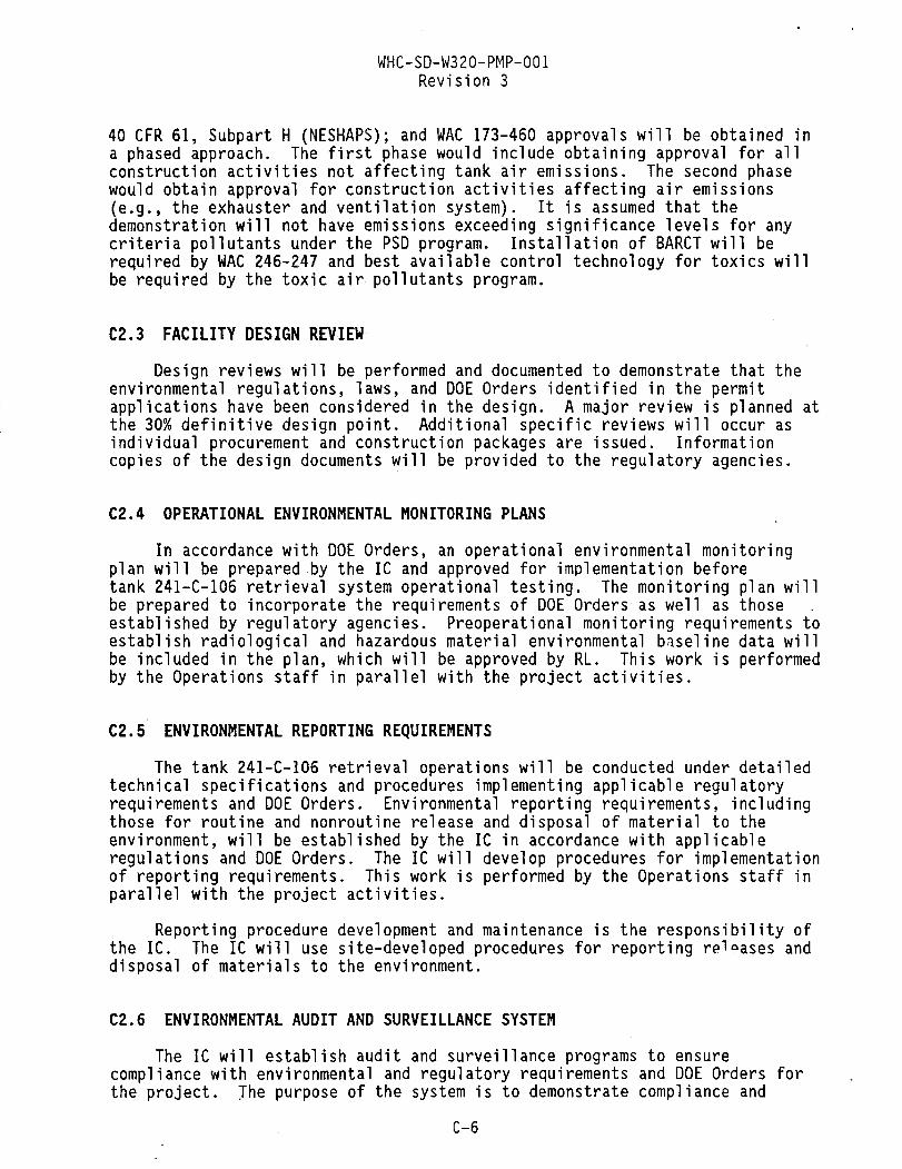
WHC-SD-W320-PMP-001 Revision 3
40 CFR 61, Subpart H (NESHAPS); and WAC 173-460 approvals will be obtained in a phased approach. The first phase would include obtaining approval for all construction activities not affecting tank air emissions. The second phase would obtain approval for construction activities affecting air emissions (e.g., the exhauster and ventilation system). It is assumed that the demonstration will not have emissions exceeding significance levels for any criteria pollutants under the PSD program. Installation of BARCT will be required by WAC 246-247 and best available control technology for toxics will be required by the toxic air pollutants program.
C2.3 FACILITY DESIGN REVIEW Design reviews will be performed and documented to demonstrate that the
environmental regulations, laws, and DOE Orders identified in the permit applications have been considered in the design. A major review is planned at the 30% definitive design point. Additional specific reviews will occur as individual procurement and construction packages are issued. Information copies of the design documents will be provided to the regulatory agencies.
C2.4 OPERATIONAL ENVIRONMENTAL MONITORING PLANS In accordance with DOE Orders, an operational environmental monitoring
plan will be prepared by the IC and approved for implementation before tank 241-C-106 retrieval system operational testing. The monitoring plan will be prepared to incorporate the requirements of DOE Orders as well as those established by regulatory agencies. Preoperational monitoring requirements to establish radiological and hazardous material environmental baseline data will be included in the plan, which will be approved by RL. This work is performed by the Operations staff in parallel with the project activities.
C2.5 ENVIRONMENTAL REPORTING REQUIREMENTS The tank 241-C-106 retrieval operations will be conducted under detailed
technical specifications and procedures implementing applicable regulatory requirements and DOE Orders. Environmental reporting requirements, including those for routine and nonroutine release and disposal of material to the environment, will be established by the IC in accordance with applicable regulations and DOE Orders. The IC will develop procedures for implementation of reporting requirements. This work is performed by the Operations staff in parallel with the project activities.
Reporting procedure development and maintenance is the responsibility of the IC. The IC will use site-developed procedures for reporting re^ases and disposal of materials to the environment.
C2.6 ENVIRONMENTAL AUDIT AND SURVEILLANCE SYSTEM The IC will establish audit and surveillance programs to ensure
compliance with environmental and regulatory requirements and DOE Orders for the project. The purpose of the system is to demonstrate compliance and
C-6

WHC-SD-W320-PMP-001 Revision 3
identify project areas that are not in compliance with environmental program criteria and standards. The IC and RL Program Support Division-Technical Support Branch (PSO-TSB) will be responsible for the performance of audits and surveillances. Audits and surveillances will be performed on a regular basis.
C2.7 ENVIRONMENTAL TRAINING PROGRAM The IC will establish the requirements for the selection, training, and
retraining of all individuals who operate, maintain, or supervise activities associated with startup and operations of the tank 241-C-106 retrieval system. The environmental training activities for the project will be as outlined in WHC manuals, DOE requirements documents, and environmental permits. The IC will maximize the use of existing training courses. The IC will augment the existing site training program with project-specific course material relative to system orientation, operations, and hazardous material handling. Project-specific training and qualification plans shall be prepared, implemented, and maintained by the IC to ensure that the project meets established design and functional requirements. Appendix I details the Project W-320 Startup and Operations Training Plan.
C3.0 SAFETY AND HEALTH
Safety and health requirements are an integral part of the project management plan. The DOE Orders mandate extensive safety reviews of the design. Specific subjects to be addressed are safety analysis reports, safety review and appraisals, reporting requirements, emergency planning, and training.
C3.1 SAFETY ANALYSIS DOCUMENTATION The safety documentation for Project W-320 will consist of the following.
C3.1.1 Unreviewed Safety Question (USQ) Evaluation To properly define the safety envelope for the waste retrieval of
tank 241-C-106, it is necessary to perform an USQ evaluation. Unless specifically exempted by the Plant Review Committee, the USQ review process will be applied to all Tank Waste Remediation System proposed changes and discoveries. The result of this USQ screening process will be to eliminate those items that clearly could not pose an USQ. The USQ evaluation will be prepared in accordance with WHC-IP-0842, Waste Tank Project Administration, Section 15.9 (Ellis 1994), and referred to the Plant Review Committee.
C3.1.2 Hazard Classification (HC) The facility HC will be determined based on the safety analyses performed
in accordance with established operating contractor procedures. The HC will
C-7

WHC-SD-W320-PMP-001 Revision 3
determine the appropriate review and authorization level of the Safety Assessment (SA) as well as provide a basis for applying a graded approach to the level of analysis and documentation of the SA. The HC will emphasize the importance of establishing quality in the safety analyses and will constitute the documents necessary for the quality assurance program plan. The HC will be prepared in accordance with WHC-CM-4-46, Nonreactor Facility Safety Analysis Manual.
C3.1.3 Preliminary Safety Evaluation (PSE) The PSE will be prepared in accordance with WHC-CM-4-46 to identify major
safety issues and to verify that the effects of these issues are minimized to the extent possible during the design phase. This PSE will address the following areas to the extent information is known at the stage of the design:
• Evaluation of compliance with current safety requirements and safety-related design criteria
• Preliminary analysis of the design's ability to adequately confine the radiological and other hazardous materials under normal and abnormal/accident condition(s)
• Risk to the parent facility arising from construction activities and equipment removal
• Proposed changes to the existing facility safety analysis.
C3.1.4 Preliminary Safety Equipment List (PSEL) The PSEL will identify the preliminary safety classification at the
system level of equipment that will be used for the waste retrieval of the contents of tank 241-C-106. The PSEL will emphasize the importance of establishing quality in the safety analyses and will identify components/ systems required for special consideration under a graded quality assurance program. These components are also identified in the project quality assurance program plan. The PSEL will be prepared in accordance with WHC-CM-4-46, Nonreactor Facility Safety Analysis Manual.
C3.1.5 Safety Equipment List (SEL) The SEL will identify the safety classification at the item (component)
level of equipment to be used for the waste retrieval of tank 241-C-106. The , SEL will be issued as a revision of the PSEL and included in the SA.
C3.1.6 SA An SA will be prepared for the project to identify hazards and assess
risks associated with retrieval operations and the means for their elimination and control. The safety assessment will address the requirements of DOE Order 5481.IB, Safety Analysis and Review System (DOE 1986).
C-8

WHC-SD-W320-PMP-001 Revision 3
The SA will serve as means of refining the safety envelope for the waste retrieval of tank 241-C-106. The SA will determine whether the sluicing of the material in tank 241-C-106 and transfer to tank 241-AY-1Q2 can be performed with an acceptable degree of risk. The SA will serve as a vehicle for ensuring that safety issues have been satisfactorily addressed in design and operating plans. The SA will have a limited duration of 1 year but can be reissued after it is reviewed to ensure adequacy. The SA will accomplish the following.
1. Describe (bound) the task. 2. Identify potential accidents and their initiators. 3. Evaluate consequences and probabilities (risk). 4. Establish controls.
The SA will identify the principal design criteria in sufficient detail to provide reasonable assurance that safe operation can be achieved; and will identify and demonstrate conformance to applicable guides, codes, and standards. If a deviation from current DOE design criteria occurs, it will be evaluated, approved, and documented by RL PSD-TSB. The SA will provide early identification of potential health, safety, or environmental problems and assess design features, administrative controls, and operational safety requirements necessary to prevent or mitigate potential accidents.
The SA will be prepared by the IC and approved by the DOE in accordance with WHC-CM-6-32, Safety Analysis and Regulation Work Procedures, Section WP-5.6. Compliance also shall be in accordance with WHC-CM-4-46, Section 3.0, "General Requirements," paragraph 4.4. The DOE has not specified a format for SAs in any DOE Orders. The DOE Office of Environmental Restoration and Waste Management (DOE-EM) has had a format fo:" an SA developed by Science Applications International Corporation. The DOE-EM has directed WHC to use this format for SAs submitted to them (Tseng 1993).
The SA will be revised to reflect design and safety analysis changes and will be maintained as a "living document."
The SA will be updated to describe and provide the safety assessment of the final facility designs. The SA will include or reference detailed operational safety requirements, and applicable codes, standards, and guides.
Figure C-l shows the relationship of safety documentation and various project stages.
C3.2 SAFETY REVIEWS AND APPRAISALS Independent safety reviews of the facility design, safety analyses, and
related documentation will be conducted to ensure compliance with safety and health protection standards and requirements. The E/C will review the design for safety and health impacts. Review of changes to technical baseline documents for safety impacts will be performed either as changes are made or on an annual basis by the E/C and IC.
C-9

USQ Screening PSE/PSEL I
HC
SEAC Input
o I
30% ;T rv
Design
A 1 Equipment Removal
A 1 Procurement
A Construction
Startup/ORR
y HC Hazard classification ORR = Operational readlnesa review PSE « Preliminary aatety evaluation PSEL m Preliminary Safety Equipment List SEAC » Safety and Environmental Advisory Council USQ = Unrevlewad safety question
Safety Assessment
SEAC

WHC-SD-W320-PMP-001 Revision 3
Audit, surveillance, and appraisal systems will be established to ensure compliance with safety and regulatory requirements and DOE Orders. The purpose of the systems will be to demonstrate compliance and identify project areas that are noncompliant with safety program criteria and standards. The IC will be responsible for the performance of audits, appraisals, and surveillances. Audits, appraisals, and surveillances will be performed on an "as-needed" basis during the construction phases, and as specified by WHC procedures during the operations phases of each project. The RL PSD-TSB will ensure that the project participants comply with safety criteria in accordance with DOE policy and with established standards and criteria.
C3.3 OCCURRENCE REPORTING REQUIREMENTS Notification, investigation, and reporting requirements for occurrences
related to safety controls and procedures will be specified in accordance with DOE Orders. Unusual occurrence reports will be prepared for events that adversely affect, or potentially affect, occupational or public health or facility safety, reliability, or performance. Additional details on roles and responsibilities during construction, startup, and operations are provided in Appendix D.
C3.4 EMERGENCY PLANS Emergency plans to handle potential accidents will be prepared in
accordance with DOE Orders. Plans will include emergency response and medical response to radiation incidents. The plans will be prepared by the IC and approved by RL and Ecology before startup. Additional details on roles and responsibilities during construction, startup, and operations are provided in Appendix D.
C3.5 TRAINING PROGRAM Programs will be established by the IC for the selection and training of
all individuals who operate, maintain, or supervise activities on the project. The project will maximize the use of existing training courses and use existing WHC training programs where appropriate. The project-specific training courses will be developed to augment the existing training program, if required. The specific training plans will address normal procedures, emergency actions, radiation and hazardous chemical control practices, location and functions of safety systems, operational or design change control procedures, and operational safety requirements. Additional details on startup and operational training are provided in Appendix I.
C3.6 CONSTRUCTION PLAN The Construction Plan defines overall responsibilities and outlines the
general scope of the Project W-320, Tank 241-C-106 Sluicing construction effort. Project W-320 will design, construct, and start up a system to retrieve and transfer the'contents from single-shell tank 241-C-106 to
C-ll

WHC-SD-W320-PMP-001 Revision 3
double-shell tank 241-AY-102. The project consists of design, procurement, equipment removal, construction, and startup. For more details, see Appendix K.
C4.0 REFERENCES
40 CFR 61, "National Emission Standards for Hazardous Air Pollutants," Code of Federal Regulations, as amended.
Clean Air Act of 1955, as amended, 42 USC 7401, et seq. DOE, 1986, Safety Analysis and Review System, DOE Order 5481.IB,
U.S. Department of Energy, Washington, D.C. DOE, 1987, Project Management System, DOE Order 4700.1, U.S. Department of
Energy, Washington, D.C. DOE, 1991, Nuclear Safety Policy, Secretary of Energy Notice 35-91,
U.S. Department of Energy, Washington, D.C. Ellis, S. H., 1994, Haste Tank Project Administration, WHC-IP-0842, Rev. 39,
Westinghouse Hanford Company, Richland, Washington. Harris, J. P., 1993, Permitting Plan for Project W-320, Tank 241-C-106 Waste
Retrieval Sluicing System (WRSS), WHC-SD-W320-EV-001, Rev. 0, Westinghouse Hanford Company, Richland, Washington.
National Environmental Policy Act of 1969, 42 USC 4321, et seq. Resource Conservation and Recovery Act of 1976, 42 USC 6901, et seq. Tseng, J., 1993, "Safety Documentation for Tank 241-C-106 Retrieval
Operations," U.S. Department of Energy, Washington, D.C. WAC 173-303, "Dangerous Waste Regulations," Washington Administrative Code, as
amended. WAC 173-460, "Controls for New Sources of Toxic Air Pollutants," Washington
Administrative Code, as amended. WAC 246-247, "Radiation Protection—Air Emissions," Washington Administrative
Code, as amended. WHC-CM-4-46, Nonreactor Facility Safety Analysis Manual, Westinghouse Hanford
Company, Richland, Washington. WHC-CM-6-32, Safety Analysis and Regulation Work Procedures, Westinghouse
Hanford Company, Richland, Washington.
C-12

WHC-SD-W320-PMP-001 Revision 3
C5.0 GLOSSARY
ABBREVIATIONS AND ACRONYMS ADM Action Description Memorandum BARCT best available radionuclide control technology CAA Clean Air Act of 1955 DOE U.S. Department of Energy DOE-EM U.S. Department of Energy-Office of Environmental Restoration and
Waste Management DOH U.S. Department of Health DST double-shell tank EA Environmental Assessment E/C Engineering/Construction Contractor Ecology Washington State Department of Ecology EPA U.S. Environmental Protection Agency ES&H Environmental, Safety, and Health FONSI finding of no significant impact HC hazard classification IC Integrating Contractor NEPA National Environmental Policy Act NOI Notice of Intent ORR operational readiness review PSD-TSB Program Support Division-Technical Support Branch PSE preliminary safety evaluation PSEL preliminary safety equipment list RCRA Resource Conservation and Recovery Act of 1976 RL U.S. Department of Energy, Richland Operations Office SEAC Safety and Environmental Advisory Council SEL safety equipment list SST single-shell tank USQ unreviewed safety question WRSS waste retrieval sluicing system
C-13

WHC-SD-W320-PMP-001 Revision 3
This page intent ional ly l e f t blank.
C-14

WHC-SD-W320-PMP-001 Revision 3
APPENDIX D
MEMORANDUM OF UNDERSTANDING BETWEEN THE MANAGER, SINGLE-SHELL TANK RETRIEVAL PROJECTS; THE MANAGER, EAST TANK FARMS OPERATIONS; AND
THE MANAGER, COMPLIANCE, SAMPLING, AND SUPPORT OPERATIONS FOR PROJECT W-320, TANK 241-C-106 SLUICING
D-l

WHC-SD-W320-PMP-001 Revision 3
CONTENTS
D1.0 PURPOSE D-3 D2.0 PROJECT DESCRIPTION D-3 D3.0 FUNCTIONS AND AGREEMENTS D-4
D3.1 MANAGEMENT . D-4 D4.0 REPORTS D-5 D5.0 PERSONNEL D-6 D6.0 FACILITIES D-7 D7.0 WORK CONTROL D-9 D8.0 INTERFACES D-ll D9.0 TRAINING D-12 DIO.O PROJECT ACTIVITIES OUTSIDE TANK 241-C-106 ISOLATED BOUNDARY . . . D-12 D11.0 REFERENCES D-13 D12.0 GLOSSARY . . . . . D-13
LIST OF FIGURES
D-1 Organizational Responsibilities . D-5 D-2 Facilities D-8
D-2

WHC-SD-W320-PMP-001 Revision 3
APPENDIX D
MEMORANDUM OF UNDERSTANDING BETWEEN THE MANAGER, SINGLE-SHELL TANK RETRIEVAL PROJECTS; THE MANAGER, EAST TANK FARMS OPERATIONS; AND
THE MANAGER, COMPLIANCE, SAMPLING, AND SUPPORT OPERATIONS FOR PROJECT W-320, TANK 241-C-106 SLUICING
D1.0 PURPOSE
This Memorandum of Understanding has been written to document the planned methods of accomplishing the sluicing of tank 241-C-106. Division of responsibilities and the interaction of the project organization with Operations organizations and other interfaces have been defined and agreed upon. This agreement should be considered a "living" document that will be reviewed annually, as a minimum, and reissued as required.
D2.0 PROJECT DESCRIPTION
Project W-320, Tank 241-C-106 Sluicing, will provide a sluicing system to achieve retrieval of the high-heat wastes from tank 241-C-106. The project is expense funded with an authorized $23 million budget for fiscal year 1994, and has been validated at $59.3 million total project cost. The project summary work breakdown structure is shown in Figure 5-2 of the Project Management Plan. The total project scope includes removal of existing failed equipment from the tank, and design, procurement, fabrication, construction, and startup of a sluicing system to mobilize and convey high-heat wastes from tank 241-C-106 to tank 241-AY-102. Project funds are provided through Activity Data Sheet (ADS) 1210-4. Retrieval operations funding will be used to prepare maintenance procedures (computer-based recall system [CBRS]) and operating procedures, train operations and support staff, and perform the actual sluicing operations. Retrieval operations funds also will be used for removal and processing of the tank 241-C-106 sluicing equipment following completion of the retrieval operations. This work is covered under ADS 1210-0-AJ.
The project organization consists of a multidisciplinary, intercontractor team. Disciplines involved include design, project, construction, and startup engineers. The construction team consists of management, supervision, and craft personnel. Matrixed support includes health physics, operations, and air-monitoring personnel. The Project W-320 organization is represented in Figure 3-3 of the Project Management Plan.
Tri-Party Agreement Milestone M-48, "Demonstration of SST retrieval technology," will be met by initiation of sluicing operations at tank 241-C-106. Secretary Hazel O'Leary's "Safety Initiative for Removal of C-106 High-Heat Waste" will be closed by completion of sluicing retrieval of 70% (minimum) of the strontium-loaded sludge from the tank.
D-3

WHC-SD-W320-PMP-001 Revision 3
The Project W-320 milestones are in accordance with the approved Project Authorization.
Project progress is reported to the U.S. Department of Energy through monthly management review meetings. The project team meets biweekly to discuss the status of the project.
D3.0 FUNCTIONS AND AGREEMENTS
The major functions to be performed and the related agreements required to perform tank 241-C-106 sluicing are discussed in the following sections. Principal organizations (parties) involved in this activity are (1) the project organization, referred to as the "project;" (2) the East Tank Farms Operations organization, referred to as "Operations;" and (3) the Compliance, Sampling, and Support Operations organization, referred to as "Operations Support."
D3.1 MANAGEMENT Overall responsibility for the successful execution and completion of
Project W-320 lies with the manager of Single-Shell Tank (SST) Retrieval Projects. The project organization is shown in Figure D-1. Construction and startup testing activities will be directed by the Retrieval Construction and Startup Manager. Actual construction work will be performed by ICF Kaiser Hanford Company (ICF KH), under the overall supervision of WHC project staff. Significant coordination will be required with the manager of Operations and the manager of Operations Support.
Project W-320 can be divided into several distinct time phases that see a shift of major responsibilities within the tank 241-C-106 geographic area. Significant in-farm work that began in March 1994 altered the security boundaries and introduced new buildings and infrastructure within the tank 241-C-106 immediate area. When intrusive work on the tank begins, additional measures of access security and control will be needed.
Responsibility for retrieval operations will ultimately rest with Operations. Single-Shell Tank Retrieval Projects is committed to providing startup, engineering, and construction support as required through retrieval operations.
Organizational transitions to support retrieval operations will be made as necessary. Design engineers will foil'".-? the project through construction and startup phases. Similarly, construction engineers, persons in charge (PIC), operators, and health physics technicians will remain assigned to support startup. These personnel will remain available, and be matrixed to Operations through retrieval completion. This philosophy will ensure that personnel familiar with the sluicing system are available to assist with any necessary repairs or replacements. This team will remain in place to facilitate timely removal of the sluicing system upon completion of sluicing
D-4

WHC-SD-W320-PMP-001 Revision 3
Figure D-l. Organizational Responsibilities.
Project W-320
Construction Management P I C s HPTs Startup
"1 Operations
ICF KH Start of Sluicing
Sluicing Complete
Subcontractors
Operations
PICs Startup
CM = Construction Manager HPT= Health physics technician PIC = Person in charge
HPTs Operations
Project W-320
C M
1 1
ICF KH
A4O303-O.CH3 04-26-»4
retrieval. This approach of shifting organizational responsibilities and personnel is shown in Figure D-l. A continuance of the philosophy will be carried over to Project W-340, Long-Reach Manipulator Retrieval System. Parts of the infrastructure, including the construction staging area, will remain intact through retrieval, sluicing system removal, and construction and startup testing for Project W-340.
D4.0 REPORTS
Routine daily logs and reports will be provided by the project to operations (at the location directed by Operations) through the site preparation, construction, and startup phases of the project. The Construction coordinator will ensure that daily log entries and reports provide information on work progress and lock and tag status, and that configuration information is current and accurate. The daily log will also provide operations information on activities planned for the following shift.
D-5

WHC-SD-W320-PMP-001 Revision 3
The manager of SST Retrieval Construction and Startup will make provision for any assistance required by Operations for Operations-generated reports. Notification of emergency, personnel injury, and potential reportable occurrences will be provided as required by WHC-IP-0263-TF, Tank Farm Building Emergency Plan (Ellis 1990) and WHC-IP-0842, Tank Farm Administration Manual, Section 5.6 (Ellis 1994).
Construction and Operations management will meet monthly. The primary purpose of these meetings will be to present a management overview of project status, and provide a forum for exchange of critical information, such as any change of requirements or policy that may affect the project or this agreement. Primary responsibility for maintenance of two-way communications lies with the managers of Operations and SST Retrieval Construction and Startup.
D5.0 PERSONNEL
Reporting to the Project W-320 Manager are Manager, Retrieval Construction and Startup; Manager, Retrieval Project Engineering; and Acting Manager, Retrieval Project Control and Administrative Support. Project W-320 has a cognizant Sluicing System Lead Project Engineer, Project Management Lead Engineer, Construction Coordinator, Lead Startup Manager, PICs, Technical Operations Support, TWRS Projects QA, ICF KH Design Manager, and ICF KH Construction Manager. This list represents the existing project team, and will be updated as necessary. Operations personnel and health physics technicians will be matrixed to the project team and integrated into all the activities required to complete the project.
Field work activities for Project W-320 will be performed by a dedicated project team. Other dedicated project personnel will include Westinghouse Hanford Company (WHC) management, planners, schedulers, and activity coordinators. Persons-in-charge will be WHC project employees specifically trained to perform the activities associated with this project. Westinghouse Hanford Company Safety and Quality Assurance staff members will be dedicated to Project W-320. An ICF KH Construction manager and superintendent will be assigned full time to the project team.
Project team members are expected to provide coverage from one phase of the project to another. Portions of the design team will continue to follow the project through construction. Similarly, construction personnel will continue from construction into startup. Project PICs, management, and engineering will be matrixed to Operations as required to complete the waste retrieval.
D-6

WHC-SD-W320-PMP-001 Revision 3
D6.0 FACILITIES
The C Farm Facility will require significant modifications that will essentially isolate tank 241-C-106 from the remainder of the C complex and to facilitate construction. These modifications are being performed to provide enhanced physical security and better access control and to structure radiological confinement.
The construction access area located north of tank 241-C-106 will be bounded by a secondary fence and will consist of the following:
• A combination change trailer Westinghouse radiological access monitoring (WRAM) station (with portal monitor)
• Several "connex"-type boxes for equipment/tool storage • A number of small field office trailers to support construction
engineering and supervision. A construction laydown area will be located on the west side of
tank 241-C-106 across the existing road from the farm. This area will be fenced and locked during off-shift hours.
The sluicing control trailer(s) will be located on the west side of the 241-AN Tank Farm, between Buffalo Avenue and the 241-AN berm. A small parking area will be graded and graveled immediately across the street from the farm. A "public" viewing stand will be erected on the west side of tank 241-C-106 so those not physically involved in retrieval construction or operations can view the area in a remote, upwind area.
Personnel access into and out of the tank 241-C-106 area normally will be routed through the change trailer. Authorized Operations personnel performing routine work may use a special access gate connecting the tank 241-C-106 area to the remainder of C Farm. Facility operations personnel will maintain control of access to tank 241-C-106 and the immediate vicinity to include the tank 241-C-106 heating, ventilating, and air conditioning skid.
Routine surveillance and maintenance will be provided as scheduled through the Plan of the Week. To provide consistency and allow coordination with minimal impact to the project schedule, the Production Control Scheduling organization is encouraged to schedule routine work the first week of each month. Project management will be notified of emergent work not carried on the Plan of the Week. The tank farm area immediately around tank 241-C-106 will be physically isolated from the rest of the farm by either a fence or forced-air structure (see Figure D-2). This area will be unlocked with the exception of the outer fence gates; the access gates within C Farm will be posted to prevent unauthorized entry. The outer fence gate accessing the change trailer will be equipped with a crashbar-type lock allowing entry to the trailer at all times while lockable to deny farm access from the trailer during off hours. The outer vehicle gate will be locked. Routine operations access normally will be through the unlocked inner gates; i.e., access through the existing C Farm change room and the general C Farm area.
D-7

WHC-SD-W32O-PMP-00I Revision 3
Figure 0-2. Facilities,
D-8

WHC-SD-W320-PMP-001 Revision 3
The project's manager of Construction and Startup, or designated representative, will conduct a daily facility inspection of the tank 241-C-106 area and document the results of this action. Particular emphasis will be placed on safety and good housekeeping. The Construction contractor(s) will be expected to maintain a clean, safe work environment.
D7.0 WORK CONTROL
The work control methodology to be used on this project has been defined in WHC-IP-0842, Tank Farm Administration Manual, Section 11.1, "Control of External Contractors" (Ellis 1994). The following information provides additional details on how work is to be accomplished within the project. Project W-320 will maintain representation at the Plan of the Week throughout the construction effort. Participation will be limited to coordinating Operations and Maintenance activities outside the project scope. Because a dedicated, matrixed support team will be in place, scheduling of resources to support the project should be restricted to exceptional cases when additional resources may be necessary; for example, additional Operations and Health Physics personnel may be required to provide stepoff pad support during pump removal and installation.
Monthly safety meetings will be held during the same period that the Tank Farms Operations and Maintenance organization normally conducts this activity. All safety meetings will be documented and become part of the project record.
Scheduling of work within the boundaries established around tank 241-C-106 will be performed through the manager of Construction and Startup. Project W-320 will be represented in the Plan of the Week and Plan of the Day, to provide concurrence with scheduled operations and maintenance activities within the bounded area. The project will also provide projections of the availability of matrixed health physics technicians and Operations personnel for work elsewhere during the following week.
Work package preparation will be performed by ICF KH Construction Engineering; job control will be maintained through the Process Control Package (PCP) normally used by ICF KH. Additional safety and environmental approvals, as determined by WHC impact level, will be obtained on the PCP. All appropriate permits will be included in the PCP. Examples of permits expected to be provided are excavation permits, core drill permits, cutting and welding permits, confined space permits, etc. In addition, this section of the PCP will include the Radiation Work Permit, Job Safety Analysis, and related safety documentation; these sections wil.l be clearly tabbed or otherwise marked for easy reference.
Procedures and work instructions will be provided in the PCP. These work instructions and procedures will be subjected to the same review and approval cycle as the bounding PCP. In most cases, this review and approval will be simultaneous. When a newly approved or amended procedure or instruction is included in the PCP, it will be identified on the PCP cover sheet with inclusion date noted.
D-9

WHC-SD-W320-PMP-00I Revision 3
Formal, routine pre- and post-job briefings, shift turnover meetings, PIC logs, Operations logs, and training will be used to ensure safe, efficient work performance. Additional briefings and/or meetings will be provided as needed.
Pre-job meetings will be held at the beginning of each shift and will involve all personnel required to support the day's activities. The pre-job meeting will include all activities planned for the shift, and will be documented daily. A sign-off sheet/checklist will be maintained in the project construction file through turnover of the sluicing system. Post-job meetings will be held upon completion of all work activities involving in-tank work, critical lifts, etc. Post-job as low as reasonably achievable briefs will only be conducted on long and complex jobs that can contribute to a "lesson learned."
The accelerated project schedule will, at times, require construction activities on more than one shift. Shifts will overlap by a minimum of one-half hour. Shift turnover will be accomplished through a combination of verbal turnover and review of the daily PIC log. Pre-job meetings will be held after the shift turnover is complete. The Operations log will be updated every shift. Daily work release will be authorized by the Operations Shift Manager based on review of the project operations log. Work release will be authorized via the daily release sheet, by job control system (JCS) work request number. Work release will be authorized via the daily log, by JCS work request number.
Document control will be maintained in accordance with WHC-CM-6-1, Standard Engineering Practices; WHC-CM-6-12, Projects Department Procedures; and all applicable ICF KH manuals and procedures.
Maintenance of the sluicing system, when startup testing and turnover is complete, will be the responsibility of the Tank Farms Maintenance organization. Vendor-supplied manuals and data will be provided to Production Control for initiation of any required periodic maintenance procedures (CBRS), upon receipt of equipment, to allow adequate time for procedure preparation. During the sluicing operation, SST Retrieval Engineering and Construction and Startup personnel will remain available as necessary to support system maintenance.
Operations and Maintenance personnel will continue to perform routine maintenance, surveillance, and miscellaneous operations evolutions on tank 241-C-106 throughout the construction and startup phases of the sluicing system. Scheduling of these activities needs to be performed as outlined previously. A noninclusive list of such operations and maintenance activities follows:
• Dry well monitoring • Level monitoring • Water additions • High-efficiency particulate air dioctyl phthalate • Lighting maintenance • Calibrations • Portal monitor (PCM-1B) maintenance.
D-10

WHC-SD-W320-PMP-001 Revision 3
Single-Shell Tank Retrieval Projects and ICF KH will remain responsible for control of all project activities from site preparation through startup, and for equipment removal when retrieval operations are done. Activities such as equipping and provisioning the change trailer will be performed by ICF KH, and will include stocking of anti-C clothing, breathing air masks, etc. The ICF Kaiser Hanford Company will maintain contamination control within the tank 241-C-106 fence; and will handle, package, and transport to storage/ disposal all wastes generated as a result of Project W-320 construction and startup.
D8.0 INTERFACES
Successful project communications with Operations, various programs, and other projects are crucial. Interfaces have been established with the Core Sampling, High Heat, and Vapor Issue Programs. These efforts will continue throughout the project. The High Heat and Vapor Issue Programs will be undertaking activities on tanks 241-C-103 and 241-C-106 throughout the Project W-320 construction period. Significant requirements exist for timely sampling of vapor space, liquid, and core material of tank 241-C-106. Results from these activities are needed to complete the design effort of Project W-320. The project will make every effort to clearly define those actions judged to be necessary and will recommend completion dates. Project personnel will assist and advise others; however, the achievement of results and the completion of analyses remain the responsibility of the Waste Characterization Program Office. The Project W-320 team is coordinating these efforts and will continue to do so through project completion.
Timely communication between the Project W-320 team and Operations is essential. In addition to maintaining Operations personnel as an integral part of the team, daily logs will be completed, by the project PICs and reviewed by Operations. This log will be kept at a location easily accessible, and as identified, by shift and facility Operations personnel.
The project will establish and maintain its own WRAM station within the security boundaries of the tank 241-C-106 area. Dedicated project health physics technicians and operators, matrixed to the project, will staff the station and provide constant coverage for all project work scheduled. The training criteria for entry into the tank 241-C-106 area will be identical to the remainder of the tank farms except for a requirement for additional facility orientation.
Procurement actions and responsibility will be divided between WHC and ICF KH. Design and construction-related procurement will be accomplished by ICF KH. All other procurement actions will be accomplished by the WHC project office.
Construction acceptance and operational startup testing will be conducted in accordance with approved project procedures. The Operations organization shall approve all operational test procedures. Testing of major equipment will include provision for operations "hands-on" test periods.
D-ll

WHC-SD-W320-PMP-001 Revision 3
Project W-340, Long-Reach Manipulator Retrieval System, is a follow-on project to W-320. The scope of Project W-340 is to retrieve the remaining waste from tank 241-C-106 and convey the waste to a double-shell tank receiver. Because Project W-340 is being managed by SST Retrieval Projects, this interface will be maintained in-house and coordinated with Project W-320.
D9.0 TRAINING
Training will be provided to Construction and Startup personnel as required for unescorted entry in the tank farm. A site-specific course will be developed for tank 241-C-106 facility and emergency response training. Particular emphasis will be placed on the physical hazards and hazardous materials likely to be encountered in the project environment. Course content will include enhanced information on the radiological conditions surrounding the tank 241-C-106 job site. Course generation and training will be complete before the tank 241-C-106 area is fenced off.
Additional activity-specific training will be provided to the team to support complex and high-risk activities. Dry-run training on mockups will be conducted after certification packages are developed by subject matter experts. The team of subject matter experts will consist of health physics technicians and representatives from Training, Operations, and Engineering organizations. Certification packages will form the basis of the training required for operators to become qualified to conduct tank 241-C-106 sluicing operations.
Currently, a Work Supervision Qualification Program is under development. The project PICs will be trained and certified in compliance with WHC-IP-0842 and the training program discussed earlier. All PICs will be certified before they begin actual field work.
D10.0 PROJECT ACTIVITIES OUTSIDE TANK 241-C-106 ISOLATED BOUNDARY
In addition to the work activities within the fenced area over tank 241-C-106, pipelines, electrical conduit, instrumentation lines, etc., will be installed between tanks 241-C-106 and 241-AY-102. The sluicer pump, a distributor drop leg, associated piping, electrical conduit, and instrumentation will be installed on tank 241-AY-102. This work, along with installation of the sluicing control t r ^ e r and transfer pipe between Buffalo Avenue and tank farm 241-AN, will be performed in the same manner as prescribed for tank 241-C-106. The exception will be scheduling integration—JCS packages will be initiated for major areas of work. These work requests will be used for scheduling purposes only. Work control and documentation will continue to be maintained via the PCP. The JCS work requests (J-2's) will be initiated for tracking purposes in accordance with WHC-IP-0842, Tank Farm Administration Manual, Section 11.1, "Control of External Contractors."
D-12
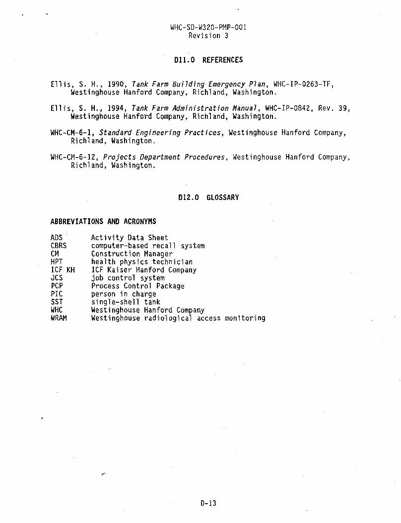
WHC-SD-W320-PMP-001 Revision 3
D11.0 REFERENCES
Ellis, S. H., 1990, Tank Farm Building Emergency Plan, WHC-IP-0263-TF, Westinghouse Hanford Company, Richland, Washington.
Ellis, S. H., 1994, Tank Farm Administration Manual, WHC-IP-0842, Rev. 39, Westinghouse Hanford Company, Richland, Washington.
WHC-CM-6-1, Standard Engineering Practices, Westinghouse Hanford Company, Richland, Washington.
WHC-CM-6-12, Projects Department Procedures, Westinghouse Hanford Company, Richland, Washington.
D12.0 GLOSSARY
ABBREVIATIONS AND ACRONYMS ADS Activity Data Sheet CBRS computer-based recall system CM Construction Manager HPT health physics technician ICF KH ICF Kaiser Hanford Company OCS job control system PCP Process Control Package PIC person in charge SST single-shell tank WHC Westinghouse Hanford Company WRAM Westinghouse radiological access monitoring
D-13

WHC-SD-W320-PMP-001 Revision 3
This page intentionally left blank.
D-14

WHC-SD-W320-PMP-001 Revision 3
APPENDIX E
PROJECT W-320 PROJECT MANAGEMENT PLAN, CONFIGURATION MANAGEMENT PLAN
E-l

WHC-S0-W3 20-PMP-OO1
Revision 3
CONTENTS
E1.0 INTRODUCTION E E2.0 ORGANIZATION E E3.0 TECHNICAL BASELINE IDENTIFICATION E
E3.1 FUNCTIONAL REQUIREMENTS BASELINE E E3.2 TECHNICAL REQUIREMENTS BASELINE E E3.3 DESIGN REQUIREMENTS BASELINE E E3.4 PRODUCT CONFIGURATION BASELINE E
E3.4.1 Design Documents E E3.4.2 Issuing Preliminary Documents E E3.4.3 Final Review and Approval E
E4.0 CONFIGURATION CHANGE CONTROL E E4.1 PROCEDURES E
E4.1.1 All Engineering/Design Configuration Changes . . . . E E4.1.2 Changes to Issued Documents—Revision 0, 1, etc. . . E E4.1.3 Changes to Documents Issued "Preliminary"—
Revision A, B, etc E E4.1.4 Records Management E E4.1.5 Development Control E E4.1.6 Process Control Packages E
E4.2 INTERFACE CONTROL E £4.2.1 Interface Between Project Systems and/or
Disciplines E E4.2.2 Interface to Cost and Schedule Control E E4.2.3 Interface with Other Projects Onsite E
E5.0 STATUS RECORDING AND REPORTING E E6.0 SPECIAL CONSIDERATIONS E E7.0 REFERENCES E
LIST OF FIGURES
E-l Configuration Control Process E
E-2

WHC-SD-W320-PMP-001 Revision 3
PROJECT W-320 PROJECT MANAGEMENT PLAN, CONFIGURATION MANAGEMENT PLAN
E1.0 INTRODUCTION
The purpose of this Configuration Management Plan is to define the processes employed for controlling the design, the design documents and records, and changes to the design for the duration of the project.
The format and content of this document have been developed based on DOE Order 4700.1, Project Management System, Chapter III, Attachment 111-5.
In accordance with DOE Order 4700.1, the objectives of Configuration Management are as follows.
1. Assist in achieving, at the lowest cost, the required system performance and operational efficiency.
2. Promote the maximum degree of design and development latitude, yet provide the appropriate degree and depth of configuration control.
3. Attain maximum efficiency in the management of configuration changes with respect to their necessity, benefit, cost, timing, and implementation.
4. Provide a systematic review of all changes to ensure that all primary and secondary effects of proposed changes are identified and their costs/benefits are weighed in making a decision to incorporate a change.
Most of these objectives are addressed in Westinghouse Hanford Company (WHC) and ICF Kaiser Hanford Company (ICF KH) issued procedures. The WHC procedures that implement configuration management requirements can be found in WHC-SD-WM-QAPP-018, Tank Waste Projects Quality Assurance Program Plan. The ICF KH procedures relating to Project W-320 configuration management actions are referenced in the appropriate sections of this Configuration Management Plan. Those not specifically addressed in the referenced project procedures are delineated in the following sections.
E2.0 ORGANIZATION
The project organization structure and responsibilities are detailed in Section 3.0 of the Project Management Plan.
E-3

WHC-SD-W320-PMP-001 Revision 3
E3.0 TECHNICAL BASELINE IDENTIFICATION
Section 6.2 of the Project Management Plan details the Baseline Management procedures and overall baseline control process.
E3.1 FUNCTIONAL REQUIREMENTS BASELINE The functional requirements baseline is presented in WHC-SD-W320-FDC-001,
Functional Design Criteria for Tank 241-C-106 Waste Retrieval, Project M-320.
E3.2 TECHNICAL REQUIREMENTS BASELINE The process for developing and maintaining the technical baseline is
detailed in the Engineering Process Manual, ENG 2.1, "Definitive Design Mobilization and Planning." All design inputs are documented and approved on the Technical Data Checklist, which is kept current for the duration of the job in accordance with ENG 2.1.
E3.3 DESIGN REQUIREMENTS BASELINE The Definitive Design Plan, W320DDP, details the design scope by
discipline and describes how the design is to be packaged and issued for construction. Process control descriptions (PCD) are being prepared for each subsystem that together make up the sluicing system. The PCDs describe how the requirements of the functional design criteria are met by the design.
E3.4 PRODUCT CONFIGURATION BASELINE
E3.4.1 Design Documents The following ICF KH procedures are used in the preparation and control
of definitive design documents including drawings, calculations, and specifications:
• ENG 2.1, "Definitive Design Mobilization and Planning" • ENG 2.2, "Design Document Preparation" • ENG 2.3, "Checking Design Documents" • ENG 2.4, "Review and Approval of Design Documents" • ENG 2.5, "Release of Design Documents."
E3.4.2 Issuing Preliminary Documents Before issuing a document for construction (Revision 0, 1, 2, etc.) a
document may be issued as "preliminary" (Revision A, B, C, etc.) to provide a static basis for cost re-estimation or in order to issue a current design configuration. The document will be prepared, reviewed, and approved in accordance with ENG 2.1, "Definitive Design Mobilization and Planning;"
E-4
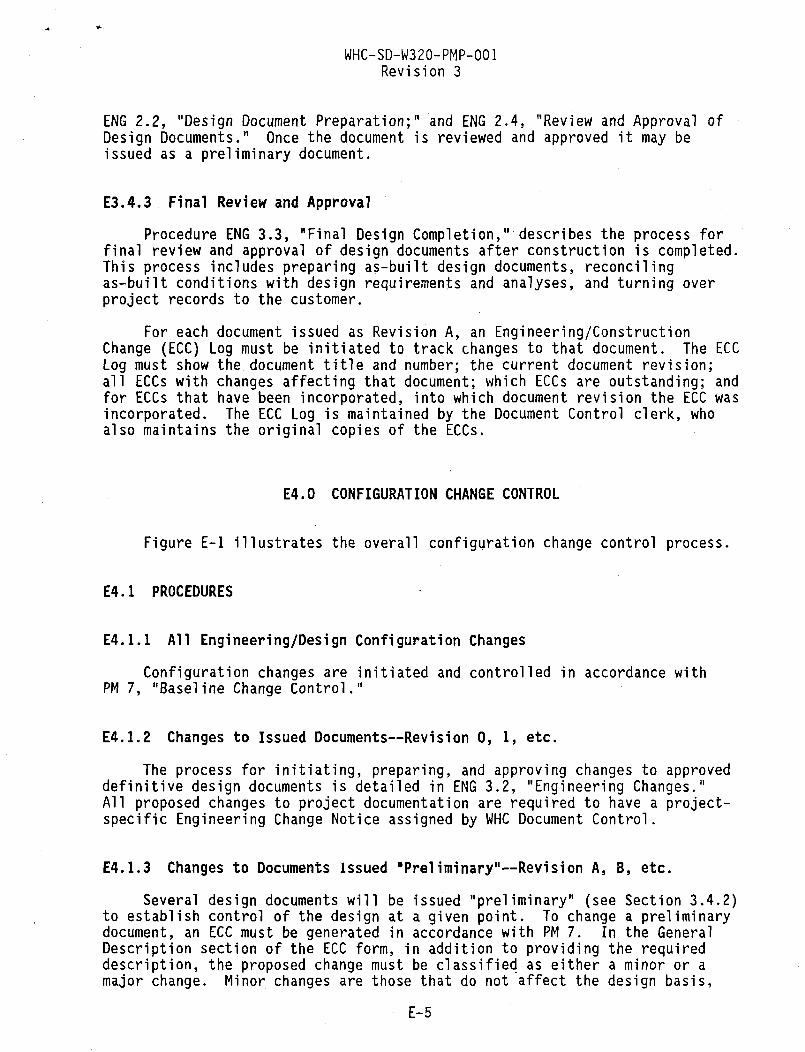
WHC-SD-W320-PMP-001 Revision 3
ENG 2.2, "Design Document Preparation;" and ENG 2.4, "Review and Approval of Design Documents." Once the document is reviewed and approved it may be issued as a preliminary document.
E3.4.3 Final Review and Approval Procedure ENG 3.3, "Final Design Completion," describes the process for
final review and approval of design documents after construction is completed. This process includes preparing as-built design documents, reconciling as-built conditions with design requirements and analyses, and turning over project records to the customer.
For each document issued as Revision A, an Engineering/Construction Change (ECC) Log must be initiated to track changes to that document. The ECC Log must show the document title and number; the current document revision; all ECCs with changes affecting that document; which ECCs are outstanding; and for ECCs that have been incorporated, into which document revision the ECC was incorporated. The ECC Log is maintained by the Document Control clerk, who also maintains the original copies of the ECCs.
E4.0 CONFIGURATION CHANGE CONTROL
Figure E-l illustrates the overall configuration change control process.
E4.1 PROCEDURES
E4.1.1 All Engineering/Design Configuration Changes Configuration changes are initiated and controlled in accordance with
PM 7, "Baseline Change Control."
E4.1.2 Changes to Issued Documents—Revision 0, 1, etc. The process for initiating, preparing, and approving changes to approved
definitive design documents is detailed in ENG 3.2, "Engineering Changes." All proposed changes to project documentation are required to have a project-specific Engineering Change Notice assigned by WHC Document Control.
E4.1.3 Changes to Documents Issued "Preliminary"—Revision A, B, etc. Several design documents will be issued "preliminary" (see Section 3.4.2)
to establish control of the design at a given point. To change a preliminary document, an ECC must be generated in accordance with PM 7. In the General Description section of the ECC form, in addition to providing the required description, the proposed change must be classified as either a minor or a major change. Minor changes are those that do not affect the design basis,
E-5

•CMP 3.1
Existing Dealgn
CMP 4.1.5 ir
Developmental Control
Fabrication Assembly Testing
Procurement
Acceptance Testing/Inspection
Functional Design Criteria Configuration
Management Flow
1 CMP 3.4.1
Definitive Design
if Dwg. Rev Control
CMP 3.4.2 (new Issue)
CMP 4.1.3 (change)
CMP 3.4.1
Release for Procurement
- , CMP 4.1.6
Release for Construction
i r CMP 4.1.6 4-
Construction
4i J "
Rework
Acceptable
Startup Testing
Yes
CMP 4.0
Design Configuration
Changes
No
CMP 4.1.2
Field Changes
Appendix E of Project W-320 Project Management Plan, Configuration Management Plan
H21SM.CH3 0S-12-S4

WHC-SD-W320-PMP-001 Revision 3
the code requirements, the project scope, or the quality requirements, and do not change engineered equipment. A marked-up (red-lined) version of the document clearly showing the proposed change must be attached to the ECC.
If the change is minor (e.g., administrative/typographical errors, labeling changes, etc.), the ECC is processed in accordance with PM 7, requiring the approval of the cost account manager and the project manager. Once the project manager has approved the change, it may be incorporated into the working copy of the design media, and therefore becomes the basis for further design or design changes. All applicable changes must be in compliance with PM 7.
If the change is major, the ECC must be approved by the project manager and reviewed and approved by the appropriate WHC technical personnel. Once approved by WHC, the change may be incorporated into the working copy of the design media in the same manner as a minor change.
Each document issued "preliminary" has an ECC Log that accompanies it (see Section 3.4). The ECC Log for the affected document must be updated to show that there is an outstanding revision to that document. The ECC Log shows which ECC contains the change information. The ECC Log and the original ECCs are maintained by the Project W-320 Document Control clerk.
If a change or if the accumulation of changes is of such a magnitude that a new revision of the "preliminary" document is justified, the project manager may authorize the incorporation of all outstanding changes into a new "preliminary" revision. The Log is then updated to show that the ECCs are no longer outstanding and into which revision of the document they were incorporated.
E4.1.4 Records Management The control, maintenance, and closeout of project documentation are
detailed in PM 8, "Project Documentation."
E4.1.5 Development Control An approved Project Deviation (Number PM 8.0D1) from the requirements of
PM 8 allows the use of preliminary drawings for fabrication of equipment removal system components by ICF KH (known as Development Control). Project W-320 Equipment Removal System Development Control Engineering Work Plan for ICF KH Designed Components, WHC-SD-W320-WP-003, describes the requirements for the Development Control process.
E4.1.6 Process Control Packages (PCP) Process control packages are initiated and controlled in accordance with
the Construction Process Manual, CON 1.2. The purpose of the procedure is to establish a method of preparing and implementing construction work packages. The packages are used to identify, control, and document construction activities requiring Performance Assurance and Quality Control inspections.
E-7

WHC-SD-W320-PMP-001 Revision 3
E4.2 INTERFACE CONTROL
E4.2.1 Interface Between Project Systems and/or Disciplines In accordance with ENG 3.2, the project lead engineer is responsible to
review all identified changes and coordinate the interfaces among all portions of the design/installation.
E4.2.2 Interface to Cost and Schedule Control Design changes are documented by ECCs. The ECC includes estimates of
cost and of schedule change. The project manager and the project lead engineer evaluate the ECC for technical, cost, and schedule impacts and approve or disapprove the ECC. Approved ECCs are forwarded to the Integrating Contractor for review.
Between the 30% and 90% design points, cost variances will be analyzed based on estimates to complete that are performed at a work package level and reported at the contractor work breakdown structure level. Cost trending will be reported monthly to identify potential changes to the 30% cost baseline.
A Change Request will be generated in accordance with PM 7 when the cost of an ECC or the sum of costs for current ECCs becomes >$50,000. The Change Request provides the interface between design changes and cost and schedule control.
E4.2.3 Interface with Other Projects 0nsite As Integrating Contractor, WHC has responsibility to identify other
projects onsite that may have an affect on, or be affected by, Project W-320.
E5.0 STATUS RECORDING AND REPORTING
The procedures for reporting project status, for management reporting, and for management reviews are contained in Section 6.5 of the Project Management Plan.
E6.0 SPECIAL CONSIDERATIONS
See Section E4.1.5, "Development Control."
E-8

WHC-SD-W320-PMP-001 Revision 3
E7.0 REFERENCES
Construction Process Manual, ICF Kaiser Hanford Company, Richland, Washington. Definitive Design Plan, W320DDP, Westinghouse Hanford Company, Richland,
Washington.
Engineering Process Manual, ICF Kaiser Hanford Company, Richland, Washington. Functional Design Criteria for Tank 241-C-106 Haste Retrieval, Project W-320,
WHC-SD-W320-FDC-001, Westinghouse Hanford Company, Richland, Washington. Project W-320 Equipment Removal System Development Control Engineering Work
Plan for ICF KH Designed Components, WHC-SD-W320-WP-003, Westinghouse Hanford Company, Richland, Washington.
Project Management System, DOE Order 4700.1, U.S. Department of Energy, Washington, D.C.
Tank Waste Projects Quality Assurance Program Plan, WHC-SD-WM-QAPP-018, Westinghouse Hanford Company, Richland, Washington.
E-9

WHC-SD-W320-PMP-001 Revision 3
This page intent ional ly l e f t blank.
E-10

WHC-SD-W320-PMP-001 Revision 3
APPENDIX F
PROJECT W-320 PROJECT MANAGEMENT PLAN, PROJECT-SPECIFIC WORK BREAKDOWN STRUCTURE DICTIONARIES
F-l

WHC-SD-W320-PMP-001 Revision 3
CONTENTS
F1.0 INTRODUCTION F2.0 SUMMARY LISTING F3.0 REFERENCES
LIST OF FIGURES
F-1 Dictionaries
LIST OF TABLES
F-1 Project-Specific Work Breakdown Structure Dictionary
F-2

WHC-SD-W320-PMP-001 Revision 3
APPENDIX F
PROJECT W-320 PROJECT MANAGEMENT PLAN, PROJECT-SPECIFIC WORK BREAKDOWN STRUCTURE DICTIONARIES
F1.0 INTRODUCTION
To understand the work content of every work breakdown structure (WBS) element, dictionary sheets are prepared. These dictionaries provide a description of each WBS element down through the cost account level. The purpose of the dictionary is to clarify the boundaries of each WBS element provided in Section 4.0 and determine the type of work that falls into that element. The dictionary is used as a guide by the activity manager in preparing the work scope description of the authorizing document. Table F-1 and Figure F-1 present the dictionary sheets for Project W-320.
F-3

WHC-SD-W320-PMP-001 Revision 3
F2.0 SUMMARY LISTING
Table F-1. Project-Specific Work Breakdown Structure Dictionary.
WBS index WBS WBS line number number level Task description
1 2 3
1.0 1.1 1.1.1
1 Project W-320 2 Project Management 3 Activity Management Reporting
4 5 5 7 8 9 10 11 12 13 14 15 16 17 18 19 20
1.2 1.2.1 1.2 ,2 .2 .2 .3 .3. .3. .3, .4 .4. .4. .4. .4. .4.
1.4.6
2 Engineering 3 Engineering Management 3 Technical Studies 3 Definitive Design 3 Engineering Inspection 3 Equipment Removal Design 2 CENRTC 3 CENRTC Definitive Design 3 CENRTC Procurement 3 CENRTC Fabrication 2 Construction 3 Construction Management 3 Inter-Farm Modifications 3 C Farm Modifications 3 AY Farm Modifications 3 Expense Procurement 3 Equipment Removal/Construction
21 22 23 24 25
26 27 28 29 30 31 32
1.5 1.5.1 1.5.2 1.5.3 1.5.4
1 1, 1. 1, 1. 1 1.6.6
2 Startup 3 Startup Administration 3 Startup Support 3 Startup Testing 3 Readiness Reviews
2 Safety and Environmental 3 Environmental Management 3 Safety Management 3 Safety 3 National Environmental Policy Act of 1969 3 Resource Conservation and Recovery Act of 3 Clean Air Act of 1955
1976
CENRTC = Capital equipment not related to construction WBS = Work breakdown structure
F-4

WHC-SD-W320-PMP-001 Revision 3
Figure F-l. Dictionaries, (sheet 1 of 9)
WORK BREAKDOWN STRUCTURE DICTIONARY WBS ELEMENT CODE: 1.1 TITLE: Project Management
PART II - ELEMENT DEFINITION CONTRACTOR: WHC
INDEX LINE NO.: 2-3 DATE: July 1994 REVISION NO. AND AUTHORIZATION: Revision 1
ELEMENT TASK DESCRIPTION COST CONTENT: Labor: Management Sources: Publishing
Staff Contracted consultants Secretarial support Computer support
Other Direct Costs: Travel and living Computer purchases Office supplies/furniture Training fees - classes, seminars, presentations,
and training materials Personnel moves (includes telephone and computer)
TECHNICAL CONTENT: Provide project integration and services as required to manage the project. Provide project management documentation as required to satisfy U.S. Department of Energy-Headquarters (DOE-HQ) and U.S. Department of Energy, Richland Operations Office (RL) Orders, including, but not limited to, DOE Order 4700.1, Project Management System (DOE 1987); DOE Order 6430.1A, General Design Criteria (DOE 1989); DOE Order 5700.6C, Quality Assurance (DOE 1991); WHC management directives and procedures; and compliance with state and local laws. WORK STATEMENT: Project management and administrative work performed to support the project, including, but not limited to: • Project management and integration • Business management • Qualification and training management • Preparation and support of validation and annual revalidation • Preparation and maintenance of project management plan • Preparation of project authorization and modification requests • Preparation and maintenance of quality assurance project plan • Project status reporting • Files turnover.
F-5

WHC-SD-W320-PMP-001 Revision 3
Figure F-l. Dictionaries, (sheet 2 of 9)
WORK BREAKDOWN STRUCTURE DICTIONARY WBS ELEMENT CODE: 1.2 TITLE: Engineering
PART II - ELEMENT DEFINITION CONTRACTOR: WHC
INDEX LINE NO.: 4-9 DATE: July 1994 REVISION NO. AND AUTHORIZATION: Revision 1
ELEMENT TASK DESCRIPTION COST CONTENT: Labor: Management Services: Reproduction
Secretarial support WHC assigned organization(s) ICF KH (all disciplines)
Other Direct Costs: Travel TECHNICAL CONTENT: Provide system and design engineering services for completion of definitive design, which will provide the design media to support procurement, construction, and startup. Also provide the field engineering services based on the approved definitive design media, i.e., construction drawings and construction specifications. Most of the work is performed at lower WBS levels and includes technical studies, conceptual design, preliminary design, detailed design, and field engineering inspection.
WORK STATEMENT: The Engineering activity encompasses all work efforts required to develop, verify, control, document, and approve the preliminary and detailed designs plus Field Engineering and Inspection activities in accordance with the functions and requirements and contract requirements. The work activities include, but are not limited to, the following: • IC and A-E engineering management • Maintenance of design criteria • Design reviews • Trade studies and Value Engineering stud'u-• Preparation, review, and approval of engineering change packages • Design of C Farm, AY Farm, and interfarm modifications • Preparation of estimates and schedules • Support of definitive design reviews • Development of procurement specifications • Preparation of inspection plans • Verification of contract/vendor submittals
F-6

WHC-SD-W320-PHP-001 Revision 3
Figure F-1. Dictionaries, (sheet 3 of 9)
Verification of workmanship Testing (i.e., soil compaction) Survey verification Engineering resolution of field issues A/I vendor inspections Identification and resolution of defects Acceptance of construction (A/I services) As-building of project drawings Turnover of project media and files.
F-7

WHC-SD-W320-PMP-001 Revision 3
Figure F-l. Dictionaries, (sheet 4 of 9)
WORK BREAKDOWN STRUCTURE DICTIONARY WBS ELEMENT CODE: 1.3 TITLE: CENRTC
PART II - ELEMENT DEFINITION CONTRACTOR: WHC
INDEX LINE NO.: 10-13 DATE: July 1994 REVISION NO. AND AUTHORIZATION: Revision 1
ELEMENT TASK DESCRIPTION COST CONTENT: Labor: ICF KH (all disciplines) Services: Procurement contracts
WHC assigned organization(s) Subcontracts TECHNICAL CONTENT: Procure capital equipment not related to construction (CENRTC) items and services to ensure vendor compliance with procurement specifications and to ensure CENRTC procurement activities are conducted in accordance with applicable DOE Orders and WHC A-E procedures. Fabricate and assemble CENRTC items into working systems as required by approved design. WORK STATEMENT: Perform those activities associated with the acquisition/fabrication of major equipment. Work performed for this WBS element supports the following activities:
• Procurement and fabrication of CENRTC items • Pre-bid advertising for major projects • Preparation of procurement bid packages • Issuance of documents and coordination of bidder site inspections • Evaluation of bids • Preparation of fair cost estimates as required • Award of contracts • Inspection and performance testing at vendor sites • Preparation of project management documentation.
CENRTC: • New control room • Equipment removal system equipment • Automated data processing equipment • Miscellaneous items at C Farm and AY Farm • Tank C-106 instrumentation upgrades.
F-8

WHC-SD-W320-PMP-001 Revision 3
Figure F-l. Dictionaries, (sheet 5 of 9)
WORK BREAKDOWN STRUCTURE DICTIONARY WBS ELEMENT CODE: 1.4 TITLE: Construction
PART II - ELEMENT DEFINITION CONTRACTOR: WHC
INDEX LINE NO.: 14-20 DATE: July 1994 REVISION NO. AND AUTHORIZATION: Revision 1
ELEMENT TASK DESCRIPTION COST CONTENT: Labor: Management Services: Procurement contracts
Secretarial support Subcontracts Clerical support ICF KH (all disciplines) WHC assigned organization(s)
Other Direct Costs: Travel and living TECHNICAL CONTENT: Perform construction functions in accordance with approved design media; applicable portions of DOE Orders; and WHC, A-E contractor, and subcontractor procedures. Ensure activities comply with applicable federal, state, and local regulations. WORK STATEMENT: The work elements encompassed by this WBS element include construction management, business management, procurement, contract and subcontract administration, configuration management, construction-related quality assurance and control, construction engineering, construction forces, construction/procurement subcontracts, health physics technician support, and "Persons-in-Charge" to direct the field activities. The work scope includes, but is not limited to, the following:
• Preparation and approval of construction plans, schedules, and work packages
• Training of field crews and supervision • Direction and oversite of field crews by "Persons-in-Charge" • Preparation of submittals • Advance procurement to expense-funded equipment and material • Bid and award of offsite construction contract • Fixed-price contract management • Mobilizing to onsite location • Trenching
F-9

WHC-SD-W320-PMP-001 Revision 3
Figure F-l. Dictionaries, (sheet 6 of 9)
Transfer pipe fabrication and installation Vent station fabrication and installation Electrical, instrument, and control system installation Hydrotesting Sitework and backfilling Identification and correction of uncompleted work (punch!isting) Work acceptance Contract closeout Projects records close-out.
F-10

WHC-SD-W320-PMP-001 Revision 3
Figure F-l. Dictionaries, (sheet 7 of 9)
WORK BREAKDOWN STRUCTURE DICTIONARY WBS ELEMENT CODE: 1.5 TITLE: Startup
PART II - ELEMENT DEFINITION CONTRACTOR: WHC
INDEX LINE NO.: 21-25 DATE: July 1994 REVISION NO. AND AUTHORIZATION: Revision 1
ELEMENT TASK DESCRIPTION COST CONTENT: Labor: Management Material: Test equipment and supplies
Secretarial support Test medium(s) WHC assigned organization(s) Startup engineers Services: Publishing Technician Equipment vendors
Calibration Other Direct Costs: Travel TECHNICAL CONTENT: Startup includes the work items following construction to complete a comprehensive startup readiness review, and to prepare for operations. Major items include preparing startup plans, procedures, and documentation; performing operational testing; and conducting readiness reviews. WORK STATEMENT: Determine the waste retrieval system operational interfaces; identify operator startup testing training requirements; develop startup test procedures and perform preoperational testing; and verify, demonstrate, and provide documentation required to ensure that the retrieval system meets operational design parameters. Specific items include, but are not limited to, the following:
• Startup management and integration • Development and implementation of startup plans and schedules • Development and implementation of startup administrative
manuals/procedures • Health physics, operations, and maintenance • Persons-in-Charge to direct all field work • Startup training • Preparation of operational test procedures (OTP) • Performance of OTP in the startup tests • -Readiness review meetings • Submitting readiness review to RL for approval
F-ll

WHC-SD-W320-PMP-001 Revision 3
Figure F-1. Dictionaries, (sheet 8 of 9)
• Review of existing facility documentation • Review and approval of document updates • Walk-down of construction work and generation of completion open items.
F-12

WHC-SD-W320-PMP-001 Revision 3
Figure F-l. Dictionaries, (sheet 9 of 9)
WORK BREAKDOWN STRUCTURE DICTIONARY WBS ELEMENT CODE: 1.6 TITLE: Safety and Environmental
PART II - ELEMENT DEFINITION CONTRACTOR: WHC
INDEX LINE NO.: 26-32 DATE: July 1994 REVISION NO. AND AUTHORIZATION: Revision 1
ELEMENT TASK DESCRIPTION COST CONTENT: Labor: Management Sources: Publishing
Staff Contracted consultants Secretarial Support Computer support
Other Direct Costs: Travel and living TECHNICAL CONTENT: Provide services, as required, to manage the preparation and submittal of environmental, safety, and structural analyses documentation to comply with DOE-HQ and RL Orders, WHC management directives and procedures, and state and local laws. WORK STATEMENT: Project management administrative work performed to support the project, including, but not limited to, the following: • Environmental documentation preparation • Safety documentation preparation and structural analysis preparation.
F-13

WHC-SD-W320-PMP-001 Revision 3
F3.0 REFERENCES
Clean Air Act of 1955, as amended, 42 USC 7401, et seq. DOE, 1987, Project Management System, DOE Order 4700.1, U.S. Department of
Energy, Washington, D.C. DOE, 1989, Genera7 Design Criteria, DOE Order 6430.1A, U.S. Department of
Energy, Washington, D.C. DOE, 1991, Quality Assurance, DOE Order 5700.6C, U.S. Department of Energy,
Washington, D.C. National Environmental Policy Act of 1969, 42 USC 4321, et seq. Resource Conservation and Recovery Act of 1976, 42 USC 6901, et seq.
F-14

WHC-SD-W320-PMP-001 Revision 3
APPENDIX G
PERKITTING PLAN FOR PROJECT M-320, TANK 241-C-106 WASTE RETRIEVAL SLUICING SYSTEM*
G-l

WHC-SD-W320-PMP-001 Revision 3
This page intent ional ly l e f t blank.
6-2

Westinghouse Hanford Company
WHC-SD-W320-PMP-001 Revision 3
Internal Memo
From: Regulatory Program Integration Phone: 372-2234 Date: November 23, 1993 Subject: PROJECT W-320, TANK 241-C-106 SLUICING PERMITTING PLAN
8811Q-KST-93-U7
To: J . P. Harr is I I I S4-55
cc: A. T. Alstad Rl-49 P. J. Mackey J. W. Bailey S4-55 L. B. McOaniel D. E. 8owers S6-Q1 S. M. Price R. C. Bowman
H 6 - 3 Q ^ \> W. J. Rued
W. R. Brown H 6 - 3 Q ^ — 0. J. Shrimpton M. A. Cahill S 4 - 5 7 * ^ M. A. Siano 0. J. Carrel 1 H6-22 C. E. Sowa M. W. Cline H6-24 K. G. Squires R. W. Davidson E6-21 G. A. Symoris R. H. Engelmann H6-26 EPIC J. M. Henderson S4-55 KST:F il'e/LB J. J. Luke H6-25
83-15 S4-55 H6-23 H6-26 E6-21 G6-02 H6-25 S4-55 S4-55 H6-08 H6-30
Attached is the Project W-320, Tank 24I-C-106 Sluicing Permitting Plan. This permitting plan was based on information contained in the Functional Design Criteria, and a Letter Report prepared by KEH, dated February 1993. The Work Plan prepared by WHC, to provide permitting support for the project, was also utilized as a reference. It should be noted that the regulations of concern are subject to change prior to the time that actual permit applications are submitted. Additionally, if the scope of activities is modified from that stated in the permitting plan, re-evaluation of the permitting requirements will be necessary.
Should you have further questions or comments, please call me on 372-2234.
<-, - '. ---~t . J-K. S. Tollefson Senior Scientist
jcu Attachment
Hanford Operation* and Engineering Contractor for th« US Oepartmant of Enargy
G-3

WHC-SD-W320-PMP-001 Revision 3
WHC-SD-W320-EV-001 REV 0
PERMITTING PLAN FOR
PROJECT W-320 TANK 24I-C-106 WASTE RETRIEVAL SLUICING SYSTEM (WRS5)
PERMITTING PLAN TEAM MEMBERS
PROGRAM INTEGRATION A.J': •_ ... / ' .
NEPA AND SEPA K. S./Tollefson
/ /
AIR PERMITTING W.-J. Rued
RCRA PERMITTING C. E. Sowa
' M. M. Cline
PROJECT ENGINEER
TANK WASTE PROJECTS n^/*<d£&Z--
G-4

WHOSD-W320-PMP-001 Revision 3
WHC-SD-W320-EV-001 REV 0
(This page l e f t in tent iona l ly blank.)
11
G-5
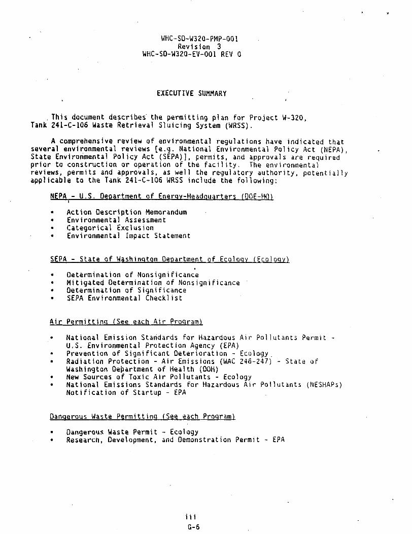
WHC-SO-W32Q-PMP-001 Revision 3
WHC-SD-W32Q-EV-Q01 REV 0
EXECUTIVE SUMMARY
. This document describes the permitting plan for Project W-320, Tank 241-C-106 Waste Retrieval Sluicing System (WRSS).
A comprehensive review of environmental regulations have indicated that several environmental reviews [e.g. National Environmental Policy Act (NEPA), State Environmental Policy Act (SEPA)], permits, and approvals are required prior to construction or operation of the facility. The environmental reviews, permits and approvals, as well the regulatory authority, potentially applicable to the Tank 241-C-106 WRSS include the following:
NEPA - U.S. department of Energy-Headouarters (OOE-Hm
• Action Description Memorandum • Environmental Assessment • Categorical Exclusion • Environmental Impact Statement
SEPA - State of Washington department of Ecology (Ecology) •
• Determination of Nonsignificance • Mitigated Determination of Nonsignificance • Determination of Significance • SEPA Environmental Checklist
Air Permitting (See each Air Program)
• National Emission Standards for Hazardous Air Pollutants Permit -U.S. Environmental Protection Agency (EPA)
• Prevention of Significant Deterioration - Ecology. • Radiation Protection - Air Emissions (WAC 246-247) - State of
Washington Department of Health (DOH) • New Sources of Toxic Air Pollutants - Ecology • National Emissions Standards for Hazardous Air Pollutants (NESHAPs)
Notification of Startup - EPA
Dangerous Waste Permitting (See each Program)
• Dangerous Waste Permit - Ecology • Research, Development, and Demonstration Permit - EPA
m G-6

WHC-SD-W320-PMP-001 Revision 3
WHC-SD-W320-EV-001 REV 0
Miscellaneous Reviews/Permits/Approvals
• Preoperation Monitoring of Facilities, Sites and Operations -U.S. Department of Energy, Richland Field Office (RL) Floodplain/Wetlands Assessment - RL Cultural Resource Review Clearance - RL Excavation Permit - RL Endangered Species Approval - RL Larger Qnsite Sewage System Permit - OOH
This document describes the environmental reviews (e.g. NEPA, SEPA), permits and approval requirements for the project. It provides a summary of permit application data requirements, alternative strategies for permit completion and approval as well as the estimated probability of success for each alternative strategy.
iv G-7

WHC-SO-W320-PMP-G01 Revision 3
WHC-SD-W320-EV-001 REV 0
CONTENTS
i.O INTRODUCTION 1 2.0 NATIONAL ENVIRONMENTAL POLICY ACT 3
2.1 INTRODUCTION 3 2.2 SUMMARY OF DATA/INFORMATION REQUIREMENTS FOR THE TANK 241-C-106 WRSS 2 2.3 OISCUSSIQNOF ALTERNATIVES* FOR'THE* TANK 24i-C-io6 WRSS '.'.'.'. 4 2.4 SCHEDULE PERMITTING STRATEGY 4
3.0 STATE ENVIRONMENTAL POLICY ACT 5 3.1 INTRODUCTION 5 3.2 ' SUMMARY OF DATA/INFORMATION REQUIREMENTS FOR THE TANK 241-C-106 * WRSS 6
3.3 0ISCUSS10N0F ALTERNATIVES FOR THE TANK 241-C-io6 WRSS '.'.'.'. 5 3.4 SCHEDULE PERMITTING STRATEGY ... 6
4.0 RESOURCE CONSERVATION ANO RECOVERY ACT 7 4.1 INTRODUCTION 7 4.2 SUMMARY OF DATA/INFORMATION REQUIREMENTS FOR THE TANK 241-C-106
WRSS 9 4.3 DISCUSSION OF ALTERNATIVES FOR THE TANK 241-C-106 WRSS . . . . 9 4.4 SCHEDULE PERMITTING STRATEGY 10
5.0 THE CLEAN AIR ACT ' 11 5.1 INTRODUCTION 11 5.2 SUMMARY OF DATA/INFORMATION REQUIREMENTS FOR NESHAP AND
WAC 246-247 PERMIT APPLICATIONS ANO NOTICE OF CONSTRUCTION . . 13 5.3 DISCUSSION OF ALTERNATIVES FOR THE TANK 241-C-106 WRSS . . . . 13 5.4 SCHEDULE PERMITTING STRATEGY 13
6.0 MISCELLANEOUS ASSESSMENTS, PERMITS, AND APPROVALS 15 6.1 CULTURAL RESOURCE REVIEW 15 6.2 EXCAVATION PERMIT 15 6.3 ENOANGERED SPECIES ACT COMPLIANCE 15 6.4 PREOPERATION MONITORING OF FACILITIES, SITES, AND OPERATIONS . 15 6.5 LARGER ONSITE SEWAGE SYSTEM PERMIT 15
GLOSSARY 17 FIGURE - PROJECT W-320 PERMITTING SCHEDULE 19 FIGURE - PROJECT W-320 PERMITTING SCHEDULE ' . . . . 21 FIGURE - PROJECT W-320 PERMITTING SCHEDULE . 23 FIGURE - PROJECT W-320 PERMITTING SCHEDULE . . . . 25 APPENDIX 27
v G-8

WHC-SD-W320-PMP-001 Revision 3
WHC-SD-W320-EV-001 REV 0
(This page left intentionally blank.)
VI G-9

WHC-SD-W320-PMP-001 Revision 3
WHC-SD-W320-EV-OO1 REV 0
PERMITTING PLAN FOR
PROJECT W-320 TANK 241-C-106 WASTE RETRIEVAL SLUICING SYSTEM (WRSS)
1.0 INTRODUCTION
This document describes permitting requirements for design, construction and demonstration of waste retrieval technology from single-shell tanks. Milestone M-07-00, established in the Hanford Federal Facility Agreement and Consent Order, otherwise known as the Tri-Party Agreement, requires waste retrieval from Hanford Site Single-Shell Tanks (SSTs) as the initial phase of SST closure. Tank 241-C-1Q6 has been identified as the M-07-00 retrieval demonstration tank. For purposes of this document, decontamination is defined as a reduction in radioactive contamination to minimize occupational exposure.
In support of waste retrieval, it is necessary to remove existing equipment and install new equipment in Tanks 241-C-106 and 241-AY-102. The levels of contamination in the pits and on the equipment are extremely high resulting in unacceptable personnel exposure rates. Therefore, it is mandatory to reduce the radiation exposure, as much as possible, to allow for personnel access to remove and install equipment. Carbon dioxide (C02) decontamination and/or a standard water/stream jetting system will be utilized for both decontamination of the C-106 pump, heel and sluice pits, and for decontamination of the pumps as they are extracted from the tanks into the receivers. The pumps will then be inserted into a container for transportation to interim storage.
Project W-320 is intended for mobilization and removal of the heat-generating sludge in Tank 241-C-106 to resolve the high-heat safety issue. Tank-to-tank sluicing, an existing technology, will provide the earliest possible closure of this safety issue. Removal of the heat-generating sludge will allow cooling water additions to cease. The cessation of cooling water additions will allow operations to place Tank 241-C-1Q6 in a safe, interim stabilized state. Additional retrieval operations can proceed using alternate technology, as required, to achieve 95% waste retrieval according to the terms of the Tri-Party Agreement Milestone M-07-QQ. Waste from Tank 24L-C-106 has been identified as an early feed to the Hanford Waste Vitrification Plant (HWVP) because the material requires only simple sludge washing pretreatment prior to vitrification. This retrieval action is required to maintain HWVP operations continuity following initial Double-Shell Tank (DST) waste from neutralized current acid waste from Tanks 241-AZ-101 and 241-AZ-1Q2.
The Tank 241-C-106 WRSS will be designed to remove the radioactive and chemical sludge from Tank 241-C-106, and transport that material to the 241-AY-102 DST via a new, temporary, above grade, shielded, encased transfer line. The system will include hardware specific to retrieval of waste tank contents, all supporting structures, facilities (including control room, lunchroom, and sanitary facilities), waste tank modifications, receiver tank system modifications necessary to retrieve Tank 241-C-106, the transfer line to and from the DST system, and all
I G-10

WHC-SD-W320-PMP-001 Revision 3
WHC-SD-W320-EV-001 REV 0
associated support equipment. All Tank 241-C-106 process components and supporting equipment shall have a design life of two years including twelve months for retrieval operations.
This permitting plan has been prepared based on the Tank 241-C-106 Functional Design Criteria, the Work Plan to provide permitting support for Tank 241-C-106 Waste Retrieval, and the added scope of the C0 2 decontamination demonstration.
2 G-ll

WHC-SD-W32G-PMP-001 Revision 3
WHC-SD-W320-EV-0G1 REV 0
2.0 NATIONAL ENVIRONMENTAL POLICY ACT t
The NEPA 42 U.S.C. 4321 et seq, was enacted to ensure that environmental matters are considered prior to initiation of federal actions which may affect the quality of the human environment. The OOE regulations (10 Code of Federal Regulations [CFR] 1021) promulgated under NEPA were developed to assess the environmental impacts associated with specific DOE proposals or actions.
2.1 INTRODUCTION
If a proposed action appears to be covered under an existing approved environmental impact statement (EIS) or environmental assessment (EA), the relevant Record of Decision or finding of No Significant Impact (FONSI) should be examined to ensure the proposed action is adequately bounded by existing documentation.
In the event that RL determines that a proposed action is not covered by existing environmental documentation, an evaluation would be required to determine whether the proposed action falls within one of the categorical exclusions (CX). If the proposed action is covered by a CX, then an information bulletin (IB) is prepared that summarizes the proposed action and its background. In addition, an explanation of how the action meets the minimum requirements of a CX is needed.
If the proposed action is not covered by a CX, then an action description memorandum (AOM) is developed. The AOM provides a brief but concise description of the proposed action, the potentially affected environment, anu possible environmental impacts. All AOMs are sent to RL, and may be subsequently transmitted to DOE-HQ to determine if the proposed action warrants an EA or an EIS.
The EA is developed to discuss the environmental consequences of the proposed action and the alternatives to that action, including: the consequences of accidents and routine operations, and the cumulative and long term impacts. A discussion of the relationship, of the proposed action to federal, state, and local land use plans, policies, and regulations is also discussed in the EA. EAs are submitted to RL for review and are then transmitted to DOE-HQ for final determination made by the Assistant Secretary for Environment, Safety and Health. This determination will result in a decision that the proposed action is a major action significantly affecting the environment, requiring an EIS, or issuance of a FONSI.
2.2 SUMMARY OF DATA/INFORMATION REQUIREMENTS FOrt THE TANK 241-C-1Q6 WRSS
See Appendix, Section 1.0 for a summary of the minimum data/information needs required for development of the NEPA documentation for the Tank 241-C-106 WRSS.
3 G-12

WHC-SD-W320-PMP-001 Revision 3
WHC-SD-W320-EV-001 REV 0
2.3 DISCUSSION OF ALTERNATIVES FOR THE TANK 241-C-106 WRSS
Various NEPA compliance alternatives may be available in an effort to support the Tank 241-C-106 WRSS. The probability of success (high, medium, low) will follow each listed alternative. See Figure for the W-320 permitting schedule.
1. To determine the most appropriate type of NEPA coverage, an ADM can be prepared. This would likely result in a determination that an EA is required. The desired outcome of the EA would be a FONSI, after which the project could proceed. The scope of work covered included under the CO, blasting will be covered by the routine
' maintenance CX. (High)
. 2. Same as alternative one but the outcome of the EA is a requirement to prepare an EIS. (Low)
3. Alternative three is the possibility of NEPA coverage of the Tank 241-C-106 WRSS under the Hanford Defense Waste EIS- This alternative has been explored and guidance was provided from OOE-HQ to prepare an AOM/EA- (Low) »
2.4 SCHEDULE PERMITTING STRATEGY
For design, construction, and demonstration of the Tank 241-C-106 './RSS. an AOM/EA will be prepared. The assumed outcome of this ADM/EA is a FONSI.
4 G-13

WHC-SD-W320-PHP-001 Revision 3
WHC-SD-W320-EV-001 REV 0
3.0 STATE ENVIRONMENTAL POLICY ACT
The SEPA, Chapter 43.21C Revised Code of Washington legislation which requires evaluation of environmental impacts associated with a project or an agency action prior to approval. The SEPA Rules, Chapter 197-11 Washington. Administrative Code (MAC), are the implementing regulations.
3.1 INTRODUCTION
One agency is identified as lead agency for each project. The lead agency is responsible for assuring that SEPA compliance is completed prior to approving the proposed project. SEPA compliance is required for any project or proposal which meets the definitions of "action" in the SEPA Rules. See WAC 197-11-704. This includes projects which require a permit (e.g., Hazardous Waste Permit, Building Permit) or other approval from a governmental agency prior to operation. At the Hanford Site, Ecology is the lead agency for projects ("Actions") involving permitting of hazardous waste treatment. storage, or disposal facilities.
The SEPA compliance for a given project is completed prior to the lead agency making a decision to approve the project. At the Hanford Site, a SEPA environmental checklist is prepared prior to submittal of the first permit application to Ecology. The SEPA environmental checklist must accompany the permit application. The permit/approval may be conditioned or denied based on information in the SEPA environmental checklist. SEPA compliance ii required, in addition to the normal permits or approvals, for a project.
When SEPA compliance is required for a project, the responsible official of the lead agency must make a threshold determination by deciding if a project is likely to have probable •significant adverse impacts on the environment. [f a project may have significant adverse impacts, a Determination of Significance (OS) will be issued and a State Environmental Impact Statement (SEIS) may be required. If the project will not have significant adverse impacts, or if the impacts can be mitigated, a determination of nonsignificance (ONS) or mitigated ONS will be issued. The threshold determination is normally based on the environmental checklist completed for the project and any information which the lead agency has on file.
The SEPA allows the lead agency to adopt a MEPA EA or EIS in lieu of doing additional review under SEPA (WAC 197-11-610). See Figure -Project W-320 Permitting Schedule, pages 19-27 for the Project W-320 permitting schedule.
5 G-14

WHC-SO-W320-PMP-D01 Revision 3
WHC-S0-W320-EV-001 REV 0
3.2 SUMMARY OF DATA/INFORMATION REQUIREMENTS FOR THE TANK 241-C-106 WRSS
See Appendix, Section 2-0 for a summary of the minimum data/information needs required for development of the SEPA documentation for the Tank 241-C-106 WRSS.
3.3 DISCUSSION OF ALTERNATIVES FOR THE TANK 241-C-106 WRSS
Various SEPA avenues may be evaluated in an effort to support the Tank 241-C-106 WRSS. The alternatives open for consideration are discussed below. The probability of success (high, medium, low) will follow each listed alternative.
1. A ONS from the State for the Tank 241-C-106 WRSS. (High)
2. OS by the State. Subsequent Adoption of NEPA documentation by the State for the Tank 241-C-1Q6 WRSS. (Medium)
3. A mitigated DNS from the State. (Low)
4. OS from the State and requirement to prepare separate State £[S. (Low)
3.4 SCHEDULE PERMITTING STRATEGY
A SEPA environmental checklist must be prepared for the Tank 241-C-106 WRSS. This checklist should accompany the Notice of Intent (HOI) v/hich is the first step in .the Resource Conservation and Recovery Act (RCRA) Permitting process. The state may issue a ONS for the Tank 241-C-106 URSS and adopt the NEPA documentation.
G-15

WHC-SO-W320-PMP-001 Revision 3
WHC-SD-W320-EV-001 REV 0
4.0 RESOURCE CONSERVATION AND RECOVERY ACT
The RCRA, 42 U.S.C. 6901 et seq. was enacted as a comprehensive national program to mandate that hazardous waste will be'treated, stored and disposed of so as to minimize the present and future threat to human health and the environment. In the State of Washington, the Dangerous Waste Regulations, WAC 173-303, are the implementing regulations.
4.1 INTRODUCTION
The Dangerous Waste Regulations apply to all facilities within Washington State that treat, store and/or dispose (TSO) of dangerous waste. These regulations are equivalent to, or more stringent than, the federal hazardous waste regulations. Under the dangerous waste program all TSO facilities must obtain a permit. Facilities which were in existence on November 19, 1980, were granted an Interim Status permit with the submittal of a Part A permit application identifying their intent to TSO of dangerous waste. Interim Status ends after final administrative disposition of a Part B permit application is completed and either a Final Status permit is denied or granted. All new construction requires that a Final Status permit be granted before initiating construction, defined by Ecology as ground breaking.
» Expansion of an existing Interim Status facility, comprising of less than
50% of the existing capital investment, can proceed under Interim Status. Expansion to an existing Interim Status facility, comprising of 50';;. or more of the existing capital investment, requires a Final Status permit before initiating construction. Once a facility has been granted a Final Status permit, expansion or modification to that facility requires a modification to the Final Status permit in accordance with WAC 173-303-330. Pilot Planes used to provide research or demonstrate treatment technologies could reouira a Research, Development, and Demonstration (RD&D) permit in accordance with 40 CFR 270. The R0&0 permit is administered by EPA and must be obtained before initiating construction.
An application for a dangerous waste management permit consists of three collective submittals. Each submittal consists of various levels of detailed information concerning the facility. The three submittals are the NO I, the Part A permit application (Part A ) , and the Part B permit application (Part 8 ) . See Figure - Project W-32Q Permitting Schedule, pages 19-27 for the Project W-320 permitting schedule.
Notice of Intent The NOI identifies an applicant's intent to construct and operate a ISO
facility in accordance with WAC 173-303-281. In addition, an NOI can identify the expansion of an existing TSD facility. The NOI contains preliminary information concerning the proposed facility and/or expansion. The NOI requires a general process description, operating capacities, waste type. development and submittal of a SEPA Checklist, a topographic map, and a statement of environmental conditions.
7 G-16

WHC-SO-W32O-PMP-0O1 Revision 3
WHC-SD-W320-EV-001 REV 0
In accordance withWAC 173-303-281, the NOI must be submitted to the Ecology and the public reading rooms, and a public notification published in a local daily newspaper, at least 150 days prior to submittal of the Part A permit application. The NOI process normally requires approximately 11 months to complete, which at the completion of the Public Review period, the Part A permit application is submitted.
Part A
The Part A consists of completing the Dangerous Waste Part A permit application, Farms 1 and 3. The Part A can be submitted no earlier than 150 days after the NOI is published. The Part A can be submitted concurrently with the Part 8; however, in most instances the PartA is filed in advance of the Part 8. The Part A preparation process (following the submittal of the .NOI) requires approximately 5 months to complete, including the WHC/RL review and certification requirements.
Part B
The Part 8 consists of detailed design, technical, operational. maintenance, engineering, training, closure, and other relevant information concerning the waste management facility,, in accordance with the Part 8 checklist provided by Ecology. The information is presented in a narrative format, often utilizing extensive figures, tables, and design media.
The Part 8 is evaluated by the agencies for completeness and technical adequacy. The latter includes plausibility, general detail of plans and procedures, and protection of the environment. For any item deemed incomplete or technically inadequate, Ecology issues a Notice of Deficiency (MOD) to the applicant. The applicant responds to the NOD and if accepted by Ecology. modifications are made to the Part 8 as necessary. The "NOO/response Part 3 revision" iterative phase takes a minimum of 360 days and often lunger depending on the agency's manpower resources, acceptance of the application concept, or if regulatory requirements change in the interim.
When satisfied with the Part 8, Ecology prepares a draft permit. The draft permit enforces permit provisions and may reference sections of the final Part B permit application. This draft permit is published for public and interagency review. Upon completion of the public review period, significant public comments are factored into the final status permit isiue'J by Ecology. For the Hanford Site, one Dangerous Waste Permit will be issueu for the Hanford Facility. Upon completion of the unit specific Part 8 permit application process, each unit will be appended to the Hanford Facility Dangerous Waste Permit. Once appended, construction of new management facilities may commence. Generally, preparation of a Part 8 application requires approximately 14 months, through the first certification cycle, and the total duration may last approximately 5 years.
8 G-17

WHC-SD-W32O-PMP-001 Revision 3
WHC-SD-W320-EV-001 REV 0
In some cases, Ecology and EPA have granted interim status expansion, which removes the constraint of issuance of the permit from the start of construction. This requires negotiation with the agencies, and is not always approved. If Ecology and EPA grant interim status expansion under the OST/SST Part B, construction could proceed once the revised Part A was submitted and interim status granted by the agencies.
4.2 SUMMARY OF DATA/INFORMATION REQUIREMENTS FOR THE TANK 241-C-106 WRSS
See Appendix, Section 3.0 for a summary of the minimum data/information needs required for development of RCRA permit applications.
4.3 OISCUSSION OF ALTERNATIVES FOR THE TANK 241-C-106 WRSS
Various avenues may be evaluated in an effort to support the Tank 241-C-106 WRSS. The alternatives open for consideration are discussed below. The probability of success (high, medium, low) will follow each listed alternative.
. 1. Submittal of a NOI and modification of the Part A permit application for the SST System. A revision to the DST Part B permit application will also be required. (Medium)
The assumptions include the following:
(a) Waste types identified in the Waste Compatibility Evaluation are different from those already described in the SST Part A. but ire the same for the OST.
(b) Process activities include treatment technologies not already identified in the SST Part A.
(c) Regulators do not allow additional tre-atment under closure and require a NOI. (Some treatment can be performed in the "name" of closure without a NOI. They just have to modify the Part A permit application.)
(d) The design does not increase the equipment capacities or volumes for the OST System.
2. Prepare and submit a MO I and modify the Part A permit application for the SST System. Prepare and submit a NOI, and modify the Part A and B permit applications for the DST System. (Medium)
The assumptions include the following: (a) Same as assumption (a) above.
9 G-ia

WHC-SO-W32O-PMP-0O1 Revision 3
WHC-SD-W320-EV-001 REV 0
(b) Same as assumption (b) above except it also includes the OST system.
(c) Same as assumption (c) above.
(d) The design increases the equipment capacities or volumes for the OST System.
3. No NOI/Part A revision is required for the SST and DST A Systems. The OST Part 8 will require revision. The revision to the DST Part B will include a description of the ancillary equipment and the source of the waste. (High)
The assumptions include:
(a) Waste codes are the same as those identified in the SST Part A.
(b) Process activities do not include treatment technologies that are different than those identified in the SST or OST Part A.
(c) The design does not increase equipment capacity or volumes for the SST System or the OST System.
4.4 SCHEDULE PERMITTING STRATEGY
The existing Part A permit application will require modification for the SST and/or OST Systems. The treatment description included in the SST Part A. will be revised to allow for the retrieval of the solids, interstitial liquids, and cooling liquid waste. Modification of the OST Part 8 permit application will also be required to identify the SST waste as an influent source. The assumed outcome is approval to expand under interim status.
A recommendation has been made by the WHC RCRA Compliance Support Function to modify Waste Tanks OST system, and SST system, Part A Permit Applications to. include long length equipment treatment activities when equipment is pulled from the tank and/or the rinsate is allowed to go back into'the tank. Water washing activities should be covered along with potential physical and chemical extraction technologies that could be used. A final decision has not been made to act on these recommendations. Because these modifications affect all tank farm activities, the revisions to the permit applications will be completed as a separate effort from Project W-320.
10 G-19

WHC-SD-W32Q-PMP-C01 Revision 3
WHC-SD-W320-EV-001 REV 0
5.0 THE CLEAN AIR ACT i
-The Federal Clean Air Act (CAA), 42 U.S.C. 7401 et'seq. was enacted in 1970, amended in 1977, and overhauled and expanded in 1990.
5.1 INTRODUCTION
The installation and demonstration of the Tank 241-C-106 WRSS will require several permits and approvals prior to construction, treatment and disposal of the influent waste stream. These permits and approvals will be issued by several regulatory agencies, including the EPA, Ecology, DOH, and the Benton, Franklin, Walla Walla Counties Air Pollution Control Authority (APCA). See Figure - Project W-32Q Permitting Schedule, pages 19-27 for the Project W w32Q permitting schedule.
Permitting and emission standards administered by these agencies are contained in the following regulations:
NESHAPs [40 Code of Federal Regulations (CFR) 61 Subpart H]
Prevention of Significant Deterioration (PSD) standards (40 CFR 52.21) and (WAC 173-40,0)
Ambient Air Quality Standards for Radionuclides (WAC 173-430)
• Radiation Protection - Air Emissions (WAC .246-247)
• Controls for Mew Sources of Toxic Air Pollutants (TAPs) (WAC 173-460).
Radioactive Emissions
Radioactive air emissions are currently regulated by both the EPA, pursuant to 40 CFR 51 Subpart H, and the 00H, pursuant to WAC 245-247. Both regulations require preconstruction approval from the respective agencies. Additionally, the DOH requires extensive information on the technologies chosen to control radioactive air emissions, including an assessment of all known control technologies. This assessment, referred to as a Best Available Radionuclide Control Technology (BARCT) assessment, is normally prepared by Consulting firms and evaluates the universe of available control technologies. For Tank 241-C-106 WRSS, the project must install the "Best" technology, as determined by the BARCT assessment. The EPA also requires the sampling and monitorinc system to meet specific criteria. This criteria, including requirements on the placement and number of sample probes, is applicable if the estimated dose equivalent from the facility to the maximally exposed offsite individual is greater than 0.1 mrem per year and when, hypothetically. no emissions control equipment is in place but operations are otherwise routine.
11 G-20

WHC-SD-W320-PMP-001 Revision 3
WHC-S0-W320-EV-001 REV 0
WAC 246-247 requires varying degrees of information dependent on the quantity of emissions. It is expected that the will require the highest level of information for the WAC 246-247 application, and will require preconstruction approval under the NESHAPs regulations.
Prior to starting the BARCT assessment, extensive information on the processes and expected emissions from those processes must be developed. This information is required to perform an adequate BARCT assessment. Information not normally available until definitive design (particularly concerning sampling equipment and expected emissions) is crucial to the preparation of the permit applications.
Nonradioactive Emissions
Nonradioactive air emissions of concern are expected to fall into one of two categories: criteria pollutants and toxic air pollutants.
Criteria.pollutants are those pollutants subject to the PSD program. enforced in Washington by Ecology. Ecology has incorporated by reference most of the Federal PSD requirements. The Tank 241-C-106 WRSS is not expected to have emissions exceeding the trigger levels for criteria pollutants.
TAPs are a separate class of emissions, regulated pursuant to WAC [73-450 by Ecology. Over 500 carcinogenic and toxic pollutants are included in th\s regulation. Because emissions will occur during demonstration of the Tank 241-C-106 WRSS, WAC 173-460 is applicable, and there is no de minimis level below which preconstruction approval is not required. While WAC 246-247 requires installation of BARCT, .the TAPs regulations require the instillation of 8est Available Control Technology for Toxics (T-8ACT). Additionally, if emissions of pollutants (after controls) exceed the small quantity emission (SQE) rates included in the regulations, modeling must be performed to demonstrate that the offsite concentration of each pollutant of concern does not exceed the Acceptable Source Impact Levels. Some pollutants do not have SQE rates, and modeling is required for any level of emission.
If any Criteria pollutant approaches its trigger level, the information required by the PSD process would be included in a single application to Ecology. Ecology refers to these air permit applications as Notice of Constructions (NQCs).
12 G-21
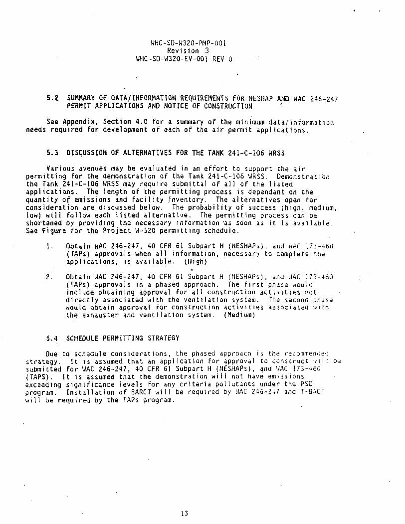
WHC-SD-W320-PMP-GOI Revision 3
WHC-SD-W320-EV-0G1 REV 0
5.2 SUMMARY OF DATA/INFORMATION REQUIREMENTS FOR NESHAP AND WAC 246-247 PERMIT APPLICATIONS AND NOTICE OF CONSTRUCTION
See Appendix, Section 4.0 for a summary of the minimum data/information needs required for development of each of the air permit applications.
5.3 DISCUSSION OF ALTERNATIVES FOR THE TANK 241-C-106 WRSS
Various avenues may be evaluated in an effort to support the air permitting for the demonstration of the Tank 241-C-1Q6 WRSS. Demonstration the Tank 241-C-106 WRSS may require submittal of all of the listed applications. The length of the permitting process is dependant on the quantity of emissions and facility inventory. The alternatives open for consideration are discussed below. The probability of success (high, medium, low) will follow each listed alternative. The permitting process can be shortened by providing the necessary information -as soon as it is available. See Figure for the Project W-320 permitting schedule.
1. Obtain WAC 246-247, 40 CFR 51 Subpart H (NESHAPs). and WAC 173-460 (TAPs) approvals when all information, necessary to complete the applications, is available. (High)
2. Obtain WAC 246-247, 40 CFR 61 Subpart H (NESHAPs), and WAC 173-460 (TAPs) approvals in a phased approach, the first phase would include obtaining approval for all construction activities not directly associated with the ventilation system. The second phase would obtain approval for construction activities associated with the exhauster and ventilation system. (Medium)
5.4 SCHEDULE PERMITTING STRATEGY
Due to schedule considerations, the phased approach is the•recommenced strategy. It is assumed that an application for approval to construct will be submitted for WAC 246-247, 40 CFR 61 Subpart H (NESHAPs), and WAC 173-460 (TAPS). It is assumed that the demonstration will not have emissions exceeding significance levels for any criteria pollutants under the PSO program. Installation of 8ARCT will be required by WAC 246-247 and T-8ACT will be required by the TAPs program.
13

WHC-SD-W320-PMP-001 Revision 3
WHC-SD-W320-EV-001 REV 0
(This page left intentionally blank.
14 G-23

WHC-SD-W320-PMP-Q01 Revision 3
WHC-SD-W32O-EV-0Q1 REV 0
6.0 MISCELLANEOUS ASSESSMENTS, PERMITS, AND APPROVALS i
In addition to the major regulatory programs discussed in this permitting plan, several miscellaneous assessments, permits, and approvals need to be addressed.
6.1 CULTURAL RESOURCE REVIEW
A Cultural Resource Review shall be performed prior to initiating the any potential surface disturbing activities onsite {36 CFR 800). The regulatory agency is RL. The Cultural Resource Review shall be submitted with the EA to RL.
• 6.2 EXCAVATION PERMIT
An excavation permit is required prior to initiating any potential surface disturbing activities onsita (36 CFR 300). The regulatory agency is RL. This permit will be prepared prior to construction of the tank farm interfaces.
6.3 ENDANGERED SPECIES ACT COMPLIANCE
A site assessment should be made to determine whether any planned activities have the potential to disturb any habitat used by wildlife prior to construction or habitat modification (50 CFR 402.6). The regulatory agency \> the Fish and Wildlife Service. For onsita construction, a biological survey is performed by VJHC. The survey report must accompany the EA when submitted to RL.
6.4 PREQPERATION MONITORING OF FACILITIES, SITES, AND OPERATIONS An environmental study must be conducted prior to start up of a new site,.
facility, or process which has the potential for significant adverse environmental impact (DOE Order 5400.1). The regulatory agency is RL. This monitoring shall be started at least one year prior to installation of the Tank 241-C-IQ6 WRSS.
6.5 LARGER ONSITE SEWAGE SYSTEM PERMIT Septic system approvals/permits (<14,500 gpd design capacity) - MAC 246-272
Plans and specification for construction of a new sanitary sewer system or modification of an existing system shall be submitted and approved by the DOH prior to construction. Once the installation is complete, a Professional Engineer registered in the State of Washington, must certify that the installation hrs been installed in accordance with Plans and Specifications approved by the DOH. In addition, an Operation and Maintenance Manual must be submitted to the DOH.
15 G-24

WHC-SD-W320-PMP-001 Revision 3
WHC-SD-W32O-EV-0O1 REV 0
{This page left intentionally blank.)
16 G-25

WHC-SD-W320-PMP-Q01 Revision 3
WHC-SD-W320-EV-001 REV 0
GLOSSARY
ABBREVIATIONS, ACRONYMS AND INITIALISMS
ADM Action Description Memorandum APCA- Benton, Franklin, Walla Walla Counties Air Pollution Control
Authority 8ARCT Best Available Radionuclide Control Technology CAA Clean Air Act CDR Conceptual Design Report CFR Code of Federal Regulations CX Categorical Exclusion DQE-HQ .U.S. Department of Energy-Headquarters OOH State of Washington Department of Health DS Determination of Significance DNS Determination of Nonsignificance DST Double-Shell Tanks EA Environmental Assessment Ecology State of Washington Department of Ecology EIS Environmental Impact Statement EPA U.S. Environmental Protection Agency FOMSI Finding of No Significant Impact IB Information Bulletin IPM Initial Pretreatment Module NAAQS National Ambient Air Quality Standards NESHAPs National Emissions Standards for Hazardous Air Pollutants MEPA National Environmental Policy Act HOC Notice of Construction NGO Notice of Deficiency .101 Notice of Intent - one for RCRA and one for NEPA PNL Pacific Northwest Laboratories PSD Prevention of Significant Deterioration PSE Preliminary Safety Evaluation RCRA Resource Conservation and Recovery Act RD&Q Research, Development, and Demonstration RL Department of Energy, Richland field Office SEPA State Environmental Policy Act SEIS State Environmental Impact Statement SQE Small Quantity Exemption TAPs Toxic Air Pollutants T-BACT Best Available Control Technology for Toxics TSD Treatment, Storage, and Disposal VOCs Volatile Organic Compounds WAC Washington Administrative Code-WRSS Waste Retrieval Sluicing System
GL-17 G-26

WHC-S0-W320-PMP-0O1 Revision 3
WHC-SD-W320-EV-001 REV 0
(This page left intentionally blank.)
GL-18 1-27

WHC-SD-W320-PMP-001 Revision 3
WHC-SD-W320-EV-001 REV 0 FIGURE - PROJECT W-320 PERMITTING SCHEDULE
I ISO*
-4
ail .
J.JUl
"ITT
1
s
111
n
U
U J'
- " 6 I-
u
31
n; i "•
II- -c 8
S * £ *
8
II 1
Si
It in
• i
hi:
:Jl
3 *
III «1
U
IS, 3r. n, a» '.I
~i . ; -r* a •Ttr
en 3 g i t * •»

WHC-SD-W320-PMP-001 Revision 3
WHC-SD-W32O-EV-0O1 REV 0
(This page left intentionally blank.)
Figure - 20 G-29

WHC-SD-W320-PMP-Q01 Revision 3
WHC-SO-W320-EV-001 REV 0 FIGURE - PROJECT W-320 PERMITTING SCHEDULE
a
"a" I
I
92
a 2 Ins- & *2
i * t g <
a M O
•in»2 yus tw
If
'6
I n j a.
Hi r
JI
; i
1! s-nn
=IF

WHC-SD-W320-PMP-001 Revision 3
WHC-SD-W32O-EV-0O1 REV 0
(This page left intentionally blankr)
Figure - 22 G-31

WHC-SD-W320-PMP-001 Revision 3
WHC-SO-W320-EV-001 REV 0 .ElfiURE - .PRfl.lFfT W-120 PERMITTINS SCHEDULE

WHC-SD-W320-PMP-001 Revision 3
WHC-SD-W32O-EV-001 REV 0
(This page left intentionally blank.)
Figure - 24 G-33 .

Tier KIV i ofT | M I JfVTT tun J «pf mr I •>* i J I i «ut i st>
iD2M)|i7 OfUl AIR iCI mam ml |liIHrttitt * $
fr»< oci i in>-I ptc I Jin I fft | " i m i " P W I wiV
U HOOK KJUtS
D£ If M i l t
C -5
(silk lH I H M r
UISS
!wra
l i i i i i t " " ! i £ i H i , l ^ i 0 » -4.$ WU. 12
ED mis
USILr A iCl KftHll
,Biai- -t£ fCiillCUL l i i i l tslS
U2it_ . . B _ , , i W umiCHlOH (PluSt # l l j i l C"l FIJ)H '
EMir
KE7E~Vif«« Cu IhiiSi I I I
ouinu J
c liUL
*Wt IUI IQI I |Fiu;
I 1 tu. FcAHll
ilciiCr MWHKS
I £ 421
c'liCl wr. „ . . IEPA. £1.0; D i t . 00. i l -PH #1
MO
m 'iiaos' i Iff U* HUK.C
taif-ft fctVltK Cii IHUSt 121
lUliit 22 OUlflOt U£IC< fi£0£KS IftuSf
I
-j.,'0 i1-* 1 C 106 Sl.UlL'illli
HUM

WHC-SD-W320-PMP-001 Revision 3
WHC-SD-W320-EV-0O1 REV 0
(This page left intentionally blank.)
Figure - 26 G-35

WHC-SO-W320-PMP-001 Revis ion 3
WHC-SQ-W32Q-EV-001 REV 0
APPENDIX 4
SUMMARY OF DATA/INFORMATION REQUIREMENTS FOR THE TANK 241-C-106 WRSS
Appendix - 27 G-36

WHC-SD-W320-PMP-001 Revision 3
WHC-SD-W320-EV-001 REV 0
(This page left intentionally blank.)
Appendix - 28 G-37

WHC-SO-W3 20-PMP-001 Revision 3
WHC-SD-W320-EV-001 REV 0
Section 1.0 - National Environmental Policy Act i
The minimum data/information requirements for NEPA documentation preparation are:
1. Conceptual or equivalent design information.
2: Preliminary Safety Evaluation (PSE) including a "source term" to determine health effects and accident scenarios.
3. In addition, any other related engineering, safety, or waste evaluation documents would be helpful in NEPA preparation.
Section 2.0 - State Environmental Policy Act
The minimum data requirements for preparation of the SEPA environmental checklist include:
1. Conceptual or equivalent design information is needed in order to prepare the SEPA environmental checklist.
2. Any NEPA documentation that has been prepared or will be prepared for the Tank 241-C-.106 WRSS.
3. Any other related engineering, safety, or waste evaluation document* would be helpful in SEPA environmental checklist preparation.
Section 3.0 - Resource Conservation and Recovery Act
The minimum data/informat ion requirements for the MOI. Parr A. Pic*: 3, and the RD2.D include:
NOI and Part A Permit Application
1. General nature of the process, capacities, justification of n<±>±u. iml volumes and flow rate is required for preparation of the NOI.
2. Preparation of the Part .A requires CDR level of detail
Part B Permit Application and RQ&O Permit Application
• I. Waste Minimization Plan
2. Building Emergency Plan
3. Tank Integrity Assessment (If Applicable)
4. Waste Analysis Plan
5. Process Plan
o. Contingency Plan
Appendix - 29 G-38

WHC-SD-W320-PMP-001 Revision 3
WHC-SD-W320-EV-001 REV 0
7. Waste Characterization Plan
8. Training Requirements
9. Closure and Post Closure Plan
10. CDR (or equivalent information)
11. 80% Design for submittal to regulators
12. Final "Approved for Construction" Design (PE stamped) for public review.
13. Air Permits require approval prior to issuance of the permit.
Section 4.0 - Clean Air Act
Detailed information on the treatment process, the emissions abatement system, the gaseous effluent monitoring system, and the nature of all gaseous emissions to the atmosphere is required for submissions made pursuant to the Clean Air Act. The information listed below is an abridged summary of the data/information needs for the MESHAP and WAC 246-247 permit applications and Notice of Construction. The appropriate' regulat ions and administrative guidance should be consulted for the detailed requirements.
Radioactive Emissions
MESHAP Permit
The 40 CFR 61.07 requires the application for approval to construct t.j include the following information:
1. Technical description of the facility and its operations
2. Size and location of the source
3. Oesign and operating capacity of the source
4. Method of operation (include process flow diagram)
5. Mature of all gaseous emissions to the atmosphere
• If a modification, the precise nature of the modification and estimates of emissions before and after completion
6. Technical description of emissions control s, ....em including relaasa rates and off site doses
Appendix - 30 G-39

WHC-SD-W32Q-PMP-001 Revision 3
WHC-SD-W320-EV-001 REV 0
WAC 246-247 Permit t
The WAC 246-247 requires the application for approval to construct to include the following information:
1. Facility Information
• Description of facility operations
Facility identification must be the same as that which appears on Source Registration Forms
2. Identification and listing of all sources consistent with the Source Registration Identification
3. Description of the source(s) • System function and area exhausted • Effluent system layout
• Efficiency values of each control device for removal of radioactivity
• Means and frequency of testing and inspecting effluent treatmenc system
• Operating mode (continuous or batch)
• Chemical and physical nature of Che emissions
• Stack or release point data
Stack diameter and height
• Building height, width and length
• Annual ambient average stack and ambient air temperatures
• Annual wind rose
Chi/Q data
• Annual average volumetric flow rate
• Annual average release rates Fraction of facility's inventory available for potential release to the air
Appendix - 31 G-40

WHC-SD-W320-PMP-001 Revision 3
WHC-SD-W320-EV-001 REV 0
Description of the effluent sampling/monitoring systems
• Stack flow measuring system
• Sample probes (isokinetic)
• Number and location of sampling points
• Sample 1ines
• Diameters, lengths, materials, bends, entry points into the effluent line, angle of entry into the effluent
i Sample flow regulation
Sampling media
Frequency of sampling (continuous or batch)
Frequency of sample collection
Calibration and audit schedules
5. Environmental sampling monitoring system
Sampling network (location, number, distance from release points)
Media sampled/monitored for the air pathway
Equipment used for sampling/monitoring, including sampler flow rate and collection media
Frequency of sampling/monitoring
Calibration and audit frequency
6. Hanford Site requirements for effluent sampling/monitoring system designs, procedures and quality assurance standards (appropriate standards and description of how they ar° ussd)
7. Effluent sample analyses including: methodology, procedure references, detection limits, quality assurance (including internal audit schedule and results)
3. Environmental sample analysis including methodology, procedure references, detection limits, quality assurance
9. Data from effluent and environmental monitoring programs, inducing background or local control data
Appendix - 32 G-41

WHC-SO-W'320-PMP-QOl Revision 3
WHC-SD-W32O-EV-0O1 REV 0
10. Demonstration of compliance » >
• Methodology used to demonstrate compliance • Input data used
• Source terms, release height, inhalation rate, maximally exposed individual, meteorology
• Results of method (effective dose equivalent for whole body and relevant organs)
• Description of internal standards used to ensure compliance with applicable state and federal laws and regulations
Nonradioactive Air Emissions
PSD Permit
The WAC 173-400 requires the application for approval to construct to include such information as:
1. Project location and emission source(s)
2. Design and operating parameters
• Hours of operation
• Normal and maximum production rates
Fuel requirements
• Raw material requirements
• Emissions control system
3. Emissions - Type and Quantity
• Representative emissions from the existing source (for modification) over the most recent two year period of operation
• . Projected actual controlled emissions at anticipated production rates and operating schedule for each pollutant at each emission point Projected potential controlled em;Ssions: amission rate when equipment is operating at maximum capacity 24 hours per day, 365 days per year, taking air pollution control equipment into account
Appendix - 33 G-42

4
WHC-SD-W320-PMP-001 Revision 3
WHC-SD-W320-EV-001 REV 0
4. 8ACT/BARCT assessment
Li terature search
• Control alternatives: comparison of efficiencies; energy, environmental, and economic impact analyses
• Summary
5. Analysis of current air quality at the proposed source location
• Presently existing ambient levels of the constituents being reviewed (from PNL data)
6. Analysis of the impact of the proposed source on ambient air quality
• Model description
AIRDOS - EPA
• Meteorological data (windspeed, direction, temperature)
• Modeling results
• Offsite dose
7. Demonstration that the proposed emission will not cause a violation of state or national ambient air quality standards (MAAOS)
• Oirect comparison of modeling results with NAAQS
8. Discussion of potential affects of the proposed project on factors influenced by air quality such as residential or commercial growth, vehicular traffic, vegetation, soils, acid deposition, visibility in sensitive areas, PSD increments, etc.
9. Construction schedule
Notice of Construction
The WAC 173-400 and 173-460 requires the application for approval to construct to include the following information:
1. SEPA checklist
2. Notice of construction form
3. Description of proposed source
• Bid specifications, rated capac.ity, inputs, outputs, and byproducts generated
Appendix - 34 G-43

WHC-SQ-W320-PMP-QQ1 Revision 3
WHC-SD-W320-EV-OQ1 REV 0
• Bid specifications, control efficiency, and operational requirements of the pollution control equipment
4
• Process flow diagram
• Estimate of stack emissions, including criteria and toxic air pollutants
Estimate of fugitive (nonstack) emissions
BACT/T-BACT analysis
Modeling
Appendix - 35 G-44

WHC-SD-W320-PMP-001 Revision 3
APPENDIX H
ENVIRONMENTAL ASSESSMENT, TANK 241-C-106 PAST-PRACTICE SLUICIN& WASTE RETRIEVAL
DOE/EA-XXXX
H-l

WHC-SD-W320-PMP-001 Revision 3
This page intent ional ly l e f t blank.
H-2

WHC-SD-W320-PMP-00I Revision 3
CORRESPONDENCE DISTRIBUTION COVERSHEET
Author
W. J. Rued, 376-5266
Addressee
L. Erickson, RL
Correspondence Ha.
9353388.1
subject: ENVIRONMENTAL ASSESSMENT: TANK 241-C-106 PAST PRACTICE SLUICING AND WASTE RETRIEVAL, HANFORD SITE, RICHLAND, WASHINGTON
INTERNAL DISTRIBUTION Approval Date Nam* Location
yy«
• I - ONLY 376-3750 BJH
Correspondence Control A3-01 X Presi dent's Office 83-01 A. T. Alstad Rl-49 X B. F. Archer H6-26 X J. W. Bafley S4-55 X D. E. Bowers S6-01 X M. A. Cahill (2) S4-57. . X J. C. Conner H4-61 X R. H. Engelmann H6-25 X K. 8. Ferlan S4-55 X C. J. Geier R2-50 X J. P. Harris S4-55 X J. M. Henderson S4-55 X G. W. Jackson H6-21 P. J. Mackey B3-15 W. J. Rued H6-25 X M. A. Siano G6-02 X G. A. Symons S4-55 X 8. D. Williamson 83-15 X EPIC (NEPA Files) H6-08 X
H-3 cnnrt, H T /»">/<»o*

WHC-S0-W320-PMP-001 Revision 3
® We$tln#iQus* Hanford Company
P.O. 8ox 1970 flicnland. WA 99352
December 2, 1993 9358388.1
Mr. I. Erickson, Oirector Tank Waste (Disposal Division U.S. Department of Energy Richland Operations Office Richland, Washington 99352 Dear Mr. Erickson: ENVIRONMENTAL ASSESSMENT: TANK 241-C-106 PAST PRACTICE SLUICING ANO WASTE RETRIEVAL, HANFORD SITE, RICHLAND, WASHINGTON Resubmitted for your review is the subject Environmental Assessment (EA) (Enclosure 1). The EA has been revised in response to comments generated by the U.S. Department of Energy, Richland Operations Office (RL). The proposed action, identified as Project W-320, involves sluicing the majority of the high-heat waste from tank 241-C-106 and transferring it to tank 241-AY-IQ2, a double-shell tank. This action would result in the cessation of cooling water additions to tank 241-C-1Q6, and would decrease the amount of liquid available for release should the tank start to leak. The Hanford Tank Waste Remediation System Safety Initiatives call for delegation of approval authority for this EA to the Manager, RL. Once provided, this delegation will represent the first time that RL has been allowed to determine the adequacy of an EA, and will be critical in meeting the EA approval schedule. Should you require further information, please contact Mr. J. P. Harris an 372-1237 or Mr. R. H. Engelmann of the National Environmental Policy Act Documentation Function on 376-7485.
Very truly yours,
H^u^ -J. M. Henderson, Manager Single-Shell Tank Retrieval Projects Tank Waste Remediation Systems say Enclosures - 2
at
RL - C. A. Ashley R. W. Brown R. M. Carosino

WHC-SD-W320-PMP-001 Revision 3
DOE/EA - XXXX
ENVIRONMENTAL ASSESSMENT
TANK 241-C-106 PAST-PRACTICE SLUICING
WASTE RETRIEVAL
HANFORD SITE, RICHLAND, WASHINGTON
U.S. DEPARTMENT OF ENERGY
NOVEMBER 1993
H-5

WHC-SD-W320-PMP-001 Revision 3
This page intentionally left blank.

WHC-SD-W320-PMP-001 Revision 3
U.S. Department of Energy Execuiiva Summary
Executive Summary
This Environmental Assessment (EA) was prepared to analyze the potential impacts
associated with the proposed action, past-practice sluicing of underground Tank 241-C-1Q6
(Tank C-106), a single-shell tank (SST). Past-practice sluicing is defined as the mode of
waste retrieval used extensively in the past at the Hanford Site with large underground waste
tanks, and involves introducing a high-volume, low-pressure stream of liquid to mobilize
sludge waste prior to pumping. This EA describes the proposed action, affected
environment, and possible alternatives, and also provides an analysis of the potential
environmental impacts.
Past-practice sluicing of Tank C-106 is proposed because the waste is classified not
only as transuranic and high-level, but also as high-heat, which is caused by the radioactive
decay of strontium. Large volumes of water have been added to the tank to provide
evaporative cooling of the waste and to prevent the sludge from drying out. In the absence
of these water additions, the heat load in Tank C-106 might exceed allowable temperature
limits with the potential for structural failure of the tank. The tank is currently classified as
sound, but there is a concern that should the tank start leaking, continued water additions
could result in an increased amount of waste released to the environment.
H-7

WHC-SD-W32Q-PMP-QQi Revis ion 3
U.S. Deportment of Energy Executive Summary
The purpose of the proposed action is to:
• Remove at least 75 percent of the high-heat waste which would reduce the tank
heat load to less than 11.72 kilowatts (kW) (40,000 British thermal units [Bru])
per hour. Water additions could then be stopped, and the tank removed from the
safety "Watchlist"
• Demonstrate one form of SST retrieval by October 1997 as called for in the
Hanford Federal Facility Agreement and Consent Order (Tri-Party Agreement)
Milestone M-07-00, "Initiate Full-Scale Demonstration Retrieval Technology,''
(Milestone M-45-04 'Complete SST Waste Retrieval Demonstration,' under the
proposed revisions to the Tri-Party Agreement).
Past-practice sluicing would be accomplished by transferring waste from Tank C-L06 to
the receiver tank, Tank 241-AY-102, an underground double-shell tank (DST). Two transfer
lines would connect the tanks. One line would carry the slurry (the sluiced waste) to the
DST, and the other would carry the supemate liquid from the DST, which would be used to
mobilize the waste in Tank C-106 to facilitate pumping and waste transfer. The primary
equipment necessary for this action would include pumps in each of the t?nks, siuicers to
remotely aim the sluice streams in Tank C-106, a slurry distributor in the DST, an air
ventilation system on Tank C-106, and additional monitoring devices.
H-8

WHC-SD-W320-PMP-0Q1 Revision 3
U.S. Department of Energy Executive Summary
Several alternatives to the proposed action are briefly discussed in this document. They
include Batch Transfer, Once Through—No Recycle, Limited Mixer Pump, Recirculate
Within a SST Via Mixer Pump, Internal Recirculation, Hydraulic Mining, Center Pivot
Dredge, and No-Action. These alternatives were examined and found to either pose an
unacceptable risk to induce a tank leak, or failed to meet one of the two requirements of this
project. The two requirements include reducing the heat load in Tank C-106 to below
11.72 kW (40,000 Btu) per hour, and being able to start retrieval by October of 1997.
Impacts from the proposed action were found to be small in comparison to
Hanford Site operations as a whole. Environmental impacts to the air and water would be
within all applicable standards. Human health effects also would fall within acceptable
ranges, and would be in compliance with all standards. No impact is expected to threatened
or endangered wildlife species, critical or sensitive habitat, or cultural or historical resources.
Impacts from accidents were examined and evaluated. The worst-case scenario for an
onsite individual involved the failure of the High-Efficiency Particulate Air unit on
Tank C-106 as a result of a Design Basis Earthquake. The scenario assumes that the failure
is not detected for 30 minutes. The onsite individual has been calculated to receive a dose of
30.5 roentgen equivalent man (rem) Ef^ t ive Dose Equivalent (EDE). The probability of
that individual developing a latent cancer fatality (LCF) from this dose rate would be
1.2 x 10"*. The wont case scenario for offsite populations would involve a break in the
waste transfer line which also is not detected for 30 minutes. The maximally exposed offsite
H-9

WHC-S0-W320-PMP-QQ1 Revision 3
U.S. D6(MUtment of Energy Executive Summary
individual has been calculated to receive a dose of 1.2 rem EDE, which would represent a
probability of 6.0 x 10"4 that the individual would develop an LCF. The effect to the entire
offsite population from this scenario would be a calculated 4.3 LCFs.
H-10

WHC-SD-W320-PMP-001 Revision 3
U.S. Department of Energy Glossary
Glossary
Acronyms and Initialisms
ALARA Btu CAA CPS CRR DBE DOE DOH DST EA Ecology EDE EPA HEPA HVAC LCF kW NRC RCRA rem SST Tri-Party Agreement WAC
As Low As Reasonably Achievable British thermal unit Clean Air Act of 1970 Criticality Prevention Specification Cultural Resources Review Design Basis Earthquake U.S. Department of Energy State of Washington Department of Health double-shell tank Environmental Assessment State of Washington Department of Energy effective dose equivalent U.S. Environmental Protection Agency High-Efficiency Particulate Air heating, ventilation, and air conditioning latent cancer fatalities kilowatts Nuclear Regulatory Commission Resource Conservation and Recovery Act of 1976 roentgen equivalent man single-shell tank Hanford Federal Facility Agreement and Consent Order Washington Administrative Code
H-ll

WHC-SD-W320-PMP-001. Revision 1
U.S. Department of Energy Glossary
This page intentionally left blank.

WHC-SD-W320-PMP-001 Revision 3
U.S. Department o( Energy Table of Contents
Table of Contents
1.0 Purpose and Need for Agency Action l-l
2.0 Description of the Proposed Action 2-1 2.1 Background 2-1 2.2 Proposed Action 2-2 2.3 Related Actions .2-3
3.0 Alternatives to the Proposed Action 3-1
4.0 Affected Environment 4-1 4.1 Hanford Site 4-1 4.2 Cultural and Biological Resources 4-1
5.0 Environmental Impacts 5-1 5.1 Impacts from Routine Sluicing of Tank C-106 5-1 5.2 Impacts from Accidents 5-3 5.3 Cumulative Impacts . . . - . . ' 5-7
6.0 Permits and Regulatory Requirements 6-1
7.0 Agencies Consulted 7-1
8.0 References 8-1
Appendices
A. Cultural Resources Review (HCRL #93-200-111) A-l B. Ecological Survey (#93-200-40) . . B-1
H-13

WHC-SD-W320-PMP-001 Revision 3
U.S. D«p«itmea( of Energy Table of Concent*
List of Figures
1. Hanford Site Showing Tank 241-C-1Q6 Location. F-l 2. Figure 2. Typical Single- and Double-Shell Tank Configuration F-2 3. Typical Tank-To-Tank Sluicing (With Underground Transfer Lines) F-3 4. Proposed Location of Waste Transfer Lines F-4 5. Proposed Buried Pipeline Configuration F-5 6. Typical Sluicer Configuration F-6
List of Tables
1. Potential Accident Scenarios 5-3 2. Radiological Dose Consequences . 5-4

WHC-SO-W320-PHP-001 Revision 3
U.S. D«p»rtm«nt of Energy Purpo*e and Need for Agency Action
1.0 Purpose and Need for Agency Action
The purpose of the proposed action is to eliminate safety concerns with the storage of high-heat waste in Tank 241-C-106 (Tank C-106), and to demonstrate a tank waste retrieval technology. The proposed action would retrieve the soft, high-heat sludge waste from Tank C-106, a single-shell tank (SST), by way of sluicing. This is being proposed for the following reasons:
• The heat generation for Tank C-106 is estimated to be 32.24 plus or minus 5.86 kilowatts (kW) (110,000 plus or minus 20,000 British thermal units [Btu]) per hour (WHC 1993a). The heat is produced from the radioactive decay of radionuclides present in the waste, namely strontium-90. This decay heat is being removed by way of evaporative cooling. Approximately 22,700 liters (6000 gallons) of water are added to the tank each month for this purpose. It is believed that without active cooling, temperatures in the tank would exceed established limits and eventually affect the structural integrity of the tank with a possible breach of containment. Sluicing would remove the majority of high-heat waste from die tank, and would lower the heat generation to below 11.72 kW (40,000 Btu) per hour (the point at which active cooling is no longer required).
• The continued addition of cooling water to the tank increases the amount of waste that could disperse into the soil column if Tank C-106 starts to leak. Retrieval of the high-heat waste would eliminate the practice of adding cooling water to the tank and the need for active ventilation
• Ha/tford Federal Facility Agreement and Consent Order (Tri-Party Agreement) Milestone M-07-00, "Initiate Full-Scale Demonstration Retrieval Technology," calls for the demonstration of one- retrieval technology by October 1997. Sluicing has been identified as a reference retrieval technology for SST waste. Under the proposed changes to me Tri-Party Agreement, this requirement would be covered under two milestones, M-45-03 "Initiate Sluicing Retrieval of Tank C;106" and M-45-04 "Complete SST Waste Retrieval Demonstration.''
H-15

WHC-SD-W320-PMP-001 Revision 3
U.S. Deputmeat of Eaergy Purpow tad Need for Agency Accioo
This page intentionally left blank.

WHC-SO-W320-PMP-0O1 Revision 3
U.S. Department of Energy Description of the Proposed Action
2.0 Description of the Proposed Action
2.1 Background The National Defense Authorization Act for Fiscal Year 1991, Public Law 101-510,
Section 3137, "Safety Measures for Waste Tanks at Hanford Nuclear Reservation," mandates that the U.S. Department of Energy (DOE) develop plans to respond to safety issues associated with die underground waste storage tanks on the Hanford Site, and to report progress of implementation of these plans to Congress. The tanks identified as having safety issues associated with them belong to die safety "Watchlist." The report containing the response plans has been prepared as Status Report on Resolution of Waste Tank Safety Issues at the Hanford Site (WHC 1993b), which identifies Tank C-106 as one of the "Priority I," safety issues at the Hanford Site.
The proposed action would involve sluicing the waste from Tank C-106, a SST, and transferring the waste to Tank 241-AY-102 (Tank AY-102), a double-shell tank (DST) through one of the two proposed double encased (pipe-in-pipe design), bermed lines. Past-practice sluicing involves introducing a high-volume, low-pressure stream of liquid to mobilize sludge waste prior to pumping. Tank C-106 is located in the 200 East Area (Figure 1). Tank C-106 is 23 meters (75 feet) in diameter, and is constructed of reinforced concrete with a carbon-steel liner on die tank bottom and sides. The tank has a 31-centimeter (12-inch) thick dished bottom, and a useable waste depth of approximately 4.8 meters (16 feet) at the sidewall. The dome of the tank is constructed of 38-centimeter (15-inch) uiick reinforced concrete. Tank C-106 was constructed between 1943 and 1944, and has the capacity of approximately 1.9 million liters (500,000 gallons). Figure 2 shows the typical configuration of a SST.
The waste in Tank C-106 consists of 746,000 liters (197,000 gallons) of sludge. The waste is stratified into two layers. The top layer consists of 655,000 liters (173,000 gallons) of sludge containing a sufficient amount of strontium to be considered high-heat waste (WHC 1993c). The bottom layer consists of 91,000 liters (24,000 gallons) of tow-heat producing hardened material. This retrieval action would need to remove approximately 75 percent of the high-heat waste to lower me heat output of the remaining waste to less than 11.72 kW (40,000 Btu) per hour. As a demonstration of a waste retrieval technology, this project would attempt to remove as much waste as possible beyond this 75 percent.
In addition to producing significant quantities of heat, die waste in Tank C-I06 has greater than 100 nanocuries per gram transuranic content (WHC 1993c). This qualifies the sludge as both a high-heat and transuranic waste (WHC I993a). The chemical composition of die sludge also classifies the contents of die tank as a "listed waste" in accordance with Washington Administrative Code (WAQ 173-303. The heat generation rate for this sludge is estimated to be 32.24 plus or minus 5.86 kW (liO-,000 plus or minus 20,000 Btu) per hour (Bander 1993).
H-17

WHC-SD-W320-PMP-001 Revision 3
U.S. Department of Energy Description of (be Proposed Action
Tank AY-102 was built in the late 1970s, and has an operational capacity of 3.7 million liters (980,000 gallons). Tank AY-102's waste comes from a variety of sources and is considered transuranic and nonorganic, making it compatible with the waste from Tank C-106. The fact that Tank AY-102 is a DST, which provides an additional barrier against the release of the waste to the environment, and has an increased capacity to dissipate heat, makes it an adequate receiver tank for the waste in Tank C-106. Figure 2 shows the typical configuration of a DST.
2.2 Proposed Action
The sluicing operation would involve introducing a high-volume, low-pressure stream of liquid (supernate) to mobilize the sludge waste in Tank C-1Q6 and to prepare it for pumping. Two remotely aimed " sluicers" would be installed in Tank C-106 at separate locations to ensure full sluicing coverage of the waste. The mobilized waste would be retrieved from Tank C-106 with a submersible pump that would transfer the waste to Tank AY-102 through one of two proposed, double encased pipelines. These pipelines, which would connect the two tanks, would measure approximately 0.4 kilometer (0.25 miles) in length. Figure 3 depicts tank-to-tank sluicing while Figure 4 shows the location of the proposed waste transfer lines. The waste would be deposited in die receiver tank where the majority of the heavier solid waste particles would settle to the bottom while the liquid portion would remain on top to be recycled to Tank C-106 as the liquid sluicing agent. A sluice pump would transfer supernate from Tank AY-102 to Tank C-106 through one of the two, newly installed, pipelines. These pipelines would be buried and covered with an earthen berm to limit personnel dose exposure (Figure 5).
The sluice pump in Tank 102-AY would deliver 1,324 liters (350 gallons) per minute of supernate to the sluicing nozzles in Tank C-106 with a pressure of 12.5 kilograms per-square-centimeter (130 pounds per-square-inch), and at a temperature of approximately 83 °C (180 °¥). Two sluicers (Figure 6) would be installed in Tank C-106, and would use the supeniate from Tank AY-102 to break up the sludge waste. One siuicer would operate in the existing sluice pit, while the other would operate in the existing pump pit. Valves would direct the diluted supernate liquid to one or both of the stuicers. During most of the waste retrieval operations, only one siuicer would operate at any given time. However, towards the end of the retrieval operations, both might operate simultaneously to facilitate waste mobilization in hard to reach locations.
A new submersible pump would be installed in Tank C-106 to transfer the slurry (i.e., the sluiced waste) to Tank AY-102. To allow for slurry elevation changes, the slurry transfer pump would be manually adjusted to maintain sufficient suction-head pressure. The sluicing operations would start from the center of the tank and work to the outside by remotely adjusting the angle of the sluicers. This design would minimize the time that the tank liner is directly exposed to the sluice stream, and minimize the potential for a sluicing-induced tank leak.
H-

WHC-SD-W320-PMP-001 Revision 3
U.S. D«partment of Energy Inscription of tha Proposed Action
The slurry would be pumped into the txznsfer line and deposited into Tank AY-102. A slurry distributor would evenly spread the Tank C-106 waste solids in Tank AY-102. This would eliminate any criticality issues, and would provides a more uniform heat source in Tank AY-102. The distributor also would provide a siphon break to the transfer line back to Tank C-106.
2.3 Related Actions
Prior to the actual sluicing operations, several actions would be required to prepare the tanks for the insertion of the pumps and/or equipment. The existing equipment in the pump and sluice pits of Tank C-106 must be removed and stored at the Hanford Site for subsequent treatment and disposal. The inside of these pits would require cleaning, and the application
• of paint or fiber to die surface, to provide a surface that can be more easily decontaminated.
To minimize releases to the atmosphere, the proposed action also would install a High-Efficiency Particulate Air (HEPA) filtration system for Tank C-106. Additional filtration elements (which would include mist eliminators and gas filtration units) would be included in this system as required to meet regulatory release limits. New exhaust ductwork would be designed and installed to discharge through the new filtration system. The oid ventilation system and ductwork would remain in place and operational for Tank 241-C-105 and for Tank C-106 major maintenance operations. During these infrequent major maintenance operations, approximately 75 cubic meters (2500 cubic feet) per minute would be discharged through this ventilation system. The new filtration system would discharge a maximum of approximately 9.9 cubic meters (350 cubic feet) per minute during normal operations.
To control the temperature and humidity of the Tank C-106 vapor space during sluicing, the proposed action would install a recirculating air system. This recirculating system would consist of a condenser, a dehumidification coil, and a recirculation fan.
Additional instrumentation would be required in both tanks (Tanks C-106 and AY-102) and in die transfer lines between the tanks. Tank C-106 would receive instrumentation that would monitor tank pressure to ensure confinement. An in-tank imaging system would be provided to locate remaining tank sludge as well as indicate the location of the siuicers. Temperature monitoring would be provided by using either a thermocouple tree, stiffened to withstand sluicing liquid impact forces, or an infrared system. Sluicing pump control and status instrumentatinn also would be provided. A double-wide trailer would be installed outside the 241-C Tank Farm, which would serve to house centralized monitoring and control instrumentation. Additional monitoring devices would be installed in Tank AY-102 as needed. Leak detection would be provided for the new transfer lines and the pump pits.
Support services, in the form of raw water, sanitary water, electrical power, telecommunications, and hoisting hardware, would be provided. The use of existing septic systems would be considered. A sanitary catch tank, sized for 2 weeks of operation, would be provided should it be determined that existing facilities are inadequate. Standby power and/or uninterruptable power supplies would be orovided as required. Chemical additions, to

WHC-SD-W320-PMP-0Q1 Revision 3
U.S. Dcpartmoot of Energy Description of the Proposed Actioa
maintain the waste within operating specifications for DST storage, would be distributed through an existing riser in Tank AY-102.
The project has a maximum design life of 2 years. After the retrieval operation is complete, the used equipment and waste transfer lines would be decontaminated and stored for future treatment and disposal. Other project waste would be disposed of in a properly sited landfill in accordance with all applicable state and federal guidelines.

WHC-SD-W320-PMP-001 Revision 3
U.S. Department of Energy Alternatives-to the Proposed Action
3.0 Alternatives to the Proposed Action
Sluicing alternatives to the proposed action were identified and described in Appendix F of the Tank 106-C Sluicing Letter Report (WHC 1993e). The sluicing alternatives mentioned, including the No-Action Alternative, are listed below.
• Batch Transfer. This option would utilize a 189;000 liter (50,000 gallon) accumulation tank which would hold both the supernate from Tank AY-102 and the slurry from Tank C-106 alternately. This supemate would be used as the sluicer fluid for Tank C-106 waste. When enough solids are pumped to the accumulation tank, the material would be batch transferred to Tank AY-102. The accumulation tank would then be refilled with supernate from Tank AY-102, and the cycle repeated.
• Once Through—No Recycle. This alternative would use a tank truck to supply the sluicing medium to mobilize the solids in Tank C-106, which are then pumped to the receiver tank. With no recycling, the amount of liquid pumped to the receiver tank would be larger relative to the preferred alternative. Some of this excess liquid would be pumped from the DST for additional treatment or storage (i.e., sent to an evaporator or another DST with more available space). This alternative, one of several which would use a tank truck, would allow for continuous operation.
• Limited Mixer Pump. This alternative is similar to the Once Through Alternative-No Recycle described above in that it would utilize a tank truck to provide the sluicing agent. This alternative, however, would use sluicers and a specially designed combined mixer and transfer pump to mobilize a portion of the solids in Tank C-106 in a bowl-shaped depression (utilizing the remaining solids as an additional barrier to tank leakage). The homogenized slurry would men be transferred to the receiver tank in batches to reduce the amount of extra liquid waste produced. While this alternative would not be expected to produce as much additional waste as the Once Through—No Recycle Alternative, it still would require more storage space than the preferred alternative or the Batch Transfer Alternative.
• Recirculate Within a SST Via Mixer Pump. Again, a tank truck would be used to supply the waste mobilizing agent. However, sluicers would not be used in this option. Instead, two mixer •*,,mps would use the introduced liquid to mobilize all of the solids in Tank C-106 into a homogenous slurry before transfer. This option would have roughly the same waste space requirements as the preferred alternative, however, there are several drawbacks that make this option unattractive. These drawbacks include: higher heat input to the waste due to additional mixing and agitation; increased environmental risk due to possible damage to the tank from the mixing pump outlet spray impinging on the tank walls and a much higher liquid inventory maintained in Tank C-106 during the retrieval operation; the need for an additional 107-centimeter (42-inch) riser; and a longer design and testing period.
H-21

WHC-S0-W320-PMP-001 Revision 3
U.S. Dop*rtmeot of Energy Alternative to the Proposed Actioa
• Internal Recirculation. The last alternative to use a tank truck, internal recirculation, would use a portion of the slurry (i.e., the already-sluiced waste) as an additional mobilization agent. Some of the slurry would be pumped to the receiver tank and some would be fed back into the sluicers, thereby limiting the amount needed from the tank truck. As with the other alternatives that use a tank truck, the amount of slurry waste would be somewhat greater than that of the preferred alternative.
• Hydraulic Mining. This alternative would use a variation of a technique used in the mining industry. A crane would lower a mining tool that would penetrate the waste and shoot a high-pressure stream of water laterally. A slurry inlet port would pump the slurry out to the receiver tank, creating a waste cavity in the section of waste desired. More complex dian the preferred alternative, this unproven alternative would have the potential for the greatest waste minimization of any of the alternatives. However, the amount of time required to develop and test the method would be much greater than any of the other alternatives.
• Center Pivot Dredge. Dredging involves utilizing a 1.5-meter (5-foot) opening to allow mechanical dredging equipment to access the tank. This option involves the highest cost and complexity, and yefc provides die lowest probability of success. In addition, the amount of time to test and develop appear to be prohibitive. The exposure to workers is anticipated to be higher due to the 1.5-mete.- (5-foot)
. opening. Concerns on exceeding tank dome weight limits also exist with this option. The potential for worker exposure is greater and the amount of equipment to be decontaminated and decommissioned is larger.
• No-Action. This alternative would involve leaving the high-heat waste in Tank C-1Q6 and continuing to add large amounts of cooling water.
Of the sluicing alternatives presented above, only the proposed action and the Batch Transfer Alternative meet the two requirements considered essential to addressing the concerns mentioned in Section 1.0. These requirements consist of reducing the heat toad in Tank C-106 to less than 11.72 kW (40,000 Btu) per hour and choosing a sluicing method mat would be able to start retrieval by October of 1997. The other alternatives were not able to meet one or both of these requirements and, therefore, were not examined further. The Batch Transfer Alternative, while it meets die two requirements, would entail more design, procurement and construction costs, and would be less likely to meet the start date.
The No-Action Alternative would result in maintaining Tank C-106 in its present condition. No waste transfer operations would be performed, and the high-heat producing waste would continue to generate excessive thermal loads. In order to maintain the temperature of the tank to levels below the point where the tank structural integrity would-not be affected by excessive heat, large volumes of cooling water would continue to be added. Alternative means of cooling die waste, such as using a sprinkler system, an air

WHC-SD-W320-PHP-001 Revision 3
U.S. Department of Enerfy Alternative* to th« Proposed Action
chiller (which would introduce cooled air into the tank), or a combination of the two, are currently being examined. These cooling methods are designed to be used as a contingency plan should the tank start to leak. Because Tank C-106 has reached the end of its design life, the possibility of a tank leak is fairly high and will increase over time. The continued addition of cooling water, which would likely proceed under the No-Action Alternative, would increase the total amount of possible contamination which could leak into the soil column. No matter which cooling method is used (either the addition of cooling water or the development and use of an air chiller), die problem of high-heat producing waste would persist and die milestone for die demonstration of a waste retrieval technology would not be met.
No other reasonable alternatives to past-practice sluicing have been identified.
H-23

. WHC-SD-W320-PMP-001 Revision 3
U.S. Department of Energy Alternative* to tno Proposed Action
This page intentionally left blank.

WHC-SD-W320-PMP-001 Revision 3
U.S. Department of Energy Affected Environment
4.0 Affected Environment
4.1 HanfordSite Tanks C-106 and AY-102, are located in the 200 East Area of the approximately
560 square mile (1450 square kilometer) semi-arid Hartford Site in Southeastern Washington State (Figure I). The 200 East Area is approximately 10 kilometers (6 miles) west of the Columbia River, the nearest natural watercourse. The nearest population center is the City of Richland, approximately 32 kilometers (20 miles) to the south. The 200 East Area is not located within or adjacent to a wetland or in a 100- or 500-year floodplain. While there are no plants or animals on the federal list of "Endangered and Threatened Wildlife and Plants" (50 CFR 17) that are found in die immediate vicinity of the tank farms addressed in diis document, there are several species of both plants and animals at the Hanford Site which are under consideration for formal listing by the Federal Government and the State of Washington. None of these potentially federal- or state-listed threatened or endangered species would be adversely impacted by die proposed action because they do not exclusively use die area immediately surrounding the tank farms. The geology of the site where the proposed action would take place is typical of'die 200 Areas. The surface is covered with loess and sand dunes of varying diickness, although die tank farms and the majority of the area between diem is composed of a disturbed gravel layer. Under the surface layer, in ascending order, are basement rocks of undetermined origin, the Columbia River Basalt Group with intercalated sediments of the Ellensburg Formation, the Ringold Formation, the Plio-PIeistocene unit, and the Hanford Formation. The depth to groundwater for the 200 East Area is 75 meters (246 feet). Groundwater flow direction is generally in an easterly and southeasterly direction, toward the Columbia River (PNL 1992a).
The Hanford Site has a mild climate widi 15 to 18 centimeters (6 to 7 inches) of annual precipitation, and infrequent periods of high winds of up to 128 kilometers (80 miles) per hour. Tornadoes are extremely rare; no destructive tornadoes have occurred in the region surrounding the Hanford Site. The probability of a tornado hitting any given waste management unit on the Hanford Site is estimated at 10 chances in 1 million during any given year.
Additional information regarding the Hanford Site can be found in characterization documents (PNL 1992b).
4.2 Cultural and Biological Resources
The Hanford Site is known to be rich in cultural resources, and contains many well-preserved archaeological sites dating back to both prehistoric and historical periods, and many native American people still diink of it as their homeland.
H-75

WHC-SD-W320-PMP-Q01 Revision 3
U.S. Department of Energy Affected Environment
Over 10,000 years of human activity have left extensive archaeological deposits along the Columbia River shoreline and at well-watered inland sites. By virtue of their inclusion in the controlled Hanford Site, archaeological deposits have been spared some of the severe disturbances that have befallen unprotected sites in the area.
The proposed activities, past-practice sluicing and waste transfer operations, are not known to occur in an environmentally sensitive area. The tank farms affected by the sluicing and waste transfer actions have been reviewed and have not been found to contain any cultural resources. Appendix A contains the Cultural Resources Review (CRR) for the impacted area and states that, due to the highly disturbed nature of the area, no cultural resources are expected. If the work being proposed uncovers any items of significance, work would be halted until proper mitigation measures are taken. Additional information regarding the Hanford Site's cultural and biological resources can be found in characterization documents (PNL 1992b).

WHC-SD-W320-PMP-001 Revision 3
U.S. Department of Energy Environmental Impacts
5.0 Environmental Impacts
This section presents information on those potential environmental impacts that have been identified as a result of activities being proposed for routine past-practice sluicing of waste from Tank C-106 to Tank AY-102.
5.1 Impacts From Routine Sluicing of Tank C-106
It is expected that proper controls on the tank ventilation systems would operate in accordance with the Clean Air Act of 1970 (CAA) requirements for gaseous and particulate discharges to the atmosphere. The tank ventilation system would maintain a negative pressure inside of Tank C-106. This would keep the gaseous and particulate contents inside the tank in the event of planned or unforeseen openings of the tank risers. HEPA filtration units would be employed at the Tank C-106 exhaust stack, which would satisfy As Low As Reasonably Achievable (ALARA) principles, and meet state and federal regulatory requirements.
* Most of the liquid necessary for the sluicing operations would be obtained from and
returned to Tank AY-102. The overall amount of liquid in Tank C-106 would not increase substantially during sluicing operations, because the amount of material that would be sluiced is approximately equal to the amount of supernate added. Additional liquid, which would consist primarily of clean water, might be required for sluicing-line cleanout, but would not be a significant increase in total volume used, and would be within the receiving tank's storage capacity. Sanitary services for the support trailer would consist of a buried catch tank designed to collect sanitary waste for a 2 week period.
The sluicing line and slurry transfer line would comply with Resource Conservation and Recovery Act of 1976 (RCRA) criteria, and include full pfpe-in-pipe containment with leak detection. The sluicing line valve box would be designed to have a drain system capable of handling a worst-case spill scenario. This drain system also would serve to prevent releases to the environment. Initially, sluicers would direct the diluted supemate toward the center of die tank. As the retrieval operation proceeds, the sluicers would be directed outward. This would minimize the time that the tank liner is directly exposed xo the sluice stream, and minimize the potential for a sluicing-induced tank leak.
The proposed action would result in the generation of sr 4ld waste during the early stages of die project. Such waste would be surveyed and disposed of in the Hanford Site Solid Waste Landfill if uncontaminated, or another applicable, permitted location if found to be contaminated with hazardous or radioactive constituents. At the completion of activities, noncontaminated equipment would be excessed where applicable, while contaminated materials and components would be packaged and stored in a permitted facility as is the current practice.
H-27

WHC-SD-W320-PMP-001 Revision 3
U.S. Department of Energy Environmental Impacu
Trenching would be required for power and instrumentation control cable lines for the sluicing operations. The proposed action also would include the installation and operation of a double-wide trailer (two single, modular trailers combined into one facility). This facility would be located immediately adjacent to the 241-C Tank Farm. An Excavation Permit would be required for the buried waste transfer lines and the tie-down operations needed for the double-wide trailer, and would trigger a CRR. Appendix A of this document is the CRR for this project and states that no cultural resources are expected to be disturbed.
The area where the work is to be performed (i.e., the 241-C and 241-AY Tank Farms) is a developed, highly disturbed area, and is currently under vegetation management. The pipelines would be buried and covered with an earthen berm for shielding. Neither the pipelines nor the support facility would have a negative impact on plant or animal species. The work would not disturb any sensitive or critical habitat. There are no animal species of special concern that are known to use the area exclusively. The 200 East Area is not located in a floodplain, and die tank farms are not located on land that could be considered wetlands. Appendix B consists of the Ecological Survey which states chat no adverse impacts are expected to any plane or animal species because the proposed action takes place in such a highly disturbed location.
The proposed action would likely result in a minor release of particulates from construction activities needed to prepare the tanks for sluicing. These particulates, which consist chiefly of dust, would be mitigated by proper dust controls whenever necessary. Thermal discharges to the environment would be generated by equipment and vehicle exhaust, but can be considered minor when compared to sitewide thermal releases. Noise levels would rise in the vicinity of the 241-C and 241-AY Tank Farms during the sluicing operations, but would return to present levels when the project is finished. The equipment to be used (e.g., steel and other metals for piping and enclosures chat are necessary for sluicing operations) represents a long-term commitment of nonrenewable resources. A Radiation Work Permit would be required for work within the tank farms.
During normal transfer operations, no releases would be expected. During jumper change operauons, small residual amounts of radioactive material would be available for release. Large leaks within the pump and sluice pits would be detected and controlled by special instrumentation. Pit drains would return leaked wastes to either Tank C-106 or Tank AY-102 for compatible waste storage. Leaks resulting in measurable accumulation of solution on the floor of the pits would be detected and the waste returned co the tank. For smaller leaks, detection would be accomplished by visual inspections or engineered features. The pits would maintain slight negative pi assures, maintained by the tank ventilation system, to prevent release of any airborne radioactivity from the pit to che atmosphere during retrieval activities. Administrative controls and lock and tag procedures would require all pit covers to be in place before any transfer. The transfer pumps would be locked and tagged-out while the pit covers are off. The removal of the pump lock and tag requires che pits be in place. Only after the lock and tagout requirements are met, would che pumps be allowed co operate. Spray and washdown systems would be incorporated into che design to reduce any contamination in the pits before they are opened for any maintenance activities.
H-28

WHC-SO-W320-PMP-O01 Revision 3
U.S. Department of Energy Environmental Impacts
Leaks in the primary piping system of the transfer lines would be controlled by the secondary containment system (the encasement pipe). The secondary containment system would be designed to collect released waste at a common point for detection and removal. Leaks from the DST would be controlled by the secondary containment shell, which is designed to collect and transmit released waste to a common point for detection and transfer. Inspection for potential leaks and waste transfer would be possible through a number of risers located on the DST.
Construction activities would not generate any risk to the existing operating facilities in the 200 East Area located near the waste transfer site. Routine construction hazards would exist both before and during the retrieval operations. Field and construction operations would be conducted to ensure a safe working environment in accordance with both federal and state standards. The project would be designed to minimize the amount of hazardous and nonhazardous waste generated.
5.2 Impacts from Accidents
Table I displays the accident scenarios relevant to the proposed action. For each accident scenario, the probability of die accident occurring and a brief discussion of the potential impacts is provided. These accident scenarios were addressed in both the Preliminary Safety Evaluation for 241-C-IQ6 Waste Retrieval (WHC 1993 f) and the
Table 1. Potential Accident Scenarios.
y Accident Scenario Accident Consequences Annual Probability Reference
Documentation (1) » I M leak from jumper or
connector «to» pit cover* is place
SL'tht exposure to human population*. "Low* otTsna red doe* coaaaoucaca.* *Lo»" oaana red doee eoaaaqiaaaca. •
l.1 x 10-1 WHC 1993c
(2) V I M ( n o s f e Ion leak Bartiarien npoaure to human popwlaaoni, 'Moderate* otfsite red doaa eonaasoeaaa.* "Moderate* ouita red doaa conaaquesea.*
< 1.0 x 10* with mitifatioo WHC 1993c
(31 Tank rapture through Dc*tfa Baai* Earthquake (OBE)
L u t e wale eaVtroomcatal («oU a d groundwater) caamnauiioa.
7.0 X 10* WHC 1993* WHC 1993c
(4) Tank C1<M watte teak 'root tteansf operation*
Xauaaa of nibnaatbl amwmtt of liquid waste to <aa environment (toil u d possibly (rouodwatar).
Undetermined WHC 1993*.
(J) Nuclear Critjcaiiqr Criticaiitv ia receiver task result* ia biea fadiatioa exposure.
< I . 0 x 10* WHC I993f WHC 1993a
H-29.

WHC-SO-W320-PMP-001 Revision 3
U.S. Department of Energy Environmental Impacts
(6) HEP A unit failure larouj b a OSS
SCIHM ai radioacuva tit anutiou. 'Law* ofliiie rad JOM eonicqiMoca.' *Hi(i>' oaitla lid dots cooMqueasc. *
7.0 s. KT
t
WHC 19W
* S M Tasl* 2 toe * itfuuusM of aasa of UM radiatafwal •tat* sonmyianaa*. "low", "madHua", and 'hifb.*
Facility Hazard Classification for Tank 241-C-106 Waste Retrieval (WHC 1993c). The range of reasonably foreseeable accident scenarios associated with the proposed action, which could result in a release of radioactive materials to the environment, are discussed in detail below.
The worst-case scenarios for an accident occurring during sluicing operations would be an environmental release to the atmosphere or soil column. An atmospheric accident would involve a failure of the HEP A filtration unit leading to a radioactive release. A soil column accident would involve a breach of containment in the tank, leading to a spill of the liquid component of Tank C-106 which is not held up in either the sludge or hardened waste. This leak, which would be only a fraction of the estimated 655,000 liters (173,000 gallons) of sludge in the tank, would be limited to the soil surrounding the tank.
The first scenario considered was a waste leak from a jumper or a connector in a pump pit. Equipment in a pump pit would include valves that were provided with welded connections and double stem seals. Although the system will have been leak tested before operation, it is postulated for this scenario that an external leak could develop in the valve pit. Leakage, in the form of a spray in a valve pit, may result in an atomizing (spray) leak
.and release of waste material. From such a leak at 10.5 kilograms per square centimeter (150 pounds per square inch), transportable, respirable liquid aerosol droplets of less than 50 micrometers in diameter are generated at the rate of 9.94 x 10~* cubic meters per second (3.5 x 10*J cubit feet per second) (Leach 1992).
The mitigating feature of administrative controls and lock and tag procedures which would ensure that the pit covers are always in place during waste transfer operations would reduce the consequences of a spray leak to die atmosphere to much lower levels than might occur in the absence of pit covers in die pump pits (WHC 1993c). With pit covers in place, the maximally exposed offsite individual is calculated to be 1.0 x 10"4 roentgen equivalent man (rem) Effective Dose Equivalent (EDE), which is within the "low" category of radiological dose consequences (WHC-CM-4-46). Onsite individuals could be exposed to 1.9 x 10° rem EDE, also in the "low" category. Table 2 provides definitions of the various radiological dose consequences.
Table 2. Radiological Dose Consequences.
Category Descripaou
High Potential tor oasice tad orfiite impacts (» Urge autnbars of" parsons or tor major impacts 10 tfia •aviroaoMiu.
Medium Cotutderebie potential ooiita imposts 10 peopia or ih« aavtrocunaot but. u mou. onjy tnisvor arrtit* impacts.

WHC-S0-W3Z0-PMP-001 Revision 3
U.S. Department of Energy Environmental Impact*
I Low I Minor otuit* «nd n«gligibl« offsii* Imptcti to p«opl« or th« environment.
Although it is highly speculative to make projections on the number of latent cancer fatalities (LCF) resulting from postulated accidents, it is possible to provide estimates. By applying die coefficients recommended by die Nuclear Regulatory Commission (NRC) (56 Federal Register 23363), it has been determined that the nominal cancer fatality coefficient for low-dose, low dose-rate irradiation, is approximately 4.0 x 10"4 LCF per person-rem EDE for a worker population. For a population of all ages, the coefficient is approximately 5.0 x 10~* LCF per person-rem EDE. The health effects are calculated by multiplying the calculated radiological dose by die NRC coefficient. With pit covers in place, the chance of either the maximally exposed offsite or onsite individual developing an LCF could be considered nonexistent (Hey 1993, WHC 1993c).
There are several assumptions associated with the waste transfer line leak. This scenario assumes that both pipes comprising double containment fail and the waste leaks at a rate of 397 liters (105 gallons) per minute. This scenario assumes that 30 minutes elapse before die leak is detected which produces 11,924 liters (3,150 gallons). This number, when added to die volume of die transfer line yields„a total of 14,946 liters (3,943 gallons). These assumptions are used only for die purpose of obtaining a worst-case scenario. With proper controls and mitigating features, the probability has been determined to be less than 1 in 1 million.
The discussion below deals with a leak occurring from an abovegrade transfer line. It is believed that a leak from a buried and bermed pipeline would pose a lesser threat to human health because it would be more difficult for die waste to pool above ground. For this accident, die dose to the maximally exposed offsite individual has been calculated to be 1.2 rem EDE, which is widiin die "moderate" criteria range for offsite populations. The maximally exposed onsite individual has been calculated to receive a dose of 11.1 rem EDE, which is within die "moderate* criteria range for onsite populations (WHC 1993c). Based on die above numbers, die accident scenario dealing with a waste transfer line leak would result in a probability of 6.0 x 10"* that the offsite individual would develop an LCF and a probability of 4.4 x 10"J for the onsite worker. The total number of LCFs for the affected offsite population has been determined to be 4.3 LCFs (Hey 1993).
The probability of failure of existing single-line, above ground piping was found to be 3.5 x 10*2 (WHC 1993c). The mitigating features of double containment, leak detection and -nonitoring, sump pumps, diversion box drains, sealed diversion box, negati. - pressurized boxes, and administrative controls would reduce the consequence of a waste transfer leak to die environment. The fact that the pipeline would be buried would reduce the severity of a release, but not necessarily die probability. The estimated annual probability with mitigation for double-contained pipelines is in die "extremely unlikely" probability category.
Anodier soil column accident would be die result of a seismic event which ruptures thQ tank. The annual probability range of occurrence for a Design Basis Earthquake (DBE) at die Hanford Site is 7.0 X 10"4 per year which is in the "extremely unlikely" probability
H-3I

WHC-SD-W320-PMP-001 Revision 3
U.S. Dcpwimeat of Energy Environmental [mpacu
category. While human health effects would probably not be a factor, the accident would involve the contamination of a large volume of soil which would require, a significant cleanup operation. While the tank's operating capacity is 1.9 million liters (500,000 gallons), throughout the waste retrieval operations the total volume of waste and supernatant used to sluice the waste would not be expected to exceed approximately 662,000 liters (175,000 gallons). This accident would be possible for normal tank waste storage activities and not necessarily for this specific waste transfer operation.
Routine waste transfer operations have the possibility of releasing liquid waste to the soil column. The probability of this happening is undetermined because of the lack of information concerning the condition of Tank C-106's bottom and sides. The most probable occurrence would involve the sluicers opening a plugged leak in the tank wall. The leak source term* during sluicing would be any free-standing liquid present in the tank during the sluicing operation, die drainable interstitial liquid, and the sluicing stream as it impacts the tank wall. The actual leaked volume is expected to be on the order of a few cubic meters (several thousand gallons), based on historical leak rates and the assumption that sluicing would be halted upon detection of a leak. However, the most conservative estimate has a release of up to 150,000 liters (40,000 gallons) (WHC 1993g). The size of any leaks would be limited by (1) die ability to detect leaks, (2) administrative controls on liquid inventories, (3) die tendency of solids in the sludge to plug'any leaks, and (4) that free liquid in the Tank C-106 is limited and could be pumped out in a short time.
Any postulated waste leak, upon reaching the soil would be driven downward by the moisture recharge, rainfall and runoff, from the tank dome. Travel time to the aquifer is calculated to be about 60 years (WHC 1993g), provided the amount leaked was small compared to the rate of recharge and no preventative measures were taken to halt the migration. It has been shown that surface barriers are effective in limiting the migration o( any tank leaks. Any contaminated soil could be recovered or treated after sluicing, if required, as part of the overall site closure activities under die Tri-Party Agreement Milestone M-09 (Milestone M-45-06 under die proposed Tri-Parry Agreement revisions). No immediate human health effects are anticipated from this accident, however, if left unchecked, die release would have die potential to contaminate a relatively small section of groundwater.
' The transfer of waste from Tank C-106 to Tank AY-102, raises the issue of waste compatibility. A study which evaluated waste compatibility (WHC 1993h), stated that using Tank AY-102 would probably not result in potentially dangerous situations.
Transfer of the fissile material contents, namely plutonium, from Tank C-106 to the receiving tank fully complies with, and does not exceed current criticality safety evaluation report limits. A criticality is defined as a self-sustaining or divergent neutron chain-reaction mat has the potential to release large amounts of energy. A waste characterization report (WHC 1988) provided analysis of a core sample from Tank C-106. The plutonium concentration is given as 7.1 x 10'2 grams per liter (9.0 x 10° ounces per gallon), a value less dian 8 percent of the Criticality Prevention Specification (CPS) limit. The transfer of mis waste to Tank AY-102 would satisfy limits provided by the applicable CPS. A Criticality Safety Evaluation Report would be prepared in accordance with administrative

WHC-SD-W3 20-PHP-001 Revision 3
U.S. Department of Energy Environmental Impacts
guidelines ensuring that the subject of criticality is fully examined.
It has been postulated that a DBE (with a probability of 7.0 x 10"1 per year) could result in the failure of the HEPA filtration unit, leading to a release of radioactive air emissions. A DBE would pose a threat to normal tank waste storage activities, however in this scenario, the DBE would damage the HEPA filtration unit installed by this project. Therefore, this DBE accident is specific to this project and is evaluated in this section. This event is assumed to be the worst-case scenario for ousite individuals. For this scenario it is assumed that the HEPA filter has failed and all the unfiltered ventilation flow passes through the stack, and that the failure is not detected for 30 minutes. Based on a specific gravity of 1.2, approximately 0.744 liters (0.2 gallons) is released leading to a offsite dose calculation of 1.61 x 10** rems EDE, which is within the "low" category, and an onsite dose of 30.5 rems EDE, whidh is within the "high" category (WHC 1993f, WHC 1993c). These numbers represent a probability of 8.0 x 10"* that the offsite individual would develop an LCF and 1.2 x 10*1 for the onsite worker. An anticipated 2.5 x 10"1 LCFs would occur to the entire affected offsite population (Hey 1993).
Other accidents that were not analyzed such as tank dome failure due to exceeded weight limits, tank bottom penetration by dropped equipment, riser damage due to excavation and construction activities have been analyzed'by other tank farm facilities. These accidents were found to.have.a smaller risk, where risk equals the product of probability and consequence, than the above accidents. ~~i r r J
H-33

WHC-SD-W320-PMP-001 Revision 3
U.S. Depanmeot of Energy Eaviroameaui Impact*
guidelines ensuring that the subject of critically is fully examined.
It has been postulated that a DBE (with a probability of 7.0 x 10"*' per year) could result in the failure of the HEPA filtration unit, leading to a release of radioactive air emissions. A DBE would pose a threat to normal tank waste storage activities, however in this scenario, the DBE would damage the HEPA filtration unit installed by this project. Therefore, this DBE accident is specific to this project and is evaluated in this section. This event is assumed to be the worst-case scenario for onsite individuals. For this scenario it is assumed that the HEPA filter has failed and all the unfiltered ventilation flow passes through the stack, and that the failure is not detected for 30 minutes. Based on a specific gravity of 1.2, approximately 0.744 liters (0.2 gallons) is released leading to a offsite dose calculation of 1.61 x iG"J rems EDE, which is within the "low" category, and an onsite dose of 30.5 rems EDE, which is within the "high* category (WHC I993f, WHC 1993c). These numbers represent a probability of 8.0 x 10"* that the offsite individual would develop an LCF and 1.2 x 10** for the onsite worker. An anticipated 2.5 x 10** LCFs would occur to the entire affected offsite population (Hey 1993).
Other accidents that were not analyzed such as tank dome failure due to exceeded weight limits, tank bottom penetration by dropped equipment, riser damage due to excavation and construction activities have been analyzed by other tank farm facilities. These accidents were found to have a smaller risk, where risk equals the product of probability and consequence, than the above accidents.
5.3 Cumula t ive Impac t s
The potential impacts would not be expected to contribute substantially to che overall cumulative impacts of die tank farms.
Radioactive materials and nonradioactive chemicals are handled routinely on a daily basis throughout the Hanford Site. Standard operating procedures and administrative controls would provide sufficient personnel protection such that exposure to radiological and chemical materials would be kept below the DOE and contractor guidelines (3 rem per year), and in keeping with the policy of ALARA. The sluicing and waste transfer operations would not have a substantial cumulative effect on day-to-day operations on the Hanford Site with respect to worker exposure. The incremental impact from handling radioactive or nonradioactive materials that would result from the proposed action would be very small, and when added to the impacts from existing day-to-day operations on the Hanford Site and surrounding community, the total impact would remain small.
While routine sluicing operations would release some radionuclides, the proposed action is not expected to significantly increase the amount of radioactivity released from total Hanford operations. In 1992, che maximally exposed orfsite individual was exposed to 3.7 x IQ** millirem EDE from total air emissions (DOE-RL 1993), well below allowable limits set by state and federal regulations.

WHC-SD-W320-PMP-001 Revision 3
U.S. Department of Eaergy Environment*! Impacts
The DOE and contractor management policies for tank farm operations are based on a philosophy that there would be no undue risks to the health and/or safety of employees, visitors, members of the general public, or the environment.
Waste generation resulting from the proposed activity is not expected to.be a substantial quantity compared to annual Hanford Site waste generation. For example, small quantities of low-concentration hazardous waste (e.g., solvents, cleaning agents) could be generated as a result of performing the proposed activities. These materials would be managed and disposed of in accordance with applicable federal and state regulations. Radioactive waste, radioactively contaminated equipment, and mixed waste would be appropriately packaged and stored and/or disposed of at existing treatment, storage, and/or disposal units on the Hanford Site. The solid waste generated by the proposed activities is expected to contribute an inconsequential fraction to die total Hanford Site annual waste volume (e.g., the recorded total volume of waste received in die 200 Areas for storage in Calendar Year 1991 was approximately 6,028 cubic meters (213,000 cubic feet) (PNL 1992b).
H-35

WHC-S0-W320-PMP-001 Revision 3
U.S. Department of Enorgy Parmtu *ud Regulatory Rcquiremeau
6.0 Permits and Regulatory Requirements
The Hanford Site is owned by the U.S. Government and is managed and operated by the U.S. Department of Energy, Richland Operations Office. It is the policy of the DOE to carry out its operations in compliance with all applicable federal and state laws and regulations, Presidential executive orders, and DOE orders. Environmental regulatory authority over the Hanford Site is vested both in federal agencies, primarily the U.S. Environmental Protection Agency (EPA), and in State of Washington agencies, primarily die State of Washington Department of Ecology (Ecology).
The SSTs are being operated under interim status as a treatment and storage unit under WAC 173-303. A dangerous waste closure/postciosure plan would be submitted to Ecology for closure of the SSTs (Ecology et al. 1992). Specific requirements under RCRA include revisions to the Part A Permits for both the SST and DST Systems, and revisions to the Part B Permit for the DST System (WHC 1993 i).
Notification and approval from the State of Washington Department of Health (DOH) would be required because of die potential increase in radionuclide air emissions. Additionally, approvals also may be required by the EPA and Ecology. Ail required approvals would be obtained before die start of construction for this activity. Phase I and Phase II CAA Permit Applications would have to be prepared and submitted to Ecology, DOH, and die EPA. Phase I applications deal with non-heating, ventilation, and air conditioning (HVAC) systems, while Phase II applications deal specifically with HVAC systems.
WHC-S0-W32O-PMP-0O1 Revision 3
t
U.S. Department of Energy Permits and Regulatory Requirements
This page intentionally left blank.
H-37

WHC-SD-W320-PMP-001 Revision 3
U.S. Department of Energy Agencies Consulted
7.0 Agencies Consulted
No outside agencies were consulted regarding the preparation of this EA.

WHC-SD-W320-PMP-001 Revision 3
U.S. Department of Energy Agencies Consulted.
This page intentionally left blank.
H-39

WHC-SD-W32Q-PMP-0G1 Revision 3
U.S. D«p«rtmeat of Energy References
8.0 References
50 CFR 17, 1992, "Endangered and Threatened Wildlife and Plants," Code of Federal Regulations, as amended.
56 FR 23363, 1991, "Nuclear Regulatory Commission, Preamble to Standards for Protection Against Radiation," Federal Register, May 21.
Bander, T. J., 1993, "Total Heat Source in Tank C-106,' (Internal Memo TJB-93-048, T. J. Bander to J. P. Harris, January 25),, Westinghouse Hanford Company, Richland, Washington.
Clean Air Act, 1955, as amended, 42 U.S.C. 7401 et seq.
DOE, 1987, Final Environmental Impact Statement: Disposal of Hanford Defense High-Level, Transuranic and Tank Wastes, Hanford Site, Richland, Washington, 5 vols, DOE/HS-0113, U.S. Department of Energy, Washington, D.C.
DOE-RL, 1993, Radionuclide Air Emissions Report for the Hanford Site, Calendar Year 1992, DOE/RL-93-36, U.S. Department of Energy, Richland Operations Office, Richland, Washington.
Ecology, EPA, and DOE, 1992, Hanford Federal Facility Agreement and Consent Order, 2 vols., as amended, Washington State Department of Ecology, U.S. Environmental Protection Agency, and U.S. Department of Energy, Olympia, Washington.
Farley, W. G., 1992, Safety Assessment for Thermocouple Tree System Installation and Operation in NonleaJdng Ferrocyanide Tanks, WHC-SD-WM-SAD-014, Westinghouse Hanford Company, Richland, Washington.
Hey, Brit E-, 1993, Dose and Health Effect Estimate for Project W320," (Draft-Predecisiooal document not yet available to the public), WHC-SD-W320-EE-001, Westinghouse Hanford Company, Richland, Washington.
Leach, D. S., 1992, A Model for Estimating the Release of Aerosol Droplets from Pressurized Liquid Leaks, WHC-SD-GN-TI-30003, Rev. 0, Westin^aouse Hanford Company, Richland, Washington.
Napier, B. A., R. A. Peloquin, J. V. Ramsdell, and D. L. Strenge, 1988, GENII-Vie Hanford Environmental Radiation Dosimetry Software System, 3 vols., PNTL-6584, Pacific Northwest Laboratory, Richland, Washington.
National Environmental Policy Act of 1969, 42 U.S.C. 4321 et seq.
PNL, 1992a, Hanford Site Environmental Report for Calendar Year 1991, PNL-8148, Pacific

WHC-SD-W320-PMP-001 Revision 3
U.S. Department of Energy Reference
Northwest Laboratory, Richland, Washington.
PNL, 1992b, Hanford Site National Environmental Policy Act (NEPA) Characterization, PNL-6451, Rev. 5, Pacific Northwest Laboratory, Richland, Washington.
Public Law 101-510, "Safety Measures for Waste Tanks at Hanford Nuclear Reservation," Section 3137 of National Defense Authorization Act for Fiscal Year 1991, 42 U.S.C 7274, et seq., November 5, 1990.
Resource Conservation and Recovery Act of 1976, 42 U.S.C. 6901 et seq.
WAC 173-303, 1990, "Dangerous Waste Regulations," Washington Administrative Code, as amended.
WHC, 1988, Data Transmittal Package for 241-C-106 Waste Tank Omracterization, WHC-SD-RE-TT-205, Westinghouse Hanford Company, Richland, Washington
WHC, 1993a, Project W-320, Tank 241-C-106 Sluicing, Functional Design Criteria, WHC-SD-W320-FDC-001, Westinghouse Hanford Company, Richland, Washington.
WHC, 1993b, Status Report on Resolution of Waste Tank Safety Issues at the Hanford Site, WHC-EP-0600, Westinghouse Hanford Company, Richland, Washington.
WHC, 1993c, Facility Hazard Classification for Tank 241-C-I06 Waste Retrieval, • WHC-SD-WM-HC-007, Westinghouse Hanford Company, Richiand, Washington.
WHC, 1993d, Safety Assessment for Push- and Rotary-Mode Core Sampling in Ferrocyanide Tanks, (Draft-Predecisional document not yet available to the public), WHC-SD-WM-SAD-013, Rev. 3, Westinghouse Hanford Company, Richiand, Washington.
WHC, I993e, Tank 106-C Sluicing Letter Report, WHC-SD-WM-ES-234, Rev. 0, Westinghouse Hanford Company, Richiand, Washington.
WHC, 1993f, Preliminary Safety Evaluation for 241-C-106 Waste Retrieval, (Draft-Predecisional document not yet available to the public), WHC-SD-WM-PSE-010, Westinghouse Hanford Company, Richland, Washington.
WHC, 1993g, Engineering Study of Tank Leaks Related to Hydraulic Retrieval of Sludge From Tank 241-C-106, WHC-SD-WM-ES-218, Rev. 1, Westinghouse Hanford Company, Richland, Washington.
WHC, 1993h, 241-C-106 to 241-AY Tank Farm Waste Transfer Compatibility Study (Preliminary), WHC-SD-WM-ES-244, Rev. 0, Westinghouse Hanford Company, Richland, Washington.
H-41

WHC-SD-W320-PMP-G01 Revision 3
U.S. Department of Eaorgy Reference*
WHC, 19931, Work Plan-Permitting Support for Tank 241-C-106 Waste Retrieval, WHC-SD-W320-WP-001, Westinghouse Hanford Company, Richland, Washington.
WHC-CM-4-46, Nonreactor Facility Safety Analysis Manual, Westinghouse Hanford Company, Richland, Washington.

WHC-SD-W320-PMP-001 Revision 3
U.S. Department of Energy References
This page intentionally left blank.
H-43

WHC-SD-W320-PMP-001 Revision 3
U.S. Department of Energy Figure*
Figures

WHC-SD-W320-PMP-001 Revision 3
U.S. D«p»rtm*nt of Energy Figures
This page intentionally left blank.
H-45

WHC-SD-W320-PMP-0G1 Revision 3
U.S. Department of Energy ^ Figure*
Figure 1. Hanford Site Showing Tank 241-C-106 Location.

U.S. Department of Energy
WHC-SD-W320-PMP-001 Revision 3
Figures
Temperaure Thermocouple Aaaembly
Conductivity P*ooe
Camara Obsaoratiofi Port
Liquid Observation W«a
Ground Laval
Primary Tank Oome Rleer (typical) Anmilua Wear — — (typical)
Maximum UquM Laval (1.1«xi«*geQ
Slaai, Reinforced Concrete Shall
hteoiatinoj Concrete • (•InutMek)
Central tmraecd Pipeline • Annutua • Laak-Oatactlon •»umpPft (rynfael) Pump PN Pump Pit
Grada
/ « l ^ £ ^ i & £ 2 £ « e * £ 5 ^ ^ ^
/
Laak-Oat action Wall
-73 rtOlemeter*
Concrete Foundation Mot to Scale Annulue
(2 It • In. wide) Drain Pipe
Figure 2. Typical Single- and Double-Shell Tank Configuration.
H-47

WHC-SO-W320-PMP-001 Revision 3
U.S. D«p«rtm«ni of Energy Figures
PIT
u a w u m v i , - T ^ ^ ^
= ^ f e 4 8 L - :~z:
LAIMO
)m^m^i^^^^ SLUICE TANK SLUDGE RECEIVER TANK
Figure 3. Typical Tank-To-Tank Sluicing (With Underground Transfer Lines).

U.S. Department of Energy
WHC-SD-W320-PMP-G01 Revision 3
Figure*
TX-24X-C-10«
TK-241-*X-t02
W»«t« Transfer U M « (2)
•Vr
ooo bOOQ
o oo • oo
Z4tAr Z«1AX
aooo ooo
• V r — I
1
Figure 4. Proposed Location of Waste Transfer Lines.
H-49

U.S. Department or" Energy
WHC-SD-W320-PMP-001 Revision 3
Figure*
cuenrco sou
HWTCCTIVt COAtfK. naton eenoto voir <rtm t t 4 riuac*
SOIL 8ERM W/PARTIAL 8URIAL
Figure 5. Proposed Buried Pipeline Configuration

WHC-SD-W320-PMP-001 Revision 3
U.S. Department of Energy Figure*
HVORAUUC ACTIVATED COMTROL FOR VERTICAL-CONTROL ROO
SLUICE P IT—
HORIZONTAL SWEEP. CONTROL ROO
VERTICAL NOZZLE ANGLE CONTROL ROO
HORIZONTAL i>SWEEP ^DRJVEUNfT
ENCASED PIPELINE
FLEX HOSE FOR .ABSORBING HORIZONTAL SWEEP MOTION
SWIVEL RPEJOJNT
Figure 6. Typical Sluicer Configuration.
H-51

WHC-SD-W320-PMP-001 Revision 3
U.S. Departm«a{ of Energy Appendix A
Appendix A
Cultural Resources Review (HCRL #93-200-111)

WHC-SD-W320-PMP-QO1 Revision 3
U.S. D«putiMat of Eatrcy Apjwadix A
This page intentionally left blank.
H-53

WHC-SD-W320-PMP-001 Revision 3
U.S. Department of Energy Appendix A
OBatteiie Pacific Nonhwesi laboratories S4<i«il« 9outc«j<d P O. So* 999
Telephone (509) 372-1791
August 9. 1993
Mr. Warren Rued Westinghouse Hanford Company Restoration and Remediation P. O. Box 1970/H6-2S Richland, WA 99352
No Known Cultural Resources
CULTURAL RESOURCES REVIEW OF PROJECT W-320. TANK 241 -C-106 SLUICING. HCRC #93-200-111. Dear Warren:
In response to your request received August 4, 1993, start of the Hanford Cultural Resources Laboratory (HCRL) conducted a cultural resources review ot the subject project, located in the -200 Area of the Haniord Site. According to the information that you supplied, the project entails sluicing Tank 241-C-106 to remove solid waste and transferring the waste to Tank 241-AY-102. The sluicing and transter will require two transter pipes to be installed above ground between the two tanks, except where the pipes meet existing roadways when the depth of burial wilt not exceed six ft, and the installation of a double-wide trailer.
Our literature and records review shows that project is located in an area that has been highly disturbed by previous construction. It is very unlikely that any intact cultural materials would exist in such disturbed ground. Survey and monitoring by an archaeologist are not necessary.
It Is the rinding of the HCRL start that there are no known cultural resources or historic properties within the project area. The workers, however, must be directed to watch tor cultural materials (e.g.. bones, artifacts) during excavations, if any are encountered, work in (he vicinity ot the discovery must stop until an HCRL archaeologist has been notified, assessed the significance of the find, and, if necessary, arranged lor mitigation of the impacts lo the find. This is a Class ill case, defined as a project that involves new construction in a disturbed, low-sensitivity area. Please notify us it changes to the project location or dimensions are anticipated.
A copy of this letter has been sent to Charles Pasternak, OOE. Richland Operations Office, as official documentation. It you have any questions, please call Beth Crist, AScf Corporation, at 372-1791. Please use the HCRC* above for any future correspondence concerning this pro'jecL
Very truly yours,
M. K. Wright ^ Scientist Cultural Resources Project
cc: C. R. Pasternak. BL (2) File/LB

WHC-SD-W320-PMP-001 Revision 3.
U.S. Department of Energy Appendix B
This page intentionally left blank.
H-55

WHC-S0-W32Q-PMP-001 Revision 3
U.S. Department of Energy Appendix B
Westinghouse Hanford Company
Internal Memo
From: Environmental Technology and Assessment Phone: 376-9956 H4-14 Date: August 16, 1993 Subject: SURVEY NUMBER 93-200-40
25320-93-126
To: W. J. Rued
cc:
H6-26
L. L. Cadwell P7-54 K. A. Gano XO-21 A. R. Johnson H6-30 D. S. Landeen H4-14 M. R. Sackschewsky H4-14 J. C. Sonnlchsen H4-14 S. W. Seller B4-64 R. S. Weeks H6-26 S. Weiss H6-02 DSL File/LB
This letter 1s 1n response to the request for a biological assessment in support of the transfer line between 241-C tank farm and the 241-AY tank farm as part of Project W-320, "Past Practice Sluicing of Tank 241-C-106." Although no biological surveys have been conducted in the near vicinity during 1993, no adverse impacts to any plant or animal species of concern are expected to occur because the proposed routing of the transfer line is adjacent to established roadways and through highly disturbed areas. Most of this area is currently under vegetation management.
M. R. Sacxschewsky Biological Sciences Team Senior Scientist
rajra CONCURRENCF:
Qate: lichsen J r . , Manager
Environmental Technology and Assessment
*//fr/fl
H-56

WHC-SD-W320-PMP-001 Revision 3
U.S. D«paitm»Bt of En«r|y App«adix B
This page intentionally left blank.
H-57

WHC-SD-W320-PMP-0Q1 Revision 3
9358388.1 ENCLOSURE 2 Page 1 of 1
SIGNATURE PAGE
SUBJECT: ENVIRONMENTAL ASSESSMENT: TANK 241-C-106 PAST PRACTICE SLUICING AND WASTE RETRIEVAL, HANFORD SITE, RICHLAND, WASHINGTON
REGULATORY SUPPORT
Prepared by: Date
'l£o£
Date Reviewed by:
I have reviewed the enclosed document and state to the best of my knowledge, that it was prepared in accordance with the U.S. Department of Enerqy (DOE) regulations, orders, and guidance governing the National Environmental Policy Act (NEPA) documentation. I understand that this document will be used by DOE as a basis for making a NEPA determination regarding the proposed activity.
<?>&. / / - y = ^ > R. H. Engelraartri, Manager Date NEPA Documentation Westinghouse Hanford Company
PROJECT/PROGRAM I have reviewed the enclosed document and state to the best of my knowledge, that the material is true and accurately presented. I understand that this document will be used by DOE as a basis for making a NEPA determination regarding the proposed activity.
~a^ Signature j p > H a r r 1 s Title O/te'
Acting Manager Sluicing Retrieval Project Engineering
/ •Vyyj

WHC-SD-W320-PMP-001 Revision 3
APPENDIX I
PROJECT W-320 PROJECT MANAGEMENT PLAN, STARTUP AND OPERATIONS TRAINING PLAN
1-1

WHC-SD-W320-PMP-001 Revision 3
CONTENTS
II.0 INTRODUCTION I 12.0 TRAINING SUMMARY I
12.1 DEFINITIONS I 13.0 REFERENCES I 14.0 GLOSSARY I
LIST OF FIGURtS
I-l Risk-Based Timing and Involvement in Training and Testing I
LIST OF TABLES
I-l Training Strategies and Locations I
1-2

WHC-SD-W320-PMP-001 Revision 3
APPENDIX I
PROJECT W-320 PROJECT MANAGEMENT PLAN, STARTUP AND OPERATIONS TRAINING PLAN
I1.0 INTRODUCTION
As specified in DOE Order 4700.1, Project Management System (DOE 1987), test and evaluation (T&E) plans shall be prepared, implemented, and maintained by the Integrating Contractors to ensure that the project meets established design and functional requirements. The T&E Plan for Project W-320 is included as Appendix B. This Startup and Operations Training Plan augments that T&E Plan to provide the strategy and requirements for project training required to support the testing activities. Other project training requirements are included in Appendix J.
This Plan addresses training requirements for the project systems, subsystems, and individual pieces of equipment. In addition, this Plan coordinates operator training with the facility design, equipment procurement, construction, and operations schedules.
The content of this Plan addresses the following areas:
• Component and subsystem training
• Integrated system testing and training
• Preoperational/startup training
• Operational training and system orientation
• Maintenance training (project scope only includes maintenance work associated with post-construction through startup training)
• Emergency response training
• Prerequisite readiness reviews
• Operating procedure training (identification and scheduling)
• Training documentation (specifications/procedures)
• Environmental training (see Appendix C, Section C2.7).
Table 1-1 is a matrix table that presents the training requirements, anticipated locations for training, and training phases associated with the waste retrieval program. This table was obtained from WHC-SD-WM-ER-286, Requirements for Tank Waste Remediation System Retrieval Training and Test Facilities (Conner 1993). This information is provided as a guideline for development of the project-specific plans and procedures.
1-3

WHC-SD-W320-PMP-001 Revision 3
Table I-l. Training Strategies and Locations, (sheet 1 of 2) Categories
(functions) of training
Vendor facility
Hanford Site classroom
Hanford Site
facility Work site
Components and subsystem
Preliminary training
Advanced training Subsystem/system operations Examination Certification Hands-on/dry-runs
Yes
Yes-simple N/A
N/A N/A N/A
Yes (test engineers, operators,
and maintenance personnel)
N/A Yes
Yes No No
N/A
Yes Yes
No Yes Yes
N/A
No Yes
N/A N/A Yes
Integrated systems
Preliminary training
Advanced training
Subsystem/system operations Examination Certification Hands-on/dry-runs
Yes*
No
N/A
N/A N/A N/A
Yes (test engineers and operators)
N/A
Yes
Yes No No
N/A
Yes (test engineers
and operators)
Yes
No Yes Yes
N/A
No
Yes
N/A N/A Yes
Preoperational/ startup training (operators and maintenance)
Subsystem/system operations Examination Certification Hands-on/dry-runs
N/A
N/A * N/A N/A
Yes
Yes No No
Yes
No Yes Yes
Yes
N/A N/A Yes
1-4

WHC-SD-W320-PMP-001 Revision 3
Table I-l. Training Strategies and Locations, (sheet 2 of 2) Categories
(functions) of training
Vendor facility
Hanford Site classroom
Hanford Site
facility Work site
Operational training (operators) Systems operation Certification Hands-on/dry-runs Recertification Occurrence/recovery preparation
TBD* N/A N/A N/A N/A
Yes No No Yes Yes
Yes Yes Yes Yes Yes
Yes N/A Yes N/A Yes
Maintenance training (maintenance personnel) Component/subsystem operations Recertification Hands-on/dry-runs Certification Examination Advanced Occurrence/recovery preparation
TBD* N/A N/A N/A N/A N/A N/A
Yes Yes No No Yes Yes Yes
Yes Yes Yes Yes TBD Yes Yes
No No Yes No No No Yes
Emergency response training (fire, spills, decontamination, etc.)
Component/subsystem operations Recertification Hands-on/dry-runs Certification Examination Advanced Occurrence/recovery preparation
N/A N/A N/A N/A N/A N/A N/A
Basics only TBD
Limited TBD TBD
Limited Yes
Basics only TBD
Limited TBD TBD
Limited Yes
N/A N/A N/A N/A N/A N/A N/A
*Determined by analysis of cost-effectiveness and operational complexity of specific component and subsystem.
N/A = Not applicable TBD = To be determined
1-5

WHC-SD-W320-PMP-001 Revision 3
12.0 TRAINING SUMMARY
The training strategy and sequence includes needs assessment and training program development as the initial steps as shown in Figure I-l. Actual training includes introductory sessions on the basic technology and operating conditions. The training progresses through hands-on experience with prototype and/or actual production equipment. This training shall be coupled closely with the system testing phases for maximum knowledge transfer.
The training functions, requirements, and locations are presented in Table I-l. The table is divided into three locations: the vendor's facility, the suitable training and test sites or fixtures at the Hanford Site, and the work site. The training is considered either simple or complex. Adjustments may be required in the presented philosophy as the Tank Waste Remediation System training program is further developed.
12.1 DEFINITIONS
The following definitions apply to activities at Project W-320.
Advanced Training. Hands-on working with hardware/software and instructions. Advanced training is considered direct. It is training that puts the trainee in direct physical contact with actual components, subsystems, and integrated systems before the waste retrieval operational "startup." Advanced training can occur during the construction and startup testing phase and/or special training functional operational emulations.
Certification. Qualification of operators, after completion of classroom instruction, in the operation of equipment, systems, etc.
Examination. Verification of classroom instruction.
Hands-on/Drv-runs. Occurs after examination and subsequent certification; consists of training using actual equipment/systems in accordance with approved operating procedures.
Hanford Site Facility. Location of training while working with the test engineers during testing activities within the onsite test facility/ facilities.
Maintenance Phase. Special hands-on training provided to the maintenance personnel before and during maintenance operations.
Maintenance Training. Training that is conducted during or before maintenance operations to provide hands-on experience. Maintenance training is considered a non-project activity funded by operations.
Operational Phase. The work site dry-runs just before operations initiation and the on-the-job training/experience during operations.
1-6

(Je ed) (Je Concept
(Je
Preliminary designs
(Je
Des
Detailed definitive design
(Je
Des
Procurement
(Je
Des , ... . . _ System integration
(Je
Des Installation
(Je
Equipment and system use
(Je
Proof of concept Equipment and system use
(Je
Proof of concept
1
(Je
Preliminary/development testing - J
(Je
Test
Component and subcomponent testing
(Je
Test System testing
(Je
Test a n d Eva lua t ion Acceptance testing
(Je
Test Preoperational/Startup testing
(Je
Operational testing
(Je
Pers
1 E8S&8S
Maintenance testing
(Je
Pers
1 E8S&8S
Needs analysis
(Je
Pers
1 E8S&8S
Program Accreditation
(Je
Pers
1 E8S&8S
jonnel Trainfna T e c h n i c a l S u p p o r t
(Je
Pers
1 E8S&8S
Technician 1 - Ongoing Training Activity -
(Je
Pers
1 E8S&8S
Management/Supervisor
1 - Ongoing Training Activity -
(Je
Pers
1 E8S&8S
Operator
(Je
Pers
1 E8S&8S n a ' mmmssm wssmmm ttsmmffla WZWMM mmsmtm B W W W wmmwmm Bam®
M M O M . C H J 04.26.»«

WHC-SD-W320-PMP-00I Revision 3
Preliminary Training. Documentation review and classroom instructions only. Preliminary training is considered indirect. It consists of technical and operational studies, classroom instructions, and observations via videos or other media of prototype demonstrations and/or direct observations of test activities of production systems.
Preoperational Phase. Training that occurs during the startup testing and operational readiness review and work site/equipment walkaround/downs.
Subsvstem/Svstem Operations. Operation of assembled components enabling a process to occur.
13.0 REFERENCES
DOE, 1987, Project Management System, DOE Order 4700.1, U.S. Department of Energy, Washington, D.C.
Conner, R. P., 1993, Requirements for Tank Waste Remediation System Retrieval Training and Test Facilities, WHC-SD-WM-ER-286, Rev. 0, Westinghouse Hanford Company, Richland, Washington.
14.0 GLOSSARY
ABBREVIATIONS AND ACRONYMS N/A not applicable T&E test and evaluation TBD to be determined
1-8

WHC-SD-W320-PMP-001 Revision 3
APPENDIX J
PROJECT W-320 PROJECT MANAGEMENT PLAN, QUALIFICATION AND TRAINING PLAN
J-l

WHC-SD-W320-PMP-001 Revision 3
CONTENTS
J1.0 PURPOSE J-3 J2.0 SCOPE J-3 J3.0 STRATEGY FOR TRAINING . . . . . . . . . J-3 J4.0 REFERENCES J-5
LIST OF FIGURES
J-1 Project W-320 Qual i f i ca t ion and Training Plan Chart J-4
J-2

WHC-SD-W320-PMP-001 Revision 3
APPENDIX J
PROJECT W-320 PROJECT MANAGEMENT PLAN, QUALIFICATION AND TRAINING PLAN
J1.0 PURPOSE
This Qualification and Training Plan defines qualification and training requirements for Project W-320, Tank 241-C-106 sluicing.
This Plan is based on DOE Orders 5480.20, Personnel Selection, Qualification, Training, and Staffing Requirements at DOE Reactor and Non-Reactor Nuclear Facilities (DOE 1991a); 5480.18A, Accreditation of Performance-Based Training for Category A Reactors and Nuclear Facilities (DOE 1991b); and 4700.1, Project Management System (DOE 1987); WHC-CM-2-15, Training Administration Manual; and WHC-SD-WM-QAPP-018, Tank Waste Projects Quality Assurance Program Plan (Huston 1993).
J2.0 SCOPE
This Plan is applicable to Single-Shell Tank Retrieval Projects staff, and ICF Kaiser Hanford Company Design and Construction staff performing work on Project W-320. Specifically, this Plan is applicable to those performing personnel activities affecting quality, environmental compliance, and safety. Single-Shell Tank Retrieval Projects and ICF Kaiser Hanford Company Design and Construction shall develop and implement their own specific qualification and training programs as shown in Figure J-1.
J3.0 STRATEGY FOR TRAINING
Performance-based training shall be implemented for project activities affecting quality, environmental compliance, and safety. All participants shall develop specific qualification and training programs for their respective areas of responsibility, as shown in Figure J-1. Qualification and training plans shall be prepared and approved by the responsible project participant management. Westinghouse Hanford Company (WHC) shall review these plans for compliance with applicable requirements. Westinghouse Hanford Company shall perform routine surveillances of the qualification and training programs and implement corrective action, as appropriate.
Ttte qualification and training programs shall include references to existing, company-generic programs and systems where possible. Project-specific training requirements shall be defined, performed, and recorded in accordance with approved programs. Specific certification for specialized
J-3

Project W-320, Tank 241 -C-106 Sluicing
Project Management Plan
Qualification and Training Plan
i V + Qualification and
Training Plan (WHC)
k Task-Specific Training Plans
A Qualification and Training Program
(ICF KH)
Qualification and Training Plan
(WHC) w Task-Specific Training Plans \
Qualification and Training Program
(ICF KH)
u
k
WHC Generic Training
k
Tank Farm Access Training
A\
ICFKH Generic Training
WHC Generic Training
k
Tank Farm Access Training
\ i r ICFKH Generic Training
WHC Generic Training
k
Tank Farm Access Training
\
Design Training
ICFKH Generic Training
WHC Generic Training r
Tank Farm Access Training
\
Design Training
ICFKH Generic Training
yr
Design Training
Task-Specific Training
Design Training
•< r Task-Specific Training i r
Project Engineering and Management
Training
Task-Specific Training
Construction Training
Project Engineering and Management
Training Construction
Training
•< r i r i r
WHC Training Rnnnrds
A
ICF KH Training A WHC Training Rnnnrds A
ICF KH Training A L p
WHC Training Rnnnrds A
ICF KH Training ^
\ r
ICF KH WHC
ICF Kaisar Hanlord Company We»tlnghouee Hanford Company
941243-2.CH3 03-17-94

WHC-SD-W320-PMP-001 Revision 3
tasks (i.e., welding, nondestructive examinations, rigging, etc.) shall be in accordance with WHC or ICF Kaiser Hanford Company standards. Tank farm entrance requirements shall be in accordance with WHC requirements.
J4.0 REFERENCES
DOE, 1987, Project Management System, DOE Order 4700.1, U.S. Department of Energy, Washington, D.C.
DOE, 1991a, Personnel Selection, Qualification, Training, and Staffing Requirements at DOE Reactor and Non-Reactor Nuclear Facilities, DOE Order 5480.20, U.S. Department of Energy, Washington, D.C.
DOE, 1991b, Accreditation of Performance-Based Training for Category A Reactors and Nuclear Facilities, DOE Order 5480.18A, U.S. Department of Energy, Washington, D.C.
Huston, J. J., 1993, Tank Waste Projects Quality Assurance Program Plan, WHC-SD-WM-QAPP-018, Rev. 0, Westinghouse Hanford Company, Richland, Washington.
WHC-CM-2-15, Training Administration Manual, Westinghouse Hanford Company, Richland, Washington.
J-5

WHC-SD-W320-PMP-001 Revision 3
This page in ten t iona l l y l e f t blank.
J-6

WHC-SD-W320-PMP-001 Revision 3
APPENDIX K
PROJECT W-320 CONSTRUCTION PLAN
K-l

WHC-SD-W320-PMP-001 Revision 3
CONTENTS
K1.0 INTRODUCTION K-3 K2.0 SUMMARY K-3 K3.0 ORGANIZATION RESPONSIBILITIES K-4 K4.0 WASTE HANDLING PLAN K-5 K5.0 PROJECT SAFETY K-5 K6.0 QUALITY ASSURANCE K-6 K7.0 TITLE III INSPECTION K-6 K8.0 CHANGE CONTROL K-6 K9.0 SUBMITTALS K-7 KIO.O CONSTRUCTION WORK PACKAGES K-7 Kll.O CONSTRUCTION PACKAGE PREPARATION K-12 K12.0 WORK RELEASE K-12 K13.0 SCHEDULE . K-12 K14.0 START OF CONSTRUCTION K-13 K15.0 CONSTRUCTION EQUIPMENT . . . K-14 K16.0 ASSUMPTIONS AND UNCERTAINTIES '. K-14 K17.0 REFERENCES K-15
K-2

WHC-SD-W320-PMP-001 Revision 3
APPENDIX K
PROJECT W-320 CONSTRUCTION PLAN
K1.0 INTRODUCTION
This Construction Plan defines overall responsibilities and outlines the general scope of the Project W-320, Tank 241-C-106 Sluicing construction effort. This Construction Plan is not intended to be approved by any parties outside the immediate Westinghouse Hanford Company (WHC)/ICF Kaiser Hanford Company (ICF KH) project team. This plan is not a living project document and will not be revised for changes that occur after the initial approval. Any questions regarding the purpose and use of this plan should be directed to the ICF KH Construction superintendent or ICF KH project manager.
K2.0 SUMMARY
Project W-320, Tank 241-C-106 Sluicing, will design, construct, and start up a system to retrieve and transfer the contents from single-shell tank 241-C-106 to double-shell tank 241-AY-102. The project consists of five major phases: design, procurement, equipment removal, construction, and startup. This plan describes the following:
• Equipment removal • Construction of the retrieval and transfer systems • Acceptance testing, and turnover of the facilities for startup.
The equipment removal system consists of an integrated system and equipment to retrieve and dispose of the existing pumps from tanks 241-C-106 and 241-AY-102. The equipment removal system includes equipment performance testing and personnel training at the Cold Test Facility to simulate the retrieval operations.
Construction of the retrieval and transfer system is divided into the following three geographic areas.
• ICF KH onsite construction forces (CF) at and within C Tank Farm • Fixed-price contractor for the transfer lines between farms • ICF KH onsite CF at and within AY Tank Farm.
Details of the onsite CF efforts in the farms are itemized later in this plan.
Acceptance testing and turnover plans will be developed separately from this document.
K-3

WHC-SD-W320-PMP-001 Revision 3
K3.0 ORGANIZATION RESPONSIBILITIES
For identification of personnel, see Figure 3-5 in Section 3.0 of the Project W-320 Project Management Plan. The responsibilities of the identified positions are as listed below. Additional roles and responsibilities are defined in the Project W-320 Project Management Plan, Section 3.0.
Project Manager (WHC)—Responsible for overall coordination and performance of the project including schedule and cost baseline decisions. The project manager will interface support from the various WHC departments, ICF KH, and any other supporting organizations. The project manager is the main point of contact with the U.S. Department of Energy, Richland Operations Office.
Project W-320 Construction Manager (WHC)—Provides coordination and integration of project construction activities, and is the primary point of contact with Operations, Health Physics, construction matrixed support, and the cost account manager for project expense and capital construction accounts. Provides technical and financial direction to CF and the fixed-price contractors, through ICF KH.
Person in Charge (WHC PIC)—Provides oversight and coordination of project construction activities. Coordinates reviews and routing of the construction work packages by the Operating Contractor. Project PICs will be trained and qualified to WHC Tank Farm Operations standards, with authority to coordinate all construction activities as delineated in WHC-IP-0842, Tank Farm Administration Manual (Ellis 1994).
Project Manager (ICF KH)—Responsible for cost and schedule baseline control for ICF KH. This position is the main point of contact for all ICF KH activities.
Superintendent (ICF KH)—Responsible for management of all direct hire field construction staff and associated coordination with the fixed-price contractor.
Construction Engineer (ICF KH)—Responsible for field engineering and performance/coordination of construction support functions including procurement, inspection, planning, scheduling, and field changes.
Package Planner (ICF KH)—Prepares construction work packages to be used within the operating facility boundaries including coordination of reviews, incorporation of comments, and modifications (changes).
Construction Manager (ICF KH)—Manages the fixed-price contractor on a daily basis including changes, work acceptance, progress payments, etc. This position coordinates fixed-price activities with the superintendent and is the main point of contact for the fixed-price contractor.
Project Engineering Manager (WHO—Manages WHC engineering support through the construction and startup phase of the project.
K-4

WHC-SD-W320-PMP-001 Revision 3
Contracts Administrator (ICF KH)—Develops formal documentation for the bidding, award, and administration (changes and payment) of the fixed-price contractor.
Construction Management Field Engineer—Responsible for field oversight of the fixed-price contractor.
Training Coordinator—Respective training coordinators ensure that all project personnel meet and maintain the training required within position-specific and CF training matrixes.
K4.0 WASTE HANDLING PLAN
Any radioactive wastes and wastes generated inside the tank farms by this project will be processed in accordance with Tank Farm Operating Procedures TO-100-052, Segregate, Package and Inventory of Radioactive Waste (Lance 1993a), and TO-100-055, Set-up/Operate Satellite Accumulation Areas (Lance 1993b). The ICF KH will package and log the wastes into the appropriate WHC 90-day storage area.
Construction forces or fixed-price construction wastes generated outside a radiologically controlled area (nonradiation contaminated) will be handled in accordance with the ICF KH Environmental Protection Program and Procedure ENV 3, "Waste Management."
Any contaminated soil excavated by the project will be used as backfill material; no allowance-has been made for disposal of contaminated soil.
Flushing water will be containerized and disposed of as dust control or in a suitable drain as required by WHC Operations.
K5.0 PROJECT SAFETY
Construction will be performed in accordance with the existing ICF KH Industrial Safety and Industrial Hygiene Programs. Construction site safety will be the responsibility of the ICF KH construction supervision and ICF KH safety personnel.
The ICF KH supervision will develop a job safety analysis (JSA) for each job control system (JCS)/process control package (PCP) work package and other construction activities. The JSA will identify the hazards associated with the various job activities, and the protective measures required to protect life and health. The JSA form will be reviewed and approved by ICF KH Industrial Safety and Industrial Hygiene representatives as well as WHC Industrial Health and Safety (IH&S) representatives. Westinghouse Hanford Company IH&S concurrence will be denoted by signature on the PCP cover. The approved JSAs will be forwarded to WHC Safety for information.
K-5

WHC-SD-W320-PMP-001 Revision 3
All personnel requiring access to a construction site or zone must first read, sign, and comply with the associated JSA for that activity or area. As a minimum, all posted construction areas require hard hats, safety glasses, and substantial leather footwear. Hard-toed shoes are required for all craftspeople or working personnel in posted construction areas.
In addition to ICF KH construction site requirements including the JSA/job hazard analysis, WHC personnel will comply with all WHC Health and Safety procedures. Westinghouse Hanford Company PICs shall provide oversight and guidance to the ICF KH supervisor for safety, radiological, and intrusive work within the tank farms. The WHC PICs shall stop work that violates the requirements or conditions of the JCS/PCP work package, violates tank farm procedures, or is deemed unsafe.
K6.0 QUALITY ASSURANCE
For onsite CF, quality control will be performed by ICF KH in accordance with existing ICF KH procedures and the design requirements.
For the fixed-price contractor, quality control will be provided in accordance with the approved fixed-price contractor's quality assurance plan, as required by the bid documents.
The Project-Specific Quality Assurance Plan (Huston 1993), ICF KH Quality Assurance Plan (KAP 2.0), and existing ICF KH Quality Control procedures (will be listed in the PCP as required) will provide definitive guidance for quality control field activities.
Quality assurance surveillances will be performed by WHC Quality Assurance to document the adequacy of the ICF KH programs.
K7.0 TITLE III INSPECTION
The ICF KH will provide third-party inspection services for all construction activities as required by the design documents and noted in the Project W-320 Inspection Plan.
K8.0 CHANGE CONTROL
Change control during construction shall conform to the Project W-320 Configuration Management Plan (see Appendix E).
Lost time in the field will be documented through the use of "White Cards." White Cards will contain information on the amount of staff hours
K-6

WHC-SD-W320-PMP-001 Revision 3
lost and the reason. White Cards will be assembled periodically on an Engineering Construction Change (Form number KEH-1080-00) and forwarded to the Project W-320 Construction manager (WHC) for appropriate action/funding.
K9.0 SUBMITTALS
Submittals will be processed through ICF KH Submittal Document Control in accordance with ICF KH Procedure KAP 7.4, "Submittal Process."
Any submittal requiring WHC review and approval will be forwarded to the Project Engineering manager (WHC) for approval.
K10.0 CONSTRUCTION WORK PACKAGES
Work packages will be prepared for all onsite CF work within the tank farms and other major efforts outside the tank farms. Work packages within the tank farms will be a combined WHC JCS and ICF KH PCP. The package will meet the procedure requirements of the WHC and ICF KH systems.
Construction forces work outside the tank farm may have construction work sequence (CWS) packages prepared at the discretion of the superintendent. The CWS will be an informal package (for construction use only) to help control the scope and activities being performed. The CWS will be ussd during situations in which design documents may not be descriptive enough to identify the extent or priority of the activities. Other minor construction activities in uncontrolled areas may be performed without work packages as determined by the superintendent.
Any construction packages used will contain the complete documentation including permits, design media, and authorization forms necessary to perform the work.
The fixed-price contractor will not use any formal construction package system.
The following is a preliminary listing of the construction work packages the CF will prepare.
Inter-Farm Piping - Design Package 1
The excavation between farms by CF does not require a work package. Fixed-price construction work packages will conform to the requirements of the Fixed-Price Contract and Contractor Quality Assurance Plans.
Control Trailer Installation - Design Package 2
Work packages are not required for fixed-price construction.
K-7

WHC-SD-W320-PMP-001 Revision 3
AY Farm - Design Package 3 1. Installation of the underground utilities, including, but not
limited to, the following: • Excavation of utility lines trench • Installation of required lines (i.e., air lines, water lines,
etc.) • Necessary compaction tests to allow backfill of trench • Backfill.
2. Installation of the transfer lines and pit modifications, including, but not limited to, the following:
Hand excavation of the piping trench from the farm boundary to the tank pits Installation of the transfer lines Decontamination of the tank pits Hand excavation of the pits Core drilling and installation of new nozzles Application of protective coatings Tie-ins to transfer lines Necessary compaction tests to allow backfill of the trench Backfill.
3. Completion of miscellaneous site work and concrete pads, including, but not limited to, the following:
• Fabrication of motor control center (MCC) enclosure skid • Installation of MCC enclosure skid and pad.
4. Installation of cathodic protection equipment, the remaining electrical work, cable/wire pulls, and terminations of power and control wiring.
5. Installation of the distr-'!.-tor and supernate pump with winch. 6. Installation of the pit jumpers including, but not limited to, the
following: • Fabrication • Installation of jumpers ."
K-8

- « , *
WHC-SD-W320-PMP-001 Revision 3
• Installation of jumper valves • Installation of associated instrumentation.
7. Installation of required instrumentation to support AY Farm construction activities including, but not limited to, the following:
• Installation of conduit and wire to the interconnecting panel
• Installation of major instrumentation systems including the following:
- Process monitoring and control
- Leak detection
- Closed-circuit television farm surveillance
- Monitoring of various utilities
- A temperature monitoring and control system (TMACS) interface/interconnection to the intra-farm connecting panel.
8. Installation of a redundant Safety Class 1 seismic detection skid including, but not limited to, the following:
• Safety Class 1 seismic detection system • Class IE breaker • Seismic detection switch • Power supply.
C Farm - Design Package 4
1. Installation of the underground utilities including, but not limited to, the following:
• Excavation of the utilities trench
• Installation of required lines (i.e., air, H 20, C0 2, chilled water support, and chilled water return)
• The direct burial conduit (just east of the utilities trench)
• Necessary compaction tests to allow backfill of the trench
• Backfill.
2. Installation of the transfer lines (encased piping) and pit modifications, including, but not limited to, the following:
• Hand excavation of the piping trench from the farm boundary to the tank pits
K-9

WHC-SD-W320-PMP-001 Revision 3
• Installation of the transfer lines
• Decontamination of tank pits
• Hand excavation of pits
• Core drilling, and installation of new nozzles
• Application of protective coatings
• Tie-ins to transfer lines
• Necessary compaction tests to allow backfill of the trench
• Backfill.
3. Completion of miscellaneous site work and concrete pad installations, including, but not limited to, the following:
• Fabrication of heating, ventilating, and air conditioning (HVAC) major component skids
• Installation of skids (i.e., chiller, exhaust, etc.)
• Solenoid pit.
4. Fabrication and installation of new Safety Class 1 pit cover blocks.
5. Fabrication and installation of the HVAC process building, including, but not limited to, the following:
• HVAC connecting ductwork • Associated utility lines • HVAC Class 2 monitor and instrumentation • Drains.
NOTE: The above packages also will incorporate the requirements of Design Package 5.
6. Installation of cathodic protection equipment, the remaining electrical work, cable pulls, and terminations of power and control wiring.
7. Installation of sluicer equipment, including, but not limited to, the following:
• Sluicers • Slurry pump with winch • Heel pump with winch.
K-10

* r -»
WHC-SD-W320-PMP-001 Revision 3
8. Installation of the pit jumpers, including, but not limited to, the following:
• Fabrication • Installation of jumpers • Installation of jumper valves • Installation of associated instrumentation.
9. Installation of required instrumentation to support C Farm construction activities, including, but not limited to, the following:
• Conduit and wire from the local instrument to the interconnecting panel
• Installation of major instrumentation systems including the following:
- Process monitoring and control
- HVAC monitoring and control
- Leak detection
- Sluicer control
- Closed-circuit television for in-tank and farm surveillance
- Utility monitoring (various)
- A TMACS interface/interconnection to the intra-farm connecting panel.
NOTE: Package 9 may be required to work with other PCPs to facilitate construction completion.
10. Installation of redundant Safety Class 1 skid, including, but not limited to, the following:
• Safety Class 1 seismic detection system • Class IE breaker • Seismic detection switch • Power supply.
HVAC - Design Package 5
Incorporated into work packages listed under Design Package 4.
Equipment Procurement - Design Package 6
No packages are required.
K-ll

a 1 >
WHC-SD-W320-PMP-001 Revision 3
Control Room Installation - Design Package 7
1. Installation of the control room equipment, including, but not limited to, the following:
• Control panel location and configuration • Control panel equipment installation and termination • Camera surveillance system control room components installation • TMACS interface • Installation of conduit and. conductors • Termination of instruments and controls in control room panels.
2. Inter-farm conduit and wire runs.
K11.0 CONSTRUCTION PACKAGE PREPARATION
The ICF KH will prepare the construction work packages with the existing project personnel (construction engineers) as augmented with the existing CF PCP preparation personnel. If additional personnel support is required, job shoppers will be used as interim support.
K12.0 WORK RELEASE
Work release for CF work packages will be performed by either the JCS or with the Work Release Authorization Form in accordance with ICF KH Procedure IS 12. During situations in which a JCS/PCP is prepared, no other work release document is required. Where the JCS/PCP is not used, the Work Release Authorization Form provided through ICF KH Procedure IS 12 will be used to control the release of work.
The Work Release Authorization Form from IS 12 also will be used to control the release of work with the fixed-price contractor. The fixed-price contractor's work will be released by portions of the scope depending on operational hazards to be mitigated in each area or portion.
K13.0 SCHEDULE
The project master schedule will be used to report the status of the construction activities in accordance with the requirements of the Project W-320 Project Management Plan, Section 6.5. Construction engineers will determine progress and provide that information to the Project Controls personnel. The Construction Management field engineer will determine the status of the fixed-price contractor's work. Progress will include the percent complete for each activity in progress (used to determine earned value), actual start and completion dates, and forecast completion dates for
K-12
WHC-SD-W320-PMP-001 Revision 3
in-progress activities. Earned value will be determined by multiplying the percent complete by the resource-loaded baseline for each activity. A monthly status report will be provided to the Project W-320 Construction manager (WHC). The report will include staff power reports, baseline schedule status, critical path status, and schedule/cost variance analysis at the contractor work breakdown structure level.
The current 40% construction schedule and estimate will be finalized when the completed design packages are available. The level of detail on the final working schedule that will be reported to project management will be similar to the level of detail now shown on the baseline schedule.
Detailed rolling schedules (4- or 6-week rolling schedules) will be prepared to control the activities in the field. These schedules will be prepared by Project Controls from input received from the superintendent and construction engineers. The rolling schedules will be prepared at a level of detail controlled by the superintendent and will not be a formal reporting document to the project management team. The activities on the detailed schedules will be tied to the upper-level schedule activities, which will allow a higher level of accuracy in progressing the work.
Coordination between the various projects in the area and the fixed-price construction contractor will be performed through weekly progress and coordination meetings. These meetings will be attended by the superintendents from the projects in the area and a representative of the fixed-price contractor(s).
K14.0 START OF CONSTRUCTION
The initial activity, which defines the "start of construction," will be defined on the project baseline schedule. It is anticipated that the first activity will be the award of the fixed-price construction package for the i nter-farm pi peli ne.
Before project construction can officially begin, the following documents and/or conditions need to completed.
• Receive Key Decision 3 from the U.S. Department of Energy.
• Receive Finding of No Significant Impact and other environmental permits.
• Complete the project preliminary safety evaluation.
• Receive Letter of Instruction from WHC directing ICF KH to proceed.
• Receive funding for construction, authorized via Project Authorization Modification.
Note that the removal of the existing equipment from the tanks is considered a demolition activity. National Environmental Policy Act of 1969
K-13

WHC-SD-W320-PMP-001 Revision 3
documentation for these demolition activities consists of a categorical exclusion. Actual removal of existing equipment from the tanks is constrained by approval of the preliminary safety evaluation and closure of safety questions directly related to the intrusive work.
K15.0 CONSTRUCTION EQUIPMENT
Construction equipment requirements for this project are minor in nature. Extensive equipment design and procurement has been required for the equipment removal system portion of the project due the unique nature of its application. For the more standard construction activities on the remainder of the project, existing equipment available at the Hanford Site and from local rental companies will be sufficient to meet the construction needs.
The most significant piece of equipment required to meet the project demands is the existing 110-ton hydraulic crane. This crane has been specially modified for use with the equipment removal system and will be used again in the installation of new equipment into the tanks.
K16.0 ASSUMPTIONS AND UNCERTAINTIES
The successful completion of the Project W-320 construction schedule is based on the following assumptions.
• Design is completed and drawings are released in accordance with the current design schedule.
• The 241-C Farm is accessible, as is tank 241-C-106.
• Contamination is insignificant between 241-C Farm and 241-AY Farm.
• Personal protective equipment (mask) requirements are in accordance with the current estimate (not required except for tank-intrusive work).
• Support from full-time health physics technicians and operations (operator, sniffer, etc.) is available as needed with minimum or no construction downtime.
• Full-time PIC support is available.
• Adequate resources are available and are onsite.
• Significant weather problems do not impact the scheduled construction activities.
• Design concept, estimated costs, and estimated staff hours do not vary significantly from the current 40% estimate and schedule.
K-14

* * * • *
WHC-SD-W320-PMP-001 Revision 3
• Operational activities and priorities do not significantly impact the current estimate and schedule.
• Currently, soils that are not contaminated beyond the levels of the removal area are returned as backfill; this practice will continue.
K17.0 REFERENCES
Ellis, S. H., 1994, Tank Farm Administration Manual, WHC-IP-0842, Rev. 39, Westinghouse Hanford Company, Richland, Washington.
Huston, J. J., 1993, Project-Specific Quality Assurance Plan, WHC-SD-W320-QAPP-001, Rev. 0, Westinghouse Hanford Company, Richland, Washington.
Lance, D. R., 1993a, Segregate, Package and Inventory of Radioactive yaste, Procedure TO-100-052, Westinghouse Hanford Company, Richland, Washington.
Lance, D. R., 1993b, Set-up/Operate Satellite Accumulation Areas, Procedure TO-100-055, Westinghouse Hanford Company, Richland, Washington.
National Environmental Policy Act of 1969, 42 USC 4321, et seq.
K-15

WHC-SD-W320-PMP-001 Revision 3
This page intentionally l e f t blank.
K-16