Embed Size (px)
Citation preview

Page No. I
Draft Document OISD-STD-236
FOR
RESTRICTED CIRCULATION
ONLY
Design, Layout, Operation & Maintenance of Refrigerated LPG Storage
Edition 2014
Prepared by:
COMMITTEE
ON “Design, Layout, Operation & Maintenance of
Refrigerated LPG Storage”
Oil Industry Safety Directorate
Government of India Ministry of Petroleum & Natural Gas
8th Floor, OIDB Bhavan, Plot No. 2, Sector – 73, Noida, Uttar Pradesh - 201301
Website: www.oisd.gov.in
Tele: 0120-2593800, Fax: 0120-2593802

Page No. II
Preamble
Indian petroleum industry is the energy lifeline of the nation and its continuous performance is essential for sovereignty and prosperity of the country. As the industry essentially deals with inherently inflammable substances throughout its value chain – upstream, midstream and downstream – Safety is of paramount importance to this industry as only safe performance at all times can ensure optimum ROI of these national assets and resources including sustainability.
While statutory organizations were in place all along to oversee safety aspects of Indian petroleum industry, Oil Industry Safety Directorate (OISD) was set up in 1986 Ministry of Petroleum and Natural Gas, Government of India as a knowledge centre for formulation of constantly updated world-scale standards for design, layout and operation of various equipment, facility and activities involved in this industry. Moreover, OISD was also given responsibility of monitoring implementation status of these standards through safety audits.
In more than 25 years of its existence, OISD has developed a rigorous, multi-layer, iterative and participative process of development of standards – starting with research by in-house experts and iterating through seeking & validating inputs from all stake-holders – operators, designers, national level knowledge authorities and public at large – with a feedback loop of constant updation based on ground level experience obtained through audits, incident analysis and environment scanning.
The participative process followed in standard formulation has resulted in excellent level of compliance by the industry culminating in a safer environment in the industry. OISD – except in the Upstream Petroleum Sector – is still a regulatory (and not a statutory) body but that has not affected implementation of the OISD standards. It also goes to prove the old adage that self- regulation is the best regulation. The quality and relevance of OISD standards had been further endorsed by their adoption in various statutory rules of the land.
Petroleum industry in India is significantly globalized at present in terms of technology content requiring its operation to keep pace with the relevant world scale standards & practices. This matches the OISD philosophy of continuous improvement keeping pace with the global developments in its target environment. To this end, OISD keeps track of changes through participation as member in large number of International and national level Knowledge Organizations – both in the field of standard development and implementation & monitoring in addition to updation of internal knowledge base through continuous research and application surveillance, thereby ensuring that this OISD Standard, along with all other extant ones, remains relevant, updated and effective on a real time basis in the applicable areas.
Together we strive to achieve NIL incidents in the entire Hydrocarbon Value Chain. This, besides other issues, calls for total engagement from all levels of the stake holder organizations, which we, at OISD, fervently look forward to.
Jai Hind!
Executive Director Oil Industry Safety Directorate

Page No. III
FOREWORD
The Oil Industry in India is over 100 years old. As such, various practices have been in vogue because of collaboration/association with different foreign companies and governments. Standardization in design philosophies, operating and maintenance practices remained a grey area. This coupled with feedback from some serious accidents that occurred in the past in India and abroad, emphasized the need for the industry to review the existing state-of-the-art in designing, operating and maintaining of oil and gas installations.
With this in view, the Ministry of Petroleum and Natural Gas in 1986 constituted a Safety Council, assisted by Oil Industry Safety Directorate (OISD) staffed from within the industry for formulating and implementing a series of self regulatory measures aimed at removing obsolescence, standardizing and upgrading existing standards to ensure safer operations. Accordingly, OISD constituted a number of functional committees comprising of experts nominated from industry to draw up standards and guidelines on various subjects. For some time, a need had been felt for a simple yet comprehensive document to provide basic information on Design, Layout, Operation & Maintenance of Refrigerated LPG Storage. This document has been prepared keeping this objective in view.
This document will be reviewed periodically for improvement based on the field level experiences, incident analysis and better understanding. Suggestions from all stake holders are fervently solicited.
Page No. IV
NOTE
Oil Industry Safety Directorate (OISD) publications are prepared for use in the Oil and Gas Industry under the Ministry of Petroleum and Natural Gas. These are the property of Ministry of Petroleum and Natural Gas and shall not be reproduced or copied or loaned or exhibited to others without written consent from OISD.
Though every effort has been made to assure the accuracy and reliability of the data contained in these documents, OISD hereby expressly disclaims any liability or responsibility for loss or damage resulting from their use.
These documents are intended only to supplement and not to replace the prevailing statutory requirements.
Page No. V
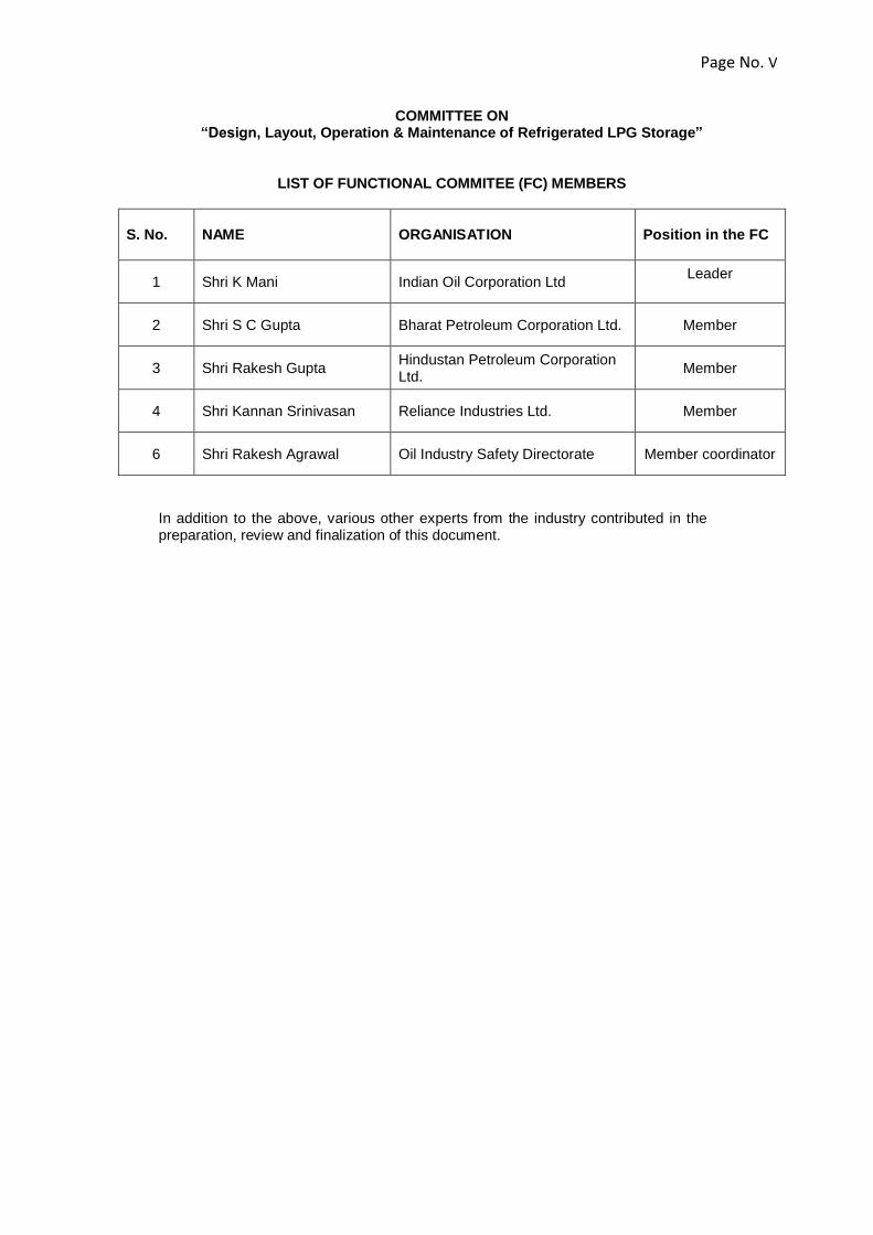
COMMITTEE ON
“Design, Layout, Operation & Maintenance of Refrigerated LPG Storage”
LIST OF FUNCTIONAL COMMITEE (FC) MEMBERS
S. No. NAME ORGANISATION
Position in the FC
1 Shri K Mani Indian Oil Corporation Ltd Leader
2 Shri S C Gupta Bharat Petroleum Corporation Ltd. Member
3 Shri Rakesh Gupta Hindustan Petroleum Corporation Ltd.
Member
4 Shri Kannan Srinivasan Reliance Industries Ltd. Member
6 Shri Rakesh Agrawal Oil Industry Safety Directorate Member coordinator
In addition to the above, various other experts from the industry contributed in the preparation, review and finalization of this document.

Page No. VI
CONTENTS
Sl. No. Description Page No.
1 INTRODUCTION
2 SCOPE
3 DEFINITIONS
4 REFRIGERATED LPG STOARGE AND HANDLING FACILITIES - PROCESS
5 TERMINAL LAYOUT
6 DESIGN CONSIDERATIONS REFRIGERATED STORAGE TANKS
7 FIRE PROTECTION, SAFETY AND EMERGENCY SYSTEMS
8 OPERATIONS OF REFRIGERATED LPG STORAGE INSTALLATION
9 INSPECTION & MAINTENANCE OF REFRIGERATED LPG STORAGE INSTALLATION
10 COMMISSIONING AND DECOMMISSIONING :
11 ANNEXURES
12 REFERENCES
“OISD hereby expressly disclaims any liability or responsibility for loss or damage resulting
from the use of OISD Standards/Guidelines.”
Draft OISD–STD–236 Page No. 1
Design, Layout, Operation & Maintenance of
Refrigerated LPG Storage
Design, Layout, Operation & Maintenance of Refrigerated LPG Storage 1.0 INTRODUCTION
Safety in Refrigerated LPG Storage facilities need specific attention considering the fact that large volumes of LPG are stored at near atmospheric pressure well below the ambient atmospheric temperatures. Any change in the ambient conditions of the product would result in boiling of large volume of liquid at a very high rate which may lead to rise in tank pressure and failure of storage tanks. These tanks are prone to collapse under vacuum in case of high rate of evacuation of product. The product stored in the tanks is without any odour. At present, there is no specific standard in the country for standardizing the design, Layout, Operation and Maintenance of the refrigerated LPG Storage Facilities. This standard is intended to serve as a guide to the Design, Layout, Operation & Maintenance of Refrigerated LPG Storage facilities. The primary objective of preparing this standard is to ensure safety in Refrigerated LPG Storage facilities by following the basic safety requirements and practices in the design, construction and Operation of Refrigerated Storage Facilities .
2.0 SCOPE
This standard lays down the minimum safety requirements for Design, Layout, Operation & Maintenance of Refrigerated LPG Storage facilities. The facilities at port and the associated cross country pipelines are not part of the scope of the present standard. This standard does not cover the buried / semi buried refrigerated LPG storage facilities. The requirements of OISD-STD-144 / 150 / 214 shall be applicable after the point LPG is no longer in Refrigerated State.
3.0 DEFINITIONS:
(1) Aboveground Tank or Aboveground Vessel: a tank or vessel all or part of which is exposed above grade.
(2) Auto-refrigeration: The chilling effect of vaporization of LPG when it is released or vented
to a lower pressure. (3) Annular Space: The space between the primary cylindrical liquid container and the
primary cylindrical product vapor container or cylindrical purge gas container of a double wall tank.
(4) Base Heating System: A heating system provided in the base slab or soil below the tank
system to prevent freezing of the soil and frost heave. (5) Base Slab: A continuous concrete base supporting the tank system. This base may be
either at grade or elevated and may be either supported by soil or piles. (6) Deriming: Synonymous with defrosting or de-icing refers to the removal, by heating and
evaporation, sublimation, or solution, of accumulated constituents that form solids, such as water, carbon dioxide, etc. from the low-temperature process equipment.
(7) Dyke: A structure remote from the tank system used to establish an impounding area for the purpose of containing any accidental spill of stored liquid. Sometimes this structure is referred to as a bund wall.

“OISD hereby expressly disclaims any liability or responsibility for loss or damage resulting
from the use of OISD Standards/Guidelines.”
Draft OISD–STD–236 Page No. 2
Design, Layout, Operation & Maintenance of
Refrigerated LPG Storage
(8) Elevated Foundation: A foundation with base slab, supported by either piles or piers located at an elevation above grade, leaving an air gap between the grade and the bottom of the base slab.
(9) Flameproof Enclosure: Type of protection in which the parts which can ignite an explosive
atmosphere are placed in an enclosure which can withstand the pressure developed during an internal explosion of an explosive mixture and which prevents the transmission of the explosion to the explosive atmosphere surrounding the enclosure.
(10) Frostbite: Frostbite is the medical condition where localized damage is caused to skin and other tissues due to freezing temperatures. Frostbite is likely to happen when human body comes in accidental contact with refrigerated LPG at subzero temperatures.
(11) Hazardous area: An area shall be deemed to be a hazardous area, where
(i) Petroleum having flash point below 65°C or any flammable gas or vapour in a concentration capable of ignition is likely to be present.
(ii) Petroleum or any flammable liquid having flash point above 65°C is likely to be refined, blended, handled or stored at or above its flash point.
(12) Hazardous Atmosphere: An atmosphere containing any flammable gas or vapour in a
concentration capable of ignition. (13) Levels and Volumes
Design Liquid Level: Maximum liquid level that will be experienced during operation of the tank. This is used for the static shell thickness determination. Maximum Liquid Capacity: The total volume between the design liquid level and the tank bottom. (This is also referred to as total liquid capacity in API 620.) Maximum Normal Operating Level: Maximum liquid level that will be experienced during normal operation of the tank. Minimum Normal Operating Level: Minimum liquid level that will be maintained during normal operation of the tank. The unusable volume of liquid below the minimum normal operating level is known as Heel. Net Working Capacity: The volume between the maximum normal operating level and minimum normal operating level.
Overfill Protection Margin: Capacity (tank height or volume) between the maximum normal operating level and the design liquid level
Seismic Freeboard: The design height above the maximum normal operating level to minimize or prevent overflow or damage to the roof due to sloshing of the liquid contents during a seismic event. Refer figure in Annexure A1 for details of Level and Volumes
(14) Liquefied Petroleum Gas (LPG or LP-Gas): The term applies to a mixture of certain light hydrocarbon predominately C3 & C4, derived
from petroleum & natural gas which are gaseous at ambient temperature and pressure,
may be condensed to a liquid state at normal ambient temperature by the application of
moderate pressure and conforming to IS : 4576 or IS: 14861.

“OISD hereby expressly disclaims any liability or responsibility for loss or damage resulting
from the use of OISD Standards/Guidelines.”
Draft OISD–STD–236 Page No. 3
Design, Layout, Operation & Maintenance of
Refrigerated LPG Storage
(15) Load Bearing Insulation: Insulation with special compressive strength properties used for thermal insulation and for transferring the load to the load bearing structure.
(16) Primary Liquid Container: Parts of a tank system that contain the liquid during normal
operation. (17) Primary Vapour Container: Parts of a tank system that contain the product vapour during
normal operation. (18) Pump Column: A pipe column to house a combined vertical pump and close coupled
electric motor. The column itself protrudes through the outer tank roof. (19) Secondary Liquid Container: Parts of a tank system that contain the liquid in the event of
leakage from the primary liquid container. (20) Process
Boil-Off: The process of vaporization of refrigerated product by heat conducted through the insulation surrounding the tank.
Design Pressure: The maximum gauge pressure permissible in the vapour space above the product of a tank system in its design condition.
Rollover: The spontaneous and sudden uncontrolled movement of a large mass of liquid from the bottom to the top surface of a refrigerated storage vessel due to an instability caused by an adverse density gradient due to presence of stratified liquids of different densities. Rollover can cause a sudden pressure increase and can affect vessel integrity.
Set Pressure: The gauge pressure at which the pressure relief device first opens.
Set Vacuum: The gauge pressure at which the vacuum relief device first opens. Sweetening : Introduction of LPG vapour into the tank
(21) Purging: The replacement of one gas/vapour by another in an enclosed tank system by displacement, by dilution, by diffusion or by combinations of these actions.
(22) Shall: Indicates provisions that are mandatory; (23) Should: Indicates provisions that are recommended but not mandatory; (24) Storage Concepts
Double Containment (double integrity) Tank System A double containment system is one having a double tank designed so that both the inner tank and the outer tank are capable of independently containing the refrigerated liquid stored. The inner tank contains the refrigerated liquid under normal operating conditions. The outer tank is intended to contain the refrigerated liquid product leakage from the inner tank. The outer tank is not designed to contain product vapour in the event of liquid leakage from the inner tank. Full Containment Tank System A full containment storage tank is one meeting all the requirements of double containment storage plus the additional requirement of that it shall avoid the uncontrolled release of

“OISD hereby expressly disclaims any liability or responsibility for loss or damage resulting
from the use of OISD Standards/Guidelines.”
Draft OISD–STD–236 Page No. 4
Design, Layout, Operation & Maintenance of
Refrigerated LPG Storage
product vapour in the event of liquid leakage from the inner tank. The outer tank shall always contain the vapour during normal operation. Refrigerated Tank System Storage in a vessel or tank artificially maintained at a temperature below the nominal ambient temperature. This includes the combination of a primary liquid container, together with secondary liquid container (if any), insulation, vapor container, appurtenances, instrumentation and all other associated elements. The product is stored at their respective boiling point depending upon the constitution at near atmospheric pressure. Single containment A single containment system is one having either a single tank or a tank comprising an inner tank and an outer container designed and constructed so that only the inner tank is required to meet the low temperature ductility requirements for storage of that product. The outer container of a single containment storage tank would primarily be for retention and protection of insulating material and to contain the vapour gas pressure, and would not be designed to contain liquid in the event of leakage from the inner tank.
(25) Stratification: When liquids of different densities are received in the same tank, there is a possibility that layers are created with a less dense liquid overlaying a heavier one. This is called stratification. Unstable stratification may also occur when the liquid in the lower layer becomes less dense due to heat input, while the liquid in the upper layer becomes heavier due to the evaporation at the surface. This unstable situation can relieve itself with a sudden /spontaneous rapid mixing process (Roll over) which occurs in tanks as a result of a density inversion.
“OISD hereby expressly disclaims any liability or responsibility for loss or damage resulting
from the use of OISD Standards/Guidelines.”
Draft OISD–STD–236 Page No. 5
Design, Layout, Operation & Maintenance of
Refrigerated LPG Storage
4.0 REFRIGERATED LPG STORAGE AND HANDLING FACILITIES - PROCESS Refrigerated LPG: The product stored either in pure propane & pure butane form or in premixed LPG (i.e. mix of propane & butane conforming to IS: 4576) at their respective boiling point at near atmospheric pressure. Receipt of refrigerated LPG, butane or propane. The refrigerated propane, butane or LPG is discharged by the pumps of the ocean tanker through the unloading arms at the port to the cross country pipelines and is transferred to the designated storage vessels at the terminal through insulated pipelines. Storage of Refrigerated LPG:
The primary function of storage vessel is to receive, hold and stock refrigerated product. Above ground dome roof tanks are used to store the liquefied gas at or below its boiling point. The tank is designed to ensure the following functions:
Liquid Retention The storage tank shall be capable of withstanding the hydrostatic load of the liquid and low temperature of the propane, Butane and /or LPG. Gas Tightness Tanks should be tight enough to prevent any evaporation losses and also to avoid ingress of air and moisture. Thermal Insulation Thermal insulation shall be provided to: Limit boil-off rates Avoid cold spots on the outer shell. Thermal Stresses Under normal operating conditions, the tank is subjected to variation in the temperatures. Also during start up, tank temperature is required to be brought down from ambient to refrigerated temperatures. Sometimes the tank may require deriming for various reasons like repair of internals, modifications etc. Hence, the tanks shall be capable of withstanding the heat variation.
The detailed requirements of Refrigerated Storage Tanks has been detailed in section 5
REFRIGERATION SYSTEM: BOIL OF COMPRESSORS, FLASH COMPRESSORS, CHILLERS/ CONDENSERS:
An auto-refrigeration system comprising of positive displacement compressors, LPG condenser and liquid receiver is provided to maintain refrigerated LPG tank pressure. The auto-refrigeration system compensates for heat gain in the tank, headers and in-tank pump heat. Large capacity refrigeration compressors called Flash Compressors are operated to handle large-scale refrigeration requirement during ocean tanker receipts and smaller capacity refrigeration compressors called Boil-Off Compressors are used during normal course of operations to maintain tank temperatures at required levels.

“OISD hereby expressly disclaims any liability or responsibility for loss or damage resulting
from the use of OISD Standards/Guidelines.”
Draft OISD–STD–236 Page No. 6
Design, Layout, Operation & Maintenance of
Refrigerated LPG Storage
The vapor thus extracted is compressed and then re-liquefied by condensing in condensers / chillers. The condensate, intermediately stored in condensate receivers, is then pumped to separate buffer storage tanks thereby completing an open-cycle auto-refrigeration process. The liquid returned to the either refrigerated storage tank or above ground tank as per the designed process flow. Refrigerated storage tanks and refrigeration systems are designed to maintain normal process operations during routine maintenance of equipment, and to assure plant safety under emergency conditions. Sufficient sparing of equipment is provided so that any single piece of equipment can be removed from service while maintaining normal operations. The terminal shall be provided with flare system to enhance the plant safety. The flaring is done only as a final solution when the normal Boil / Flash compressor are not available able to meet the requirement. Flare is connected to the tank pressure vent valve to provide sufficient time for operator intervention in case of pressure rise. Product withdrawal The product stored in the tanks is pumped out using In tank Pumps (duty and standby) installed inside each tank. Heating / Blending: The refrigerated product (LPG/propane/ butane) is brought to ambient condition from its sub-zero temperature by various method of heating the product by either through steam / heat exchangers / air preheaters etc. It is very important to ensure that the product LPG / propane / butane at downstream of heating arrangement shall be at temperature above 15°C. The failure of the heating arrangement to increase the temperature of the product upto 15°C should immediately trip the intank pump and prevent flow of refrigerated product from heating arrangement. The product (propane & butane) at normal temperature above 15°C is blended in a blending unit in the correct ratio to make commercial LPG. The final product is dozed with ethyl mercaptan from the dozing facilities for odorizing LPG in the correct proportion. Beyond this point provision of OISD-144/150 shall be applicable. The pipings/equipments at the downstream of the heating arrangement upto the next storage vessel or despatch / loading end shall be of LTCS material only.
“OISD hereby expressly disclaims any liability or responsibility for loss or damage resulting
from the use of OISD Standards/Guidelines.”
Draft OISD–STD–236 Page No. 7
Design, Layout, Operation & Maintenance of
Refrigerated LPG Storage
5.0 Terminal Layout: Philosophy: Terminal lay out philosophy shall consider location of the facilities at a site of suitable size, topography and configuration with a view to minimise the hazards to persons and property due to leaks and spills of LPG. Before selecting a site, all site related characteristics which could affect the integrity and security of the facility shall be determined. A site shall provide ease of access so that personnel, equipment, materials from offsite locations can reach the site for fire fighting or controlling spill associated hazards or for the evacuation of the personnel. OISD–STD-118 covers the layout consideration for the Oil and Gas Installations. The above standard is generally applicable for consideration of layout of Refrigerated LPG Terminal. The Control Room shall be constructed as per OISD-STD-163.The minimum distance of 60 m shall be maintained between LPG Storage Tank and Substation. Specific points related to Refrigerated LPG are brought out here. Basic Information Information on following items should be collected before proceeding with the development of overall plot plan.
A:
- Site location map - Site Geotechnical and Seismic data. - Soil characteristics - Prevailing wind speed and direction over a period - Meteorological data including corrosive characteristics of the air and frequency of lightening - Area topography contour map - High flood level in the area and worst flood occurrence. - Storm water disposal point and effluent disposal point - Source of water supply and likely entry / exit point - Electric supply source and direction of entry point - LPG entry point/ Gas exit point - Approach roads to main Terminal areas - Surrounding risks - Air routes and the proximity of the Airports. - Fire station - The Proximity to the unloading jetty.
B:
- Terminal capacity- - Process flow diagram indicating flow sequence - Process units and capacities - Refrigerated LPG storage tanks, sizes and type of storage tanks - Other LPG storage tanks - LPG transfer - No. of flares - Provision for spill containment and leak control - Minimum inter distances between facilities as well as between facilities & boundaries - Operating and maintenance philosophy for grouping of utilities - Plant and non-plant buildings - Space for future Expansion - Chemical storage - Ware house and open storage areas.
“OISD hereby expressly disclaims any liability or responsibility for loss or damage resulting
from the use of OISD Standards/Guidelines.”
Draft OISD–STD–236 Page No. 8
Design, Layout, Operation & Maintenance of
Refrigerated LPG Storage
Grouping: The Refrigerated LPG Terminal may consist of the following basic facilities. - Refrigerated LPG receipt line to shore terminal. - Refrigerated LPG Storage - Pressurized LPG storage facilities. - Boil Off / Flash Compressor, condensers, chillers, - Process Area - Heating / Blending / dozing facilities. - Flare system - Utility Block (Air Compressors, De-mineralization plant, Boiler Room etc.) - Fire water Storage and fire water Pump House. - LPG loading/ transfer facilities Road / Rail / Pipeline - Control Room - Administrative Block - Workshop - Warehouse - Electrical Substation. - Laboratory General Considerations - Future expansion requirement shall be assessed and provision of space for the same should be
made. - The Erection and Maintenance requirements shall be considered. - The layout of the facilities including the arrangement and location of plant roads, walkways, doors
and operating equipment shall be designed to permit personnel and equipment to reach any area effected by fire rapidly and effectively.
- The layout shall permit access from at least two directions. - Each group shall be separated by roads on all four sides for easy access and emergency
handling. - Classification of areas for Electrical Installations in LPG Terminal shall be as per OISD-STD-113
as applicable. Processing Equipment Spacing: The table II of OISD-STD-118 shall be applicable for process equipment. Aboveground Refrigerated LP-Gas Containers - The minimum horizontal distance between the shell of a refrigerated LPG tank and the line of
adjoining property that may be developed shall be 60 m. Where residences, public buildings, places of assembly, or industrial sites are located on adjacent property, greater distances or other supplemental protection shall be evaluated.
- Non refrigerated LP-Gas containers or flammable liquid tanks shall not be located within dykes or
impoundments enclosing refrigerated LP-Gas containers. - Refrigerated LP-Gas containers shall not be installed one above the other. - The minimum distance between aboveground refrigerated LP-Gas containers shall be one-half
the diameter of the larger container. - The minimum horizontal distance between the shell of a refrigerated LPG tank and the shell of
another non-refrigerated hydrocarbon storage facility shall be the largest of the following distances subject to a max of 60 m.

“OISD hereby expressly disclaims any liability or responsibility for loss or damage resulting
from the use of OISD Standards/Guidelines.”
Draft OISD–STD–236 Page No. 9
Design, Layout, Operation & Maintenance of
Refrigerated LPG Storage
i. If the other storage is pressurized, three quarters of the larger tank diameter. or 30 m
whichever is more. ii. If the other storage is in atmospheric tanks and is designed to contain material with a
flash point of 55 or less, one diameter of the larger tank or 30 m whichever is more iii. If the other storage is in atmospheric tanks and is designed to-contain material with a
flash-point greater than 55 C, half the diameter of the larger tank or 30 m whichever is more.
- Refrigerated LPG tanks shall not be located within buildings, within the spill containment areas of other flammable or combustible liquid storage tanks or within the spill containment areas of pressurized storage tanks.
- The inter-distance requirements among various process facilities such as flash / boil off
compressor area heat exchanger / condensors / blending / dosing facilities shall be governed by process / design / hazop considerations.
There shall not be any process facility such as condenser / compressor house / dosing / blenders within 30 m of tank shell. The inter-distance for the facilities handling non refrigerated LPG shall be as per OISD-144/150/214 for respective facilities.
Spill Containment a. Single containment Refrigerated LPG tanks shall be provided with spill containment facilities. Spill
containment shall be provided by the dyking of the area surrounding the vessel.
b. For double and full containment tanks, only kerb wall of atleast 0.6 m height shall be provided. The distance of kerb wall from tank shell shall not be less 15 m. In this case, double wall tanks shall be designed to hold the entire quantity in the outer shell as well as suitable to handle hydrostatic pressure and low temperature requirements.
c. To prevent the accumulation of flammable material under or near a refrigerated LPG tank, the ground under and surrounding the tank shall be graded to drain any spills to a safe area away from the tank.
d. Diking:
(i) If diking around the vessel is to be used for spill containment, the dyked area shall be designed to meet the capacity of single largest tank in the dyke. Effective containment capacity shall be after considering 0.2 m of free board.
(ii) The grading of the area under and surrounding the vessel shall direct any leaks or spills to the
edge of the dyked area. The grading shall be a minimum of 1% slope. Within the dyked area, the grading shall cause spills to accumulate away from the vessel and any piping located within the dyked area.
(iii) Each refrigerated LPG tank shall be provided with its own dyked area. The holdup of the
dyked area shall be at least 100% of the volume of the tank.
(iv) More than one tank may be enclosed within the same dyked area provided provisions are made to prevent low temperature exposure resulting from leakage from any one tank from causing subsequent leakage from any other tank. When dykes are used as part of the spill containment system, the minimum height shall be 0.5 m, measured from the inside of the dyked area. Where dykes are higher than 1.8 m, provisions shall be made for normal and emergency access into and out of the dyked enclosure. The height of dyke shall not exceed

“OISD hereby expressly disclaims any liability or responsibility for loss or damage resulting
from the use of OISD Standards/Guidelines.”
Draft OISD–STD–236 Page No. 10
Design, Layout, Operation & Maintenance of
Refrigerated LPG Storage
2.0 m excluding free board of 0.2 m
e. The edge of a dyke/ kerb wall , impoundment, or drainage system that is intended for a refrigerated LP-Gas container shall be 30 m or more from a property line that can be built upon, a public way, or a navigable waterway.
f. The ground within 7.5 m of any aboveground refrigerated LP-Gas container and all ground within a dyke, impoundment, or drainage area shall be kept clear of readily ignitable materials such as weeds and long, dry grass.
Marking of Tanks Each refrigerated storage system shall be identified by the attachment of name plates readily visible and accessible which shall give the following details: - Manufacturers name and serial number - Design standard - Maximum LPG filling level - Liquid volume of the tank when filled with LPG to the maximum safe level - Maximum and minimum design pressure - Maximum and minimum design temperature - Density of the LPG for which the tank is designed - Year of construction and test Piping, Valves and Equipment: a. Piping, valves and equipment for handling refrigerated LPG shall confirm to the low temperature requirements and to be suitable for use at the temperature of the application and shall be designed for not less than the maximum pressure and for minimum temperature to which they may be subjected. b. Cast iron shall not be used for piping systems handling refrigerated LPG c. Screwed joints and compression fittings shall not be used in piping for low temperature Propane, Butane or LPG service , except for the instrument lines downstream of an isolation valve. d. All the welds of Propane, Butane or LPG service line shall be 100% radiographed and retained for future references. e. Piping systems and their supports shall be suitably insulated / protected for fire exposure conditions.

“OISD hereby expressly disclaims any liability or responsibility for loss or damage resulting
from the use of OISD Standards/Guidelines.”
Draft OISD–STD–236 Page No. 11
Design, Layout, Operation & Maintenance of
Refrigerated LPG Storage
6.0 DESIGN CONSIDERATIONS REFRIGERATED STORAGE TANKS
Design Information: Following information shall be collected at the design stage:
- Natural environmental loads (such as earthquake, wind), - Spillage handling requirements, - Corrosion allowances, - Hazard Protection System requirements (such as water spray, gas detection, if any); - Accidental loads determined by assessment of risk (such as fire, pressure wave, projectile impact, if
any); - Settlement prediction and inspection method; - Ambient temperature
- Properties of the stored product, including density at the design temperature, - Minimum design temperature of primary containment, - Tank maximum liquid capacity; - Design liquid level; - Internal diameter and height of inner tank - Normal maximum/minimum operating liquid level; - Design pressure/vacuum, maximum/minimum operating pressure, - Pressure relief and vacuum set points.(High/low pressure alarm set point,) - High/low level alarm. - Minimum normal operating level basis, - Overfill protection margin, - Capacity to receive the interface turbulance of two products at different temperature and density. - Product filling/emptying rates, - Rollover applicability and rollover prevention provisions, - Design boil-off rate, - Condensation of vapours in annular space.
- Risk assessment, - Applicable codes and standards; - Materials of tank construction; - Emergency relief valve discharge flow rate - Piping and instrumentation requirements, - NDE applied to non-hydrostatically tested components; - Tank type, - Networking capacity, - Tank location on plot plan, - Process flow diagrams, piping & instrumentation diagrams (P&IDS) - Pre-commissioning and commissioning procedures, including purging, drying, and cool down; DESIGN REQUIREMENTS Tank Systems for Refrigerated Storage
This section covers low pressure, aboveground, vertical, and cylindrical tank systems storing liquefied gases requiring refrigeration. These are general requirements on selection of storage concept, performance criteria, accessories/appurtenances, quality assurance, insulation, and commissioning of tank systems.
The Refrigerated storage tank system consist of a primary liquid and vapor containment constructed of metal, concrete, or a metal/concrete combination and, when required, a secondary liquid containment.

“OISD hereby expressly disclaims any liability or responsibility for loss or damage resulting
from the use of OISD Standards/Guidelines.”
Draft OISD–STD–236 Page No. 12
Design, Layout, Operation & Maintenance of
Refrigerated LPG Storage
Metallic Containers
Metallic container materials, design, fabrication, inspection, examination, and testing shall be in
accordance with API 620 including Appendix R.
Concrete Containers
Concrete container materials, design, construction, inspection, examination, and testing shall be in
accordance with ACI 376.
General Requirements:
For all containment systems, liquid-tightness of the primary liquid container is required. Liquid is not
permitted
to accumulate outside the primary liquid container during normal operation. Tank systems where this is
not assured would require consideration of issues such as liquid collection and disposal, potential cold
spots, effect on tank venting, etc.
Type:
Three main different storage concepts are :
Single containment Double Containment Tank System Full Containment Tank System Single containment A single containment system is one having either a single tank or a tank comprising an inner tank and an outer container designed and constructed so that only the inner tank is required to meet the low temperature ductility requirements for storage of that product. The outer container of a single containment storage tank would primarily be for retention and protection of insulating material and to contain the vapour gas pressure, and would not be designed to contain liquid in the event of leakage from the inner tank. Double Containment (double integrity) Tank System A double containment system is one having a double tank designed so that both the inner tank and the outer tank are capable of independently containing the refrigerated liquid stored. The inner tank contains the refrigerated liquid under normal operating conditions. The outer tank is intended to contain the refrigerated liquid product leakage from the inner tank. The outer tank is not designed to contain product vapour in the event of liquid leakage from the inner tank. Full Containment Tank System A full containment storage tank is one meeting all the requirements of double containment storage plus the additional requirement of that it shall avoid the uncontrolled release of product vapour in the event of liquid leakage from the inner tank. The full containment concept evolved from double containment and has the following advantages: Controls or prevents the release of product vapors following primary liquid container leakage or failure; Greater ability to resist external threats such as blast, fire and impact compared to single and double containment tanks.
“OISD hereby expressly disclaims any liability or responsibility for loss or damage resulting
from the use of OISD Standards/Guidelines.”
Draft OISD–STD–236 Page No. 13
Design, Layout, Operation & Maintenance of
Refrigerated LPG Storage
Guidance on selection of storage concept: The selection is to be based on a risk assessment. The risk is a function of not only the storage concept itself but also the way the tank system relates to many other aspects of the overall facility. Therefore other aspects of the facility and its surroundings shall be considered.
Plans for the proposed facility should specifically address the impact of vapour clouds and radiant heat
flux on plant facilities and adjacent properties. Intrinsic within this approach is the selection of storage
concept; separation distances and proximity to property lines; site topography; soil conditions; and ground
water conditions. A review of the site may identify constraints or provide opportunities to utilize specific
features of site to the benefit of the facility.
The rate of heat generation from a large pool of burning liquefied gas is significantly higher than that of a similar pool of another oil product. In order to limit the radiant heat flux on the surroundings to acceptable levels it may be necessary to reduce as much as possible the area of the pool of spilled liquefied gas though the selection of containment concept. External hazards include the following:
- Environmental hazards including earthquake, lightning, wind loading including hurricane/typhoons,
flooding,
- Snow and ice loading, tsunamis;
- Ground conditions, weak strata, liquefiable layers, lateral spreading, and presence of caverns, voids
and defects;
- Flying objects, and equipment following a process incident;
- Pressure waves due to vapor cloud ignitions from the process plant, adjacent plant, process
equipment, and Carriers including facilities located outside the boundary limits;
- Operational and upset conditions including spillage and leakage of product;
- Maintenance hazards;
- Fire hazards from adjacent tanks, dykes, relief valves, sumps, jet fires, and plant areas;
- Proximity of tanks to external uncontrolled sources of ignition such as ground flares, flares.
Internal hazards include the following:
- Leakage of product from the inner tank;
- Overfilling of the tank;
- Over/under pressurization of the tank due to process upset;
- Rollover leading to over pressurization of the tank;
- Major leak (i.e. The complete failure of the inner tank);
- Minor leak (i.e. Partial leakage from the inner tank due to a postulated defect);
- Fatigue and cyclic loading of key components (e.g., annular plates);
- Corrosion;
- Failure of pipe work attached to the tank bottom/sides;
- Instrumentation failures.
Safety Improvement
If the assessment of risk identifies risks that exceed acceptable limits, then positive measures (action)
should be taken to reduce the level of risk to an acceptable level. Typical mitigation measures may be as
follows:
“OISD hereby expressly disclaims any liability or responsibility for loss or damage resulting
from the use of OISD Standards/Guidelines.”
Draft OISD–STD–236 Page No. 14
Design, Layout, Operation & Maintenance of
Refrigerated LPG Storage
- Selection of alternative containment concepts (i.e. Migration from single containment to double or full
containment);
- Improvements to process equipment selection;
- Substitution of a metal roof on a full containment tank with a concrete roof;
- Increase in safety distances (separation distances) to limit impact in respect of vapor dispersion and
radiant heat flux;
- Elimination of ignition sources;
- Selection of alternate layouts and site locations;
- Inclusion of protection systems to shield/protect critical equipment from hazard.
General Design Considerations: - All pipe connections shall be through the top of the tank to avoid siphoning effect. All isolation valves
shall be pneumatically operated and interlocked to prevent accidental movement of tank contents from one tank to another.
- Each tank shall be provided with at least two independent means of determining the liquid level. The same shall be provided with isolation arrangement so that they can be replaced/ repaired without taking the tank out of service
- Additionally each tank shall be provided with high level alarm and a high level trip system which shall be designed to stop all liquid flows into the tank to prevent over-filling.
- The high level trip system shall be independent of both high level alarm and of liquid level gauges.
- Double and full containment system shall be provided with means for detecting and removing the liquid leakage / buildup of condensation in the annular space. The provision made for injecting nitrogen for purging is considered meeting the requirement. Vapor at higher temperatures may be pushed for vaporizing the condensate thru this provision.
- All the primary containers shall be tested to the maximum filling level with water.
- Outer tanks of double and full containment system shall be tested as above. To prevent damage to the inner shell the level in the inner tank shall be maintained above the level in the outer shell during the hydrostatic test.
- The tank has a spray-ring for cool-down with product and skin mounted temperature elements at Tank Shell to monitor the cool-down during commissioning. Temperature element is also required to be provided at Tank bottom at different radii in uniformly distributed manner to avoid temperature stratification during commissioning.
- If the tank is resting for a longer period, a potential for temperature stratification could exist. Warmer liquid from the tank bottom is moved upwards during restarting which could lead to excessive evaporation and higher tank pressure. Mean, such as the recirculation should be provided to break the stratification.
- Tank shall be provided with pressure/vacuum relief valves as per API standard 2000 independent of the pressure/vacuum control and trip systems.
- Sections of LPG pipe-work that could be blocked are provided with thermal relief valves.
- 100% capacity In-tank pumps (duty and standby) shall be provided for delivery of product from the refrigerated storage tank. An additional separate pump well and foot valve shall be provided in each refrigerated tank.

“OISD hereby expressly disclaims any liability or responsibility for loss or damage resulting
from the use of OISD Standards/Guidelines.”
Draft OISD–STD–236 Page No. 15
Design, Layout, Operation & Maintenance of
Refrigerated LPG Storage
Design Pressure The design pressure of a refrigerated LPG tank is determined by the product's vapor pressure at the -storage temperature. The set pressure of the pressure-relieving device shall be at least 5% greater than the design operating pressure. The tank section above the maximum liquid level shall be designed for a pressure of at least that at which the pressure relief valves are to be set and for the maximum partial vacuum that can be developed. All portions of the tank below the maximum liquid level shall be designed for at least the most severe combination of gas pressure (or partial vacuum) and static liquid head affecting each element of the tank. Design Temperature The design temperature for a refrigerated-LPG tank shall be the lowest of the following: - The lowest temperature to which the tank contents will be refrigerated. - The lowest shell temperature resulting from cold ambient conditions, if that temperature is below the
refrigerated product temperature. - The auto refrigeration temperature of the contents. Pressure / Vacuum Control and Relief Systems: The purpose of the pressure relief system is to prevent the Tanks from excess pressure beyond design by way of controlled release of hydrocarbon vapour to the atmosphere. The purpose of the vacuum control system is to prevent the Tanks from implosion under vacuum beyond design by way of controlled breathing of air from atmosphere into the tank. All the tanks shall be provided with a pressure / vacuum control and relief system to maintain the Tank pressure within the design pressure range in all conditions. Vapour are generated by:
- Liquid entering the tank. - System heat in–leak - Energy input from Intank Pumps. - Decrease in atmospheric pressure. - Mixing of Product of different constituents.
In normal operation such vapours shall be collected by the Boil Off / Flash compressors and the same is re-liquefied thus preventing their loss to the atmosphere. The terminal shall be provided with flare system to relieve the excess pressure, when the normal Boil / Flash compressor are not available / able to meet the requirement. Flare is connected to the tank pressure vent valve to provide sufficient time for operator intervention in case of pressure rise. Low pressures shall be limited by the use of following systems: - Tripping of Boil off / Flash compressors and product transfer pumps. - The supply of hot gas or liquid or inert gas into the tank. - The relief system shall be such that it is able to function even at time when the control system is failed. The mixing of air with flammable LPG vapours is undesirable and only acceptable when an alternate (implosion leading to potential tank failure) would constitute a greater hazard. Pressure / Vacuum-Relieving Devices

“OISD hereby expressly disclaims any liability or responsibility for loss or damage resulting
from the use of OISD Standards/Guidelines.”
Draft OISD–STD–236 Page No. 16
Design, Layout, Operation & Maintenance of
Refrigerated LPG Storage
- Relief Valves shall be provided for tanks designed to conform to API Std 620 R in accordance with
API Std 2000.
- The pressure relief valves should be adequate to relieve the worst case emergency flow, assuming all other outlets from the tanks including that of flare are closed.
- When a closed inner-tank design is used with an outer vapor-tight shell, the outer shell shall be equipped with one or more pressure/vacuum-relieving devices.
- Each refrigerated LPG tank shall be provided with at least one pressure-relieving device set to discharge at no more than the maximum allowable working pressure of the tank.
- Tanks that may be damaged by internal vacuum shall be provided with at least one vacuum-relieving device set to open at not less than the partial vacuum design pressure.
Factors for consideration for sizing of pressure relief valves: - Liquid entering the tank at maximum rate. - Maximum possible boil off assuming failure of boil off compressor. - Effect of radiation from an adjacent fire (tank) - Effect of possible hot product intake in the tank. - Flow of hot liquid / vapour in the tank assuming failure of vacuum protection system. - Effect of possible mixing of products
Product Mixing
Loading LPG into a partially full refrigerated LPG tank where LPG being loaded has a different composition than the existing tank content can cause generation of huge quantities of vapor. If this condition can exist, the vaporization rate can be calculated and included in the sizing of the tank pressure relief valves. As a minimum, the pressure relief valves shall be sized to discharge vapor in case of refrigeration system failure to maintain the refrigerated storage tank pressure within the design limits for at least 24 hrs.
Factor for consideration for sizing of vacuum relief valves: - Maximum possible liquid withdrawal rate. - Maximum possible vapour withdrawal rate (assuming the compressors fail to trip)
The pressure and vacuum relief valves must be provided with block valves with spare positions and interlocks so that inspection / maintenance can be done without opening the tank to atmosphere and without reducing the relief capacity below the design requirements. Emergency relief valves shall discharge directly to the atmosphere. Precautions must be taken to prevent icing on relief valves. Care must be taken to ensure prevention of possibility of freezing up of vent / flare system. Care must be taken to ensure prevention of possibility of blockage due to liquid in lines of vent / flare system. Therefore such lines should be free of pockets and slope towards a knock out drum. THERMAL CONSIDERATIONS The tank foundation shall be designed to prevent 0°C (32°F) or lower temperatures from penetrating the pad and soil. This limitation shall be accomplished by ventilation, insulation, heating systems, or a combination of these. Heating elements, controls, and temperature sensors shall be designed for easy access and replacement while the tank is in service. Foundation heating systems shall be provided with

“OISD hereby expressly disclaims any liability or responsibility for loss or damage resulting
from the use of OISD Standards/Guidelines.”
Draft OISD–STD–236 Page No. 17
Design, Layout, Operation & Maintenance of
Refrigerated LPG Storage
temperature monitoring and controls. The design of the supporting structure shall consider loads resulting from (a) the thermal gradient across the supporting structure, foundation, and piling due to the temperature of the contents of the vessel and (b) the thermal shock from accidental spills. Insulation - The tanks external insulation and cladding shall:
- Be weatherproof and capable of withstanding direct impingement of the cooling water from any fixed
deluge system. - Be impervious to the ingress of moisture. The insulation shall comprise or contain a vapor barrier
shall be weatherproofed. - Insulation and weatherproofing to be fire retardant. Steel surfaces covered by insulation to be
properly coated to prevent corrosion. TANK ACCESSORIES Temperature Indicators/ Level Indicators / Pressure Indicators Each tank shall be fitted with thermocouples or equivalent temperature indicating devices for use during cooldown and operations. Temperature Element shall be provided in skin at uniform interval of the tank shell at different heights for correct representation of temperature of product inside. Temperature element is also required to be provided at Tank bottom at different radii in uniformly distributed manner to avoid temperature stratification during commissioning. Level Indicators - Each tank shall be provided with at least two independent means of determining the liquid level. The
same shall be provided with isolation arrangement so that they can be replaced/ repaired without taking the tank out of service
- Additionally each tank shall be provided with high level alarm and a high level trip system which shall be designed to stop all liquid flows into the tank to prevent over-filling. The high level trip system shall be independent of both high level alarm and of liquid level gauges.
- Double containment and full containment system shall be provided with means for detecting and
removing the liquid leakage in the annular space Pressure Indicators Each tank shall be provided with at least two Pressure Gauges/Transmitters. The same shall be provided with isolation arrangement so that they can be replaced/ repaired without taking the tank out of service. Pressure indicators shall also be provided with local display. Sampling Connections If sampling connections are required, they shall be installed on the tank piping rather than on the tank. Tank Accessory Materials - All materials including non-metallic parts of valves, seals, gaskets, etc shall be resistant to LPG under
the service conditions of pressure and temperature to which they will be subjected.
- Low-ductility materials such as cast iron shall not be used.
“OISD hereby expressly disclaims any liability or responsibility for loss or damage resulting
from the use of OISD Standards/Guidelines.”
Draft OISD–STD–236 Page No. 18
Design, Layout, Operation & Maintenance of
Refrigerated LPG Storage
- Except for instrument lines downstream of an isolation valve, screwed joints and compression fittings shall not be used in piping for low temperature service.
PIPING REQUIREMENTS - Piping for refrigerated product shall conform to the low temperature requirements of ASME B31.3 or
equivalent.
- All the piping welds shall be 100 % radiographed. The same shall be preserved for future reference. - Location: When cold piping is routed below grade, trenches, casing, other means shall be used to
permit expansion and contract of the piping.
- Multiple Product Types: When a storage facility handles more than one type of product, dedicated loading and unloading lines between tanks and racks shall be considered for each type of product.
Thermal pressure relief: - Any sections of pipelines in which LPG may get trapped e.g. between shut off valves, shall be
protected against excessive pressure caused by thermal expansion of the liquid contents by thermal pressure relief valves.
- The settings shall of thermal pressure relief valves shall not be less than the maximum working pressure of the line and shall not be more than the design pressure of the pipe line.
- If the relief valves discharge to atmosphere the discharge must be arranged in a safe manner. Valves Shutoff valves and accessory equipment shall be of material suitable for the operating pressure and temperature extremes to which they may be subjected. REFRIGERATION SYSTEM LPG Temperature The refrigeration system shall maintain the product (Commercial Propane, butane and /or LPG) at a tem-perature at which the LPG's vapor pressure does not exceed the tank's design pressure. Sizing The sizing of the refrigeration system shall consider the following factors: Heat flow from the following sources:
- The difference between the design ambient temperature and the design storage temperature.
- Maximum solar radiation.
- Receipt of product that is warmer than the design temperature, if such an operation is expected.
- Foundation heaters, connected piping.
- Vapor displacement during filling and vapor return during product transfer. Pressure-Relieving Devices

“OISD hereby expressly disclaims any liability or responsibility for loss or damage resulting
from the use of OISD Standards/Guidelines.”
Draft OISD–STD–236 Page No. 19
Design, Layout, Operation & Maintenance of
Refrigerated LPG Storage
The system shall be in line with the design code of the refrigerated storage. Refer to API 2000 & API RP 520, Parts I and II, for the proper design of pressure-relieving devices and systems for process equipment used in liquefaction and vaporization facilities.

“OISD hereby expressly disclaims any liability or responsibility for loss or damage resulting
from the use of OISD Standards/Guidelines.”
Draft OISD–STD–236 Page No. 20
Design, Layout, Operation & Maintenance of
Refrigerated LPG Storage
7.0 FIRE PROTECTION, SAFETY AND EMERGENCY SYSTEMS
GENERAL The concept of loss control shall be based on the philosophy that an incident of loss of containment of LPG should not escalate to the extent that facilities are endangered and the public at large is subjected to an unacceptable risk. Reasonable and reliable safeguards for the protection of properties, personnel and surroundings from damages resulting from fires, explosions and other unsafe conditions in a Refrigerated LPG Storage Facility shall be provided so as to accomplish the following objectives considering both normal and abnormal conditions:
Limit or prevent escalation of a fire by providing spacing that adequately separates the Storage, transfer, loading and unloading equipment, buildings, utility etc.
Minimize or avoid serious injury to personnel by providing adequate means of escape to evacuate safely, access for emergency responders and safe access for personnel to isolate plant and equipment.
Contain and prevent the spread of fire by having early detection and warning devices that enable emergency isolation, shutdown and depressurization of vessels/equipment remotely to limit the volume of flammable material released in the event of a fire.
Refrigerated tanks and their associated dykes and impounding basin should be such that in the event of either a tank fire or a spill fire, thermal radiation levels do not exceed the maximum limits in the table below (IP 1987): In any case minimum Inter-distance spacing as per table 2 of OISD Std. 118 & chapter 5.0 of the present standard shall be observed.
Sl Nos
Site Maximum Thermal Flux ( kW/m2)
1 Outer surfaces of adjacent refrigerated tanks - Thermally protected(1)
- Unprotected(2)
32 8
2 Outer surfaces of adjacent tanks having flammable products -Thermally protected(1)
-Unprotected(2)
32 8
3 Outer surfaces of adjacent LPG pressure vessels/ process equipment(3)
8
4 Personnel inside boundary -Process Area (4)
-Protected work area(5) -Work area (6)
8 8 5
5 Plant Boundary
-Critical area(7) -Urban Area(8)
-Remote area ( 9)
1.5 5
13
Notes (1) Protection by water sprays, insulation , radiation screens (2) Protection by spacing alone (3) Allowable radiation flux restricted due to longer duration of exposure resulting from a refrigerated tank /bund fire. (4) Trained plant personnel familiar with escape routes and temporary shelter locations in plant (5) Permanent building where personnel are shielded (6) Temporary building without shielded means of escape (7) Unshielded area with people present during emergencies (8) Neither a remote or critical area (9) Infrequently occupied by people
“OISD hereby expressly disclaims any liability or responsibility for loss or damage resulting
from the use of OISD Standards/Guidelines.”
Draft OISD–STD–236 Page No. 21
Design, Layout, Operation & Maintenance of
Refrigerated LPG Storage
The extent of Fire Protection shall be determined by an evaluation based upon sound fire protection engineering principles, analysis of local conditions, hazards within the facility and exposure to or from other property and include, as a minimum:
a. The type, quantity and location of equipment necessary for the detection and control of fires, leaks and spills of LPG, flammable refrigerants or flammable gases all potential fires non process and electrical fires. b.The methods necessary for protection of the equipment and structures from the effects of the fire exposure. c. Fire protection water system d. Fire extinguishing and other fire control equipment's e. The equipment's and process systems to be operated with the emergency shutdown (ESD) system. f. The type and location of sensors necessary for automatic operation of the emergency shutdown (ESD) systems or its subsystems g. The availability and duties of individual plant personnel and the availability of external response personnel operating an emergency. h. The protective equipment and special training necessary by the individual plant personnel for their respective emergency duties.
Procedures developed for handling emergencies shall include:
a) Shutdown or isolation of various equipment in full or partial and other applicable steps to ensure that the escape of gas or liquid is promptly cut off or reduced as much as possible. b) Use of fire protection facilities. c) Notification of public authorities. d) First aid e) Duties of personnel. f) Communication procedure in case of emergency
Pre incident planning which forms part of site emergency plans should be prepared addressing likely and realistic scenarios to define personnel responsible for addressing an emergency ,communication, determine operational actions required for isolating plant and equipment ,quantify the fire or vapour cloud dispersion, set priorities for fire fighting and quantify extent of fire fighting capacity required ( equipment and resources) to control the incident effectively. The updated emergency response plan shall be available in the operating control room. All personnel shall be trained in handling flammable products, use of portable, mobile and fixed fire protection equipment, first aid and breathing apparatus. Training should expand to cover Emergency response the use of fire protection equipment. Refresher training of personnel shall be conducted periodically. The planning of effective fire control measures shall be co-ordinated with the authority having jurisdiction and emergency handling agencies such as Fire and Mutual Aid arrangements that are expected to respond to such emergencies. IGNITION SOURCE CONTROL

“OISD hereby expressly disclaims any liability or responsibility for loss or damage resulting
from the use of OISD Standards/Guidelines.”
Draft OISD–STD–236 Page No. 22
Design, Layout, Operation & Maintenance of
Refrigerated LPG Storage
Sources of ignition should be effectively controlled in all hazardous areas by a combination of design measures, and systems of work:
•Using electrical equipment and instrumentation classified for the zone in which it is located. •Continuity of Earthing /Bonding of all plant/ equipment to avoid static electrical charges build up •Elimination of surfaces above auto-ignition temperatures of flammable materials being
handled/stored •Provision of lightning protection involves installation of a surge protection device between each
non-earth bonded core of the cable and the local structure. •Control and restricted entry of vehicles/ in the zoned areas. Site rules should be clear where normal road vehicles may be taken and areas where they must be excluded. •Prohibition of smoking/use of matches/lighters.
•Controls will be needed to prevent or minimize the release of gas or vapor during the transfer operation.
•Control of maintenance activities that may cause sparks/hot surfaces/naked flames through a Permit to Work System.
•Furnaces /Heaters with open flames shall be located upwind of the LPG storage or sources of potential leaks • Precautions to control the risk from pyrophoric scale, in process equipment.
•Flare shall be located in predominant upwind area at a safe distance arrived as per consequences modeling. Cold flaring/venting should be avoided. Road and Rail rakes permitted to enter hazardous areas shall have their engines switched off and locomotives removed prior to commencement of loading /unloading operations. No vehicles shall be permitted within impounding areas or within 15 m of containers or equipment containing LPG, flammable liquids or flammable refrigerants except when specifically authorised and under constant supervision. EMERGENCY SHUTDOWN SYSTEMS The emergency shutdown system shall consider process safety as well as leakage of gas, fire, smoke detection. Depending on seriousness, the level of shut down is required to be graded and considered. This could be by way of section isolation or total complex shut down. The emergency shutdown system (ESD) or systems shall be of failsafe design. It should be installed, located or protected so as it is easily operate in the event of an emergency or failure of the normal control system. Emergency shutdown systems that are not of failsafe design shall have all components that are located within 15 m of the equipment to be controlled either: i) Installed or located where they will not be exposed to a fire or ii) Be protected against failure due to fire exposure of at least 15 minutes duration. Emergency shutdown (ESD) system that when operated: a. Isolates or shutoff a source of LPG, flammable refrigerant or flammable gases. b. Shuts down equipment which on continued operation may add to an emergency. c. Audio-visual alarm at control room with identification of the risk area When equipment shutdown result in an additional hazard or substantial mechanical damage to the equipment , the shutdown of such equipment or its auxiliaries shall be omitted from the ESD system , provided that continuous release of flammable or combustible fluid are controlled. Vessel containing liquids that are subjected to metal overheating and catastrophic failure from fire exposure and not otherwise protected shall be depressurized by the ESD system.
“OISD hereby expressly disclaims any liability or responsibility for loss or damage resulting
from the use of OISD Standards/Guidelines.”
Draft OISD–STD–236 Page No. 23
Design, Layout, Operation & Maintenance of
Refrigerated LPG Storage
Initiation of ESD system shall be either manual, automatic, or both manual and automatic, depending upon result of evaluation performed in accordance with fire protection facilities. Manual actuator shall be located in an area accessible in an emergency and shall be located at least 15 meters away from the equipment and marked distinctly and conspicuously with their design function. Communication shall be provided between ship and terminal control room. Interlock shall be provided between the ship and the Jetty control Room. Provision shall be given in the jetty for the above facility. During unloading operation, the terminal operator shall take control of the unloading. In addition to automatic shutdown system (ESD) the terminal operator shall be in a position to initiate shut down of unloading. FIRE AND HYDROCARBON LEAK DETECTION SYSTEM Hydrocarbon detectors shall be installed near all potential leak source of LPG vapors e.g. On the top of the vessel, tank dykes, manifolds, pump house manifold etc. Hydrocarbon detector of proper type shall be selected and also shall be proof tested and shall be maintained in good condition. The Hydro Carbon Detection System shall provide early warning on build up of Vapour concentration below the LEL limits. These detectors shall be placed in a way that entire possible source of leaks and collection of products is continuously detected and alarm is set at 20% of lower explosive limit. Those areas including enclosed buildings that have a potential for flammable gas concentrations of LPG or spill of flammable refrigerant and fire shall be monitored. Continuously monitored low temperature sensors or flammable gas detection systems shall sound an alarm at the plant site and at a constantly attended location. Flammable gas detection systems shall initiate this alarm at 20 % LEL of the gas or vapour being monitored. The Fire detectors shall initiate an audio and visual alarm at the plant site and at a constantly attended location. Power Supply: The supply to the system (control system such as DCS , PLC , control valves , Txs) shall be through a reliable on line uninterrupted power supply. (online UPS). Architecture Components The main components shall be: 1. Hydro Carbon Detectors 2. Field Transmission units / Signal scanners. 3. Control system / PC with printing option for alarms 4. Display 5. Annunciation System etc 6. Cables, hooters, repeater, Power Supplies etc. All the components installed in the hazardous area shall confirm to the Hazard Area Classification applicable and shall be certified by PESO / Authorized lab by the country of the origin. i) Annunciation System Appropriate annunciation system shall be available to ensure that all the alarms generated, both, audio and visual are reported to the installation personnel at local and remote control panel. The alarms both, audio and visual can be repeated at additional location to ensure corrective action is taken. ii) Hydro Carbon Detectors:

“OISD hereby expressly disclaims any liability or responsibility for loss or damage resulting
from the use of OISD Standards/Guidelines.”
Draft OISD–STD–236 Page No. 24
Design, Layout, Operation & Maintenance of
Refrigerated LPG Storage
The detectors shall be able to detect the presence of Hydro Carbon Vapours well below the LEL level. Any one or more in combination from the following types can be provided. i) Catalytic detectors ii) Infra-red detectors iii) Line / Path detectors. The system shall be available at all times. The control equipment should have data logging facilities to provide print outs of the history of the events with date and time of leakages. The control equipment should be able to generate at least two alarms at different levels of LEL concentration of Hydro Carbons. iii) Inspection and Testing: 1. The system health status shall be checked by the safety officer on a daily basis. The system shall be thoroughly inspected once in each quarter by releasing Hydro Carbon Mixture at each detector. 2. Calibration of the detectors shall be done every three months by releasing known concentration of Hydro Carbon mixture and the records maintained. The drift in the sensitivity of the individual detectors shall be recorded in maintenance history log book during calibration and the detectors with abnormal or wide drift in sensitivity shall be rectified / replaced. FIRE PROTECTION SYSTEM FOR LPG TERMINAL The primary source of fire and explosion hazard is from a leak or spill from the LPG storage or transfer systems. FIRE WATER SYSTEM The main components of the fire water system are: - Fire Water Storage - Fire Water Pumps - Fire Hydrant/ Monitor distribution piping network. - Water Sprinkler/ Deluge system. (i) The fire protection scheme shall be designed on the assumption that only one major fire shall
occur at a time in the terminal. (ii) For the storage tanks, water sprays shall be provided on the tank shell including the roof and the
appurtenances on the tank. a. Water application rate for the tank roof and walls shall be minimum 3 lpm/m2
b. The water application rate on the appurtenances shall be 10.2 lpm / m2
as per this code. c. Water spray is not applicable for the concrete outer tank. d. The water densities applicable to other equipment shall be as follows:
Vessels, structural members Piping & valves manifolds : 10.2 lpm / m2
Pumps and Compressors : 20.4 lpm/ m2
(iii) ) The roof section shall be provided with duplicate 100% risers. (iv) The deluge valves on the water spray systems on the tanks as well as the pumps, compressors,
vessels etc. shall be actuated automatically through a fire detection system installed around the facilities with provisions of manual actuation from Control Room or locally at site.
“OISD hereby expressly disclaims any liability or responsibility for loss or damage resulting
from the use of OISD Standards/Guidelines.”
Draft OISD–STD–236 Page No. 25
Design, Layout, Operation & Maintenance of
Refrigerated LPG Storage
(v) For single containment tanks having metallic outer tank which are having a dyke, high expansion foam systems shall be provided as per NFPA 11. High expansion foam generators shall be located on the impounding area around the storage tanks. Foam units comprising storage facilities and pumps shall be provided in a safe area removed from the protected risk and shall be accessible in an emergency.
(vi) Portable high expansion foam generators may also be provided, suitable for coupling to hydrant
hose lines for isolated LPG spills. (vii) Fixed dry chemical powder or nitrogen snuffing systems shall be provided for each relief valve
outlet of the LPG storage tanks. Each set shall provide two shots of dry chemicals in the event of ignition during venting.
(viii) Fire hydrants shall be provided along the main fire header at suitable intervals in the process and
storage areas. Fixed foam/water monitors may be provided around the process areas based on requirement.
(ix) Water Spray System shall be provided for process area housing condensors heat exchangers,
evaporators, blender with spray density @ 10.2 lpm / Sq. M. Refer Annexure A2 for typical water Calculations in Refrigerated LPG terminal
FIRE EXTINGUISHING AND OTHER FIRE CONTROL EQUIPMENT Portable wheeled fire extinguishers suitable for gas fires, preferably of the dry chemical type shall be made available at strategic locations. Fixed fire extinguishing and other fire control systems that may be appropriate for the protection of specific hazards, are to be provided. Vessels, equipment, structures, cables, safety critical instruments etc., that are likely to be exposed to LPG fire radiation shall be provided with a passive fire protection in the form of fire proofing insulation or/and water deluge for the duration of the hazard . Fire proofing shall be executed as per appropriate standards. The extent & duration of passive Fire protection shall be based on the HAZOP study. Embrittlement Protection. Equipment and structures shall be protected by insulation or appropriate metallurgy selection against cold shock and failure due to a spill of LPG. CCTV cameras shall be provided at the critical points such as Flash & Boil off Compressor house, heaters, condenser, refrigerated tank dyke, Top of refrigerated tanks, LPG storage Vessels, LPG pump house and blender area, Flare, process area, cross country pipeline transfer area etc. PERSONNEL SAFETY Personnel shall be advised of the serious danger from frostbite that can result upon contact with LPG or cold refrigerant. Suitable protective clothing and equipment shall be made available. Low temperature suits / hand gloves shall be worn when carrying out emergency repairs / maintenance. This is also suitable in case of exposure to flash fires as well. Those employees who will be involved in emergency activities shall be equipped with the necessary clothing and equipment. Self-contained breathing apparatus shall be provided for those employees who may be required to enter an atmosphere that could be injurious to health during an emergency. A portable flammable gas indicator shall be readily available because LPG and hydrocarbon refrigerants within the process equipment are usually not odorized and the sense of smell cannot be

“OISD hereby expressly disclaims any liability or responsibility for loss or damage resulting
from the use of OISD Standards/Guidelines.”
Draft OISD–STD–236 Page No. 26
Design, Layout, Operation & Maintenance of
Refrigerated LPG Storage
relied upon to detect their presence.

“OISD hereby expressly disclaims any liability or responsibility for loss or damage resulting
from the use of OISD Standards/Guidelines.”
Draft OISD–STD–236 Page No. 27
Design, Layout, Operation & Maintenance of
Refrigerated LPG Storage
8.0 OPERATIONS OF REFRIGERATED LPG STORAGE INSTALLATION: In refrigerated LPG installation the product is stored either in pure propane & pure butane form or in premixed LPG (i.e. mix of propane & butane conforming to IS: 4576) at their respective boiling point (i.e. -42 deg C for Pure Propane, - 5 deg C for Pure Butane and – 25 to – 28 deg C for LPG depending upon the constitution) at ambient pressure. The area wise operations are as followings: Storage Tank Operation: Receipt & Storage: Before receipt of any parcel in the refrigerated storage tanks, it is required to be ensured that the receipt lines to be maintained at the temperature of the receiving product. This is normally done by re-circulating the product of the same specification already available in the storage tank. Receipt operation should be carried out in a way so that storage tank pressure & temperature can be maintained within the limit. The same may be accomplished by operating the refrigeration compressors. The storage tank pressure & temperature are the key parameters for this kind of installation, which should be religiously monitored by operational personnel to avert product loss due to auto-flaring or pop-up of SRVs on excess pressure. After completion of receipt the receipt lines need to be evacuated by pushing compressed vapor from the refrigeration compressor discharge. Dispatch: Specially designed submersible In-tank pumps are used for dispatching of product because of very low NPSH availability. The levels of product to be monitored while starting & during the dispatch operation. The Tank pressure & temperature to be continuously monitored during the dispatch operation as there may be pressure rise due to re-circulation of product or pressure decrease due to faster evacuation of product. Before start-up of pumps, it is to be ensured that all the discharge valves are in closed condition. The recirculation valve to be put mandatorily on auto mode. Compressor House Operation: The refrigeration compressors plays very important role in keeping the pressure & temperature in the refrigerated storage tanks under control. The compressors to be run on need basis as per the requirement during receipt, dispatch and even when there is no operation to maintain the pressure. These compressors are very big compressors normally run by HT motors with lot of safety interlocks. Normally the capacity of the compressors may also be varied seamlessly as per the requirement. These compressors are positive displacement types hence the discharge valves should mandatorily be in open condition while starting the compressors. The cooling water supply & control air supply as per the specification must be ensured. The lubricant supply should be ensured before starting. Process Unit Operation: The process unit consists of following operations: a) Condensation of the Refrigeration Compressor Discharge b) LPG Condensate Transfer unit c) Heating Section for heating the refrigerated product to ambient temperature d) Steam Condensate Transfer Unit e) Blending of Pure Propane & Pure Butane for manufacturing LPG f) Odourisation g) Vapour Pressure Analyser Condensation of the refrigeration compressor discharge:
“OISD hereby expressly disclaims any liability or responsibility for loss or damage resulting
from the use of OISD Standards/Guidelines.”
Draft OISD–STD–236 Page No. 28
Design, Layout, Operation & Maintenance of
Refrigerated LPG Storage
Compressed gas from the discharge of the refrigeration compressor is being fed to the condensation unit where the liquefaction process is taking place through heat exchangers using Cooling Water as the cooling medium and the condensate is received in transit tanks (known as product condensate receiver). Subsequently the condensate is pumped to buffer storage bullets where the product is stored under pressurized conditions. The whole system of condensation and condensate pumping is being associated with safety interlocks and alarms for safe operation. Heating Section for heating the refrigerated product to ambient temperature: The refrigerated product pumped from the storage tanks is heated through Heat exchangers using LP Steam as the heating medium or by any suitable alternate heating mechanism such as hot air, ambient air, water etc. The steam / air / water heating process is normally a multistage process where product is passed thru more than one heat exchanger. The hot product is routed to blending section for further processing and the steam condensate in case of steam heating arrangement (i.e. LP Steam converts into water by releasing latent heat to the refrigerated product) is collected in a Steam Condensate receiver. The Steam condensate is subsequently pumped from the receiver to the Demineralised Water plant polishing unit for further processing. The whole system of heating of product is associated with safety interlocks and alarms to ensure desired temperature of product at the heating section outlet for safe operation. Air Preheater System: Tube bundle is provided for increasing the surface area of the product during travel. All tubes are covered with fins and subjected to forced draft air from the fans operating at fixed / variable RPM to maintain the required temperature at the outlet. Steam Condensate Transfer Unit The unit consists of a Steam Condensate receiver & Condensate transfer pumps. The steam condensate is transferred by the pumps at regular interval preferably in auto mode interlocked with the level of receiver to DM plant condensate receiver tank for further processing. Blending of Pure Propane & Pure Butane for manufacturing LPG: The heated product (i.e. Pure Propane & Pure Butane) is blended at specified ratio in blender with the help of automatic flow control valves for making LPG conforming to IS:4576. The property of the blended product is checked thru online analyzer for meeting IS: 4576 and subsequent feedback control mechanism. Blending conforming to IS: 4576 is compulsory & hence necessary measure should be always in place to check the composition meeting IS: 4576. Odourisation Unit: The LPG is extremely inflammable and it has no odour, so that detection of any leakage of LPG is very difficult. Hence the LPG is subsequently passed thru odourisation section where Ethyl Mercaptan is dosed @ 15 to 20 PPM immediately after blending for identification of any leakage at the downstream in line with IS: 4576. Proper deodorizing agent i.e. Sodium hypo chloride / sand / mask/ etc to be provided at Dozing unit. Buffer Storage Operation: The product transferred from Product condensate receiver is stored at buffer storage in pressurized condition at ambient temperature. Subsequently the product is evacuated by pumps and sent to blending area for further processing. Flaring Operation:
“OISD hereby expressly disclaims any liability or responsibility for loss or damage resulting
from the use of OISD Standards/Guidelines.”
Draft OISD–STD–236 Page No. 29
Design, Layout, Operation & Maintenance of
Refrigerated LPG Storage
Normally these types of installations are equipped with hot flaring facility. Flaring is usually avoided as it leads to loss of product however whenever required flaring resorted to control the pressure inside the refrigerated tanks. Flaring can be done thru flow control valves by operator or it may be done in auto-mode as per the system presets. The flaring either hot or cold is of extreme importance as this is the last resort to maintain the pressure inside the tank & avoid any untoward even due to pressure rise. Control Room Operation: There is lot of operations to be handled simultaneously for running these types of installations. Hence a central control room is provided to facilitate all the operation from remote from a single location. Control Room houses DCS based or equivalent automation system where from all the commands can be initiated, controlled & all the parameters can be monitored thru single window system. The system is backed-up with UPS of suitable capacity. Utility Section: The utility section mainly consists of following facilities: a) Boiler b) Instrument Air c) Cooling Tower d) Electrical Sub-station Boiler: If Low Pressure Steam heating is envisaged, Boiler of suitable capacity is used to produce LP Steam for using in heating of refrigerated product. Boiler system houses DM Water Generation Plant, Effluent Treatment Plant & Boilers. Instrument Air: Instrument Air is used for operating ROVs and other control systems of the entire plant. Cooling Tower: Cooling Tower is used for supplying Cooling Water for mainly using in condensation of refrigeration compressor discharge, for cooling of refrigeration compressors and other cooling requirements. Maintaining schedule for chemical treatment of cooling water / cooling tower Electrical Sub-station: For catering the electrical requirement of all HT & LT Motors and other electrical loads. DG sets for HT supply and LT supply RAW WATER TANK RAW WATER TANK and associated pumping system on auto mode to top up cooling water reservoir shall be considered.
“OISD hereby expressly disclaims any liability or responsibility for loss or damage resulting
from the use of OISD Standards/Guidelines.”
Draft OISD–STD–236 Page No. 30
Design, Layout, Operation & Maintenance of
Refrigerated LPG Storage
9.0 INSPECTION & MAINTENANCE OF REFRIGERATED LPG STORAGE INSTALLATION: INSPECTION -TANK
Routine internal inspection of RLPG tanks are not required to be carried out since RLPG tanks
are not subjected to corrosion under service condition because of the low temperature involved.
However, RLPG tanks can be taken up for internal inspection when the tanks are taken out of
service for other operational / repair reasons.
- Tank Settlement – Tanks levels and settlements shall be checked at intervals and records
shall be maintained.
- Roof – Outer roofs shall be checked visually for external corrosion at intervals of every Qtr.
- Regular monitoring of LPG leakage in between area of tank & dyke wall using GMS
sensors
- Check for leakage of liquid LPG from inner tank to outer tank in case of double
containment & full containment tanks on continuous basis.
- Visual check to ascertain the condition of external insulation cladding, insulating material &
load bearing insulation every year.
- Check foundation bolts and anchor straps for deterioration & tightness every year
- Check filling and off take pipes, supports for movements yearly
- Inspections to be carried out under the supervision of competent person
- Pressure & Vacuum Relief Valves – Shall be inspected for corrosion, blockage etc and
tested annually and records maintained. In-situ tests shall be permissible.
- Refrigerated LPG lines inside the terminal – NDT shall be carried out once in three years
at selected windows and records maintained. Hydro test of the concerned section shall be
done after any hot work.
- Process Unit – Equipment / fittings shall be inspected & tested as per the relevant OISD /
OEM Stds.
Storage Tank: This atmospheric above ground double walled, double roof integrity tanks are designed for life time without any appreciable maintenance. However regular maintenance is required regarding external painting, insulation, external cladding, calibration of valves, transmitters, gauges etc.. For any other maintenance in this type of tank requires complete de-commissioning of the tank. Compressor House: The regular maintenance requirement of the compressors is as following:
- Checking of lubricant level in the gear box
- Checking of lubricant level in the oil separator drum
- Checking & cleaning of the vapour suction filter
- Checking & cleaning of the Oil Filters
- Cleaning of Intercooler, After-cooler heat exchangers
- Calibration of Safety Valves
- Insulation Resistance Checking of Motors
- Greasing of Motor Bearings
- Checking of Alignment between Motor, Gear Box, Compressor as applicable
- Checking functioning of solenoid valves & control valves
- Maintenance Painting of the equipment
“OISD hereby expressly disclaims any liability or responsibility for loss or damage resulting
from the use of OISD Standards/Guidelines.”
Draft OISD–STD–236 Page No. 31
Design, Layout, Operation & Maintenance of
Refrigerated LPG Storage
- Major overhauling of the compressor as per the period specified by OEM
Process Unit:
- Periodical cleaning of Condensers
- Periodical cleaning of Pump Filters
- Periodical cleaning of Heat Exchangers & Vaporisers
- Periodical testing & calibration of safety valves
- Periodical maintenance / overhauling of mechanical valves
- Periodical calibration of gauges, transmitters
- Statutory testing of Heat Exchangers, Condensate Receiver Vessels
- Periodical Calibration of Vapor Analysers
- Maintenance Painting of Structures & equipments
- Periodical calibration of metering pump of odourisation unit.
- Periodic testing of redundancy of the DCS and PLC system.
- Periodic checking of various parameters of software programs.
- Periodic checking of all interlocks and logic for effective functionality.
Buffer Storage:
- Periodic Testing of Buffer Vessels
- Periodic cleaning of Pump Filters
- Periodic maintenance / overhauling of pumps
- Periodical testing & calibration of safety valves Periodical maintenance / overhauling of
mechanical valves
- Periodical calibration of gauges, transmitters
- Daily monitoring of CP system & rectification if required
- Statutory testing
Utility Section:
- Periodical testing of DM water quality
- Health Checking of the Refractory of Boiler
- Statutory inspection by IBR
- Periodical testing & calibration of safety valves
- Periodical maintenance / overhauling of mechanical valves
- Periodical calibration of gauges, transmitters
- Maintenance Painting of Structures & equipments
- Periodical maintenance of IA Compressor
- Periodical cleaning of Cooling Tower
- Periodic chemical treatment of cooling water.
- Periodical testing of CW Water quality
- Periodical checking & filling of lubricant in CW Fan Gear Box
- Periodical health checking of CW Fan Motors
Electrical Sub-station: Carrying out all electrical maintenance periodically as per requirements Inspection of Refrigerated LPG Storage Installation:

“OISD hereby expressly disclaims any liability or responsibility for loss or damage resulting
from the use of OISD Standards/Guidelines.”
Draft OISD–STD–236 Page No. 32
Design, Layout, Operation & Maintenance of
Refrigerated LPG Storage
- Besides routine and statutory inspections like other plants following specific inspection
may be undertaken:
- Checking the condition of Insulation of the storage tanks
- Checking the condition of Insulation of receipt lines
- Checking the health of Refractory Lining of Boilers
- SQC of DM Water
- SQC of Cooling Water
- Periodical Checking the quality of all lubricants
Ethyl Mercaptan Dosing unit :
- Periodic testing of ethyl mercaptan storage tank,
- Periodic testing of ethyl mercaptan pumps
- Periodic testing of SRV on mercaptan tank.
EQUIPMENTS MAINT & INSPECTION:
Relevant OISD stds and OEM recommendations shall be followed.
EMERGENCY MANAGEMENT PLAN:
Emergency Management Plan as per PNGRB act shall be made.
SAFETY AUDIT
Indicative check list are in annexure.
“OISD hereby expressly disclaims any liability or responsibility for loss or damage resulting
from the use of OISD Standards/Guidelines.”
Draft OISD–STD–236 Page No. 33
Design, Layout, Operation & Maintenance of
Refrigerated LPG Storage
10.0 COMMISSIONING AND DECOMMISSIONING : COMMISSIONING
After hydro testing Tanks to be dried to desired level considering storage of the refrigerated product. Purging of the Tank to be done by inert gas to drive away ambient air & moistures Cool down shall be performed after the tank purge has been completed. A cool down procedure shall be developed to provide a controlled process. During the initial introduction of liquid product, it is important to ensure that the storage tank cools as uniformly as possible. Sharp thermal gradients can cause permanent local distortions and potential crack growth. The cool down rate for a steel primary liquid container shall be as per the design in line with the standard used for design. Sweetening of Tanks to be done very slowly by taking refrigerated product vapor thru bottom ring so that temperature stratification at the tank bottom & tank wall can be avoided. The temperature gradient to be closely monitored. The pressure inside the tank is also to be closely monitored so that it lies within the designed pressure range of the Tank. For controlling pressure inside the tank controlled flaring to be resorted till the Tank is completely filled up with the refrigerated product vapour. For sweetening of tank & maintaining uniform temperature gradient the bottom sprayer rings installed inside the tanks to be used. On achieving the final temperature inside tank using refrigerated product vapour, refrigerated liquid product to be introduced very slowly thru bottom sprayer rings for avoiding any cold spot & to be filled up to minimum 6 inches, thereafter the rate may be slowly increased up to designed level. The Compressors, Process Unit Equipment, product pipings & Buffer Storage to be purged & sweetened before commissioning of Tank. After sweetening of the Tanks is completed, immediately compressor to be used for maintaining pressure & temperature inside tanks for avoiding flaring loss. DECOMMISSIONING: Refrigerated LPG tanks are constructed for life time and not envisaged for decommissioning. Maintenance of the tank internals should not be attempted on routine basis. However if any operational reasons or any tank internal failure is envisaged decommissioning may be planned. Following minimum procedures to be adopted Removal of pumpable liquid using In-tank pumps Removal of liquid dead-stock using Compressors by means of vaporization as advised by the licenser. Close monitoring to be done to maintain the Tank Pressure within design pressure range & maintaining a slow temperature gradient suitable as per design. Degassing the Tanks using dry inert-gas introducing from the top & evacuating the hydrocarbon from bottom dip-pipe. The procedure to be continued till the entire tanks become gas free which may be ascertained by sampling.
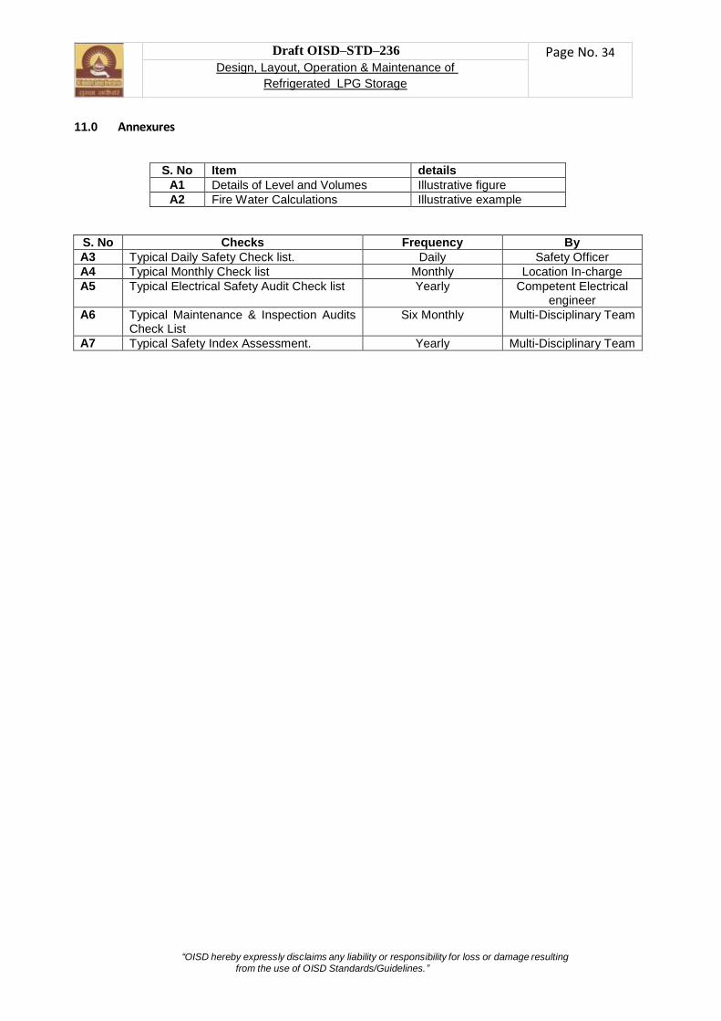
“OISD hereby expressly disclaims any liability or responsibility for loss or damage resulting
from the use of OISD Standards/Guidelines.”
Draft OISD–STD–236 Page No. 34
Design, Layout, Operation & Maintenance of
Refrigerated LPG Storage
11.0 Annexures
S. No Item details
A1 Details of Level and Volumes Illustrative figure
A2 Fire Water Calculations Illustrative example
S. No Checks Frequency By
A3 Typical Daily Safety Check list. Daily Safety Officer
A4 Typical Monthly Check list Monthly Location In-charge
A5 Typical Electrical Safety Audit Check list Yearly Competent Electrical engineer
A6 Typical Maintenance & Inspection Audits Check List
Six Monthly Multi-Disciplinary Team
A7 Typical Safety Index Assessment. Yearly Multi-Disciplinary Team

“OISD hereby expressly disclaims any liability or responsibility for loss or damage resulting
from the use of OISD Standards/Guidelines.”
Draft OISD–STD–236 Page No. 35
Design, Layout, Operation & Maintenance of
Refrigerated LPG Storage
12.0 REFERENCES
The following codes, standards and publications have either been referred to or used in the preparation of this document and the same shall be read in conjunction with this document:
S.No. Ref Code No Title
1 EEMUA: Pub
147 Recommendations for the Design and Construction of Refrigerated Liquefied Gas Storage Tanks
2 IP 9 Institute of Petroleum Liquefied Petroleum Gas Volume 1 Large Bulk Pressure Storage and Refrigerated LPG
3 API 2510 Design and Construction of LPG Installations
4 API 620 Design and Construction of Large, Welded, Low-pressure Storage Tanks
5 API 2350 Overfill Protection for Storage Tanks in Petroleum Facilities, Third Edition
6 API 2000 Venting Atmospheric and Low-pressure Storage Tanks
7 NFPA 58 Liquefied Petroleum gas Code
8 NFPA 59 Utility LP-Gas Plant Code
9 NFPA 59A, Standard for the Production, Storage, and Handling of Liquefied Natural Gas (LNG)
10 API 625 Tank Systems for Refrigerated Liquefied Gas Storage
11 ACI 376 Code Requirements for Design and Construction of Concrete Structures for the Containment of Refrigerated Liquefied Gases and Commentary
12 AGA XK 0101 Purging Principles and Practice
13 EN 14620:1-4
Design and manufacture of site built, vertical, cylindrical, flat-bottomed steel tanks for the storage of refrigerated, liquefied gasses with operating temperatures between 0 °C and –165 °C Part 1 to Part 4.
14 ASTM C165 Standard Test Method for Measuring Compressive Properties of Thermal Insulations
15 ASTM C177 Standard Test Method for Steady-State Heat Flux Measurements and Thermal Transmission Properties by Means of the Guarded-Hot-Plate Apparatus
16 ASTM C240 Standard Test Methods of Testing Cellular Glass Insulation Block
17 ASTM C552 Standard Specification for Cellular Glass Insulation
18 ASTM C549 Standard Specification for Perlite Loose Fill Insulation
19 ASTM C764 Standard Specification for Mineral Fiber Loose-Fill Thermal Insulation
20 ASME B31.3 Process Piping
21 OISD-STD-105 Work Permit System
22 IS:875 Code of Practice for Design loads (Other than Earthquakes) for buildings and other structures.
23 IS:1893 (Part 1)-
2002 IS 1893 (Part 1) (2002, Reaffirmed 2007): Criteria for Earthquake Resistant Design of Structures,
24 OISD-STD-144 Liquefied Petroleum Gas Installations
25 IS 5571 Guide for selection of electrical equipment for hazardous areas.
26 IS 5572 Classification of Hazardous area having flammable gases and vapours for electrical installation.
27 IS 3043 Code of Practice for Earthing.
28 IS 15652 Insulating mats for electrical purposes
29 OISD-STD-155 “Personal Protective Equipment” to be referred for details on selection, use and maintenance of electrical PPEs.
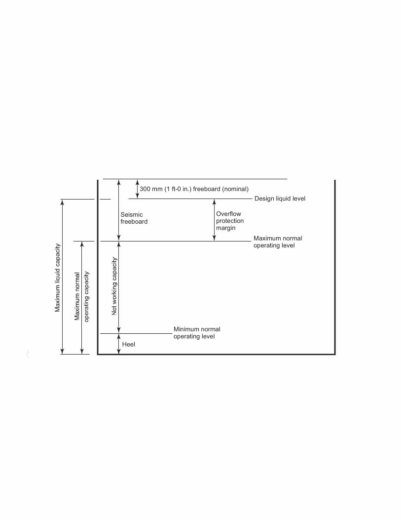
���������������������������������������
�����������������
�������������������
��������������������������
�����������������������������
�����������������������������
����
����������

�����������������������������������������������������������������������������������������������������������������������������������������������������������������������������������������������������������������

A.
Sl. No.Location Area / size Area / size
Area of Single
largest zone
Area of
adjacent zones
Spray Density
(LPM)
Water Req /
Hour Cu Mtr per
hr
1 Tank Truck Loading / Unloading Facility 30 15 450 0 10.2 275
2 a. Refrigerated Tank Surafce area 35 20 2198 2198 3 791
b. Refrigerated Tank Roof area 35 961.6 961.63 3 346
c. Refrigerated Tank Total area 1137
3 LPG Pump House 20 10 200 0 20.4 245
4 Compressor House 30 20 600 0 20.4 734
5 Rail Loadinf Facility 30 15 450 900 10.2 826
6 Process Area 20 15 300 0 10.2 184
7 Horton Sphere 18 1017.4 2034.7 10.2 1868
8 Shed 40 12 480 960 10.2 881
B. Single largest area covered by Medium velocity Water Sprinkler System is Horton Sphere: 1868
C. Water Requirement for operating 2 nos. Monitors @ 144 Cum/Hr: 288
D. Total Water requirement ( B+C ): 2156 Cum/Hr
E. No. of Fire Water Pumps Required ( 410 Cum/Hr capacity): 2156/410= 5.3 Say 6
F No. of standby pumps required ( minimum 50% of main pump): 2 2
G Total number of Fire Water Pumps Required ( 6 + 2)= 8 8
H Total No. of main Fire Water Pumps Available : 6
I Fire water storage tanks capacity requied for 4 Hrs fire fighting (6 x 4 x 410): 9840 Kl
J Minimum two nos of tanks shall be provided.
Annexure A2
Fire Water / Pump Requirement Calculation
Medium Velocity Water Spray System (MVWSS):
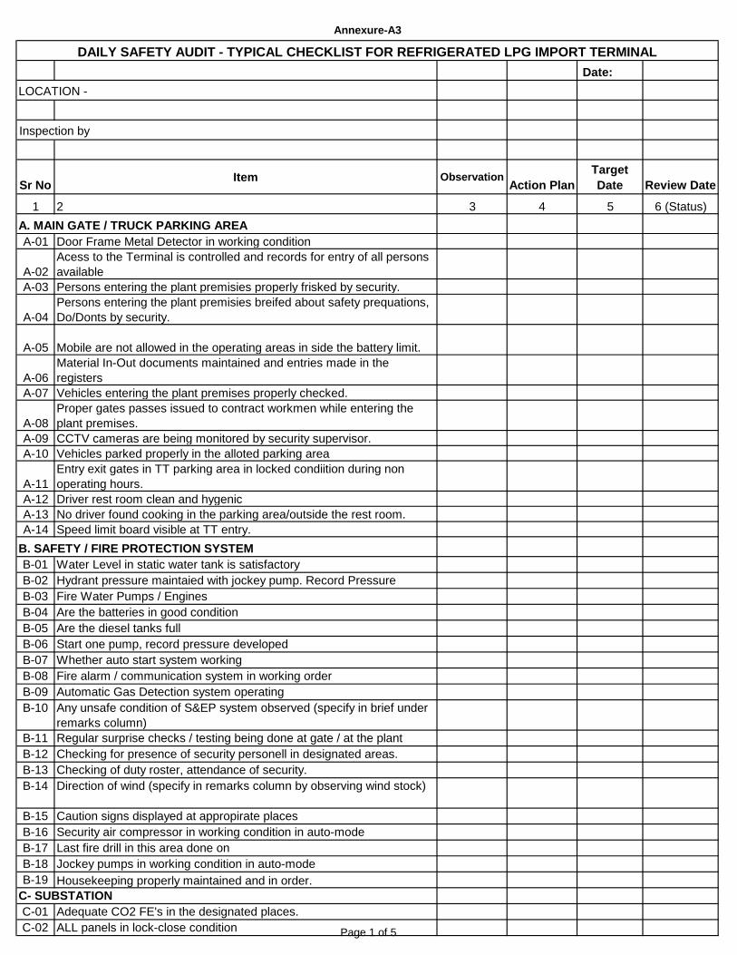
Date:
LOCATION -
Audit / Inspection by
Sr NoItem Observation
Action Plan
Target
Date Review Date
1 2 3 4 5 6 (Status)
A-01 Door Frame Metal Detector in working condition
A-02
Acess to the Terminal is controlled and records for entry of all persons
available
A-03 Persons entering the plant premisies properly frisked by security.
A-04
Persons entering the plant premisies breifed about safety prequations,
Do/Donts by security.
A-05 Mobile are not allowed in the operating areas in side the battery limit.
A-06
Material In-Out documents maintained and entries made in the
registers
A-07 Vehicles entering the plant premises properly checked.
A-08
Proper gates passes issued to contract workmen while entering the
plant premises.
A-09 CCTV cameras are being monitored by security supervisor.
A-10 Vehicles parked properly in the alloted parking area
A-11
Entry exit gates in TT parking area in locked condiition during non
operating hours.
A-12 Driver rest room clean and hygenic
A-13 No driver found cooking in the parking area/outside the rest room.
A-14 Speed limit board visible at TT entry.
B-01 Water Level in static water tank is satisfactory
B-02 Hydrant pressure maintaied with jockey pump. Record Pressure
B-03 Fire Water Pumps / Engines
B-04 Are the batteries in good condition
B-05 Are the diesel tanks full
B-06 Start one pump, record pressure developed
B-07 Whether auto start system working
B-08 Fire alarm / communication system in working order
B-09 Automatic Gas Detection system operating
B-10 Any unsafe condition of S&EP system observed (specify in brief under
remarks column)
B-11 Regular surprise checks / testing being done at gate / at the plant
B-12 Checking for presence of security personell in designated areas.
B-13 Checking of duty roster, attendance of security.
B-14 Direction of wind (specify in remarks column by observing wind stock)
B-15 Caution signs displayed at appropirate places
B-16 Security air compressor in working condition in auto-mode
B-17 Last fire drill in this area done on
B-18 Jockey pumps in working condition in auto-mode
B-19 Housekeeping properly maintained and in order.
C-01 Adequate CO2 FE's in the designated places.
C-02 ALL panels in lock-close condition
Annexure-A3
DAILY SAFETY AUDIT - TYPICAL CHECKLIST FOR REFRIGERATED LPG IMPORT TERMINAL
B. SAFETY / FIRE PROTECTION SYSTEM
A. MAIN GATE / TRUCK PARKING AREA
C- SUBSTATION
Page 1 of 5

Sr NoItem Observation
Action Plan
Target
Date Review Date
C-03 Adequate lighting in the substation
C-04 Panel indication lamps working.
C-05 Housekeeping properly maintained and in order.
D-01 Whether water draining sampling done under constant supervision
D-02 Earthing connection apparently sound
D-03 Cathodic Protection healthy
D-04 Whether level instruments are working
D-05 High level alarm in working condition (test check)
D-06 Portable fire extinguishers in postion
D-07 Water spray / sprinkler system apparently OKD-08 Housekeeping is in order
D-09 Gas Detection system working
D-10 Any sign of LPG leakage
D-11 Any settlement of vessel observed
D-12 Condition of Water Seal
D-13 ROVs on remote mode
D-14 Bonding across flanges visible
D-15 API 52 pump tripping in Buffer tank in working condition.
D-16 Last fire drill in this area done on
E-01 Earthing connection apparently sound
E-02 Whether level instruments are working
E-03 High level alarm in working condition (test check)
E-04 Portable fire extinguishers in postion
E-05 Water spray / sprinkler system apparently OK
E-06 Housekeeping is in order
E-07 Gas Detection system working
E-08 Any sign of LPG leakage
E-09 Any settlement of tank observed
E-10 Condition of Water Seal in dyke area
E-11 ROVs on remote mode
E-12 Bonding across flanges visible
E-13 High Pressure tripping-interlock with import valves.
E-14 Auto Flare of tanks in working condition.
E-15 Portable fire extinguishers in postion
E-16 The insulation cover and cladding of cryogenic tanks is in good
condition
E-17 Last fire drill in this area done on
E-18 vapour trap is provided as per design.
E-19 The upstream and down stream valves of TSV on intank pump
discharge line are in open and locked position
E-20 The pressure gauges on intank pump discharge line on tank top are in
working condition
E-21 The updtream valve of SRV and VRV should be in open locked
position
F-01 Any visible sign of LPG leakage
F-02 Earthing connection apparently sound
F-03 Whether hose condition / connections are proper
F-04 Are these properly plugged if not in use
F-05 House Keeping in order
F-06 Portable fire extinguishers in postion
F-07 Water spray / sprinkler system apparently OK
F-08 No open wire / improper glanding visible.
D. BUFFER TANK AREA
F. TANK WAGON LOADING AREA
E. PROPANE/BUTANE TANK AREA
Page 2 of 5
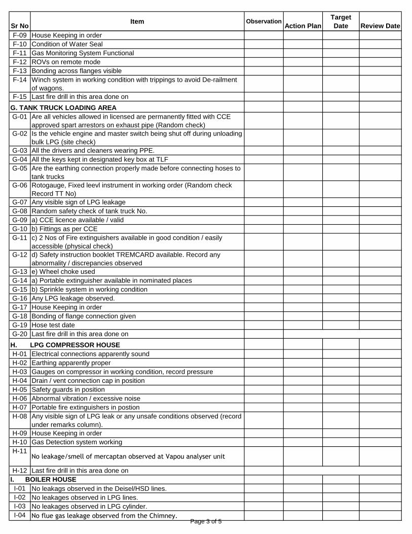
Sr NoItem Observation
Action Plan
Target
Date Review Date
F-09 House Keeping in order
F-10 Condition of Water Seal
F-11 Gas Monitoring System Functional
F-12 ROVs on remote mode
F-13 Bonding across flanges visible
F-14 Winch system in working condition with trippings to avoid De-railment
of wagons.
F-15 Last fire drill in this area done on
G-01 Are all vehicles allowed in licensed are permanently fitted with CCE
approved spart arrestors on exhaust pipe (Random check)
G-02 Is the vehicle engine and master switch being shut off during unloading
bulk LPG (site check)
G-03 All the drivers and cleaners wearing PPE.
G-04 All the keys kept in designated key box at TLF
G-05 Are the earthing connection properly made before connecting hoses to
tank trucks
G-06 Rotogauge, Fixed leevl instrument in working order (Random check
Record TT No)
G-07 Any visible sign of LPG leakage
G-08 Random safety check of tank truck No.
G-09 a) CCE licence available / valid
G-10 b) Fittings as per CCE
G-11 c) 2 Nos of Fire extinguishers available in good condition / easily
accessible (physical check)
G-12 d) Safety instruction booklet TREMCARD available. Record any
abnormality / discrepancies observed
G-13 e) Wheel choke used
G-14 a) Portable extinguisher available in nominated places
G-15 b) Sprinkle system in working condition
G-16 Any LPG leakage observed.
G-17 House Keeping in order
G-18 Bonding of flange connection given
G-19 Hose test date
G-20 Last fire drill in this area done on
H-01 Electrical connections apparently sound
H-02 Earthing apparently proper
H-03 Gauges on compressor in working condition, record pressure
H-04 Drain / vent connection cap in position
H-05 Safety guards in position
H-06 Abnormal vibration / excessive noise
H-07 Portable fire extinguishers in postion
H-08 Any visible sign of LPG leak or any unsafe conditions observed (record
under remarks column).
H-09 House Keeping in order
H-10 Gas Detection system working
H-11No leakage/smell of mercaptan observed at Vapou analyser unit
H-12 Last fire drill in this area done on
I-01 No leakags observed in the Deisel/HSD lines.
I-02 No leakages observed in LPG lines.
I-03 No leakages observed in LPG cylinder.
I-04 No flue gas leakage observed from the Chimney.
G. TANK TRUCK LOADING AREA
H. LPG COMPRESSOR HOUSE
I. BOILER HOUSE
Page 3 of 5
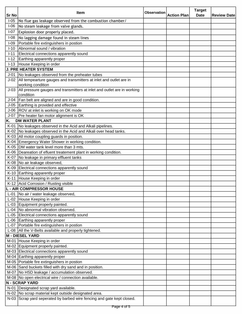
Sr NoItem Observation
Action Plan
Target
Date Review Date
I-05 No flue gas leakage observed from the combustion chamber/
I-06 No steam leakage from valve glands.
I-07 Explosion door properly placed.
I-08 No lagging damage found in steam lines
I-09 Portable fire extinguishers in postion
I-10 Abnormal sound / vibration
I-11 Electrical connections apparently sound
I-12 Earthing apparently proper
I-13 House Keeping in order
J-01 No leakages observed from the preheater tubes
J-02 All tempearture gauges and transmitters at inlet and outlet are in
working condition
J-03 All pressure gauges and transmitters at inlet and outlet are in working
condition
J-04 Fan belt are aligned and are in good condition.
J-05 Earthing is provided and effective
J-06 ROV at inlet is working on OK mode
J-07 Pre heater fan motor alignment is OK
K-01 No leakages observed in the Acid and Alkali pipelines.
K-02 No leakages observed in the Acid and Alkali over head tanks.
K-03 All motor coupling guards in position.
K-04 Emergency Water Shower in working condition.
K-05 DM water tank level more than 3 mts.
K-06 Deareation of efluent treatement plant in working condition.
K-07 No leakage in primary effluent tanks
K-08 No air leakage observed,
K-09 Electrical connections apparently sound
K-10 Earthing apparently proper
K-11 House Keeping in order
K-12 Acid Corrosion / Rusting visible
L-01 No air / water leakage observed,
L-02 House Keeping in order
L-03 Equipment properly painted.
L-04 No abnormal vibration observed.
L-05 Electrical connections apparently sound
L-06 Earthing apparently proper
L-07 Portable fire extinguishers in postion
L-08 All the V-Belts available and properly tightened.
M-01 House Keeping in order
M-02 Equipment properly painted.
M-03 Electrical connections apparently sound
M-04 Earthing apparently proper
M-05 Portable fire extinguishers in postion
M-06 Sand buckets filled with dry sand and in position.
M-07 No HSD leakage / accumulation observed.
M-08 No open electrical wire / connection available.
N-01 Designated scrap yard available.
N-02 No scrap material kept outside designated area.
N-03 Scrap yard seperated by barbed wire fencing and gate kept closed.
J. PRE HEATER SYSTEM
K. DM WATER PLANT
L - AIR COMPRESSOR HOUSE
M - DIESEL YARD
N - SCRAP YARD
Page 4 of 5
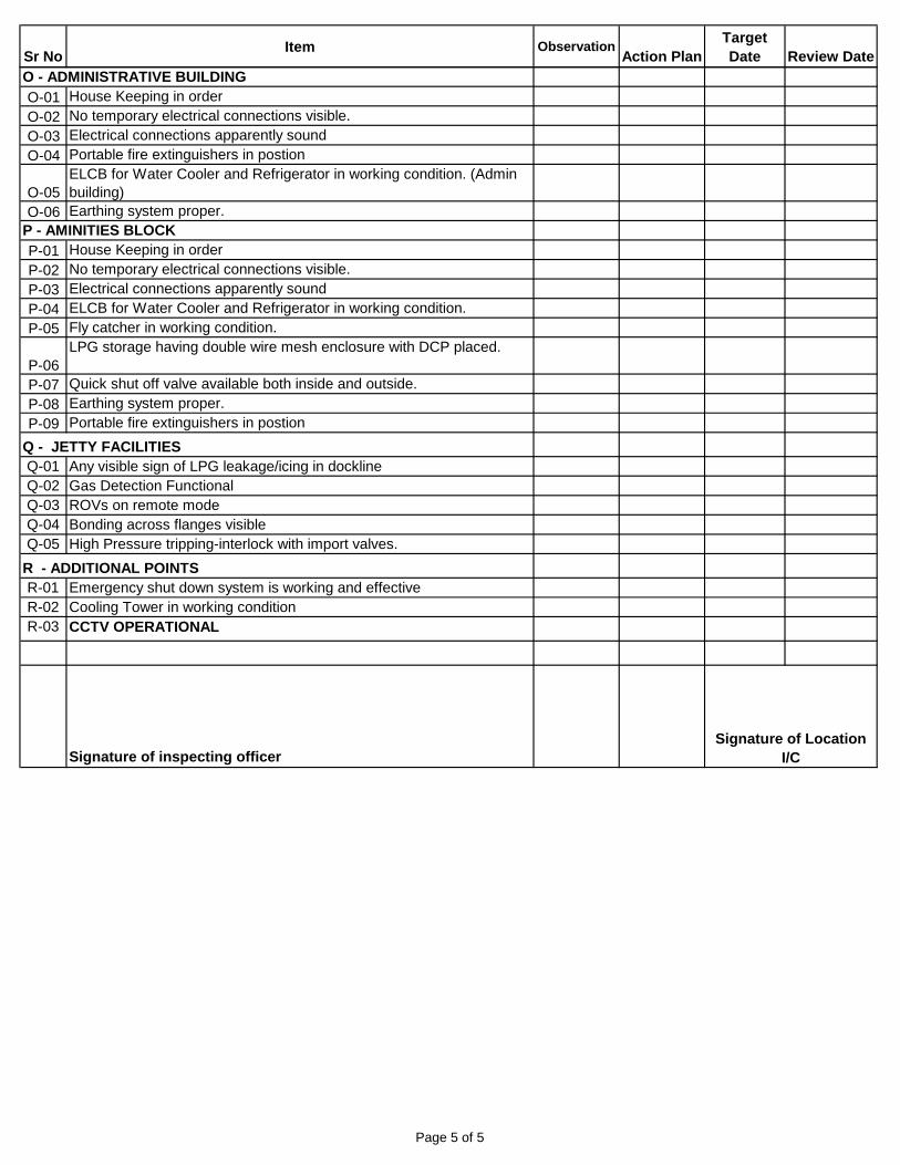
Sr NoItem Observation
Action Plan
Target
Date Review Date
O-01 House Keeping in order
O-02 No temporary electrical connections visible.
O-03 Electrical connections apparently sound
O-04 Portable fire extinguishers in postion
O-05
ELCB for Water Cooler and Refrigerator in working condition. (Admin
building)
O-06 Earthing system proper.
P-01 House Keeping in order
P-02 No temporary electrical connections visible.
P-03 Electrical connections apparently sound
P-04 ELCB for Water Cooler and Refrigerator in working condition.
P-05 Fly catcher in working condition.
P-06
LPG storage having double wire mesh enclosure with DCP placed.
P-07 Quick shut off valve available both inside and outside.
P-08 Earthing system proper.
P-09 Portable fire extinguishers in postion
Q-01 Any visible sign of LPG leakage/icing in dockline
Q-02 Gas Detection Functional
Q-03 ROVs on remote mode
Q-04 Bonding across flanges visible
Q-05 High Pressure tripping-interlock with import valves.
R-01 Emergency shut down system is working and effective
R-02 Cooling Tower in working condition
R-03 CCTV OPERATIONAL
Signature of inspecting officer
Signature of Location
I/C
P - AMINITIES BLOCK
Q - JETTY FACILITIES
R - ADDITIONAL POINTS
O - ADMINISTRATIVE BUILDING
Page 5 of 5

Name of the location Date
Sl No Description
1 All statutory records available and updatedLicense / Test
Certificate No.Validity
Remarks/
Renewal
Application
Date1.1 PESO Licenses
1.12 License to Store Compressed Gas in Pressure Vessels
1.13 Storage of HSD inside premises for Own Use
1.14 Updated Plant & equipment Layout duly approved.
1.2 Weights & Measures
1.22 Stamping of Weigh Bridge (TLF IN & OUT)
1.23 Stamping of Weigh Bridge (RLF)
1.25 Stamping of Standard Weights
1.26 Stamping of MFM (RLF/TLF)
1.3 Factory Related
1.31 Factory License
1.32 Copy of Notification of Occupier issued by MOPNG
available
1.4 Pollution Control
1.41 Consent under Air (Prevention and Control of Pollution) Act,
1981
1.42 Consent under Water (Prevention and Control of Pollution)
Act, 1974
1.5 Labour Related
1.51 PF no. & ESI Registration no. of Location, if applicable
1.52 Registration under Contract labour ( Regulation and &
Abolition )Act 1970
1.53 License details of Contractors under Contract Labour (Reg.
& Abo.) Act.
All statutory records available and updated License / Test
Certificate No.
Validity Remarks/
Renewal
Application
Date
2 Test Certificates
2.1 Valid test certificates available for
2.11 Hydrotest of LPG STORAGE VESSELS
2.12 NDT and Hydrotest records for Underground / aboveground
LPG pipelines
2.13 NDT and Hydrotest records for Jetty LPG pipelines
2.14
NDT & Hydrotest for other Pressure vessels as per Factory
Act
2.15 SRVs & TSVs
2.16 Lifting tools & Tackles, chain pulley block
2.17 Fire Water Line NDT
2.18 Fire Water Tanks cleaning details
2.19 LPG Hose Testing
2.20 Pr gauge / Temp gauge testing records
2.21 Relay Test record
2.22 Earth Pit Testing
2.23 Motor & LT / HT Cable IR testing
2.24 Electrical Hand Gloves
2.25 Insulating mats/Rubber Mats for Electrical purpose
2.26 Transformer Oil Test
Annexure-A4
Monthly Checks
Typical Monthly Check list

3 SAFETY3.1 Audit Compliance Status
Name of Audit Total Points Complied Remarks
3.1.1 OISD- ESA
3.1.2 OISD- surprise
3.1.3 MDT Audit
3.1.4 Electrical Audit
3.1.5 Security Audit
3.1.6 Internal Audit
Remarks
3.2 Emergency lighting system provided in strategic locations &
system working satisfactorily
3.3 Records of `Daily Safety Audit' reviewed by Loc.In-Charge
3.4 Work Permit system viz Hot, Cold, Electrical and Working
at height (issue and closure) checked
3.5 First-Aid facilities maintained
3.6 Safety Circle / Committee meeting are conducted . Record
last meeting dates
3.7 Fire alarm (electrical & hand sirens) working satisfactorily
3.8 Communication system (PA Paging / VHF) working
satisfactorily
3.9 Flame proof Torches in working condition
3.10 Automatic Gas Detection system : Working & Calibration
records available
3.11 Record Pressure at farthest end of hydrant network
3.12 Interlock shutdown system as per OISD 11.11 (iv) checked
and found ok
Remarks
3.13 Fire Protection System on auto. Test check atleast one DV
through QB.
3.14 Fire engine - Sequence logic tested and found OK.
3.15 Fuel gauge of HSD tanks ( DG & fire engines) working and
levels OK
3.16 Fire Water storage tank : Indicate Requirement in KL and
availabilty in KL
3.17 Fire Extinguishers / Fire Hoses kept at nominated places
3.18 No temporary electrical connection existing
3.19
Safety Equipment inventory reviewed for shortfall and
action taken
3.20 Any unsafe conditions observed in TTs Parking area
3.21 Important DO's & Dont's , Operating Instructions, displayed
prominently in respective places
3.22 SOP displayed at operating locations
3.23
Trainings being conducted and records available as per
OISD 154
4 SECURITY
4.1 Fencing around plant is in proper condition
4.2 Tower lights illumination checked and found ok.
4.3 All records at the gates are maintained and reviewed as per
norms
4.4 Material In-Out Register (Corporation / Contractor)
4.5 Returnable material register
4.6 Visitor's register
4.7 Gatepass systems
4.8 CCTV functional
Status
Status

4.9 ACS functional
4.10 DFMD & HHMD in use
4.11 Under vehicle search mirror in use
4.12 Updated list of authorised signatory available.
5 Operations
5.1 One panel in PMCC checked for following
a Cleanliness
b Fuse/rating
c Relay setting
5.2 ROVs working Satisfactorily
5.21 Cooling water flow adequate and cooling fans in working
condition.
5.22 Whether on line analyser working satisfactorily.
5.23 DM water level in DM tank above 3 mtrs.
5.24 No acid / alkali leak visible
5.25 No HSD / LPG leak at boiler.
5.26 No Flue / Steam leak observed.
5.27 Whether logsheets/records are maintained for daily
activities at PPH/PMCC/FPH/CCR
5.28 Loading hoses of Tank wagon Gantry when not in use
positioned correctly, ends blinded.
5.29 Open ends of Unloading arms/hoses capped when not in
use at TLD
5.3 Eight studs used for connection of flanges at TLD
5.31 Wheel chokes available & chained at TLD
5.32 No portion of pipe length found buried with soil or
undergrowth
5.33 SRVs are locked in open position
5.34 Vent pipes of Safety Relief valves on LPG storage vessels
are provided with rain caps & weep holes (connected with
drain pipe and isolation valve).
5.35 No LPG leakages observed in operating areas.
6 MAINTENANCE
6.1 Double independent earthing connection for all motors
/structures/vessels/ pipelines provided
6.2 FLP condition of electrical equipments intact
6.3 Push button earthed properly
6.4 All LPG Vent lines provided with double mesh and properly
earthed
6.6 No leakage from mechanical seals of LPG pumps
6.7 Pipeline colour code system maintained
6.8 Bonding connections maintained for pipelines, Vessels,
conveyors, gantry.
6.9 Two independent level instruments provided in storage
vessels & are in working condition
6.10 HLA interlock with ROV on storage vessels working
6.11 Stores Module (SAP-MM module ) implemented for
equipment and consumable stores
6.12 Whether functional locations in PM module created and
tasklists for these implemented
6.13 Whether all continuous monitoring devices are periodically
checked & calibrated
6.14 Cathodic Protection System of Mounded storage system
checked and found ok
6.15 Condition of the mound checked / No settlement observed.
6.16
BI monthly M&I indexing being carried out and corrective
action taken
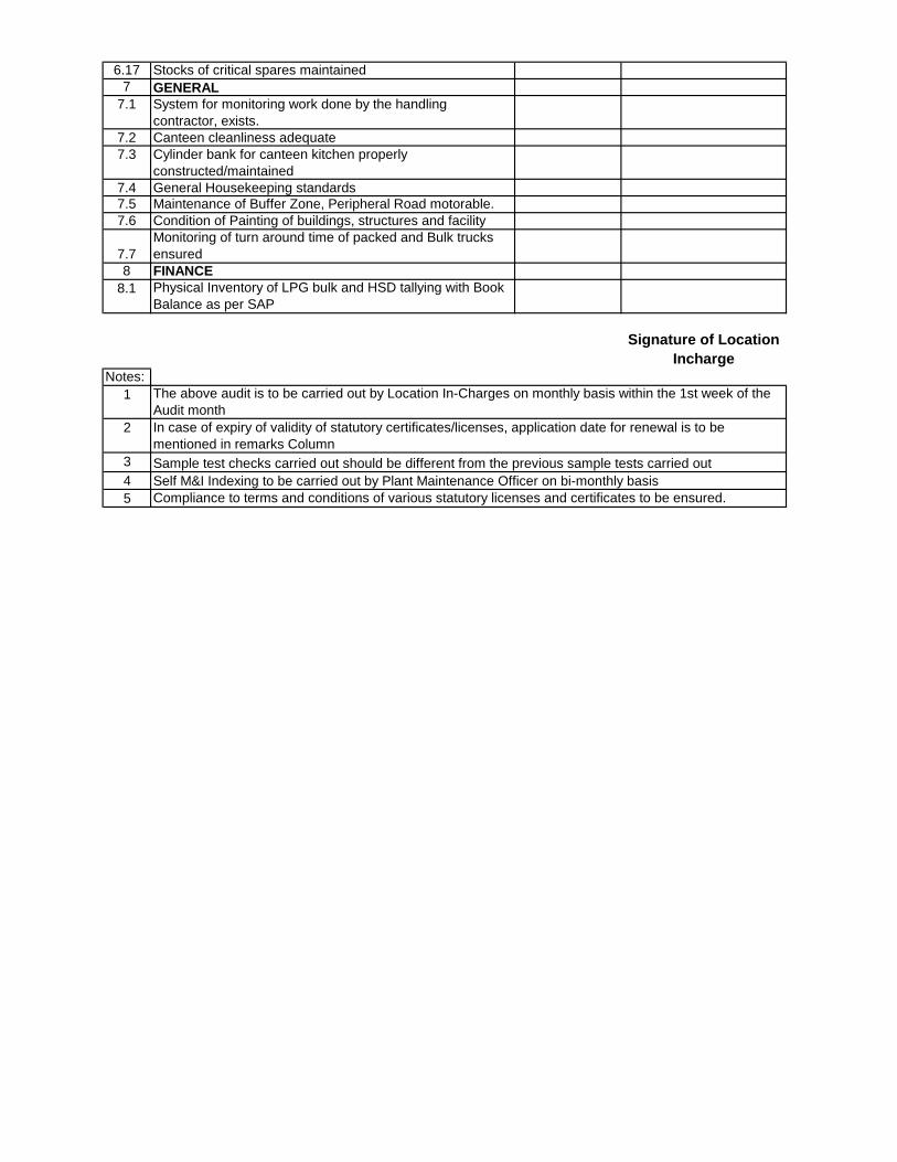
6.17 Stocks of critical spares maintained
7 GENERAL
7.1 System for monitoring work done by the handling
contractor, exists.
7.2 Canteen cleanliness adequate
7.3 Cylinder bank for canteen kitchen properly
constructed/maintained
7.4 General Housekeeping standards
7.5 Maintenance of Buffer Zone, Peripheral Road motorable.
7.6 Condition of Painting of buildings, structures and facility
7.7
Monitoring of turn around time of packed and Bulk trucks
ensured
8 FINANCE
8.1 Physical Inventory of LPG bulk and HSD tallying with Book
Balance as per SAP
Notes:
1
2
3
4
5
The above audit is to be carried out by Location In-Charges on monthly basis within the 1st week of the
Audit month
In case of expiry of validity of statutory certificates/licenses, application date for renewal is to be
mentioned in remarks Column
Sample test checks carried out should be different from the previous sample tests carried out
Self M&I Indexing to be carried out by Plant Maintenance Officer on bi-monthly basis
Compliance to terms and conditions of various statutory licenses and certificates to be ensured.
Signature of Location
Incharge
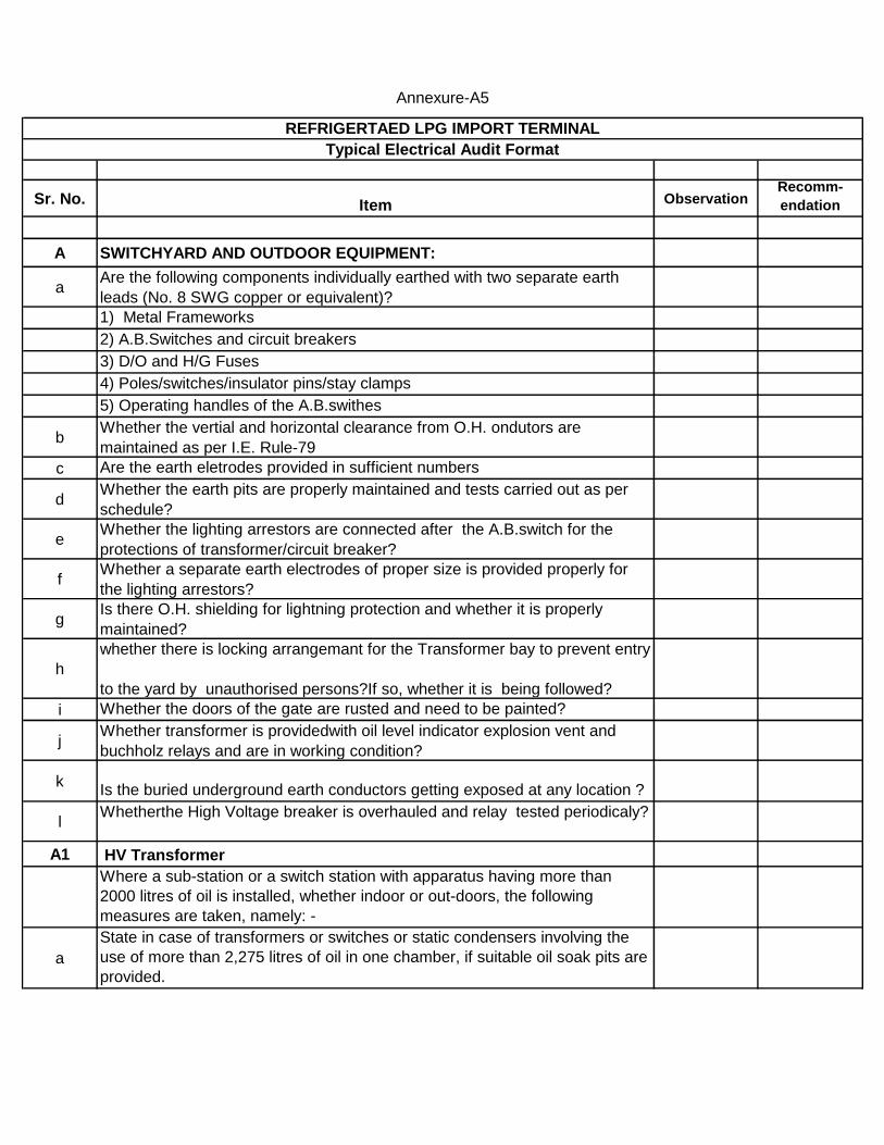
Sr. No. Item ObservationRecomm-
endation
A SWITCHYARD AND OUTDOOR EQUIPMENT:
aAre the following components individually earthed with two separate earth
leads (No. 8 SWG copper or equivalent)?
1) Metal Frameworks
2) A.B.Switches and circuit breakers
3) D/O and H/G Fuses
4) Poles/switches/insulator pins/stay clamps
5) Operating handles of the A.B.swithes
bWhether the vertial and horizontal clearance from O.H. ondutors are
maintained as per I.E. Rule-79
c Are the earth eletrodes provided in sufficient numbers
dWhether the earth pits are properly maintained and tests carried out as per
schedule?
eWhether the lighting arrestors are connected after the A.B.switch for the
protections of transformer/circuit breaker?
fWhether a separate earth electrodes of proper size is provided properly for
the lighting arrestors?
gIs there O.H. shielding for lightning protection and whether it is properly
maintained?
h
whether there is locking arrangemant for the Transformer bay to prevent entry
to the yard by unauthorised persons?If so, whether it is being followed?
i Whether the doors of the gate are rusted and need to be painted?
jWhether transformer is providedwith oil level indicator explosion vent and
buchholz relays and are in working condition?
kIs the buried underground earth conductors getting exposed at any location ?
lWhetherthe High Voltage breaker is overhauled and relay tested periodicaly?
A1 HV Transformer
Where a sub-station or a switch station with apparatus having more than
2000 litres of oil is installed, whether indoor or out-doors, the following
measures are taken, namely: -
a
State in case of transformers or switches or static condensers involving the
use of more than 2,275 litres of oil in one chamber, if suitable oil soak pits are
provided.
REFRIGERTAED LPG IMPORT TERMINAL
Typical Electrical Audit Format
Annexure-A5
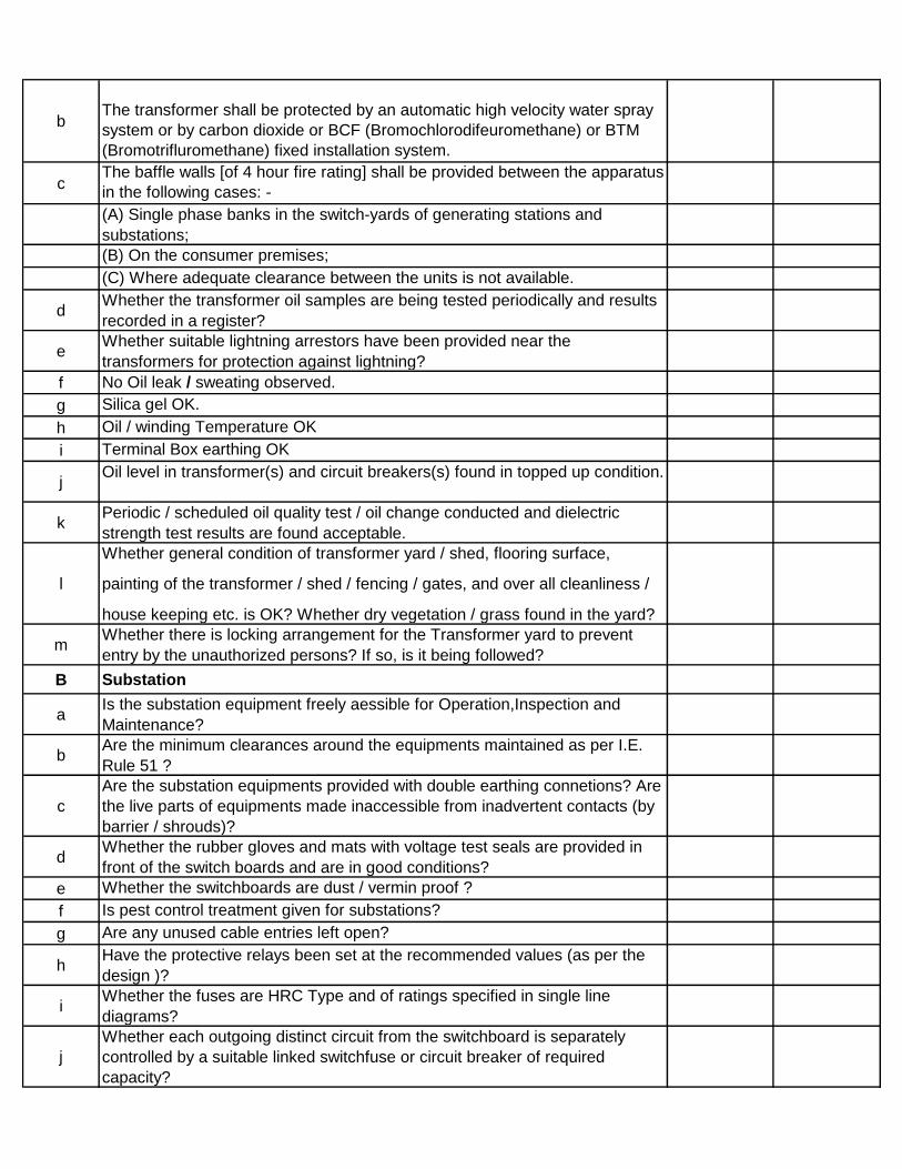
bThe transformer shall be protected by an automatic high velocity water spray
system or by carbon dioxide or BCF (Bromochlorodifeuromethane) or BTM
(Bromotrifluromethane) fixed installation system.
cThe baffle walls [of 4 hour fire rating] shall be provided between the apparatus
in the following cases: -
(A) Single phase banks in the switch-yards of generating stations and
substations;
(B) On the consumer premises;
(C) Where adequate clearance between the units is not available.
dWhether the transformer oil samples are being tested periodically and results
recorded in a register?
eWhether suitable lightning arrestors have been provided near the
transformers for protection against lightning?
f No Oil leak / sweating observed.
g Silica gel OK.
h Oil / winding Temperature OK
i Terminal Box earthing OK
jOil level in transformer(s) and circuit breakers(s) found in topped up condition.
kPeriodic / scheduled oil quality test / oil change conducted and dielectric
strength test results are found acceptable.
l
Whether general condition of transformer yard / shed, flooring surface,
painting of the transformer / shed / fencing / gates, and over all cleanliness /
house keeping etc. is OK? Whether dry vegetation / grass found in the yard?
mWhether there is locking arrangement for the Transformer yard to prevent
entry by the unauthorized persons? If so, is it being followed?
B Substation
aIs the substation equipment freely aessible for Operation,Inspection and
Maintenance?
bAre the minimum clearances around the equipments maintained as per I.E.
Rule 51 ?
c
Are the substation equipments provided with double earthing connetions? Are
the live parts of equipments made inaccessible from inadvertent contacts (by
barrier / shrouds)?
dWhether the rubber gloves and mats with voltage test seals are provided in
front of the switch boards and are in good conditions?
e Whether the switchboards are dust / vermin proof ?
f Is pest control treatment given for substations?
g Are any unused cable entries left open?
hHave the protective relays been set at the recommended values (as per the
design )?
iWhether the fuses are HRC Type and of ratings specified in single line
diagrams?
j
Whether each outgoing distinct circuit from the switchboard is separately
controlled by a suitable linked switchfuse or circuit breaker of required
capacity?
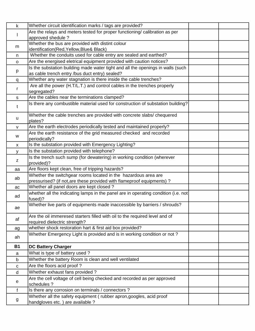
k Whether circuit identification marks / tags are provided?
lAre the relays and meters tested for proper functioning/ calibration as per
approved shedule ?
mWhether the bus are provided with distint colour
identification(Red,Yellow,Blue& Black)
n Whether the conduits used for cable entry are sealed and earthed?
o Are the energised eletrical equipment provided with caution notices?
pIs the substation building made water tight and all the openings in walls (such
as cable trench entry /bus duct entry) sealed?
q Whether any water stagnation is there inside the cable trenches?
r Are all the power (H.T/L.T.) and control cables in the trenches properly
segregated?
s Are the cables near the terminations clamped?
tIs there any combustible material used for construction of substation building?
uWhether the cable trenches are provided with concrete slabs/ chequered
plates?
v Are the earth electrodes periodically tested and maintained properly?
wAre the earth resistance of the grid measured checked and recorded
periodically?
x Is the substation provided with Emergency Lighting?
y Is the substation provided with telephone?
zIs the trench such sump (for dewatering) in working condition (wherever
provided)?
aa Are floors kept clean, free of tripping hazards?
abWhether the switchgear rooms located in the hazardous area are
pressurised? (if not,are these provided with flameproof equipments) ?
ac Whether all panel doors are kept closed ?
adwhether all the indicating lamps in the panel are in operating condition (i.e. not
fused)?
aeWhether live parts of equipments made inaccessible by barriers / shrouds?
afAre the oil immeresed starters filled with oil to the required level and of
required dielectric strength?
ag whether shock restoration hart & first aid box provided?
ahWhether Emergency Light is provided and is in working condition or not ?
B1 DC Battery Charger
a What is type of battery used ?
b Whether the battery Room is clean and well ventilated
c Are the floors acid proof ?
d Whether exhaust fans provided ?
eAre the cell voltage of cell being checked and recorded as per approved
schedules ?
f Is there any corrosion on terminals / connectors ?
gWhether all the safety equipment ( rubber apron,googles, acid proof
handgloves etc. ) are available ?
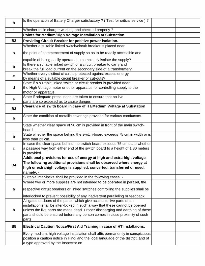
hIs the operation of Battery Charger satisfactory ? ( Test for critical service ) ?
i Whether tricle charger working and checked properly ?
Points for Medium/High Voltage Installation at Substation
B2 Providing Circuit Breaker for positive power isolation.
a
Whether a suitable linked switch/circuit breaker is placed near
the point of commencement of supply so as to be readily accessible and
capable of being easily operated to completely isolate the supply?
bIs there a suitable linked switch or a circuit breaker to carry and
break the full load current on the secondary side of a transformer?
cWhether every distinct circuit is protected against excess energy
by means of a suitable circuit breaker or cut-outs?
d
State if a suitable linked switch or circuit breaker is provided near
the High Voltage motor or other apparatus for controlling supply to the
motor or apparatus.
eState if adequate precautions are taken to ensure that no live
parts are so exposed as to cause danger.
B3Clearance of swith board in case of HT/Medium Voltage at Substation
aState the condition of metallic coverings provided for various conductors.
State whether clear space of 90 cm is provided in front of the main switch-
board.
bState whether the space behind the switch-board exceeds 75 cm.in width or is
less than 23 cm.
c
In case the clear space behind the switch-board exceeds 75 cm state whether
a passage way from either end of the switch board to a height of 1.80 meters
is provided.
B4
Additional provisions for use of energy at high and extra-high voltage-
The following additional provisions shall be observed where energy at
high or extrahigh voltage is supplied, converted, transferred or used,
namely: -
Suitable inter-locks shall be provided in the following cases: -
a
Where two or more supplies are not intended to be operated in parallel, the
respective circuit breakers or linked switches controlling the supplies shall be
interlocked to prevent possibility of any inadvertent paralleling or feedback;
b
All gates or doors of the panel which give access to live parts of an
installation shall be inter-locked in such a way that these cannot be opened
unless the live parts are made dead. Proper discharging and earthing of these
parts should be ensured before any person comes in close proximity of such
parts;
B5 Electrical Caution Notice/First Aid Training in case of HT installaions.
Every medium, high voltage installation shall affix permanently in conspicuous
position a caution notice in Hindi and the local language of the district, and of
a type approved by the Inspector on

a
Every motor, generator, transformer and other electrical plant and equipment
together with apparatus used for controlling or regulating the same.
All supports of high, and extra-high voltage overhead lines
b
Provided that where it is not possible to affix such notices on any generator,
motor, transformer or other apparatus, they shall be affixed as near as
possible thereto: Provided further that where the generator, motor,
transformer or other apparatus is within an enclosure, one notice affixed to
the said enclosure shall be sufficient for the purpose of this rule.
c In the case of generating and enclosed stations have fire-buckets, filled with
clean dry sand, been conspicuously marked and kept in convenient situations
in addition to fire-extinguishers suitable for dealing with electric fires?
dState if First Aid Boxes or Cupboards conspicuously marked and properly
equipped are provided and maintained.
e Is some staff trained in First Aid Treatment?
f
In every manned high voltage or extra-high voltage generating station,
substation or switch station, an artificial respirator shall be provided and kept
in goodworking condition
B6 LV Transformer / Lighting Transformer
aCable terminations / horn gap / CTPT / main circuit breakers etc. is OK.
b Foundation OK.
c Transformer positioned properly.
d No Oil leak / sweating observed.
e Silica gel OK.
f Oil / winding Temperature OK
g Terminal Box earthing OK
hOil level in transformer(s) and circuit breakers(s) found in topped up condition.
Periodic / scheduled oil quality test / oil change conducted and dielectric
strength test results are found acceptable.
i
Whether general condition of transformer yard / shed, flooring surface,
painting of the transformer / shed / fencing / gates, and over all cleanliness /
house keeping etc. is OK? Whether dry vegetation / grass found in the yard?
jWhether there is locking arrangement for the Transformer yard to prevent
entry by the unauthorized persons? If so, is it being followed?
kIs the buried underground earth conductors getting exposed at any location ?
C DG Room
a Is the neutral of the generator provided with an isolator?
b Whether DGs is provided with two independent body earthing?
cWhether the neutral of the generator is earthed by minimum two separate
earth connections and whether the earthing is after the isolator?

dWhether the wires / cables near the Generator / Generator to switch board
are housed in metallic conduit and the conduit is earthed?
eWhether the control panel for the generator is earthed with two separate and
distinct connections with earth?
f Whether the generator panels are made vermin proof?
gWherever more than one generator is provided, whether provision of
individual breakers is kept for paralleling arrangement?
hWhether danger notices are provided on equipments / panels in the generator
room?
i Whether the DG Room (where generator is installed) is dry and dust free?
j Whether generator room is having adequate ventilation?
k
Whether control panel provided is with all protection devices like short
circuit, over current, earth fault relays? Whether calibration of these devices
carried out annually?
l
Are the following tripping are working in HT DG Main Alternator Fault, Very
High Bearing Temp, Low Air Pressure, Speed Sensing Failure and other
tripping as recommedded and provided by OEM
m Emergency lighting is provided in DG room and is in working condition
nIs the buried underground earth conductors getting exposed at any location ?
D Boiler/DM Plant
a Check for working of the following tripping
(i) High Steam Outlet Pressure
(ii) Low Drum Water Level
(III) Fuel Oil Level low
(iv) F/D Fan is in Off condition
(v) Inlet Fuel Pressure is low
(vi) Scanner Cooling air pressure low
(vii) Deaerator Level Low
(viii) Automising Air pressure low
b Whether motors in boiler are provided with double earthing ?
c Whether the glanding are done poperly for motor in boiler area ?
d Whether the boiler control panels are provided with double earthing ?
eWhether Emergency lighting is provided in the boiler area and panel room
and is in working condition ?
f Whether CO2 is provided for electrical fire fighting in control room ?
g Whether the boiler control panels are made vermin proof?
hIs the Lumen value is as per standard for proper lighting in boiler area and
control room ?
i Whether DM plant tank is provided with double earhting or not ?
jAll the electrical JB in DM plant area are provided with double earhting or not
?
kWheter the coupling guard and fan guard is provided for all the motors at
boiler?
E Instrument Air Compresssor
a Is the motor provided with double earthing?
b Is the motor provided with fan guard and coupling guard?

cIs the junction boxes/push button/lighting fixtures provided with the double
earthing?
e Are all the tripping of the air compressor are working?
fIs the visual indication and annunciation provided for respective tripping for
air compresor and is in working condition?
F Fire Pump House
aIs Fire Pump / Engine base frame connected to earthing pits / grid at two
independent points.
bWhether visual indication and alarms of tripping are working in fire panels for
all the engines ?
cIs double body earthing provided for all the fire water pump (Jocky pump and
well / sump pump) motors.
dIs the Lumens value is as per standard for proper lighting in fire pump house
area ?
eAre the cell voltage, specific gravity of cell, and level of the electrolyte being
checked and recorded as per approved schedules ?
f Is there any corrosion battery on terminals / connectors ?
gWhether all the safety equipment ( rubber apron,googles, acid proof
handgloves etc. ) are available ?
h Whether tricle charger working and checked properly ?
iAll the electrical panels are provided with double earthing with proper glanding
?
j Whether Emerency Lights are provided and is in working condition ?
kWheter the coupling guard and fan guard is provided for all the jockey pump
motors?
G Cooling Tower
a Are all the motor at cooling tower is provided with double earthing?
b Are all the motor provided at cooling tower is flame proof in nature?
cWhether the push button provided are flame proof in nature and provided
with double earthing?
dIs the panel for cooling tower provided with double earthing as per standard?
e Is the fan motor provided with double earthing?
fWheter the coupling guard and fan guard is provided for all the motors?
H Administrative Building
aIs 30 mAmp ELCB is provided in admin building and is in working condition
?
b Whether the Air Conditioner are provided with double earthing ?
c Whether the water cooler is provided with double earthing?
d Is UPS provided in admin building for giving backup to PC ?
eWhether the UPS in the admin building is provided with double earthing ?
f Is emergency lighting provided in admin building ?
gIs the Lumens is as per standard for proper lighting in the admin buliding?
h Whether C02 is provided in admin building for electrical fire fighting ?
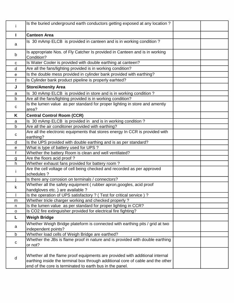
iIs the buried underground earth conductors getting exposed at any location ?
I Canteen Area
aIs 30 mAmp ELCB is provided in canteen and is in working condition ?
bIs appropriate Nos. of Fly Catcher Is provided in Canteen and is in working
Condition?
c Is Water Cooler is provided with double earthing at canteen?
d Are all the fans/lighting provided is in working condition?
e Is the double mess provided in cylinder bank provided with earthing?
f Is Cylinder bank product pipeline is properly earhted?
J Store/Amenity Area
a Is 30 mAmp ELCB is provided in store and is in working condition ?
b Are all the fans/lighting provided is in working condition?
cIs the lumen value as per standard for proper lighting in store and amentiy
area?
K Central Control Room (CCR)
a Is 30 mAmp ELCB is provided in and is in working condition ?
b Are all the air conditoner provided with earthing?
cAre all the electronic equipments that stores energy In CCR is provided with
earthing?
d Is the UPS provided with double earthing and is as per standard?
e What is type of battery used for UPS ?
f Whether the battery Room is clean and well ventilated?
g Are the floors acid proof ?
h Whether exhaust fans provided for battery room ?
iAre the cell voltage of cell being checked and recorded as per approved
schedules ?
j Is there any corrosion on terminals / connectors?
kWhether all the safety equipment ( rubber apron,googles, acid proof
handgloves etc. ) are available ?
l Is the operation of UPS satisfactory ? ( Test for critical service ) ?
m Whether tricle charger working and checked properly ?
n Is the lumen value as per standard for proper lighting in CCR?
o Is CO2 fire extinguisher provided for electrical fire fighting?
L Weigh Bridge
aWhether Weigh Bridge plateform is connected with earthing pits / grid at two
independent points?
b Whether load cells of Weigh Bridge are earthed?
cWhether the JBs is flame proof in nature and is provided with double earthing
or not?
dWhether all the flame proof equipments are provided with additional internal
earthing inside the terminal box through additional core of cable and the other
end of the core is terminated to earth bus in the panel.

e
Whether electrical light fittings are flame proof, cable connections are with
flame proof double compression glands and no armour is exposed any
where?
fThe Electronic Indicator of weigh bridge is provided with earthing or not ?
gWhether all electronic equipment which stores electrical energy are properly
earthed ?
M Tank Lorry Filling (TLF)
a
Whether electrical light fittings are flame proof, cable connections are with
flame proof double compression glands and no armor is exposed any where?
bWhether all the flame proof equipments are provided with additional internal
earthing inside the terminal box through additional core of cable and the other
end of the core is terminated to earth bus in the panel.
cWhether earthing connections, fixing and continuity of conductor with body
and junction box in the pits is OK?
dWhether bonding arrangement for Tank trucks with crocodile clips provided?
eWhether crocodile clips have lost the springing action causing improper grip
with the surface, clips are rusted?
f Whether Emerency Lights are provided and is in working condition ?
g Are all the loading arms earthed?
hWhether the flexible wire used for tankers body earthing (TTL Gantry) is
soldered to crocodile clips ?
iWhether earth jumpers across the pipe flanges (of gantry piping ) are
provided ?
jWhether all electronic equipment which stores electrical energy are properly
earthed ?
kIs the buried underground earth conductors getting exposed at any location ?
l Whether all GMS Sensors provided are properly earthed ?
N Mounded bullet/LPG pump House
a Is Cathodic Protection Log Book maintained on daily basis ?
bIs Mounded Bullet properly isolated from oulet and inlet pipelines for effective
protection
c Is reference voltage of reference cell within the limits
dIs over and under protection alarm & indicator for cahtodic protection is
provided and is working
eAre the Junction boxes of cathodic protection are flame proof and provided
with double earthing.
fIs healty and unhealthy condition status of cathodic protection is being
displayed in DCS.
g Anode current value is within the range as per OEM recommendation.
h Is lighting arrestor provided for cathodic lighting prtotection.
i Whether the motor of LPG Pump is provided with double earthing
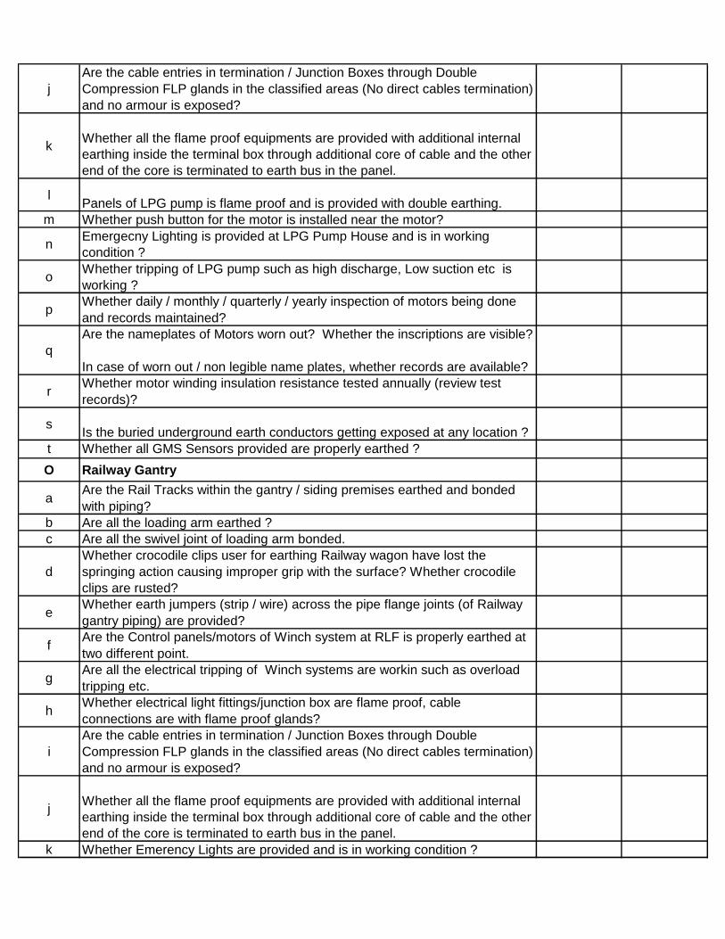
j
Are the cable entries in termination / Junction Boxes through Double
Compression FLP glands in the classified areas (No direct cables termination)
and no armour is exposed?
kWhether all the flame proof equipments are provided with additional internal
earthing inside the terminal box through additional core of cable and the other
end of the core is terminated to earth bus in the panel.
lPanels of LPG pump is flame proof and is provided with double earthing.
m Whether push button for the motor is installed near the motor?
nEmergecny Lighting is provided at LPG Pump House and is in working
condition ?
oWhether tripping of LPG pump such as high discharge, Low suction etc is
working ?
pWhether daily / monthly / quarterly / yearly inspection of motors being done
and records maintained?
q
Are the nameplates of Motors worn out? Whether the inscriptions are visible?
In case of worn out / non legible name plates, whether records are available?
rWhether motor winding insulation resistance tested annually (review test
records)?
sIs the buried underground earth conductors getting exposed at any location ?
t Whether all GMS Sensors provided are properly earthed ?
O Railway Gantry
aAre the Rail Tracks within the gantry / siding premises earthed and bonded
with piping?
b Are all the loading arm earthed ?
c Are all the swivel joint of loading arm bonded.
d
Whether crocodile clips user for earthing Railway wagon have lost the
springing action causing improper grip with the surface? Whether crocodile
clips are rusted?
eWhether earth jumpers (strip / wire) across the pipe flange joints (of Railway
gantry piping) are provided?
fAre the Control panels/motors of Winch system at RLF is properly earthed at
two different point.
gAre all the electrical tripping of Winch systems are workin such as overload
tripping etc.
hWhether electrical light fittings/junction box are flame proof, cable
connections are with flame proof glands?
i
Are the cable entries in termination / Junction Boxes through Double
Compression FLP glands in the classified areas (No direct cables termination)
and no armour is exposed?
jWhether all the flame proof equipments are provided with additional internal
earthing inside the terminal box through additional core of cable and the other
end of the core is terminated to earth bus in the panel.
k Whether Emerency Lights are provided and is in working condition ?

lWhether all electronic equipment which stores electrical energy are properly
earthed ?
mIs the buried underground earth conductors getting exposed at any location ?
n Whether all GMS Sensors provided are properly earthed ?
P Degassing Unit
aWhether the motor is provided with double earthing and is flameproof in
nature?
b Whether the coupling guard and fan guard is provided for motor?
cWheter the push buttons/junction boxes is provided with double earthing and
is flame proof in nature?
d
Are the cable entries in termination / Junction Boxes through Double
Compression FLP glands in the classified areas (No direct cables termination)
and no armour is exposed?
e Whether the screw compessor is provided with double body earthing?
f Whether the screw air compressor tripping are working?
gWhether the visual indication and annunciation is provided for respective
trippings of compressor and is in working condition?
h
Whether it is provided with flame proof lighting fixtures and is provided with
earthing?
i
Is the lumen value as per standard for proper lighting in degassing unit area?
j Is the buried underground earth conductors getting exposed at any location ?
Q Mother Tanks
aWhether the Mother Tanks are provided with double body earthing from two
different earth pits ?
bWhetther the electrical Junction boxes are flame proof in nature and provided
with double earthing ?
cWhether the Lighting Fixtures provided is Flame proof and provided with
double earthing ?
d
Are the cable entries in termination / Junction Boxes through Double
Compression FLP glands in the classified areas (No direct cables termination)
and no armour is exposed?
eWhether all the flame proof equipments are provided with additional internal
earthing inside the terminal box through additional core of cable and the other
end of the core is terminated to earth bus in the panel.
fWhether the flanges of liquid line and vapour line are bonded with GI strip for
proper electrical continuity?
g Are the steelcolum/mettalic structure/stair case properly earthed.
hIs the Lumen value is as per standard for proper lighting in boiler area and
control room ?
iWhether all electronic equipment which stores electrical energy are properly
earthed ?
j Whether all GMS Sensors provided are properly earthed ?
kIs the buried underground earth conductors getting exposed at any location ?

R Vapor Compressor House
a Is dust or dirt accumulated on motor
bWhether the motor is properly protected from dust dirt water chemical fumes
etc
c Is motor Vibration level is within permissible value
d Is there any abnormal sound in motor
eWhether the motor has been earthed properly by two separate earth
connections?
f
Are the cable entries in termination / Junction Boxes through Double
Compression FLP glands in the classified areas (No direct cables termination)
and no armour is exposed?
gAre all the Junction Boxes are of flame proof type and provided with double
earthing
hWhether all the flame proof equipments are provided with additional internal
earthing inside the terminal box through additional core of cable and the other
end of the core is terminated to earth bus in the panel.
iFor oil filled bearings, whether sufficient oil is there in bearing and check for
oil circulation.
j Is the lumen value as per standard for proper lighting?
k
Vapor Compressor Tripping such as Low Suction Pressure ,High Suction
Pressure, High Fine Oil Seprator Pressure, High discharge temperature and
others as per OEM recommendation are working
lIs the IR value of HT motor measured with 2.5 KV Megger and IR value is
equal to or above 50 M Ohms for 6.6. KV motors
mWhether electrical light fittings are flame proof, cable connections are with
flame proof glands?
n Whether Emerency Lights are provided and is in working condition ?
oWhether daily / monthly / quarterly / yearly inspection of motors being done
and records maintained?
p
Are the nameplates of Motors worn out? Whether the inscriptions are visible?
In case of worn out / non legible name plates, whether records are available?
q Are the steelcolum/mettalic structure/stair case properly earhted?
r Whether there is any discontinuity of earthing connection ?
sWhether earth jumpers across the pipe flanges (of gantry piping ) are
provided ?
tIs the buried underground earth conductors getting exposed at any location ?
uWhether earth jumpers across the pipe flanges (of gantry piping ) are
provided ?
v Whether all GMS Sensors provided are properly earthed ?
S Appartus Field System (AFS)
aWhether the receiver tank/condenser/vaporiser/heater is provided with
double body earthing as per standard?
b Are the steel colum/mettalic structure/stair case properly earhted?
cWhether the lighting fixtures is flame proof in nature and provided with
earthing?
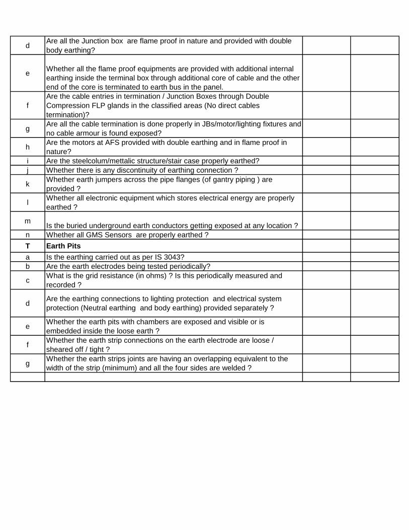
dAre all the Junction box are flame proof in nature and provided with double
body earthing?
eWhether all the flame proof equipments are provided with additional internal
earthing inside the terminal box through additional core of cable and the other
end of the core is terminated to earth bus in the panel.
f
Are the cable entries in termination / Junction Boxes through Double
Compression FLP glands in the classified areas (No direct cables
termination)?
gAre all the cable termination is done properly in JBs/motor/lighting fixtures and
no cable armour is found exposed?
hAre the motors at AFS provided with double earthing and in flame proof in
nature?
i Are the steelcolum/mettalic structure/stair case properly earthed?
j Whether there is any discontinuity of earthing connection ?
kWhether earth jumpers across the pipe flanges (of gantry piping ) are
provided ?
lWhether all electronic equipment which stores electrical energy are properly
earthed ?
mIs the buried underground earth conductors getting exposed at any location ?
n Whether all GMS Sensors are properly earthed ?
T Earth Pits
a Is the earthing carried out as per IS 3043?
b Are the earth electrodes being tested periodically?
cWhat is the grid resistance (in ohms) ? Is this periodically measured and
recorded ?
dAre the earthing connections to lighting protection and electrical system
protection (Neutral earthing and body earthing) provided separately ?
eWhether the earth pits with chambers are exposed and visible or is
embedded inside the loose earth ?
fWhether the earth strip connections on the earth electrode are loose /
sheared off / tight ?
gWhether the earth strips joints are having an overlapping equivalent to the
width of the strip (minimum) and all the four sides are welded ?

MAX. AWARD WTAGE.
1.0
1.1
1.1.1 Statutory Yearly inspection of Boilers by
Boiler Authority carried out and records
maintained.
5
1.1.2 Shortcomings identified during inspection
have been rectified before start-up
5
1.1.3 Following trips have been tested by boiler
operator and records maintained. Do sample
test of two trips during the day.
1.1.3.1 Boiler High Pressure Switch Tripping 2
1.1.3.2 Drum Level Trippings 2
1.1.3.3 Low Deisel Pressure Tripping 2
1.1.3.4 FD Fan Air Flow Tripping 2
1.1.3.5 Deaerater Level Low Trip 2
1.1.3.6 Flame Failure Trip 2
1.1.3.7 Drum Level Trippings 2
1.1.4 No leakage of following
1.1.4.1 Diesel 3
1.1.4.2 Flue Gas 3
1.1.4.3 Steam 3
1.1.5 Shift wise blowdown carried out and records
maintained
2
1.1.6 Preventive maintenance schedule prepared
and carried out and records maintained
2
1.1.7
1.1.7.1 Steam Header Pressure 2
1.1.7.2 PRDS Pressure 2
1.1.7.3 PRDS steam temperature 2
1.1.7.4 Main steam flow 2
1.1.7.5 Drum Water level 2
1.1.7.6 Feed water flow 2
1.1.7.7 LPG Control valve position 2
1.1.7.8 LPG Flow 2
1.1.7.9 LPG level controller 2
1.1.7.10 HSD Tank level alarm high and low 2
1.1.7.11 HSD Fuel pump pressure indicator 2
1.1.7.12 FD fan vent openin controller 2
TYPICAL CHECKLIST FOR REFRIGERATED LPG IMPORT TERMINAL
Maintenance and Inspection Audit Format
Sr. No. AREAYES /
NO
MARKSREMARKS
UTILITY AREA
BOILERS
Following indicators and controllers are healthy and audio visual alarms are working
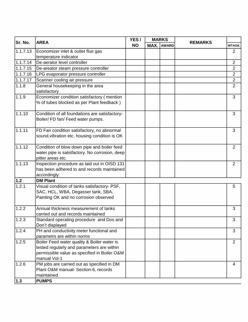
MAX. AWARD WTAGE.Sr. No. AREA
YES /
NO
MARKSREMARKS
1.1.7.13 Economizer inlet & outlet flue gas
temperature indicator
2
1.1.7.14 De-aerator level controller 2
1.1.7.15 De-areator steam pressure controller 2
1.1.7.16 LPG evaporator pressure controller 2
1.1.7.17 Scanner cooling air pressure 2
1.1.8 General housekeeping in the area
satisfactory
2
1.1.9 Economizer condition satisfactory ( mention
% of tubes blocked as per Plant feedback )
3
1.1.10 Condition of all foundations are satisfactory-
Boiler/ FD fan/ Feed water pumps.
3
1.1.11 FD Fan condition satisfactory, no abnormal
sound,vibration etc. housing condition is OK
3
1.1.12 Condition of blow down pipe and boiler feed
water pipe is satisfactory. No corrosion, deep
pitter areas etc.
2
1.1.13 Inspection procedure as laid out in OISD 131
has been adhered to and records maintained
accordingly.
2
1.2
1.2.1 Visual condition of tanks satisfactory- PSF,
SAC, HCL, WBA, Degasser tank, SBA.
Painting OK and no corrosion observed
5
1.2.2 Annual thickness measurement of tanks
carried out and records maintained
3
1.2.3 Standard operating procedure and Dos and
Don’t displayed
3
1.2.4 PH and conductivity meter functional and
parametrs are within norms
3
1.2.5 Boiler Feed water quality & Boiler water is
tested regularly and parameters are within
permissible value as specified in Boiler O&M
manual Vol-1
2
1.2.6 PM jobs are carried out as specified in DM
Plant O&M manual- Section-6, records
maintained
4
1.3
DM Plant
PUMPS
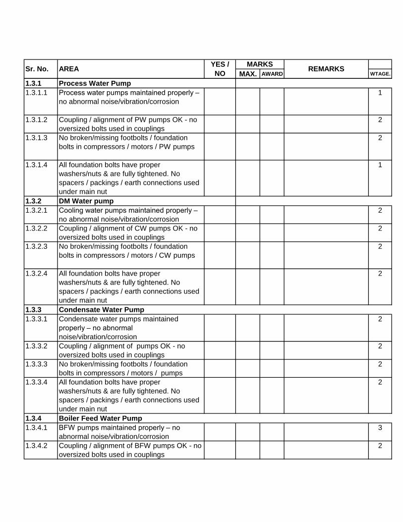
MAX. AWARD WTAGE.Sr. No. AREA
YES /
NO
MARKSREMARKS
1.3.1
1.3.1.1 Process water pumps maintained properly –
no abnormal noise/vibration/corrosion
1
1.3.1.2 Coupling / alignment of PW pumps OK - no
oversized bolts used in couplings
2
1.3.1.3 No broken/missing footbolts / foundation
bolts in compressors / motors / PW pumps
2
1.3.1.4 All foundation bolts have proper
washers/nuts & are fully tightened. No
spacers / packings / earth connections used
under main nut
1
1.3.2
1.3.2.1 Cooling water pumps maintained properly –
no abnormal noise/vibration/corrosion
2
1.3.2.2 Coupling / alignment of CW pumps OK - no
oversized bolts used in couplings
2
1.3.2.3 No broken/missing footbolts / foundation
bolts in compressors / motors / CW pumps
2
1.3.2.4 All foundation bolts have proper
washers/nuts & are fully tightened. No
spacers / packings / earth connections used
under main nut
2
1.3.3
1.3.3.1 Condensate water pumps maintained
properly – no abnormal
noise/vibration/corrosion
2
1.3.3.2 Coupling / alignment of pumps OK - no
oversized bolts used in couplings
2
1.3.3.3 No broken/missing footbolts / foundation
bolts in compressors / motors / pumps
2
1.3.3.4 All foundation bolts have proper
washers/nuts & are fully tightened. No
spacers / packings / earth connections used
under main nut
2
1.3.4
1.3.4.1 BFW pumps maintained properly – no
abnormal noise/vibration/corrosion
3
1.3.4.2 Coupling / alignment of BFW pumps OK - no
oversized bolts used in couplings
2
DM Water pump
Condensate Water Pump
Boiler Feed Water Pump
Process Water Pump
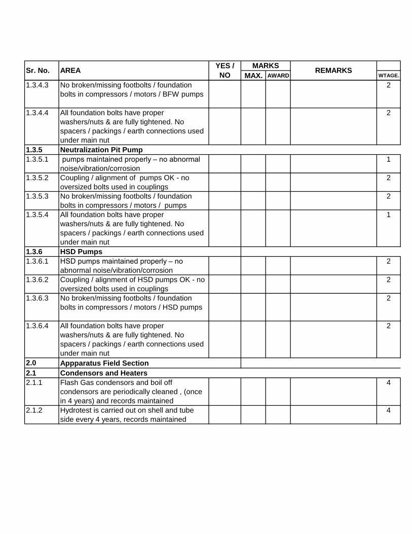
MAX. AWARD WTAGE.Sr. No. AREA
YES /
NO
MARKSREMARKS
1.3.4.3 No broken/missing footbolts / foundation
bolts in compressors / motors / BFW pumps
2
1.3.4.4 All foundation bolts have proper
washers/nuts & are fully tightened. No
spacers / packings / earth connections used
under main nut
2
1.3.5
1.3.5.1 pumps maintained properly – no abnormal
noise/vibration/corrosion
1
1.3.5.2 Coupling / alignment of pumps OK - no
oversized bolts used in couplings
2
1.3.5.3 No broken/missing footbolts / foundation
bolts in compressors / motors / pumps
2
1.3.5.4 All foundation bolts have proper
washers/nuts & are fully tightened. No
spacers / packings / earth connections used
under main nut
1
1.3.6
1.3.6.1 HSD pumps maintained properly – no
abnormal noise/vibration/corrosion
2
1.3.6.2 Coupling / alignment of HSD pumps OK - no
oversized bolts used in couplings
2
1.3.6.3 No broken/missing footbolts / foundation
bolts in compressors / motors / HSD pumps
2
1.3.6.4 All foundation bolts have proper
washers/nuts & are fully tightened. No
spacers / packings / earth connections used
under main nut
2
2.0
2.1
2.1.1 Flash Gas condensors and boil off
condensors are periodically cleaned , (once
in 4 years) and records maintained
4
2.1.2 Hydrotest is carried out on shell and tube
side every 4 years, records maintained
4
Neutralization Pit Pump
HSD Pumps
Appparatus Field Section
Condensors and Heaters

MAX. AWARD WTAGE.Sr. No. AREA
YES /
NO
MARKSREMARKS
2.1.3 Condensate receiver vessel in good
condition. Testing not over due. Records of
periodic testing and hydrotest maintained.
Flash Gas Condensate Receiver is to be
tested as per SMPV Rules 1981 ( unfired)
3
2.1.4 Annual test of Boil -off condensate receiver
vessel SRV carried out and records
maintained
2
2.1.5 Receiver discharge pumps are in helathy
condition. No abnormal sound, Vibration.
2
2.1.6 Flow controllers FC70 & 70B for receiver
discharge Pumps are in Auto mode and not
in manual
2
2.1.7 Four yearly cleaning and hydrotest of LPG
heaters carried out and records maintained
2
2.1.8 LPG heaters are in good condition. Painting
is OK and no corrosion
3
2.1.9 No leakage of Steam, LPG from exchangers
or pipes
2
2.1.10 Piping condition is satisfactory, painting, no
corrosion, pipe supports.
3
2.1.11 Structurals are in good condition, painting
ok, no corrosion, No loose foundation bolts
etc.
3
2.1.12 Pipes are easily identified with proper colour
codes
2
2.2
2.2.1 Control Valves are functional and calibrated. 2
2.2.2 No leakage of Mercaptan from tank or pipes
or pumps
2
2.2.3 Dosing pump is operational and dosing is
under auto control
3
2.2.4 Flow meters are functional and transmitters
are calibrated quarterly
2
2.2.5 Mercaptan is properly stored and no spillage
is observed
2
2.2.6 Pressure and temperature gauges are
working and claibrations are done
2
Blending Section

MAX. AWARD WTAGE.Sr. No. AREA
YES /
NO
MARKSREMARKS
2.2.7 Vapour Pressure Analyser is functional and
online
4
2.2.8 Housekeeping in the area is satisfactory 2
2.2.9 Pipeline condition is satisfactory- Painting,
no corrosion
2
3.0
Hoses used are of approved quality
standards (IS 9573)
OR
Unloading arms are free & easy to operate,
quick couplings in good working condition
3.0.2 Loading hoses when not in use are stored
properly & open end kept blinded [O] /
Female coupling kept covered with
plastic/rubber caps.
3
3.0.3 No loading / unloading hoses having kinks /
cracks
2
3.0.4 Hoses periodically tested and test records
available
2
3.0.5 Studs & gaskets used for connecting with
tankers are of acceptable quality
2
3.0.6 All quick shutoff valves / ROVs of TLD
functioning properly
2
3.0.7 Unloading arms – PM schedules followed &
records maintained
2
3.0.8 Interlocking system of female coupling with
male coupling is OK in all unloading arms -
not tied with ropes/wires
2
3.0.9 Foundation bolts & other bolts of unloading
arms are properly tightened
2
3.0.10 Earthing wires of swivel joints / unloading
arms are OK & not broken
2
3.0.11 All Balancing devices are operational 2
3.0.12 Swivel joints are operational without any
leaks
2
3.0.13 No visible external damages on unloading
arms
2
3.0.14 Unloading arms central column and brackets
not damaged / corroded
2
3.0.15 Gantry structurals in good condition –
painting in good condition
2
3.0.1 3
TLF / WEIGHBRIDGE
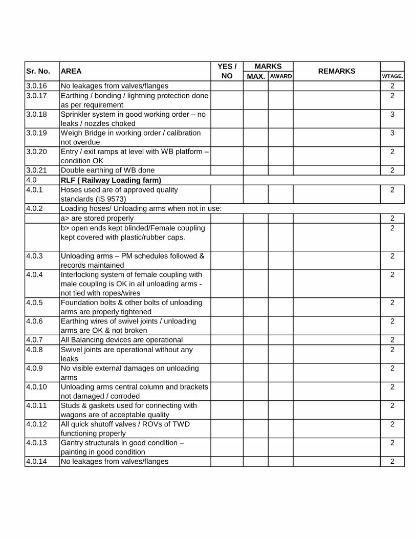
MAX. AWARD WTAGE.Sr. No. AREA
YES /
NO
MARKSREMARKS
3.0.16 No leakages from valves/flanges 2
3.0.17 Earthing / bonding / lightning protection done
as per requirement
2
3.0.18 Sprinkler system in good working order – no
leaks / nozzles choked
3
3.0.19 Weigh Bridge in working order / calibration
not overdue
3
3.0.20 Entry / exit ramps at level with WB platform –
condition OK
2
3.0.21 Double earthing of WB done 2
4.0
4.0.1 Hoses used are of approved quality
standards (IS 9573)
2
4.0.2
a> are stored properly 2
b> open ends kept blinded/Female coupling
kept covered with plastic/rubber caps.
2
4.0.3 Unloading arms – PM schedules followed &
records maintained
2
4.0.4 Interlocking system of female coupling with
male coupling is OK in all unloading arms -
not tied with ropes/wires
2
4.0.5 Foundation bolts & other bolts of unloading
arms are properly tightened
2
4.0.6 Earthing wires of swivel joints / unloading
arms are OK & not broken
2
4.0.7 All Balancing devices are operational 2
4.0.8 Swivel joints are operational without any
leaks
2
4.0.9 No visible external damages on unloading
arms
2
4.0.10 Unloading arms central column and brackets
not damaged / corroded
2
4.0.11 Studs & gaskets used for connecting with
wagons are of acceptable quality
2
4.0.12 All quick shutoff valves / ROVs of TWD
functioning properly
2
4.0.13 Gantry structurals in good condition –
painting in good condition
2
4.0.14 No leakages from valves/flanges 2
RLF ( Railway Loading farm)
Loading hoses/ Unloading arms when not in use:

MAX. AWARD WTAGE.Sr. No. AREA
YES /
NO
MARKSREMARKS
4.0.15 Earthing / bonding / lightning protection done
as per requirement
2
4.0.16 Winch for wagons are tested and records
available
2
4.0.17 Mass flow meters are functional and
calibrated. Calibration certificates are valid
2
4.0.18 Sprinkler system in good working order – no
leaks / nozzles choked
2
4.0.19 In-motion Weigh Bridge in working order /
calibration not overdue
3
4.0.20 Double earthing of WB done 2
5.0
5.1
5.1.1
a> Whether inspection / test certificates at
the time of original fabrication available
(including drawing and certificates
mentioning NDT inspection) [O]
5
5.1.2 All SRVs are tested annually / tests are not
overdue [O]
2
5.1.3 SRVs are provided with vent pipes 2
5.1.4 SRVs are provided with isolation valves &
locked [O]
2
5.1.5 insulation periodically checked for damage/,
bulging & suspect areas are further
inspected for presence of corrosion, etc., &
corrective steps taken
4
5.1.6 Auto Flare valve opening at 1000mm WC is
functional and tested
2
5.1.7 Earthing connections properly maintained
[O]
3
5.1.8 Condition of grounding electrodes OK [O] 3
5.1.9 Pipeline insulation condition is OK. No
portion exposed
2
5.1.10 No portion of pipe length found buried with
soil or undergrowth
3
5.1.11 Bolts on flanges are properly sized / no bolts
missing
2
5.1.12 No leakages from valves glands 3
5.1.13 Caps provided over Pop action valves 5
ATMOSPHERIC REFRIGERATED BUTANE/PROPANE TANKS
Following records were available and found valid:
BULK STORAGE AREA

MAX. AWARD WTAGE.Sr. No. AREA
YES /
NO
MARKSREMARKS
5.1.14 Condition of paint of Vessel cladding and
roof acceptable for 1 more year - no large
corroded areas
3
5.1.15 Condition of structurals, ladders, railings,
platforms OK
3
5.1.16 Pressure / Temperature gauges and
transmitters OK
2
5.1.17 Both the level gauges are functional and
there is no abnormal variation in their
readings
2
5.1.18 Sprinkler system OK – no leaks / choked
nozzles
4
5.2
5.2.1
5.2.2 Vibration Readings. 4
5.2.3 Discharge Flow rate 4
5.2.4 Motor Current drawn 4
5.2.5 Discharge pressure 4
5.2.6 Following trips are functional
5.2.6.1 Interlock tripping for : Pressure 4
5.2.6.2 Interlock tripping for : Flow rate 4
5.2.6.3 Interlock tripping for : motor current 4
5.3 MOUNDED LPG TANKS ( BUFFER
TANKS)
5.3.1 Condition of mound OK. No cracks /
seepage
3
5.3.2 Overall condition of Cathodic Protection
system (cabling / JBs / surge protectors, etc.)
OK
2
5.3.3 Six monthly settlment reading is being taken
and recorded. Reference level is identified
and marked.
3
5.3.4 CP panel and meters in proper working
condition
2
5.3.5 All CP voltages are as per requirement
(records to be checked)
3
5.3.6 Sprinkler system OK – no leaks / choked
nozzles
2
5.3.7 ROVs of bulk storage areas operate within
acceptable response time (max. 30 secs.)
2
Intank LPG Pumps
Following operating parameters within permissible

MAX. AWARD WTAGE.Sr. No. AREA
YES /
NO
MARKSREMARKS
6.0 PIPELINES / VALVES
6.1 PIPELINES – A/G & U/G
6.1.1 Inspection records of annual / 5-year testing
of underground / aboveground LPG lines [O]
2
6.1.2 Pipe supports are not damaged – point
contact & properly spaced
2
6.1.3 No vegetation growth below pipelines or
concreting / brick pitching done below
pipelines
2
6.1.4 Pipelines crossing roads/ dykes are wrapped
& coated - visible portions are OK
2
6.1.5 Piping culverts are clean & pipe painting OK 2
6.1.6 Pipe surfaces are free from deep pitting
corrosion & large pitted areas
3
6.1.7 Pipeline painting/Insulation is free from
defects and corrosion spots
4
6.1.8 No voids / peeling in wrapping-coating on
portions of lines emerging from ground at
road crossings
3
6.1.9 NDT of pipelines carried out as per HO LPG
(M&I) guidelines in the last 3 years & reports
available
3
6.1.10 Continuity of Earthing / Bonding in LPG
pipelines maintained
2
6.1.11 All pop-action valves are OK (properly set &
not passing) & their isolation valves are kept
open
2
6.1.12 Flange joints have proper studs/nuts & are
leak free
2
6.1.13 Re-circulation line provided from farthest
points in the FW network back to the FW
tanks OR schedule for flushing of FW lines
being followed
2
6.1.14 F/W monitors / hydrants brick pitched &
provided with platforms
2
6.2 VALVES
6.2.1 Valve gland / gasket leaks attended regularly
– no leaks observed
3

MAX. AWARD WTAGE.Sr. No. AREA
YES /
NO
MARKSREMARKS
6.2.2 Isolation valves with drains for pressure
gauges / switches provided
3
6.2.3 Valve bodies are properly painted – no
excessive corrosion
3
6.2.4 Preventive maintenance followed - Greasing
of valve stems and wheel bushes done
2
6.2.5 No bent / damaged valve stems, missing
wheels found
3
6.2.6 Drain valves & vent valves are not passing &
are capped
3
6.3
6.3.1 Condition of pipelines are good and properly
painted – no excessive corrosion
2
6.3.2 Pipe supports are OK (no pipe sagging) & in
good condition
2
6.3.3 No leaks observed 3
7.0 COMPRESSORS - LPG
7.0.1 No lekage from Mechanical seal 2
7.0.2 Oil level in gear box is OK 3
7.0.3 Noise / vibration levels of compressors /
motors.gear box are satisfactory
2
7.0.4 Condition of coupling & alignment OK 2
7.0.5 Coupling guards in position - rigid 2
7.0.6 Earthing connections properly maintained –
not connected to footbolts
1
7.0.7 Painting / cleaning of body OK / no oil
spillage
2
7.0.8 Oil level in Oil drum is sufficient & quality OK
( to be checked in Off- condition )
2
7.0.9 discharg gas temperatures within limits 2
7.0.10 Differential pressure between lubeoil and
LPG vapour is within acceptable limits
3
7.0.11 Preventive maintenance schedules followed
& records maintained
3
7.0.12 All tripping devices are healthy ( discharge
pressure , low suction pressure, low lube-
vapour differential, low lube level, high gas
dischage temp, low lube temperature,) 32
deg C ), High Lube temp ( 60 deg C )
3
SERVICE / SECURITY AIR , WATER & STEAM LINES
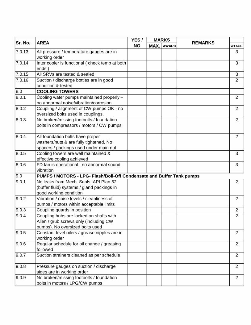
MAX. AWARD WTAGE.Sr. No. AREA
YES /
NO
MARKSREMARKS
7.0.13 All pressure / temperature gauges are in
working order
3
7.0.14 Inter cooler is functional ( check temp at both
ends )
3
7.0.15 All SRVs are tested & sealed 3
7.0.16 Suction / discharge bottles are in good
condition & tested
2
8.0 COOLING TOWERS
8.0.1 Cooling water pumps maintained properly –
no abnormal noise/vibration/corrosion
2
8.0.2 Coupling / alignment of CW pumps OK - no
oversized bolts used in couplings.
2
8.0.3 No broken/missing footbolts / foundation
bolts in compressors / motors / CW pumps
2
8.0.4 All foundation bolts have proper
washers/nuts & are fully tightened. No
spacers / packings used under main nut
2
8.0.5 Cooling towers are well maintained &
effective cooling achieved
3
8.0.6 FD fan is operational , no abnormal sound,
vibration
3
9.0
9.0.1 No leaks from Mech. Seals. API Plan 52
(buffer fluid) systems / gland packings in
good working condition
2
9.0.2 Vibration / noise levels / cleanliness of
pumps / motors within acceptable limits
2
9.0.3 Coupling guards in position 2
9.0.4 Coupling hubs are locked on shafts with
Allen / grub screws only (including CW
pumps). No oversized bolts used
2
9.0.5 Constant level oilers / grease nipples are in
working order
2
9.0.6 Regular schedule for oil change / greasing
followed
2
9.0.7 Suction strainers cleaned as per schedule 2
9.0.8 Pressure gauges on suction / discharge
sides are in working order
2
9.0.9 No broken/missing footbolts / foundation
bolts in motors / LPG/CW pumps
2
PUMPS / MOTORS - LPG- Flash/Boil-Off Condensate and Buffer Tank pumps

MAX. AWARD WTAGE.Sr. No. AREA
YES /
NO
MARKSREMARKS
9.0.10 All foundation bolts have proper
washers/nuts & are fully tightened. No
spacers / packings / earth connections used
under main nuts
2
9.0.11 Shims / packings used for alignment are of
Brass / SS only & of proper shape & size
2
9.0.12 Breathers / Vents of bearing housings are as
per requirement & kept clean
2
9.0.13 No oil/water spillage on base frames 4
9.0.14 Bearing / lube oil temperatures within limits 3
9.0.15 Condition of base frames OK (painting pitting
/ corrosion, etc.) - no water logging
2
9.0.16 Preventive maintenance schedule of pumps
implemented, followed & recorded
3
9.0.17 Preventive maintenance schedule of motors
implemented, followed & recorded
3
9.0.18 Pipe manifolds / valves (no leaks) / fittings
well maintained and painted
2
9.0.19 Servo gauges / Level gauges / alarms in
working order
2
10.0 FPH / ACH
10.1 COMPRESSORS - AIR
10.1.1 Stuffing box leakage not excessive 3
10.1.2 Noise / vibration levels of compressors /
motors are satisfactory
3
10.1.3 Condition of belts / pulleys & alignment OK 2
10.1.4 Coupling guards in position - rigid 3
10.1.5 Painting / cleaning of body OK / no oil
spillage
2
10.1.6 Oil level in sump is sufficient & quality OK
(no frothing)
3
10.1.7 Discharge air temperatures within limits 2
10.1.8 Lubricating oil pressure is proper 3
10.1.9 Preventive maintenance schedules followed
& records maintained
3
10.1.10 All tripping devices are healthy 2

MAX. AWARD WTAGE.Sr. No. AREA
YES /
NO
MARKSREMARKS
10.1.11 All pr./temp. gauges are in working order.
Calibration not overdue
3
10.1.12 All SRVs are tested & sealed 2
10.1.13 All Cooling water passages including gland
cooling are clear with proper flow
3
10.1.14 Cooling water pumps maintained properly –
no abnormal noise/vibration/corrosion
2
10.1.15 Coupling / alignment of CW pumps OK - no
oversized bolts used in couplings
2
10.1.16 No broken/missing footbolts / foundation
bolts in compressors / motors / CW pumps
2
10.1.17 All foundation bolts have proper
washers/nuts & are fully tightened. No
spacers / packings / earth connections used
under main nut
2
10.1.18 Aftercoolers are in good condition - no
overheating of shell
2
10.1.19 Air receiver vessels are in good condition -
no corrosion / proper paint & supports /
testing not overdue
2
10.1.20 Cooling towers are well maintained &
effective cooling achieved
2
10.1.21 Frequency of starting of Security Air
Compressor is more than 30 minutes
2
10.2 AIR DRIER
10.2.1 Air dryer in proper working condition. 2
10.2.2 PM schedules followed & recorded - all filters
cleaned / valves serviced
2
10.2.3 Dew point test done in last 6 months &
record available
2
10.2.4 Air pressure at inlet / outlet OK 1
10.2.5 All SRVs are tested & sealed 2
10.2.6 Buffer vessels drained of condensate 2
10.3
10.3.1 No excessive leaks from glands - packings
in good working condition
2
10.3.2 Gland plates are not overtightened - no
smoke from glands during pump running
2
10.3.3 All bearing housing bolts are tight - no bolts
missing
2
PUMPS / ENGINES / MOTORS - WATER

MAX. AWARD WTAGE.Sr. No. AREA
YES /
NO
MARKSREMARKS
10.3.4 Vibration / noise levels / cleanliness of
pumps / motors / engines are satisfactory
2
10.3.5 Coupling guards in position 2
10.3.6 Constant level oilers / grease nipples are in
working order
2
10.3.7 Regular schedule for oil change / greasing
followed
2
10.3.8 Pump suction strainers / engine air filters
cleaned as per schedule
5
10.3.9 Pressure gauges on suction / discharge
sides are in working order.
3
10.3.10 All gauges in engines are working accurately 2
10.3.11 All audio-visual alarms of fire engines are
operating
2
10.3.12 All foundation bolts have proper
washers/nuts & are fully tightened. No
spacers / packings / earth connections used
under main nut
1
10.3.13 Shims / packings used for alignment are of
Brass / SS only & are of proper shape & size
3
10.3.14 Breathers / Vents of bearing housings are as
per requirement & kept clean
1
10.3.15 All drive belts are in good condition - proper
tension / no cracks / not worn out
3
10.3.16 Coupling hubs are locked on shafts with
Allen / grub screws (CW / Jockey pumps).
No oversized bolts used
3
10.3.17 No oil/water spillage on base frames 2
10.3.18 Bearing / lube oil temperatures are within
limits.
2
10.3.19 Condition of base frames OK (painting /
pitting / corrosion, etc.) - no water logging
takes place
3
10.3.20 Preventive maintenance schedule of pumps
are implemented, followed and recorded
2
10.3.21 Preventive maintenance schedule of motors
/ diesel engines implemented, followed &
recorded
3

MAX. AWARD WTAGE.Sr. No. AREA
YES /
NO
MARKSREMARKS
10.3.22 Fire Engine exhaust lines are properly
supported.
2
10.3.23 Fire engines’ batteries and charger in good
working condition
2
10.3.24 Diesel tanks OK (breather, LG, covers, etc.),
piping & hoses OK
2
10.3.25 Cooling water / coolant flow in engines OK &
temperatures normal
2
10.3.26 Pipe manifolds / valves (no leaks) / fittings
well maintained and painted
2
10.3.27 Coolant quality is checked regularly -
sufficient kits are available.
2
10.3.28 Frequency of starting of Jockey pump is
more than 30 minutes
2
10.4
10.4.1 Foundation-tank pad: No cracks, no
excessive settlement; proper slope
2
10.4.2 No voids between tank pad & annular plates
– no grass growth from below the plates
2
10.4.3 Annular plate is exposed & painted and not
covered by debris / vegetation
2
10.4.4 Inlet and outlet lines properly supported 2
10.4.5 No excessive undulations / buckling on the
shell / roof
2
10.4.6 Roof & shell properly painted – condition
acceptable for 1 more year
2
10.4.7 No leaky conditions in shell courses 3
10.4.8 Ladders / platforms are in good condition,
safe & not corroded (painted)
2
10.4.9 Wind girders / roof hand rails are painted 2
10.4.10 Level gauges in working condition 2
10.4.11 Tank outlet valve in good working condition –
preventive maintenance done
3
10.4.12 Piping manifold supports are in good
condition – no damages / cracks
2
10.4.13 Common strainers, if provided, is cleaned as
per schedule
2
10.4.14 Roof vents (goosenecks) are adequate and
covered with wire mesh
2
10.4.15 Tanks are not over-filled – no overflow water
marks on roofs
3
WATER TANKS- Fire Water, DM Water, Steam Condensate

MAX. AWARD WTAGE.Sr. No. AREA
YES /
NO
MARKSREMARKS
10.4.16 Tank cleaning & internal inspection done in
last 5 years
3
10.4.17 Thickness survey carried out in last 3 years
as per HO LPG-M&I guidelines. Report
available
2
11.0 DG ROOM / PMCC
11.1 DG SETS
11.1.1 All trips / alarms (high water temp, low lube
oil pressure, over speed) are healthy
2
11.1.2 No Oil spillage on base frame of DG sets 2
11.1.3 Vibration / noise levels / cleanliness of
generators / engines are satisfactory
2
11.1.4 Coupling guards in position 2
11.1.5 Insulation provided upto silencer 2
11.1.6 Condition of radiators / heat exchangers – no
excessive fin damage / leakages / scaling
2
11.1.7 Diesel tanks OK (breather, LG, covers, etc.),
piping & hoses OK
1
11.1.8 Coolant in engines OK & temperatures
normal
1
11.1.9 Coolant quality is checked regularly -
sufficient kits are available.
2
11.1.10 Condition of diesel & coolant hoses good 3
11.1.11 All drive belts are in good condition - proper
tension / no cracks / not worn out
2
11.1.12 No excessive smoke in exhaust 3
11.1.13 Exhaust lines are properly supported 3
11.1.14 Baseframes & vibration dampers / foot bolts
in good condition
2
11.1.15 Engines’ batteries and charger in good
working condition
3
11.1.16 Panels are well maintained – all meters /
audio/visual alarms / trips annunciations are
functional
3
11.1.17 Preventive maintenance schedule of
generators / engines followed & recorded
2
11.2
11.2.1 Earth strips connected to electrodes by
electro-galvanized bolts / bolts not rusted.
Earthing pits' condition OK & as per HO LPG-
ENGG guidelines [O]
1
ELECTRICALS –PMCC / LIGHTING / MOTORS

MAX. AWARD WTAGE.Sr. No. AREA
YES /
NO
MARKSREMARKS
11.2.2 MCC Panel condition [O]:
a> Doors okay & closed 3
b> Dust / soot / cobwebs not existing 3
c> Visual condition of switch contact, fuse,
etc., OK
2
d> Control wiring condition satisfactory 2
e> Grounding okay 3
11.2.3 Condition of cable/duct [O]:
a> Cables are on rack 2
b> Cable ducts are clean 2
c> Sealing of ducts / panels OK 2
d> Cable identification tags are fixed 2
11.2.4 Condition of transformer [O]
a> Grounding OK 2
b> No oil leaks 2
c> Silica Gel OK 2
d> Oil level OK 2
e> Terminal box earthing OK 2
f> Oil / winding temperatures OK 2
g> Periodic oil quality test conducted 2
11.2.5 a> Earthing of fixtures proper [O] 2
b> Condition of wiring good [O] 2
c> Water does not enter & accumulate in
fixtures / distribution boxes etc. [O]
2
11.2.6 FLP property of fixtures:
a> No Allen bolts missing & all are tight 2
b> Cable gland proper 1
c> No unplugged openings observed 2
11.2.7 Lighting DBs, switches, MCBs, etc., well
maintained [O]
3
11.2.8 Tower / Mast Lights (Area Lighting) [O]
a> Grounding of mast OK 2
b> Condition of JBs, switch boards, fuses,
etc., OK
2
c> Approach to electrical installation &
ladders good & safe
2
11.2.9 Ground resistance at motor / push buttons
measured & found OK. [O]
1
11.2.10 a> Terminal boxes/glands/push buttons,
etc.,& their FLP properties OK. [O]
1

MAX. AWARD WTAGE.Sr. No. AREA
YES /
NO
MARKSREMARKS
11.2.11 b> Existing cable terminations are proper [O] 1
11.2.12 All fuses are of proper type & rating as
specified in single line diagram. [O]
2
11.2.13 Emergency lighting system in order [O] 3
11.2.14 Transformer maintenance carried out as per
schedule (oil change / oil filtering / check
dielectric strength)
2
11.2.15 Condition of flameproof / “Ex” equipment in
licensed area is good
2
11.2.16 Cable insulation resistance between phases
and phase to earth checked (at least once in
2 years)
2
11.2.17 Servicing of motors done as per schedule
(megger test / PM jobs)
2
11.2.18 Calibration of protective relays – done as per
schedule
2
11.2.19 Sub station wiring & terminations are neatly
done. No loose wires. Panels sealed. Cable
glands & tags OK
2
11.2.20 All light points are in working condition; glass
covers are clean
3
11.2.21 Ammeters & Voltmeters provided in motor
starters are in working condition
2
11.2.22 All telephones & intercom systems are in
working order
2
11.2.23 PM schedules for all electrical eqpt exists
and are strictly followed – records available.
2
11.2.24 Lighting towers / poles are painted properly 2
11.2.25 Condition of capacitor bank and power factor
controller OK
2
11.2.26 UPS / batteries / chargers in working
condition
2
12.0
12.0.1 Sprinkler system working satisfactorily in:
a> All sheds (empty / filling / filled / CR) 2
b> LPG pumphouse 2
12.0.2 GMS sensors are quarterly calibrated & in
working condition
2
GMS / ILSD / SPRINKLER SYSTEM / PA PAGING / WIRELESS COMMUNICATIONS

MAX. AWARD WTAGE.Sr. No. AREA
YES /
NO
MARKSREMARKS
12.0.3 All GMS sensors are healthy & in good
condition – provided with canopies.
3
12.0.4 GMS panel / mimic panels in good working
condition
3
12.0.5 GMS PC - printer interface OK; logs being
maintained
3
12.0.6 ILSD system logic OK (as per OISD 144
Cl.11.11)
3
12.0.7 Fire fighting / MCP panels / push buttons /
siren are operating satisfactorily – all audio-
visual alarms are healthy
3
12.0.8 PA / wireless communication systems in
good working order-all stations can be
contacted
3
13.0
13.1 BUILDINGS / SHEDS
13.2 Periodic painting / distempering of buildings
done
3
13.3 General maint. & cleanliness of buildings /
structurals / sheds / DV chambers etc., is
good
3
13.4 Canteen building maintenance and facilities
are satisfactory
3
13.5 No excessive cracks / water seepage in any
of the buildings
3
13.6 Shed structurals are in good condition 3
13.7 Spaceframe structures in sheds in good
condition – no sagging / bending / broken
structures/bolts
3
13.8 Sheds roofing sheets are in good condition –
no damages / leaks
3
13.9 Mastic flooring in sheds /columns OK – no
gaps / discontinuities
3
13.10 Trench drains in sheds are clean – no
choking / accumulation of water
3
13.11 General maint. of fans / lights / electricals in
buildings – MCBs / ELCBs as per norms
3
13.12 Exhaust fans working in battery room /
urinals / lavatories / bathrooms
2
13.13 Flush system / plumbing in lavatory are
working properly
3
BUILDINGS / SHEDS / ROADS / DRAINS / HOUSEKEEPING
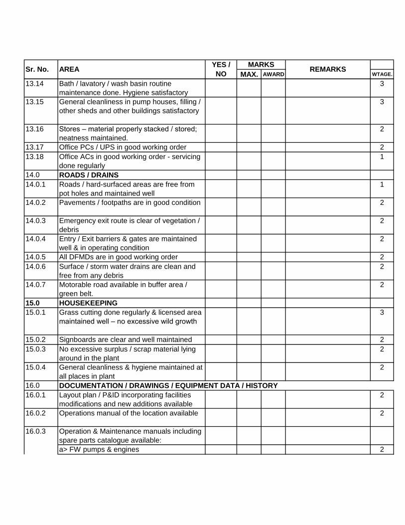
MAX. AWARD WTAGE.Sr. No. AREA
YES /
NO
MARKSREMARKS
13.14 Bath / lavatory / wash basin routine
maintenance done. Hygiene satisfactory
3
13.15 General cleanliness in pump houses, filling /
other sheds and other buildings satisfactory
3
13.16 Stores – material properly stacked / stored;
neatness maintained.
2
13.17 Office PCs / UPS in good working order 2
13.18 Office ACs in good working order - servicing
done regularly
1
14.0 ROADS / DRAINS
14.0.1 Roads / hard-surfaced areas are free from
pot holes and maintained well
1
14.0.2 Pavements / footpaths are in good condition 2
14.0.3 Emergency exit route is clear of vegetation /
debris
2
14.0.4 Entry / Exit barriers & gates are maintained
well & in operating condition
2
14.0.5 All DFMDs are in good working order 2
14.0.6 Surface / storm water drains are clean and
free from any debris
2
14.0.7 Motorable road available in buffer area /
green belt.
2
15.0 HOUSEKEEPING
15.0.1 Grass cutting done regularly & licensed area
maintained well – no excessive wild growth
3
15.0.2 Signboards are clear and well maintained 2
15.0.3 No excessive surplus / scrap material lying
around in the plant
2
15.0.4 General cleanliness & hygiene maintained at
all places in plant
2
16.0
16.0.1 Layout plan / P&ID incorporating facilities
modifications and new additions available
2
16.0.2 Operations manual of the location available 2
Operation & Maintenance manuals including
spare parts catalogue available:
a> FW pumps & engines 2
DOCUMENTATION / DRAWINGS / EQUIPMENT DATA / HISTORY
16.0.3

MAX. AWARD WTAGE.Sr. No. AREA
YES /
NO
MARKSREMARKS
b> LPG pumps- Intank, Buffer
tank,Condensate flash&Boil-off
2
c> LPG compressors- Flash & Boil-Off 2
d> Air compressors 2
e> Security air compressor 2
f> Air dryer 2
g> DG sets 2
h> Jockey pump 2
i> Boilers 2
j> LPG Analyser 2
k> CCR- DCS System 2
l> Electrical eqpt (transformer, breakers,
panels, etc.)
2
m> Weighbridge 2
n> GMS system 2
o> ROVs 2
p> Major instruments (Servogauge / DP level
gauge / Radar gauge / Transmitters /
Rochester gauge / Magnetic gauge, etc.)
2
q> DM Plant 2
16.0.4Construction / fabrication drawings of FW
tanks
2
16.0.5Fire water network as-built dimensional
fabrication drawings exist
2
16.0.6LPG piping as-built dimensional drawings
exist
2
16.0.7Layout drawings of cabling, lighting, earthing
are available
2
16.0.8Equipment Data Cards (in SAP or as per
OISD 127/128)
2
16.0.9Equipment History Cards (in SAP or as per
OISD 127/128)
2
Following manuals / documents available:
[O]
a> SMPV Rules, 1981 2
b> Relevant BIS standards 2
c> M&I Painting Manual (recommendations)
available
2
16.0.3
16.0.10

MAX. AWARD WTAGE.Sr. No. AREA
YES /
NO
MARKSREMARKS
Equipment running hours meters(totalizers)
maintained in working order & hours are
logged:
a> DG sets 2
b> Fire engines (electrical totalizers) 2
c> LPG compressors 2
d> LPG pumps 2
e> Air compressors 2
17.0 DCS System
17.0.1AMC exists with OEM for preventive
maintenance and is valid
4
17.0.2
Backup of DCS files have been taken during
AMC, record date of last data backup.
4
17.0.3
Earthing system / connections for DCS
cabinet properly maintained and values are
within permissible limits
2
17.0.4Cooling / room temperature maintained
within limits
2
17.0.5Fire fighting system provided and is in
working condition
4
18.0
18.0.1Functional locations are created for all
equipment
2
18.0.2 BOM created for all functional locations 2
18.0.3
PM tasklists prepared for all equipment as
per HO LPG-M&I guidelines, OEM & OISD
requirements
2
18.0.4 PM scheduling being carried out 2
18.0.5
Equipment data maintained in SAP in
equipment “class” & “characteristics” fields
2
18.0.6
All types of Maintenance orders (breakdown
/ shutdown / normal etc.) being routed thru
SAP PMM (check for last 3 months)
2
19.0 VIBRATION MONITORING
19.0.1
Safe base vibration limits identified for each
rotary equipment (vibration analysis done)
2
19.0.2
Corrective actions taken as per
recommendations of vibration analysis
2
SAP PLANT MAINTENANCE MODULE IMPLEMENTATION
16.0.11

MAX. AWARD WTAGE.Sr. No. AREA
YES /
NO
MARKSREMARKS
19.0.3
Vibration meter is available at plant and is in
working condition
2
19.0.4
Vibration monitoring schedule prepared &
adhered to (weekly basis for
LPG/FW/Jockey pumps / DG sets / CW
pumps / Compressors)
2
20.0 BREAKDOWNS
20.0.1 No major equipment breakdowns in last 1
year (includes LPG pumps/motors; Air
compressors / motors; FW pumps / engines;
Jockey pumpsets; DG sets; Carousel;
Vapour Extraction Blowers; Checkscales;
AVTS; VLD; BLD; O-rLD; Purging unit;
Evacuation unit; IWCU; Hot air sealing unit;
Transformers; VCB/ACB). Assign (–3) marks
for each additional breakdown if more than 2
4
TOTAL 0
WEIGHTED MAXIMUM MARKS =
0
WEIGHTED AWARDED MARKS =
0
M&I INDEX = #DIV/0!
SIGNATURES OF M.D.T. MEMBERS /
LOCATION-IN-CHARGE
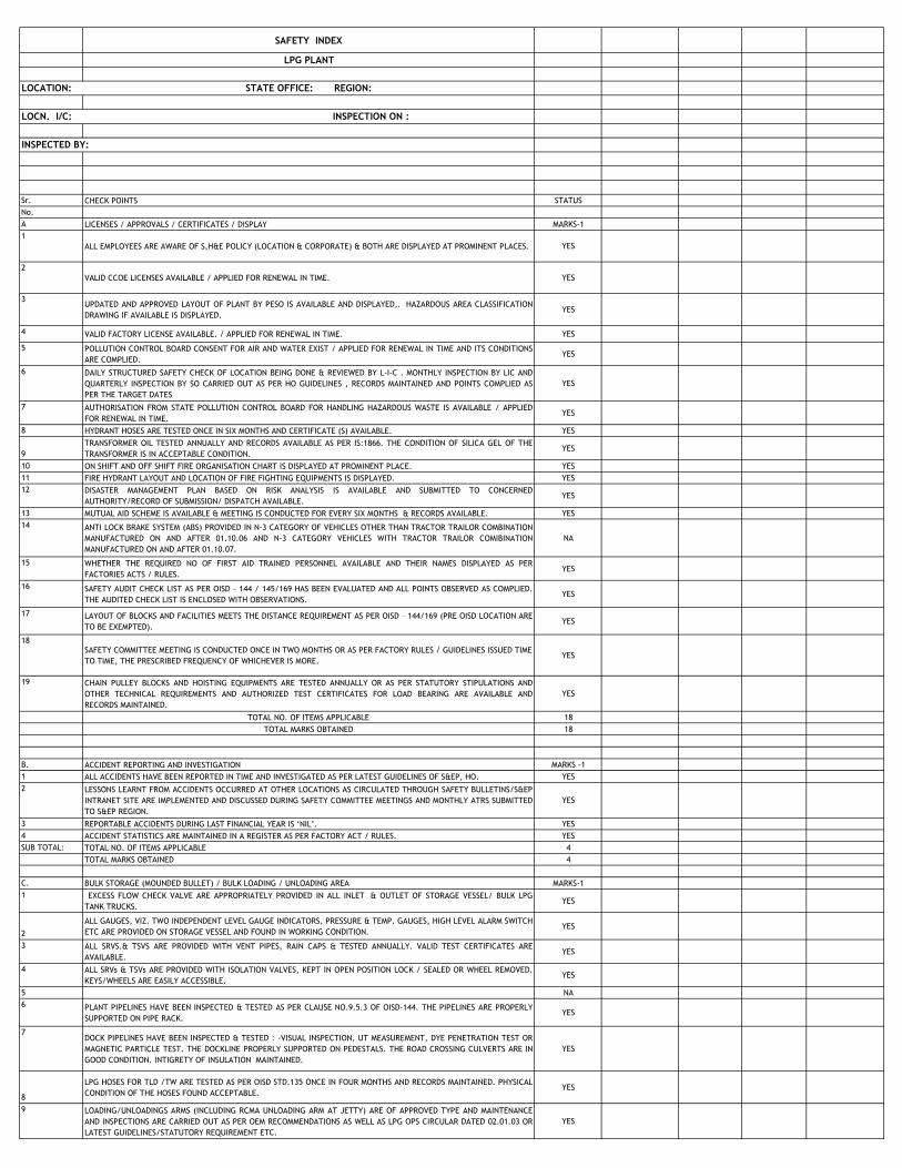
SAFETY INDEX
LPG PLANT
LOCATION: STATE OFFICE: REGION:
LOCN. I/C: INSPECTION ON :
INSPECTED BY:
Sr. CHECK POINTS STATUS
No.
A LICENSES / APPROVALS / CERTIFICATES / DISPLAY MARKS-1
1
ALL EMPLOYEES ARE AWARE OF S,H&E POLICY (LOCATION & CORPORATE) & BOTH ARE DISPLAYED AT PROMINENT PLACES. YES
2
VALID CCOE LICENSES AVAILABLE / APPLIED FOR RENEWAL IN TIME. YES
3UPDATED AND APPROVED LAYOUT OF PLANT BY PESO IS AVAILABLE AND DISPLAYED,. HAZARDOUS AREA CLASSIFICATION
DRAWING IF AVAILABLE IS DISPLAYED.YES
4 VALID FACTORY LICENSE AVAILABLE. / APPLIED FOR RENEWAL IN TIME. YES
5 POLLUTION CONTROL BOARD CONSENT FOR AIR AND WATER EXIST / APPLIED FOR RENEWAL IN TIME AND ITS CONDITIONS
ARE COMPLIED. YES
6 DAILY STRUCTURED SAFETY CHECK OF LOCATION BEING DONE & REVIEWED BY L-I-C . MONTHLY INSPECTION BY LIC AND
QUARTERLY INSPECTION BY SO CARRIED OUT AS PER HO GUIDELINES , RECORDS MAINTAINED AND POINTS COMPLIED AS
PER THE TARGET DATES
YES
7 AUTHORISATION FROM STATE POLLUTION CONTROL BOARD FOR HANDLING HAZARDOUS WASTE IS AVAILABLE / APPLIED
FOR RENEWAL IN TIME.YES
8 HYDRANT HOSES ARE TESTED ONCE IN SIX MONTHS AND CERTIFICATE (S) AVAILABLE. YES
9
TRANSFORMER OIL TESTED ANNUALLY AND RECORDS AVAILABLE AS PER IS:1866. THE CONDITION OF SILICA GEL OF THE
TRANSFORMER IS IN ACCEPTABLE CONDITION.YES
10 ON SHIFT AND OFF SHIFT FIRE ORGANISATION CHART IS DISPLAYED AT PROMINENT PLACE. YES
11 FIRE HYDRANT LAYOUT AND LOCATION OF FIRE FIGHTING EQUIPMENTS IS DISPLAYED. YES
12 DISASTER MANAGEMENT PLAN BASED ON RISK ANALYSIS IS AVAILABLE AND SUBMITTED TO CONCERNED
AUTHORITY/RECORD OF SUBMISSION/ DISPATCH AVAILABLE.YES
13 MUTUAL AID SCHEME IS AVAILABLE & MEETING IS CONDUCTED FOR EVERY SIX MONTHS & RECORDS AVAILABLE. YES
14 ANTI LOCK BRAKE SYSTEM (ABS) PROVIDED IN N-3 CATEGORY OF VEHICLES OTHER THAN TRACTOR TRAILOR COMBINATION
MANUFACTURED ON AND AFTER 01.10.06 AND N-3 CATEGORY VEHICLES WITH TRACTOR TRAILOR COMIBINATION
MANUFACTURED ON AND AFTER 01.10.07.
NA
15 WHETHER THE REQUIRED NO OF FIRST AID TRAINED PERSONNEL AVAILABLE AND THEIR NAMES DISPLAYED AS PER
FACTORIES ACTS / RULES.YES
16 SAFETY AUDIT CHECK LIST AS PER OISD – 144 / 145/169 HAS BEEN EVALUATED AND ALL POINTS OBSERVED AS COMPLIED.
THE AUDITED CHECK LIST IS ENCLOSED WITH OBSERVATIONS.YES
17 LAYOUT OF BLOCKS AND FACILITIES MEETS THE DISTANCE REQUIREMENT AS PER OISD – 144/169 (PRE OISD LOCATION ARE
TO BE EXEMPTED).YES
18SAFETY COMMITTEE MEETING IS CONDUCTED ONCE IN TWO MONTHS OR AS PER FACTORY RULES / GUIDELINES ISSUED TIME
TO TIME, THE PRESCRIBED FREQUENCY OF WHICHEVER IS MORE.YES
19 CHAIN PULLEY BLOCKS AND HOISTING EQUIPMENTS ARE TESTED ANNUALLY OR AS PER STATUTORY STIPULATIONS AND
OTHER TECHNICAL REQUIREMENTS AND AUTHORIZED TEST CERTIFICATES FOR LOAD BEARING ARE AVAILABLE AND
RECORDS MAINTAINED.
YES
TOTAL NO. OF ITEMS APPLICABLE 18
TOTAL MARKS OBTAINED 18
B. ACCIDENT REPORTING AND INVESTIGATION MARKS -1
1 ALL ACCIDENTS HAVE BEEN REPORTED IN TIME AND INVESTIGATED AS PER LATEST GUIDELINES OF S&EP, HO. YES
2 LESSONS LEARNT FROM ACCIDENTS OCCURRED AT OTHER LOCATIONS AS CIRCULATED THROUGH SAFETY BULLETINS/S&EP
INTRANET SITE ARE IMPLEMENTED AND DISCUSSED DURING SAFETY COMMITTEE MEETINGS AND MONTHLY ATRS SUBMITTED
TO S&EP REGION.
YES
3 REPORTABLE ACCIDENTS DURING LAST FINANCIAL YEAR IS „NIL‟. YES
4 ACCIDENT STATISTICS ARE MAINTAINED IN A REGISTER AS PER FACTORY ACT / RULES. YES
SUB TOTAL: TOTAL NO. OF ITEMS APPLICABLE 4
TOTAL MARKS OBTAINED 4
C. BULK STORAGE (MOUNDED BULLET) / BULK LOADING / UNLOADING AREA MARKS-1
1 EXCESS FLOW CHECK VALVE ARE APPROPRIATELY PROVIDED IN ALL INLET & OUTLET OF STORAGE VESSEL/ BULK LPG
TANK TRUCKS. YES
2
ALL GAUGES, VIZ. TWO INDEPENDENT LEVEL GAUGE INDICATORS, PRESSURE & TEMP. GAUGES, HIGH LEVEL ALARM SWITCH
ETC ARE PROVIDED ON STORAGE VESSEL AND FOUND IN WORKING CONDITION.YES
3 ALL SRVS.& TSVS ARE PROVIDED WITH VENT PIPES, RAIN CAPS & TESTED ANNUALLY. VALID TEST CERTIFICATES ARE
AVAILABLE.YES
4 ALL SRVs & TSVs ARE PROVIDED WITH ISOLATION VALVES, KEPT IN OPEN POSITION LOCK / SEALED OR WHEEL REMOVED.
KEYS/WHEELS ARE EASILY ACCESSIBLE.YES
5 NA
6 PLANT PIPELINES HAVE BEEN INSPECTED & TESTED AS PER CLAUSE NO.9.5.3 OF OISD-144. THE PIPELINES ARE PROPERLY
SUPPORTED ON PIPE RACK. YES
7DOCK PIPELINES HAVE BEEN INSPECTED & TESTED : -VISUAL INSPECTION, UT MEASUREMENT, DYE PENETRATION TEST OR
MAGNETIC PARTICLE TEST. THE DOCKLINE PROPERLY SUPPORTED ON PEDESTALS. THE ROAD CROSSING CULVERTS ARE IN
GOOD CONDITION. INTIGRETY OF INSULATION MAINTAINED.
YES
8
LPG HOSES FOR TLD /TW ARE TESTED AS PER OISD STD.135 ONCE IN FOUR MONTHS AND RECORDS MAINTAINED. PHYSICAL
CONDITION OF THE HOSES FOUND ACCEPTABLE.YES
9 LOADING/UNLOADINGS ARMS (INCLUDING RCMA UNLOADING ARM AT JETTY) ARE OF APPROVED TYPE AND MAINTENANCE
AND INSPECTIONS ARE CARRIED OUT AS PER OEM RECOMMENDATIONS AS WELL AS LPG OPS CIRCULAR DATED 02.01.03 OR
LATEST GUIDELINES/STATUTORY REQUIREMENT ETC.
YES
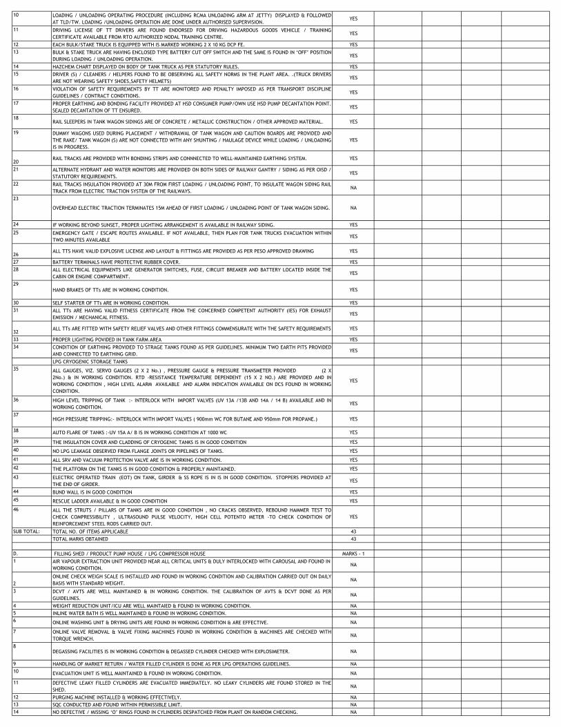
10 LOADING / UNLOADING OPERATING PROCEDURE (INCLUDING RCMA UNLOADING ARM AT JETTY) DISPLAYED & FOLLOWED
AT TLD/TW. LOADING /UNLOADING OPERATION ARE DONE UNDER AUTHORISED SUPERVISION.YES
11 DRIVING LICENSE OF TT DRIVERS ARE FOUND ENDORSED FOR DRIVING HAZARDOUS GOODS VEHICLE / TRAINING
CERTIFICATE AVAILABLE FROM RTO AUTHORIZED NODAL TRAINING CENTRE.YES
12 EACH BULK/STAKE TRUCK IS EQUIPPED WITH IS MARKED WORKING 2 X 10 KG DCP FE. YES
13 BULK & STAKE TRUCK ARE HAVING ENCLOSED TYPE BATTERY CUT OFF SWITCH AND THE SAME IS FOUND IN „OFF‟ POSITION
DURING LOADING / UNLOADING OPERATION.YES
14 HAZCHEM CHART DISPLAYED ON BODY OF TANK TRUCK AS PER STATUTORY RULES. YES
15 DRIVER (S) / CLEANERS / HELPERS FOUND TO BE OBSERVING ALL SAFETY NORMS IN THE PLANT AREA. .(TRUCK DRIVERS
ARE NOT WEARING SAFETY SHOES,SAFETY HELMETS) YES
16 VIOLATION OF SAFETY REQUIREMENTS BY TT ARE MONITORED AND PENALTY IMPOSED AS PER TRANSPORT DISCIPLINE
GUIDELINES / CONTRACT CONDITIONS.YES
17 PROPER EARTHING AND BONDING FACILITY PROVIDED AT HSD CONSUMER PUMP/OWN USE HSD PUMP DECANTATION POINT.
SEALED DECANTATION OF TT ENSURED.YES
18RAIL SLEEPERS IN TANK WAGON SIDINGS ARE OF CONCRETE / METALLIC CONSTRUCTION / OTHER APPROVED MATERIAL. YES
19 DUMMY WAGONS USED DURING PLACEMENT / WITHDRAWAL OF TANK WAGON AND CAUTION BOARDS ARE PROVIDED AND
THE RAKE/ TANK WAGON (S) ARE NOT CONNECTED WITH ANY SHUNTING / HAULAGE DEVICE WHILE LOADING / UNLOADING
IS IN PROGRESS.
YES
20RAIL TRACKS ARE PROVIDED WITH BONDING STRIPS AND CONNNECTED TO WELL-MAINTAINED EARTHING SYSTEM. YES
21 ALTERNATE HYDRANT AND WATER MONITORS ARE PROVIDED ON BOTH SIDES OF RAILWAY GANTRY / SIDING AS PER OISD /
STATUTORY REQUIREMENTS.YES
22 RAIL TRACKS INSULATION PROVIDED AT 30M FROM FIRST LOADING / UNLOADING POINT, TO INSULATE WAGON SIDING RAIL
TRACK FROM ELECTRIC TRACTION SYSTEM OF THE RAILWAYS.NA
23
OVERHEAD ELECTRIC TRACTION TERMINATES 15M AHEAD OF FIRST LOADING / UNLOADING POINT OF TANK WAGON SIDING. NA
24 IF WORKING BEYOND SUNSET, PROPER LIGHTING ARRANGEMENT IS AVAILABLE IN RAILWAY SIDING. YES
25 EMERGENCY GATE / ESCAPE ROUTES AVAILABLE. IF NOT AVAILABLE, THEN PLAN FOR TANK TRUCKS EVACUATION WITHIN
TWO MINUTES AVAILABLEYES
26ALL TTS HAVE VALID EXPLOSIVE LICENSE AND LAYOUT & FITTINGS ARE PROVIDED AS PER PESO APPROVED DRAWING YES
27 BATTERY TERMINALS HAVE PROTECTIVE RUBBER COVER. YES
28 ALL ELECTRICAL EQUIPMENTS LIKE GENERATOR SWITCHES, FUSE, CIRCUIT BREAKER AND BATTERY LOCATED INSIDE THE
CABIN OR ENGINE COMPARTMENT.YES
29HAND BRAKES OF TTs ARE IN WORKING CONDITION. YES
30 SELF STARTER OF TTs ARE IN WORKING CONDITION. YES
31 ALL TTs ARE HAVING VALID FITNESS CERTIFICATE FROM THE CONCERNED COMPETENT AUTHORITY (IES) FOR EXHAUST
EMISSION / MECHANICAL FITNESS.YES
32ALL TTs ARE FITTED WITH SAFETY RELIEF VALVES AND OTHER FITTINGS COMMENSURATE WITH THE SAFETY REQUIREMENTS YES
33 PROPER LIGHTING POVIDED IN TANK FARM AREA YES
34 CONDITION OF EARTHING PROVIDED TO STRAGE TANKS FOUND AS PER GUIDELINES. MINIMUM TWO EARTH PITS PROVIDED
AND CONNECTED TO EARTHING GRID.YES
LPG CRYOGENIC STORAGE TANKS
35 ALL GAUGES, VIZ. SERVO GAUGES (2 X 2 No.) , PRESSURE GAUGE & PRESSURE TRANSMETER PROVIDED (2 X
2No.) & IN WORKING CONDITION. RTD -RESISTANCE TEMPERATURE DEPENDENT (15 X 2 NO.) ARE PROVIDED AND IN
WORKING CONDITION , HIGH LEVEL ALARM AVAILABLE AND ALARM INDICATION AVAILABLE ON DCS FOUND IN WORKING
CONDITION.
YES
36 HIGH LEVEL TRIPPING OF TANK :- INTERLOCK WITH IMPORT VALVES (UV 13A /13B AND 14A / 14 B) AVAILABLE AND IN
WORKING CONDITION. YES
37HIGH PRESSURE TRIPPING:- INTERLOCK WITH IMPORT VALVES ( 900mm WC FOR BUTANE AND 950mm FOR PROPANE.) YES
38 AUTO FLARE OF TANKS :-UV 15A A/ B IS IN WORKING CONDITION AT 1000 WC YES
39 THE INSULATION COVER AND CLADDING OF CRYOGENIC TANKS IS IN GOOD CONDITION YES
40 NO LPG LEAKAGE OBSERVED FROM FLANGE JOINTS OR PIPELINES OF TANKS. YES
41 ALL SRV AND VACUUM PROTECTION VALVE ARE IS IN WORKING CONDITION. YES
42 THE PLATFORM ON THE TANKS IS IN GOOD CONDITION & PROPERLY MAINTAINED. YES
43 ELECTRIC OPERATED TRAIN (EOT) ON TANK, GIRDER & SS ROPE IS IN IS IN GOOD CONDITION. STOPPERS PROVIDED AT
THE END OF GIRDER. YES
44 BUND WALL IS IN GOOD CONDITION YES
45 RESCUE LADDER AVAILABLE & IN GOOD CONDITION YES
46 ALL THE STRUTS / PILLARS OF TANKS ARE IN GOOD CONDITION , NO CRACKS OBSERVED, REBOUND HAMMER TEST TO
CHECK COMPRESSIBILITY , ULTRASOUND PULSE VELOCITY, HIGH CELL POTENTO METER -TO CHECK CONDITION OF
REINFORCEMENT STEEL RODS CARRIED OUT.
YES
SUB TOTAL: TOTAL NO. OF ITEMS APPLICABLE 43
TOTAL MARKS OBTAINED 43
D. FILLING SHED / PRODUCT PUMP HOUSE / LPG COMPRESSOR HOUSE MARKS - 1
1 AIR VAPOUR EXTRACTION UNIT PROVIDED NEAR ALL CRITICAL UNITS & DULY INTERLOCKED WITH CAROUSAL AND FOUND IN
WORKING CONDITION.NA
2
ONLINE CHECK WEIGH SCALE IS INSTALLED AND FOUND IN WORKING CONDITION AND CALIBRATION CARRIED OUT ON DAILY
BASIS WITH STANDARD WEIGHT.NA
3 DCVT / AVTS ARE WELL MAINTAINED & IN WORKING CONDITION. THE CALIBRATION OF AVTS & DCVT DONE AS PER
GUIDELINES.NA
4 WEIGHT REDUCTION UNIT/ICU ARE WELL MAINTAIED & FOUND IN WORKING CONDITION. NA
5 INLINE WATER BATH IS WELL MAINTAINED & FOUND IN WORKING CONDITION. NA
6 ONLINE WASHING UNIT & DRYING UNITS ARE FOUND IN WORKING CONDITION & ARE EFFECTIVE. NA
7 ONLINE VALVE REMOVAL & VALVE FIXING MACHINES FOUND IN WORKING CONDITION & MACHINES ARE CHECKED WITH
TORQUE WRENCH.NA
8DEGASSING FACILITIES IS IN WORKING CONDITION & DEGASSED CYLINDER CHECKED WITH EXPLOSIMETER. NA
9 HANDLING OF MARKET RETURN / WATER FILLED CYLINDER IS DONE AS PER LPG OPERATIONS GUIDELINES. NA
10 EVACUATION UNIT IS WELL MAINTAINED & FOUND IN WORKING CONDITION. NA
11 DEFECTIVE LEAKY FILLED CYLINDERS ARE EVACUATED IMMEDIATELY. NO LEAKY CYLINDERS ARE FOUND STORED IN THE
SHED.NA
12 PURGING MACHINE INSTALLED & WORKING EFFECTIVELY. NA
13 SQC CONDUCTED AND FOUND WITHIN PERMISSIBLE LIMIT. NA
14 NO DEFECTIVE / MISSING „O‟ RINGS FOUND IN CYLINDERS DESPATCHED FROM PLANT ON RANDOM CHECKING. NA
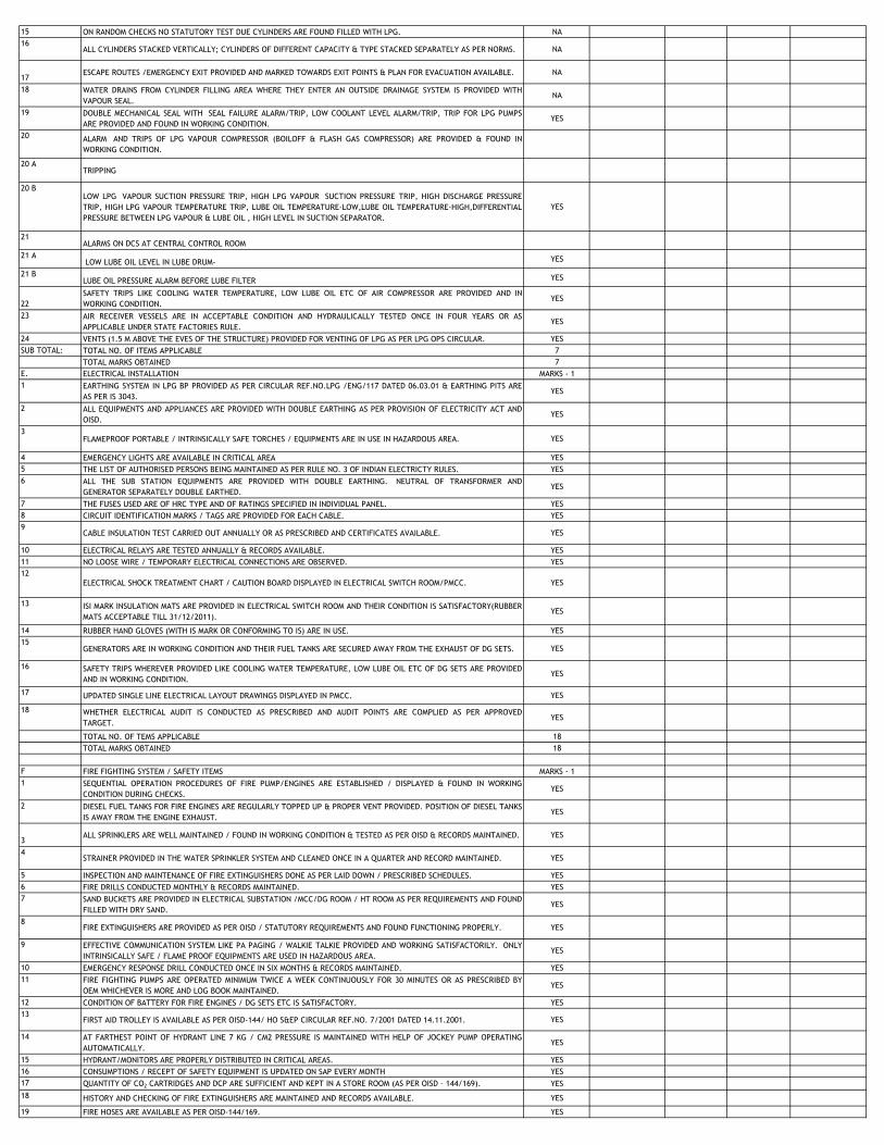
15 ON RANDOM CHECKS NO STATUTORY TEST DUE CYLINDERS ARE FOUND FILLED WITH LPG. NA
16ALL CYLINDERS STACKED VERTICALLY; CYLINDERS OF DIFFERENT CAPACITY & TYPE STACKED SEPARATELY AS PER NORMS. NA
17ESCAPE ROUTES /EMERGENCY EXIT PROVIDED AND MARKED TOWARDS EXIT POINTS & PLAN FOR EVACUATION AVAILABLE. NA
18 WATER DRAINS FROM CYLINDER FILLING AREA WHERE THEY ENTER AN OUTSIDE DRAINAGE SYSTEM IS PROVIDED WITH
VAPOUR SEAL.NA
19 DOUBLE MECHANICAL SEAL WITH SEAL FAILURE ALARM/TRIP, LOW COOLANT LEVEL ALARM/TRIP, TRIP FOR LPG PUMPS
ARE PROVIDED AND FOUND IN WORKING CONDITION.YES
20 ALARM AND TRIPS OF LPG VAPOUR COMPRESSOR (BOILOFF & FLASH GAS COMPRESSOR) ARE PROVIDED & FOUND IN
WORKING CONDITION.
20 ATRIPPING
20 BLOW LPG VAPOUR SUCTION PRESSURE TRIP, HIGH LPG VAPOUR SUCTION PRESSURE TRIP, HIGH DISCHARGE PRESSURE
TRIP, HIGH LPG VAPOUR TEMPERATURE TRIP, LUBE OIL TEMPERATURE-LOW,LUBE OIL TEMPERATURE-HIGH,DIFFERENTIAL
PRESSURE BETWEEN LPG VAPOUR & LUBE OIL , HIGH LEVEL IN SUCTION SEPARATOR.
YES
21ALARMS ON DCS AT CENTRAL CONTROL ROOM
21 A LOW LUBE OIL LEVEL IN LUBE DRUM- YES
21 BLUBE OIL PRESSURE ALARM BEFORE LUBE FILTER YES
22
SAFETY TRIPS LIKE COOLING WATER TEMPERATURE, LOW LUBE OIL ETC OF AIR COMPRESSOR ARE PROVIDED AND IN
WORKING CONDITION.YES
23 AIR RECEIVER VESSELS ARE IN ACCEPTABLE CONDITION AND HYDRAULICALLY TESTED ONCE IN FOUR YEARS OR AS
APPLICABLE UNDER STATE FACTORIES RULE.YES
24 VENTS (1.5 M ABOVE THE EVES OF THE STRUCTURE) PROVIDED FOR VENTING OF LPG AS PER LPG OPS CIRCULAR. YES
SUB TOTAL: TOTAL NO. OF ITEMS APPLICABLE 7
TOTAL MARKS OBTAINED 7
E. ELECTRICAL INSTALLATION MARKS - 1
1 EARTHING SYSTEM IN LPG BP PROVIDED AS PER CIRCULAR REF.NO.LPG /ENG/117 DATED 06.03.01 & EARTHING PITS ARE
AS PER IS 3043.YES
2 ALL EQUIPMENTS AND APPLIANCES ARE PROVIDED WITH DOUBLE EARTHING AS PER PROVISION OF ELECTRICITY ACT AND
OISD.YES
3FLAMEPROOF PORTABLE / INTRINSICALLY SAFE TORCHES / EQUIPMENTS ARE IN USE IN HAZARDOUS AREA. YES
4 EMERGENCY LIGHTS ARE AVAILABLE IN CRITICAL AREA YES
5 THE LIST OF AUTHORISED PERSONS BEING MAINTAINED AS PER RULE NO. 3 OF INDIAN ELECTRICTY RULES. YES
6 ALL THE SUB STATION EQUIPMENTS ARE PROVIDED WITH DOUBLE EARTHING. NEUTRAL OF TRANSFORMER AND
GENERATOR SEPARATELY DOUBLE EARTHED.YES
7 THE FUSES USED ARE OF HRC TYPE AND OF RATINGS SPECIFIED IN INDIVIDUAL PANEL. YES
8 CIRCUIT IDENTIFICATION MARKS / TAGS ARE PROVIDED FOR EACH CABLE. YES
9CABLE INSULATION TEST CARRIED OUT ANNUALLY OR AS PRESCRIBED AND CERTIFICATES AVAILABLE. YES
10 ELECTRICAL RELAYS ARE TESTED ANNUALLY & RECORDS AVAILABLE. YES
11 NO LOOSE WIRE / TEMPORARY ELECTRICAL CONNECTIONS ARE OBSERVED. YES
12
ELECTRICAL SHOCK TREATMENT CHART / CAUTION BOARD DISPLAYED IN ELECTRICAL SWITCH ROOM/PMCC. YES
13 ISI MARK INSULATION MATS ARE PROVIDED IN ELECTRICAL SWITCH ROOM AND THEIR CONDITION IS SATISFACTORY(RUBBER
MATS ACCEPTABLE TILL 31/12/2011).YES
14 RUBBER HAND GLOVES (WITH IS MARK OR CONFORMING TO IS) ARE IN USE. YES
15GENERATORS ARE IN WORKING CONDITION AND THEIR FUEL TANKS ARE SECURED AWAY FROM THE EXHAUST OF DG SETS. YES
16 SAFETY TRIPS WHEREVER PROVIDED LIKE COOLING WATER TEMPERATURE, LOW LUBE OIL ETC OF DG SETS ARE PROVIDED
AND IN WORKING CONDITION.YES
17 UPDATED SINGLE LINE ELECTRICAL LAYOUT DRAWINGS DISPLAYED IN PMCC. YES
18 WHETHER ELECTRICAL AUDIT IS CONDUCTED AS PRESCRIBED AND AUDIT POINTS ARE COMPLIED AS PER APPROVED
TARGET.YES
TOTAL NO. OF TEMS APPLICABLE 18
TOTAL MARKS OBTAINED 18
F FIRE FIGHTING SYSTEM / SAFETY ITEMS MARKS - 1
1 SEQUENTIAL OPERATION PROCEDURES OF FIRE PUMP/ENGINES ARE ESTABLISHED / DISPLAYED & FOUND IN WORKING
CONDITION DURING CHECKS.YES
2 DIESEL FUEL TANKS FOR FIRE ENGINES ARE REGULARLY TOPPED UP & PROPER VENT PROVIDED. POSITION OF DIESEL TANKS
IS AWAY FROM THE ENGINE EXHAUST.YES
3ALL SPRINKLERS ARE WELL MAINTAINED / FOUND IN WORKING CONDITION & TESTED AS PER OISD & RECORDS MAINTAINED. YES
4STRAINER PROVIDED IN THE WATER SPRINKLER SYSTEM AND CLEANED ONCE IN A QUARTER AND RECORD MAINTAINED. YES
5 INSPECTION AND MAINTENANCE OF FIRE EXTINGUISHERS DONE AS PER LAID DOWN / PRESCRIBED SCHEDULES. YES
6 FIRE DRILLS CONDUCTED MONTHLY & RECORDS MAINTAINED. YES
7 SAND BUCKETS ARE PROVIDED IN ELECTRICAL SUBSTATION /MCC/DG ROOM / HT ROOM AS PER REQUIREMENTS AND FOUND
FILLED WITH DRY SAND.YES
8FIRE EXTINGUISHERS ARE PROVIDED AS PER OISD / STATUTORY REQUIREMENTS AND FOUND FUNCTIONING PROPERLY. YES
9 EFFECTIVE COMMUNICATION SYSTEM LIKE PA PAGING / WALKIE TALKIE PROVIDED AND WORKING SATISFACTORILY. ONLY
INTRINSICALLY SAFE / FLAME PROOF EQUIPMENTS ARE USED IN HAZARDOUS AREA.YES
10 EMERGENCY RESPONSE DRILL CONDUCTED ONCE IN SIX MONTHS & RECORDS MAINTAINED. YES
11 FIRE FIGHTING PUMPS ARE OPERATED MINIMUM TWICE A WEEK CONTINUOUSLY FOR 30 MINUTES OR AS PRESCRIBED BY
OEM WHICHEVER IS MORE AND LOG BOOK MAINTAINED.YES
12 CONDITION OF BATTERY FOR FIRE ENGINES / DG SETS ETC IS SATISFACTORY. YES
13FIRST AID TROLLEY IS AVAILABLE AS PER OISD-144/ HO S&EP CIRCULAR REF.NO. 7/2001 DATED 14.11.2001. YES
14 AT FARTHEST POINT OF HYDRANT LINE 7 KG / CM2 PRESSURE IS MAINTAINED WITH HELP OF JOCKEY PUMP OPERATING
AUTOMATICALLY.YES
15 HYDRANT/MONITORS ARE PROPERLY DISTRIBUTED IN CRITICAL AREAS. YES
16 CONSUMPTIONS / RECEPT OF SAFETY EQUIPMENT IS UPDATED ON SAP EVERY MONTH YES
17 QUANTITY OF CO2 CARTRIDGES AND DCP ARE SUFFICIENT AND KEPT IN A STORE ROOM (AS PER OISD – 144/169). YES
18 HISTORY AND CHECKING OF FIRE EXTINGUISHERS ARE MAINTAINED AND RECORDS AVAILABLE. YES
19 FIRE HOSES ARE AVAILABLE AS PER OISD-144/169. YES
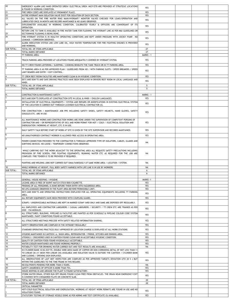
20 EMERGENCY ALARM LIKE HAND OPERATED SIREN/ ELECTRICAL SIREN /MCP/ETB ARE PROVIDED AT STRATEGIC LOCATIONS
& FOUND IN WORKING CONDITION.YES
21 FIRE SIREN CODES ARE DISPLAYED AT PROMINENT PLACE. YES
22 IN FIRE HYDRANT MAIN ISOLATION VALVE EXIST FOR ISOLATION OF EACH SECTION. YES
23 ALL VALVES ON THE FIRE WATER RING MAIN/HYDRANT/ MONITOR VALVES CHECKED FOR LEAKS/OPERATION AND
LUBRICATED ONCE IN MONTH AND RECORD MAINTAINED & NO LEAKS OBSERVED.YES
24 EXPLOSIMETER AVAILABLE IN WORKING CONDITION, CALIBRATED YEARLY & OFFICERS ARE CONVERSANT OF ITS
OPERATION.YES
25
RETURN LINE TO TANK IS AVAILABLE IN FIRE WATER TANK FOR FLUSHING THE HYDRANT LINE AS PER M&I GUIDELINES OR
SECTIONWISE FLUSHING IS BEING DONE.YES
26 FIRE HYDRANT SYSTEM IS IN HEALTHY OPERATING CONDITIONS AND KEPT UNDER PRESSURE WITH JOCKEY PUMP. NO
LEAKAGE / CORROSION OBSERVED.YES
27 ALARM INDICATION SYSTEM LIKE LOW LUBE OIL, HIGH WATER TEMPERATURE FOR FIRE FIGHTING ENGINES IS PROVIDED
AND WORKING.YES
SUB TOTAL: TOTAL NO. OF ITEMS APPLICABLE 27
TOTAL MARKS OBTAINED 27
G TT PARKING AREA: MARKS - 1
1TRUCK PARKING AREA PROVIDED AT LOCATIONS FOUND ADEQUATELY COVERED BY HYDRANT SYSTEM. YES
2 NO TT CREW FOUND LOITERING / SLEEPING / COOKING BENEATH THE TANK TRUCK OR IN TT PARKING AREA. YES
3TT PARKING AREA IS AS PER APPROVED PLAN / GUIDELINES FROM HO / WITH PARKING SLOTS / SPEED BREAKERS / SPEED
LIMIT BOARDS AND ENTRY / EXIT CONTROL.YES
4 TT CREW REST ROOM FACILITIES ARE MAINTAINED CLEAN & IN HYGIENIC CONDITION. YES
5 DO‟S AND DON‟TS AND SAFE DRIVING PRACTICES HAVE BEEN DISPLAYED IN DRIVERS REST ROOM IN LOCAL LANGUAGE AND
HINDI.YES
SUB TOTAL: TOTAL NO. OF ITEMS APPLICABLE 5
TOTAL MARKS OBTAINED 5
H. CONSTRUCTION & MAINTENANCE SAFETY MARKS - 1
1 DO‟S AND DON‟TS DISPLAYED AT CONSTRUCTION SITE IN LOCAL & HINDI / ENGLISH LANGUAGES. YES
2 INSTALLATION OF ELECTRICAL EQUIPMENTS / SYSTEM AND REPAIRS OR MODIFICATIONS IN EXISTING ELECTRICAL SYSTEM
OF THE LOCATION IS CARRIED OUT THROUGH LICENSED ELECTRICAL CONTRACTOR (S).YES
3
FOR CONSTRUCTION / MAINTENANCE JOB PPE INCLUDING SAFETY SHOES, SAFETY HELMETS, HAND GLOVES, SAFETY
GOGGLES ETC. ARE IN USEYES
4 ALL MAINTENANCE WORKS AND CONSTRUCTION WORKS ARE DONE UNDER THE SUPERVISION OF COMPETENT PERSONS OF
CONTRACTOR AND / OR REPRESENTATIVE OF IOCL AND WORK PERMIT FOR HOT / COLD / /ELECTRICAL ISOLATION AND
ENERGISATION /WORKING AT HEIGHT, ETC IS IN USE.
YES
5DAILY SAFETY TALK BEFORE START OF WORK AT SITE IS GIVEN BY THE SITE SUPERVISOR AND RECORDS MAINTAINED. YES
6 NO UNAUTHORISED CONTRACT WORKER IS ALLOWED FREE ACCESS IN OPERATING AREA. YES
7POWER CONNECTION PROVIDED TO THE CONTRACTOR IS THROUGH APPROVED TYPE OF ISOLATORS, CABLES, GLANDS AND
EARTHING DEVICES. NO LOOSE / TEMPORARY CONNECTIONS OBSERVED.NA
8WHILE CARRYING OUT THE WORK ADJACENT TO THE OPERATING AREA ALL REQUISTE SAFETY PRECAUTIONS INCLUDING
PROVISION OF FIRE SCREEN, FIRE FIGHTING EQUIPMENTS, RUNNING WATER ETC AS REQUIRED FOR THE JOB ARE
COMPLIED. FIRE TENDER IS TO BE PROVIDED IF REQUIRED.
NA
9PAINTING AND WELDING JOBS NOT CARRIED OUT SIMULTANEOUSLY AT SAME WORK AREA / LOCATION / SYSTEM. NA
10 WHILE WORKING AT HEIGHT, FULL BODY SAFETY HARNESS WITH LIFE LINE IS IN USE BY WORKERS NA
SUB TOTAL: TOTAL NO. OF ITEMS APPLICABLE 6
TOTAL MARKS OBTAINED 6
I GENERAL/ HOUSE KEEPING / HYGIENE MARKS -1
1 LICENSE AREA IS FREE OF BURNT MATCH STICK/BIDI/CIGARETTE. YES
2 FRISKING OF ALL PERSONNEL IS DONE BEFORE THEIR ENTRY INTO HAZARDOUS AREA. YES
3 NO LPG LEAKAGES OBSERVED IN THE PLANT AREA BEYOND PERMISSIBLE LIMIT. YES
4 DO‟S AND DON‟TS AND OPERATING INSTRUCTIONS DISPLAYED FOR ALL OPERATING EQUIPMENTS INCLUDING TT PARKING
AREA.YES
5 ALL ROTARY EQUIPMENTS HAVE BEEN PROVIDED WITH COUPLING GUARD. YES
6SCRAPS / UNSERVICEABLE MATERIALS ARE KEPT IN MARKED SCRAP YARD ONLY AND SAME ARE DISPOSED OFF REGULARLY. YES
7 ALL EMPLOYEES AND CONTRACTOR LABOURERS / CASUAL LABOURERS / SECURITY / TT CREW ETC ARE TRAINED AS PER
OISD – 154 MODULES.YES
8 ALL STRUCTURES, BUILDING, PIPELINES & FACILITIES ARE PAINTED AS PER SCHEDULE & PIPELINE COLOUR CODE SYSTEM
MAINTAINED. PAINT CONDITIONS FOUND ACCEPTABLE.YES
9ALL STRUCTURED MEETINGS PRECEDE WITH SAFETY RELATED INFORMATION SHARING. YES
10 SAFETY OBSERVATIONS ARE COMPLIED IN THE INTRANET REGULARLY YES
11STANDARD OPERATING PRACTICES DULY APPROVED BY LOCATION CHARGE IS DISPLAYED AT ALL WORK STATIONS YES
12 HYGIENE MAINTAINED IN CANTEEN i.e. WASH AREA, REFRIGERATOR / FRIDGE, KITCHEN AND DINNING AREA. YES
13 UTENSILS / CROCKERIES USED IN CANTEEN FOUND CLEAN AND IN ACCEPTABLE HYGIENIC CONDITION. YES
14 QUALITY OF CANTEEN FOOD FOUND HYGIENICALLY ACCEPTABLE. YES
15 WATER COOLER MAINTAINED AND FOUND WORKING PROPERLY. YES
16 POTABILITY TEST FOR DRINKING WATER CARRIED OUT AND TEST RESULTS ARE AVAILABLE. NA
17 IN CYLINDER BANK 10 KG DCP FE, DOUBLE WIRE MESH MADE OF COPPER OR NON CORRODING METAL OF NOT LESS THAN 11
TO LINEAR CM (11 MESH PER LINEAR CM) AVAILABLE AND ISOLATION VALVE IS OUTSIDE THE CANTEEN / CYLINDER BANK
AND CLOSING / OPENING SIGN DISPLAYED.
YES
18 ALL OBSERVATIONS OF LAST MDT INSPECTION ARE COMPLIED AS PER APPROVED TARGET( DEVIATION UTO 20 % ) BUT
WITHIN THE GUIDELINES TO THE TIME FRAME IN THIS REGARD.YES
19 NO ESA POINTS PENDING FOR MORE THAN 2 YEARS. NA
20 SAFETY AWARENESS OF OFFICER IS MORE THAN 75%. YES
21 HOUSE KEEPING IN AND AROUND THE PLANT IS FOUND SATISFACTORY. YES
22
STORM WATER DRAIN, OTHER RUN OFF DRAINS FOUND CLEAN FREE FROM OBSTACLES. THE DRAIN NEAR EMERGENCY EXIT
IS COVERED WITH CHEQUERED PLATE OR CONCRETE SLAB.YES
SUB TOTAL: TOTAL NO. OF ITEMS APPLICABLE 20
TOTAL MARKS OBTAINED 20
J CRITICAL PARAMETER
1
HOT/COLD/ELECTRICAL ISOLATION AND ENERGISATION, WORKING AT HEIGHT WORK PERMITS ARE FOUND IN USE AND NO
VIOLATIONS FOUND.YES
2 STATUTORY TESTING OF STORAGE VESSELS DONE AS PER NORMS AND TEST CERTIFICATE (S) AVAILABLE. YES

3 HYDRO TEST OF FIRE EXTINGUISHER DONE ONCE IN THREE YEARS OR AS PRESCRIBED / STATUTORILY REQUIRED AND
RECORDS AVAILABLE.YES
4 SAFETY CHECKS OF TANK TRUCKS ARE CARRIED OUT REGULARLY & RECORDS MAINTAINED. YES
5 ALL GAUGES, VIZ. TWO INDEPENDENT LEVEL GAUGE INDICATORS, PRESSURE & TEMP. GAUGES, HIGH LEVEL ALARM SWITCH
ETC ARE PROVIDED ON STORAGE VESSEL AND FOUND IN WORKING CONDITION.YES
6 HIGH LEVEL ALARMS PROVIDED IN STORAGE VESSELS INTERLOCKED WITH ROVs. (CHECK FOR AUDIO VISUAL ALARM AT
CENTRAL CONTROL ROOM).YES
7 REMOTE OPERATED VALVE (ROVs) ARE IN WORKING CONDITION AND OPERABLE BOTH FROM LOCAL AS WELL AS REMOTE
POSITION.YES
8 VAPOUR TRAP EXISTS IN THE SUMP OF EACH VESSEL APRON BEFORE DISCHARGING IN THE STORM WATER DRAIN AS PER
OISD 144 AND WATER SEAL MAINTAINED PROPERLY.YES
9INTERLOCK SHUT DOWN SYSTEM AS PER OISD-144 CLAUSE NO.11.11 (iv) IS AVAILABLE AND IN WORKING CONDITION. NO
10 BONDING / EARTHING OF BULK TRUCKS DONE PROPERLY. ALL METALLIC STRUCTURES ARE PROPERLY EARTHED. YES
11 BULK & STAKE TRUCKS ENTERING PLANT OPERATIONAL AREA HAVE CCOE APPROVED SPARK ARRESTOR. YES
12 NO FLAMMABLE / PROHIBITED SUBSTANCES LIKE BIDDI /CIGARETTE, PETROL/ DIESEL CAN, MATCH BOX ETC ARE FOUND IN
BULK/STAKE TRUCK CABIN.YES
13 NO LOOSE / TEMPORARY WIRING FOUND IN TT. YES
14 LPG CYLINDERS WITH SAFETY CAP IF INTRODUCED IN CAROUSAL / FILLING M/C, LPG FILLING OPERATION DOES NOT START
OR NO LEAKAGE OBSERVED FROM FILLING GUN.NA
15EVACUATION VESSELS (BOIL OFF RECEIVERS, ETHYL MERCAPTEN DRUM ) BELOW 1 MT ARE HYDRAULICALLY TESTED ONCE
IN FOUR YEARS OR AS APPLICABLE UNDER STATE FACTORIES RULE & EQUIPPED WITH WORKING PRESSURE GAUGE, LEVEL
GAUGE, HIGH LEVEL ALARM, PRESSURE SRVS, ETC & PROVIDED WITH SWITCH OVER ARRANGEMENT
NA
16 MASTIC FLOORING IN CYLINDER SHED HAS BEEN PROVIDED & MAINTAINED. NA
17 LPG HOSES FOR CAROUSAL FILLING GUN/EVACUATION GUN/ICU ARE TESTED ONCE IN FOUR MONTHS AS PER OISD-135 AND
RECORDS MAINTAINED.NA
18 CABLE ENTRY AT JUNCTION BOX IN HAZARDOUS AREA IS THROUGH DOUBLE COMPRESSION GLANDS (PROPER EMBOSSING
OF CMRI/CMRI NO. AVAILABLE FOR FLAME PROOF ). GLANDS ARE PROPERLY TIGHTENED AND CABLES IN THE GLANDS ARE
NOT LOOSE.
YES
19 EARTHING RESISTANCE FOR INDIVIDUAL EARTH PITS IN ISOLATED CONDITION, FOR GRID AND CONTACT RESISTANCE POINTS
IS WITHIN PRESCRIBED LIMITS AND RECORDS PROPERLY MAINTAINED.YES
20 LIGHTNING PROTECTION ARE PROVIDED IN ALL PRODUCT PUMP HOUSE / TLF / TW GANTRY / LPG COMPRESSOR HOUSE
AS PER CIRCULAR REF.NO.LPG /ENG/117 DATED 06.03.01.YES
21FLAME PROOF EQUIPMENT ARE PROPERLY TIGHTENED WITH STANDARD FASTENERS AND NO FASTENER IS MISSING YES
22 HYDRANT SYSTEM / SPRINKLER SYSTEM IS ON AUTO. YES
23 WATER TANKS FOR FIRE FIGHITNG ARE KEPT FULL ( MINIMUM UPTO OISD NORMS) CLEANED AS PER SCHEDULE AND LEVEL
GAUGES ARE IN WORKING CONDITIONYES
24 FIRE ENGINES AVAILABLE AS PER OISD-144. (AS PER OISD 5 NOS X 410 M3/HR. AVAILABLE 3 NOS X 410 M3/ H R AND 2
NO X 410 M3/HR AS STAND BY)YES
25 WATER STORAGE IS AVAILABLE AS PER OISD-144/169. ( AS PER OISD NORMS 4980 KL. AVAILABLE 7400KL) YES
26 GAS MONITORING SYSTEM & SENSORS ARE PROVIDED AS PER OISD 144 / WORKING / CALIBRATION DONE & RECORDS
MAINTAINED.YES
27PERSONAL PROTECTIVE EQUIPMENT SUCH AS HAND GLOVES / SAFETY SHOES / SAFETY HELMETS ETC ARE IN USE. YES
28 ALL DELUGE VALVES ARE WELL MAINTAINED/ FOUND IN WORKING CONDITION & TESTED ONCE IN A QUARTER & RECORDS
MAINTAINED.YES
29 HYDRANT / MONITORS / DELUGE VALVE ARE EASILY ACCESSIBLE AND OPERABLE YES
SUB TOTAL: TOTAL NO. OF ITEMS APPLICABLE 25
TOTAL MARKS OBTAINED 24
K BOILER
VALID LICENSES AS PER IBR AVAILABLE / APPLIED FOR RENEWAL IN TIME. YES
1 TRIPPINGS
a SCANNER COOLING FAN YES
b FD FAN YES
c FLAME SCANNER YES
d 3 ELEMENT BOILER DRUM LEVEL CONTROL YES
2NO LPG LEAKAGES OBSERVED IN DIESEL & HSD PIPELINETHE PLANT AREA BEYOND PERMISSIBLE LIMIT. YES
3NO LPG LEAKAGES OBSERVED IN ACID & ALKALI PIPELINETHE PLANT AREA BEYOND PERMISSIBLE LIMIT. YES
4 WATER TREATMENT PLANT IS IN WORKING CONDITION. YES
5 NDT OF ACID AND ALKALI STORAGE TANKS & PIPELINES CARRIED OUT YES
6 NO FLUE GAS LEAKAGE OBSERVED FROM THE CHIMNEY. YES
SUB TOTAL: TOTAL NO. OF ITEMS APPLICABLE 10
TOTAL MARKS OBTAINED 10
L HOT FLARE STACK
1 Hot Flare stack is in working condition. The temperature indication available in DCS at Central control room. YES
SUB TOTAL: TOTAL NO. OF ITEMS APPLICABLE 1
TOTAL MARKS OBTAINED 1
M WINCH SYSTEM OF RAIL WAY LOADING FACILITY
1 THE WINCH SYSTEM IS IN WORKING CONDITION AND TRIPPING SYSTEM WORKING TO AVOID DE-RAIL OF WAGON. YES
SUB TOTAL: TOTAL NO. OF ITEMS APPLICABLE 1
TOTAL MARKS OBTAINED 1
N HT DG SET
1 LOW LUBE OIL / LOW AIR PRESSURE / HIGH WATER TEMPERATURE / OVER SPEED AND EMERGENCY SHUT DOWN ARE
PROVIDED AND FOUND IN WORKING CONDITION..YES
SUB TOTAL: TOTAL NO. OF ITEMS APPLICABLE 1
TOTAL MARKS OBTAINED 1
N APARATUS FILLED STRUCTURE
1VAPOUR ANALYSER IN WORKING CONDITIONS AND REGULAR DATA MAINTAINED. YES
2
SUB TOTAL: TOTAL NO. OF ITEMS APPLICABLE 1
TOTAL MARKS OBTAINED 1
N MERCAPTAN DOSING PLANT
1GAS MASK, PPE'S AVAILABLE FOR PERSONNEL WORKING IN THE MERCAPTAN DOSING PLANT YES
2STANDARD OPERATING PRACTICES DULY APPROVED BY LOCATION CHARGE IS DISPLAYED
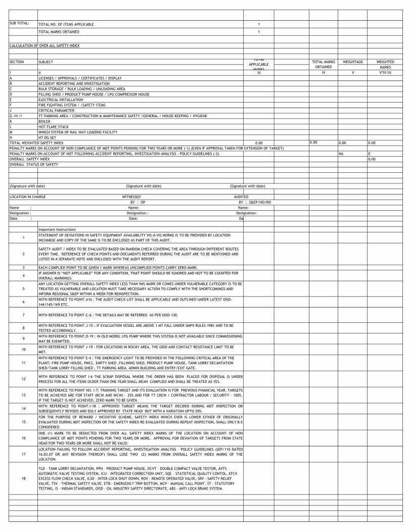
SUB TOTAL: TOTAL NO. OF ITEMS APPLICABLE 1
TOTAL MARKS OBTAINED 1
CALCULATION OF OVER ALL SAFETY INDEX
SECTION SUBJECT WEIGHTAGE WEIGHTED
MARKS
I II III IV V V*IV/III
A LICENSES / APPROVALS / CERTIFICATES / DISPLAY
B ACCIDENT REPORTING AND INVESTIGATION
C BULK STORAGE / BULK LOADING / UNLOADING AREA
D FILLING SHED / PRODUCT PUMP HOUSE / LPG COMPRESSOR HOUSE
E ELECTRICAL INSTALLATION
F FIRE FIGHTING SYSTEM / /SAFETY ITEMS
J CRITICAL PARAMETER
G /H /I TT PARKING AREA / CONSTRUCTION & MAINTENANCE SAFETY /GENERAL / HOUSE KEEPING / HYGIENE
K BOILER
L HOT FLARE STACK
M WINCH SYSTEM OF RAIL WAY LOADING FACILITY
N HT DG SET
TOTAL WEIGHTED SAFETY INDEX 0.00 0.00 0.00 0.00
PENALTY MARKS ON ACCOUNT OF NON COMPLIANCE OF MDT POINTS PENDING FOR TWO YEARS OR MORE (-1) (EVEN IF APPROVAL TAKEN FOR EXTENSION OF TARGET)
PENALTY MARKS ON ACCOUNT OF NOT FOLLOWING ACCIDENT REPORTING, INVESTIGATION ANALYSIS – POLICY GUIDELINES (-2) NA 0
OVERALL SAFETY INDEX 0.00
OVERALL STATUS OF SAFETY
(Signature with date) (Signature with date) (Signature with date)
LOCATION IN CHARGE WITNESSED AUDITED
BY : OP BY : S&EP/HO/RO
Name : Name: Name:
Designation : Designation : Designation:
Date : Date: Date: Date:
Important Instructions
1STATEMENT OF DEVIATIONS IN SAFETY EQUIPMENT AVAILABILITY VIS-À-VIS NORMS IS TO BE PROVIDED BY LOCATION-
INCHARGE AND COPY OF THE SAME IS TO BE ENCLOSED AS PART OF THIS AUDIT.
2
SAFETY AUDIT / INDEX TO BE EVALUATED BASED ON RANDOM CHECK COVERING THE AREA THROUGH DIFFERENT ROUTES
EVERY TIME. REFERENCE OF CHECK POINTS AND DOCUMENTS REFERRED DURING THE AUDIT ARE TO BE MENTIONED AND
LISTED IN A SEPARATE NOTE AND ENCLOSED WITH THE AUDIT REPORT.
3 EACH COMPLIED POINT TO BE GIVEN 1 MARK WHEREAS UNCOMPLIED POINTS CARRY ZERO MARK.
4IF ANSWER IS “NOT APPLICABLE” FOR ANY CONDITION, THAT POINT SHOULD BE IGNORED AND NOT TO BE COUNTED FOR
OVERALL MARKINGS.
5
ANY LOCATION GETTING OVERALL SAFETY INDEX LESS THAN 94% MARK OR COMES UNDER VULNERABLE CATEGORY IS TO BE
TREATED AS VULNERABLE AND LOCATION MUST TAKE NECESSARY ACTION TO COMPLY WITH THE SHORTCOMINGS AND
INFORM REGIONAL S&EP WITHIN A WEEK FOR REINSPECTION.
6WITH REFERENCE TO POINT.A16 : THE AUDIT CHECK LIST SHALL BE APPLICABLE AND OUTLINED UNDER LATEST OISD-
144/145/169 ETC.
7 WITH REFERENCE TO POINT.C-6 : THE DETAILS MAY BE REFERRED AS PER OISD-130.
8WITH REFERENCE TO POINT.J-15 : IF EVACUATION VESSEL ARE ABOVE 1 MT FALL UNDER SMPV RULES 1981 AND TO BE
TESTED ACCORDINGLY.
9WITH REFERENCE TO POINT.D-19 : IN OLD MODEL LPG PUMP WHERE THIS SYSTEM IS NOT AVAILABLE SINCE COMMISSIONING
MAY BE EXEMPTED.
10WITH REFERENCE TO POINT J-19 : FOR LOCATIONS IN ROCKY AREA, THE GRID AND CONTACT RESISTANCE LIMIT TO BE
MET.
11
WITH REFERENCE TO POINT E-4 : THE EMERGENCY LIGHT TO BE PROVIDED IN THE FOLLOWING CRITICAL AREA OF THE
PLANT; FIRE PUMP HOUSE, PMCC, EMPTY SHED ,FILLINING SHED, PRODUCT PUMP HOUSE, TANK LORRY DECANTATION
SHED/TANK LORRY FILLING SHED , TT PARKING AREA, ADMIN BUILDING AND ENTRY/EXIT GATE.
12WITH REFERENCE TO POINT I-6 THE SCRAP DISPOSAL WHERE THE ORDER HAS BEEN PLACED FOR DISPOSAL IS UNDER
PROCESS FOR ALL THE ITEMS OLDER THAN ONE YEAR SHALL MEAN COMPLIED AND SHALL BE TREATED AS YES.
13
WITH REFERENCE TO POINT NO. I-7: TRAINING TARGET AND ITS EVALUATION IS FOR PREVIOUS FINANCIAL YEAR. TARGETS
TO BE ACHIEVED ARE FOR STAFF (BCW AND WCW) – 35% AND FOR TT CREW / CONTRACTOR LABOUR / SECURITY – 100%.
IF THE TARGET IS NOT ACHIEVED, ZERO MARK TO BE GIVEN.
14WITH REFERENCE TO POINT.I-18 : APPROVED TARGET MEANS THE TARGET DECIDED DURING MDT INSPECTION OR
SUBSEQUENTLY REVISED AND DULY APPROVED BY STATE HEAD BUT WITH A VARIATION UPTO 20%.
15
FOR THE PURPOSE OF REWARD / INCENTIVE SCHEME, SAFETY INDEX WHICH EVER IS LOWER EITHER OF ORIGINALLY
EVALUATED DURING MDT INSPECTION OR THE SAFETY INDEX RE-EVALUATED DURING REPEAT INSPECTION, SHALL ONLY B E
CONSIDERED.
16
ONE (1) MARK TO BE DEDUCTED FROM OVER ALL SAFETY INDEX MARKS OF THE LOCATION ON ACCOUNT OF NON
COMPLIANCE OF MDT POINTS PENDING FOR TWO YEARS OR MORE. APPROVAL FOR DEVIATION OF TARGETS FROM STATE
HEAD FOR TWO YEARS OR MORE SHALL NOT BE VALID.
17
LOCATION FAILING TO FOLLOW ACCIDENT REPORTING, INVESTIGATION ANALYSIS – POLICY GUIDELINES (SEP/110 DATED
16.03.07 OR ANY REVISION THEREOF) SHALL LOSE TWO (2) MARKS FROM OVERALL SAFETY INDEX MARKS OF THE
LOCATION.
18
TLD – TANK LORRY DECANTATION, PPH – PRODUCT PUMP HOUSE, DCVT – DOUBLE COMPACT VALVE TESTOR, AVTS –
AUTOMATIC VALVE TESTING SYSTEM, ICU – INTEGRATED CORRECTION UNIT, SQC – STATISTICAL QUALITY CONTOL, EFCV –
EXCESS FLOW CHECK VALVE, ILSD – INTER LOCK SHUT DOWN, ROV – REMOTE OPERATED VALVE, SRV – SAFETY RELIEF
VALVE, TSV – THERMAL SAFETY VALVE, ETB – EMERGENCY TRIP BUTTON, MCP – MANUAL CALL POINT, ST – STATUTORY
TESTING, IS – INDIAN STANDARDS, OISD – OIL INDUSTRY SAFETY DIRECTORATE, ABS – ANTI LOCK BRAKE SYSTEM.
TOTAL
APPLICABLE
MARKS
TOTAL MARKS
OBTAINED
(Signature with date)
LOCATION IN CHARGE
Name : Name: Name:
Designation : Designation : Designation: