Embed Size (px)
Citation preview
OISD – STANDARD – 183
June , 1999
STANDARD ON LOGGING OPERATIONS
Prepared by : Committee on “Standard on Logging Operations”
OIL INDUSTRY SAFETY DIRECTORATE 2
nd Floor, “Kailash”
26, Kasturba Gandhi Marg, NEW DELHI – 110 001

2
FOREWORD The Oil Industry in India is more than 100 years old. Because of various collaboration agreements, a variety of international codes, standards and practices have been in vogue. Standardisation in design philosophies and operation and maintenance practices at a national level was hardly in existence. This coupled with feed back from some serious accidents that occurred in the recent past in India and abroad, emphasised the need for the industry to review the existing state- of- the-art in designing, operating and maintaining oil and gas installations. With this in view, the Ministry of Petroleum and Natural Gas in 1986 constituted a Safety Council assisted by the Oil Industry Safety Directorate (OISD) staffed from within the industry in formulating and implementing a series of self regulatory measures aimed at removing obsolescence, standardising and upgrading the existing standards to ensure safe operations. Accordingly, OISD constituted a number of functional committees of experts nominated from the industry to draw up standards and guidelines on various subjects. The present standard on “Logging Operations” was prepared by the Functional Committee on “Standard on Logging Operations”. The document is based on the accumulated knowledge and experience of industry members and the various national and international codes and practices. This standard is meant to be used as supplement and not as a replacement for existing codes and practices. It is hoped that provisions of this standard, if implemented objectively, may go a long way to improve the safety and reduce accidents in Oil and Gas Industry. Users are cautioned that no standard can be substitute for the judgement of a responsible and experienced geoscientist. Suggestions are invited from the users after it is put into practice to improve the document further. Suggestions for amendments to this document should be addressed to the Coordinator, Committee on “Logging Operations”, Oil Industry Safety Directorate, 2
nd Floor, Kailash, 26-
Kasturba Gandhi Marg, New Delhi – 110 001. This standard in no way supercedes the statutory requirements of bodies like DGMS, CCE or any other Government Body which must be followed as applicable.
3
NOTE
OISD (Oil Industry Safety Directorate) publications are prepared for use in the Oil and Gas
Industry under Ministry of Petroleum & Natural Gas. These are the property of Ministry of
Petroleum & Natural Gas and shall not be reproduced or copied and loaned or exhibited to others
without written consent from OISD.
Though every effort has been made to assure the accuracy and reliability of the data
contained in these documents, OISD hereby expressly disclaims any liability or responsibility for
loss or damage resulting from their use.
These documents are intended to supplement rather than replace the prevailing statutory
requirements.
4
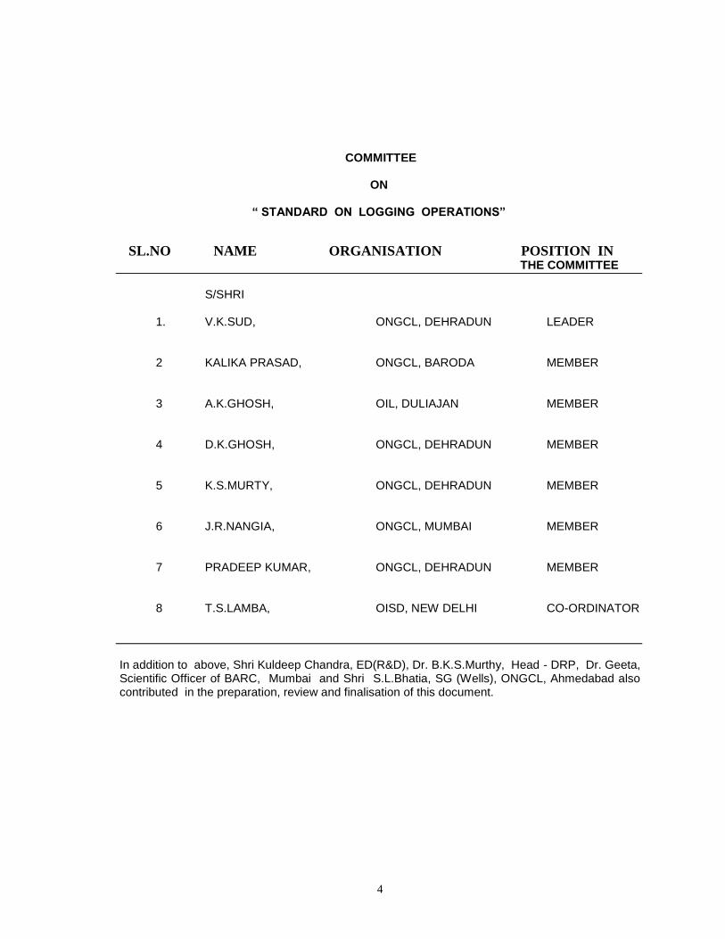
COMMITTEE
ON
“ STANDARD ON LOGGING OPERATIONS”
SL.NO NAME ORGANISATION POSITION IN THE COMMITTEE
S/SHRI
1. V.K.SUD, ONGCL, DEHRADUN LEADER
2 KALIKA PRASAD, ONGCL, BARODA MEMBER
3 A.K.GHOSH, OIL, DULIAJAN MEMBER
4 D.K.GHOSH, ONGCL, DEHRADUN MEMBER
5 K.S.MURTY, ONGCL, DEHRADUN MEMBER
6 J.R.NANGIA, ONGCL, MUMBAI MEMBER
7 PRADEEP KUMAR, ONGCL, DEHRADUN MEMBER
8 T.S.LAMBA, OISD, NEW DELHI CO-ORDINATOR
In addition to above, Shri Kuldeep Chandra, ED(R&D), Dr. B.K.S.Murthy, Head - DRP, Dr. Geeta, Scientific Officer of BARC, Mumbai and Shri S.L.Bhatia, SG (Wells), ONGCL, Ahmedabad also contributed in the preparation, review and finalisation of this document.
5
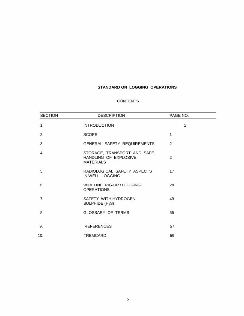
STANDARD ON LOGGING OPERATIONS
CONTENTS
SECTION DESCRIPTION PAGE NO.
1. INTRODUCTION 1 2. SCOPE 1 3. GENERAL SAFETY REQUIREMENTS 2 4. STORAGE, TRANSPORT AND SAFE
HANDLING OF EXPLOSIVE 2 MATERIALS
5. RADIOLOGICAL SAFETY ASPECTS 17 IN WELL LOGGING
6. WIRELINE RIG-UP / LOGGING 28 OPERATIONS
7. SAFETY WITH HYDROGEN 49 SULPHIDE (H2S)
8. GLOSSARY OF TERMS 55
9. REFERENCES 57
10. TREMCARD 59
6
1.0 INTRODUCTION:
Wireline Well Logging operations involve handling of surface equipment, heavy down hole tools, various kinds of explosives and radioactive sources at the bases or at the drill sites (both off-shore and on-shore) on regular basis.
Physical activities involving the use of machinery, tools, electrical and mechanical equipment, radioactive & explosive material are potentially hazardous and highly risk prone. Safety is of utmost importance in handling the above materials.
All the explosive materials and radioactive sources are dangerous and must be handled with great care. All the users must know and follow all approved safety procedures. World over logging companies have formulated safety rules to ensure the safety of their personnel during logging operations including handling of hazardous goods without violating the statutory regulations.
In India, use of explosives in oil industry is governed by the Chief Controller of Explosives, Nagpur and use of radioactive sources by BARC, Mumbai and overall operational activity by Director General, Mines Safety, Dhanbad. Keeping this in view, safety standard on ‘Logging Operations’ has been formulated. 2.0.0 SCOPE:
This standard recommends the safe practices and procedures to be followed during logging operations as well as handling of explosives and radioactive materials both ON-SHORE and OFF-SHORE. The scope of these practices lies in the following activities;
1. Wireline well logging operations
2. Perforation both wireline and tubing conveyed
3. Wireline Bridge plug/packer /cement retainer setting
4. Puncture/cutting/severing of casing, drill pipes & collars, tubing etc.
5. Cased hole formation testing
6. Side wall coring 7. Free point Indicator / String
shot 8. Storage, transportation &
safe handling of explosives 9. Radioactive logging
operations like density, neutron etc.
10. Storage, transportation & safe handling of radioactive materials.
11. Disposal / liquidation of non-usable explosives and radioactive materials.
The sole purpose of this standard is
to prevent accidents resulting in the loss to human life, property and environment. All the safety aspects documented are already in practice based upon continuous field experience and/or is a statutory requirement during the execution of all logging operations. Although, all efforts are made to make the present standard comprehensive in all respects , this shall require updation in future to keep pace with fast changing technological advancements.
3.0.0 GENERAL SAFETY
REQUIREMENT : The quality of equipment, timely inspection and appropriate repair /maintenance play a major role in safety management. However, the human factor plays the most vital role as most of the accidents are caused due to human failure. Keys to safety are ;
1. Safe and healthy working conditions.
2. Safe and proper equipment.
7
3. Safe transportation of equipment / personnel to the well-site.
4. Safe operating procedures. 5. Proper training. 6. Compliance with safety
regulations. 7. Company-wide
commitment to safety. 8. Periodic safety audits.
4.0.0 STORAGE, TRANSPORTATION &
SL.NO SAFE HANDLING OF EXPLOSIVE MATERIALS:
4.1.0 GENERAL:
1. Accident prevention results from careful planning and observance of the best practices.
2. Know and obey all local, national and international regulations and warnings about the explosives in use.
3. NEVER let any unauthorized person/ employee handle explosives.
4.2.0 GUN LOADING AT SHOP:
1. Shop must have a fixed gun loading area and limited storage of associated explosives with suitable security arrangement.
2. Manager Logging Services (Base) must make sure that the loading area meets all local, state, national and international statutory requirements.
3. Display "EXPLOSIVES" and "NO SMOKING AREA" signs in local, Hindi and English languages prominently. International symbols can also be used.
4. While handling in shop;
Do not subject explosives to blow (shock) or confining pressure.
Do not subject explosives to heat.
Primary and secondary explosives shall be stored separately.
5. Keep away unauthorized
people. 6. Load the gun with as few
people as possible. 7. Clean the area after loading the
gun. Return all the scrap material to Magazine.
8. Put trash in plastic, non-sparking containers only. DO NOT use metal cans or old oil drums.
4.3.0 FIELD OPERATIONS:
Follow safety procedures of this section for all services that use tools containing electrically fired detonators, such as: - Perforating guns/strips - Side wall core guns - Bridge Plugs and packers - Chemical/Jet cutters - Dump bailers - Back-off shots - Pipe Severing tools - Junk shots etc.
4.3.1 PREDEPARTURE CHECK:
1. Check that all equipment/carrying cases that contain explosives are properly labeled with appropriate warnings on them. Safety Switch, Safety Tube, Explosive Remnant Box, casing to Rig Voltage Monitor, Safety meter for testing detonators and Safety grounding device of Truck/Unit with C Clamp must be loaded before departure to the field.
2. Following WARNING/SIGN Boards in Hindi, English and Regional language

8
must be taken to field for display; -"DANGER ZONE, EXPLOSIVE IN USE" - "TURN OFF ALL RADIOS AND MOBILE PHONES" - "TURN OFF ALL GENERATORS" - "TURN OFF ALL WELDING MACHINES".
4.3.2 ARRIVAL AT WELL SITE :
1. Look out for hazards in or around well site/ workover/ mast. Correct it.
2. Hold Safety meeting with Drilling Engineer/ Supervisor/ Production Engineer/ Offshore installation Manager.
3. Check all Safety Equipment. Organize them.
4. Display Warning signs in Hindi, Local Language and English. One at the site and one at each entrance to the site.
5. Get all the Arc/gas Welding Machines and cathodic protection equipment off.
6. Get Radio Transmitters/ Receivers, mobile phones and all generators turned off within 300 m. of work area well before arming the explosive device and shall remain switched off till the device is 200 m. down inside the well.
7. State electricity board power connection to SRP within 30 m. from Well Head, GEB must be switched off.
8. The work area, if, has high tension line running over or underground, power has to be disconnected.
9. If a large transmitter (radio or television) exists within 4 km. from the site, it must be ensured that the same is switched off.
10. Look for the possibility of thunder storm/sand storm. If
one, suspend operation till it subsides.
11. All open fires must be put off. 12. Check for BOP testing, working
of cat line and clear parking /working place in front of rig /mast/ workover.
13. Ensure that the hole is completely filled with completion fluid except in cases of underbalance perforations.
4.3.3 GUN LOADING:
1. Mark the area for gun make-up. 2. DO NOT allow any
unauthorized person in the area.
3. DO NOT allow smoking in work area. Display "NO SMOKING ZONE".
4. Follow procedures discussed for gun loading at shop under head 4.2.0
5. DO NOT install detonators in gun loading area. These are the last thing to be installed just before lowering in the well.
6. Check gun wiring continuity and insulation, with an approved blasting galvanometer/blasting multimeter ONLY.
7. DO NOT attach gun firing head to guns stored in the racks.
8. Store loaded guns neatly on racks at a safe distance from arming area of out of line of fire. Direct the charge path towards the least inhabited area.
9. Keep all magazines locked. Keep an accurate count of all explosives and loaded guns.
10. Put excess or junk explosives in the appropriate remnant boxes. Keep these boxes closed and locked. Never mix primary high explosives with other explosives.
4.3.4 RIGGING-UP:
9
1. The perforating unit must not have an open face electric heater.
2. Watch out for open ended (exposed) electrical wiring at site near work area or inside unit before connecting the gun head to cable. If there, remove or disconnect it.
3. Be sure of wire line to equipment grounding. Following must be checked. - Logging computer or
panel rack properly grounded to unit chassis.
- Auxiliary generator, if used, grounded to unit chassis with heavy cable.
- Offshore logging unit properly grounded to tender barge and rig.
- All metallic structure that might touch logging cable, grounded together to logging unit.
4. Rig-up cable: Remove any rig wiring' guide-lines etc. that could touch the logging cable.
5. Install casing to rig voltage monitor: Check voltage between rig, casing and cable armor. If any voltage exceeds 0.25 volt, investigate the cause. Eliminate before proceeding. The voltage level must be less than 0.25 volt.
6. When residual voltage is less than 0.25 volt install safety grounding cable between unit /truck to rig and casings. Leave the voltage monitor connected between rig and casing. Watch the meter during whole operation.
7. Check cable insulation and continuity with approved meters only. Discharge the cable after insulation check.
8. The engineer performing hot check/CCL check shall have full view of the gun assembly.
9. While operating with Primary High explosives i.e. detonators, Boosters (normally perforating guns), packer setting tools, tubing/ casing/ drill pipe punctures, string shots and chemical cutters etc. connect SAFETY SWITCH between cable head and CCL or before gun head as may be the case for better safety.
10. Once again check for all safety warnings points that welding, Cathodic protection equipment, high tension lines radio, T.V., transmitter are turned off in and around the work area.
11. After confirming the above checks turn off A/C generators. Engage the safety lock to SAFE and remove the key. The key should be in personal custody of Incharge, Operations. All safety measures inside the unit at this juncture should be rechecked.
12. Clear every one out of unit. No one be allowed to enter the logging unit till the explosive device is lowered in the well.
13. Check again the voltage in casing to rig voltage monitor. It should be less than 0.25 volt.
14. Clear all non essential personnel. Bring the explosive device/ charged gun at CAT-WALK. Keep every one else out of line of fire.
15. Before attaching the explosive device, short the central conductor of cable head with cable armor. If any spark, recheck with blasting galvanometer. There MUST NOT appear any stray voltage on central conductor of cable.
16. Attach the explosive device to the cable head. Safety key must be securely kept by Logging Incharge at the site.
10
4.3.5 ARMING THE DEVICE
1. Only In-charge Logging at site must arm or disarm any explosive device.
2. Do not arm a device if a helicopter approaches.
3. Connect gun to cable with the safety switch in the OFF position before arriving at the gun.
4. Bring the detonator from detonator box in Safety tube near the explosive device. NEVER CARRY DETONATORS LOOSE IN YOUR POCKETS OR TOOL BOX.
5. Test the detonator in Safety Tube with Approved SAFETY METER by removing shunt. "DO NOT USE ANY KIND OF ELECTRICAL METER FOR THIS TEST"
6. With detonator in Safety tube, arm the gun electrically. First connect the ground wire then connect central conductor of logging cable to the lead wire from detonator and insulate them.
7. Take out detonator from Safety Tube. Cut excess detonator cord using wood block and sharp edged cutter.
8. Push the detonator on to the detonating cord until it seats nicely or crimp it to detonating cord using approved crimping pliers only, depending on type of detonators used. Fix the detonator at proper place in the explosive device.
9. Use hermetical sealing sleeve on exposed detonators
10. Ensure that no pull on detonator lead wires is applied while putting hermetical sealing sleeve.
11. Lift the device and lower it into well carefully.
12. Run the device in the well at least 100 m. below ground level
or sea bed. Turn on safety switch restore AC power. Insert the cable jack to collar locator socket for depth tie-up.
13. Proceed in the hole checking CCL. Go at least 5 m. below the zone of interest if possible.
14. Pull up: Position the gun or device at desired depth and shoot.
15. Pull about 100 m. with CCL record.
16. The gun shall always be pulled out upto 100 m. below the well head keeping cable to safe position on shooting panel and observing full safety precautions.
4.3.6 DISARMING THE DEVICE WHEN
FIRED:
1. Bring the device out of hole. Activate mechanical switch of Safety switch carefully. Bring the gun at cat walk and look for any charge that did not detonate.
2. Disconnect the device. "Beware of trapped pressure in gun firing."
3. Bring new charged device to cat walk. If next run required, go to step 4.3.4 (10) and repeat all the steps thereafter till 4.3.7 (2)
4. When the operation is complete rig down using standard safety and operating procedures.
5. Clean the area for detonating cord scraps, loose charges, trash etc. Put them at proper locations.
6. Clean the area and equipment for departure. Prepare shipping papers. Signal for restoration of drill site work, radio transmitters etc.
11
7. Observe regulations for packing, labeling and transporting equipment and explosives.
4.3.7 DISARMING THE DEVICE WHEN
MISFIRED OR ARMED DEVICE PULLED OUT DUE TO HELD UP:
1. Check cable position must
be in SAFE. 2. Pull the device slowly (500
m./hr) till 100 m. below well head.
3. Switch off generators and apply circuit breakers.
4. Re-confirm closure of Rig generators, Radio/T.V. transmitter etc.
5. Verify the casing to rig voltage monitor connection and its reading less than 0.25 volt. If a helicopter approaches keep the device in the well till it departs.
6. Pull the device out of well bore activate mechanical switch of Safety Switch bring the device on to Cat walk. Follow safety procedures per type of charge/device used. There must not be any one inside unit cabin at this moment.
7. Inspect the gun for any hole in port plug (in case explosive device is a gun). Disarming of the device should be done by a competent person i.e. by the same person who has armed it.
8. Check carefully for trapped pressure inside the HSC gun while disassembling the device.
9. Remove detonating card from detonator by cutting it. Put the detonator inside safety tube.
10. Disconnect central wire (live) of cable from detonator first.
11. Disconnect ground connection of cable from detonator.
12. Short both wires of detonator.
13. Remove safety tube from cat walk. Take it to Magazine. Take out detonator and put in detonator remnants box.
14. Disconnect gun from quick change assembly and check gun for any water entry.
15. Check cable continuity and insulation observing total safety.
16. Ascertain reasons of misfire, eliminate and proceed for a fresh run.
17. When job is complete go to Para 4.3.6 Repeat steps 4 to 7.
4.4.0 SAFETY DURING TUBING
CONVEYED PERFORATIONS:
Tubing conveyed perforating system consists of a perforating gun run into the well on the bottom of a production tubing string or drill pipe. A 10 feet long safety spacer is always attached between gun and firing head. Perforating guns of any length and shot density can be connected with choice of selecting various sizes of guns for their effective use in different kind of operations.
4.4.1 SAFETY RULES:
1. All the national, international and local explosive safety rules employed during conventional perforations are also applicable to TCP operations.
12
2. Guns being attached to tubing/drill pipes, the rig crew has to be involved in assembly and disassembly. For the reasons of explosive safety the rig crew must work under the guidance and supervision of logging crew in-charge operation.
3. All non-essential personnel must remain at safe distance from gun assembly area.
4. Number of personnel handling equipment containing explosives must be kept to a minimum.
5. No one including rig crew be allowed to work on the rig floor at the time of arming the guns.
6. Any activity below rig floor be suspended till the armed guns reach below ground level.
4.5.0 SAFETY PRECAUTIONS
DURING PERFORATING & OTHER JOBS:
1. Operations involving use of
primary high explosives (perforations/string shots etc.) shall be undertaken only during daylight hours.
2. Do not lubricate detonating cord prior to loading. Lubricants can desensitize booster powder and cause misfires of perforating charges.
3. While charging, enough care should be taken so that the prima cord is not twisted.
4. Under no circumstances shall the prima cord be cut by metal to metal contact.
5. Never join two in compatible prima cords, for example, RDX with HMX. As the detonating velocities
and pressures are different, it may lead to an improper detonation.
6. Explosives, even in their safest state, are potentially dangerous.
7. Handle loaded guns as smoothly as possible and avoid shocks. This is particularly important when dealing with guns that have misfired and contain explosives that have been subjected to high temperature for an extended period of time.
8. Loaded guns must be stored and transported with plastic vent plugs. This allow outgassing of explosives in the event of fire while still providing moisture protection during transportation or storage.
9. Charges and detonating cord exposed to well environment for one hour must not be re-used.
10. If there is water entry in side the HSC gun. All such charges must be discarded. They should never be re-used.
11. While operating with explosive devices loaded with Primary high explosive (detonators, boosters) safety switch should be used.
12. Use of detonating fuses immune to radio & electrical noises shall be preferred.
4.6.0 EXPLOSIVES STORAGE
FACILITIES AND CONTAINERS: 4.6.1 ONSHORE
1. All storage facilities magazines and containers must meet all local and national regulations and
13
specific terms of any necessary permit(s).
2. The explosive type and amount determine the container or facility type. All the containers or outside packaging carrying such containers must be marked with required information including hazard warning labels. It is mandatory and needs special attention (Schedule 11 Article 8 and Article 9 of Explosive Rules (ER) 1983).
3. Primary high explosive (detonators, some boosters) must be stored separately from secondary high explosives, low explosive and flammable solids (power charges). The separate storage can be separate containers or separate compartments. This above storage requirement also applies for faulty or junked explosives with label "NOT SUITABLE FOR OIL FIELD USE".
4. The building for land storage of explosives must be completely separated from living and work areas. The EXPLOSIVE RULES 1983 (116 to 128) must be honored while constructing magazines. It must be constructed away from radioactive source storage.
5. The construction of temporary magazine (Mode B) can be done to handle the explosives in small quantities (not exceeding 20 kg.) for efficient job execution at short notices.
6. Explosive storage facilities must be clearly marked with weather resistant signs in the local, Hindi and English languages:
: DANGEROUS EXPLOSIVES
: NO-SMOKING : USE OF FIRE OR
IGNITING DEVICES PROHIBITED
7. Record keeping is necessary and mandatory as per explosive rules 1983. The following procedure must be adopted.
- Receipt of
explosive must be maintained at each magazine as per form 32, Rule 119 of ER 1983.
- Account of explosives used are to be maintained as per form 34 of Rule 119 of ER 1983.
- Return of explosives must be maintained as per form 36 of Rule 119 of ER 1983.
- Indent of explosive must be filled on form 37.
- Record of explosive transported by road must be maintained on Form 35.
8. Never allow unauthorized
personnel to enter Magazines.
9. Magazines must be guarded for security purpose.
10. Specifications of magazines shall be made for ‘ZZ’ (missile) class of explosives.
11. Magazine premises must be neat and clean for easy
14
approach in case of any emergency.
12. Fire fighting facilities like water filled pit, fire extinguisher etc. shall be available in the magazine premises.
4.6.2 OFFSHORE:
1. Offshore storage magazines should be constructed in accordance with specifications for Mode 'B' Magazine detailed in ER 1983 duly approved by Chief Inspector of Explosives.
2. It must be constructed of steel plate of a thickness of 5 mm and must have an interior wood lining of 10 mm thickness on walls, doors and ceiling and 25 mm on floor.
3. It must have internal volume at least 0.4 m
3 for
each 100 kg. of explosive and maximum volume can not be more than 2 m
3.
Ventilation must be provided by protected vents.
4. Magazines containing explosives on offshore rigs must have Gordian lock and appropriate sealing system. One key of the magazine must be in the custody of tool pusher/ barge engineer and other with logging crew/ department for better safety and control.
5. Locate offshore storage containers as far as possible, away from all activity, open flames and heat sources, inflammable items, hazardous materials and electrical sources. Install any such container so that it can be quickly
released and dropped overboard in case of fire.
6. The explosive magazines must be located in zone '0' of an offshore rig and must be away from radioactive source storage.
7. Para 4.6.1(1 to 3 & 6 to 8) of onshore storage must strictly be followed in offshore storage also.
4.7.0 EXPLOSIVE TRANSPORT: 4.7.1 GENERAL:
1. International /national and local rules must be honored while transporting explosives. Schedule IV, Article 8 of Indian Explosive Rule is applicable.
2. Never transport primary and secondary high explosive in the same container or in divided compartments of a container.
3. If permitted primary and secondary high explosive may be transported in the same Van in separate containers kept at least 1 meter apart. Use of Original package is most safe for transport.
4. Loose charges, detonating cord or detonators must be kept in their designated containers and must be locked. End of detonating cord must be taped to avoid spillage of powder.
5. All containers must be properly secured to prevent movement during transport.
6. No smoking during loading/unloading or conveying explosive or near to explosive/explosive van.
7. Unless permitted, explosives and radioactive
15
material must never be transported together.
8. Explosive must be delivered only to authorized consignee and removed from shipping containers/ vehicle as soon as it reaches destination.
9. Explosives must be the last thing to load and very first thing to unload
4.7.2 ROAD TRANSPORT:
1. Transportation of explosive must be done in a licensed/permitted vehicle/van as per form 26 of Article 8, Schedule IV under rule 155 of Explosive Rule 1983.
2. Explosive van must have a physical barrier (Fire proof screen) between explosive and driver's cabin.
3. The van must have approved fire extinguisher with enough capacity.
4. The van must have first-aid-box.
5. The van must carry at least two reflective warning signals and have an explosive warning label.
6. The van must have important emergency contact numbers boldly written in the driver’s cabin.
7. The van must have one red lensed battery operated search light lamp for rear and one clear lensed lamp for front for use in case of break down during dark.
8. The Van should not have: - Fuel leak - Exhaust system
leak - Exposed open
ended truck wiring. - Excessive Oil/
grease on exposed surfaces
- Dirty interior 9. All precautions are
intended to protect the explosives from spark, flame, shock, blows, corrosive attack or unauthorized access.
10. Vehicle carrying explosive must not carry any other hazardous cargo, extra fuel or flammable liquid with explosives.
11. Van engine must not be running during loading/unloading of explosives or while filling fuel in a loaded vehicle.
12. Never carry explosives in drivers cabin/ passenger area.
13. Only optimum number of detonators be taken to work site (In any case not more than 2 detonators/run).
14. Unarmed loaded guns must be carried only on racks or in tubes designed for the purpose after they are properly secured/tied with racks/tubes.
15. Loaded guns with end protectors 'on', must not extend transporting vehicle body.
16. Transporting vehicle must have explosive sign in front and rear both. The vehicle must not be driven rash or dangerously.
17. Explosive transporting vehicle must never be used to tow any other vehicle and vice versa.
18. Never stop vehicle transporting explosive at places where security is endangered.
19. If explosive Van is to be parked overnight due to reasons beyond control the parking place must be
16
- Away from open flame, High tension line, radio/T.V. tower etc.
- Away from habitation or any godown containing articles of flammable/ hazardous goods.
- Nearest police station must be informed about the location of vehicle parking.
20. Routes passing through dense habitation must be avoided as far as possible.
21. At any unmanned railway crossing or high way crossing the vehicle must be stopped till safe clearance is available.
22. The original license/ attested copy must be kept in the vehicle while going for a job.
23. The Van must have four wheel brakes.
24. If fire occurs on a vehicle containing explosives, the driver must take steps to stop other vehicles/traffic at least 300 m. away on all sides of road and that all the persons are warned of the danger.
25. In case of van carrying explosive is involved in accident or fire or other mishap following must be done.
Comply with all legal requirements relating to road accident.
Place warning signs for moving traffic at safe distance.
Inform local police.
Inform Licensee who in turn must inform Chief Controller of Explosives giving full details of accident.
Arrange for safety and security of explosives till
the inspection by Chief Controller of Explosives (if needed) is done.
Stay with the vehicle (if it is not a fire case).
If vehicle is on fire use your judgement as to whether to try to extinguish it or to get a safe distance.
26. In case of explosive to be transported by wireline truck; - Prior permission from
competent authority must be obtained.
- Follow all the guidelines of transport by explosive van and general transport rules (precautions mentioned in para 4.7.1).
4.7.3 EXPLOSIVE TRANSPORT BY RAIL:
1. Transport of explosives by
rail is similar in many ways to road transport.
2. The explosive transport by rail has to be approved by Chief Controller of Explosive and Railway Board.
3. Rail Van must be labeled "EXPLOSIVES" on both sides.
4. The Van taking explosive must be attached far away from engine.
5. No explosive shall be transported in passenger train.
6. Normally no explosive is allowed to be carried across railway bridges. However, safety fuses, gun powder or nitro-compound not exceeding 5 Kg and any quantity of ammunition 1-Class. 6, division 2& 3 are allowed.
4.7.4 EXPLOSIVE TRANSPORT BY
SEA:
17
1. Explosive transport by sea
is also similar in many way to Road transport.
2. Ship or boat transporting explosives is to have license.
3. Regulations contained in Merchant Shipping Carriage of dangerous goods are to be followed in addition to other national/international rules and regulations applied in sea transport of explosives.
4. Every vessel having explosives on board exceeding 50 Kg. shall, while approaching or leaving shore, and during the time it remains onshore or near the rig, shall exhibit:
- A red flag of not less than 1
m square between sunrise and sunset.
- A red visible light all round the horizon, between sunset and sunrise.
5. Every vessel loaded with
explosive shall lie singly and kept at a distance of at least 50 m from any other vessel except during actual trans-shipment of explosives, when one boat may lie alongside on each side of a ship.
6. Following explosives are allowed to be carried in passenger vessel -Any explosive not exceeding 2.5 kg in weight other than fluminate (Class-5) - Ammunition class
6-Divi.3 - Fire works - Class 7- Detonators not exceeding 200 in numbers provided it does not contain
more than 2.25 gm of explosive.
4.7.5 EXPLOSIVE TRANSPORT BY AIR:
1. Air transportation of
explosives is severely restricted and is governed by many national/ international organizations. A particular airline is to be consulted for this purpose.
2. Explosive which is imported have to fulfill standards set by IATA (International Air Travel Agency), ICAO (International Civil Aviation Organization) and US Department of transport (DOT).
3. Explosives of category 1.4S are allowed to be transported by air.
4. DGCA permission is essential for explosive imports into India.
4.8 LIQUIDATION OR DISPOSAL:
1. Segregate/ sort out non usable explosives (charges, prima cord and defective detonators).
2. Store defective/remnants of Primary high explosives and secondary high explosives in separate containers designated for each type of explosives in Magazine at a predefined location away from good/usable explosive storage area.
3. These explosives must be properly packed and marked "NOT SUITABLE FOR USE". The area of disposable explosive must be marked "DISPOSABLE EXPLOSIVE AREA."
18
4. A proper record of disposable explosive must be maintained at magazine.
4.8.1 METHOD OF DISPOSAL:
1. Locate a site flat, clear and open far away from inhabited area and other buildings, highways and Railway tracks.
2. No High tension line should be crossing over the selected site. It must be grass free preferably sandy soil as per rule No. 109 of Indian Explosives Rule.
3. Approval from local police and regional controller of explosives be sought for disposal activity.
4. A particular disposal activity must be well documented with proper certification.
5. Representative from the office of Controller of Explosives may be present during disposal operation as per Form No. 36, item No.5 of ER 1983. Following methods of disposal must be followed as per requirements.
4.8.2 BURNING PIT:
1. Burning pit is used for disposal of secondary high explosives.
2. Have a steel tray of 3 to 4 mm thick plates and of 1X1X0.15 m. dimension having legs 20 cm. high.
3. Put steel tray in a pit of dimensions 1.5X1.5X1.5 m.
4. Separate booster caps from RDX explosive cone in shaped charges wherever possible.
5. In shaped charges where the above action is not feasible are to be burnt as it
is. Observe all safety precautions.
6. In general 50 charges each of 22 gm of grain load can be burnt in one go.
7. Desensitize the explosives in Kerosene or diesel for a minimum period of half an hour.
8. A thin layer of dry wood, paper, straw or cotton waste must be put at bottom of tray.
9. Soaked explosives must be spread over entire tray. Ignite this explosive either by electric igniter from a distance of 100 meters or by a soaked diesel wick which must be used from a safe distance. An expanded metal cover must be placed over the pit to avoid any projectiles.
10. The explosive/charges will burn with a roaring fire. Check for any unburnt charges after two hours of cease of fire to avoid any danger.
11. In case of disposal of Prima cord remnants or misfired, it must be cut in small pieces of 6" to 8" and doused with Kerosene for half an hour. Burn the doused prima cord in steel tray repeating step 8,9 and 10 of para 4.8.2.
12. Damaged power charges used in Side wall core gun and Bridge plug setting tool must be liquidated just as shaped charges or Prima cord. It is mandatory to liquidate shaped charges, prima cord and power charges separately.
4.8.3 LIQUIDATION BY DETONATION:
1. It is always not possible to liquidate the explosives by
19
burning. In such case detonation can be used effectively to liquidate the explosives.
2. Dig a trench of at least 0.6 m. deep.
3. String the charges with the prima cord at one foot distance. Garland of such charges is placed inside the trench with all the charges facing downwards. One end of prima cord, must be attached with detonator which in turn be connected with long electrical wires shorted at other end.
4. Top up the trench with soil. Cover it with a metallic, housing so that splinters should not hurt any one.
5. Move away all the personnel from trench at a distance of 200 m.
6. Detonate the charges electrically from a distance of 100 meters.
7. Any charges that did not detonate in this process but got ruptured must be burnt in subsequent operation.
4.8.4 LIQUIDATION OF DETONATORS
/BOOSTERS:
1. Collect all the bad detonators along with booster cap if any.
2. Bundle detonators/booster around a small section of prima cord with adhesive tape.
3. Put the bundle inside a deep pit. Fill the pit with soil after attaching the bundle with a good detonator connected with long wires shorted at other end.
4. Move away all the personnel from pit to a safe distance.
5. Fire the detonators from a safe distance electrically.
4.8.5 LIQUIDATION IN AN
ABANDONED WELL: 1. Identify an abandoned well
which might never be targeted to be opened in future. Specific gravity of the well fluid shall be less than 1.2.
2. Dump the damaged explosives in the well, using rigid containers.
3. Plug the well with bridge plug followed by cement plug as per OMR- 1984.
4. Note the event in Well Completion report/ well history regarding dumping of explosive its depth and depth of cement plug.
4.8.6 LIQUIDATION BY OTHER
AGENCIES:
In projects where suitable sites are not available for liquidation of the explosives or approval of liquidation from Regulatory bodies is not easily available, one of the following national agencies must be contacted for liquidation of explosives depending upon convenience.
- Indian Explosive Ltd., Gumia
- Armament Development Establishment, Pune
- ICL Ltd., Mumbai - Indian Detonator Ltd.,
Hyderabad. 5.0.0 RADIOLOGICAL SAFETY
ASPECTS IN WELL LOGGING 5.1.0 PROCUREMENT
Regulations / guidelines of AERB, BARC as detailed below are to be strictly complied with for procurement of radioactive
20
materials. At the time of placement of Supply Order and before importing the radioactive materials following steps are to be taken. The Well Logging tools have to be type approved by the competent authority, AERB as early as possible. As per international and national standards on radiation gauging devices the following standards are required to be satisfied for the source and the device.
5.1.1 A. SOURCE : The sealed source
is required to be so designed as to withstand the following tests:
Temperature , External pressure, Impact, Vibration, and Puncture. For details regarding the test requirements refer to AERB/SS-3(1990) or ISO 2919(1980). B. DEVICE : The following
information relating to gauging device shall be furnished to BARC.
B.1 External radiation level - Maximum radiation level at (5 cm.), the surface of the source storage container ( transport and permanent). B.2 Suitability under service
conditions : 1. National / International
standards to which the design of the tool and the accessories including the cable conform. The detailed test report and a certificate issued by the appropriate authority shall be furnished.
2. Whether the source
container has been designed to conform to the current IAEA regulations for the safe transport of radio
active materials. Detailed test report and certificate issued by the appropriate authority shall be furnished.
5.1.2 Application in the prescribed format
is to be submitted to BARC along with relevant details of the radioactive materials and the purpose for which they are being procured/ imported.
5.1.3 NOC is to be obtained from BARC
along with Air freighting approval. 5.1.4 Application for landing permit is to
be submitted to DGCA along with a copy of Air freighting approval of BARC and landing permit is to be obtained.
5.2.0 STORAGE 5.2.1 At Base
1. All radiation sources should be stored in properly shielded containers and appropriately labeled indicating the source activity etc.
2. Storage facility should be in
non-residential area.
3. Proper water proofing shall be ensured in under ground storage.
4. The sources shall be stored
in under ground pits in a separate room as per the AERB regulations and site plan approved by BARC...However, in no case the radioacvity strength shall exceed 50 Ci/pit and radiation level at the fence shall be limited to 2mRem/hr.
5. Neutron sources with low
gamma intensities should
21
be stored in designated container made of paraffin wax or polyethelene, such that the requirements as above are met. The paraffin and polyethelene in turn should be confined in the mild steel outer containers. In case of sources with sufficient gamma hazards, these should first be placed in lead containers of suitable thickness and then surrounded in by a hydrogenous material. Gamma sources should be stored in lead containers.
6. The source container
should be kept in a BARC approved storage and kept under double locking system. The keys of the room should be kept in the custody of responsible person or well logging in-charge to prevent unauthorized removal, theft or exposure to the radiation. Security of the sources must be of utmost importance.
7. The radiation sources
should be stored in a manner which will minimize the danger from explosion or fire.
8. The Area, where all
sources and radiation material are stored, must carry the sign "CAUTION - RADIATION AREA".
9. Calibration sources / PIP
TAGS having extremely low radiation levels can be stored in a lockable storage cabinet provided the cabinet is dry and the radiation level at the
cabinet surface does not exceed 0.6 Orem/hr.
5.2.2 AT WORK SITE
Radioactive sources may be stored at Oil well drilling sites onshore and offshore. Strict physical security must be ensured and Radioactive sources must be stored as far away as possible from living quarters, inflammables, explosives etc. Prior clearance must be obtained from AERB giving details of proposed layouts, minimum safety distances maintained etc.
5.2.3 AT OFFSHORE PLATFORMS
1. The boxes containing radioactive sources must always remain locked, chained or welded to a main structure of rig or barge and kept as far away from the accomodation as possible.
2. Greenleaf padlocks should
be used, and the key must be with the drilling Superintendent or Company man.
5.2.4 ON THE RIG, THE STORAGE
BOX SHOULD :-
1. Be 20 feet away from living quarters, working area, escape boat, muster point, or explosive magazine.
2. Not be under a crane or where mechanical damage may occur.
3. Fixed in consultation with the client/rig owner.
4. Preferably be welded to a main rig structure, an alternative is to chain it with a 100 mm gauge chain to a main structure (no handrail, water pipe etc.)
22
5.2.5 ON A BARGE, THE STORAGE BOX SHOULD BE:
1. At least 10 feet away from
living quarters. 2. As far away as possible
from the stern. 3. As close as possible to the
centre line. 4. Resting directly on the deck
(not on top of pipes, casing, mud products).
5. Chained directly to the deck (rings are usually available) with a 100 mm gauge chain
5.3.0 INVENTORY
1. Physical checks of serial numbers of shield and source must be conducted at regular intervals.
2. Proper records must be maintained at the base for the inventory of the radioactive materials and their movement.
3. Status to be reported to RPAD/BARC (in their prescribed proforma ),once in every six months as per AERB requirement.
5.4.0 TRANSPORTATION
Sources must be transported from the main storage area to sites of use in their original designated independent shielded and approved transport containers with labels displayed in accordance with the AERB Transport Regulations. Further it should be ensured that:
The label must clearly indicate the following ;
Contents: Indicate the isotope (radio-nuclide).
Activity: Indicate the strength in curies/GBq. Transport index:
Gross weight:
5.4.1 SAFETY PRECAUTIONS:
1. The transport container must be made an integral part of the vehicle (logging unit). (Bolted /fixed firmly by suitable means in the unit).
2. If transported in a separate vehicle
other than the logging unit, the container must be chained and locked to an integral part of the vehicle until the source is removed for use at the well site or for storage at the location.
3. The source must remain locked in
its shielded container when not in use.
4. Radiation warning symbols must be
prominently displayed on the vehicle carrying the radioactive sources.
5. Explosives, corrosives and
inflammables should not be transported with radioactive sources without prior approval/clearance from RPSD/BARC.
6. Radioactive sources must always
be the last thing to be loaded on to the vehicle (just prior to departure from the main storage area) and the first thing to be unloaded from the vehicle, (immediately upon arrival back at the base).
7. Physical security of the sources
during transport must be ensured at all times.
8. The driver of the vehicle carrying
the sources must have clear
23
instructions regarding the steps to be taken in case of an emergency like road accident or fire during transport and shall carry the TREMCARD containing relevant instructions (annexure -1).
9. For Air transportation of radioactive
materials, the guidelines/regulations of AERB, DGCA and IATA must be strictly complied with.
OFFSHORE TRANSPORT BY VESSEL :
A copy of the dangerous goods manifest (must clearly record and state the radioactive materials) should accompany the shipment at all times.
Logging sources and associated calibrators must be transported in the approved offshore carrier boxes. The box should remain locked at all times.
The box must be adequately secured to an integral part of the vessel.
Chain and binders, nylon slings, or wire rope of adequate strength should be used
Dock, rig and vessel personnel should be instructed regarding the proper method of securing equipment on the deck.
In rough weather, if anticipated, additional precautions should be taken to secure the radioactive source carrier boxes on the deck.
Radio-active sources must always be the last thing loaded on to the vessel and first thing to unload.
The following labels must be displayed on radioactive source packages :
1. Assay label which displays the
isotope symbol (e.g. Cs-137, Am-Be), the source activity in Bq and the manufacturing date.
2. Package type label which displays Type A (UN class 7 and the UN Number) or Type B (Unilateral
approval or Multi-lateral approval) package.
3. Transport category label as specified by IAEA Safety Series No.6 and as required by IATA, IMCO and other international transport organizations, for shipment of radio-active materials.
5.5.0 SAFE USE
Refer chapter on operations
5.6.0 RADIATION MONITORING 2. Gamma radiation monitors should
be used to measure dose due to gamma rays.
3. There must be at least one radiation monitoring equipment for each type of radiation in good working order. These monitors are to be calibrated periodically as per AERB guidelines.
5.6.1 AREA MONITORING Area monitoring devices capable of monitoring radiation levels from 2
sv/hr to 50 sv/hr are to be used to assess radiation level at occupied areas and for general radiation survey around installations.
5.6.2 MEDICAL SURVEILLANCE OF RADIATION WORKERS.
1. Pre-employment medical examination shall be mandatory for fresh appointees likely to be posted in well logging discipline.
2. All the radiation workers
must wear the appropriate radiation monitoring badges and these badges shall be checked quarterly by BARC and any follow up
24
suggested by BARC should be complied with.
3. Every radiation worker,
prior to commencing radiation work, and subsequently at intervals not exceeding 12 months shall be subjected to routine medical examination and any other examination which may be specified by the competent authority.
4. Medical records of all
radiation workers shall be maintained properly at each operational base which will include medical and radiation exposure history, details of accidental exposure if any and their periodic dose evaluation results.
5.6.3 LEAKAGE
Although all encapsulated radioactive sources used in well logging are built to stringent specifications and subjected to various performance test to ensure non-dispersal from the capsules, leakage in the sources may result due to their exposure to the hostile down-hole pressure and temperature
1. Every source must be treated as a potential leaky source
2. Physical inspection for checking
crack, 'O' - ring damage etc. on the source capsule is mandatory before every down-hole run of the source,
3. Contamination monitors to be used
to perform the WIPE TEST of the same once in every six months. (Refer appendix for detailed procedure of WIPE TEST)
4. After use in hostile logging
conditions the sources must be subjected to wipe test.
5. A SOURCE FOUND LEAKY IN
WIPE TEST MUST BE WITHDRAWN FROM USE IMMEDIATELY AND SHOULD BE SENT TO THE ORIGINAL SUPPLIER FOR DISPOSAL WITH PRIOR AUTHORISATION FROM RPAD/BARC.
5.7 EMERGENCY PROCEDURES
The emergency action is called for under the following situations:
1. Well logging device falls into
the well along with the radioactive source.
2. Source is lost or misplaced during storage or transportation.
3. Road accident or fire or explosion during transportation.
4. Fire or explosion in the well or drilling rig.
5. Leakage or rupture of the radioactive source.
In any of the above emergency situations, Head, RPAD, BARC, Bombay-400085 must be contacted immediately and the procedures as advised by BARC must be strictly followed. If a tool containing a source is lost in a well, all efforts must be made to fish it out, failing which, sources are to be left in the well, sealed with a thick concrete plug. Guidelines regarding these may be obtained from RPAD/BARC. In case a radiation source is lost elsewhere or damaged, DRI&E/AERB and RPAD/BARC have to be immediately informed, in no case later than twenty four (24) hours from such occurrence.

25
5.8 DISPOSAL
A source may have to be disposed off when it is no longer needed or it has outlived its useful life or when it shows higher than permissible levels of contamination in "wipe test". All imported sources have to be sent back to the supplier for disposal with prior permission from BARC.
RADIOLOGICAL SAFETY
OFFICE
Every institution handling radioactive sources shall designate one of their qualified employees as Radiological Safety Officer (RSO). The RSO must be a graduate in science with physics as one of the subjects or a diploma holder in engineering and must have adequate training in radiation protection. The particulars of the RSO nominee shall be furnished in duplicate to AERB in proforma No. AERB/DRI&E/RSO/Rev.O for getting the AERB approval.
5.10 RESPONSIBILITIES OF CONTACTOR AND CLIENT
In case an institution awards a
contract, the terms of contract should contain information about this document and the contractor shall agree in writing that he has understood the contents of this document as well as the Atomic Energy Act and Rules pertaining to radio-active materials, radiation safety, transport of radio-active materials and waste disposal, and that he shall abide by the same. This document No. AERB/DRI&E/LOG/1/Rev.O shall be made a part of any such contract so that the contractor is made fully aware of the detailed stipulations which he has to follow under the law. The institution awarding the contract and the contractor shall be
jointly and separately responsible for the security and safe handling of the radio-active sources authorized to be in their possession, during all phases of operation including storage, transport and use.
It is the responsibility of the contract
awarding institution to inform AERB and RPAD/BARC of any change in the contractors, the RSO of the contractor, location of the sources, any emergency incident or situation.
5.11 SAFE HANDLING :
1. When a source is not in use, it must remain inside the locked carrying container. When a source is in the tool, the container must remain unlocked with the lid open.
2. All calibrators must be locked in the
truck when not in use. 3. Before a source is removed from
the shield (container) for loading into the tool, the following procedure must be performed :
The hole must be covered. All non-essential personnel must be
cleared from the rig floor area. Appropriate signs and barriers shall
be provided in the controlled work
areas if a 20 sv (2 mRem) possible exposure is expected during a 40 hr week. For higher levels, ropes, fences or even barricades with controlled check-in and check-out should be utilized.
The source housing of the tool and all equipment necessary to the transfer must be checked beforehand to eliminate delay.
The sources must always be handled with source manufacturers' recommended and approved remote handling tools.
The transfer of the source from the storage container with the help of the source holder to the logging tool
26
should be done in minimum possible time.
For all collimated (directional ) sources the radiation should be directed away from the person transferring the source and also from other persons present.
After inserting the source into the tool, all locking mechanisms in the source holder in the tools must be thoroughly activated and re-checked using approved locking pin wrench, wherever applicable.
After the source is fixed in the housing of the tool, the personnel must keep a distance of at least 1 metre from source region.
Once the logging tool is loaded with the source, it should be lowered in to the well as soon as possible.
Under no circumstances is the tool with a source in place be handled directly with the hands within 1 foot of the source.
4. The Logging tool and the section of the well site in the vicinity of the operating area shall be surveyed when logging tools are removed from the hole and after the source has been removed from the logging tool, to ensure that the source is back in the safe position.
5.12 ABANDONEMENT OF LOGGING
TOOLS WITH RADIO-ACTIVE SOURCES LOST IN THE WELL
If a tool containing a source is lost in a well, all efforts must be made to fish it out. If the source is irretrievable , it shall be sealed with a thick cement plug and a report should be submitted to RPAD/BARC with the following details : 1. Date of occurrence . 2. A description of the irretrievable
well logging source involved including the radio-nuclide and its activity.
3. Identification of the well.
4. Depth of the source. 5. Depth of the top of cement
plug. 6. Brief description of the
attempted recovery effort. 7. Warning signs/plaques placed
on the well. 5.12.1 Abandonment Procedures
A.
Wells in which radioactive sources are abandoned, shall be mechanically equipped so as to prevent either accidental or intentional mechanical disintegration of the radio-active source.
1. Sources abandoned in the bottom
of the well shall be covered with a substantial standard color dyed (red iron oxide) cement plug on top of which a whipstock or other approved deflection device shall be set. The idea is to alert the re-entry operator prior to encountering the source.
2. Upon abandoning the well in which a logging source has been cemented in place behind a casing string above total depth, a standard colour dyed cement plug shall be placed opposite the abandoned source and a whipstock or other approved deflection device placed on top of the plug.
3. In unavoidable circumstances, when a logging source is to be abandoned in a producing zone, a standard colour dyed cement plug must be set and a whipstock or other approved deflection device placed above to direct the sidetrack atleast fifteen (15) feet away from the source.
B. Upon permanent abandonment of
any well in which a radioactive source is left in the hole, a permanent plaque shall be

27
attached in such a manner that re-entry can not be accomplished without disturbing the plaque.
5.13 TRAINING
Persons responsible for use of radio-active sources shall be trained in safety aspects in special training courses conducted or approved by BARC, MUMBAI.
5.14 SAFETY METHODS FOR
UNSEALED RADIOACTIVE TRACERS
1. Radioactive isotopes with a long
half life should not be used, since their use can contaminate the well through absorption around the well bore and prevent future tracer surveys.
2. While mixing or handling tracer
material, all bottles of concentrated tracers shall be opened only by experienced and authorized personnel.
3. Rubber gloves, Plastic face shields
and disposable protective clothing, such as overalls, should be worn. The bottles must never be handled directly.
4. Use of tongs and other remote
handling equipment is a must when volatile material is used. It should be opened only in a well ventilated area with all personnel up-wind to avoid inhalation.
5. Careful handling and pouring are
necessary to prevent splashing and dropping radio-isotope solutions. Initially the person should first practice all field procedures without radioactive materials using plain water in deactivated isotope containers.
6. A closed container with a disposable plastic liner should be provided for tongs, gloves and other similar items which may become contaminated. These items must be checked for radioactivity after every use.
7. No eatables should be touched or
eaten and there shall be no smoking while using radioactive material. No food should be placed on or near anything suspected of contamination.
8. Keep all unauthorized personnel a
sufficient distance apart from the tools, well head, pumping equipment etc. that may contain radioactive material to ensure that they receive not more than 1 mRem/hr. All equipment shall have warning signs attached when actually in use.
9. Both TLD and pocket dosimeters
shall be worn while on job and pocket dosimeter readings are to be recorded ( not required while working with tritium compound).
10. At the completion of job, survey of
all the areas and equipment which may have been contaminated, must be made. A reading of three times back ground indicates significant contamination. Decontaminate if necessary.
11. Fresh water zones must not be
contaminated. Old wells may develop leaks in the casing in the fresh water zones. Tracer logs should not be run unless there is reasonable assurance that no leaks exist. If there is a leak in fresh water zone and it is desirable to locate it with tracer, then the methods and the material available should be used with the approval of the competent authority.
28
6.0 WIRELINE RIG-UP/LOGGING OPERATIONS
6.1 SAFETY DURING RIG-UP 6.1.1 RIG-UP EQUIPMENT
CERTIFICATION :
All load-bearing equipment used during wireline rig-up (and assoc-iated operations such as fishing for logging or perforating equipment) requires certification and should be appropriately marked in the same way as other lifting equipment.
This equipment includes, but is not limited to, the following:
1. Upper and lower sheave
wheels 2. Tie-down chain (logging
chain) 3. Sheave hanger (spade) 4. Load cell (tension device) 5. Shackles (clevises) 6. Safety slings 7. T-bar (line clamp).
6.1.2 SAFETY MEASURES :
Only rig-up equipment that has been certified within the required interval of time is permitted at the wellsite.
No item of rig-up equipment shall
be issued or used unless it is of good construction, sound material, adequate strength, and free from obvious defects.
All rig-up equipment tests and
inspections must be done by competent personnel according to requirements of the manufacture's recommendations.
Do not use new equipment until you
have its certification in hand.
Each location must keep the details of all lifting equipment, including certificates, test results, and examination results in a register. This register must be available for
inspection upon request of an appropriate authority at any time.
Each location must have access to
copies of relevant statutory or customer regulations governing use, examination, and testing of lifting equipment.
Each location must be able to show
that its equipment complies with all relevant statutory or user regulations.
6.1.3 RIG-UP EQUIPMENT USE,
MAINTENANCE, AND STORAGE 6.1.3.1 General
All equipment that controls, suspends, or connects to rig-up equipment in a way that affects rig-up safety is considered an integral part of the rig-up.
6.1.3.2 Wireline Unit
The wireline unit's engine, transmission, brakes, cable drum, etc. are fundamental to rig-up safety and logging operations. The maintenance procedures described in service and maintenance manuals supplied by manufacturer must be followed.
In particular, check the following items:
· Fluid levels · Hoist controls, especially
neutral positioning · Drum guards installed · Unit runs smoothly, with
no jerking or surging · Lights · Truck chocks or spades · No air or hydraulic leaks · Weight-indicator panel
calibration · Maintenance records
up-to-date. 6.1.3.3 Wireline Unit Placement: ON-SHORE:
29
Truck should be parked on a hard
surface, atleast 25 m. away from the well head.
Winch drum should be aligned with
centre of the well mouth. OFF-SHORE :
Place the unit only on beam supported decking.
Locate the unit at least 15 m. ( 50
feet) from the well head. If the unit location is on or near the
drill floor, install the oscillatory kit to improve spooling.
Secure the unit before beginning
operation to prevent it from sliding towards the wellhead while loading the line.
6.1.3.4 Wireline and Depth-Measurement
System
Since the electric wireline, rope socket, torpedo (cable electrode), bridle, and cablehead connections are considered part of the lifting equipment, must be inspected and treated just as any other rig-up equipment.
In particular, check the following wireline cable items:
· Cable clean and treated with
corrosion inhibitor(in case of H2S Environment)
· No kinks · Properly spooled on drum · Current cable history · Line oiler used regularly and in
good working condition · Measure head clean,
lubricated, and in good condition
· Drum bearings lubricated as per the maintenance schedule and turn smoothly
· Weight- and depth- measurement cables in good condition
· Drum chain properly adjusted · Drum brake bands properly
adjusted · Line wiper in good condition · Ground lines in good
mechanical and electrical condition.
6.1.3.5 Rig-up Equipment
Use rig-up equipment only for rig-up.
Do not load rig-up equipment
beyond its marked safe-working load.
All rig-up equipment must be
regularly inspected and kept in good operating condition to comply with manufacturers recommended schedule.
Inspect each rig-up equipment item
for cracks and wear before and after each operation. Replace damaged or badly-worn equipment immediately.
Clean and grease (and repaint, if
appropriate) equipment as soon as possible after each operation to prevent corrosion.
No welding on any rig-up
equipment is acceptable.
Calibrate the load cell at least yearly and mark it with the calibration date. Check the cell electrically and operationally before each operation.
Hydraulic fluid used in load
measuring device must be as specified by OEM.
Check the following sheave-wheel items:
· Correct for line size · Wireline grooves within
permissible limits. · Swivel operation and condition · Bearing lubrication and operation
30
· Protection panels installed
between or on top of spokes · Protection panels do not
compromise sheave-wheel strength
· Sheave guards in place · Sheaves clean
Do not paint tie-down chains..
Do not paint a sheave hanger.
Never use a wire sling that has
frayed, kinked, or broken wires.
Never shorten a safety sling or a sling used for hanging the top sheave from the derrick by knotting.
Never join chains together with nuts
and bolts.
Use only certified pins, bolts, and safety pins in shackles.
6.2 SAFETY AT THE WELLSITE 6.2.1 General
Always wear required safety equipment:
. Hard hat. · Steel-toed boots,
Gumboots only are permitted on derrick floor.
· Eye and ear protection when needed
· Gloves · Radiation monitoring
badge
Always wear overalls. Add cold-weather or rain gear as needed.
Keep loose clothing, rags, or any
such objects away from moving parts, such as the winch drum, depth counter, and drive chains.
Always communicate and
cooperate with other rig personnel
for your safety as much as for theirs.
Always notify the concerned
representative of any abnormal operation, particularly those considered hazardous.
Do not go onto the rig floor unless
absolutely necessary, and leave as soon as your work is complete.
FOR OFF-SHORE AREA
A barge , semi submersible or ship is in constant motion, which can affect individual’s sense of balance.
Tie down anything that can fall or
roll.
On floating structures, the rig-up requires a wave motion compensator.This is a riser attached by a line to the rig floor by means of pulley and a compensating device.
Be sure to use a safety loop to
attach the compensator line to the rig floor. That loop prevents whiplash injuries to personnel if the compensator line breaks at the floor.
Engage the wave-motion
compensator after the logging tool is safely suspended in the bore-hole.
Be sure to use hand rails on stairs
and ladders. Always have one hand free to grasp the hand rail.
In many off-shore operations, space
and working area are limited. Never compromise with the safety, regardless of unusual rig-ups and cramped working areas.
Keep the skid unit chained, pinned,
or welded down so that it cannot move during operation.
Be sure each lifting sling and chain
is certified to its working load.
31
Do not pollute environment. Clean
up spills immediately if any.
Use always proper communication system between logging unit and derrick floor.
During explosive operations,
communication must be done through verbal command only. Do not use radio system.
Use only the installation waste-
disposal facility. Never throw rubbish over board.
Dispose off dangerous substances
by returning them to the base in proper approved containers. Never dispose them in sea water.
Winch Operation
Be sure the winch drum is fitted with an approved guard.
Assign only one person to signal
the winch operator. Be sure that the operator understands not to start or move the winch without a signal.
Only mutually agreed signaling
procedure shall be adopted.
Always keep tension on the cable when reeling cable in or out.
Do not overload the wireline.
Keep the winch in gear when
lowering a load.
Do not let personnel stand or work near the winch while it is moving.
6.2.2 Lifting Rig-Up Equipment to the
Rig Floor
As far as possible, avoid carrying equipment to the rig floor by hand. Use catlines or cranes.
If equipment is lifted manually, use legs, not back. When carrying equipment, be careful to avoid slip-pery surfaces and obstacles.
Logging personnel shall not operate
cat line/cranes.
Keep all non-essential personnel away from the lifting area before operating the cat line.
Stand clear of all loads during lifting or lowering.
Never walk or stand under a
lifted load.
Never try to restrain a lifted load by hand.
Let only one person signal the cat
line/crane operator, but the crane operator should comply with a stop signal given by any person.
6.2.3 Drill-Floor Safety
It is impossible to overemphasize the dangers always present on the drill floor. With many people doing many dangerous tasks in little space, not to mention rotating machinery and the possibility of gas. 100% alertness must be observed
Never use the drill floor as a
shortcut from one wellsite area to another.
Never interfere during drilling,
tripping, testing, cementing, or another company's wireline operations.
Be careful of hazards such as:
1. Falling objects: Always wear your
hard hat. Keep an eye out for falling tools, mud, and hard hats. Be aware of personnel working above the drill floor. Get out of the way while personnel are using hand tools in the derrick.
32
2. Slippery surfaces: Do not start operations until the drill floor is clear of mud, oil, and grease.
3. Unguarded Openings/V-door:
Replace any safety chains removed for any reason as soon as possible. With chains removed, be extremely careful, especially on floating offshore rigs.
4. Unguarded Floor Openings: Ask
the driller to cover mouseholes, inspection holes, etc.
5. Rotating Sheave Wheels: Stay
clear, even with guards in place. Never touch or bring objects such as rags near while the sheave wheel rotates.
6. Flammable Vapors: Observe all
precautions for hazardous-area operations.
7. H2S gas environment.( refer
chapter on the subject)
8. Moving Electric Wireline: Never touch it while it moves to avoid possible broken strands. Never walk directly underneath or step over the wireline cable during log-ging. Walk in front of the truck or behind the skid unit. If you must work near the wireline, have the winch stopped, but never for more than a few moments, if logging in an open hole.
9. Wave-Motion Compensator
(offshore): Never touch during operation.
10. Wireline Pressure-Control Equipment: Stay well clear during operation to avoid high-pressure hazards.
11. Trapped Well Pressure: Stay
clear when the blind rams are opened.
6.3 SAFETY DURING WIRELINE RIG-UP
6.3.1 General
Do not rig-up until after completion of drill-floor cleaning and removal of all drilling-equipment items.
Hold a brief (5 to 10 minute) safety
meeting before rig-up. Coordinate the rig-up with the rig crew. Ask them to help with any special needs. Be sure to warn both rig and wireline crews of wireline-operation hazards, such as moving wireline, rotating sheave wheels, etc.
Ensure clear visibility to lower
sheave and well mouth from the logging unit.
Be sure that the well/borehole is
always covered. Use wireline pressure-control equipment or a special slotted cover (C-plate) or a line-wiper base plate that can accommodate the wireline.
Keep clear of the well/borehole as
the blind rams open. Any pressure in the well could be hazardous.
Be sure the rig crew locks the rotary
table before lowering wireline equipment and keeps it locked during the entire operation. Exception: Rotation during a free-point indicator or pipe back-off operation.
Use a suitable line wiper when
raising wireline equipment to avoid bringing mud up onto the drill floor. Never attempt to clean a moving wireline by hand! Even safety gloves are no match for a moving broken strand of armor wire.
Logging personnel are not
permitted to operate any rig equipment, including cranes, air winches, tuggers, or catlines. Stand clear when any such equipment is in use.
33
Be sure that you can always see all
rig-floor activities clearly. At night, ask for more lighting or for re-positioning of existing lighting, if necessary.
Notify the driller before going under
the rig floor.
When performing vertical make-up, always ensure good communication between the unit and the rig floor.
6.3.2 Lower-Sheave Installation
Secure the lower sheave to the rig with the tie-down chain or an equivalent device with an approved safe working load.
Attach the tie-down chain's shackle
end to the lower sheave eye nut. Never attach the tie-down chain to the sheave handle -- the unrated end of the hanger weldment -- as this could cause serious damage to the sheave and endanger personnel on the drill floor.
Wrap the tie-down chain's hook end
around a principal member of the rig superstructure and tie it with a double knot. Secure the hook to the chain and tape it (leave the chain loose between the double knot and the hook, so that all the tension will be held by the double knot). Do not attach the chain to a secondary structure or to a potential weak point.
Do not attach the chain to the rig at
both ends of the chain, such that the sheave wheel is suspended at the middle of the chain. Any angle formed by the chain will reduce its strength.
Never double the tie-down chain to
shorten it. Tie extra knots, if necessary.
Locate the tie-down chain anchor
point as nearly as possible in line between the logging unit and the
borehole centerline. This puts the upper and lower sheaves and the logging-cable drum center in the same vertical plane to minimize any cable-tension lateral component.
The length of logging chain
between the anchor point and the lower sheave must allow some lower-sheave side-to-side movement. The closer the logging unit is to the wellhead, the more important this movement is.
The lower-sheave position, with
logging tension applied to the cable, should be such that the cable between the upper and lower sheaves is close to vertical to minimize any cable-tension horizontal component on the upper sheave. Adjust the chain as necessary.
Ensure that ample room exists
between the racked drill pipe and the lower sheave to work safely. If not, ask for help to move tools safely through that opening.
Keep a safety line (usually the line
from an air tugger) permanently attached to the lower-sheave handle. This line must go slack as you apply tension to the logging cable. The safety line supports the lower sheave when you remove logging tension from the cable and restrains the lower sheave if the logging chain becomes loose or breaks.
If the logging unit is far from the drill
floor, or if a restriction exists on the height of the upper sheave, you can install the load cell between the lower sheave and the tie-down chain. You must then correct the tension-meter reading for the angle formed by the cable. Be sure to position the load-cell cable carefully to avoid damaging it while picking-up and laying-down equipment.
34
After threading the logging head and cable, position the cable guides to prevent the cable jumping the sheave. Tighten the T-nut securely to prevent guide movement. During operation, check that the cable does not rub against the guides.
Secure all shackles with wire or
locking clips to prevent pin-loosening caused by shock or vibration.
6.3.3 Upper-Sheave Installation (Fixed
Platform or Rig)
On a fixed platform or rig, suspend the upper sheave from the elevators by the sheave hanger. Normal installation is with the load cell between the sheave hanger and the upper sheave.
Be sure the elevators are small
enough to support the sheave hanger's larger end on both shoulders.
Be sure that the travelling block
swivel is locked.
After sheave-hanger installation, thread a wire rope through the elevator handles and tie it to prevent accidental opening. Also thread a safety sling through the sheave-hanger eye and the bails, and secure it with a shackle. This sling must be strong enough to support the full weight of the cable if the elevators open.
Always suspend the upper sheave
by the clevis, not by the sheave handle (since that is the hanger weldment's unrated end). Check for smooth rotation about the pivot.
After threading the logging head
and cable, position the cable guides to prevent the cable from jumping the sheave. Tighten the T-nut securely to prevent guide movement. Stop operation, and
reposition the guides, if they rub against the cable.
Secure all shackles with wire or locking clips to prevent pin loosening caused by shock or vibration.
The party chief must make a final
check of upper-sheave configura-tion and all safety precautions taken before raising the sheave into the derrick.
Clear all personnel away from both
lower sheave and logging cable before starting to raise the upper sheave.
Position the upper sheave as high
as possible in the derrick for a safety margin when pulling long tool strings out of the well.
6.3.4 Upper-Sheave Installation
(Floating Rig in off-shore area)
Suspend the upper sheave from the elevators with the wireline compensation device. This device is a compensator sheave that the compensator line passes over, plus a suitable construction for suspending the device in the elevators. Normally install the load cell between the compensation device and the upper sheave. This installation does not use a sheave hanger.
As with a fixed platform or rig
installation, the upper-sheave support must be well secured in the elevators. Pass a safety sling through the eye of the support structure and the bails and secure it with a shackle. Thread a wire rope through the elevator handles and tie it to prevent accidental opening.
The compensator line must have a
suitably-rated shear-pin assembly and safety cable to protect personnel and equipment from whiplash if that line breaks because of excessive wave motion. The rig
35
crew usually installs the line, assembly, and safety cable.
Pick up and lay down logging
equipment with the compensator switched off. Since you must zero the tool with the compensator on, be sure to alert all drill-floor personnel of the logging-tool's relative motion.
6.3.5 Picking Up and Laying Down
Tools
Be sure the winch operator and wireline operator can communicate easily. Assign only one person to give signals to the winch operator.
Check any available intercom
thoroughly before depending upon it for communications.
Protect the cable and cablehead
with a gooseneck.
Use a snubbing rope, if necessary, to ease logging tools gently up and over the V-door.
When raising tools, especially on
the first trip, be alert for jerks as the tie-down chain takes the strain.
6.3.6 Rigging Down
Before rigging down, clear the drill floor of all non-essential personnel.
To prevent damage to logging and
load-cell cables, reel them in as you lower the upper sheave.
If you reel in the logging cable with
the winch as you lower the upper sheave, secure the logging head to the drill floor or hold it firmly to prevent it from being pulled into the derrick. Be sure that the winchman and driller can communicate easily.
Use catline/service winch to rig
down material from derrick floor to cat walk.
6.4 WIRELINE SET-UP ON PORTABLE MAST AND OPERATION.
6.4.1 GENERAL :
You must use a mast unit, gin pole or crane to suspend the wireline equipment if the wellsite does not have a drilling rig or derrick.
Be sure that you have the proper
protective gear and understand the procedures for handling the high pressures and hazardous gases commonly found at sites with mast units. Refer to appropriate chapters of this Manual for more information.
To avoid personnel injury or
equipment damage or both, do not attempt to operate a mast unit unless you are trained and authorized to do so.
Be sure to install, operate, and
maintain the mast unit according to the manufacturer's published literature.
Must have the following information about the mast unit available to the client before rig-up:
· Manufacturer's name · Unit serial number · Total height · Maximum load rating · Maximum wind-velocity
rating at maximum load rating
· Distance from mast base to well centerline.
Inspect the mast and its raising
mechanism according to the manufacturer's procedures before raising it.
To carry the maximum mast gross
weight under maximum load and to carry the mast weight during mast raising.
36
Do not splice the load-carrying part of any guy line, except in an emergency. The spliced wire rope must be replaced as soon as possible.
Guy lines must be inspected before
each rig-up and must be replaced if:
Any of the strands are found broken
or if the wire rope has any permanent bend /deformity.
Rust, corrosion, or heat damage
anywhere on the line is seen.
Splices in the wire's load-carrying portion is seen.
The following devices must use a
closed eye rather than an open hook:
Chains, Boomers, Threaded tensioning, and Any other device used in the
load-carrying part of any guy line or to attach the guy line to the struc-ture or anchor, unless that device is constructed entirely of wire rope.
Boomers must be equipped with
handle safety latches to prevent accidental opening. All such devices must be visually inspected before each use.
Spot the mast truck or mast skid such
that the mast base is the distance from the wellbore specified by the manufacturer, with the mast top centered on the wellhead, directly in line with the logging unit and wellhead.
Check the mast truck wheels and set
the parking brake(s). On land, stake the steel cables supplied
as guy lines to support the raised mast, and drive those stakes into the ground (after obtaining an excavation permit, if required locally).
Lay out guy lines as close to 90
degrees apart as possible, but be sure
they will not foul other equipment as the mast rises.
Check that the wireline is carefully
threaded through the sheaves and laid out, ensuring that the wireline will not foul other equipment as the mast rises.
Before raising the mast from the cradle,
ensure that the jacks under the rear end have a solid footing, then tighten and level them. After raising, retighten and relevel. Inspect jacks and footing frequently during operation.
Inspect and lubricate pulleys used for
telescoping upper-mast sections according to manufacturer's literature before telescoping.
Check and lubricate all locating and
locking pins as required by the manufacturer before raising or lowering the mast.
Check that raising the mast will not foul
any high-voltage wires. Never operate a boom within 5 meters (or 15 feet) of any overhead electric wires.
Keep all unnecessary personnel clear
when raising, lowering, or telescoping the mast. No one is allowed on the mast during these operations.
Be sure that everyone understands the
signaling procedure before raising the mast.
Be very careful during mast raising until
the guy wires are secured. Stop if the mast shows any tendency to sway or lean. In high winds, you may have to stake and secure guy lines before raising the boom. Position the unit in line with the wind if possible.
Verify proper pawl seating in the pawl
rest assembly before applying any load to a telescoping mast. The locking mechanism must be engaged.
Hold tension on the winch line to avoid
losing line. The winch line must be
37
spooled evenly to prevent jerking when telescoping up or down.
With the mast raised, secure it against
the stop plate by attaching the safety chains at the rear of the unit to the hooks at the rear of the mast.
If, after raising the mast, you see that
the unit is spotted incorrectly, you must lower the mast and place it in a horizontal position before moving it.
Masts must be properly positioned and
leveled, then guyed, upon reaching the proper height. Do not use guy-wire tension to position or level the mast.
Guy lines must clear overhead electric
lines by at least 5 meters (or 15 feet). They must never pass over electric wires.
Masts must have all guy lines in service
during the entire operation, except during the interval required to replace a damaged wire. Check with the client if damage occurs.
You must visually inspect the guy lines,
leg screws, and anchors of any unit left unattended for any length of time before resuming work.
Never move a unit with the mast in its
vertical position unless the mast was designed to be so moved. Always follow the original manufacturer's procedures when doing so.
Be sure of the ladder positioning before
anyone climbs the mast. You must use a safety belt or harness
and extreme caution when on the ladder or the mast. Do not try to go from one level to another without using the ladder, except in an emergency.
Visually inspect all anchors and guy
lines after pulls greater than 75% of the rated hook-load capacity, or after exposure to winds greater than 35 knots. Be sure to document this inspection on the job report.
Follow the manufacturer's procedure for lowering the mast.
Partially reduce hoisting-screw tension
when the mast is cradled. FOR OFF-SHORE AREA:
Make sure that there is enough space
to off load all equipment on unmanned platform.
Inspect the mast and its telescoping mechanism before raising it.
Size the mast footing to carry the
maximum mast gross weight under maximum load and to carry the mast weight during the mast raising.
Off-shore guying depends upon the
site, however, the mast shall always be guyed.
Guy-wire security on off-shore rigs
depends on the surface equipment construction.
Guy lines must anchored to pad eyes
welded , or otherwise suitably attached to the main platform structure or decking.
Position all equipment in such a way
that they do not block the escape routes in case of emergency.
Always rig up mast under favourable
weather conditions. Control room must be kept informed
about all operations being carried out on unmanned platforms.
No operation shall be carried out on
unmanned platform during night. Life jackets must be used while
boarding the boat. Do not stay back overnight on
unmanned platform except under emergency situations
38
Ensure possession of a VHF set before proceeding for job on unmanned platform.
6.5 SAFETY DURING WIRELINE OPERATIONS
6.5.1 GENERAL
A high standard of safety in wireline
operations will be maintained when well-designed and well-maintained logging and completion equipment is operated by well-managed and well-trained personnel. Proper planning, efficient communication, and individual commitment at all organization levels are vital elements of safe operations.
During wireline operations involving
a drilling rig, the driller remains responsible for overall safety on the rig, for monitoring well-fluid gains or losses and for maintaining primary pressure control of the well.
During wireline operations involving
mast/crane and equipment on an unmanned well site , the Logging party chief is responsible for the overall safety of the wellsite.
During wireline operations, ensure
that the number of drilling crew members on the rig floor is kept to a minimum.
Whenever lowering or raising a
wireline device into or out of the well, check while you are on the drill floor that the well fluid is at the correct level.
It is recommended that the driller be
advised to keep the blind rams closed before and after each wireline run, when the wireline device is confirmed out of the hole. This prevents tools or logging equipment from being inadvertently lost in the hole. (This may not always be possible for long tool strings requiring vertical make-up.
In these cases, be sure to coordinate closely with the driller to ensure that the rams are not closed on a sonde suspended by the vertical make-up plate.)
Ensure that the entire wireline crew
is especially vigilant when a trainee engineer or operator, or other new crew member, is introduced to working at the wellsite or on the drill floor.
At crew changes, ensure that
incoming crew members are fully briefed on any hazardous working conditions and any unusual operating procedures.
Exercise extreme care during bad
weather.
Observe restrictions on the use of electrical equipment (radiation monitors, electrical-circuit checkers, etc.) on the drill-floor or other hazardous areas. Do not troubleshoot or repair logging equipment, including cable heads, in a hazardous area.
Do not trouble shoot or repair
equipment including cable head in a hazardous area
6.5.2 SURFACE EQUIPMENT
High, even lethal, voltage and
current are present in many surface panels. Closely observe all precautionary notes found throughout the relevant operations/technical manuals when handling, operating, repairing, and testing the panels.
In some panels, power is present
any time the ac power cord is plugged in, even if the panel is not turned on.
Disconnect the ac power cord, or
turn off power to the outlet it is plugged into, when working inside surface panels.
39
Disconnect power to the rack and panel before attempting to check, service, or connect/disconnect cables and fuses. Be extremely careful when work on the panel must be performed with the power on.
Insulate live switches, with power
off, with electrical tape before debugging a re-energized system.
Many of the circuit cards in the
panels are sensitive to static electricity. Handle the cards by the edges and avoid touching the edge connectors or circuitry.
The components and circuits of
panels are sensitive to voltage shorting and are easily destroyed by mishandling or carelessness.
Remove power before changing
printed circuit boards, to prevent shorting circuits or integrated circuit components.
Some panels have an open frame
design which increases the possibility of personal injury and/or equipment damage. When the panel is not mounted in an equipment rack, use caution to avoid contacting energized circuits or components, and shorting of internal parts by dropping hand tools, wire, or other objects in the panel.
Be sure that panel rack-mount
screws and face plate captive screws are secure when traveling to or from a job.
The corners and front doors of
some panels are sharp. Be careful while working around the system panels, especially with the front door open.
Ensure that panels are securely
mounted in the rack during operation.
Before removing a panel from the rack, ensure that all interconnection cables are released and properly secured.
Many panels are quite heavy and
are difficult for one person to handle safely. Some panels have been equipped with front and rear handles for lifting and carrying. Use them.
6.5.3 DOWNHOLE TOOLS 6.5.3.1 General
Avoid dropping or unnecessary rough
handling of downhole equipment.
Do not lift heavy tools or tool sections by yourself. Get help. Observe proper techniques for handling heavy equipment. Lift with your legs, not your back. Be careful of your fingers and toes.
Refer to the appropriate training,
operating, and maintenance manuals before using any downhole equipment.
Do not exceed specified operating
limits of a tool. Closely monitor pressure, temperature, electrical current, and other limiting conditions crucial to safe and effective operation.
Most electrical logging tools use a
supply of electrical power. Because the voltages involved are high, carelessness in their presence can result in serious injury.
Avoid electrical shock by following
these precautions:
· Disconnect power to a tool before servicing the tool.
· Work in a protected, clean,
uncluttered, dry area out of the weather.
· Do not work on a wet floor or wet
ground.
40
· Do not touch the tool during testing.
If it becomes necessary to work on the
tool with the power on (testing electrical circuits, etc.), be sure to observe the following:
· Work in a protected, clean,
uncluttered, dry area, out of the weather.
· Do not work on a wet floor or wet
ground. · Keep unauthorized personnel away
from the work area. · Do not touch the tool during testing. · Understand the ac power distribution
in the tool and exercise necessary care, when troubleshooting high voltage boards.
· Understand what you are doing.
6.5.3.2 Caliper Tools
Avoid mechanical system hazards by following these precautions:
. Keep all unauthorized
personnel clear of the caliper arms.
· Stand clear of the tool when
closing the caliper arms. Never try to hold the arms open to prevent closing.
· Keep hands from between
caliper pads and calibration rings when calibrating the tool.
Most caliper tools use ac voltages.
Remove all power before handling a caliper tool.
Do not touch the tool during opening
and closing of the caliper, in case defective circuitry should make the housing "live".
The outer case of the pressure balanced sonde is fiberglass and must be supported properly to prevent flexing when the tool is lifted. Severe flexing could damage the sonde, the case, or both.
6.5.3.3 Dual Laterolog (DLL) /DIL/HRI Tools
Be sure the power is off before handling, rigging up, or breaking down the tool. Personal injury and tool damage may result from handling the DLL tool without the test box connected or without the tool immersed in borehole fluid.
6.5.3.4 Micro Resistivity /DipmeterTools
Keep clear of pads and linkages when operating the mandrel above ground; the pad linkage can inflict crush injuries.
Stand clear of the mandrel as it is
withdrawn from the well. Contact pads will spring open if they are not fully retracted.
6.5.3.5 Natural Gamma Ray Tools
Because the tool measures
naturally-occurring radiation, no artificial source of radiation is in the tool. However, a radiation source is used during the calibration procedure. Therefore, the usual care in handling radiation sources must be observed. Follow standard safety precautions for handling radioactive material.
Capacitors in the high voltage
supplies in the detector section of some tools can maintain a charge for some time after power is removed.
Although gamma ray tools are small
in comparison to other tools, they are still large enough to be heavy and cumbersome in handling. It takes two people to remove an open-hole gamma ray tool from the
41
string, as well as to carry and disassemble it.
6.5.3.6 Density / Neutron Tools
Follow standard safety precautions for handling radioactive material.(refer chapter on radioactive materials)
Only trained and qualified personnel
may install and remove the radioactive source from a density tool. Plan activities involving the source, to minimize personnel exposure. Clear the area of unnecessary personnel.
The cesium source used with density
tools is hazardous. Use the proper handling tool to install or remove the source.
When the source is installed in the tool,
handle the tool as little as possible. Stay away from the windows in the front of the source.
When the source is in the tool, check
the empty transport case with a survey meter. Residual radiation indicates a leak in the source. When the source is returned to the transport case, check the tool for residual radiation.
The pad assembly contains high
voltage power supplies. Exercise extreme caution when the pad electronic assembly is removed from the pad assembly housing.
The americium-beryllium source used
with neutron tools is hazardous. Use the proper source handling tool to install or remove the source.
6.5.3.7 Acoustic Tools
Avoid shock hazards; disconnect power from equipment before performing maintenance or repair. Even when disabled, some tool circuits remain charged to a dangerously high potential.
6.5.3.8 Formation Testers
Keep clear of pads and linkages when operating the tool above ground.
If any plug is abnormally hard to
unscrew, pressure may be trapped behind the plug. Follow appropriate procedures for relieving pressure safely.
Any sample brought to the surface may
be under pressure and/or contain hydrogen sulfide (H2S) gas. Only properly trained and equipped personnel should retrieve samples.
Cased hole formation testers use
electric detonators to fire a bullet through the casing. Handle detonators with care and follow all explosives safety procedures.
Ensure that sample chambers and high-
pressure equipment are certified by an appropriate authority.
Testing/calibration & purging shall be
done in the area designated for pressure testing of equipments.
6.5.3.9 Pulsed Neutron Tools
Pulsed neutron tools emit 14 MeV neutron radiation. These tools must not be operated on the surface unless proper precautions are taken to avoid exposing personnel to radiation.
Keep personnel well away from the
tool when the tool is powered up, for surface calibration in the water calibration tank.
This tool must not be operated on
the surface unless: · The tool is shielded in the
proper calibration tank. · A temporary perimeter is
established and marked with radiation signs at the 2 Orem/hr level (or other locally required level)
42
distance in accordance with tool operating procedures.
· The restricted area is under continuous surveillance of the Radiological Handler operating the tool.
When performing logging services, the
tool must not be energized until it is at least 15 meters (or 50 feet) beneath ground level or sea bed.
When de-energized, the tool will
continue to emit decreasing levels of gamma radiation as it cools. This cool-down period takes 20 minutes. The tool must not be handled during the cool-down period. Therefore, the tool must not be brought to the surface before this cool-down period has elapsed.
In its de-energized state, the tool
presents no radiation hazard.
6.6 SAFETY AT LOGGING BASE 6.6.1 GENERAL SAFETY
1. Do not place equipment, power cables, air hoses etc. where they will block walkways, stairs, ladders, or access to safety appliances.
2. Keep waste, particularly combustible
waste, in its container, not on the floor or workbench. Pay particular attention to material that tends to accumulate behind workbenches or underneath machinery.
3. Place containers for combustible
material well away from any combustion source (e.g. welding equipment, electric motors, etc.). Empty such containers daily.
4. Clean up oil and chemical spills
immediately with sawdust and detergent as required.
5. Never leave a radioactive source in the
workshop unattended. Always replace it in its carrying shield and return it to the storage pit immediately after use, or during breaks such as lunch.
6. All pressure control equipment shall be periodically tested to their respective working pressure in the designated area with proper baffling facility.
7. Temperature testing of down hole tools shall be carried out only in recommended oven in a designated area.
8. Avoid rushing because you often
overlook or ignore hazards while doing so. The time saved is rarely worth the increased risk of accident.
9. An engineering workshop is no place
for practical jokes and pranks. 10. If you do not know how to do a given
task, or have any doubt about the safety involved, ask the workshop supervisor for help. Never guess when safety is involved.
11. Report any accident or anything af-
fecting safety to the workshop supervisor.
12. Always wear overalls (or similar suitable
clothing) and safety footwear in the workshop.
13. Wash work clothing often to remove
grease and oils. These items can cause serious problems if they remain in contact with the skin over a long period of time.
14. Never place oily rags in your
work-clothes pockets. 15. Never wear loose clothing, neck ties, or
any form of jewelry (including rings) around machinery. Long hair should be tied back.
16. Use a barrier cream on your hands
when working with oils and grease. 17. Wear safety gloves when handling
rough or sharp objects or when handling or pouring corrosive liquids.
18. Wear eye protection any time that a
potential eye danger exists.
43
6.7 SAFETY WITH PRESSURE CONTROL EQUIPMENT
Every operation performed against well pressure presents potential safety hazards. To ensure safe and hazard free operations well trained , experienced personnel and well maintained high quality equipment are prerequisites for all pressure jobs. Wireline pressure control can be divided into two categories:
1. Non-grease equipment used for low
pressure cased – hole jobs or precautionary pressure control in open - hole jobs.
2. Grease injection equipment for all high pressure cased-hole jobs , especially in gas wells.
6.7.1 SAFETY MEASURES
1. All equipment including adapters , must be rated minimum 5000 psi working pressure.
2. In case of high pressure
wells/extreme overbalance perforation availability of appropriate pressure rated equipment shall be ensured.
3. Check the cable for kinks and
broken strands while running in. 4. Correct size adapter ( Flange) shall
be used to install well head pressure control equipment on the well head/ X-mass tree.
5. Grease injection equipment must
be deployed if gas flow is expected. 6. For grease injection jobs, a
sufficient volume of approved grease for entire operation shall be made available at the site
7. Pressure control equipment is
never to be used above the rating of the lowest rated item in the complete string.
8. Whenever rig BOP is used in
conjunction with wireline BOP, distance between the two shall be no less than the total tool length to be run.
9. Length of lubricator pipes shall be 1
m. more than length of the tool string.
10. A safety check union ( automatic
pressure shut-off valve designed for use with lubricator pipes) shall be used on high pressure wells and when H2S is encountered.
11. All the pressure control equipment
shall be inspected for smooth operation before use.
12. Rubber element of the pack-off and
rams of BOP shall be inspected thoroughly and tested with cable piece before actual use.
13. A tool trap just above the wireline
BOP shall be used in all pressure jobs as it gives clear cut indication of the tool entering the lubricator pipe while pulling out.
14. A suitable no. of sinker bars shall
be used depending upon the cable diameter and expected well pressure .
15. Never smoke around the well and
never smoke in the drill site area if gas is present.
16. All spark/heat generating
equipment shall be parked at least 15 m. upwind from the well mouth.
17. In H2S environment, the crew
members must be equipped with detectors and gas masks.
18. On high pressure / gas wells
particularly on unmanned wells , a fire tender shall be deployed .
44
6.8 SAFETY DURING FISHING
OPERATIONS
6.8.1 INTRODUCTION :
Wireline fishing operations are complex and hazardous . A meeting of logging and fishing crew shall be held to decide the method of fishing ( cable snapping or cut & thread ) depending upon the nature of stuck-up and down-hole tool. The information regarding cable/cable head/bridle history and well history shall be gathered before taking up the fishing operation.
6.8.2 SAFETY PRECAUTIONS :
The following safety precautions shall be adhered to during fishing operation.
1. Only trained and experienced
logging personnel shall be deputed.
2. Upper and lower sheave shall be
checked. 3. Do not go onto the drill floor unless
absolutely necessary. 4. All personnel involved in the
operation shall be well equipped with the safety equipment.
5. There shall be a proper
communication between derrick floor and logging unit through a radio set.
6. All pad sections of tools shall be
closed and tool power switched off. 7. Cable tension shall be monitored
continuously during cable snapping and cut & thread procedure.
8. When a tool alongwith radioactive
source gets stuck , all out efforts shall be made to fish out the tool alongwith the source. If it is not
possible to fish out, the abandonment procedure detailed in chapter on Radioactive materials shall be followed.
9. In case winch power is insufficient to snap the cable , rig power shall be used for snapping at weak point. An additional tie back chain shall be used at the lower sheave.
7.0 SAFETY WITH HYDROGEN
SULPHIDE (H2S):
The presence of Hydrogen Sulphide gas in a well imposes several limitations on wireline logging services. There are three main areas of utmost importance while working in H2S environment.
1. Safety of personnel 2. Safety of wireline
equipment 3. Safety in wireline
operations and its limitations.
7.1 CHARACTERISTICS OF H2S:
H2S has the following characteristics: 1. It is extremely toxic. 2. It is heavier than air with a
specific gravity of 1.192 at 77
0F. Vapours may travel
considerable distance to a source of ignition and flash back.
3. In small quantities, it has an odor similar to the rotten eggs.
4. It is colourless. 5. It burns with a blue flame and
produces Sulphur Dioxide (SO2) gas, which is very irritating to the eyes. Although less toxic than H2S, the SO2 can cause serious injury.
6. It forms an explosive mixture with air, between 4.3% and 43% by volume. This mixture has an auto-ignition level of 500
0F.
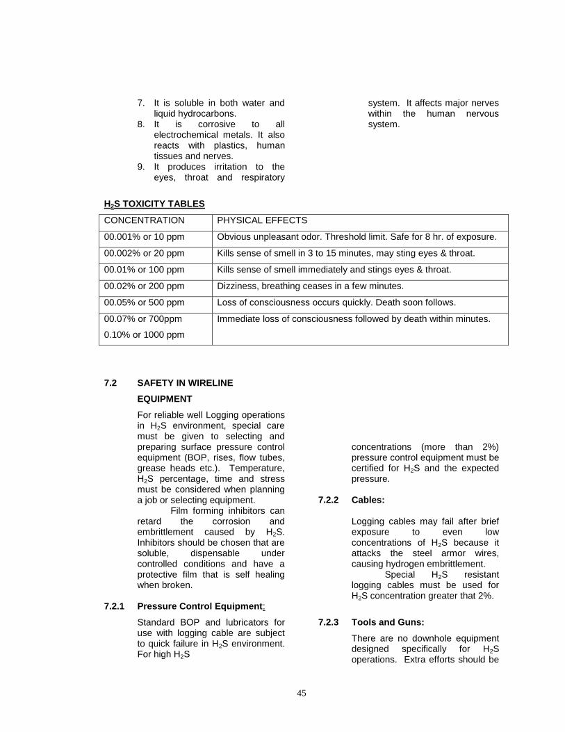
45
7. It is soluble in both water and liquid hydrocarbons.
8. It is corrosive to all electrochemical metals. It also reacts with plastics, human tissues and nerves.
9. It produces irritation to the eyes, throat and respiratory
system. It affects major nerves within the human nervous system.
H2S TOXICITY TABLES
CONCENTRATION PHYSICAL EFFECTS
00.001% or 10 ppm Obvious unpleasant odor. Threshold limit. Safe for 8 hr. of exposure.
00.002% or 20 ppm Kills sense of smell in 3 to 15 minutes, may sting eyes & throat.
00.01% or 100 ppm Kills sense of smell immediately and stings eyes & throat.
00.02% or 200 ppm Dizziness, breathing ceases in a few minutes.
00.05% or 500 ppm Loss of consciousness occurs quickly. Death soon follows.
00.07% or 700ppm
0.10% or 1000 ppm
Immediate loss of consciousness followed by death within minutes.
7.2 SAFETY IN WIRELINE
EQUIPMENT
For reliable well Logging operations in H2S environment, special care must be given to selecting and preparing surface pressure control equipment (BOP, rises, flow tubes, grease heads etc.). Temperature, H2S percentage, time and stress must be considered when planning a job or selecting equipment. Film forming inhibitors can retard the corrosion and embrittlement caused by H2S. Inhibitors should be chosen that are soluble, dispensable under controlled conditions and have a protective film that is self healing when broken.
7.2.1 Pressure Control Equipment:
Standard BOP and lubricators for use with logging cable are subject to quick failure in H2S environment. For high H2S
concentrations (more than 2%) pressure control equipment must be certified for H2S and the expected pressure.
7.2.2 Cables:
Logging cables may fail after brief exposure to even low concentrations of H2S because it attacks the steel armor wires, causing hydrogen embrittlement. Special H2S resistant logging cables must be used for H2S concentration greater that 2%.
7.2.3 Tools and Guns:
There are no downhole equipment designed specifically for H2S operations. Extra efforts should be
46
made in the clean up of tools and guns before and after H2S jobs. Also, an inhibitor should be used.
7.2.4 O-rings and Seals:
Close attention must be given to the proper selection of 0-rings when working in H2S. Use Viton 0-rings and rebuild the logging head after three to four trips downhole.
7.3 OPERATIONS AND LIMITATIONS
The following procedures apply when working in a H2S environment. Items preceded with (*) only apply when standard non H2S certified equipment is used.
a. Insure all personnel assigned to the job are medically qualified, and have completed the required training in H2S and its evacuation.
b. Determine if the H2S safety equipment is present on the rig.
c. If possible, pressure check all pressure equipment to 1.2 times the expected well pressure.
d. (*) Bathe all internal parts of the blow out preventors, rises, well head adapters and stuffing boxes with a solution of inhibitor.
e. Use H2S 0-rings and seals when making up tools and guns.
f. Insure the proper amount of inhibitor has been mixed with the injector grease and line oiler.
g. Check all safety equipment. Verify status of H2S monitors and respiratory equipment. Complete pressure check on all pressure control equipment.
h. Insure bleed off lines are securely chained.
i. After opening the well, feed a continuous stream of inhibited grease into the pressure control equipment to replace any loss during the operation.
j. When bleeding off pressure, insure the operator remains upwind with respiratory equipment downed.
k. Open all tools/guns parts or seals slowly to relieve any trapped pressure. Only back off enough to break the seal.
l. (*) Non-proofed equipment should not be used again for several days to allow the atomic hydrogen to diffuse out. Failure to do this can cause premature failure of equipment.
m. (*) Check cables for possible H2S damage. If damage is indicated, the only safe action is to use another cable until the damaged cable has been properly checked for strength and H2S damage.
n. Off duty sleeping is authorized in the safe area only.
7.4 SAFETY OF PERSONNEL
All personnel likely to be involved with H2S environment operations, must be specially trained in the following:
(a) H2S Characteristics and hazards to personnel and equipment.
(b) Use of H2S detectors and their limitations.
(c) Use of protective (respiratory) equipment and emergency procedures.
(d) Selection, preparation and use of equipment for H2S environment.
(e) Special Operating procedures in H2S environment.
7.4.1 DETECTION OF H2S:
i) H2S detection cannot be relied
upon smell only. ii) Existing H2S detectors may be
fixed-location monitors or attached to the clothing of personnel.
iii) Monitors may be qualitative or quantitative and may use chemical or electronic sensors.
47
iv) Proper detector positioning is critical. Place fixed monitors in low areas where H2S accumulates. Wear the personal detector at waist height.
7.4.2 H2S EMERGENCIES
1. If H2S gas concentration exceeds 20 ppm in air, stop work and don approved respiratory equipment.
2. Leave the area if you are not working.
3. If H2S gas concentration exceeds 50 ppm in air, leave the area immediately unless your assigned job is to contain the emergency. If you stay, you MUST wear approved respiratory equipment.
4. In the event of a sudden release of H2S gas, or if you hear H2S gas release warning signals.
* Hold your breath to avoid
breathing the gas. * Put on protective
equipment. * Help any person in distress. * Leave the area and gather
for muster and a safety briefing.
* Re-enter the area with protective equipment for repairs or to continue operations as appropriate.
5. Emergency priorities MUST be:
(a) Personal safety. (b) Safety of others. (c) Containment of emergency. (d) Completion of operation.
7.4.3 RESCUE AND TREATMENT OF
H2S VICTIMS:
7.4.3.1 RESCUING THE VICTIM:
(a) Ensure your own safety first.
(b) Use respiratory equipment. (c) Check upwind safe area for
sufficient air supply before moving victim.
(d) Check your mark seal before entering a contaminated area.
(e) Use all available aids such as stretches, ropes, slings etc.
(f) Two people can rescue better than one person.
7.4.3.2 REMOVING THE VICTIM:
(a) If possible, use a stretcher or litter, particularly if you suspect internal injuries. If necessary drag the victim towards safety. Do not carry anyone on your shoulder.
(b) Every second is vital after H2S inhalation. Remove the victim as quickly as possible. If the victim has inhaled a lethal amount of H2S, he may have only moments to live, unless adequate first-aid is applied.
7.4.3.3 TREATMENT OF THE VICTIM:
(a) Clear the air passage. (b) If the victim is not
breathing, begin artificial respiration (preferably mouth-to- mouth resuscitation) immediately.
(c) Place victim on a mechanical resuscitator as soon as possible.
(d) Check victim's pulse. If no pulse (heart stopped), begin Cardio-pulmonary (CPR) resuscitation immediately.
(e) If you feel any pulse, no matter how weak, do not give CPR.
48
(f) Control severe bleeding with direct pressure. Arterial bleeding (bright red, usually pulsating) is more serious than bleeding from the veins (less red, smooth flow).
(g) Keep the victim warm, with feet elevated, to prevent shock.
(h) Get medical help as soon as possible. A victim that remains conscious after minor H2S exposures should not work for 24 hours or until it is certain that the reflexes have returned to normal.
GLOSSARY OF TERMS: Radioactivity: A property of unstable isotopes which undergo spontaneous atomic readjustment with the liberation of energy (e.g. alpha or beta particles, or gamma rays). The loss of energy will result in the decay of transformation of the unstable isotope into a stable isotope; or, transmutation into an isotope of another element. Radioactivity log: A well log of natural or induced radiation. Usually refers to a gamma-ray log; but, sometimes the expression radioactivity log is used to refer to a density log, neutron log, or other nuclear logs. Radioisotope: A nuclide. A radioactive isotope (unstable isotope) which spontaneously emits particulate (alpha, beta) or electromagnetic (gamma) radiation as its decay to a stable state. Radioactive source : A radioactive isotope alone or in combination with another element or isotope, hermetically sealed in an encapsulated container used in logging operations to obtain collimated or omni directional radioactivity.
Radio isotope: A radioactive isotope (unstable isotope) which spontaneously emits particles (alpha, beta) or elctromagnetic (gamma) radiation as its decay to a stable state. Radioactive calibrator field verifiers: Resin impregnated with one or more Radio isotopes or collimated capsules used with or without spacers used for field verification of logging tools calibration. Encapsulation: The process of sealing radioactive materials to prevent contamination. Exposure, Film: Radiation intensity multiplied by time. External Discontinuities: Surface irregularities which cause density variation on a radiograph. These are observable with the naked eye. Film Badge: A package of photograph film worn like a badge by workers in the nuclear industry to measure exposure to ionizing radiation. The absorbed dose can be calculated by the degree of film darkening caused by the irradiation. Film Holder: A light-tight carrier for films and screens. Leak Test: A test on sealed sources to ensure that radioactive material is not being released. Maximum permissible Dose (MPD): That does of ionizing radiation which competent authorities have established as the maximum that can be absorbed without undue risk to human health (see also radiation protection guide). Occupational Dose: Includes exposure of an individual to radiation (1) in a restricted area; or (2) in the course of employment in which the individual's duties involve exposure to radiation; provided that "occupational dose" shall not be deemed to include any exposure of an individual to radiation for the purpose of medical
49
diagnosis or medical therapy of such individual. Radiation: The propagation of energy through matter or space in the form of waves. In atomic physics the term has been extended to include fast-moving particles (alpha and beta rays, free neutrons, etc.). Gamma rays and x-rays, of particular interest in atomic physics, are electromagnetic radiation in which energy is propagated in packets called photons. Radiation Area: Means any area, accessible to personnel, in which there exists radiation, originating in whole or in part within licensed material, at such levels that a major portion of the body could receive in any one hour a dose in excess of 5 mRem, or in any 5 consecutive days, a dose in excess of 100 mRem. Radiation Safety Officer: An individual engaged in the practices of providing radiation protection. He is the representative appointed by the licensee for liaison with the Atomic Energy Commission. Radioactive material: Includes any such material whether or not subject to licensing control by the Commission. Sealed Source: Means any by-product material that is encased in a capsule designed to prevent leakage or escape of the by-product material. Survey Meter: A portable instrument which measures dose rate of exposure or radiation intensity. Waste, Radioactive: Equipment and materials (from nuclear operations) which are radioactive and for which there is no further use. SIEVERT: is the new unit of measurement of radioactivity and defined as 1 joule per kilogram. 1 sievert is equal to 100 rems. CURIE: is the unit of measurement of radioactivity which is equal to 3.7 x 10 dis-integration per second.
WIPE TEST: To check possible leak of radioactive source a WIPE TEST is conducted. The procedure is detailed below.
1. Clear the immediate area of all personnel not essential to the test procedure.
2. Moisten a filter paper with solox, alcohol or other suitable solvent, just before making the wipe.
3. Rub the filter paper over the designated wipe test area of the source.
4. Put back source in its designated container.
5. Place the wipe inside the glassine envelope and hold it firmly against the associated down-hole tool opposite the mid point of detector or appropriate survey meter. During this procedure capsule is exposed without shielding of any kind. Time & Distance factors are extremely important.
6. Following the procedure wash the hands throughly.
MINITRON TUBES: A minitron tube is a particle accelerator that yields 14 Me V neutrons when it is operating. The minitron tube contains deuterium and tritium, which are absorbed onto the tube. When a short duration control pulse is applied to a ring magnet surrounding the gases, the gases are ionized. At the same time, a high negative voltage is applied to a target located at the other end of the tube. The positive ions produced by the deuterium and tritium bombard the target, generating a nuclear reaction. These tubes are used in Pulsed Neutron type down-hole tools and need recharging after 100 - 120 hours of operation PIP TAGS: PIP tags are made of 60 Cobalt, which is primarily a gamma emitter. PIP tags are used to identify area within the well bore. A PIP tag is put on a perforating charge. When the charge is shot, the radioactive material is deposited in the formation. The radioactive material can later
50
be detected, allowing the location of the perforating shots to be pin-pointed. References: 1. Halliburton Logging Services Inc.
“International Safety Manual No. HLS-SAF-17/ED.1 Rev. 1”, on Well Logging Services.
2. Safety with Hydrogen Sulfide (H2S)” by
Gearhart Wireline Services” Fortworth, Texas.
3. Manuals on Safety in Well Logging of
Schlumberger Asia Services Ltd. 4. “Safety Aspects during Logging
(Handling of Explosives and Radioactive Sources)” by S.Madhavan et al., Well Logging, MRBC, Mumbai.
5. “Radiological Safety in Handling Nuclear
Logging Devices”, Lectures by Directorate of Radiological Protection, MRBC, Mumbai.
6. “Radiological Safety in Radioactive Well
Logging”, by O.P.Massand, Division of Radiological Protection, MRBC, Mumbai.
7. Welex “Standard Procedures for
Handling Radioactive Materials”, OP-5002.
8. Document on “Classification of
Dangerous Goods”, Published by IATA. 9. “Review of Safety and Security Aspects
of Explosives and Detonators used in Well Logging Activities, a Task Force Report by B.K.Bose, et. al., ONGC, Mumbai, December 1993.
10. “Explosives Safety in Well Logging
Operation”, by Institute of Petroleum Safety and Environment Management (IPSEM), ONGC, Goa , Feb.'96.
11. MGM “Maximum Radiation Standards”.
12. “Recommended Practices of Oil Field Explosives Safety”, API Recommended Practices 67 (RP 67), March 1994, API Exploration and Production Department, Dallas, Texas, USA.
13. “Safety in Use of Explosives in ONGC
Wireline Logging Operations”, a Task Force Report by Dr.K.L.Goel, P.V.Raman Rao, et.al., May 1994.
14. The Explosive Act,1884 alongwith
Explosive Rule,1983.
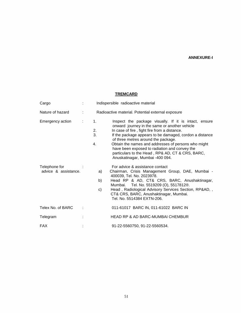
51
ANNEXURE-I
TREMCARD Cargo : Indispersible radioactive material Nature of hazard : Radioactive material. Potential external exposure Emergency action : 1. Inspect the package visually. If it is intact, ensure
onward journey in the same or another vehicle 2. In case of fire , fight fire from a distance. 3. If the package appears to be damaged, cordon a distance
of three metres around the package. 4. Obtain the names and addresses of persons who might
have been exposed to radiation and convey the particulars to the Head , RP& AD, CT & CRS, BARC, Anuskatinagar, Mumbai -400 094.
Telephone for : For advice & assistance contact advice & assistance. a) Chairman, Crisis Management Group, DAE, Mumbai -
400039, Tel. No. 2023978. b) Head RP & AD, CT& CRS, BARC, Anushaktinagar,
Mumbai. Tel. No. 5519209 (O), 5517812®. c) Head , Radiological Advisory Services Section, RP&AD, ,
CT& CRS, BARC, Anushaktinagar, Mumbai. Tel. No. 5514384 EXTN-206. Telex No. of BARC : 011-61017 BARC IN, 011-61022 BARC IN Telegram : HEAD RP & AD BARC-MUMBAI CHEMBUR FAX : 91-22-5560750, 91-22-5560534.