Embed Size (px)
Citation preview

OPS Installation
Oil Purification Systems, Inc.
Installation Instructions For
Cummins ISX
Document Part Number I-00x
Document Edition Number 1.0
Edition Release Date July 2007


OPS Installation
Copyright © 2007 Page 1
Table of Contents Safety Precautions ........................................................................................................................2
General Precautions......................................................................................................................2
Notes for all Hose Connections:....................................................................................................2
Before Installing This System........................................................................................................2
Technical Support ....................................................................................................................... 2
Parts Identification ....................................................................................................................... 3
Section 1 – Mounting the Evaporator .......................................................................................... 5
Section 2 – Mounting the Filter .................................................................................................... 6
Section 3 – Supply and Return Line Hoses.................................................................................. 8 Hose Specifications ............................................................................................................ 8 Accessing the Supply Port ................................................................................................. 8 Accessing the Return Port .................................................................................................. 8 Connecting the Oil Source to the Filter .............................................................................. 9 Connecting the Filter to the Evaporator .............................................................................. 9 Connecting the Evaporator Return Line ............................................................................. 9 Venting the Evaporator ..................................................................................................... 10
Section 4 – Adjusting the Metering Valve................................................................................... 11
Checking and Adjusting the Flow Rate ............................................................................ 11
Section 5 – Electrical Connections ............................................................................................ 14
Procedure ......................................................................................................................... 15
Warranty .................................................................................................................................... 17
______________________________________________________________________
Copyright Notice: Copyright © 2006 Oil Purification Systems, Inc. All Rights Reserved. OPS-1 is a trademark of Oil Purification Systems, Inc. OPS-1 Patented 6,287,455. Patents Pending in the United States and other countries. Other trademarks and trade names that may be used in this document to refer to either entities claiming the marks and names or their products, OPS disclaims any proprietary interest in trademarks and trade names; such marks and names are owned by their respective holders.

OPS Installation
Copyright © 2007 Page 2
Safety Precautions • Before beginning work, ensure the engine has sufficiently cooled to prevent burn
injuries. _____________________________________________________________________
General Precautions • Ensure the voltage of the system being installed (12V or 24V) matches that of the truck.
_____________________________________________________________________
Notes for all Hose Connections: • Use a heat gun or soak the hose ends in hot water to expand them to ease
assembling hoses over barbed fittings. Be sure to shake off any water from the hoses.
• Apply light oil such as silicon spray or WD40 inside the hose end to ease the assembly of the adaptor into the hose end. DO NOT use grease or engine oil for this purpose.
• Slide a ½” hose over each ¼” hose at those places where the hose comes close to moving or vibrating parts. This is to protect the ¼” hose from abrasion. Also add the ½” hose to the parts of the hose that bend. This will help the ¼” hose hold its shape and prevent crimping.
• Route all hoses away from extremely hot components, such as exhaust pipes and the turbos.
• Route all hoses away from moving parts, such as the radiator fan.
• Use ties to secure the hoses in place.
• Ensure the hose is the proper length before sliding them over the barbed hose fittings, as hoses must be cut to be removed from the fittings.
• Leave a slight amount of slack in the hose to allow for engine vibration.
• Use teflon tape on all NTP threads (used on the hose adaptors). _____________________________________________________________________
Before Installing This System
It is recommended that you perform an oil change on the vehicle before installing this system.
• Be sure to handle used oil in compliance will all applicable laws. This will usually include making provisions for recycling.
• Always wear oil resistant gloves when handling used oil. _____________________________________________________________________
Technical Support ...........................................................Call Toll Free (866) OILPURE

OPS Installation
Copyright © 2007 Page 3
Parts Identification The major components of this system are the Filter and the Evaporator. These are shown in the following illustrations.
The Filter
Figure 1 – The Filter Assembly
Filtration Head Top Nut
Oil Filter Canister
Filtration Head
Return Port – Sends Pressurized Oil to the Evaporator
Oil Shut-off Valve
Supply Port –
Receives pressurized oil
from the engine.
Oil Filter Element (inside the
canister)
Sampling Valve
Safety Cap
Oil Filter Serial Number (Refer to this when calling for Tech Support)

OPS Installation
Copyright © 2007 Page 4
The Evaporation Chamber
Figure 2 – The Evaporator Assembly
Evaporator Top
Return Port –
Gravity feeds oil back to
engine.
Metering Valve –
Controls flow of oil into Evaporator
from Filter.
Heating Element Power
Supply Wire
Heating Element Ground Wire
Vent Barb – Attachment point
for Vent Hose
Check Valve
OPS Installation
Copyright © 2007 Page 5
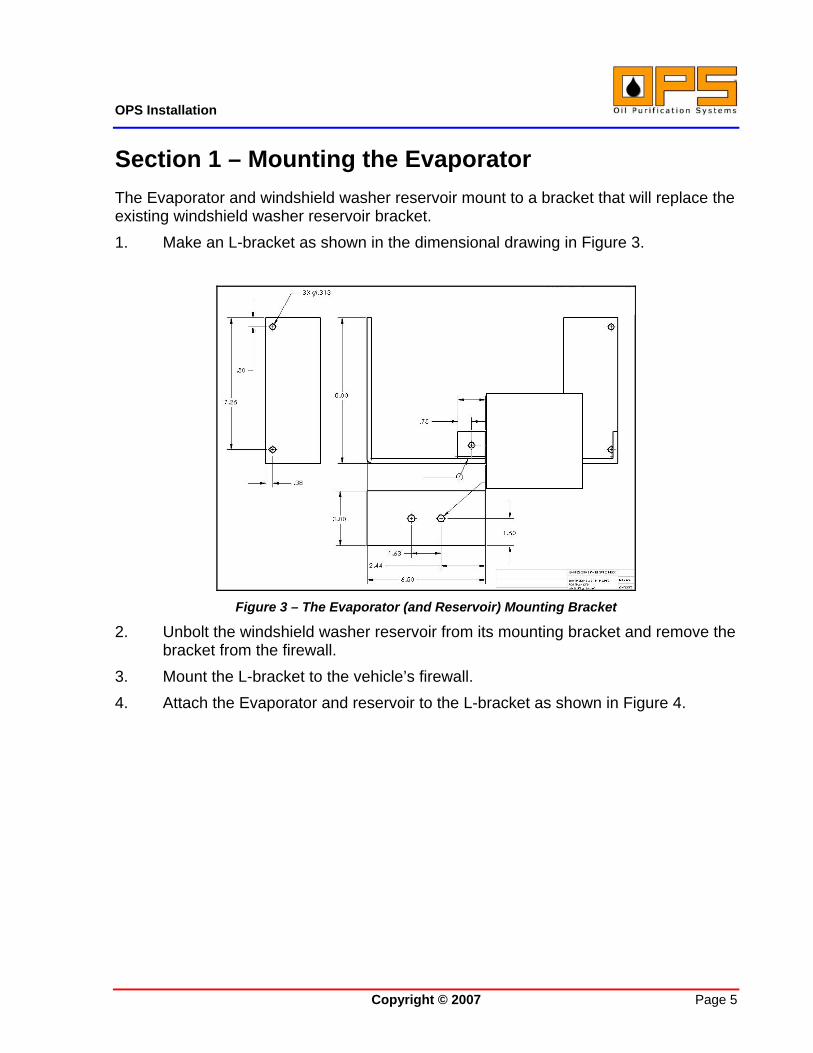
Section 1 – Mounting the Evaporator The Evaporator and windshield washer reservoir mount to a bracket that will replace the existing windshield washer reservoir bracket. 1. Make an L-bracket as shown in the dimensional drawing in Figure 3.
Figure 3 – The Evaporator (and Reservoir) Mounting Bracket
2. Unbolt the windshield washer reservoir from its mounting bracket and remove the bracket from the firewall.
3. Mount the L-bracket to the vehicle’s firewall. 4. Attach the Evaporator and reservoir to the L-bracket as shown in Figure 4.

OPS Installation
Copyright © 2007 Page 6
Figure 4 – The L-Bracket

OPS Installation
Copyright © 2007 Page 7
Section 2 – Mounting the Filter The Filter is bolted directly to the vehicle’s frame rail, on the driver’s side.
1. Position the Filter on the outside of the driver’s side frame rail as shown in Figure 5.
Figure 5 – Mounting the Filter
2. Use the Filter mounting bracket as a template to mark the frame rail for drilling. (NOTE: Place a strip of masking tape on the frame rail to make it easier to mark for drilling.)
IMPORTANT NOTE: Before drilling into the frame, check inside the frame rail for hoses or wiring that may be routed there. If hoses or wiring are present, move them out of the way or select a different location on which to mount the filter.
3. Drill the Filter mounting holes and use the 5/16” hardware provided to attach the Filter to the frame.

OPS Installation
Copyright © 2007 Page 8
Section 3 – Supply and Return Line Hoses Hose Specifications
• ¼” hose, use Parker 836 high temperature push lock hose, or the equivalent.
• ½” hose, use Parker 801 general purpose push lock hose, or the equivalent.
Accessing the Supply Port: 1. Remove the pipe plug from the oil filter mount. 2. Install a hose adapter to replace the plug that was removed.
Accessing the Return Port: 1. Remove the oil drain plug from the oil pan. 2. Install the hose adaptor to replace the oil drain plug. See Figure 6.
Figure 6 – Location of Oil Return Port

OPS Installation
Copyright © 2007 Page 9
Connecting the oil source to the Filter: 1. Measure the distance from the fitting on the oil filter mount to the source side of
the filter. Run the tape measure along the same route you will use for this hose. Add 1.5 – 2.0 inches to accommodate engine vibration.
2. Cut the hose to length. 3. Slide the ¼” hose over the supplied ¼” barbed hose fitting. 4. Screw the hose fitting into the adapter already attached to the engine. 5. Slide the other end of the hose to the hose fitting that will go into the filter shut off
valve. 6. Attach the second hose fitting onto the shut off valve on the side of the filter
housing. Connecting the Filter to the Evaporator:
1. Measure the distance from the return port on the filter to the source port on the evaporator. Run the tape measure along the same route that the hose will follow. Add 1.5 to 2” slack for engine vibration.
2. Insert the hose fittings into each end of the hose.
3. Attach one fitting into the return side of the filter and the other to the source side of the evaporator.
Connecting the Evaporator Return Line:
1. Measure the distance from the hose adaptor on the oil pan to the return port on the evaporator. Run the tape measure along the same route you will use for this hose. Add 1.5 – 2.0 inches to accommodate engine vibration.
2. Cut the hose to length.
3. Slide the hose end over the fitting that will attach to the adaptor you just screwed into the oil pan.
4. Attach the fitting that will go into the return side of the evaporator into the other end of the hose.
5. Route the second end of the hose next to the return side of the evaporator, and attach it to the evaporator.

OPS Installation
Copyright © 2007 Page 10
Venting the Evaporator: 1. Route the hose from the top of the Evaporator to just in front of the mud flap, as
shown in Figure 7.
Figure 7 – Venting Hose Termination

OPS Installation
Copyright © 2007 Page 11
Section 4 – Adjusting the Metering Valve The flow rate from the Filter to the Evaporator must be adjusted for each application. The recommended flow rate is 1-2 gallons per hour (2.1 – 4.3 ounces per minute).
Checking and Adjusting the Flow Rate:
1. Open the Oil Shut-off Valve on the Filter. See Figure 8.
Figure 8 – Location of Shut-off Valve on the Filter
2. Start the engine and allow it to warm up to normal operating temperature and set the engine speed to 2,000 RPMs or the “normal operating” speed of the engine.
3. Check for leaks. If there are any, shut off the engine, repair the leaks, and restart the engine.
4. Close the Oil Shut-off Valve on the Filter.
Oil Shut-off Valve

OPS Installation
Copyright © 2007 Page 12
Figure 9 – Location of Vapor Escape Port
5. Close the metering valve and remove it from the Evaporator.
6. Open the Oil Shut-off Valve on the Filter.
7. With an oil catch pan under the metering valve, open the metering valve all the way for several seconds and allow the full oil flow to flush out the oil lines.
8, Close the metering valve all the way.
9. Open the metering valve about 1-1/2 turns.
10. Check the flow rate in ounces per minute to verify it is between 2.1 and 4.3. • If this rate is not being met, open or shut the metering valve until this rate is
attained. • Allow several minutes between each adjustment before taking the rate sample.
11. When the metering valve is correctly adjusted, use the supplied allen wrench to lock in the adjustment and then shut down the engine.
Vapor Escape Port
Metering Valve

OPS Installation
Copyright © 2007 Page 13
12. Close the Shut-off valve on the Filter.
13. Reattach the metering valve to the Evaporator.
14. Using thread tape, tighten the elbow fitting to the top of the Evaporator.
15. Attach a vent hose to the vapor escape port on the top of the Evaporator.
16. Open the Shut-off valve on the Filter.
17. Restart the engine and check for leaks. Fix any leaks as necessary.

OPS Installation
Copyright © 2007 Page 14
Section 5 – Electrical Connections Power for the Evaporator is taken from an open circuit on the fuse panel.
Notes: • Ensure the voltage of the truck matches the voltage of the system you are
installing. o Evaporators with BLACK conductors are for a 12V system. o Evaporators with WHITE conductors are for a 24V system.
• Use wire ties to secure all wires away from moving parts or extreme heat.
• Ensure the alternator has enough power to handle the additional load.
• Use the supplied 15 amp fuse and fuse holder to protect the circuit.
Important:
• Select a spare (unused) circuit from the fuse panel, as using a computer-controlled circuit may cause error codes to display.
• Ensure the circuit select is “keyed”; that is, powered on only when the engine is running and not powered when the key is in the “accessory” or “off” position.

OPS Installation
Copyright © 2007 Page 15
Procedure
There are two wires sticking out from the top of the Evaporator.
1. Connect the ground wire to a suitable ground, such as the mounting bolts for the Evaporator.
2. Connect the power lead to a 15 amp accessory circuit in the fuse box. See Figure 10.
Figure 10– Electrical Connections

OPS Installation
Copyright © 2007 Page 16
3. Install a 15 amp fuse into the fuse box for the circuit used for the Evaporator. See Figure 12.
Figure 12 – Installing the Fuse

OIL PURIFICATION SYSTEMS, INC. Five (5) Year Limited Warranty
OPS-1 is a trademark of Oil Purification Systems, Inc. Copyright © 2006, Oil Purification Systems, Inc. All Rights Reserved. OPS-1 Patented 6,287,455. Patents Pending in the United States and other countries USA Rev. 20060715 Page 17
Oil Purification Systems, Inc. (“OPS”) warrants that OPS-1 shall be free from defects in materials and workmanship, and will substantially conform to its specifications for a period of five (5) years after the date of purchase (the “Period”), provided OPS-1 is properly installed, operated, and maintained, and, in each instance, in accordance with the documentation. Should OPS-1 have been found and demonstrated to be defective during the Period for the reasons covered by this Limited Warranty, OPS, at its option, shall:
1. REPAIR OPS-1 or part thereof; or 2. REPLACE OPS-1 or part thereof.
In the event of a discrepancy between any purchase order accepted by OPS and this warranty, the terms of this warranty apply. OPS reserves the right to use either new, used, or refurbished parts. This Limited Warranty does not cover any damages caused by you or due to external causes, including any act of God, natural disaster, accident, flood, war, sabotage, terrorism, military actions, or problems with the engine, e.g., failure to maintain the engine in accordance with its documentation (other than manufactures recommended oil changes). OPS does not warrant that OPS-1 will be free from design defects or errors. To request warranty service from OPS, you need to contact OPS within five (5) calendar days following discovery of the defect or damage at the following telephone number: (866) OIL-PURE; or address:
Oil Purification Systems, Inc. One Reservoir Corporate Centre 4 Research Drive Shelton, Connecticut 06484; and
return OPS-1 or the defective part for inspection, including in such package a copy of the applicable warranty card, a detailed description of the problem, proof of purchase, and detailed records associated with the installation and maintenance of OPS-1 and the engine, and such other information as requested by OPS. THESE WARRANTIES REPLACE ALL OTHER WARRANTIES, EXPRESS OR IMPLIED, INCLUDING, BUT NOT LIMITED TO, THE IMPLIED WARRANTIES OF MERCHANTABILITY, NON-INFRINGEMENT, AND FITNESS FOR A PARTICULAR PURPOSE. THESE REMEDIES ARE THE SOLE AND EXCLUSIVE REMEDIES FOR ANY BREACH OF WARRANTY AND ONLY APPLY TO USE OF OPS-1 IN THE UNITED STATES OF AMERICA, THE ORIGINAL PURCHASER FOR THE SPECIFIC ENGINE IDENTIFED ON THE WARRANTY CARD, AND ONLY LASTS FOR AS LONG AS SUCH PURCHASER OWNS OPS-1 AND THE APPLICABLE ENGINE. OPS IS NOT RESPONSIBLE FOR ANY COST OF REMOVAL AND INSTALLATION, AND ANY INDIRECT, SPECIAL, PUNITIVE, INCIDENTAL, OR CONSEQUENTIAL DAMAGES RESULTING FROM ANY BREACH OF WARRANTY OR UNDER ANY OTHER LEGAL THEORY, INCLUDING, BUT NOT LIMITED TO, LOST PROFITS, DOWNTIME, GOODWILL, DAMAGE TO OR REPLACEMENT OF EQUIPMENT AND PROPERTY USED WITH OPS-1. SOME JURISDICTIONS DO NOT ALLOW THE EXCLUSION OR LIMITATION OF IMPLIED WARRANTIES, INCIDENTIAL OR CONSEQUENTIAL DAMAGES, SO THE ABOVE LIMITATIONS OR EXCLUSIONS MAY NOT APPLY TO YOU. IF ANY OF THESE LAWS APPLY, THEN ANY EXPRESS OR IMPLIED WARRANTIES ARE LIMITED IN DURATION TO THE LIMITED WARRANTY PERIOD. NO WARRANTIES APPLY AFTER THAT PERIOD. IN ANY EVENT, OPS’S MAXIMUM LIABILITY SHALL NOT EXCEED THE PRICE RECEIVED BY OPS FOR OPS-1 THAT IS SUBJECT TO THIS LIMITED WARRANTY. THIS LIMITED WARRANTY GIVES YOU SPECIFIC LEGAL RIGHTS, AND YOU MAY ALSO HAVE OTHER RIGHTS THAT VARY FROM JURISDICTION TO JURISDICTION.