Embed Size (px)
Citation preview
2010 Edition | Introduction | Page I
OIL FIRED APPLIANCE & SYSTEM INSTALLATION REQUIREMENTS
Design, Operating Principles and Energy Efficiency
Foreword This publication is one in a suite of technical books provided by OFTEC to assist those involved in oil delivery, installation &/or maintenance of equipment to understand the practices, principles and safety requirements of their work. OFTEC technical books can also be used as reference material for designers and specifiers of oil equipment and support technicians during OFTEC training & assessment and assist them whilst out in the field. Oil fired fixed combustion appliances and heating systems are inherently safe when installed in accordance with industry codes of practice, manufacturer’s instructions and statutory requirements. This book contains guidance on means of achieving safe and compliant installation. Small bore central heating systems have been in common use since the 1960’s. The majority of systems were well designed and installed, and are still giving good service. However, some systems have design faults and the degree of control provided is not always sufficient to meet current requirements for energy conservation. Understanding the basic principles of heating system design enables technicians to design efficient new systems and update the older ones. The attainment of the highest possible levels of fuel economy is now accepted as being vitally important in combating climate change. This book contains a great deal of information regarding measures that can be taken to reduce fuel use, whilst maintaining comfort by the use of good design and modern components. The information contained within this publication has been drafted using generic practices that are generally applied throughout the UK, Channel Islands, Isle of Man and the Republic of Ireland. However, in some regions more onerous legislative requirements apply and are summarised in Section 6. Scope OFTEC Technical Book 4 gives guidance on installation requirements for fixed combustion appliances and associated small bore wet central heating systems, using liquid fuels to BS 2869 (Class C2 Kerosene and Class D Gas oil), bio liquids to EN 14214 and bio liquid/mineral fuel blends to OPS 24. Fuel conservation measures are also identified. For an overall understanding of both old and new systems it is recommended that this publication is read together with the CIBSE ‘Domestic Heating Design Guide’. Technicians intending to install/maintain underfloor heating circuits or solar thermal installations should also consider obtaining CIBSE publications, ‘Underfloor Heating Design & Installation Guide’ and ‘Solar Heating Design & Installation Guide’ CIBSE publications are available from OFTEC Direct – 0845 65 85 080 or www.oftecdirect.com.
AMD 04-1214-33

Page II | Introduction | 2010 Edition
This publication has been compiled into Sections as follows. Section 1 – Oil appliances up to 45kW output Requirements, materials and equipment associated with installation of oil fired appliances up to 45kW Output Section 2 – Oil appliances above 45kW output Requirements, materials and equipment associated with the installation of oil fired appliances above 45kW Output Section 3 – Domestic Heating Systems Requirements and practices associated with the installation of new, or the upgrading of existing small bore hot water and space heating systems Section 4 – Fuel Conservation Measures Measures to promote fuel and energy conservation in buildings. Section 5 – OFTEC Procedures Procedures that technicians should implement into their everyday work in order to meet legislative requirements in the production and distribution of information relating to work carried out. Section 6 – Regional Requirements A summary of requirements specific to individual regions of the UK, Channel Islands, Isle of Man and the Republic of Ireland which take precedence over the generic guidance contained within this publication. © Copyright The Copyright of this publication rests in OFTEC. All rights reserved. This document and its information is supplied without liability for errors or omission and no part may be reproduced, used or disclosed except as authorised by Contract or other written permission.

2010 Edition | Introduction | Page III
OFTEC The Oil Firing Technical Association (OFTEC) was formed in April 1991 with the aim of improving standards within the oil firing industry and to make available information, tools, equipment and products to enable all concerned to carry out their functions compliantly. The Members of the Association are made up of representatives from oil companies, oil distributors, manufacturers of equipment and training & assessment centres utilised by the oil firing industry in the United Kingdom, Channel Islands, Isle of Man and the Republic of Ireland. In addition to OFTEC’s activity as a trade association, OFTEC operates a ‘Competent Persons Register’. This allows technicians that undergo training and assessment in the installation of different heating technologies to apply for registration in order to self-certify their installation work, as required by some regional Building Regulations. OFTEC currently offers registration with regard to oil, heat pumps, solar thermal, unvented hot water, and electrical installation work. See www.oftec.org for further developments in the registration area. Through the OFTEC trade association, an important aspect of work is the testing, approval and certification of oil firing equipment. A scheme for this is operated under the name of OFCERTTM. OFCERTTM is an integral part of OFTEC’s mission to promote excellence in oil fired heating and cooking. Specifiers and users of OFCERTTM licensed oil firing equipment can be sure that it exceeds the latest standards of manufacturing and legislation. Equally, because OFCERTTM is the dedicated testing and certification scheme for oil firing equipment, it gives added prestige to the high standards of manufacture within the industry. OFTEC Member Independent Test Houses carry out testing to OFCERTTM requirements. Each Test House must have UKAS or ILAB approved test procedures and they are consulted with regard to the development of OFCERTTM Standards. Manufacturers can apply for OFCERTTM approval for their own test facilities as Auxiliary Test Facilities, providing they meet stringent criteria including UKAS or ILAB approval for their operations. Testing at Auxiliary Test Houses is usually required to be supervised by an appropriate Main Test House. Main Test Houses are first class independent or government laboratories. A full list of current test houses can be found in the OFTEC Equipment Directory/Specifiers Guide. The OFTEC Directory (Specifiers Guide) is a valuable resource for specifiers and users of oil firing equipment. Updated regularly, the Directory is available online and contains comprehensive details of oil firing and associated equipment. It also shows which products have obtained OFCERTTM licences, along with details of relevant European Standards and Directives. Copies of the relevant OFTEC Standards together with application forms are available to order from OFTEC. OFCERTTM licences are awarded to equipment that has satisfied the requirements of an OFTEC Standard and is produced to a Quality Assurance scheme incorporating that standard. The scheme is operated under the overall supervision of the OFCERTTM Scheme Committee. This is one of many OFTEC publications. For a complete listing please visit the publications section at www.oftec.org.
AMD 04-1214-33

Page IV | Introduction | 2010 Edition
TECHNICAL UPDATES Due to developments in technology and changes in building regulations, OFTEC will from time to time issue updates to this publication to maintain its accuracy. OFTEC technicians can obtain updates as free of charge downloads from the OFTEC website www.oftec.org as a benefit of registration. Printed copies can be obtained from OFTEC on request and a charge may be levied for this service. So that latest information is held and can be referred to, it is recommended that registered technicians take advantage of free technical updates, which should be printed and inserted into this publication. The table below has been provided to record updates to this publication and may be viewed as part of an OFTEC inspection as evidence that a technician is aware of latest changes in industry. The first line of the table is completed as an as example of the information required.
Update Reference Date of Update Page Reference
AMD 04-0910-01 09/09/2010 Section 1, Page 48
AMD 04-1210-02 20/12/2010 Section 6, Pages 3 to 5
AMD 04-1210-03 20/12/2010 Section 3, Page 64
AMD 04-1210-04 20/12/2010 Contents, Pages XI to XVII
AMD 04-1210-05 20/12/2010 Section 6, Pages 34 to 41
AMD 04-1210-06 20/12/2010 Section 5, Pages 6 and 8
AMD 04-1210-07 20/12/2010 Section 6, Pages 13 to 15
AMD 04-1210-08 20/12/2010 Section 6, Pages 23 to 26
AMD 04-1210-09 20/12/2010 Section 1, Page 35
AMD 04-1210-10 20/12/2010 Section 1, Page 43
AMD 04-1212-11 03/12/2012 Section 6, Page 31
AMD 04-1212-12 03/12/2012 Contents, Pages XIV to XV
AMD 04-0413-13 25/03/2013 Section 1, Page 24
AMD 04-0413-14 25/03/2013 Section 1, Pages 50, 52 and 53
AMD 04-0413-15 25/03/2013 Section 2, Pages 11 and Pages 13 to 18
AMD 04-0413-16 25/03/2013 Section 2, Pages 21 to 23
AMD 04-0413-17 25/03/2013 Section 5, Page 11
AMD 04-0413-18 25/03/2013 Section 5, Pages 13 to 16 and Pages 18 to 24
AMD 04-0413-19 25/03/2013 Section 6, Pages 10 to 11
AMD 04-0413-20 25/03/2013 Section 6, Pages 20 to 21
AMD 04-0413-21 25/03/2013 Contents, Pages VIII to XVII
AMD 04-0513-22 13/05/2013 Section 6, Page 10
AMD 04-0913-23 16/09/2013 Section 5, Page 11
AMD 04-0913-24 16/09/2013 Section 6, Pages 22 to 26
AMD 04-0913-25 16/09/2013 Contents, Page XIV
AMD 04-0214-26 01/02/2014 Section 6, Pages 2 to 6
AMD 04-0214-27 01/02/2014 Section 6, Pages 12 to 16
AMD 04-0214-28 01/02/2014 Section 6, Pages 22 to 26
AMD 04-0214-29 01/02/2014 Contents, Pages XIII to XIV
AMD 04-0714-30 21/07/2014 Section 2, Pages 2 to 3
AMD 04-0814-31 22/08/2014 Section 6, Pages 32 to 33
AMD 04-0814-32 22/08/2014 Contents, Pages XIV to XVII
AMD 04-1214-33 12/01/2015 Various (BS 5410-1 Update)
AMD 04-1214-34 12/01/2015 Section 6, Pages 40 to 45
Version 11

2010 Edition | Contents | Page XV
6.7.8 Contact Details .................................................................................................... 37
6.8 Guernsey .................................................................................................................. 38
6.8.1 Guernsey Approved Documents ......................................................................... 38 6.8.2 Control of Building Work...................................................................................... 38 6.8.3 Work Notification ................................................................................................. 38 6.8.4 Minimum Provision for New Systems in New Dwellings ...................................... 38 6.8.5 Minimum Provisions for New or Replacement Systems in Existing Dwellings ..... 39 6.8.6 Electrical Works .................................................................................................. 39 6.8.7 Contact Details .................................................................................................... 39
6.9 Isle of Man ................................................................................................................ 40
6.9.1 The Building Regulations 2014............................................................................ 40 6.9.2 Statutory Documents ........................................................................................... 40 6.9.3 Work Notification ................................................................................................. 41 6.9.4 Minimum Provisions for Domestic Systems ......................................................... 41 6.9.5 Minimum Provisions for Non-Domestic Systems ................................................. 43 6.9.6 Carbon Monoxide Detection ................................................................................ 44 6.9.7 Electrical Works .................................................................................................. 44 6.9.8 Contact Details .................................................................................................... 44
SECTION 1 DIAGRAMS AND TABLES Diagram 1 Condensing Boiler (Example 1) ..................................................................... 3 Diagram 2 Condensing Boiler (Example 2) ..................................................................... 3 Diagram 3 Flue Gas Temperatures from Standard and Condensing Appliances ........... 4 Diagram 4 Human Plume ............................................................................................... 5 Diagram 5 Condensate to Stack ..................................................................................... 7 Diagram 6 Condensate to Waste Pipe ........................................................................... 8 Diagram 7 Condensate to a Soakaway ........................................................................... 9 Diagram 8 Condensate to External Drain ....................................................................... 9 Diagram 9 Vaporising Range Cooker .............................................................................. 11 Diagram 10 Pressure Jet Range Cooker Boiler ................................................................ 12 Diagram 11 Roomheater (Stove) ...................................................................................... 13 Diagram 12 Oil Fired Appliance Flue Gas, Casing and Hearth Temperatures ................. 14 Diagram 13a Chimney and Flue Definitions ........................................................................ 18 Diagram 13b Chimney and Flue Definitions ........................................................................ 19 Diagram 13c Chimney and Flue Definitions ........................................................................ 20 Diagram 14 How Chimneys Work ..................................................................................... 22 Diagram 15a The General Effect of Wind Pressure on Various Types of Buildings ........... 23 Diagram 15b Vaporising Appliance Flue Terminal Guidance (Pitched Roof) ...................... 24 Diagram 15c Vaporising Appliance Flue Terminal Guidance (Flat Roof) ............................ 24 Diagram 16 Flue Draught Stabiliser .................................................................................. 25 Diagram 17 The Separation of Combustible Material from Factory Made Insulated Metal Chimneys meeting BS EN 1859 .................... 32 Diagram 18 Bends Permitted for Flue Offsets ................................................................... 36 Diagram 19 Vertical Balanced Compartment Flue ............................................................ 42 Diagram 20a Clearances advised by British Standard BS 5410 Part 1 ............................... 44 Diagram 20b Separation between a Boundary and Terminal at Right Angles .................... 46 Diagram 21 Condensing Appliance Flue Termination Recommendations ........................ 48
AMD 04-1214-33
Page XVI | Contents | 2010 Edition
Diagram 22a Free Area of Grilles are cm2 per kW of Appliance Maximum Rated Output .. 51 Diagram 22b Free Area of Grilles are cm2 per kW of Appliance Maximum Rated Output .. 52 Diagram 23 Free Area of Grilles are cm2 per kW of Appliance Maximum Rated Output .. 53 Diagram 24 Example Layout Details for a Vaporising Oil Fired Appliance and Extraction Fan ........................................................................ 56 Diagram 25 Example Layout Details for a Pressure Jet Oil Fired Appliance and Extraction Fan ........................................................................ 56 Table 1 Chimney Pressure Designation....................................................................... 29 Table 2 Examples of Chimney Designations................................................................ 30 Table 3 Safety Installation Requirements for Factory Made Insulated Metal Chimneys serving Oil Fired Boilers ........................................... 31 Table 4 Safety Installation Requirements for Flue Pipes serving Oil Fired Boilers discharging Flue Gas Temperatures Below 250°C ................ 33 Table 5 Materials for Flue Pipes and Chimneys for Oil Fired Appliances ...................... 34 SECTION 2 DIAGRAMS AND TABLES Diagram 26 Fuel Application ............................................................................................. 2 Diagram 27 Cast Iron Sectional Boiler .............................................................................. 6 Diagram 28 Warm Air Heater ........................................................................................... 9 Diagram 29 Air Supply Requirements for Open Flued Appliance(s) ................................. 17 Diagram 30 Air Supply Requirements for Balanced Flued Appliance(s) .......................... 18 SECTION 3 DIAGRAMS AND TABLES Diagram 31 General Arrangement of a Domestic Central Heating System ...................... 3 Diagram 32 Heating System Component Names .................................................................. 4 Diagram 33a Static Heads at Different Points on the Circuit ................................................... 8 Diagram 33b Circuit Pressures with Pump Flow ...................................................................... 8 Diagram 33c Circuit Pressures with Pump in Return .......................................................... 9 Diagram 34 Static Head and Open Safety Vent Pipe ........................................................ 11 Diagram 35 Close Coupled Open Safety Vent Pipe and Feed and Expansion Pipe ........ 12 Diagram 36a Feed Path Through By-Pass ......................................................................... 13 Diagram 36b Feed Path Through (Mid-Position) Diverter Valve ......................................... 13 Diagram 37 Sealed Systems ............................................................................................. 14 Diagram 38 (Historical) Heating System with Gravity Primary Circulation ........................ 27 Diagram 39 (Historical) Provision of Independent Space & DHW Temperature Control Whilst Retaining Gravity Supply Circuit ......................................................... 28 Diagram 40 Conversion of Gravity Primary System to Fully Pumped Circulation as Required by Building Regulations .................................................................. 29 Diagram 41 Fully Pumped Heating System with Motorised Diverter/Mid-Position Valve as Required by Building Regulations ............................................................. 30 Diagram 42 Fully Pumped Heating System with two Motorised Zone Valves as Required By Building Regulations ................................................................................. 31 Diagram 43 Fully Pumped Heating System with Two Circulating Pumps as Required By Building Regulations ................................................................................. 32 Diagram 44 Fully Pumped Sealed System with Approved Type Boiler as Required by Building Regulations ...................................................................................... 33 Diagram 45 Automatic and Solid Fuel Fired Heating to the Same House ........................ 34
AMD 04-1214-33

2010 Edition | Section 1 | Page 2
1.1.2 Boilers
Boilers can be of the floor standing or wall mounted type. Most are suitable for installation inside domestic premises. Consideration should be given to locating boilers having larger outputs outside houses in compartments, but noise is not generally a problem. Boilers for external installation, either wall mounted or completely freestanding are also available. The flueing options are:
Conventional open flue
Low level discharge open flue
Room-sealed balanced flue with, vertical discharge, high or low level horizontal discharge to left, right or to the rear.
System Boilers
NOTE: Where an open flued appliance is contained within a building, BS 5410 Part 1 2014 requires that a carbon monoxide detector alarm conforming to BS EN 50291 is installed in accordance with the manufacturer’s instructions.
1.1.3 System Boilers
System boilers are regular boilers which include within the casing an expansion vessel facility for sealed system use and circulating pump. Sealed system boilers should be installed on fully pumped systems and with full boiler and controls interlock. Further detail on system layout requirements can be found in The Domestic Heating Design Guide.
1.1.4 Combination Boilers
Oil fired combination boilers provide an on demand water heating service, as well as a normal space heating service. Oil combination boilers generally incorporate a heatstore to improve performance and generally incorporate controls to regulate the temperature of hot water.
Heat store combination boilers should be installed on fully pumped systems and with full boiler and controls interlock. Where a combination boiler controls hot water within the boiler, the boiler can often be installed with a single channel time switch or programmable room thermostat to provide controls interlock control for space heating. Further details can be found in The Domestic Heating Design Guide.
1.1.5 Condensing Boilers
Domestic oil fired condensing boilers are highly efficient. They use less fuel and have lower running costs. Because of their increased efficiency they emit less carbon dioxide than non-condensing boilers, which will contribute to efforts to reduce global warming. Condensing boilers achieve their high efficiency by having more heat exchange surface than non-condensing boilers. They either incorporate an additional heat exchanger (see diagram 1) or use a single heat exchanger which has a greater surface area than one in a non-condensing boiler. This additional surface area increases the amount of the heat extracted from the combustion process and thus reduces the heat wasted to atmosphere.
AMD 04-1214-33

Page 3 | Section 1 | 2010 Edition
Secondary Condensing Heat Exchanger
Primary Heat
Exchanger
Condensing Boiler (Example 1)
Diagram 1
Condensing Boiler (Example 2)
Diagram 2
2010 Edition | Section 1 | Page 14
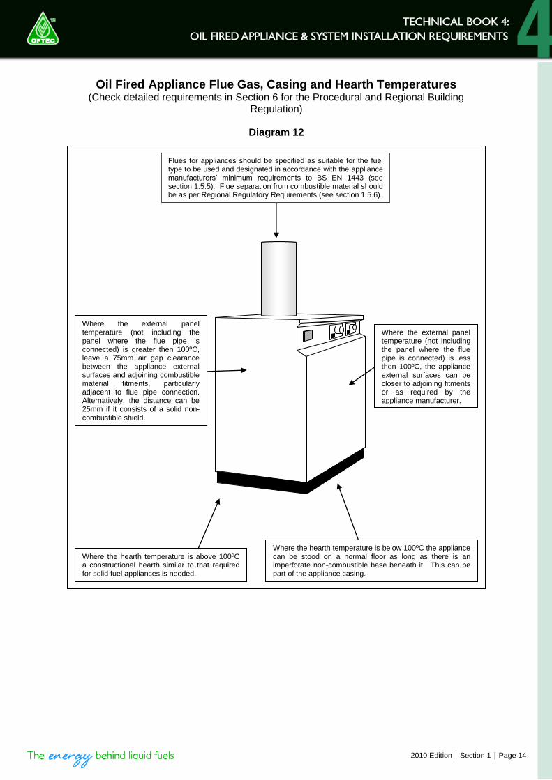
Oil Fired Appliance Flue Gas, Casing and Hearth Temperatures (Check detailed requirements in Section 6 for the Procedural and Regional Building
Regulation)
Diagram 12
Flues for appliances should be specified as suitable for the fuel type to be used and designated in accordance with the appliance manufacturers’ minimum requirements to BS EN 1443 (see section 1.5.5). Flue separation from combustible material should be as per Regional Regulatory Requirements (see section 1.5.6).
Where the external panel temperature (not including the panel where the flue pipe is connected) is less then 100ºC, the appliance external surfaces can be closer to adjoining fitments or as required by the appliance manufacturer.
Where the hearth temperature is below 100ºC the appliance can be stood on a normal floor as long as there is an imperforate non-combustible base beneath it. This can be part of the appliance casing.
Where the hearth temperature is above 100ºC a constructional hearth similar to that required for solid fuel appliances is needed.
Where the external panel temperature (not including the panel where the flue pipe is connected) is greater then 100ºC, leave a 75mm air gap clearance between the appliance external surfaces and adjoining combustible material fitments, particularly adjacent to flue pipe connection. Alternatively, the distance can be 25mm if it consists of a solid non-combustible shield.

Page 15 | Section 1 | 2010 Edition
1.2 Appliance Location
1.2.1 Heating System Requirements
When considering the location of an oil firing appliance, it is important to bear in mind the ease with which pipework for water circulation and oil supply can be run to it, the availability of an open flue, or the clearances needed around a balanced flue externally. For open flued appliances, a combustion air supply path will be required, and for all boilers in compartments ventilation air will be required. Condensing appliances will also require the routing of condensate disposal systems and the provision of maintenance access to condensate traps.
Unless a sealed circulation heating system is being used, an open safety vent pipe will have to be run from the boiler to the feed and expansion cistern, probably in the loft space above the level of the top of the system. The vent has to rise continuously from the boiler to the point where it turns over the feed cistern. This pipe, and its associated feed and expansion pipe, must not be run where freezing could take place. Information about heating system design and the location of open vents and feed pipes is given in the Domestic Heating Design Guide.
1.2.2 Hearth Temperature (Diagram 12)
Oil fired appliances having hearth temperatures not exceeding 100oC do not require purpose built constructional hearths if they stand on an imperforate rigid non-absorbent and non-combustible base. This can be part of the appliance itself.
1.2.3 Casing Temperature (Diagram 12)
Oil fired appliances having side and back panel temperatures not exceeding 100oC can be fitted without an air space being left between their casings and adjacent kitchen and other fittings. Nearly all boilers will have panel and hearth temperatures below this figure. Some cookers may have higher temperatures.
1.2.4 Bathroom/Shower Room and Bedroom/Bed-sitting Room Installations
Open flued oil fired appliances must not be installed in and/or draw their combustion and ventilation air from a bathroom or bedroom. When appliances are installed within a bathroom/shower room the electrical connections to the appliance should be safe, the appliance outer casing or compartment should enclose switches and controls so a person using the bath or shower cannot touch them. Electrical works should meet the requirements of BS 7671.
1.2.5 Under-stairs Installations
If no alternative location is available, the boiler can be located in an under-stairs space where the premises does not exceed two storeys. The boiler should be of the room sealed type and all internal surfaces around and above the boiler, including its base, should be non-combustible or lined with non-combustible material having a fire resistance of not less than 30 min. Where the area is enclosed, the enclosure must be a 30 min. fire compartment ventilated from the outside. A notice stating that the compartment is to be used for nothing but the boiler is to be placed on the door, which is to be of the self-closing type. Reference should be made to BS 5410: Part 1 before proceeding.
AMD 04-1214-33

2010 Edition | Section 1 | Page 16
1.2.6 Loft Installations
Only in exceptional circumstances, where there is no other possible installation location, a boiler can be located in the loft space. Reference must be made in all cases to BS 5410 : Part 1 and the house insurers and local Fire Authority should also be consulted.
1.2.7 Garage Installations
Garages are often used for the siting of oil-fired boilers, as they provide a means of siting the boiler outside the living area. Only room sealed boilers should be installed in garages to design out the risk of ignition of petrol vapours and the contamination of combustion air supplies from vehicle exhaust gases.
If there is a risk of the boiler being damaged by a vehicle, some protection must be provided. Room should also be left for servicing to take place at the front of the boiler or at other points as required by the appliance manufacturer.
If the garage is unheated frost protection should be provided, please see sub-section 3.16.3.
1.2.8 External Boiler Installations
Some oil-fired boilers can be installed externally or partly externally with their burners accessed from the outside. The main consideration to bear in mind with these installations is the safety of the installation (including electrical), commissioning and service technician who has to work on the boiler.
A boiler installed externally should be either:
a) specifically manufactured for external installation without additional protection; or b) installed in an enclosure capable of providing suitable weather protection.
When installing external boilers special attention should be made to the following points:
Adjacent buildings, structures, or overhanging foliage from trees, etc. which may cause stagnation and prevent dispersal of products of combustion.
The risk of down draught from prevailing winds hitting adjacent buildings or structures
Oil storage tanks should be at least 1.8m away from an appliance flue termination/point of discharge. This distance is measured from the appliance flue terminal, not the appliance itself.
The final direction of discharge from the flue terminal to avoid nuisance complaints from occupants and neighbouring properties.
Remote acting fire valve to be positioned external to the appliance casing.
Providing a weather protected fused double-pole switch to electrically isolation of the boiler.
Providing the system with protection against corrosion, damage and freezing.
Allowing safe access for maintenance.
Ensuring all electrical work is in accordance with BS 7671.
1.3 Fire Valve Positioning
1.3.1 Fire Valves
The fitment of a remote acting fire valve is an integral part of an appliance installation. For details surrounding fire valve positioning, please see OFTEC Technical Book 3, Section 2.
AMD 04-1214-33

Page 17 | Section 1 | 2010 Edition
1.4 Chimney Requirements and Performance
1.4.1 General
Every type of flue and chimney construction is required to comply with EC Regulations. BS EN 1443 is the general document for conventionally open flued systems. Flue and chimney products and systems are manufactured from many different materials and are formed with a significant variety of diameters and configurations. For that reason, there are a number of chimney constructions and applications manufactured specifically for use with open flued oil-fired appliances.
1.4.2 Chimney/Flue Definitions
Some confusion can exist in respect of the use of the terms ‘flue’ ‘and ‘chimney’. For oil fired appliances, the definitions shown in Diagrams 13a, 13b and 13c should apply. A flue is defined as the circular or rectangular “tube” through which flue gases pass from an appliance to the external atmosphere. The flue can be enclosed within a single skin construction, a double wall construction, insulated or otherwise and within masonry construction. The chimney is defined as the construction containing a flue. A flue pipe normally connects an appliance to a masonry or factory-made chimney, but can also be connected directly to an appliance and run up through a building directly to the outside. This latter arrangement should be very carefully considered, due to the relatively low flue gas temperatures generated by modern oil-fired appliances which can result in the creation of a less than effective average draught (see sub-section 1.4.4.). A single wall flue pipe exposed to cold temperatures in a roof space can result in excessive cooling of the flue gases, and in turn severely interfere with the draught. Chimneys of masonry construction are built with a clay liner and should be retrospectively fitted with a flexible stainless steel liner or an alternative material as specified by the appliance manufacturer. Lining chimneys can be a difficult operation. To prolong the life of a liner, it is essential that the inside of the masonry is thoroughly cleaned to remove all traces of any soot and debris. If the chimney is not straight, it is usually necessary to temporarily remove some bricks on the corners, to enable the liner to be positioned centrally. Whenever a new appliance is installed or replaced having reached the end of its useful life, a new flue liner should always be fitted.
2010 Edition | Section 1 | Page 28
NOTE: The diameter of such chimneys may be oversized and reference must always
be made to the appliance manufacturer’s installation instructions before connection is made. Where a reduced chimney diameter is necessary, a proprietary plastic or stainless steel chimney liner meeting the performance requirements of the appliance should be used.
Liners should be installed in accordance with their manufacturer’s instructions. Appropriate components should be selected to form the flue without cutting and to keep joints to a minimum. Bends and offsets should only be formed with matching factory made components. Liners need to be placed with the sockets or rebate ends uppermost to contain moisture and other condensates in the flue. Joints should be sealed with fire cement or refractory mortar and installed in accordance with the manufacturer’s instructions. Spaces between the lining and the surrounding masonry should not be filled with mortar. In the absence of liner manufacturer’s instructions, the space could be filled with a weak insulating concrete such as mixtures of:
a) One part sulphate resisting Portland cement to 20 parts suitable lightweight expanded clay aggregate, minimally wetted, or
b) One part sulphate resisting Portland cement to 6 parts vermiculite, or
c) One part sulphate resisting Portland cement to 10 parts Perlite.
1.5.4 In-situ Lining
One method of lining and insulating chimneys that is sometimes used is called ‘in-situ lining. In this, a lozenge shaped former is lowered down the chimney and then inflated to make the flueway opening. It must be carefully positioned centrally within the chimney, especially on bends. This will usually entail some structural work. Lightweight Insulating concrete is then pumped between the inflatable former and the chimney. When the concrete has set, the former is deflated and removed, leaving a smooth flueway. This process must only be undertaken by experienced skilled operators, who have third party accreditation for their procedures and materials. For further information contact the National Association of Chimney Engineers (NACE, www.nace.org.uk) Once installed it is very difficult to remove the material in the event of there being any problems with it.
1.5.5 Factory Made Insulated Chimneys
Regional Building Regulations state that factory-made insulated chimneys can be used for oil fired appliances. These must be assessed and comply with:
a) BS EN 1856: Parts 1 & 2, Chimneys. Requirements for Metal Chimneys, System Chimney Products and Metal Liners and Connecting Flue Pipes.
b) BS EN 1859: Chimneys. Metal Chimneys. Tests Methods.
And where the appliance is open flued, it should be applied in accordance with:
c) BS EN 12391: Part 1 Chimneys - Execution Standard for Metal Chimney, Part 1 Chimneys for Non-room Sealed Heating Appliances.
Such chimney products must be applied and installed to these requirements as well as the installation instructions supplied by both the appliance and the flue and chimney manufacturer.
AMD 04-1214-33
Page 29 | Section 1 | 2010 Edition
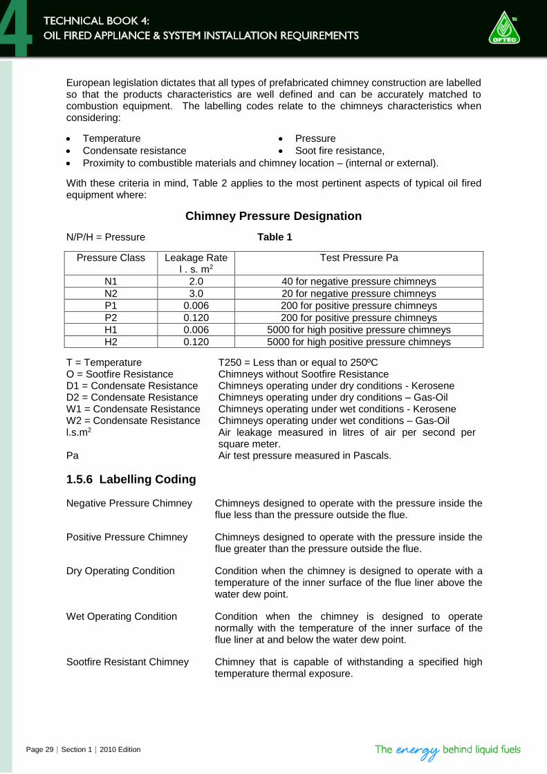
European legislation dictates that all types of prefabricated chimney construction are labelled so that the products characteristics are well defined and can be accurately matched to combustion equipment. The labelling codes relate to the chimneys characteristics when considering:
Temperature Pressure
Condensate resistance Soot fire resistance,
Proximity to combustible materials and chimney location – (internal or external).
With these criteria in mind, Table 2 applies to the most pertinent aspects of typical oil fired equipment where:
Chimney Pressure Designation
N/P/H = Pressure Table 1
Pressure Class Leakage Rate l . s. m2
Test Pressure Pa
N1 2.0 40 for negative pressure chimneys
N2 3.0 20 for negative pressure chimneys
P1 0.006 200 for positive pressure chimneys
P2 0.120 200 for positive pressure chimneys
H1 0.006 5000 for high positive pressure chimneys
H2 0.120 5000 for high positive pressure chimneys
T = Temperature T250 = Less than or equal to 250ºC O = Sootfire Resistance Chimneys without Sootfire Resistance D1 = Condensate Resistance Chimneys operating under dry conditions - Kerosene D2 = Condensate Resistance Chimneys operating under dry conditions – Gas-Oil W1 = Condensate Resistance Chimneys operating under wet conditions - Kerosene W2 = Condensate Resistance Chimneys operating under wet conditions – Gas-Oil l.s.m2 Air leakage measured in litres of air per second per
square meter. Pa Air test pressure measured in Pascals.
1.5.6 Labelling Coding
Negative Pressure Chimney Chimneys designed to operate with the pressure inside the flue less than the pressure outside the flue.
Positive Pressure Chimney Chimneys designed to operate with the pressure inside the flue greater than the pressure outside the flue.
Dry Operating Condition Condition when the chimney is designed to operate with a temperature of the inner surface of the flue liner above the water dew point.
Wet Operating Condition Condition when the chimney is designed to operate normally with the temperature of the inner surface of the flue liner at and below the water dew point.
Sootfire Resistant Chimney Chimney that is capable of withstanding a specified high temperature thermal exposure.

2010 Edition | Section 1 | Page 32
The Separation of Combustible Material from Factory Made Insulated Metal Chimneys meeting BS EN 1859
Diagram 17
Where a factory-made metal chimney penetrates a fire compartment wall or floor it must not breach the fire separation requirements as required by Regional Building Regulations, but the requirements may be met by: a) Using a factory-made metal chimney of the appropriate level of fire resistance, or b) Casing the chimney in non combustible material giving at least half the fire resistance
recommended for the fire compartment wall or floor.
Combustible Materials must be proven to be at a safe temperature when at a declared distance “X” from the outer chimney skin, in most cases not less than 50 mm.
Additional insulated materials MUST NOT be used with any floor or ceiling penetration arrangements.
The actual clearance criteria and design of the floor penetration components will be as submitted by individual chimney manufacturers. They will vary and will have demonstrated compliance with and be approved to BS EN 1859

Page 33 | Section 1 | 2010 Edition
1.5.7 Flue Pipe and Materials
Regional Building Regulations state that when the flue gas temperature of an appliance is less than 250oC, single and twin wall flue pipes similar to those used for gas appliances can be used. This is NOT applicable and does NOT take account of high efficiency condensing appliances. Care must be taken as flue pipes and materials deemed suitable for gas applications may not contain a stainless steel flue and can run the risk of corrosion. Flue pipe manufacturers produce individual kerosene specific gas type flues containing stainless steel liners for condensing and non-condensing appliances (see Table 2) for this purpose. Flue jointing for condensing appliances should include either “O” ring seals or suitable silicone jointing in place of the traditional use of fire cement. These can be run internally in a similar manner to those used for gas appliances The requirements for passing flue pipes through the structure of a building are summarised in Table 3. Single skinned flue pipes should not be run externally or in internal areas where severe chilling is likely. Single wall flue pipes with spigot and socket joints must be fitted with the sockets pointing upwards.
Safety Installation Requirements for Flue Pipes serving Oil Fired Boilers discharging Flue Gas Temperatures Below 250°C.
Table 4
Location Single wall flue pipe Double wall flue pipe
Where external surfaces of the flue pipe are adjacent to any combustible material.
Minimum 25mm separation.
Minimum 25mm separation measured from the inside of the flue/chimney (see note) wall.
Where a flue pipe passes through a cupboard, storage space, wall, floor, ceiling or partition.
The flue pipe should be separated from any combustible material by a non-combustible sleeve or shield providing a minimum 25mm air gap clearance.
Where a flue pipe passes through a space other than in the room where the appliance is located and where the surface of any part of the flue pipe can exceed 85oC
The flue pipe must be located/protected to prevent personal contact by room occupants.
External Installation Not recommended Insulated double wall system should be used.
Passage through a compartment of separate occupation, i.e., in flats or similar
Not permitted.
NOTE: Chimney is mentioned because some prefabricated metal chimneys may
have a wall thickness of 25mm, in which case the outer surface of the system could be safely used in contact with combustible materials. However, under such circumstances, a small clearance is still recommended, if only to enable access for maintenance and replacement. For appliances with flue gas temperatures above 250°C refer to appliance and flue manufacturer’s installation instructions.
AMD 04-1214-33

2010 Edition | Section 1 | Page 38
pitched roof, no cowl can overcome the problem. The problem should be investigated and the problem eliminated by a better designed termination. Often, just raising the height of the terminal location so that it is clear of a pressure zone is all that is needed. Note that some proprietary terminals may not be suitable for use with oil fired appliances, and checks may need to be made with the appliance manufacturer.
1.5.14 Discharge at Low Level
Flue terminals are permitted to be located less than 2.0 metres above ground level where they are purposely designed to do so and the fuel being used is Class C2 Kerosene. Only appliances tested for suitability for use in low level discharge mode should be used in these cases. For guidance on location and clearance requirements relating to low level open flue terminations, see diagram 20b and 20c. Additionally, appliance manufacturers' installation instructions should be studied as a manufacturer may require clearances exceeding those in diagram 20b, which would take preference over generic guidance.
Note: Under no circumstances should oil combustion appliances burning Class D Gas Oil terminate below 2.0m above ground level.
Note: All flue terminals located below 2.0m above ground level must be
protected by the use of a suitable terminal guard.
1.5.15 Requirements for Termination
Oil fired boiler flues should not be terminated beneath windows or where higher parts of the building will affect the pull of the flue or chimney. Appliance manufacturers' instructions must be referred to, as their requirements for safe operation may be more onerous.
1.5.16 Flue Gas Temperature (Regular Appliances (non-condensing))
A very important factor in flue performance is the temperature of the combustion gases in the flue. This is normally referred to as the flue gas temperature, or FGT. Temperature has always been important, but is now even more so, as appliance efficiencies have risen available flue gas temperatures have fallen. Although pressure jet burners impart a useful velocity to the combustion process, it is still necessary to ensure that flue gases leave the flue system reasonably warm, so as to ensure their easy dispersal. It is also very necessary to prevent their temperature falling below their acid dew point level to avoid condensation. Water is present as vapour in flue gases because of the high temperature of the combustion process. As cooling takes place the point will be reached when the vapour will condense back into its liquid form. At normal atmospheric pressure, water boils at 100oC, but water vapour actually has to drop down to about 60o before it condenses. This is not the same with acid vapours. As there is a minor sulphur content in the fuel, the liquid is mildly acidic. This will condense at a temperature of about 125oC, and cause problems for non-condensing appliances which are not designed for this eventuality. Flue routes where excessive heat loss is likely are those external to or partly external to buildings. Masonry flues of this type must be lined and insulation may well also be required to be inserted between the liner and the chimney. Single skin flue pipe must never be used
AMD 04-1214-33

Page 39 | Section 1 | 2010 Edition
externally. Indeed, when constructing external flues with modern heating appliances, anything other than a well insulated manufactured chimney is likely to cause problems. Current building insulation practices also result in much colder roof spaces, so thought needs to be given as to whether it is wise to run any single skin flue pipe through roof cavities. The best way to keep flue gases warm is to pass them through a well insulated vertical flue system. To preserve flue gas temperature, it is necessary to use flue materials and construction resistant to the passage of heat. One of the main means of achieving this is to use twin-walled flues, whereby the inner flue is kept warm by the air trapped between it and the outer flue. This only works if the air between the flue is completely sealed in place. A significant improvement in performance results from adding insulation between the outer and inner flues, and this type of construction is often necessary with modern high efficiency boilers. Having an oversized flue can be as harmful to efficient flue operation as having too little. Excessive flue space reduces the velocity of the gases in the chimney, and can reduce their temperature. More flue problems result from oversized chimneys than from undersized ones. Where a masonry chimney is already fitted with an oversized built-in clay lining, an additional liner of the correct size should be fitted inside the oversized one.
1.5.17 Condensing Appliance Flues
When choosing the location for a condensing boiler, special consideration must be given to the positioning of the flue terminal. Condensing boiler flue terminals should be sited so that the plume of wet products does not impinge on or significantly affect the use of the householder’s dwelling and any neighbouring buildings. A plume nuisance complaint can result in legal enforcement as a statutory nuisance. It should be noted that the normal statutory clearance required around low level flue terminals may not be sufficient to cope with plume dispersal from a condensing appliance. The following points should be considered:
Plumes can extend out horizontally and can also drift out to the sides and above the terminal. Care needs to be taken, therefore, to avoid plume reaching adjacent surfaces, particularly windows and neighbours dwellings.
Flue terminals need to be located where air can pass freely across them to disperse vapour.
The effect of the moisture generated must be considered in relation to the possible corrosion of metal parts it might reach and to the possible formation of ice on pathways in freezing conditions.
Keep flue terminals a minimum of 1m (horizontally) from openings in the building.
Do not install flue terminals directly below a window.
Do not install flue terminals next to a door.
Do not install flue terminal within 1m of ventilated soffits or eaves.
Keep flue terminals at least 2.5m away a surface or boundary facing the terminal.

2010 Edition | Section 1 | Page 44
1.7 Clearance
1.7.1 Regular Appliance (Open, Low Level Discharge and Balanced) Flue Termination Clearance
1.7
C
leara
nce
1.7
.1 R
eg
ula
r A
pp
lia
nc
e (
Op
en
, L
ow
Le
ve
l D
isc
ha
rge
an
d B
ala
nc
ed
) F
lue
Te
rmin
ati
on
Cle
ara
nce
The b
asic
requirem
ent w
ith r
egard
to f
lue p
ositi
onin
g is that
no h
azard
or
nuis
ance is c
aused b
y the flu
e g
ases. D
iagra
ms 2
0a a
nd 2
0b s
how
s
cle
ara
nces a
dvis
ed b
y B
S 5
410 P
art
1.
Regio
nal r
equirem
ents
where
flu
e c
leara
nces d
iffer
can b
e found in
the r
egio
nal r
equirem
ents
section in
this
book.
Cle
ara
nces a
dvis
ed
by B
S 5
410 P
art
1
D
iag
ram
20a
A G
E
B
C &
D
KF
F
L
NO
P
H
J
Bo
un
da
ry
Boun
da
ry
F
Q
Q
Q
Q
Q
R
AMD 04-1214-33

Page 45 | Section 1 | 2010 Edition
Min
imu
m d
ista
nces
to
term
inals
in
milli
metr
es a
s m
easu
red
fro
m t
he t
op
of
the c
him
ney o
r th
e o
ute
r ed
ge
of
wh
ere
flu
e g
ases e
xit
th
rou
gh
lo
w l
eve
l d
isch
arg
e o
pen
ing
s
Lo
cati
on
Ap
plian
ce B
urn
er
Typ
e
Pre
ss
ure
Jet
Va
po
ris
ing
No
n-C
on
den
sin
gC
on
den
sin
g
AD
irectly
belo
wan
openin
g,air
brick,openin
gw
indow
etc
.600
1000
Not allo
wed
BH
orizonta
llyto
an
openin
g,air
brick,openin
gw
indow
etc
.600
1000
Not allo
wed
CB
elo
wa
gutter,
eaves
or
balc
ony
with
pro
tection
75
1000
Not allo
wed
DB
elo
wa
gutter
or
abalc
ony
withoutpro
tection
600
1000
Not allo
wed
EF
rom
vert
icalsanitary
pip
ew
ork
300
-N
ot allo
wed
FF
rom
an
inte
rnalor
exte
rnalcorn
er
or
surf
ace
or
boundary
alo
ng
sid
eth
ete
rmin
al
300
-N
ot allo
wed
GA
bove
gro
und
or
balc
ony
level
300
-N
ot allo
wed
HF
rom
asurf
ace
or
aboundary
facin
gth
ete
rmin
al
600
2500
Not allo
wed
JF
rom
ate
rmin
alfa
cin
gth
ete
rmin
al
1200
-N
ot allo
wed
KV
ert
ically
from
ate
rmin
alon
the
sam
ew
all
1500
-N
ot allo
wed
LH
orizonta
llyfr
om
ate
rmin
alo
nth
esam
ew
all
750
-N
ot allo
wed
MA
bove
the
hig
hestpoin
tofan
inte
rsection
with
the
roof
600
-1000
NF
rom
avert
icalstr
uctu
reon
the
sid
eofth
ete
rmin
al
750
-2300
OA
bove
avert
icalstr
uctu
rele
ss
than
750m
mfr
om
the
sid
eofth
ete
rmin
al
600
-1000
PF
rom
aridg
ete
rmin
alt
oa
vert
icalstr
uctu
reon
the
roof
1500
-N
ot allo
wed
QA
bove
or
toth
esid
eofany
ope
nin
gon
afla
tor
slo
pin
gro
of
300
-300
RB
elo
wany
op
en
ing
on
aslo
pin
gro
of
1000
-1000
SE
E N
EX
T P
AG
E F
OR
IM
PO
RT
AN
T N
OT
ES
AMD 04-1214-33

2010 Edition | Section 1 | Page 46
NOTES: 1. Terminals should be positioned to avoid products of combustion accumulating in stagnant
pockets around the building, or entering into buildings.
2. Appliances burning Class D oil have additional restrictions (see sub-section 1.5.14)
3. Vertical structures in N, O and P include tank or lift rooms, parapets, dormers etc.
4. Terminating positions A to L are only permitted for appliances that have been approved for low level flue and low level balanced flue discharge when tested to BS EN 303-1.
5. Terminating positions must be at least 1.8m distant from an oil storage tank unless a wall with at least 30 minutes fire resistance and extending 300mm higher and wider than the oil storage tank is provided between the oil storage tank and the terminating position.
6. Where a flue is terminated less than 600mm away from a projection above it and the projection consists of plastic or has a combustible or painted surface, then a heat shield of at least 750mm wide should be fitted to protect these surfaces.
7. For terminals used with vaporising burners, a horizontal distance of at least 2300mm is required between the terminal and the roof line.
8. If the lowest part of the terminal is less than 2m above the ground, balcony, flat roof or other place to which any person has access, the terminal must be protected by a guard.
9. Notwithstanding the dimensions given in the diagram and table, a terminal should not be sited closer then 300mm to combustible material.
10. It is essential that a flue or chimney does not pass through the roof within the shaded area shown by dimensions Q and R.
11. Where protection is provided for plastic components, such as guttering, it is essential that this is to the standard specified by the manufacturer of the plastic components.
Separation Between a Boundary and Terminal at Right Angles
Diagram 20b
Pressure Jet
Appliance
300mm minimum
Boundary as Party wall
Plan at party wall
AMD 04-1214-33
Page 47 | Section 1 | 2010 Edition
1.7.2 Condensing Appliance Flue Termination Clearances
Diagrams 20a and 20b show clearances advised by BS 5410 Part 1. When selecting a location for a condensing flue terminal, caution should be exercised to ensure that the flue is terminating in an area that will allow flue gases to disperse efficiently, not to stagnate or be carried across windows or neighbouring properties. Installers should be aware that additional recommendations apply to flues serving condensing appliances to alleviate the effect of plume nuisance which can lead to neighbours formally lodging claims of statutory nuisance with their Local Authority. Claims of this nature are considered on merit and can result in both a time and financial burden to the installer/householder. Diagram 21 highlights areas in more detail where it is not recommended to terminate condensing appliance flues () and recommends locations to help alleviate any potential plume nuisance (). NOTE: To aid installers some boiler manufactures offer plume management kits,
which allows more versatile siting of terminals, reduces visual impact and generally overcomes most siting difficulties. Reference should be made to the equipment manufacturer regarding plume management kits available.
AMD 04-1214-33

2010 Edition | Section 1 | Page 48
Condensing Appliance Flue Termination Recommendations to address Plume Nuisance
Diagram 21
(a) Terminals must not be sited under car ports.
(b) Terminals at low level (terminals under 2.1m) have more restrictive recommendations and should not be positioned near public footways, frequently used access routes, car parking spaces less then 2.5m from the terminal or patio’s (hard surface area).
(c) Terminals should not be positioned under a roof window.
(d) Terminals should be positioned at least 1m from any side and top of a roof window.
(e) Terminals should be positioned at least 1m away from an opening and below a gutter, eaves or balcony,
(f) Wall terminals should be sited a minimum of 2.5m from any facing wall, fence, building or property boundary
NOTE: Locations (c) and (d) are applicable for both conventionally open flues and
vertical balanced flues.
1m
1m 1m
2.5m
1m
(a)
(b)
(c)
(d)
(e)
(f)
AMD 04-0910-01

Page 49 | Section 1 | 2010 Edition
1.8 Combustion and Ventilation Air Supply
1.8.1 British Standard Requirements
For open flued oil fired appliances, BS 5410: Part 1 requires that combustion air must be provided into the room containing the appliance through purpose made non-closable openings, having a total free area of 5.5cm2 per kW of the appliance maximum output rating (see Diagram 22b). This requirement does not apply if a room sealed balanced flue appliance is used (see Diagram 23). The minimum recommended combustion/make up air provision for a vaporising appliance is to fit a grille passing air directly from the outside into the area in which the appliance is fitted, a free area of at least 100cm2.
1.8.2 Air Provision
Air is required for three purposes: 1. To provide oxygen for the combustion process for open flued appliances. 2. To ventilate a compartment and disperse latent heat 3. To provide ‘make-up’ air for flue dilution, where a draught break or stabiliser is fitted, and to
satisfy the demands of any extract fan or device to prevent flue interference for conventionally open flued appliance.
For reasons of safety and appliance performance, combustion and ventilation air supply to oil fired appliances must comply with the appropriate Building Regulation requirements. Please refer to the Regional Requirements, Section 6. The combustion air supply to open flued appliances should normally be provided at low level into a room. However, siting of low level vents to avoid causing discomfort by creating a cold draught across the floor is an important consideration. Where more than two air grilles are fitted in series across an air supply path, the free area of each grille should be increased by at least 50% over that required for a corresponding single air grille (see Diagram 22a). If combustion air is supplied through an underfloor duct the grilles at each end should be positioned in the vertical plane to reduce the risk of blockage. Ducts should be sized so as to reduce resistance to air flow.
1.8.3 Safety Requirements
The provision of an adequate combustion and ventilation air supply is vital for the safe operation of a fuel burning appliance, as poor combustion can result in the formation of Carbon Monoxide gas, which human exposure to can cause brain damage or death.
AMD 04-1214-33

2010 Edition | Section 1 | Page 50
1.8.4 Air Supply Source Restrictions
Oil fired boilers must not draw combustion air from a bathroom, bedroom nor garage. Air must not be drawn from under floor spaces in areas where Radon gas accumulations occur.
1.8.5 Compartment Ventilation Requirements
A compartment is a room or space partitioned for the purpose of containing plant and equipment, or a room or space of insufficient volume to satisfactorily disperse the build up of latent heat around the plant and equipment contained therein. BS 5410 Part 1 requires that when an appliance, whether of the open or balanced flue type, is located in a confined space, air must be provided through purpose made non closable openings for ventilation purposes. This is in addition to any air required for combustion purposes. Where the air is taken from a heated space (i.e. from an internal space) purpose made openings, one at high level and one at low level, both having free areas of 11cm2 per kW of appliance maximum output rating, are required. Where air is taken from outside the building, purpose made openings, one at high and one at low level, both having free areas of 5.5cm2 per kW of appliance maximum output rating, are required. It should be noted that compartments need to be provided with ventilation, whether the boiler is of the open flued or room sealed type.
1.8.6 Draught Break Stabilisers
Where the heating appliance is fitted with a draught break or stabiliser, an addition of 5.5cm2 per kW of appliance maximum output rating should be added to the combustion air allowance. This is not required when compartment ventilation air is supplied as noted in sub-section 1.8.5 above (see sub-section 1.4.6).
1.8.7 Air Supply Interference and Extract Fans
If the space in which an open flued appliance is fitted has an extract ventilation fan, the supply of air to the space should be sufficient to enable the boiler to operate satisfactorily when the fan is running to extract air at its maximum setting and all the windows, doors and closable vents are shut. The maximum permissible rate of fan extract for a pressure jet burner is 40 litres per second and 20 litres per second for a vaporising burner (see sub-section 1.9).
1.8.8 Low Level Discharge Flues
Appliances with low level discharge flues which are not room sealed must be treated as open flued appliances for combustion and ventilation air supply purposes.
1.8.9 Vertical Balanced Compartment Flues
A vertical balanced flue compartment is designed to provide all the combustion and ventilation air required. No additional openings are therefore required.
AMD 04-1214-33

Page 51 | Section 1 | 2010 Edition
1.8.10 Garage Installations
For garage installations, only room sealed boilers should be used. Ventilation to appliances should never be drawn from a garage space. This is to provide a degree of isolation between any petrol fumes or exhaust gases that could accumulate and effect boiler combustion In single storey garages, vertical balanced flues provide a useful means of terminating flue gases.
Free Area of Grilles are cm2 per kW of Appliance Maximum Rated Output
Diagram 22a
Open Flued Appliance in a Room Ventilated in Series
Open Flued Appliance in a Compartment Ventilated in Series
5.5
Conventional Open Flue
8.25 11.0
Room Hall Compartment
16.5
5.5
Conventional Open Flue
8.25 8.25
Room Hall Room
AMD 04-0515-33

2010 Edition | Section 1 | Page 52
Free Area of Grilles are cm2 per kW of Appliance Maximum Rated Output
Diagram 22b
Open Flued Appliance in a Room
Open Flue Boiler in Compartment Compartment Ventilated from Room Compartment Ventilated from Outside
See Regional Requirement of Section 6 for a worked example.
11.0
16.5
11.0
5.5 5.5
AMD 04-1214-33
Conventional Open Flue Or Open Flue Low Level Discharge
5.5

Page 53 | Section 1 | 2010 Edition
Free Area of Grilles are cm2 per kW of Appliance Maximum Rated Output
Diagram 23
Balanced Flued Appliance in a Room
Balanced Flue Boiler in Compartment Compartment Ventilated from Room Compartment Ventilated from Outside
See Regional Requirement of Section 6 for a worked example.
11.0
11.0
5.5
5.5
AMD 04-1214-33
No air grilles required
2010 Edition | Section 1 | Page 54
1.9 Extract Fans
1.9.1 General
If an open flued oil fired appliance is fitted in an area where its performance could be affected by the operation of an extract fan, measures must be taken to ensure that the operation of the fan does not interfere with the operation of the appliance. A flue draught interference test, as described in sub-section 1.9.3 below, must be undertaken in all cases (see sub-section 1.8.7).
1.9.2 Ventilation Restrictions
Where the oil fired appliance has a vaporising burner, then the mechanical extract rate from the area in which it is installed must not exceed 20 litres/second. Please see Diagram 24.
Where the oil fired appliance has a pressure jet burner the mechanical extract rate from the area in which it is installed must not exceed 40 litres/second. Please see Diagram 25.
Extract hoods should not be installed directly over oil fired open flued vaporising range cookers.
1.9.3 Flue Draught Interference Test
To undertake a flue draught interference test when the appliance and the fan are in the same room, the doors and windows of the room must be closed. Any adjustable ventilation openings must also be closed.
Where the extract fan is located elsewhere in the building, external doors, windows and adjustable ventilation openings must be closed and the internal doors must be left open during the test. The extract fan should then be run at its maximum setting.
Where the fan has established its normal air flow pattern the oil fired appliance should be set in operation at maximum output. Flue draught condition readings should then be taken with and without the extract fan running. These should be observed to see that they are within the flue draught parameters set by the appliance manufacturer and that no difference is observed in the flue draught reading both with the fan switched on and off.
NOTE: It is recommended that this test should be undertaken by an OFTEC Registered Service and Commissioning Technician holding an OFT 101/102 qualification.
1.9.4 Other Causes of Air Supply Interference
It should be noted that fan-powered air movement through household appliances such as tumble dryers, which extract air to the outside, can have the same effect on combustion appliances as an extract fan fitted for ventilation purposes. The effect of heating appliances using other fuels should also be taken into account.
Appliances using fuels other than oil, and which are located in areas from which they could affect air flow in the area containing the oil fired appliance, must have air supply arrangements which comply with the requirements of the appropriate Regional Building Regulations for those fuels. Their effect upon air flow to the oil fired appliance must be taken into account. It must also be remembered that any other open flues within a property (such as large open fire chimney places) can have a similar air extract effect and can result in flue draught interference.
AMD 04-1214-33

Page 55 | Section 1 | 2010 Edition
1.9.5 Make up Air Supply to Extract Fans
Extract fans should be positioned as far away from open flues serving oil fired appliances as possible and should have a sufficient dedicated air supply directly from the outside to permit a satisfactory flue draught interference test to be undertaken. This air supply should be provided through a separate non-closable grille at high level and be of an adequate size to replace air removed by the extract fan. (see diagrams 24 and 25). It is preferable for air supply for an extract fan to be located where it can serve the fan without the air stream passing close to the oil fired appliance.

2010 Edition | Section 5 | Page 19
5.8 Work Notification England and Wales
5.8.1 General
Changes to the Building Regulations in England and Wales mean that since April 1st 2005, Local Authority Building Control must be notified of any oil fired appliance, oil storage and supply system installation works undertaken and self-certificated by OFTEC Registered Businesses and Technicians. Furthermore, building owners must receive a certificate of any works undertaken in their home/premises, and that they comply with the Building Regulations in force on the date the works were completed. OFTEC registered businesses can notify their works to OFTEC, and OFTEC will inform the relevant Local Authority and provide a compliance certificate to the householder on the businesses behalf. For work notification in other regions, refer to the Regional Requirements at the back of this book.
5.8.2 Work Notification
OFTEC’s Works Notification Scheme not only meets legal requirements, but is an added benefit that OFTEC Registered Technicians can offer their customers. The only other alternative means of compliance is to arrange a Local Authority Building Control Inspection for any works subject to Building Regulations, which can be costly and time consuming. OFTEC offer three means of notifying work. This can be done by, a) registering work online (see sub-section 5.8.3), b) using the Building Regulations Work Notification Fax form (see sub-section 5.8.4) or, c) by telephoning 0845 65 85 080 / 01473 626 298. Please see the OFTEC website www.oftec.org for the latest options of performing Work Notification.
5.8.3 How to Register your Works Online
When notifying your works via the internet you will need to log into the Registered Technician’s area of the OFTEC website (www.oftec.org). Use your password to access Work Notifications. You can then:
Add a new Work Notification.
View Notification history.
Change your password. To add a new Notification you will need to input the following:
Job completion date (once entered this cannot be amended).
The address where the works were carried out. For new build, OFTEC will require details of the relevant Local Authority).
At this point you can also add your own unique job reference number. Once you have entered the site details, you will see a summary screen, click on the Add Work Details button to add work activity details.
AMD 04-1214-33

Page 20 | Section 5 | 2010 Edition
To add the job details you will need to complete the following.
Tick the box next to the name of each technician that worked on the job.
Choose the work activity from the drop down list of notifiable jobs.
Select the quantity of the type of work.
Click save to save details of work and return to the summary screen. If you experience any problems during the online notification process simply return to the summary screen and mark the record as invalid. This will prevent the job being notified to Local Authority Building Control and there will not be a charge. Job details can be amended at any time up to the point where the Local Authority is notified. However, the date cannot be amended, so if this is incorrect mark the notification as invalid to prevent it being reported and start another record with the correct details.
5.8.4 How to Register your Works by Fax
An updated version of the Building Regulations Work Notification Fax is available from the OFTEC website (www.oftec.org) or can be obtained from OFTEC on 0845 65 85 080. Once you have a master copy, this can be photocopied as many times as needed. The Building Regulations Work Notification Fax is spilt up into sections (1-4) which consist of a series of boxes. You should only complete the sections which correspond with the works you have completed and for which you hold the relevant class of OFTEC Registration.
AMD 04-1214-33

2010 Edition | Section 5 | Page 21
Building Regulations Work Notification Fax
Diagram 70
1. Record your full business name as registered with OFTEC.
2. Record a telephone number where you can be contacted if a query with the Building Regulations Work Notification arises.
3. List the individual OFTEC registration numbers of the registered technicians that are employed by the Registered Business concerned (see number 4) and who undertook the notifiable work they are going to report.
4. Record your OFTEC Business Registration number (this begins with a “C”).
OFTEC Building Regulations Work Notification Fax
To submit Fax to 09055 689 003
Your Business Name
Telephone No.
OFTEC Technician No(s).
1
Yo
u
Tech. 1 Tech. 2 Tech. 3 Tech.4
OFTEC Business Registration No. C
Contact Name
Address where the work was carried out
Site
Ad
dre
ss
2
County
Town
Street
House No.
Customer Name
Post code in full
Telephone No.
New Build (tick for New Build and enter Local Authority below)
Local Authority -
2a
a
4
Installation completion date (dd/mm/yyyy) / /20 Your Own Job Ref No. (optional)
Oil w
ork
co
mp
leted
Oil Work (enter quantity alongside each work activity undertaken)
Qty
Install an oil storage tank
Install oil supply pipework
Installation of an oil-fired boiler
Install an unvented hot water storage vessel
Installation an oil-fired room heater stove or cooker
Install a non-masonry flue/chimney system
Install a flue liner
Install a hot water system without storage
Install a heating system
Install an extension to an existing heating system
4a
Qty
5I declare that the above works have been carried out in accordance with Regional Building Regulations as required.
Signature:
The cost of fax notification will be £5.00 plus VAT. (£1.00 by premium fax line plus £4.00).
For details of how to notify online for less please contact OFTEC Registration on Tel 0845 65 85 080
FORM R518 Issue 11 Sep. 2014
Ele
ctric
al w
ork
co
mp
leted
Additional Certificates
Compliance Certificates produced for oil, heating,
hot water and electrical work self-certified under
Schedule 3 of The Building Regulations 2010 are
automatically sent to the property where the work is
carried out.
If you require a duplicate certificate please call
OFTEC Registration Services on Tel 0845 65 85 080.
You will need your OFTEC Company number and
address/postcode of the property ready when
calling.
Print Name:Date:
Electrical Work
Electrical installation work can only be notified via OFTEC by a
Technician holding OFT 103 Full Scope Part P registration.
Technician Name ………………………………………
Reg. No. ……………………………………………...
Install a replacement consumer unit
Partial rewire
Circuit alteration or addition in a kitchen or special
location
Install one or more circuits
New full electrical Installation (new build)
Rewire of all circuits
3
Install an vented hot water storage vessel
4b
4c
Renewable Technology Work
Renewable technology installation work can only be notified via OFTEC by a
Technician holding OFT-501 or OFT-504 registration.
Technician Name ………………………………………
Reg. No. ……………………………………………...
Install an air source heat pump
Install a solar thermal system
Install a ground source heat pump
Install a water source heat pump
Qty
Re
new
ab
le w
ork
co
mp
leted
Green Deal
Some or all of work subject to a Green Deal Plan
None of work subject to a Green Deal Plan
Tick
1.
2.
3.
4.
5.
7.
9.
14.
15.
16.
17.
6.
8.
10. 13.
12.
11.
AMD 04-1213-33

Page 22 | Section 5 | 2010 Edition
5. Record a contact name of the person in your company responsible for the Building
Regulations Works Notification. 6. Record the postal address as listed with the Royal Mail where the works were carried
out. Please ensure you provide the postcode, a contact name and telephone number for the person responsible for the property.
If property is new build, tick box and record the name of the Local Authority concerned.
7. Compliance Certificates produced for oil, heating, hot water and electrical work self-
certified under Schedule 3 of The Building Regulations 2010 are automatically sent to the property where the work is carried out. Duplicate certificates can be sent electronically by signing into your company area at www.ofteconline.com.
8. The date when the works were fully completed. 9. If you have your own unique reference/invoice number for the works, you can enter it in
this section so notification is easily recognisable for you. This is optional. 10. Section 4 lists the oil work types. You are required to put the quantity (if any) next to
each item of work you have completed. E.g. If you have installed a new boiler and heating system, you are required to notify both the boiler and the system which can be done on the same submission.
10.1 Registered Technicians holding the OFT 105E qualification can notify the following
works:
Installation of an oil-fired boiler.
Installation an oil-fired room heater stove or cooker.
Install a non-masonry flue/chimney system.
Install a flue liner.
Install a hot water system without storage.
Install a vented hot water storage vessel.
Install a heating system.
Install an extension to an existing heating system.
10.2 Registered Technicians holding the OFT 600a qualification can notify the following works:
Install an oil storage tank.
Install oil supply pipework.
10.3 Registered Technicians holding the OFT 107 qualification can notify the following works:
Install an unvented hot water storage vessel. 11. Tick the appropriate box to indicate whether the work undertaken was subject to a Green
Deal Plan.
AMD 04-1213-33

2010 Edition | Section 5 | Page 23
12. If renewable technology installation work is to be notified, the name and registration
number of the appropriately qualified technician (i.e. holding OFT 501 “Solar Thermal Systems” registration or OFT 504 “Heat Pump Systems” registration) should be entered here.
13. Section 4b lists the renewable technology work types. You are required to put the
quantity (if any) next to each item of work you have completed.
13.1 Technicians holding the OFT 501 qualification can notify the following works via OFTEC:
Install a solar thermal system.
13.2 Technicians holding the OFT 504 qualification can notify the following works via OFTEC:
Install a ground source heat pump.
Install an air source heat pump.
Install a water source heat pump.
14. If electrical installation work is to be notified, the name and registration number of the appropriately qualified technician (i.e. holding OFT 103 “Full Scope Part P” registration) should be entered here.
15. Section 4c lists the electrical work types associated with oil fired equipment. You are
required to put the quantity (if any) next to each item of work you have completed.
15.1 Technicians holding the OFT 103 qualification can notify the following works via OFTEC:
Circuit alteration or addition in a kitchen or special location.
Install one or more circuits.
Install a replacement consumer unit.
Rewire of all circuits.
Partial rewire.
New full electrical Installation (new build). Reference should be made to the Regional requirements at the back of this book for further guidance on which electrical works do and do not require notification.
16. You need to sign the form to declare that the works you are notifying have been carried
out in accordance with Local Building Regulations. Without a signature, the notification will not be processed.
17. The completed form is to be faxed back to OFTEC on this number. Check before
sending that the form has been completed fully. This is a premium rate fax line. For current cost verification please visit the OFTEC website (www.oftec.org).
AMD 04-1214-33

Page 24 | Section 5 | 2010 Edition
5.9 Safe Electrical Isolation
5.9.1 Safe Electrical Isolation
The safe isolation of electrical supplies is vital and for reference the nine steps for the safe isolation of electrical supplies are noted below: Step 1 Select an approved voltage indicator with fused leads conforming to HSE
Guidance Note GS38 Step 2 Prove correct function of the voltage indicator on an approved proving unit or a
known supply Step 3 Locate means of isolation for installation or circuit to be worked on e.g. main
isolator fuse or circuit breaker Step 4 Check if the installation circuit or fixed equipment to be isolated is in service Step 5 Isolate the installation or circuit by switching off and withdrawing the fuse(s) Step 6 Place fuse(s) in a safe place under your sole control or lock off the isolator or
circuit breaker, placing the key in a safe place under your sole control Step 7 Using the voltage indicator verify that the installation circuit or fixed equipment is
dead:
Phase to Phase (3 phase equipment only) Phase (Live) to Neutral Phase (Live) to Earth Neutral to Earth
Step 8 Re-check correct function of voltage indicator on the proving unit or on a known
supply Step 9 Fit warning label to main isolator, circuit breaker or fixed equipment indicating
personnel are working on the circuit
AMD 04-0413-18
2010 Edition | Section 6 | Page 3
6.2.3 Competent Persons
The Building Act 1984 requires a person carrying out certain types of building works to work under a Building Notice or Building Regulations approval from Local Authority Building Control. On 1st April 2002 an amendment to Regulation 12 of the Building Regulations came into force. OFTEC Registered installation, commissioning and servicing and tank installation Technicians are empowered to self certificate their own works. This exempts them from the need to give such notice when carrying out new installation work, replacement works or making a major change to the system in areas covered by their class of OFTEC Registration.
6.2.4 Work Notification
Changes to the Building Regulations mean that since April 1st 2005, Local Authority Building Control (via OFTEC, see Section 5 for OFTEC Procedures) must be notified of any oil firing installation works undertaken and self-certificated by OFTEC Registered Technicians. Furthermore, building owners must receive a certificate of any works undertaken in their home/premises, and that they comply with the Building Regulations in force on the date the works were completed.
6.2.5 Minimum Provisions for New Systems in New and Existing Dwellings
For oil fired boilers installed on or after 1st October 2010
All regular oil fired boilers shall have SEDBUK efficiency of not less than 90% as rated by SEDBUK 2005 or 88% as rated by SEDBUK 2009 and be of the condensing type. Published at http://www.ncm-pcdb.org.uk/sap/index.jsp
All combination oil fired boilers shall have SEDBUK efficiency of not less than 86% as rated by either SEDBUK 2005 or 2009 and be of the condensing type. Published at http://www.ncm-pcdb.org.uk/sap/index.jsp
For range cooker boilers:
All oil fired range cooker boilers should have an efficiency in excess of 80% as declared at www.rangeefficiency.org.uk
NOTE: For minimum system controls refer to requirements below for new systems installed on or after 1st April 2014.
For oil fired boilers installed on or after 1st April 2014
All regular oil fired boilers shall have SEDBUK efficiency of not less than 88% as rated by SEDBUK 2009 and be of the condensing type. Published at http://www.ncm-pcdb.org.uk/sap/index.jsp
All combination oil fired boilers shall have SEDBUK efficiency of not less than 86% as rated by SEDBUK 2009 and be of the condensing type. Published at http://www.ncm-pcdb.org.uk/sap/index.jsp
For range cooker boilers:
All oil fired range cooker boilers should have an efficiency of not less than 80% as rated by SEDBUK 2009. Published at www.rangeefficiency.org.uk
AMD 04-1214-33

Page 4 | Section 6 | 2010 Edition
Appliance minimum SEDBUK efficiencies on new build properties form part of the SAP calculation process, it is therefore important that the appliance efficiency utilised (as specified by the builder, developer, architect or consultant) is matched to this requirement. No variation of this should take place without prior consultation and agreement of the specifier. Systems for space and domestic hot water are required to have:
Primary circuits of the fully pumped type with full boiler controls, interlock and zones. Where space heating is provided in dwellings with a floor area over 150m2, the system should be divided into a minimum of two heating zones each with independent time and temperature interlock. See sub-section 3.18.6.
Thermostatic radiator valves are to be fitted on all radiators except those located in rooms which incorporate a room thermostat.
An automatic bypass valve as required by the appliance manufacturer’s installation instructions.
Vented hot water cylinders complying with the heat loss and heat exchanger requirements of BS 1566.
Un-vented hot water storage systems complying with BS 7206 or be certified by the British Board of Agrément or equivalent approval.
Been thoroughly cleaned and flushed using an appropriate inhibitor.
Water treatment provided in hard water areas.
All appliances, systems and associated equipment fully commissioned in accordance with manufacturer’s instructions.
6.2.6 Minimum Provisions for Replacement Systems in Existing Dwellings
Installation before 1st April 2014 As defined for new systems installed on or after 1st October 2010.* * Where an individual component such as the boiler only is being replaced, thermostatic radiator valves can be omitted. However, best practice would be to fit them as part of the contract of works. On boiler replacement only, where it is impractical or uneconomical to install a condensing boiler the property may be assessed for exemption using an OFTEC CD/30 Form. Where the outcome of an assessment formally exempts the property from having a condensing boiler installed, and the replacement boiler is a regular boiler, it must have a minimum SEDBUK efficiency of 85%. If the replacement boiler is a combination boiler, it must have minimum SEDBUK efficiency of 82%.
AMD 04-0214-26

2010 Edition | Section 6 | Page 5
For oil fired boiler replacements not involving a fuel or energy switch:
The SEDBUK efficiency should not be worse than 2 percent lower than the SEDBUK efficiency of the appliance being replaced.
NOTE: If the efficiency of the system or appliance is not known, efficiency values can
be taken from Table 4a or 4b of SAP 2012. For appliance replacements involving a fuel or energy switch (e.g. the replacement of an LPG boiler with an oil boiler):
The seasonal efficiency (SEDBUK) of the proposed appliance should not be less than that as defined for boiler replacements not involving a fuel or energy switch.
The proposed appliance’s equivalent seasonal efficiency must be greater than the existing appliance’s seasonal efficiency (SEDBUK) minus maximum 2 percentage points maximum allowance.
Installation on or after 1st April 2014 As defined for new systems installed on or after 1st April 2014.* * Where an individual component such as the boiler only is being replaced, thermostatic radiator valves and fully pumped circulation can be omitted, but are considered best practice. Advice should be taken from the boiler manufacturer regarding boiler compatibility with gravity circulation. On boiler replacement only, where it is impractical or uneconomical to install a condensing boiler the property may be assessed for exemption using an OFTEC CD/30 Form. Where the outcome of an assessment formally exempts the property from having a condensing boiler installed, and the replacement boiler is a regular boiler, it must have a minimum SEDBUK 2009 efficiency of not less than 84%. If the replacement boiler is a combination boiler, it must have minimum SEDBUK 2009 efficiency of not less than 82%. For oil fired boiler replacements not involving a fuel or energy switch:
The SEDBUK efficiency should not be worse than 2 percent lower than the SEDBUK efficiency of the appliance being replaced.
NOTE: If the efficiency of the system or appliance is not known, efficiency values can
be taken from Table 4a or 4b of SAP 2012. For appliance replacements involving a fuel or energy switch (e.g. the replacement of an LPG boiler with an oil boiler):
The seasonal efficiency (SEDBUK) of the proposed appliance should not be less than that as defined for boiler replacements not involving a fuel or energy switch.
The proposed appliance’s equivalent seasonal efficiency must be greater than the existing appliance’s seasonal efficiency (SEDBUK) minus maximum 2 percentage points maximum allowance.
AMD 04-1214-33

Page 6 | Section 6 | 2010 Edition
6.2.7 Minimum Provisions for New Non-Domestic Systems in New Buildings
Installation on or after 1st October 2010 Where a single boiler is used to meet the heat demand, its Minimum Oil Boiler Seasonal Efficiency shall be 84%. All multiple-boiler system efficiencies shall be not less than 82% for any individual boiler and 84% for overall multi-boiler system. Minimum controls package for new boiler and multiple-boiler systems are as follows:
Boiler Plant Output Package Minimum Controls
Less than 100kW A
a. Timing and temperature demand control, which should be zone specific where the building floor area is greater than 150m2.
b. Weather compensation except where a constant temperature supply is required.
100kW to 500kW B
a. Controls package A above; and b. Optimised start/stop control with either night set-back
or frost protection outside occupied periods; and c. Two stage high/low firing facility in boiler, or multiple
boilers with sequence control to provide efficient part-load performance.
Greater than 500kW (Individual Boilers)
C a. Controls package A and Controls package B; and b. For multi-stage oil-fired boilers, fully modulating
burner controls.
6.2.8 Minimum Provisions for Replacement Non-Domestic Systems in Existing Buildings
Installation on or after 1st October 2010 This requires that a minimum Effective Boiler Seasonal Efficiency as well as a minimum Boiler Seasonal Efficiency is met. As it may not always be possible or practicable to replace a standard efficiency non-domestic appliance with a high efficiency (condensing) appliance in an existing non-domestic building it is possible to utilise additional efficiency measures (over the minimum time, temperature, demand and zoning control requirements) to achieve Heating Efficiency Credits (% points) to achieve compliance with the minimum Effective Boiler Seasonal Efficiency as follows:
Minimum Effective Boiler Seasonal Efficiency (EBSE) for Oil = 86%
Minimum Oil Boiler Seasonal Efficiency = 84%
AMD 04-0214-26

2010 Edition | Section 6 | Page 13
6.3.3 Competent Persons
The Building Act 1984 requires a person carrying out certain types of building works to work under a Building Notice or Building Regulations approval from Local Authority Building Control. On 1st April 2002 an amendment to Regulation 12 of the Building Regulations came into force. OFTEC Registered installation, commissioning and servicing and tank installation Technicians are empowered to self certificate their own works. This exempts them from the need to give such notice when carrying out new installation work, replacement works or making a major change to the system in areas covered by their class of OFTEC Registration.
6.3.4 Work Notification
Changes to the Building Regulations mean that since April 1st 2005, Local Authority Building Control (via OFTEC, see Section 5 for OFTEC Procedures) must be notified of any oil firing installation works undertaken and self-certificated by OFTEC Registered Technicians. Furthermore, building owners must receive a certificate of any works undertaken in their home/premises, and that they comply with the Building Regulations in force on the date the works were completed.
6.3.5 Minimum Provisions for New Systems in New and Existing Dwellings
For oil fired boilers installed on or after 1st October 2010
All regular oil fired boilers shall have SEDBUK efficiency of not less than 90% as rated by SEDBUK 2005 or 88% as rated by SEDBUK 2009 and be of the condensing type. Published at http://www.ncm-pcdb.org.uk/sap/index.jsp
All combination oil fired boilers shall have SEDBUK efficiency of not less than 86% as rated by either SEDBUK 2005 or 2009 and be of the condensing type. Published at http://www.ncm-pcdb.org.uk/sap/index.jsp
For range cooker boilers:
All oil fired range cooker boilers should have an efficiency in excess of 80% as declared at www.rangeefficiency.org.uk
NOTE: For minimum system controls refer to requirements below for new systems installed on or after 1st April 2014.
For oil fired boilers installed on or after 1st April 2014
All regular oil fired boilers shall have SEDBUK efficiency of not less than 88% as rated by SEDBUK 2009 and be of the condensing type. Published at http://www.ncm-pcdb.org.uk/sap/index.jsp
All combination oil fired boilers shall have SEDBUK efficiency of not less than 86% as rated by SEDBUK 2009 and be of the condensing type. Published at http://www.ncm-pcdb.org.uk/sap/index.jsp
For range cooker boilers:
All oil fired range cooker boilers should have an efficiency of not less than 80% as rated by SEDBUK 2009. Published at www.rangeefficiency.org.uk
AMD 04-1214-33

Page 14 | Section 6 | 2010 Edition
Appliance minimum SEDBUK efficiencies on new build properties form part of the SAP calculation process, it is therefore important that the appliance efficiency utilised (as specified by the builder, developer, architect or consultant) is matched to this requirement. No variation of this should take place without prior consultation and agreement of the specifier. Systems for space and domestic hot water are required to have:
Primary circuits of the fully pumped type with full boiler controls, interlock and zones. Where space heating is provided in dwellings with a floor area over 150m2, the system should be divided into a minimum of two heating zones each with independent time and temperature interlock. See sub-section 3.18.6.
Thermostatic radiator valves are to be fitted on all radiators except those located in rooms which incorporate a room thermostat.
An automatic bypass valve as required by the appliance manufacturer’s installation instructions.
Vented hot water cylinders complying with the heat loss and heat exchanger requirements of BS 1566.
Un-vented hot water storage systems complying with BS 7206 or be certified by the British Board of Agrément or equivalent approval.
Been thoroughly cleaned and flushed using an appropriate inhibitor.
Water treatment provided in hard water areas.
All appliances, systems and associated equipment fully commissioned in accordance with manufacturer’s instructions.
6.3.6 Minimum Provisions for Replacement Systems in Existing Dwellings
Installation before 1st April 2014 As defined for new systems installed on or after 1st October 2010.* * Where an individual component such as the boiler only is being replaced, thermostatic radiator valves can be omitted. However, best practice would be to fit them as part of the contract of works. On boiler replacement only, where it is impractical or uneconomical to install a condensing boiler the property may be assessed for exemption using an OFTEC CD/30 Form. Where the outcome of an assessment formally exempts the property from having a condensing boiler installed, and the replacement boiler is a regular boiler, it must have a minimum SEDBUK efficiency of 85%. If the replacement boiler is a combination boiler, it must have minimum SEDBUK efficiency of 82%.
AMD 04-0214-27

2010 Edition | Section 6 | Page 15
For oil fired boiler replacements not involving a fuel or energy switch:
The SEDBUK efficiency should not be worse than 2 percent lower than the SEDBUK efficiency of the appliance being replaced.
NOTE: If the efficiency of the system or appliance is not known, efficiency values can
be taken from Table 4a or 4b of SAP 2012. For appliance replacements involving a fuel or energy switch (e.g. the replacement of an LPG boiler with an oil boiler):
The seasonal efficiency (SEDBUK) of the proposed appliance should not be less than that as defined for boiler replacements not involving a fuel or energy switch.
The proposed appliance’s equivalent seasonal efficiency must be greater than the existing appliance’s seasonal efficiency (SEDBUK) minus maximum 2 percentage points maximum allowance.
Installation on or after 1st April 2014 As defined for new systems installed on or after 1st April 2014.* * Where an individual component such as the boiler only is being replaced, thermostatic radiator valves and fully pumped circulation can be omitted, but are considered best practice. Advice should be taken from the boiler manufacturer regarding boiler compatibility with gravity circulation. On boiler replacement only, where it is impractical or uneconomical to install a condensing boiler the property may be assessed for exemption using an OFTEC CD/30 Form. Where the outcome of an assessment formally exempts the property from having a condensing boiler installed, and the replacement boiler is a regular boiler, it must have a minimum SEDBUK 2009 efficiency of not less than 84%. If the replacement boiler is a combination boiler, it must have minimum SEDBUK 2009 efficiency of not less than 82%. For oil fired boiler replacements not involving a fuel or energy switch:
The SEDBUK efficiency should not be worse than 2 percent lower than the SEDBUK efficiency of the appliance being replaced.
NOTE: If the efficiency of the system or appliance is not known, efficiency values can
be taken from Table 4a or 4b of SAP 2012. For appliance replacements involving a fuel or energy switch (e.g. the replacement of an LPG boiler with an oil boiler):
The seasonal efficiency (SEDBUK) of the proposed appliance should not be less than that as defined for boiler replacements not involving a fuel or energy switch.
The proposed appliance’s equivalent seasonal efficiency must be greater than the existing appliance’s seasonal efficiency (SEDBUK) minus maximum 2 percentage points maximum allowance.
AMD 04-1214-33

Page 16 | Section 6 | 2010 Edition
6.3.7 Minimum Provisions for New Non-Domestic Systems in New Buildings
Installation on or after 1st October 2010 Where a single boiler is used to meet the heat demand, its Minimum Oil Boiler Seasonal Efficiency shall be 84%. All multiple-boiler system efficiencies shall be not less than 82% for any individual boiler and 84% for overall multi-boiler system. Minimum controls package for new boiler and multiple-boiler systems are as follows:
Boiler Plant Output Package Minimum Controls
Less than 100kW A
a. Timing and temperature demand control, which should be zone specific where the building floor area is greater than 150m2.
b. Weather compensation except where a constant temperature supply is required.
100kW to 500kW B
a. Controls package A above; and b. Optimised start/stop control with either night set-back
or frost protection outside occupied periods; and c. Two stage high/low firing facility in boiler, or multiple
boilers with sequence control to provide efficient part-load performance.
Greater than 500kW (Individual Boilers)
C a. Controls package A and Controls package B; and b. For multi-stage oil-fired boilers, fully modulating
burner controls.
6.3.8 Minimum Provisions for Replacement Non-Domestic Systems in Existing Buildings
Installation on or after 1st October 2010 This requires that a minimum Effective Boiler Seasonal Efficiency as well as a minimum Boiler Seasonal Efficiency is met. As it may not always be possible or practicable to replace a standard efficiency non-domestic appliance with a high efficiency (condensing) appliance in an existing non-domestic building it is possible to utilise additional efficiency measures (over the minimum time, temperature, demand and zoning control requirements) to achieve Heating Efficiency Credits (% points) to achieve compliance with the minimum Effective Boiler Seasonal Efficiency as follows:
Minimum Effective Boiler Seasonal Efficiency (EBSE) for Oil = 86%
Minimum Oil Boiler Seasonal Efficiency = 84%
AMD 04-0214-27

2010 Edition | Section 6 | Page 23
6.4.4 Where a Building Warrant is required:
The following works will require a Building Warrant when carried out within a house with 3 or more storeys or a flat:
The installation of a new or replacement oil fired appliance with an output greater than 45kW.
The installation or alteration to a chimney or flue pipe (excluding any work associated with installing a flue liner).
The construction of a hearth not affecting the floor or wall structure.
The installation of an oil storage tank (with a capacity greater than 90 litres) including pipework connecting the tank to the combustion appliance.
The installation of a new unvented hot water cylinder (more than 15 litres capacity).
Any electrical installation or circuit where the voltage exceeds 50AC, 120DC. For non-residential buildings with public access (this includes assembly and entertainment buildings) with a storey or creating a storey not more than 7.5m high or any other non-domestic buildings a Building Warrant will be required for the same works as domestic buildings (above). NOTE: There may be some circumstances when an aspect of work is being
performed that generally does not require a Building Warrant, but will require a building warrant if that aspect of work is being performed as a part of other building works e.g. a full restoration project. Further information regarding building warrants should be obtained from the Local Authority responsible for the geographical area where the works are to be carried out.
6.4.5 Minimum Provisions for New Systems in New and Existing Dwellings:
For oil fired boilers installed on or after 1st October 2010
All regular oil fired boilers shall have SEDBUK efficiency of not less than 90% as rated by SEDBUK 2005 or 88% as rated by SEDBUK 2009 and be of the condensing type. Published at http://www.ncm-pcdb.org.uk/sap/index.jsp
All combination oil fired boilers shall have SEDBUK efficiency of not less than 86% as rated by either SEDBUK 2005 or 2009 and be of the condensing type. Published at http://www.ncm-pcdb.org.uk/sap/index.jsp
For range cooker boilers:
All oil fired range cooker boilers shall have a SAP seasonal efficiency in excess of 80% as declared at www.rangeefficiency.org.uk
NOTE: For minimum system controls refer to requirements below for new systems
installed on or after 1st April 2014.
AMD 04-1214-33

Page 24 | Section 6 | 2010 Edition
For oil fired boilers installed on or after 1st April 2014
All regular oil fired boilers shall have SEDBUK efficiency of not less than 88% as rated by SEDBUK 2009 and be of the condensing type. Published at http://www.ncm-pcdb.org.uk/sap/index.jsp
All combination oil fired boilers shall have SEDBUK efficiency of not less than 86% as rated by SEDBUK 2009 and be of the condensing type. Published at http://www.ncm-pcdb.org.uk/sap/index.jsp
For range cooker boilers:
All oil fired range cooker boilers should have an efficiency of not less than 80% as rated by SEDBUK 2009. Published at www.rangeefficiency.org.uk
Appliance minimum SEDBUK efficiencies on new build properties form part of the CO2 emissions calculation process which is integral to standard 6.1, it is therefore important that the appliance efficiency utilised (as specified by the builder, developer, architect or consultant) is matched to this requirement. No variation to this should take place without prior consultation and agreement of the specifier.
Systems for space and domestic hot water are required to have:
Primary circuits of the fully pumped type with full boiler controls, interlock and zones. Where space heating is provided in dwellings with a floor area over 150m2, the system should be divided into a minimum of two heating zones each with independent time and temperature interlock. See sub-section 3.18.6.
Thermostatic radiator valves are to be fitted on all radiators except those located in rooms which incorporate a room thermostat.
An automatic bypass valve as required by the boiler manufacturer.
Vented copper hot water storage vessels associated with the system should meet the heat loss and heat exchanger requirements in BS 1566: Part 1 2002
Un-vented hot water storage systems complying with BS 7206: 1990 or be the subject of approval by a notified body to an equivalent level of safety and performance.
All appliances, systems and associated equipment fully commissioned in accordance with the manufacturer’s instructions.
Occupiers of the building to be provided with information regarding maintenance and energy efficient use of equipment.
6.4.6 Minimum Provisions for Replacement Systems in Existing Dwellings
Installation before 1st April 2014
As defined for new systems installed on or after 1st October 2010.*
* Where an individual component such as the boiler only is being replaced, thermostatic radiator valves can be omitted. However, best practice would be to fit them as part of the contract of works.
AMD 04-1214-33

2010 Edition | Section 6 | Page 33
6.6.4 Minimum Provision for New/Replacement Systems in Existing Dwellings (Maximum heating zone 100m2)
All oil fired boilers installed on or after 1st April 2008 shall have a minimum seasonal HARP efficiency of 86% (www.sei.ie/harp). The system should be fully pumped and provided with full boiler controls, interlocks, zones and a cylinder thermostat, as well as independent time controls for the central heating and domestic hot water. The system should also be commissioned so that on completion the system and its controls are left in the intended working order and operate efficiently.
6.6.5 Appliance Installation
It is not permitted to install open flue appliances in domestic garages, therefore only room sealed balanced flue appliances should be installed in a garage location. Also, for oil burning appliances with a rated output up to 45kW, Building Regulations Technical Guidance Document J 2014, effective from 1st September 2014, requires:
Chimneys and flue-pipes connected to condensing pressure jet appliances burning class C2 fuel oil (kerosene) to have a minimum designation of T160 N2 W1 O.
Any room or space containing an appliance (other than a room sealed appliance) to have a permanent ventilation opening with a free area of at least: - 550mm2 per kW of rated output but in no case less than 6500mm2 where the air
permeability is greater than 5.0m3/(h.m2); or, - 6500mm2 + 550mm2 per kW of rated output above 5kW where the air permeability is
less than 5.0m3/(h.m2) (i.e. in dwellings built from 2008 onwards).
6.6.6 Carbon Monoxide Detection
From 1st September 2014, a carbon monoxide alarm (performing to IS EN 50291-1) must be fitted in the same room as any new or replacement open-flued combustion appliance installation, which is located within a dwelling and not designed solely for cooking purposes. Alarms must also be fitted in each bedroom (or within 5m of the bedroom door, measured along the path of the corridor) and in habitable rooms through which a flue passes. The alarms themselves must provide a visual and audible warning at the end of their working life.
Alarms should be positioned between 1m and 3m horizontally from the appliance. If they are located on the ceiling they should be at least 300mm from any wall. Alternatively, if they are located on a wall, they should be as high up as possible (above the height of any doors or windows) but not within 150mm of the ceiling. Alarms located in bedrooms should be located relatively close to the breathing zone of the occupants. Where a single room serves a living accommodation, then the alarm should be positioned as far from cooking appliances as possible but near to where the person sleeps. Further guidance on the installation of carbon monoxide detectors should be sourced from IS EN 50292 and from manufacturers’ instructions.
6.6.7 Electrical Works
It is recommended that all electrical works are carried out to BS 7671.
6.6.8 Contact Details
To report a pollution incident contact the Local Authority for that area
The Department of the Environment, Heritage and Local Government www.environ.ie
AMD 04-0814-31

Page 34 | Section 6 | 2010 Edition
6.7 Jersey
6.7.1 The Jersey Building Byelaws 1997
The Planning and Building Services are responsible for the Jersey Building Byelaws. The Jersey Building Byelaws are designed to ensure that buildings are safe, healthy places in which people can live and work. The Byelaws are compiled from various Technical Guidance Documents. The list below shows the different Technical Guidance Documents available: Technical Guidance Part 1 Structure Technical Guidance Part 2 Fire Safety Technical Guidance Part 3 Combustion Appliances Technical Guidance Part 4 Site Preparation and Resistance to Moisture Technical Guidance Part 5 Ventilation Technical Guidance Part 6 Drainage, Hygiene and Water Storage Technical Guidance Part 7 Stairs, Ramps and Protective Barriers Technical Guidance Part 8 Access and Facilities for Disabled People Technical Guidance Part 9 Resistance to Transmission of Sound Technical Guidance Part 10 Glazing Technical Guidance Part 11 Conservation of Fuel and Power Technical Guidance Part 12 Electrical Safety Technical Guidance Documents can be downloaded from www.gov.je
6.7.2 Work Notification
Changes to the Building Regulations mean that from July 1st 2007, Local Authority Building Control (via OFTEC, see Section 5 for OFTEC Procedures) must be notified of any oil firing installation works undertaken and self-certificated by OFTEC Registered Technicians. Furthermore, building owners must receive a certificate for any works undertaken in their home/premises, and that they comply with the Building Regulations in force on the date that the works were completed.
6.7.3 Minimum Provision for New Systems in New and Existing Dwellings:
For oil fired boilers installed prior to 1st January 2011
Oil Combination Boilers Minimum SEDBUK efficiency 82%
Oil (all other types of boilers) Minimum SEDBUK efficiency 85% Replacement boiler systems should be upgraded to fully pumped with full boiler controls interlock and zones (TRV’s to bedrooms). Where it is not practicable to upgrade an existing system to fully pumped (Good Practice Guide 302) full boiler controls interlock and zoning is required to be added to the existing system.
AMD 04-1214-33

2010 Edition | Section 6 | Page 35
For oil fired boilers installed on or after 1st January 2011
All conventional oil fired boilers shall have SEDBUK efficiency of not less than 90% as rated by SEDBUK 2005 or 88% as rated by SEDBUK 2009 and be of the condensing type. Published at http://www.ncm-pcdb.org.uk/sap/index.jsp
All combination oil fired boilers shall have SEDBUK efficiency of not less than 86% as rated by either SEDBUK 2005 or 2009 and be of the condensing type. Published at http://www.ncm-pcdb.org.uk/sap/index.jsp
For range cooker boilers:
All oil fired range cooker boilers should have an efficiency in excess of 80% as declared at www.rangeefficiency.org.uk
Appliance minimum SEDBUK efficiencies on new build properties form part of the SAP calculation process, it is therefore important that the appliance efficiency utilised (as specified by the builder, developer, architect or consultant) is matched to this requirement. No variation of this should take place without prior consultation and agreement of the specifier. General Systems for space and domestic hot water are required to have:
Primary circuits of the fully pumped type with full boiler controls, interlock and zones. Where space heating is provided, the system should be divided into a minimum of two heating zones each with independent temperature interlock. See sub-section 3.18.6.
Thermostatic radiator valves are to be fitted on all radiators except those located in bathrooms and rooms which incorporate a room thermostat.
An automatic bypass valve as required by the appliance manufacturer’s installation instructions.
Vented hot water cylinders complying with the heat loss and heat exchanger requirements of BS 1566.
Un-vented hot water storage systems complying with BS 7206 or be certified by the British Board of Agrément or equivalent approval.
Been thoroughly cleaned and flushed using an appropriate inhibitor.
Water treatment provided in hard water areas.
All appliances, systems and associated equipment fully commissioned in accordance with manufacturer’s instructions.
AMD 04-1214-33

Page 36 | Section 6 | 2010 Edition
6.7.4 Minimum Provision for Replacement Systems in Existing Dwellings
As defined for new systems.* * Where an individual component such as the boiler only is being replaced, thermostatic radiator valves can be omitted. However, best practice would be to fit them as part of the contract of works. Where it is impractical or uneconomical to install a condensing boiler the property may be assessed for exemption using an OFTEC CD/30 Form. Where the outcome of an assessment formally exempts the property from having a condensing boiler installed, and the replacement boiler is a regular boiler, it must have a minimum SEDBUK efficiency of 85%. If the replacement boiler is a combination boiler, it must have minimum SEDBUK efficiency of 82%.
6.7.5 Minimum Provision for New Non-Domestic Systems in New Buildings
Installation on or after 1st January 2011 A minimum Effective Boiler Seasonal Efficiency as well as a minimum Boiler Seasonal Efficiency is required for oil fired boilers:
Minimum Oil Boiler Seasonal Efficiency = 82% for any individual boiler
Minimum Oil Boiler Seasonal Efficiency = 84% for the overall multi-boiler system
6.7.6 Minimum Provision for Replacement Non-Domestic Systems in Existing Buildings
Installation on or after 1st January 2011 This requires that a minimum Effective Boiler Seasonal Efficiency as well as a minimum Boiler Seasonal Efficiency is met. As it may not always be possible or practicable to replace a standard efficiency non-domestic appliance with a high efficiency (condensing) appliance in an existing non-domestic building it is possible to utilise additional efficiency measures (over the minimum time, temperature, demand and zoning control requirements) to achieve Heating Efficiency Credits (% points) to achieve compliance with the minimum Effective Boiler Seasonal Efficiency as follows:
Minimum Effective Boiler Seasonal Efficiency (EBSE) for Oil = 86%
Minimum Oil Boiler Seasonal Efficiency = 84% Therefore if a boiler with a BSE of 84% was proposed to be used a minimum of two additional percentage points of Efficiency Credits would be required to meet the minimum figure of 86%. A boiler with a Seasonal Efficiency of 84% could be installed with:
Thermostatic Radiator Valves throughout = 1 Credit
Weather (internal/external temperature) compensation system = 1.5 Credits
AMD 04-1210-05
2010 Edition | Section 6 | Page 37
When totalled the Effective Boiler Seasonal Efficiency = 84 + 1 + 1.5 = 86.5% (exceeds minimum EBSE of 86%). OR For example the 84% BSE appliance installed in conjunction with the following:
Optimised Start/Stop controls = 2 Credits; would also achieve the minimum EBSE figure of 86%.
For further information regarding the minimum time, temperature, demand and zoning control requirements, please refer to OFTEC Information Sheet, Approved Document L2a and L2b (England and Wales) which is available on the OFTEC website www.oftec.org
6.7.7 Electrical Works
The Building Regulations in Jersey require that all electrical works are carried out to BS 7671.
6.7.8 Contact Details
To report a pollution incident contact the Pollution Hotline 01534 709535 States of Jersey Government website www.gov.je
AMD 04-1210-05

Page 38 | Section 6 | 2010 Edition
6.8 Guernsey
6.8.1 Guernsey Approved Documents
Part A Structure Part B Fire Safety Part C Site Preparation and Resistance to Moisture Part D Toxic Substances Part E Resistance to Passage of Sound Part F Ventilation Part G Health and Hygiene Standards Part H Drainage and Waste Disposal Part J Combustion Appliances and Oil Tanks Part K Safe Means of Access and Egress Part L Conservation of Fuel and Power Part M Access and Facilities for Disabled People Part N Glazing Part P Estate Roads and Service Roads
6.8.2 Control of Building Work
Regulation 6 Requirements Relating to Building Work Regulation 11 Materials and Workmanship Hazardous Waste – States of Guernsey Environment Department
6.8.3 Work Notification
Changes to the Guernsey Building Regulations mean that from April 1st 2007, Local Authority Building Control (via OFTEC, see Section 5 for OFTEC Procedures) must be notified of any oil firing installation works undertaken and self-certificated by OFTEC Registered Technicians. Furthermore, building owners must receive a certificate of any works undertaken in their home/premises, and that they comply with the Building Regulations in force on the date the works were completed.
6.8.4 Minimum Provision for New Systems in New Dwellings
Where appliance minimum SEDBUK efficiencies on new build properties are stated in the new build specification the appliance efficiency utilised (as specified by the builder, developer, architect or consultant) is matched to this requirement. No variation to this should take place without prior consultation and agreement of the specifier. New build energy conservation includes the requirement to provide fully pumped systems with dedicated time and temperature control along with full boiler interlock and zoning.
AMD 04-1214-33