Embed Size (px)
Citation preview
energies
Article
Design of Partial Discharge Test Environment forOil-Filled Submarine Cable Terminals andUltrasonic Monitoring
Yulong Wang 1,2, Xiaohong Zhang 1,*, Lili Li 1,2, Jinyang Du 1 and Junguo Gao 1
1 Key Laboratory of Engineering Dielectrics and its Application, Ministry of Education, Harbin University ofScience and Technology, Harbin 150080, China; [email protected] (Y.W.); [email protected] (L.L.);[email protected] (J.D.); [email protected] (J.G.)
2 College of Rongcheng, Harbin University of Science and Technology, Rongcheng 264300, China* Correspondence: [email protected]; Tel./Fax: +86-0451-8639-1660
Received: 28 October 2019; Accepted: 11 December 2019; Published: 14 December 2019�����������������
Abstract: Based on the principle of operating an oil-filled-cable operation and the explanation ofthe oil-filling process provided in the cable operation and maintenance manual of submarine cables,this study investigated oil-pressure variation caused by gas generated as a result of cable faults.First, a set of oil-filled cables and their terminal oil-filled simulation system were designed in thelaboratory, and a typical oil-filled-cable fault model was established according to the common faultsof oil-filled cables observed in practice. Thereafter, ultrasonic signals of partial discharge (PD) underdifferent fault models were obtained via validation experiments, which were performed by usingoil-filled-cable simulation equipment. Subsequently, the ultrasonic signal mechanism was analyzed;these signals were generated via electric, thermal, and acoustic expansion and contraction, along withelectric, mechanical, and acoustic electrostriction. Finally, upon processing the 400 experimental datagroups, four practical parameters—maximum amplitude of the ultrasonic signal spectrum, Dmax,maximum frequency of the ultrasonic signals, fmax, average ultrasonic signal energy, Dav, and theultrasonic signal amplitude coefficient, M—were designed to characterize the ultrasonic signals.These parameters can be used for subsequent pattern recognition. Thus, in this study, the terminalPD of an oil-filled marine cable was monitored.
Keywords: submarine cable; cable fault model; partial discharge monitoring; ultrasonic characteristicquantity analysis
1. Introduction
Partial discharge (PD) can cause two types of damage to electrical equipment [1,2]: (1) directdamage, owing to the effect of the discharge particles, resulting in local damage to the insulation andfurther deterioration; and (2) damage due to the PD of companions, such as nitrogen oxide and ozone,in addition to local damage due to a certain degree of corrosion and large heat insulation dielectricloss, resulting in thermal breakdown. In electrical equipment with a solid–liquid composite mediumconstituting the main body, PD is also caused by a complex structure and an uneven electric fielddistribution. During PD and other deterioration of insulation, electric pulses, gas products, ultrasonicand electromagnetic radiation, light, local overheating, and energy loss often occur [3–5]. Ultrasonicsignal detection can be used to effectively monitor the PD of insulation.
Herein, the primary insulation of high-voltage oil-filled cable is an oil–paper structure. Duringlong-term operation, cable oil and insulating paper decompose the generated gas after extended periodsof time. This is because of two parts: One part is the oil-filled-cable structure, running environment,
Energies 2019, 12, 4774; doi:10.3390/en12244774 www.mdpi.com/journal/energies
Energies 2019, 12, 4774 2 of 14
condition of the oil, and the inside of the cable joint; the other part is thermal stresses, electrical stresses,and mechanical stresses induced after a several complex chemical changes. This decomposed gassubsequently dissolves in the cable oil, thereby resulting in variations in the cable oil pressure.
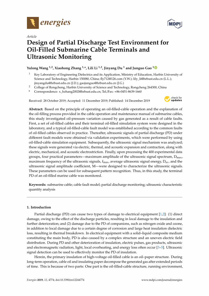
Figure 1 illustrates the structure of a 500 kV, oil-filled submarine cable.
Energies 2020, 13, x FOR PEER REVIEW 2 of 14
decomposed gas subsequently dissolves in the cable oil, thereby resulting in variations in the cable oil pressure.
Figure 1 illustrates the structure of a 500 kV, oil-filled submarine cable.
Figure 1. Structure of a 500 kV, oil-filled submarine cable. 1. Oil channel; 2. conductor; 3. conductor shield; 4. insulation; 5. insulation shield; 6. copper braid belt; 7. alloy lead sleeve; 8. copper braid; 9. reinforcement layer; 10. cushion belt; 11. internal anticorrosive layer; 12. mothproof layer; 13. cushion belt; 14. sheath; 15. outer coating.
The high-voltage cable terminal [6–8] is an indispensable accessory for connecting other electrical equipment when high-voltage cables are laid. It is widely used for cable circuits with a voltage level of 110 kV and above. Furthermore, oil-filled terminals account for the majority of high-voltage cable terminals. The primary component of oil-filled terminals is the layer of insulation shielding at the end of the cable that is equipped with a stress cone to achieve better electric field distribution in the casing, as compared to that in ceramic or composite materials. Normally, silicone oil or an insulating medium, such as polybutylene or polyisobutylene, is filled between the stress cone and the bushing at the end of the cable, for the purpose of insulation. The probability of the failure of the power cable circuit failure based on previous incidents indicates that the probabilities of the failures of the intermediate connector and the cable terminal account for approximately 67% of the total failure of the cable circuit [9]. Therefore, the insulation quality of the cable terminal directly affects the safe operation of the entire cable circuit, as the terminal is a key connecting device in the cable circuit.
For oil-filled submarine cable terminals, voltage transformers are not installed in the terminals at both ends of the oil-filled cable. Therefore, the actual voltage signals to ground at the two ends of the cable cannot be obtained, making it impossible to test the insulation performance of the cable. However, the ultrasonic method can be used to monitor the high-voltage terminals of oil-filled submarine cables, to realize warnings of the imminent faults.
The ultrasonic method can effectively reduce electromagnetic interference [10]. Implementation of online monitoring for this method is easy. Furthermore, this method supports noninvasive detection, is simple to implement, and has been widely employed in transformers and gas-insulated substations (GIS), capacitors, motors, cables, and cable terminal power equipment, such as those presented in [11,12]. Furthermore, GIS-electric-joint detection or sound-by-voice detection in transformers has also been realized.
Richárd Cselkó et al. [13] simulated a 10 kV cable termination semiconductor layer scratch with a heat-shrinkable air-gap tube with six defect types, while simultaneously employing the pulse current and ultrasonic methods for PD measurement and the acoustic detection method that employs
Figure 1. Structure of a 500 kV, oil-filled submarine cable. 1. Oil channel; 2. conductor; 3. conductorshield; 4. insulation; 5. insulation shield; 6. copper braid belt; 7. alloy lead sleeve; 8. copper braid;9. reinforcement layer; 10. cushion belt; 11. internal anticorrosive layer; 12. mothproof layer; 13. cushionbelt; 14. sheath; 15. outer coating.
The high-voltage cable terminal [6–8] is an indispensable accessory for connecting other electricalequipment when high-voltage cables are laid. It is widely used for cable circuits with a voltage levelof 110 kV and above. Furthermore, oil-filled terminals account for the majority of high-voltage cableterminals. The primary component of oil-filled terminals is the layer of insulation shielding at theend of the cable that is equipped with a stress cone to achieve better electric field distribution in thecasing, as compared to that in ceramic or composite materials. Normally, silicone oil or an insulatingmedium, such as polybutylene or polyisobutylene, is filled between the stress cone and the bushingat the end of the cable, for the purpose of insulation. The probability of the failure of the powercable circuit failure based on previous incidents indicates that the probabilities of the failures of theintermediate connector and the cable terminal account for approximately 67% of the total failure of thecable circuit [9]. Therefore, the insulation quality of the cable terminal directly affects the safe operationof the entire cable circuit, as the terminal is a key connecting device in the cable circuit.
For oil-filled submarine cable terminals, voltage transformers are not installed in the terminals atboth ends of the oil-filled cable. Therefore, the actual voltage signals to ground at the two ends of thecable cannot be obtained, making it impossible to test the insulation performance of the cable. However,the ultrasonic method can be used to monitor the high-voltage terminals of oil-filled submarine cables,to realize warnings of the imminent faults.
The ultrasonic method can effectively reduce electromagnetic interference [10]. Implementation ofonline monitoring for this method is easy. Furthermore, this method supports noninvasive detection,is simple to implement, and has been widely employed in transformers and gas-insulated substations(GIS), capacitors, motors, cables, and cable terminal power equipment, such as those presentedin [11,12]. Furthermore, GIS-electric-joint detection or sound-by-voice detection in transformers hasalso been realized.
Energies 2019, 12, 4774 3 of 14
Richárd Cselkó et al. [13] simulated a 10 kV cable termination semiconductor layer scratch witha heat-shrinkable air-gap tube with six defect types, while simultaneously employing the pulse currentand ultrasonic methods for PD measurement and the acoustic detection method that employs a glassfiber guide, to introduce the ultrasonic sensor based on the axial and radial axes at 5 mm intervalsper point. Richárd Cselkó et al. [13] also obtained the cable terminal PD ultrasonic RMS, periodiccomponent peak, 50-Hz-related component, and 100-Hz-related component and detected positionrelations. According to their study, the 100-Hz-related component has the highest sensitivity anddynamic range, and it is less sensitive to external noise or noise interference caused by accidentalwaveguide rod movement. Within a certain range, when the voltage gradually increases, the dischargequantity measured by the pulse current method becomes approximately linearly related to the amplitudeof the 100-Hz-related components. Markalous et al. [14] used the ultrasonic and ultrahigh-frequencymethods to detect and locate the local electricity inside the transformer. Their results showed thata combination of the ultrahigh-frequency and ultrasonic methods could overcome the disadvantagesof the ultrasonic method in terms of positioning by using the time difference between PD signalsand the sensor. Such a combination of the two methods can improve both detection and positioningaccuracies. Suwarno et al. [15] used the ultrasonic method to detect PD in a gas-insulated substation.By analyzing the frequency spectrum, amplitude, and number of signals in unit time of the ultrasonicsignals collected on site, the ultrasonic method could enable detection of typical discharge signals,such as suspension potentials and pin-plate discharges. Wang et al. [16] built the 110 kV XLPEcable intermediate connector at the Sumitomo company, to simulate the four defects of air gap, burr,slide-flash, and suspension discharges in the terminal. The ultrasonic waveforms of the four typesof defects were obtained by placing the piezoelectric sensors directly on the outside of the cable’smiddle connector.
This article mainly studies from the perspective of oil-pressure changes caused by gas generatedby cable failure. We learned the operation of oil-filled cables and the principle of oil replenishmentintroduced in the submarine cable operation and maintenance manual, and then we designed anoil-filled cable and its terminal recharge simulation system in the laboratory. Additionally, consideringthe commonly occurring faults in an oil-filled cable during actual operation, a typical oil-filled cablefault model was also established.
Using the research platform of a typical fault model of oil-filled cable equipment, the oil-filled-cablesimulation equipment was experimentally verified, the ultrasonic generation mechanism of PDwas discussed, the frequency spectrum of different types of PD ultrasonic was analyzed, and thecharacteristics of local discharge signals were summarized.
2. Test-Device Design
PD is the main manifestation of the early stage of faults in an oil-filled cable terminal, the mainfactor causing further aging of the terminal insulation, and an important characteristic of the terminalinsulation state.
2.1. Oil-Cycle Simulation System
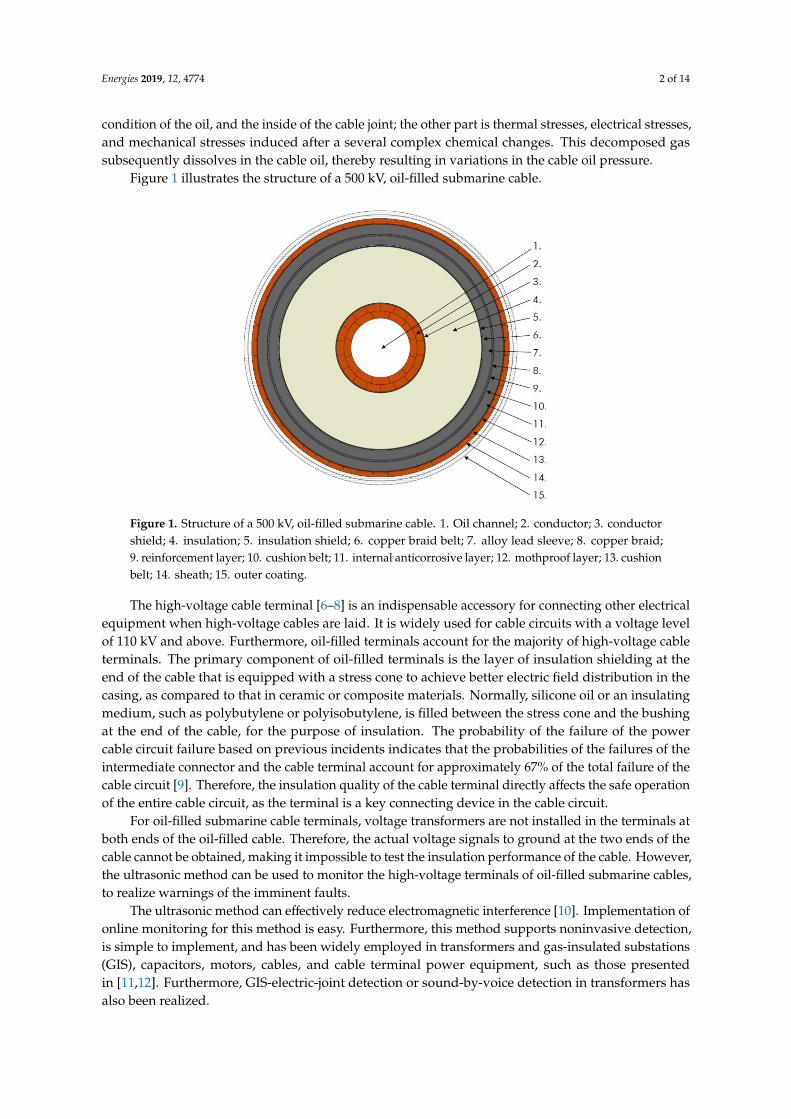
Under normal operating conditions of the cable circuit, the variation in oil pressure remainsminimal. In this study, to simulate the changes in the oil pressure in submarine cables, an oil circulationsystem was built in the laboratory, to simulate the possible faults in the cables. The system wasemployed to simulate the faults in the cable, e.g., PD and local overheating of degradation products,including the variation of oil pressure within the oil-filled cable being monitored. Figure 2 shows thecomposition of the simulated oil-path system. The system mainly comprises three parts:
• An oil-pressure-variation simulation unit for an oil-filled cable;• An oil-filled cable-terminal refueling-tank simulation unit;• A computer data acquisition and control unit.
Energies 2019, 12, 4774 4 of 14Energies 2020, 13, x FOR PEER REVIEW 4 of 14
Figure 2. Schematic of the oil circuit system simulating oil-pressure variation in an oil-filled cable.
2.2. Design of Simulation Unit for Oil-Pressure Variation in Oil-Filled Cable
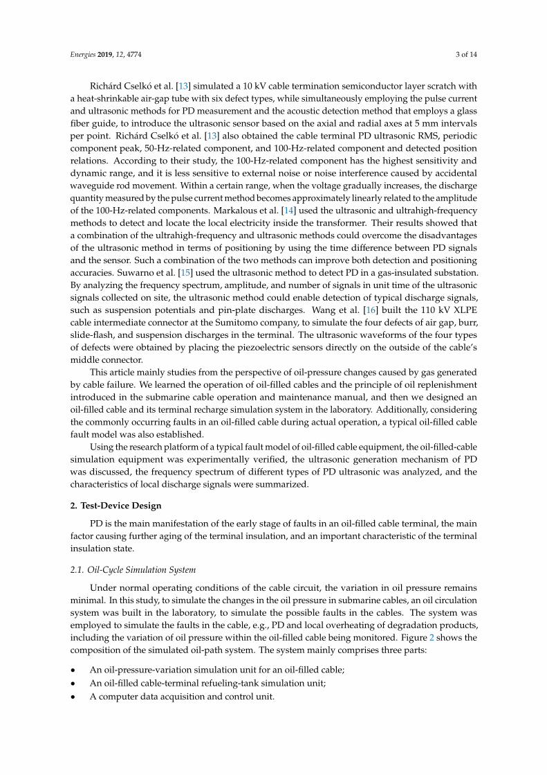
A sealed pressure vessel was used as the test chamber to monitor oil pressure. To ensure that the vessel was airtight and safe, three valves were installed in the pipeline, as shown in Figure 3:
(1) High-pressure valve: Owing to the simulated fault gas production, the oil pressure in the tank increased. After monitoring the oil pressure, the high-pressure valve was opened in order to allow oil and gas to flow into the oil-filling system, to achieve the system pressure.
(2) Check valve: After opening the high-pressure valve, the oil and gas smoothly flowed through the check valve into the oil-filling system. This is because the check valve has directionality, can effectively avoid oil and gas backflow, and can complete the decompression process.
(3) Low-pressure valve: After the tank simulating the cable was relieved of pressure, the liquid level inside the tank dropped. At this time, the low-pressure valve was opened in order to enable the cable oil in the oil-filling system to independently fill the tank because of gravity, until the whole tank was filled, to prepare for the next experiment.
Figure 3. Schematic of valve setting in oil-pressure-monitoring test chamber.
Generally, there are two reasons for the oil-pressure variation in the oil-filled cable. The second reason is that the cable’s oil-pressure variation is caused by the by-product of PD. For this reason, we designed individual closed-tank test chambers for the thermal aging and PD tests. This article mainly describes the local release test.
Figure 2. Schematic of the oil circuit system simulating oil-pressure variation in an oil-filled cable.
2.2. Design of Simulation Unit for Oil-Pressure Variation in Oil-Filled Cable
A sealed pressure vessel was used as the test chamber to monitor oil pressure. To ensure that thevessel was airtight and safe, three valves were installed in the pipeline, as shown in Figure 3:
(1) High-pressure valve: Owing to the simulated fault gas production, the oil pressure in the tankincreased. After monitoring the oil pressure, the high-pressure valve was opened in order toallow oil and gas to flow into the oil-filling system, to achieve the system pressure.
(2) Check valve: After opening the high-pressure valve, the oil and gas smoothly flowed throughthe check valve into the oil-filling system. This is because the check valve has directionality, caneffectively avoid oil and gas backflow, and can complete the decompression process.
(3) Low-pressure valve: After the tank simulating the cable was relieved of pressure, the liquid levelinside the tank dropped. At this time, the low-pressure valve was opened in order to enable thecable oil in the oil-filling system to independently fill the tank because of gravity, until the wholetank was filled, to prepare for the next experiment.
Energies 2020, 13, x FOR PEER REVIEW 4 of 14
Figure 2. Schematic of the oil circuit system simulating oil-pressure variation in an oil-filled cable.
2.2. Design of Simulation Unit for Oil-Pressure Variation in Oil-Filled Cable
A sealed pressure vessel was used as the test chamber to monitor oil pressure. To ensure that the vessel was airtight and safe, three valves were installed in the pipeline, as shown in Figure 3:
(1) High-pressure valve: Owing to the simulated fault gas production, the oil pressure in the tank increased. After monitoring the oil pressure, the high-pressure valve was opened in order to allow oil and gas to flow into the oil-filling system, to achieve the system pressure.
(2) Check valve: After opening the high-pressure valve, the oil and gas smoothly flowed through the check valve into the oil-filling system. This is because the check valve has directionality, can effectively avoid oil and gas backflow, and can complete the decompression process.
(3) Low-pressure valve: After the tank simulating the cable was relieved of pressure, the liquid level inside the tank dropped. At this time, the low-pressure valve was opened in order to enable the cable oil in the oil-filling system to independently fill the tank because of gravity, until the whole tank was filled, to prepare for the next experiment.
Figure 3. Schematic of valve setting in oil-pressure-monitoring test chamber.
Generally, there are two reasons for the oil-pressure variation in the oil-filled cable. The second reason is that the cable’s oil-pressure variation is caused by the by-product of PD. For this reason, we designed individual closed-tank test chambers for the thermal aging and PD tests. This article mainly describes the local release test.
Figure 3. Schematic of valve setting in oil-pressure-monitoring test chamber.
Generally, there are two reasons for the oil-pressure variation in the oil-filled cable. The secondreason is that the cable’s oil-pressure variation is caused by the by-product of PD. For this reason,
Energies 2019, 12, 4774 5 of 14
we designed individual closed-tank test chambers for the thermal aging and PD tests. This articlemainly describes the local release test.
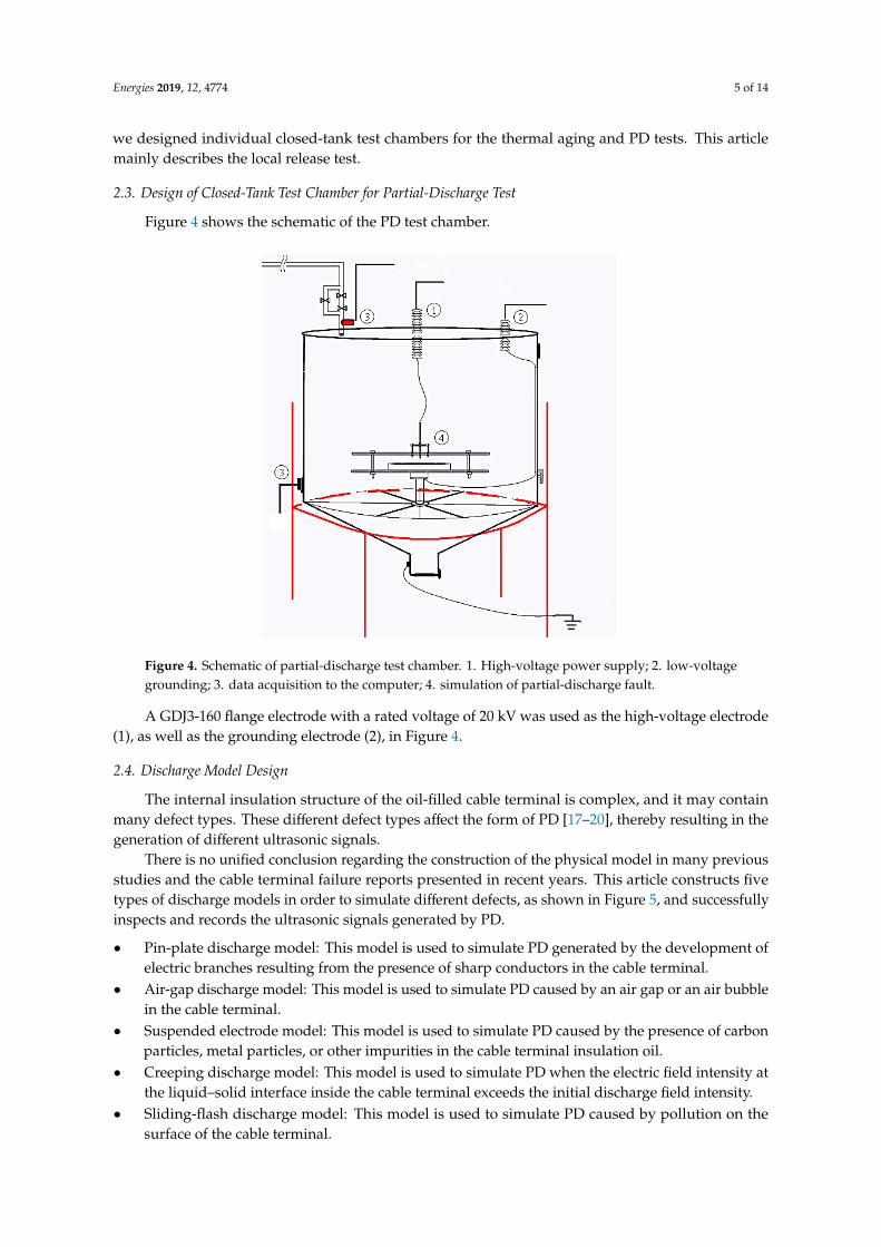
2.3. Design of Closed-Tank Test Chamber for Partial-Discharge Test
Figure 4 shows the schematic of the PD test chamber.
Energies 2020, 13, x FOR PEER REVIEW 5 of 14
2.3. Design of Closed-Tank Test Chamber for Partial-Discharge Test
Figure 4 shows the schematic of the PD test chamber.
Figure 4. Schematic of partial-discharge test chamber. 1. High-voltage power supply; 2. low-voltage grounding; 3. data acquisition to the computer; 4. simulation of partial-discharge fault.
A GDJ3-160 flange electrode with a rated voltage of 20 kV was used as the high-voltage electrode (1), as well as the grounding electrode (2), in Figure 4.
2.4. Discharge Model Design
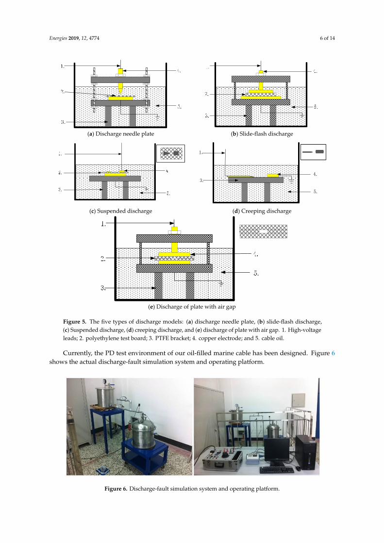
The internal insulation structure of the oil-filled cable terminal is complex, and it may contain many defect types. These different defect types affect the form of PD [17–20], thereby resulting in the generation of different ultrasonic signals.
There is no unified conclusion regarding the construction of the physical model in many previous studies and the cable terminal failure reports presented in recent years. This article constructs five types of discharge models in order to simulate different defects, as shown in Figure 5, and successfully inspects and records the ultrasonic signals generated by PD.
• Pin-plate discharge model: This model is used to simulate PD generated by the development of electric branches resulting from the presence of sharp conductors in the cable terminal.
• Air-gap discharge model: This model is used to simulate PD caused by an air gap or an air bubble in the cable terminal.
• Suspended electrode model: This model is used to simulate PD caused by the presence of carbon particles, metal particles, or other impurities in the cable terminal insulation oil.
• Creeping discharge model: This model is used to simulate PD when the electric field intensity at the liquid–solid interface inside the cable terminal exceeds the initial discharge field intensity.
• Sliding-flash discharge model: This model is used to simulate PD caused by pollution on the surface of the cable terminal.
Figure 4. Schematic of partial-discharge test chamber. 1. High-voltage power supply; 2. low-voltagegrounding; 3. data acquisition to the computer; 4. simulation of partial-discharge fault.
A GDJ3-160 flange electrode with a rated voltage of 20 kV was used as the high-voltage electrode(1), as well as the grounding electrode (2), in Figure 4.
2.4. Discharge Model Design
The internal insulation structure of the oil-filled cable terminal is complex, and it may containmany defect types. These different defect types affect the form of PD [17–20], thereby resulting in thegeneration of different ultrasonic signals.
There is no unified conclusion regarding the construction of the physical model in many previousstudies and the cable terminal failure reports presented in recent years. This article constructs fivetypes of discharge models in order to simulate different defects, as shown in Figure 5, and successfullyinspects and records the ultrasonic signals generated by PD.
• Pin-plate discharge model: This model is used to simulate PD generated by the development ofelectric branches resulting from the presence of sharp conductors in the cable terminal.
• Air-gap discharge model: This model is used to simulate PD caused by an air gap or an air bubblein the cable terminal.
• Suspended electrode model: This model is used to simulate PD caused by the presence of carbonparticles, metal particles, or other impurities in the cable terminal insulation oil.
• Creeping discharge model: This model is used to simulate PD when the electric field intensity atthe liquid–solid interface inside the cable terminal exceeds the initial discharge field intensity.
• Sliding-flash discharge model: This model is used to simulate PD caused by pollution on thesurface of the cable terminal.
Energies 2019, 12, 4774 6 of 14
Energies 2020, 13, x FOR PEER REVIEW 6 of 14
(a) Discharge needle plate (b) Slide-flash discharge
1.
3.
4.
5.
(c) Suspended discharge (d) Creeping discharge
(e) Discharge of plate with air gap
Figure 5. The five types of discharge models: (a) discharge needle plate, (b) slide-flash discharge, (c) Suspended discharge, (d) creeping discharge, and (e) discharge of plate with air gap. 1. High-voltage leads; 2. polyethylene test board; 3. PTFE bracket; 4. copper electrode; and 5. cable oil.
Currently, the PD test environment of our oil-filled marine cable has been designed. Figure 6 shows the actual discharge-fault simulation system and operating platform.
Figure 5. The five types of discharge models: (a) discharge needle plate, (b) slide-flash discharge,(c) Suspended discharge, (d) creeping discharge, and (e) discharge of plate with air gap. 1. High-voltageleads; 2. polyethylene test board; 3. PTFE bracket; 4. copper electrode; and 5. cable oil.
Currently, the PD test environment of our oil-filled marine cable has been designed. Figure 6shows the actual discharge-fault simulation system and operating platform.Energies 2020, 13, x FOR PEER REVIEW 7 of 14
Figure 6. Discharge-fault simulation system and operating platform.
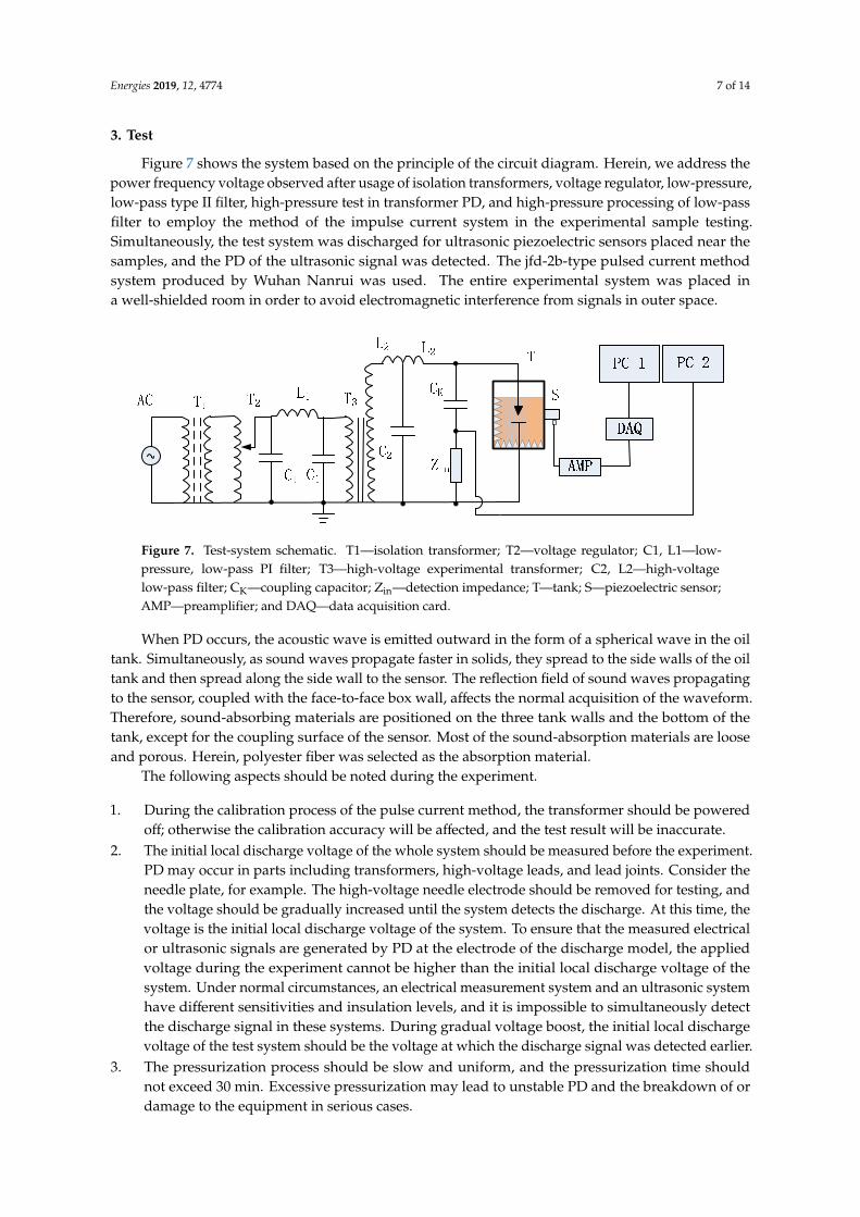
3. Test
Figure 7 shows the system based on the principle of the circuit diagram. Herein, we address the power frequency voltage observed after usage of isolation transformers, voltage regulator, low-pressure, low-pass type II filter, high-pressure test in transformer PD, and high-pressure processing of low-pass filter to employ the method of the impulse current system in the experimental sample testing. Simultaneously, the test system was discharged for ultrasonic piezoelectric sensors placed near the samples, and the PD of the ultrasonic signal was detected. The jfd-2b-type pulsed current method system produced by Wuhan Nanrui was used. The entire experimental system was placed in a well-shielded room in order to avoid electromagnetic interference from signals in outer space.
Figure 7. Test-system schematic. T1—isolation transformer; T2—voltage regulator; C1, L1—low-pressure, low-pass PI filter; T3—high-voltage experimental transformer; C2, L2—high-voltage low-pass filter; CK—coupling capacitor; Zin—detection impedance; T—tank; S—piezoelectric sensor; AMP—preamplifier; and DAQ—data acquisition card.
When PD occurs, the acoustic wave is emitted outward in the form of a spherical wave in the oil tank. Simultaneously, as sound waves propagate faster in solids, they spread to the side walls of the oil tank and then spread along the side wall to the sensor. The reflection field of sound waves propagating to the sensor, coupled with the face-to-face box wall, affects the normal acquisition of the waveform. Therefore, sound-absorbing materials are positioned on the three tank walls and the bottom of the tank, except for the coupling surface of the sensor. Most of the sound-absorption materials are loose and porous. Herein, polyester fiber was selected as the absorption material.
The following aspects should be noted during the experiment.
1. During the calibration process of the pulse current method, the transformer should be powered off; otherwise the calibration accuracy will be affected, and the test result will be inaccurate.
Figure 6. Discharge-fault simulation system and operating platform.
Energies 2019, 12, 4774 7 of 14
3. Test
Figure 7 shows the system based on the principle of the circuit diagram. Herein, we address thepower frequency voltage observed after usage of isolation transformers, voltage regulator, low-pressure,low-pass type II filter, high-pressure test in transformer PD, and high-pressure processing of low-passfilter to employ the method of the impulse current system in the experimental sample testing.Simultaneously, the test system was discharged for ultrasonic piezoelectric sensors placed near thesamples, and the PD of the ultrasonic signal was detected. The jfd-2b-type pulsed current methodsystem produced by Wuhan Nanrui was used. The entire experimental system was placed ina well-shielded room in order to avoid electromagnetic interference from signals in outer space.
Energies 2020, 13, x FOR PEER REVIEW 7 of 14
Figure 6. Discharge-fault simulation system and operating platform.
3. Test
Figure 7 shows the system based on the principle of the circuit diagram. Herein, we address the power frequency voltage observed after usage of isolation transformers, voltage regulator, low-pressure, low-pass type II filter, high-pressure test in transformer PD, and high-pressure processing of low-pass filter to employ the method of the impulse current system in the experimental sample testing. Simultaneously, the test system was discharged for ultrasonic piezoelectric sensors placed near the samples, and the PD of the ultrasonic signal was detected. The jfd-2b-type pulsed current method system produced by Wuhan Nanrui was used. The entire experimental system was placed in a well-shielded room in order to avoid electromagnetic interference from signals in outer space.
Figure 7. Test-system schematic. T1—isolation transformer; T2—voltage regulator; C1, L1—low-pressure, low-pass PI filter; T3—high-voltage experimental transformer; C2, L2—high-voltage low-pass filter; CK—coupling capacitor; Zin—detection impedance; T—tank; S—piezoelectric sensor; AMP—preamplifier; and DAQ—data acquisition card.
When PD occurs, the acoustic wave is emitted outward in the form of a spherical wave in the oil tank. Simultaneously, as sound waves propagate faster in solids, they spread to the side walls of the oil tank and then spread along the side wall to the sensor. The reflection field of sound waves propagating to the sensor, coupled with the face-to-face box wall, affects the normal acquisition of the waveform. Therefore, sound-absorbing materials are positioned on the three tank walls and the bottom of the tank, except for the coupling surface of the sensor. Most of the sound-absorption materials are loose and porous. Herein, polyester fiber was selected as the absorption material.
The following aspects should be noted during the experiment.
1. During the calibration process of the pulse current method, the transformer should be powered off; otherwise the calibration accuracy will be affected, and the test result will be inaccurate.
Figure 7. Test-system schematic. T1—isolation transformer; T2—voltage regulator; C1, L1—low-pressure, low-pass PI filter; T3—high-voltage experimental transformer; C2, L2—high-voltagelow-pass filter; CK—coupling capacitor; Zin—detection impedance; T—tank; S—piezoelectric sensor;AMP—preamplifier; and DAQ—data acquisition card.
When PD occurs, the acoustic wave is emitted outward in the form of a spherical wave in the oiltank. Simultaneously, as sound waves propagate faster in solids, they spread to the side walls of the oiltank and then spread along the side wall to the sensor. The reflection field of sound waves propagatingto the sensor, coupled with the face-to-face box wall, affects the normal acquisition of the waveform.Therefore, sound-absorbing materials are positioned on the three tank walls and the bottom of thetank, except for the coupling surface of the sensor. Most of the sound-absorption materials are looseand porous. Herein, polyester fiber was selected as the absorption material.
The following aspects should be noted during the experiment.
1. During the calibration process of the pulse current method, the transformer should be poweredoff; otherwise the calibration accuracy will be affected, and the test result will be inaccurate.
2. The initial local discharge voltage of the whole system should be measured before the experiment.PD may occur in parts including transformers, high-voltage leads, and lead joints. Consider theneedle plate, for example. The high-voltage needle electrode should be removed for testing, andthe voltage should be gradually increased until the system detects the discharge. At this time, thevoltage is the initial local discharge voltage of the system. To ensure that the measured electricalor ultrasonic signals are generated by PD at the electrode of the discharge model, the appliedvoltage during the experiment cannot be higher than the initial local discharge voltage of thesystem. Under normal circumstances, an electrical measurement system and an ultrasonic systemhave different sensitivities and insulation levels, and it is impossible to simultaneously detectthe discharge signal in these systems. During gradual voltage boost, the initial local dischargevoltage of the test system should be the voltage at which the discharge signal was detected earlier.
3. The pressurization process should be slow and uniform, and the pressurization time shouldnot exceed 30 min. Excessive pressurization may lead to unstable PD and the breakdown of ordamage to the equipment in serious cases.
Energies 2019, 12, 4774 8 of 14
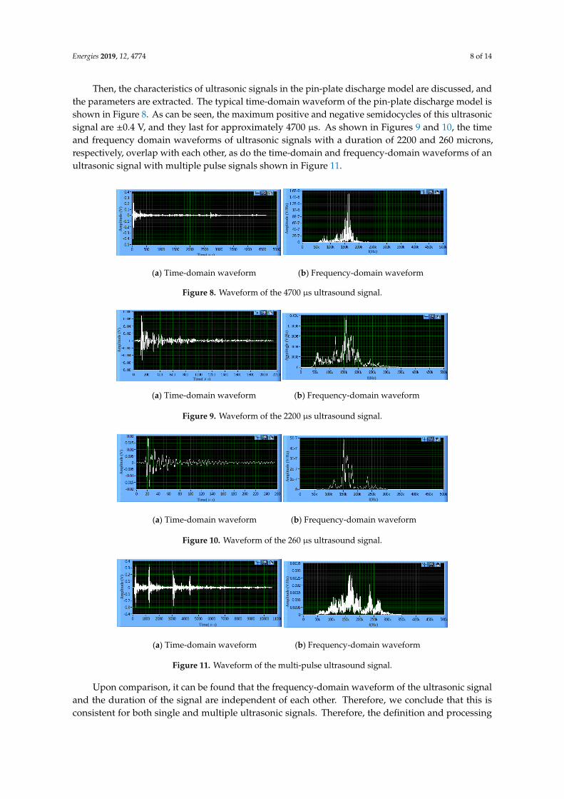
Then, the characteristics of ultrasonic signals in the pin-plate discharge model are discussed, andthe parameters are extracted. The typical time-domain waveform of the pin-plate discharge model isshown in Figure 8. As can be seen, the maximum positive and negative semidocycles of this ultrasonicsignal are ±0.4 V, and they last for approximately 4700 µs. As shown in Figures 9 and 10, the timeand frequency domain waveforms of ultrasonic signals with a duration of 2200 and 260 microns,respectively, overlap with each other, as do the time-domain and frequency-domain waveforms of anultrasonic signal with multiple pulse signals shown in Figure 11.
Energies 2020, 13, x FOR PEER REVIEW 8 of 14
2. The initial local discharge voltage of the whole system should be measured before the
experiment. PD may occur in parts including transformers, high-voltage leads, and lead joints.
Consider the needle plate, for example. The high-voltage needle electrode should be removed
for testing, and the voltage should be gradually increased until the system detects the discharge.
At this time, the voltage is the initial local discharge voltage of the system. To ensure that the
measured electrical or ultrasonic signals are generated by PD at the electrode of the discharge
model, the applied voltage during the experiment cannot be higher than the initial local
discharge voltage of the system. Under normal circumstances, an electrical measurement system
and an ultrasonic system have different sensitivities and insulation levels, and it is impossible
to simultaneously detect the discharge signal in these systems. During gradual voltage boost,
the initial local discharge voltage of the test system should be the voltage at which the discharge
signal was detected earlier.
3. The pressurization process should be slow and uniform, and the pressurization time should not
exceed 30 min. Excessive pressurization may lead to unstable PD and the breakdown of or
damage to the equipment in serious cases.
Then, the characteristics of ultrasonic signals in the pin-plate discharge model are discussed, and
the parameters are extracted. The typical time-domain waveform of the pin-plate discharge model is
shown in Figure 8. As can be seen, the maximum positive and negative semidocycles of this ultrasonic
signal are ±0.4 V, and they last for approximately 4700 μs. As shown in Figures 9 and 10, the time and
frequency domain waveforms of ultrasonic signals with a duration of 2200 and 260 microns,
respectively, overlap with each other, as do the time-domain and frequency-domain waveforms of
an ultrasonic signal with multiple pulse signals shown in Figure 11.
Am
pli
tude
(V)
Time(μs)
Am
pli
tud
e (V
/Hz)
f(Hz)
(a) Time-domain waveform (b) Frequency-domain waveform
Figure 8. Waveform of the 4700 μs ultrasound signal. (a) Time-domain waveform. (b) Frequency-
domain waveform.
Am
pli
tud
e (V
)
Time(μs)
Am
pli
tude
(V/H
z)
f(Hz)
(a) Time-domain waveform (b) Frequency-domain waveform
Figure 9. Waveform of the 2200 μs ultrasound signal. (a) Time-domain waveform. (b) Frequency-
domain waveform.
Figure 8. Waveform of the 4700 µs ultrasound signal.
Energies 2020, 13, x FOR PEER REVIEW 8 of 14
2. The initial local discharge voltage of the whole system should be measured before the
experiment. PD may occur in parts including transformers, high-voltage leads, and lead joints.
Consider the needle plate, for example. The high-voltage needle electrode should be removed
for testing, and the voltage should be gradually increased until the system detects the discharge.
At this time, the voltage is the initial local discharge voltage of the system. To ensure that the
measured electrical or ultrasonic signals are generated by PD at the electrode of the discharge
model, the applied voltage during the experiment cannot be higher than the initial local
discharge voltage of the system. Under normal circumstances, an electrical measurement system
and an ultrasonic system have different sensitivities and insulation levels, and it is impossible
to simultaneously detect the discharge signal in these systems. During gradual voltage boost,
the initial local discharge voltage of the test system should be the voltage at which the discharge
signal was detected earlier.
3. The pressurization process should be slow and uniform, and the pressurization time should not
exceed 30 min. Excessive pressurization may lead to unstable PD and the breakdown of or
damage to the equipment in serious cases.
Then, the characteristics of ultrasonic signals in the pin-plate discharge model are discussed, and
the parameters are extracted. The typical time-domain waveform of the pin-plate discharge model is
shown in Figure 8. As can be seen, the maximum positive and negative semidocycles of this ultrasonic
signal are ±0.4 V, and they last for approximately 4700 μs. As shown in Figures 9 and 10, the time and
frequency domain waveforms of ultrasonic signals with a duration of 2200 and 260 microns,
respectively, overlap with each other, as do the time-domain and frequency-domain waveforms of
an ultrasonic signal with multiple pulse signals shown in Figure 11.
Am
pli
tude
(V)
Time(μs)
Am
pli
tud
e (V
/Hz)
f(Hz)
(a) Time-domain waveform (b) Frequency-domain waveform
Figure 8. Waveform of the 4700 μs ultrasound signal. (a) Time-domain waveform. (b) Frequency-
domain waveform.
Am
pli
tud
e (V
)
Time(μs)
Am
pli
tude
(V/H
z)
f(Hz)
(a) Time-domain waveform (b) Frequency-domain waveform
Figure 9. Waveform of the 2200 μs ultrasound signal. (a) Time-domain waveform. (b) Frequency-
domain waveform.
Figure 9. Waveform of the 2200 µs ultrasound signal.Energies 2020, 13, x FOR PEER REVIEW 9 of 14
Am
pli
tud
e (V
)
Time(μs)
Am
pli
tude
(V/H
z)
f(Hz)
(a) Time-domain waveform (b) Frequency-domain waveform
Figure 10. Waveform of the 260 μs ultrasound signal. (a) Time-domain waveform. (b) Frequency-
domain waveform.
Am
pli
tud
e (V
)
Time(μs)
Am
pli
tude
(V/H
z)
f(Hz)
(a) Time-domain waveform (b) Frequency-domain waveform
Figure 11. Waveform of the multi-pulse ultrasound signal. (a) Time-domain waveform. (b)
Frequency-domain waveform.
Upon comparison, it can be found that the frequency-domain waveform of the ultrasonic signal
and the duration of the signal are independent of each other. Therefore, we conclude that this is
consistent for both single and multiple ultrasonic signals. Therefore, the definition and processing
method of an ultrasonic pulse signal in the software system introduced previously do not affect the
actual detection and analysis results.
Next, PD tests and signal analyses were carried out for the other four discharge models. Figure
12 shows a typical time-domain waveform and frequency-domain waveform of ultrasonic signal for
the air-gap discharge model. Figure 13 shows typical time-domain and frequency-domain waveforms
of ultrasonic signals for the suspended-electrode discharge model. Figure 14 shows typical time-
domain and frequency-domain waveforms of ultrasonic signal for the surface-discharge model.
Figure 15 shows the typical time-domain and frequency-domain waveforms of ultrasonic signal for
the sliding-flash discharge model.
Am
pli
tud
e (V
)
Time(μs)
Am
pli
tude
(V/H
z)
f(Hz)
(a) Time-domain waveform (b) Frequency-domain waveform
Figure 12. Ultrasound signal waveform of cavity discharge. (a) Time-domain waveform. (b)
Frequency-domain waveform.
Figure 10. Waveform of the 260 µs ultrasound signal.
Energies 2020, 13, x FOR PEER REVIEW 9 of 14
Am
pli
tud
e (V
)
Time(μs)
Am
pli
tude
(V/H
z)
f(Hz)
(a) Time-domain waveform (b) Frequency-domain waveform
Figure 10. Waveform of the 260 μs ultrasound signal. (a) Time-domain waveform. (b) Frequency-
domain waveform.
Am
pli
tud
e (V
)
Time(μs)
Am
pli
tude
(V/H
z)
f(Hz)
(a) Time-domain waveform (b) Frequency-domain waveform
Figure 11. Waveform of the multi-pulse ultrasound signal. (a) Time-domain waveform. (b)
Frequency-domain waveform.
Upon comparison, it can be found that the frequency-domain waveform of the ultrasonic signal
and the duration of the signal are independent of each other. Therefore, we conclude that this is
consistent for both single and multiple ultrasonic signals. Therefore, the definition and processing
method of an ultrasonic pulse signal in the software system introduced previously do not affect the
actual detection and analysis results.
Next, PD tests and signal analyses were carried out for the other four discharge models. Figure
12 shows a typical time-domain waveform and frequency-domain waveform of ultrasonic signal for
the air-gap discharge model. Figure 13 shows typical time-domain and frequency-domain waveforms
of ultrasonic signals for the suspended-electrode discharge model. Figure 14 shows typical time-
domain and frequency-domain waveforms of ultrasonic signal for the surface-discharge model.
Figure 15 shows the typical time-domain and frequency-domain waveforms of ultrasonic signal for
the sliding-flash discharge model.
Am
pli
tud
e (V
)
Time(μs)
Am
pli
tude
(V/H
z)
f(Hz)
(a) Time-domain waveform (b) Frequency-domain waveform
Figure 12. Ultrasound signal waveform of cavity discharge. (a) Time-domain waveform. (b)
Frequency-domain waveform.
Figure 11. Waveform of the multi-pulse ultrasound signal.
Upon comparison, it can be found that the frequency-domain waveform of the ultrasonic signaland the duration of the signal are independent of each other. Therefore, we conclude that this isconsistent for both single and multiple ultrasonic signals. Therefore, the definition and processing
Energies 2019, 12, 4774 9 of 14
method of an ultrasonic pulse signal in the software system introduced previously do not affect theactual detection and analysis results.
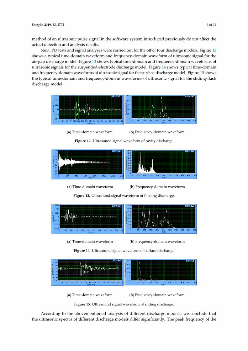
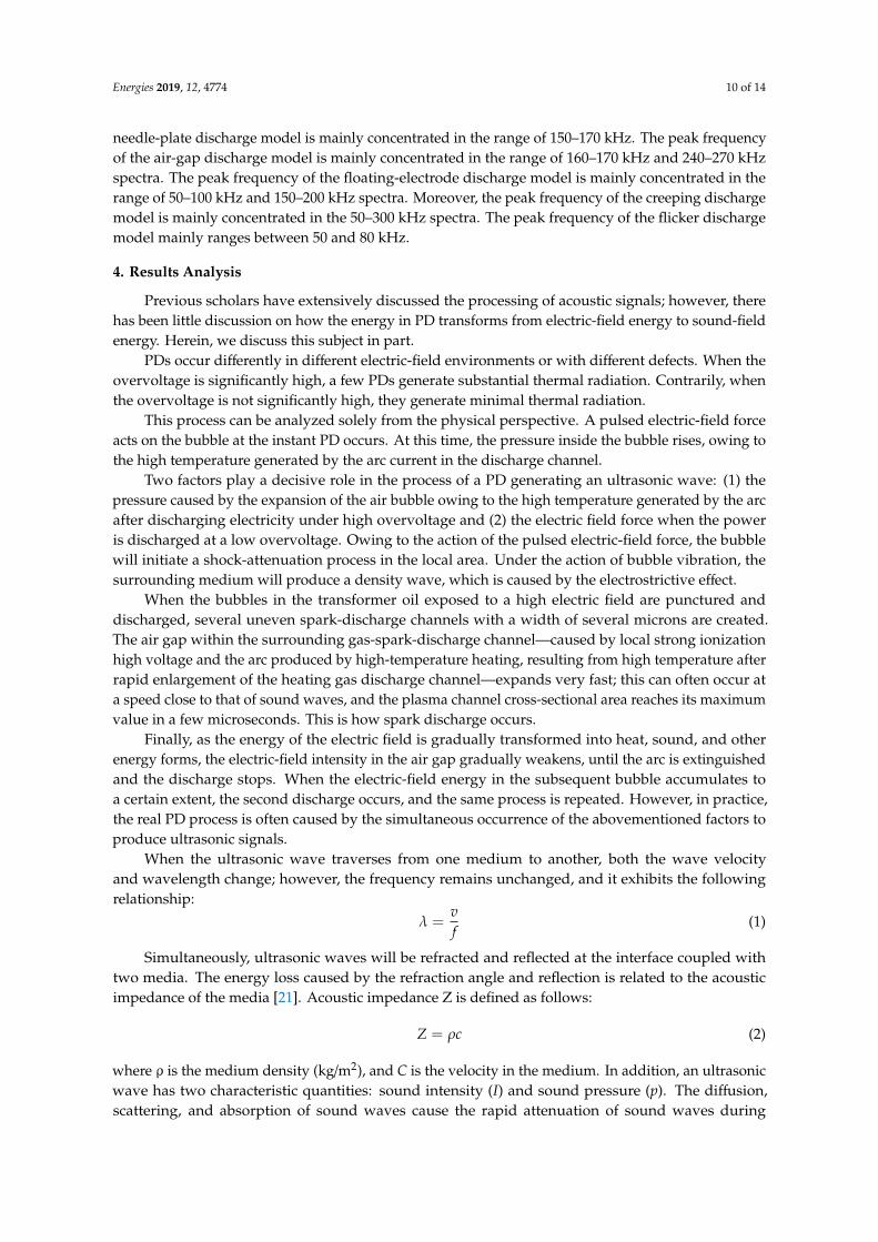
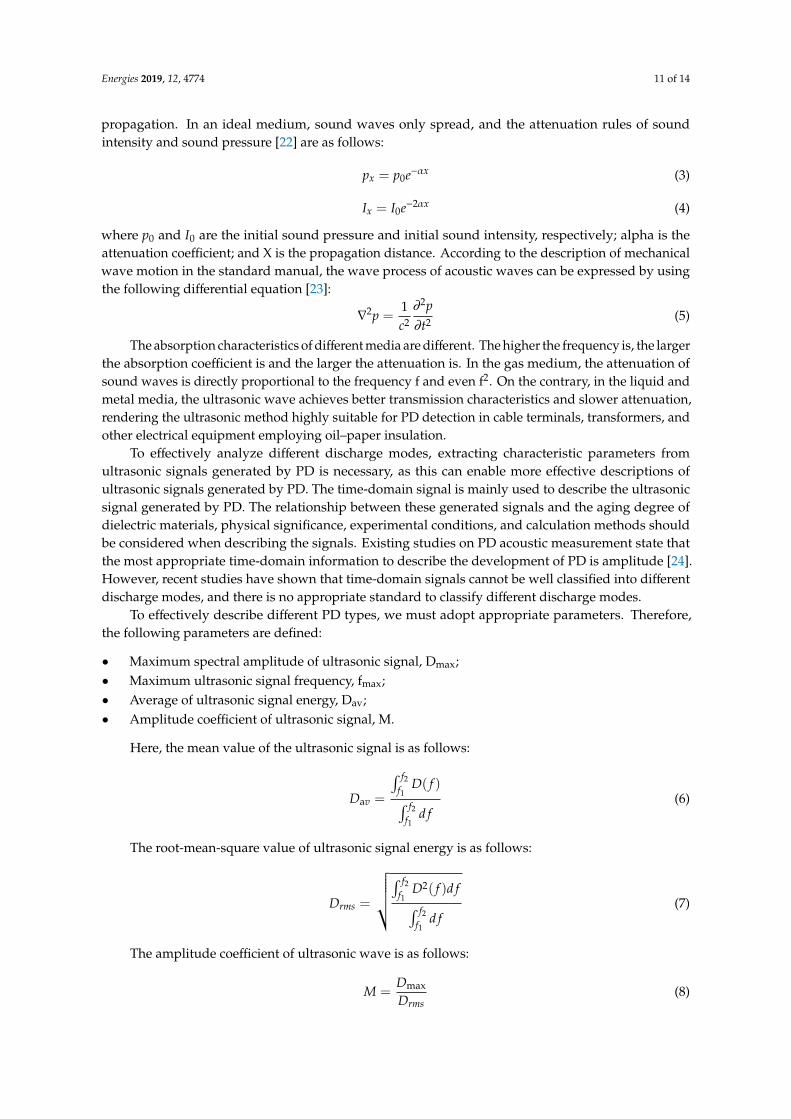
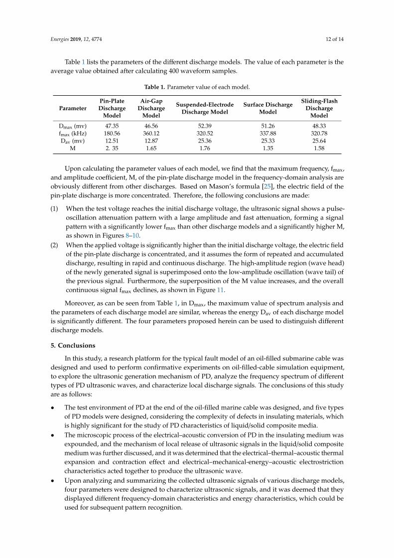
Next, PD tests and signal analyses were carried out for the other four discharge models. Figure 12shows a typical time-domain waveform and frequency-domain waveform of ultrasonic signal for theair-gap discharge model. Figure 13 shows typical time-domain and frequency-domain waveforms ofultrasonic signals for the suspended-electrode discharge model. Figure 14 shows typical time-domainand frequency-domain waveforms of ultrasonic signal for the surface-discharge model. Figure 15 showsthe typical time-domain and frequency-domain waveforms of ultrasonic signal for the sliding-flashdischarge model.
Energies 2020, 13, x FOR PEER REVIEW 9 of 14
Am
pli
tud
e (V
)
Time(μs)
Am
pli
tude
(V/H
z)
f(Hz)
(a) Time-domain waveform (b) Frequency-domain waveform
Figure 10. Waveform of the 260 μs ultrasound signal. (a) Time-domain waveform. (b) Frequency-
domain waveform.
Am
pli
tud
e (V
)
Time(μs)
Am
pli
tude
(V/H
z)
f(Hz)
(a) Time-domain waveform (b) Frequency-domain waveform
Figure 11. Waveform of the multi-pulse ultrasound signal. (a) Time-domain waveform. (b)
Frequency-domain waveform.
Upon comparison, it can be found that the frequency-domain waveform of the ultrasonic signal
and the duration of the signal are independent of each other. Therefore, we conclude that this is
consistent for both single and multiple ultrasonic signals. Therefore, the definition and processing
method of an ultrasonic pulse signal in the software system introduced previously do not affect the
actual detection and analysis results.
Next, PD tests and signal analyses were carried out for the other four discharge models. Figure
12 shows a typical time-domain waveform and frequency-domain waveform of ultrasonic signal for
the air-gap discharge model. Figure 13 shows typical time-domain and frequency-domain waveforms
of ultrasonic signals for the suspended-electrode discharge model. Figure 14 shows typical time-
domain and frequency-domain waveforms of ultrasonic signal for the surface-discharge model.
Figure 15 shows the typical time-domain and frequency-domain waveforms of ultrasonic signal for
the sliding-flash discharge model.
Am
pli
tud
e (V
)
Time(μs) A
mpli
tude
(V/H
z)
f(Hz)
(a) Time-domain waveform (b) Frequency-domain waveform
Figure 12. Ultrasound signal waveform of cavity discharge. (a) Time-domain waveform. (b)
Frequency-domain waveform.
Figure 12. Ultrasound signal waveform of cavity discharge.Energies 2020, 13, x FOR PEER REVIEW 10 of 14
Am
pli
tud
e (V
)
Time(μs)
Am
pli
tude
(V/H
z)
f(Hz)
(a) Time-domain waveform (b) Frequency-domain waveform
Figure 13. Ultrasound signal waveform of floating discharge. (a) Time-domain waveform. (b)
Frequency-domain waveform.
Am
pli
tud
e (V
)
Time(μs)
Am
pli
tud
e (V
/Hz)
f(Hz)
(a) Time-domain waveform (b) Frequency-domain waveform
Figure 14. Ultrasound signal waveform of surface discharge. (a) Time-domain waveform. (b)
Frequency-domain waveform.
Am
pli
tude
(V)
Time(μs)
Am
pli
tude
(V/H
z)
f(Hz)
(a) Time-domain waveform (b) Frequency-domain waveform
Figure 15. Ultrasound signal waveform of sliding discharge. (a) Time-domain waveform. (b)
Frequency-domain waveform.
According to the abovementioned analysis of different discharge models, we conclude that the
ultrasonic spectra of different discharge models differ significantly. The peak frequency of the needle-
plate discharge model is mainly concentrated in the range of 150–170 kHz. The peak frequency of the
air-gap discharge model is mainly concentrated in the range of 160–170 kHz and 240–270 kHz spectra.
The peak frequency of the floating-electrode discharge model is mainly concentrated in the range of
50–100 kHz and 150–200 kHz spectra. Moreover, the peak frequency of the creeping discharge model
is mainly concentrated in the 50–300 kHz spectra. The peak frequency of the flicker discharge model
mainly ranges between 50 and 80 kHz.
4. Results Analysis
Previous scholars have extensively discussed the processing of acoustic signals; however, there
has been little discussion on how the energy in PD transforms from electric-field energy to sound-
field energy. Herein, we discuss this subject in part.
PDs occur differently in different electric-field environments or with different defects. When the
overvoltage is significantly high, a few PDs generate substantial thermal radiation. Contrarily, when
the overvoltage is not significantly high, they generate minimal thermal radiation.
This process can be analyzed solely from the physical perspective. A pulsed electric-field force
acts on the bubble at the instant PD occurs. At this time, the pressure inside the bubble rises, owing
to the high temperature generated by the arc current in the discharge channel.
Figure 13. Ultrasound signal waveform of floating discharge.
Energies 2020, 13, x FOR PEER REVIEW 10 of 14
Am
pli
tud
e (V
)
Time(μs)
Am
pli
tude
(V/H
z)
f(Hz)
(a) Time-domain waveform (b) Frequency-domain waveform
Figure 13. Ultrasound signal waveform of floating discharge. (a) Time-domain waveform. (b)
Frequency-domain waveform.
Am
pli
tud
e (V
)
Time(μs)
Am
pli
tud
e (V
/Hz)
f(Hz)
(a) Time-domain waveform (b) Frequency-domain waveform
Figure 14. Ultrasound signal waveform of surface discharge. (a) Time-domain waveform. (b)
Frequency-domain waveform.
Am
pli
tude
(V)
Time(μs)
Am
pli
tude
(V/H
z)
f(Hz)
(a) Time-domain waveform (b) Frequency-domain waveform
Figure 15. Ultrasound signal waveform of sliding discharge. (a) Time-domain waveform. (b)
Frequency-domain waveform.
According to the abovementioned analysis of different discharge models, we conclude that the
ultrasonic spectra of different discharge models differ significantly. The peak frequency of the needle-
plate discharge model is mainly concentrated in the range of 150–170 kHz. The peak frequency of the
air-gap discharge model is mainly concentrated in the range of 160–170 kHz and 240–270 kHz spectra.
The peak frequency of the floating-electrode discharge model is mainly concentrated in the range of
50–100 kHz and 150–200 kHz spectra. Moreover, the peak frequency of the creeping discharge model
is mainly concentrated in the 50–300 kHz spectra. The peak frequency of the flicker discharge model
mainly ranges between 50 and 80 kHz.
4. Results Analysis
Previous scholars have extensively discussed the processing of acoustic signals; however, there
has been little discussion on how the energy in PD transforms from electric-field energy to sound-
field energy. Herein, we discuss this subject in part.
PDs occur differently in different electric-field environments or with different defects. When the
overvoltage is significantly high, a few PDs generate substantial thermal radiation. Contrarily, when
the overvoltage is not significantly high, they generate minimal thermal radiation.
This process can be analyzed solely from the physical perspective. A pulsed electric-field force
acts on the bubble at the instant PD occurs. At this time, the pressure inside the bubble rises, owing
to the high temperature generated by the arc current in the discharge channel.
Figure 14. Ultrasound signal waveform of surface discharge.
Energies 2020, 13, x FOR PEER REVIEW 10 of 14
Am
pli
tud
e (V
)
Time(μs)
Am
pli
tude
(V/H
z)
f(Hz)
(a) Time-domain waveform (b) Frequency-domain waveform
Figure 13. Ultrasound signal waveform of floating discharge. (a) Time-domain waveform. (b)
Frequency-domain waveform.
Am
pli
tud
e (V
)
Time(μs)
Am
pli
tud
e (V
/Hz)
f(Hz)
(a) Time-domain waveform (b) Frequency-domain waveform
Figure 14. Ultrasound signal waveform of surface discharge. (a) Time-domain waveform. (b)
Frequency-domain waveform.
Am
pli
tude
(V)
Time(μs)
Am
pli
tude
(V/H
z)
f(Hz)
(a) Time-domain waveform (b) Frequency-domain waveform
Figure 15. Ultrasound signal waveform of sliding discharge. (a) Time-domain waveform. (b)
Frequency-domain waveform.
According to the abovementioned analysis of different discharge models, we conclude that the
ultrasonic spectra of different discharge models differ significantly. The peak frequency of the needle-
plate discharge model is mainly concentrated in the range of 150–170 kHz. The peak frequency of the
air-gap discharge model is mainly concentrated in the range of 160–170 kHz and 240–270 kHz spectra.
The peak frequency of the floating-electrode discharge model is mainly concentrated in the range of
50–100 kHz and 150–200 kHz spectra. Moreover, the peak frequency of the creeping discharge model
is mainly concentrated in the 50–300 kHz spectra. The peak frequency of the flicker discharge model
mainly ranges between 50 and 80 kHz.
4. Results Analysis
Previous scholars have extensively discussed the processing of acoustic signals; however, there
has been little discussion on how the energy in PD transforms from electric-field energy to sound-
field energy. Herein, we discuss this subject in part.
PDs occur differently in different electric-field environments or with different defects. When the
overvoltage is significantly high, a few PDs generate substantial thermal radiation. Contrarily, when
the overvoltage is not significantly high, they generate minimal thermal radiation.
This process can be analyzed solely from the physical perspective. A pulsed electric-field force
acts on the bubble at the instant PD occurs. At this time, the pressure inside the bubble rises, owing
to the high temperature generated by the arc current in the discharge channel.
Figure 15. Ultrasound signal waveform of sliding discharge.
According to the abovementioned analysis of different discharge models, we conclude thatthe ultrasonic spectra of different discharge models differ significantly. The peak frequency of the
Energies 2019, 12, 4774 10 of 14
needle-plate discharge model is mainly concentrated in the range of 150–170 kHz. The peak frequencyof the air-gap discharge model is mainly concentrated in the range of 160–170 kHz and 240–270 kHzspectra. The peak frequency of the floating-electrode discharge model is mainly concentrated in therange of 50–100 kHz and 150–200 kHz spectra. Moreover, the peak frequency of the creeping dischargemodel is mainly concentrated in the 50–300 kHz spectra. The peak frequency of the flicker dischargemodel mainly ranges between 50 and 80 kHz.
4. Results Analysis
Previous scholars have extensively discussed the processing of acoustic signals; however, therehas been little discussion on how the energy in PD transforms from electric-field energy to sound-fieldenergy. Herein, we discuss this subject in part.
PDs occur differently in different electric-field environments or with different defects. When theovervoltage is significantly high, a few PDs generate substantial thermal radiation. Contrarily, whenthe overvoltage is not significantly high, they generate minimal thermal radiation.
This process can be analyzed solely from the physical perspective. A pulsed electric-field forceacts on the bubble at the instant PD occurs. At this time, the pressure inside the bubble rises, owing tothe high temperature generated by the arc current in the discharge channel.
Two factors play a decisive role in the process of a PD generating an ultrasonic wave: (1) thepressure caused by the expansion of the air bubble owing to the high temperature generated by the arcafter discharging electricity under high overvoltage and (2) the electric field force when the poweris discharged at a low overvoltage. Owing to the action of the pulsed electric-field force, the bubblewill initiate a shock-attenuation process in the local area. Under the action of bubble vibration, thesurrounding medium will produce a density wave, which is caused by the electrostrictive effect.
When the bubbles in the transformer oil exposed to a high electric field are punctured anddischarged, several uneven spark-discharge channels with a width of several microns are created.The air gap within the surrounding gas-spark-discharge channel—caused by local strong ionizationhigh voltage and the arc produced by high-temperature heating, resulting from high temperature afterrapid enlargement of the heating gas discharge channel—expands very fast; this can often occur ata speed close to that of sound waves, and the plasma channel cross-sectional area reaches its maximumvalue in a few microseconds. This is how spark discharge occurs.
Finally, as the energy of the electric field is gradually transformed into heat, sound, and otherenergy forms, the electric-field intensity in the air gap gradually weakens, until the arc is extinguishedand the discharge stops. When the electric-field energy in the subsequent bubble accumulates toa certain extent, the second discharge occurs, and the same process is repeated. However, in practice,the real PD process is often caused by the simultaneous occurrence of the abovementioned factors toproduce ultrasonic signals.
When the ultrasonic wave traverses from one medium to another, both the wave velocityand wavelength change; however, the frequency remains unchanged, and it exhibits the followingrelationship:
λ =vf
(1)
Simultaneously, ultrasonic waves will be refracted and reflected at the interface coupled withtwo media. The energy loss caused by the refraction angle and reflection is related to the acousticimpedance of the media [21]. Acoustic impedance Z is defined as follows:
Z = ρc (2)
where ρ is the medium density (kg/m2), and C is the velocity in the medium. In addition, an ultrasonicwave has two characteristic quantities: sound intensity (I) and sound pressure (p). The diffusion,scattering, and absorption of sound waves cause the rapid attenuation of sound waves during
Energies 2019, 12, 4774 11 of 14
propagation. In an ideal medium, sound waves only spread, and the attenuation rules of soundintensity and sound pressure [22] are as follows:
px = p0e−αx (3)
Ix = I0e−2αx (4)
where p0 and I0 are the initial sound pressure and initial sound intensity, respectively; alpha is theattenuation coefficient; and X is the propagation distance. According to the description of mechanicalwave motion in the standard manual, the wave process of acoustic waves can be expressed by usingthe following differential equation [23]:
∇2p =
1c2
∂2p∂t2 (5)
The absorption characteristics of different media are different. The higher the frequency is, the largerthe absorption coefficient is and the larger the attenuation is. In the gas medium, the attenuation ofsound waves is directly proportional to the frequency f and even f2. On the contrary, in the liquid andmetal media, the ultrasonic wave achieves better transmission characteristics and slower attenuation,rendering the ultrasonic method highly suitable for PD detection in cable terminals, transformers, andother electrical equipment employing oil–paper insulation.
To effectively analyze different discharge modes, extracting characteristic parameters fromultrasonic signals generated by PD is necessary, as this can enable more effective descriptions ofultrasonic signals generated by PD. The time-domain signal is mainly used to describe the ultrasonicsignal generated by PD. The relationship between these generated signals and the aging degree ofdielectric materials, physical significance, experimental conditions, and calculation methods shouldbe considered when describing the signals. Existing studies on PD acoustic measurement state thatthe most appropriate time-domain information to describe the development of PD is amplitude [24].However, recent studies have shown that time-domain signals cannot be well classified into differentdischarge modes, and there is no appropriate standard to classify different discharge modes.
To effectively describe different PD types, we must adopt appropriate parameters. Therefore,the following parameters are defined:
• Maximum spectral amplitude of ultrasonic signal, Dmax;• Maximum ultrasonic signal frequency, fmax;• Average of ultrasonic signal energy, Dav;• Amplitude coefficient of ultrasonic signal, M.
Here, the mean value of the ultrasonic signal is as follows:
Dav =
∫ f2f1
D( f )∫ f2f1
d f(6)
The root-mean-square value of ultrasonic signal energy is as follows:
Drms =
√√√√√√√∫ f2f1
D2( f )d f∫ f2f1
d f(7)
The amplitude coefficient of ultrasonic wave is as follows:
M =Dmax
Drms(8)
Energies 2019, 12, 4774 12 of 14
Table 1 lists the parameters of the different discharge models. The value of each parameter is theaverage value obtained after calculating 400 waveform samples.
Table 1. Parameter value of each model.
ParameterPin-PlateDischarge
Model
Air-GapDischarge
Model
Suspended-ElectrodeDischarge Model
Surface DischargeModel
Sliding-FlashDischarge
Model
Dmax (mv) 47.35 46.56 52.39 51.26 48.33fmax (kHz) 180.56 360.12 320.52 337.88 320.78Dav (mv) 12.51 12.87 25.36 25.33 25.64
M 2. 35 1.65 1.76 1.35 1.58
Upon calculating the parameter values of each model, we find that the maximum frequency, fmax,and amplitude coefficient, M, of the pin-plate discharge model in the frequency-domain analysis areobviously different from other discharges. Based on Mason’s formula [25], the electric field of thepin-plate discharge is more concentrated. Therefore, the following conclusions are made:
(1) When the test voltage reaches the initial discharge voltage, the ultrasonic signal shows a pulse-oscillation attenuation pattern with a large amplitude and fast attenuation, forming a signalpattern with a significantly lower fmax than other discharge models and a significantly higher M,as shown in Figures 8–10.
(2) When the applied voltage is significantly higher than the initial discharge voltage, the electric fieldof the pin-plate discharge is concentrated, and it assumes the form of repeated and accumulateddischarge, resulting in rapid and continuous discharge. The high-amplitude region (wave head)of the newly generated signal is superimposed onto the low-amplitude oscillation (wave tail) ofthe previous signal. Furthermore, the superposition of the M value increases, and the overallcontinuous signal fmax declines, as shown in Figure 11.
Moreover, as can be seen from Table 1, in Dmax, the maximum value of spectrum analysis andthe parameters of each discharge model are similar, whereas the energy Dav of each discharge modelis significantly different. The four parameters proposed herein can be used to distinguish differentdischarge models.
5. Conclusions
In this study, a research platform for the typical fault model of an oil-filled submarine cable wasdesigned and used to perform confirmative experiments on oil-filled-cable simulation equipment,to explore the ultrasonic generation mechanism of PD, analyze the frequency spectrum of differenttypes of PD ultrasonic waves, and characterize local discharge signals. The conclusions of this studyare as follows:
• The test environment of PD at the end of the oil-filled marine cable was designed, and five typesof PD models were designed, considering the complexity of defects in insulating materials, whichis highly significant for the study of PD characteristics of liquid/solid composite media.
• The microscopic process of the electrical–acoustic conversion of PD in the insulating medium wasexpounded, and the mechanism of local release of ultrasonic signals in the liquid/solid compositemedium was further discussed, and it was determined that the electrical–thermal–acoustic thermalexpansion and contraction effect and electrical–mechanical-energy–acoustic electrostrictioncharacteristics acted together to produce the ultrasonic wave.
• Upon analyzing and summarizing the collected ultrasonic signals of various discharge models,four parameters were designed to characterize ultrasonic signals, and it was deemed that theydisplayed different frequency-domain characteristics and energy characteristics, which could beused for subsequent pattern recognition.
Energies 2019, 12, 4774 13 of 14
Author Contributions: Conceptualization, Y.W.; data curation, L.L.; formal analysis, Y.W.; funding acquisition,X.Z.; investigation, J.G.; methodology, L.L.; software, J.D.; writing—original draft, Y.W.; writing—review andediting, X.Z.
Funding: This project was supported by the National Natural Science Foundation of China (Grant No. 51577045)and A Project of Shandong Province Higher Educational Science and Technology Program (Grant No. J17KB135).
Conflicts of Interest: The authors declare no conflicts of interest.
References
1. Schon, K. High Voltage Measurement Techniques: Fundamentals, Measuring Instruments, and Measuring Methods;Springer Nature Switzerland AG: Basel, Switzerland, 2019; pp. 369–425.
2. Tenbohlen, S.; Coenen, S.; Djamali, M.; Müller, A.; Samimi, M.H.; Siegel, M. Diagnostic measurements forpower transformers. Energies 2016, 9, 347. [CrossRef]
3. Wu, M.; Cao, H.; Cao, J.; Nguyen, H.L.; Gomes, J.B.; Krishnaswamy, S.P. An overview of state-of-the-artpartial discharge analysis techniques for condition monitoring. IEEE Electr. Insul. Mag. 2015, 31, 22–35.[CrossRef]
4. Morshuis, P.; Cavallini, A.; Fabiani, D.; Montanari, G.C.; Azcarraga, C. Stress conditions in HVDC equipmentand routes to in service failure. IEEE Trans. Dielectr. Electr. Insul. 2015, 22, 81–91. [CrossRef]
5. Harbaji, M.; Shaban, K.; El-Hag, A. Classification of common partial discharge types in oil-paper insulationsystem using acoustic signals. IEEE Trans. Dielectr. Electr. Insul. 2015, 22, 1674–1683. [CrossRef]
6. Tao, S.; Duan, D.; Wang, W.; Ren, Z.; Cheng, X.; Wu, L.; Li, M.; Qi, W. Research on the diagnostics andsimulation of high voltage XLPE cable terminal defects. In Proceedings of the 2016 International Conferenceon Condition Monitoring and Diagnosis (CMD), Xi’an, China, 25–28 September 2016; pp. 614–619.
7. Zhang, R.; Qiu, Z.; Wu, J.; Li, X.; Wang, S. Study on Gaseous Products in the Aging Process of SiliconeOil in Cable Terminals. In Proceedings of the 2018 IEEE Conference on Electrical Insulation and DielectricPhenomena (CEIDP), Cancun, Mexico, 21–24 October 2018; pp. 394–397.
8. Andrade, A.F.; Costa, E.G.; Andrade, F.L.; Soares, C.S.; Lira, G.R. Design of Cable Termination for ACBreakdown Voltage Tests. Energies 2019, 12, 3075. [CrossRef]
9. Kai, H. Methods and System Design of Partial Discharge Detecting of High-Voltage Cable Accessories; HunanUniversity: Changsha, China, 2010.
10. Ramírez-Niño, J.; Pascacio, A. Acoustic measuring of partial discharge in power transformers. Meas. Sci.Technol. 2009, 20, 2–6. [CrossRef]
11. Rubio-Serrano, J.; Rojas-Moreno, M.V.; Posada, J.; Martínez-Tarifa, J.M.; Robles, G.; Garcia-Souto, J.A.Electro-acoustic detection, identification and location of partial discharge sources in oil-paper insulationsystems. IEEE Trans. Dielectr. Electr. Insul. 2012, 19, 1569–1576. [CrossRef]
12. Honglei, L.; Fuxing, L.; Yongming, X.; Haigang, Z. Partial Discharge monitoring for cable terminals based onultrasonic. East China Electr. Power 2008, 36, 43–46.
13. Cselkó, R.; Tamus, Z.Á.; Szabó, A.; Berta, I. Comparison of acoustic and electrical partial dischargemeasurements on cable terminations. In Proceedings of the Conference Record of the 2010 IEEE InternationalSymposium on Electrical Insulation, San Diego, CA, USA, 6 June 2010; pp. 1–4.
14. Markalous, S.M.; Tenbohlen, S.; Feser, K. Detection and location of partial discharges in power transformersusing acoustic and electromagnetic signals. IEEE Trans. Dielectr. Electr. Insul. 2008, 15, 1576–1583. [CrossRef]
15. Caesario, P.; Anita, P. Partial discharge diagnosis of Gas Insulated Station using acoustic method.In Proceedings of the International Conference on Electrical Engineering and Informatics, Selangor, Malaysia,5 August 2009; pp. 667–671.
16. Wang, W.; Cheng, X.; Liu, C.; Yang, Z.; Huang, H.; Xue, Q. Study on the frequency spectrums of acousticemission PD signals in XLPE cable accessories. In Proceedings of the 2008 International Conference onCondition Monitoring and Diagnosis, Beijing, China, 21–24 April 2008; pp. 1246–1248.
17. Illias, H.A.; Tunio, M.A.; Bakar, A.H.; Mokhlis, H.; Chen, G. Partial discharge phenomena within an artificialvoid in cable insulation geometry: Experimental validation and simulation. IEEE Trans. Dielectr. Electr. Insul.2016, 23, 451–459. [CrossRef]
18. Robles, G.; Parrado-Hernández, E.; Ardila-Rey, J.; Martínez-Tarifa, J.M. Multiple partial discharge sourcediscrimination with multiclass support vector machines. Expert Syst. Appl. 2016, 55, 417–428. [CrossRef]
Energies 2019, 12, 4774 14 of 14
19. Borucki, S.; Łuczak, J.; Zmarzły, D. Using Clustering Methods for the Identification of Acoustic EmissionSignals Generated by the Selected Form of Partial Discharge in Oil-Paper Insulation. Arch. Coustics 2018, 43,207–215.
20. Wu, H.; Wang, H.; Zhang, P.; Huang, M.; Qi, B.; Rong, Z. The assess method of validity for partial dischargesensor based on multiple criterion. In Proceedings of the 2016 IEEE Conference on Electrical Insulation andDielectric Phenomena (CEIDP), Xi’an, China, 16–19 October 2016; pp. 330–333.
21. Chang Rong, Q.; Xiao Long, C. Electrical Insulation Testing Technology; Machine Press: Beijing, China, 2001;pp. 110–117.
22. Gutfleisch, F.; Niemeyer, L. Measurement and simulation of PD in epoxy voids. IEEE Trans. Dielectr.Electr. Insul. 1995, 2, 729–743. [CrossRef]
23. Yanqing, L.; Fangcheng, L.; Hongling, X.; Yongqiang, W. Study on ultrasonic generation mechanism of partialdischarge. IEEJ Technical Committee on Dielectrics and Electrical Insulation. In Proceedings of the 2005International Symposium on Electrical Insulating Materials, Kitakyushu, Japan, 5 June 2005; pp. 467–469.
24. Shady, S. A Review of Partial Discharge Detection Diagnosis Techniques in High Voltage Power Cables.In Proceedings of the 2018 IEEE 12th International Conference on Compatibility, Power Electronics andPower Engineering (CPE-POWERENG 2018), Doha, Qatar, 10–12 April 2018.
25. Ghosh, R.; Chatterjee, B.; Dalai, S. A Method for the Localization of Partial Discharge Sources using PartialDischarge Pulse Information from Acoustic Emissions. IEEE Trans. Dielectr. Electr. Insul. 2017, 24, 237–246.[CrossRef]
© 2019 by the authors. Licensee MDPI, Basel, Switzerland. This article is an open accessarticle distributed under the terms and conditions of the Creative Commons Attribution(CC BY) license (http://creativecommons.org/licenses/by/4.0/).