Embed Size (px)
Citation preview

$ 4 , X-611--66-537
'\ - ',
I
I .
OGO-E COSMIC RADIATION - NUCLEAR ABUNDANCE EXPERIMENT
, BY
S. 1. JONES G. H. LUDWIG D. E. STILWELL J. H. TRAINOR
I S. H. WAY
NOVEMBER 1966
/
I,: GODDARD SPACE FLIGHT CENTER J GREENBELT, MARYLAND r
/resented at the IEEE 13th Nuclear Science Symposium, ,/ Boston, Massachusetts, October 19 through 21, 1966. I
-
/

TABLE OF CONTENTS
Abst rac t . . . . . . . . . . . . . . . . . . Detec tor Systems
1. High Energy Detector . . . . . . . 2. Medium Energy Detec tor . . . . . . 3 . Low Energy Detector . . . . . . . .
Detector E lec t ron ic s
1. High Energy E lec t ron ic s System . . 2 . Medium Energy E lec t ron ic s System . 3 . Low Energy E l e c t r o n i c s System . . .
D i g i t a l System . . . . . . . . . . . . . . . Reference . . . . . . . . . . . . . . . . . Figure Captions . . . . . . . . . . . . . .
. . . . . . . . . . . 1
n . . . . . . . . . . . L . . . . . . . . . . . 2
. . . . . . . . . . . 2
. . . . . . . . . . . 3
. . . . . . . . . . . 4
. . . . . . . . . . . 5
. . . . . . . . . . . 6
. . . . . . . . . . . 9
. . . . . . . . . . . 9

OGO-E Cosmic Radia t ion - Nuclear Abundance Experiment*
S . L. Jones, G. H . Ludwig, D. E. S t i l w e l l , J . H. Trainor and S. H. Way
NASA/Goddard Space F l i g h t Center Greenbe 1 t , Mary land
Abstract
Information on t h e d e t a i l e d charge and energy s p e c t r a of g a l a c t i c and s o l a r cosmic rays i s requi red fo r a b e t t e r understanding of t he product ion , a c c e l e r a t i o n and modulation of those cosmic r ays . This experiment c o n s i s t s of a set of t h ree d e t e c t o r assemblies t o measure the d i f f e r e n t i a l energy s p e c t r a of protons and heav ie r n u c l e i through calcium (Z = 20) i n the range of 400 Kev t o 1 Bev/nucleon. ex tens ive e l e c t r o n i c s system t o implement the l o g i c , perform pu l se he igh t a n a l y s i s , measure p a r t i c l e f l u x e s , monitor experiment performance and i n t e r f a c e with the OGO d a t a system. The d e t e c t o r systems descr ibed he re a r e t h e des ign of F. B. McDonald, V. K. Balasubrahmanyan, D. E . Hagge, B. Teegarden and G. H. Ludwig of t h e Goddard Space F l i g h t Center .
This inc ludes an
* Presented a t the IEEE 13th Nuclear Science Symposium, Boston, Massachuset ts , October 19 through 2 1 , 1966.

DETECTOR SYSTEMS
High Energy Detector:
- Figure 1 shows the h ighes t energy de tec to r assembly schematical ly
- and l i s t s the major l og ic involved. S c i n t i l l a t o r s A and B a r e CsI(T1)
while t h e Cerenkov r a d i a t o r i s the one cm t h i c k sapphire window of t h e
photnt-:.-, k t i p l i e r tube.
the passage of a p a r t i c l e with energy from-50 Mev/nucleon t o 220 MeV/
nucleon. S imi l a r ly , ABC l o g i c a l events de f ine p a r t i c l e s with ene rg ie s
from 220 Mev/nucleon t o -1000 Mev/nucleon and the i n t e g r a l f l u x of
p a r t i c l e s with energ ies g r e a t e r than -1000 Mev/nucleon. Measurements of
t h e two s c i n t i l l a t i o n and the Cerenkov d e t e c t o r pu l se he igh t s i d e n t i f i e s
t he charge and energy of t he inc ident p a r t i c l e over the ind ica t ed ranges.
ABE events above appropr ia te th resholds de f ine
Medium Energy Detector:
This d e t e c t o r assembly and i t s log ic are shown i n Figure 2 . D and
FSlow are t h i n dE/dx C s I ( T 1 ) s c i n t i l l a t o r s while E i s a th i ck " t o t a l
energy" C s I s c i n t i l l a t o r ,
enc loses E .
E and Fslow pulses which w i l l i den t i fy charge and energy of t he p a r t i c l e
from -20 Mev/nucleon t o -300 Mev/nucleon. A l l events i n t h e D s c i n t i l l a t o r
a r e analyzed i n a f a s t , t h ree s t e p , i n t e g r a l pu l se he ight analyzer t o
provide f l u x and energy information during high f l u x s o l a r proton events .
Ffas t i s a p l a s t i c guard s c i n t i l l a t o r which
A DEFfast event enables p u l s e he igh t a n a l y s i s of t h e D,
Low Energy Detector :
This te lescope i s shown i n Figure 3 and i s composed of l a r g e a rea ,
t o t a l l y deple ted , su r f ace b a r r i e r s o l i d s t a t e d e t e c t o r s surrounded by a
2

guard s c i n t i l l a t o r . Detector G i s 100 microns t h i c k whi le H c o n s i s t s
of two 1000 micron d e t e c t o r s wi th the ou tpu t s summed.
events due t o p a r t i c l e s with energ ies from 3.5 Mev/nucleon t o 18.5 MeV/
nucleon, while f i v e i n t e g r a l d i sc r imina t ion l e v e l s on G provide f l u x
GHJ l og ic de f ines
and energy information f o r s o l a r f l a r e events .
Figure 4 i s a p i c t u r e of t hese d e t e c t o r assemblies , i nc lud ing t h e
high energy d e t e c t o r i n one h a l f of i t s f l i g h t c r a d l e .
inc ludes t h e d e t e c t o r s , photomul t ip l ie r tubes , p reampl i f i e r s , t he
Cockroft-Walton m u l t i p l i e r s on the base of each PM tube and t h e h igh
Each assembly
frequency o s c i l l a t o r which d r i v e s the m u l t i p l i e r s .
DETECTOR ELECTRONICS
High Energy E lec t ron ic s System:
Figure 5 dep ic t s t he two 256 channel and one 400 channel d i f -
f e r e n t i a l pu l se he igh t ana lyzers with a s soc ia t ed coincidence and ga in
changing c i r c u i t r y which make up t h i s e l e c t r o n i c s system. Most of t hese
c i r c u i t s were d iscussed i n d e t a i l i n a previous paper by Way, S t i l w e l l ,
and Jones (1966). Each pu l se he ight analyzer i s b a s i c a l l y i d e n t i c a l
wi th s l i g h t d i f f e rences i n s e n s i t i v i t i e s t o g ive t h e des i r ed dynamic
ranges. The s e n s i t i v i t i e s of the A and E ana lyzers a r e 1.0 and 12.0
m i l l i v o l t s pe r channel i n the high and low gain modes r e s p e c t i v e l y ,
whi le those of t he C analyzer are 0.5 and 4.0 m i l l i v o l t s pe r channel.
The dec i s ion t o change gain from one mode t o another (high t o low
ga in) i s done on an ind iv idua l event b a s i s with the A and B ana lyzers
changing toge ther and C changing independently. A pu l se summing c i r c u i t
i
3

f e d by t h e A and B pu l se s determines the ga in change p o i n t f o r A and B,
whi le t h e amplitude of t h e C p u l s e alone determines i f it i s t o be
analyzed i n h igh o r low gain.
The coincidence c i r c u i t i s a simple combination of monostables,
t unne l d iodes AND and I N H I B I T l og ic c i r c u i t s (Way, S t i l w e l l and Jones,
1966). The r e s o l u t i o n i s between 0.5 and 0.75 microseconds f o r rates
up t o 100,000 pps.
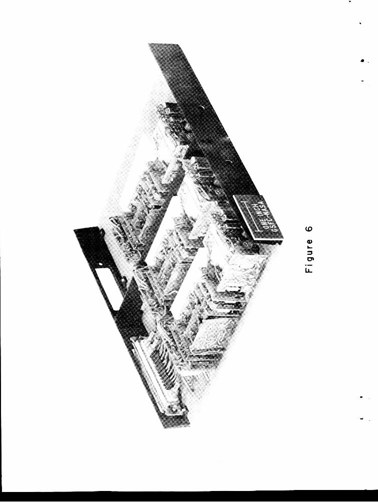
Measured performance of t h e e l e c t r o n i c s i s given b r i e f l y below:
I n t e g r a l l i n e a r i t y , analyzer - less than 1% over top 95% of sca l e ;
temperature s t a b i l i t y , ana lyzers - l e s s than + 0.5%, +5OC t o +40°C;
ze ro level o f f s e t - one channel; th resholds , A and B, ad jus t ab le - channel 2 . 0 t o channel 2.5; power consumption, a l l e l e c t r o n i c s - 250 m i l l i w a t t s .
t h r e e p u l s e he igh t ana lyzers .
-
Figure 6 i s a p i c t u r e of an e l e c t r o n i c s assembly con ta in ing
Medium Energy E lec t ron ic s System:
Three 256 channel d i f f e r e n t i a l p u l s e he igh t ana lyzers , one t h r e e
l e v e l i n t e g r a l pu l se he ight ana lyzer , co inc idence , ga in changing and
p u l s e shape d i sc r imina t ing , an t ico inc idence c i r c u i t r y make up these
e l e c t r o n i c s as shown i n F igure 7 . Each d i f f e r e n t i a l pu l se he igh t
ana lyzer i s i d e n t i c a l .
i s one m i l l i v o l t p e r channel and the low ga in s e n s i t i v i t y i s s i x t e e n
m i l l i v o l t s pe r channel. The maximum dynamic range i n e i t h e r h igh o r
low ga in i s 256 which i s determined by the accumulating capac i ty of
t h e d i g i t a l d a t a processor .
The bas i c high ga in s e n s i t i v i t y of each ana lyzer
-
4

The i n t e g r a l analyzer i s a simple tunne l diode d i sc r imina to r
c i r c u i t f ed by a s ta i r s t e p c u r r e n t genera tor (Figure 8 ) . Drive f o r
each of t h e ladder-adder r e s i s t o r s i s from a s t r i n g of commutator
b i n a r i e s t o be descr ibed wi th t h e d i g i t a l d a t a system. The f i r s t
l e v e l threshold and the fol lowing l e v e l widths a r e ad jus t ed by r e s i s t o r
va lue . Tr igger ing levels on t h e o rde r of 10 m i l l i v o l t s a r e t y p i c a l f o r
t he bot tom leve 1.
The coincidence c i r c u i t i s b a s i c a l l y the same as f o r t h e h igh
energy e l e c t r o n i c s wi th the a d d i t i o n of t h e an t ico inc idence log ic . The
pu l se shape d i sc r imina t ing c i r c u i t i s necessary t o sepa ra t e the pu l ses from
t h e p l a s t i c guard s c i n t i l l a t o r and the Cesium Iodide (Tl ) s c i n t i l l a t o r .
This i s done by d e t e c t i n g the pu l se peak and genera t ing an an t ico inc idence
pu l se a t t h a t t i m e . The t iming i n the coincidence c i r c u i t r y i s such
t h a t only a p l a s t i c s c i n t i l l a t i o n w i l l produce an an t ico inc idence p u l s e
soon enough t o prevent an a n a l y s i s of t he even t .
Low Energy E lec t ron ic s System:
The system shown i n Figure 9 provides f o r a dE/dx vs. E p a r t i c l e
a n a l y s i s using two 256 channel p u l s e he igh t ana lyzers and a 200
nanosecond coincidence r e so lv ing t i m e . Energy l o s s e s between 200 Kev
and 13 MeV i n t h e G d e t e c t o r , between 800 Kev and 77 Mev i n t h e H
d e t e c t o r and not g r e a t e r than about 200 Kev i n t h e guard s c i n t i l l a t o r
a r e requi red f o r pu l se he igh t a n a l y s i s . A f i v e level i n t e g r a l analyzer
s i m i l a r t o t ha t p rev ious ly descr ibed i s included t o monitor t h e l a rge
f l u x e s p re sen t dur ing s o l a r f l a r e events .
5

F a l l times of the G and H charge s e n s i t i v e p r e a n p l i f i e r s are set
f o r -10 microseconds t o in su re t h a t charge c o l l e c t i o n t i m e i s maximum.
The a c t i v e RC shapers provide pulse p i l e up r e j e c t i o n f o r t hese two
channels (Way, S t i l w e l l and Jones, 1966) . The f a l l time of t h e J
charge s e n s i t i v e p reampl i f i e r pu l se can be c l ipped t o 0.5 microsecond
s i n c e a f a s t p l a s t i c s c i n t i l l a t o r i s used, and thus a d d i t i o n a l shaping
i s not r equ i r ed t o permit high counting ra tes .
_ -
The system l i n e a r i t y i s 52.5% over the s p e c i f i e d energy ranges,
and over t h e temperature range of -10°C t o +5OoC. S igna l l imiters a r e
placed i n the amplifying cha ins t o minimize ampl i f i e r dead time due t o
h igh l e v e l s i g n a l s . The coincidence c i r c u i t r y u t i l i z e s non-sa tura t ing ,
I t unne l diode inpu t , boots t rap ampl i f i e r s and f a s t recovery t i m e mono-
s t a b l e s . The e n t i r e system i s constructed i n welded-wire modules us ing
a p r i n t e d c i r c u i t board f o r t he in te rconnec t . ,
C a l i b r a t i o n of t h e d e t e c t o r s and e l e c t r o n i c s i s performed wi th
a Van de Graaff a c c e l e r a t o r using the He3 on D2 r e a c t i o n t o ob ta in
pro tons up t o 17 MeV. Proton energy i s va r i ed a t t h e d e t e c t o r window
by i n s e r t i n g aluminum f o i l absorbers of known th ickness i n t h e beam
pa th .
DIGITAL SYSTEM
The d i g i t a l system accepts PHA pulse t r a i n s and ra te information
from t h e d e t e c t o r s as shown i n t h e block diagram (Figure 10) and
p resen t s t h e information t o t h e OGO c e n t r a l t e lemet ry system as ser ia l

spacec ra f t . The d i g i t a l system, shown i n g r e a t e r d e t a i l i n F igure 11,
c o n s i s t s b a s i c a l l y of two types of counters (shown as 9 - b i t counters
and a f loa t ing -po in t accumulator, o r FPA), c o n t r o l and readout modules,
a mul t ip lexer and a commutator. The c o n t r o l , readout and mul t ip l exe r
modules a r e redundant i n t h a t each of t h e s e boxes on t h e block diagram
corresponds t o two phys ica l ly sepa ra t e but i d e n t i c a l modules of t h e
appropr ia te type. To conserve power, ope ra t ing vo l t ages are appl ied
only t o one set of modules i n a given ope ra t ing mode. This i s repre-
sen ted by the "inputs" des igna ted Power I and Power 11.
- -
Each of t h e d e t e c t o r s A through H are a s soc ia t ed wi th a given
pu l se he ight ana lyzer and 9 -b i t counter wi th corresponding des igna t ions .
The counter may be opera ted e i t h e r as an 8 - b i t counter p l u s a s i n g l e
"set" r e g i s t e r o r as a convent ional 9 - b i t counter by s u i t a b l e connect ions
on t h e plug-in card . Only d e t e c t o r C uses the 9 - b i t con f igu ra t ion , a l l
remaining d e t e c t o r s u se 8 b i t s f o r 256 channels of p u l s e h e i g h t a n a l y s i s ,
and t h e 9 th b i t t o i n d i c a t e one of two p o s s i b l e conversion ga ins o r t o
provide information about t he mul t ip l exe r and commutator p o s i t i o n s . The
quas i - f loa t ing po in t accumulator c o n s i s t s of 5 count ing s t ages and 4 pre-
s c a l e r - s e l e c t i n g b i n a r i e s t o s e l e c t one of 16 s t ages of p re sca l ing .
The t o t a l count capac i ty of t h i s conf igu ra t ion i s 2,097,119 and t h e
maximum e r r o r i s 1 p a r t i n 32 , o r j u s t over 3%.
The 16 p o s i t i o n commutator s e q u e n t i a l l y selects one of e i g h t
d e t e c t o r rates o r one of e i g h t i n t e g r a l ana lyzer rates t o be counted
by t h e f l o a t i n g po in t accumulator. The i n t e g r a l ana lyzer l e v e l i s
s e l e c t e d by t h e commutator b i n a r i e s as previous ly descr ibed .
7

The system conf igu ra t ion accepts e igh t i n h i b i t s i g n a l s from one of
t h e two spacec ra f t d a t a encoders. The e i g h t words are d iv ided i n t o
four groups of two adjacent words each and d i r e c t e d t o the proper
- counters t o provide t h e read-out format shown i n Figure 12. Each
L
counter readout i s repea ted t o permit d e t e c t i o n of d a t a conta in ing
probable b i t e r r o r s , and t o provide redundancy i n t h e event of any
c o n t r o l c i r c u i t f a i l u r e s .
The d a t a processor w a s developed under c o n t r a c t wi th General
Ins t ruments , Inc. (H icksv i l l e , N. Y . ) us ing m u l t i p l e ch ip mic roc i r cu i t
technology. Discree t s i l i c o n ch ips for a l l a c t i v e and pass ive components
are a l loyed t o a ceramic s u b s t r a t e and in te rconnec ted by thermo-compression
bonded 1 m i l diameter soz id gold w i r e . Each such f l a t p a c k con ta ins a
complete c i r c u i t func t ion ( e . g . , ampl i f i e r s o r f l i p f l o p ) c o n s i s t i n g of
up t o 40 chips . The f l a t packs are packaged i n cordwood s t y l e and s o l i d -
po t t ed i n epoxy t o form the func t iona l modules shown i n t h e block diagram.
The complete d a t a process ing system, shown i n Figure 13, con ta ins over 2000
a c t i v e devides on a s i n g l e 5 112 x 7 112 x 1 inch p lug- in card .
c i r c u i t r y was designed t o ope ra t e properly with from 4.5 t o 9.0 v o l t s
supply vo l t age and throughout t h e temperature range -40°C t o +85OC a t
c locking speeds i n excess of 1 M Hz. Power consumption averages 2 .3
mwlbit .
The
8

REFERENCE
Way, S tan ley , D. S t i l w e l l and S . L. Jones , "A Three Parameter Pulse Height Analyzer and Coincidence System f o r S a t e l l i t e Cosmic Ray Studies , " IEEE Trans. Nuc. S c i . , NS-13, No. -
Figure 1:
Figure 2:
F igure 3:
Figure 4 :
Figure 5:
F igure 6:
Figure 7 :
Figure 8:
F igure 9:
Figure 10:
Figure 11:
Figure 12:
F igure 13:
1, 1966.
FIGURE CAPTIONS
Schematic of the h igh energy d e t e c t o r
Schematic of the medium energy d e t e c t o r
Schematic of the low energy d e t e c t o r
F l i g h t de t ec to r assemblies and c rad le s
E lec t ron ic s for t h e h igh energy system
P a r t i a l l y assembled e l e c t r o n i c s board wi th t h r e e d i f f e r e n t i a l pu l se he ight an a 1 y z er s
E lec t ron ic s fo r medium energy system
Basic i n t e g r a l pu l se he igh t analyzer
E lec t ron ic s for l o w energy system
Block diagram of the e n t i r e experiment
The bas i c d i g i t a l d a t a processor
Experiment da t a format
The d i g i t a l da t a processor packaged f o r space f l i g h t
9

z 0 W J 0 3 z
z 0 + H 0 LL Z
- a a
-
z
z 0 w --I u 5
n z
0 m a
1 a a a W I- z -
u) w I- U
m a d
W V >0 - I

v) I- J 3 v) W a
N
(u \
u 5 3
m I-
3 - a
d c v)
LL
.-
W I

m I- s - Q
a W W m z I- D- v, I-'rc) <u
0 W c
I

*

t B K
P In
x P ul a 0 In
J 0
I- z 0 0

. *
-
I I
t--
I I I I I I I I I I
1 I I I I I I I I I I
I I I I I I I I I I I I I I I I I I I I I i l I I I I I I I
I-
4 0 V
in
I
L
:: In
a E In
A 0
I- z a
8
I I 1

v) A W > W J
LL 0
6 z
a w J
0 a > 0 a v)
L
s
v)
i
.
a W N
4 a
4 a a c9 W
4 = w .? ' L L W
z

.
I
* .
0
aLL
00
kt ta aa
W Y
$2 a m

i //
t- z W
a 5 Li
z?
31 8
z
a 0
> a z a a w
c3 0 w I I- LL 0 2
a Q
Y 0 0 J
s 45
m
w a 3
LL 2
t
I- I L - N
'b
. -
I I I I I I I I I I I I I I I
.. a
t t I

. r

. . .
M