Embed Size (px)
Citation preview

OPERATIONS AND MAINTENANCE
OFFSHORE WIND FARM SUBSTRUCTURE MONITORING AND INSPECTION
FINAL REPORT
AUTHOR // Lynsey Duguid DATE // 20th June 2017
Doc. No. // PN000205-LRT-001
Rev. // 1

PN000205-LRT-001
Page 2 of 31
Document History
Revision Date Prepared by Checked by Approved by Revision History
0 24/05/17 L. Duguid O. Murphy &
T. Fong
A. Lewin &
P. Macdonald Draft release
1 20/06/17 L.Duguid O. Murphy P. Macdonald First release (draft
comments incorporated)
Disclaimer:
Whilst the information contained in this report has been prepared and collated in good faith. ORE Catapult makes no representation or warranty (express or implied) as to the accuracy or completeness of the information contained herein nor shall we be liable for any loss or damage resultant from reliance on same.
The views expressed in this report are those of the ORE Catapult. The content of this report does not necessarily reflect the views of The Crown Estate.
PN000205-LRT-001
Page 3 of 31
Contents
1 Executive summary ................................................................................................ 4
2 Introduction ........................................................................................................... 5
3 Prioritisation Results .............................................................................................. 6
4 Topic Results ......................................................................................................... 7
4.1 Substructure Inspection Schedule .............................................................................. 7
4.2 Structural Monitoring ............................................................................................... 10
4.3 External Loading ...................................................................................................... 13
4.4 Internal Monopile Corrosion ..................................................................................... 16
4.5 Hydrogen Sulphide (H2S) ........................................................................................ 20
4.6 Scour ........................................................................................................................ 23
4.7 Subsea Weld Integrity ............................................................................................. 26
4.8 Fatigue Crack Growth .............................................................................................. 29

PN000205-LRT-001
Page 4 of 31
1 Executive summary
Offshore Renewable Energy Catapult and The Crown Estate have jointly funded a project to understand the current practices around offshore wind farm substructure monitoring and inspection. This is in recognition of the importance of the structural integrity of offshore wind farm substructures to the overall integrity of the wind farm.
The purpose of this project was to baseline current industry practice for wind turbine substructure inspection and monitoring, and to specifically:
• Highlight different experiences and practices where knowledge sharing could benefit all owner
operators, and;
• Highlight gaps in knowledge, standards or current good practice where operators consistently
feel there is a lack of guidance.
Six organisations that regularly meet under the auspices of the ORE Catapults O&M Forum, agreed to participate in the study. Interviews focused on seven key areas of substructure asset integrity; structural monitoring, external loading, internal monopile corrosion, hydrogen sulphide, scour, subsea weld integrity and fatigue crack growth.
Discussions were centred on operators experiences of any issues encountered to date, solutions which were implemented, how successful these were and what relevant guidance was available. Interviewees were also asked to rate the overall issues in terms of extent, awareness, technical understanding and cost in order to quantify the topic prioritisations.
The evidence collected suggests a perceived lack of guidance from industry standards. The standards which are called upon are often considered inadequate as they may be derived from the dated standards of other industries and have not been developed specifically for offshore wind. This viewpoint covers every stage from the design of substructures through to inspection and monitoring.
To some degree, respondents considered that each topic area would benefit from further guidance. The prioritisation order indicates which topics are considered most urgent and therefore would result in the highest value added if addressed first, with Internal Monopile Corrosion ranked as the highest priority.
Based on the evidence gathered, ORE Catapult recommend that a series of operational guidelines are produced, with one guidance document per topic. In addition to the individual topics discussed, a guideline that provides a framework for assessing the remaining life of offshore wind substructures would also be of benefit to asset owners. Providing guidance on common steps that can be undertaken in any evaluation and the factors that should be considered for lifetime reassessments would be covered.
Finally, the opportunity for an industry knowledge sharing platform should be explored. Most participants expressed an interest in such a platform as a quick and informal way to both share and gain knowledge on current operational issues. As there could potentially be confidentiality issues around open knowledge sharing, it is recommended that this is raised as an agenda point at an O&M Forum gathering to gauge interest and commitment. Through its chairing of the Forum, ORE Catapult can help facilitate the development of such a system, providing a suitable governance and membership model that is industry led to ensure continued success of the platform.

PN000205-LRT-001
Page 5 of 31
2 Introduction
The aim of this project was to highlight any areas which could benefit from further guidance in the field of offshore wind turbine substructure inspection and monitoring.
To achieve this goal, it was decided that interviews should be conducted with operators to identify current practice, including equipment and methods used as well as which standards are followed. Inconsistencies between responses could be identified as areas with a potential lack of, or a need for clearer guidance.
The objectives set were: 1. Establish suitable contacts for all UK offshore wind farm operators through the O&M forum;
2. Conduct introductory briefing calls with each contact to explain the background of the project
and arrange an interview;
3. Conduct and record interviews;
4. Anonymise all of the evidence collected;
5. Evaluate the evidence and construct recommendations in an ORE Catapult workshop;
6. Compile the final report;
7. Disseminate the report.
The following report sets out summaries of the evidence found grouped by discussion topic, including conclusions and recommendations for subjects to be considered in a best practice guide. The full, anonymised interview transcripts can be found in the appendices.
The ORE Catapult and The Crown Estate would like to thank all participating companies for their assistance with the study.

PN000205-LRT-001
Page 6 of 31
3 Prioritisation Results
Each topic was scored by participants in terms of extent, technical understanding, cost significance and awareness. Scoring ranged from 1 to 4, with 1 being least significant and 4 being most significant. See Error! Reference source not found. for an explanation of the scoring criteria and how interviewees were asked to judge the level of each parameter being assessed. Note that some topics have not been experienced by every participant, therefore there may be a smaller population of respondents for these topics.
Following the interviews, participants were asked to give weightings to the four parameters (extent, technical understanding, cost significance and awareness). That is, if they felt these parameters were equally important, then they would each have a weighting of 25% and would all contribute equally towards the final topic score. The average weightings given to the parameters by respondents which were used for all topics are as follows:
Extent Technical Understanding
Cost Impact Awareness
Average Weighting 19.2% 30.8% 27.5% 22.5%
Table 1 – Parameter Weightings
The topic scores were then averaged across respondents and then weighted by parameter; the final results are presented inError! Reference source not found. Figure 1.
Following the interviews, each participant was given the opportunity to list any further topics which they felt had equal or greater importance to the ones already discussed. It was agreed by all participants that the seven topics selected cover the most pressing matters currently experienced.
Figure 1 – Final topic scores

PN000205-LRT-001
Page 7 of 31
4 Topic Results
4.1 Substructure Inspection Schedule
4.1.1 Introduction to topic
Ensuring the structural integrity of offshore wind assets throughout their intended service life is key to improving the risk-return balance of investments in the field.
All activities which are undertaken throughout the structure’s lifetime in order to ensure structural integrity are laid down in an inspection schedule or an equivalent document. Standards available to the industry provide a basis for the design of structures capable of withstanding the conditions in the offshore environment. However, guidance on what an operator should undertake throughout the lifetime of a wind farm in order to both observe the real structural loads, as well as control the factors influencing structural capacity, is very limited. In general, the information available today is reliant on knowledge built up in other industries. Descriptions made in targeted standards as well as requirements set by authorities tend to be generic and do not contain all the knowledge and experience built up from offshore wind farms in operation today.
Substructure inspection schedules are required to ensure that the actual load to design capacity margins are acceptable, as parameters affecting both load and capacity will vary across the life of a structure. Inspection schedules can therefore enable the periodic evaluation of remaining life of offshore wind substructures and will contribute towards any justification of life extension, thereby lowering the cost of energy.
4.1.2 Interview Findings
The evidence shows that inspection schedules are built up on the basis of: (i) The information provided in offshore wind specific standards and guidelines (e.g. BSH);
(ii) Additional information provided in standards from other industries, particularly the oil and
gas sector (such as ISO and DNV GL);
(iii) Operational experience from existing assets;
(iv) Authority requirements.
A variety of life-cycle activities for ensuring structural integrity can be found in the sources noted above. However the participants focused on the following areas to a high degree:
• Scour;
• Corrosion protection;
• Cathodic protection measurements;
• PH level measurements in water;
• Water level measurements inside foundations;
• Microbiologically influenced corrosion at seabed (observed).
• Natural frequency measurements;
• Strain measurements;
• Displacement measurements (e.g. slippage of grouted connection);
• Weld cracks;
• Fatigue life re-assessment.

PN000205-LRT-001
Page 8 of 31
When discussing sources of information for determination of relevant inspections and measurements, interviewees were particularly focused on point (iii), the experience within the operators own portfolio, or issues observed elsewhere within the industry. A strong focus is set in the area below the airtight platform, all areas below waterline and those buried in the seabed. Several topics in respect to corrosion protection are highlighted as well as the area of scour. Interviewees described an ad hoc approach to dealing with the key issues relevant to them. They often collect their own evidence and conduct their own analysis to inform subsequent monitoring, inspection and maintenance decision making. They generally did not rely on international standards when making operational decisions. Generally, interviewees reported that the interval between subsea inspections is between one and five years.
Several interviewees reported that inspection schedules were formed in a reactive manner. There is a general consensus that activities should be carried out more proactively in the future. The development of risk based inspection planning should play a role; standard and authority requirements partly allow for this but could be more flexible. A risk assessment is deemed necessary, particularly for new technology which lacks operating experience.
Participants mention that the build-up of expertise is crucial to focus substructure inspection activities in the right areas. It is considered a competitive advantage to possess this knowledge as a large proportion of specific knowledge cannot be found in standards and best practices. The development of such documentation is deemed of high importance, but it involves three main challenges:
• Offshore conditions vary significantly between sites;
• Substructure designs also vary;
• New technology and concepts are developed continuously, making it difficult to keep a
standard up-to-date.
The trend seems to be that operators try to carry out most of the substructure maintenance in-house. For areas in which the knowledge is limited, most of the companies interviewed rely on the opinion of specialist consultants (for example, in the area of corrosion protection, fatigue life re-assessment or the general judgement of structural integrity). Input to a substructure inspection scheme is expected to be provided by the designer or supplier of the structure. Non-conformities are expected to be carried forward and in some cases these are driving the inspection plan.
4.1.3 Conclusions
Inspection scheduling has recognised benefits for the lifetime operation of an offshore wind substructure. One benefit is the potential to contribute to remaining life assessment, and towards the justification of operating life extension. A number of challenges exist including:
• A lack of a standardised approach and requirement for scheduled inspection related to the
evaluation of remaining life and life extension;
• The availability of targeted standards and best practice for the measurement and evaluation of
real load and capacity of a substructure;
• Restricted sharing of knowledge across industry and supply chain to inform the generation of
risk based inspection scheduling.
The availability of targeted standards and best practice documents is currently limited. One reason is that technical developments are made faster than standards organisations can publish relevant documents. For this reason, it would be beneficial to encourage experience sharing across the industry to capture the effectiveness of current activities across different sites.

PN000205-LRT-001
Page 9 of 31
Enabling a sound understanding of the typical failure modes and damage models of offshore wind turbine substructures and how to evaluate them is the base information required for the industry today. Translating this information into a best practice guideline would be anticipated to provide a benefit to wind farm operators.
Highlights for best practice:
• A best practice guide should cover the general scope, depth and timing of inspections;
• Risk based inspection planning should be considered and guidance on formulation provided;
• Guidance on what is required in order to enable an extension of operating lifetime is deemed to
be required.
PN000205-LRT-001
Page 10 of 31
4.2 Structural Monitoring
4.2.1 Introduction to Topic
Structural Health Monitoring (SHM) relates to the early detection of damages and faults. Some methods focus on the behaviour of the structure as a whole whilst others are more focussed on particular issues. For example, system identification methods aim to extract certain properties of the complete support structure, such as natural frequencies and mode shapes, by analysing response measurements of the structure to external loading. A change of derived properties over time can indicate damage and should trigger an inspection at the site or some other maintenance intervention. More detailed measurements are typically used to monitor specific aspects of the structure such as the stability of grouted connections.
General structural monitoring covers not only the detection of damage, but also the monitoring of a structures performance and load history. This has a strong link to external loading which is also addressed in the interviews.
Structural monitoring can serve to reduce the cost of energy produced by:
• Increasing the required period between inspections, or reducing the time required for
inspections of specific components;
• Validating design assumptions and thereby optimising the methods for establishing design
assumptions which will lead to more cost efficient designs in future;
• Giving confidence that design life will be achieved, or quantifying the potential barriers to
reaching design life;
• Monitoring the performance and loading of a structure to evaluate if an extension of wind farm
operation beyond the design lifetime is possible.
4.2.2 Interview Findings
All companies interviewed use structural monitoring on a subset of positions within each of their wind farms. They reported structural monitoring campaigns using the following methods in order to generate the required data:
• Strain gauges;
• Displacement measurements;
• Rotation measurements;
• Accelerometers;
• Water level sensors;
• Oxygen and dissolved oxygen monitors;
• Temperature probes;
• Vibration measurements;
• Acoustic emission systems.
Some systems were installed ahead of construction and some from the start of operation, whereas others have been implemented later. The motivation to install monitoring systems was either based on the desire to generate more knowledge about the state of the asset (design assumption re-assessments) or to comply with authority requirements (particularly the BSH requirements in the German sector). Past experience also triggered some operators to launch a structural monitoring campaign. Informing future designs by more accurately understanding the correlation between

PN000205-LRT-001
Page 11 of 31
environmental conditions and structural loading and the corresponding safety margin available, is one practical example of how enhanced asset knowledge is used.
Some measurement campaigns used extrapolation techniques considering site specific particularities to derive information for non-monitored structures. Even though only a few positions are monitored, the volume of data gathered is extensive. It is evident that data capture is not the primary challenge; evaluating and understanding the data captured is considered to be a major challenge.
Further challenges described in the interviews are the robustness of measurement equipment below waterline and the capability of certain measurement systems to detect all expected failure modes, such as cracks in a grouted connection. Monitoring campaigns across full lifetime of a structure, with input from specialist knowledge of designers and suppliers, are required in order to further develop knowledge of potential monitoring capability and sensitivities. Development of such knowledge is essential for the effective implementation of structural monitoring strategies with potential to reduce the cost of energy.
Interviewees also reported that there is no clear guidance for evaluation and analysis of the data, e.g. in respect to fatigue life re-assessment or verification of conformity with original design assumptions. The opinion is that standards and guidelines should focus on methods for evaluating structural monitoring data, required logging frequency and accuracy, calibration methods, calibration period and the maintenance of sensors. The calibration of sensors is a particular area of uncertainty, which reduces confidence in the data generated. Therefore, some operators combine monitoring campaigns with on-site inspections, e.g. weld assessment by divers in order to enhance confidence. Those inspections represent significant challenges, particularly in cost and health and safety risk, with some respondents wanting to move to the use of remotely operated vehicles (ROVs) instead. Generally, monitoring campaigns are developed based on engineering judgement or operational alerts from industry, rather than standards or guidelines.
To some interviewees, it is unclear which measurement methods are used by other projects and what their results are. A standardised approach on how to measure data, how to process it and how to interpret it may be beneficial. This would enable an industry-wide approach for standardised structural loading re-assessment.
There is no guidance on how to translate monitoring results into an optimised inspection schedule. A practical guide would be considered very helpful by the majority of interviewees. This could cover how the observed load level corresponds to the results of a corrosion inspection, as an example.

PN000205-LRT-001
Page 12 of 31
4.2.3 Results
The figure below displays each participant’s scores for the topic. See Error! Reference source not found.for scoring context.
Figure 2 – Structural monitoring results
4.2.4 Conclusions
Monitoring is often implemented to fulfil authority requirements which in turn give little guidance on what a monitoring system should look like. System design and architectures can also be driven by vendors to some degree as they control the equipment which is available in the market. Because many different types of support structures exist, it is questionable if a general layout for monitoring can be derived. However, as a minimum, an adaptation of a general scheme to the individual conditions at a support structure is required.
Interpretation of the monitoring results usually requires expert knowledge and information on the individual design. This refers to linking a certain monitoring result to potential sources, i.e. physical damage, but also to the evaluation of the remaining design life. As reflected by the interviews, this requires close collaboration with the designer of the support structure, or a detailed working knowledge of the design assumptions.
Highlights for best practice:
• Guidance on the process of establishing concepts for monitoring, depending on the purpose;
• Close the link between monitoring and inspection, at least in the case of health monitoring;
• Calibration of sensors – a standardised approach to measuring, processing and interpreting
data may be beneficial.
Structural Monitoring Average
4 (high)
3
2
1 (low)
Extent Tech Cost Awareness

PN000205-LRT-001
Page 13 of 31
4.3 External Loading
4.3.1 Introduction to Topic
External loads are the resulting loads exerted on a wind turbine by the environment, typically consisting of wind conditions (wind speed, turbulence intensity and wind shear), sea states (wave heights and periods) and soil conditions (scour, soil and stiffness).
By monitoring this data, comparisons can be made against the design assumptions to inform designs in the future. It also has the potential to enable more accurate assessment of the continued state of integrity of the structure, a prerequisite for other factors such as analysis of remaining life, structural health monitoring and inspection scheduling. This is not a straight forward task and requires deep understanding of the physics linked to the relationship between external conditions and loading.
4.3.2 Interview Findings
Substructure load levels are mainly influenced by environmental conditions and operational states. In addition to direct load measurements on structural hot spots, as described in Section 4.2, detailed knowledge about historical environmental conditions can therefore be helpful for deriving information about the current asset condition.
Interviewees referred to the following campaigns when asked about external loading/environmental condition monitoring:
• Supervisory Control And Data Acquisition (SCADA) delivering operational information;
• Power generation;
• Pitch angle;
• Alarm log;
• Emergency stops;
• Wind speed and direction.
• Wave buoys;
• Wave radars;
• Bore hole samples;
• Bathymetric surveys;
• Input from vessel skippers;
• Lidar campaigns;
• Met masts with cup anemometers;
• Load measurement of vessel impact on boat landing.
The data is collected with the main purpose of linking external loading conditions with structural health monitoring. The conditions in which turbines are operating must be fully understood in order to make use of structural health monitoring systems. However, it is reported from some interviewees that this link is not fully developed or understood. Many interviewees acknowledged that the maximum value was probably not being extracted from other existing data sources at present.
A link to optimising future substructure designs by better understanding operating conditions was considered beneficial by some interviewees. This would also be useful in guiding proactive risk based maintenance strategies.

PN000205-LRT-001
Page 14 of 31
Some interviewees reported that access to other operator’s experiences was limited and considered that there may be advantages for all if the willingness to share experiences or techniques was greater.
All interviewees have the opinion that there are a lack of standards describing how to design a monitoring campaign and how to use the gathered loading data; for example how to plan maintenance activities based on certain conditions such as storm events.
4.3.3 Results
The figure below displays each participant’s scores for the topic. See Error! Reference source not found. for scoring context.
Figure 3 – External loading results
4.3.4 Conclusions
Currently, the main purpose for measuring external loading in offshore wind farm projects is the validation of the design basis when used in conjunction with SHM. However the design conditions are often conservative which results in few issues. Data also has to be recorded for long periods of time (preferably for several years) and assessed on a regular basis. This could explain why design assumptions are not being evaluated by wind farm operators. Such assessments are deemed important by substructure designers as they enable increased levels of design optimisation and therefore lead to more cost effective support structures for the future.
The interview evidence suggests that SCADA data is sometimes used as a replacement for measuring environmental conditions directly, and that loads are also considered to be an indirect measure of structural health. However, it is difficult to establish accurate relationships between environmental conditions and turbine loads and to link the loading to structural health monitoring.
External LoadingAverage
4 (high)
3
2
1 (low)
Extent Tech Cost Awareness

PN000205-LRT-001
Page 15 of 31
The interviews also indicate that the topic of external loading is very closely linked to structural monitoring. It should be noted that external loading can also be beneficial to other areas of cost reduction including: design optimisation, remaining life evaluation and inspection scheduling.
Highlights for best practice:
• Use of external loading data and relationships between measured parameters and turbine
loading;
• Use of external loading data with respect to key topics including;
• Validation and optimisation of design;
• Remaining life assessment and lifetime extension;
• Structural Health Monitoring;
• Scheduled Maintenance.
• Useful analyses which could be performed with existing data.

PN000205-LRT-001
Page 16 of 31
4.4 Internal Monopile Corrosion
4.4.1 Introduction to Topic
Internal corrosion is a key challenge for offshore substructures. By design, corrosion can either be prevented (using protective coatings, cathodic protection or sealed compartments) or accounted for by incorporating a corrosion allowance (additional thickness of material to ensure sufficient integrity across the operational lifetime). Typically monopiles are designed with the intent to prevent internal corrosion, as significant wall thickness increases (thus cost) would be required if a corrosion allowance were to be incorporated. This is due to high fatigue loads experienced by the monopile, and the significant reduction of fatigue life caused by corrosion as specified by current industry fatigue design standards
For offshore structures in other sectors, internal corrosion is prevented by sealing the internal compartments to eliminate the influence of oxygen and corrosive substances. But for monopiles, this sealing strategy is challenged in several areas:
• The sealing around cable entry and exit;
• The edges around the post-mounted airtight platform sealing the upper part of the monopile;
• The grouted connection between monopile and transition piece.
In spite of these challenges, a design assumption of sealing has been used for older wind farms. However, experience has shown that it is very difficult to ensure water tightness of the cable seals and that prevention of air exchange through the airtight platform and hatch is also often difficult.
4.4.2 Interview Findings
Any deviation of monopile corrosion rates from initial design assumptions can lead to insufficient fatigue life of a structure. Fatigue performance of a structure is characterised through SN Curves, which are empirically derived relationships between an alternating stress and number of cycles until failure. Established industry standards show a significant decrease in fatigue life performance (i.e. the number of cycles until failure for a given level of alternative stress) for a structure experiencing ‘free corrosion’ in comparison to a structure with corrosion protection. Conservatisms in design will be consumed for most structures installed to date if an SN curve for free corrosion would need to be applied. This fact leads to a strong focus of the interviewees on the topic.
Evidence shows that the scope of inspections generally cover:
• Water chemistry measurements inside the monopile (MP);
• Corrosion coupons;
• Cathodic protection (CP) measurements;
• CP retrofit campaign decision support;
• Visual inspections.
In particular, two design assumptions were violated in the wind farms under investigation:
• Air tightness of the so called airtight platform;
• Fully sealed MP cable entrance holes.
The variance between reality and the initial design assumption has been proven by tests. A clear correlation between non-conformity and increased corrosion rates is also proven; a reference value of a

PN000205-LRT-001
Page 17 of 31
2-3 mm annual corrosion rate is mentioned. The intensity of corrosion on critical welds is yet to be investigated but structural integrity is considered to be compromised based on the information some interviewees provided.
Based on the inspection findings, the following mitigation measures were taken by the operators:
• Retrofitting of internal cathodic protection systems (sacrificial anode or ICCP);
• Implementation of a corrosion monitoring campaign.
The interviewees have considered the following solutions for internal MP corrosion protection which could help with mitigating this known issue from the start of operation:
• Sacrificial anodes hanging from above;
• Impressed current cathodic protection (ICCP);
• Corrosion protection coating.
Some interviewees reported that industry collaboration could be improved. For example there was interest in improving safety of offshore operations by sharing information on how retrofitting was done on other sites.
The interviews highlighted that straight grouted connections can fail, but failure is not discovered for conical connections. Five of the six wind farms are designed to be sealed i.e. without cathodic protection and coating, with:
• Four farms experiencing failure;
• Two farms having or planning cathodic protection retrofitting;
• One farm planning cathodic protection retrofitting at the substation;
• One farm not expecting failure to cause problems other than the inspection workload.
Within five of the six farms the corrosion rate is measured by coupons but their conclusions vary. Uncertainty about acceptable corrosion rates is expressed.
Standards and guidelines do exist for the design of cathodic protection systems in general, but they are deemed to be insufficient for:
• Determination of which corrosion rate will occur under a malfunctioning corrosion protection
system where chemistry is unlikely to be the same as free corrosion;
• Guidance on retrofitting of anodes in general, including assessment of residual anode life;
• ICCP application to internal monopile corrosion.
Some interviewees consider the issue of internal monopile corrosion to be one of the most urgent and relevant topics today.

PN000205-LRT-001
Page 18 of 31
4.4.3 Results
The figure below displays each participant’s scores for the topic. See Error! Reference source not found. for scoring context.
Figure 4 – Internal monopile corrosion results
4.4.4 Conclusions
The interviews have confirmed existing industry findings that internal corrosion protection within monopiles by the design assumption of a sealed environment have been ineffective. The failure of such a strategy was attributed to the ability to achieve water tight sealing at monopile cable exits, air tight sealing of the platform within the monopile and transition piece grouted connection failures. The impact and importance of such failures in sealing have been evaluated differently across wind farms and as such, have resulted in different remedial solutions being undertaken, with others taking no action at all.
It is noted that several participants mentioned the use of corrosion coupons to monitor and estimate the current rate of corrosion, but the value of this is reduced by the lack of corrosion rate acceptance criteria.
Highlights for best practice:
• Water replenishment requirements for Al anode systems to prevent acidification and high
anode consumption;
• Water replenishment requirements for ICCP anodes to prevent acidification and chlorine gas;
• Acceptable level of acidification ;
• Guidelines for water replenishment holes (e.g. prevention of blocking from marine growth and
on calculation of flushing rates);
Internal Monopile CorrosionAverage
4 (high)
3
2
1 (low)
Extent Tech Cost Awareness

PN000205-LRT-001
Page 19 of 31
• Relationship between corrosion rate and fatigue (acceptable corrosion rate and initial
corrosion);
• Guidelines for assessment of corrosion risk including through observation and measurement;
• Assessment of residual life of anodes.

PN000205-LRT-001
Page 20 of 31
4.5 Hydrogen Sulphide (H2S)
4.5.1 Introduction to Topic
Hydrogen sulphide is a corrosive, poisonous and highly flammable gas. It is colourless, but has a distinctive smell of eggs.
The presence of hydrogen sulphide gas in water is normally the result of decomposition of organic matter during stagnant water conditions. Development of hydrogen sulphide might take place at the sea bottom where organic matter is settled out, and primarily at locations with little or no sea water flow velocity.
Cathodic protection systems are often used on internal monopiles to maintain the material thickness required to endure the design fatigue life. This has the unfortunate effect of increasing H2 production due to the corroding of anodes, which is highly likely to produce H2S depending on the conditions of the sea water.
If gas tight seals are not in place on the structure, or are damaged, then it is possible for the H2S to leak through to the upper deck where workers will routinely be present.
Due to the high risk to life and the potential detrimental effect on the structures, hydrogen sulphide is deemed an important factor which should be monitored and controlled on offshore wind substructures.
4.5.2 Interview Findings
All interviewees, having installed internal monopile corrosion protection systems, reported the existence of H2S. The extent to which they have experienced this varies from a few observations over the course of several years, to large amounts found throughout the wind farm.
The combination of internal cathodic monopile protection with a sealed structure results in increased hydrogen sulphide levels. Allowing for replenishing of seawater and installing passive or forced ventilation systems for gas exchange between the atmosphere and the confined space below the airtight platform are considered promising mitigation measures which are already used by some interviewees. Most interviewees felt that they had the situation under control by use of these mitigating strategies.
An indication of non-functioning flushing monopiles can be inferred by pH measurements of the seawater within the monopile; a pH drop indicates that there is not sufficient water exchange.
Personnel working on the platform are equipped with gas detection sensors for most of the organisations represented by the interviewees. The development of H2S may further be detected by a smell similar to eggs in the case where the airtight deck is not fully sealed. Other interviewees reported that gas alarm systems are installed on their structures; hand-held gas meters may also be used.
The effect that H2S may have is generally an area of uncertainty. Most interviewees did not report on the availability of standards and guidance; the use of information available from other industries may be an option.

PN000205-LRT-001
Page 21 of 31
4.5.3 Results
The figure below displays each participant’s scores for the topic. See Error! Reference source not found. for scoring context.
Figure 5 – H2S results
4.5.4 Conclusions
H2S is extremely poisonous and the hazard presented should be considered by all operators. Mitigation by increased ventilation of the affected zone, and use of personal protective equipment when working in affected zones, should be introduced at all relevant sites.
At newer sites where sea water replenishment to internal surfaces is applied, organic material will be carried into the monopile. This may lead to the settling of organic matter at the sea bed inside a monopile with increased production of hydrogen sulphide, resulting in an increased risk of corrosion due to the oxygen present at the internal surfaces above mud line. As a result, corrosion protection of the exposed, internal surfaces around the mud line should be considered as a mitigation. This could be in the form of cathodic protection or protective coatings.
Highlights for best practice:
• H2S is extremely poisonous and increased ventilation of affected zones should be considered as
a priority;
• Guidance on the use of personal protective equipment when working in H2S affected zones;
• Inspection of internal mud line areas is complicated and information regarding the condition of
steel located in this area seems to be insufficient;
• A lot of parameters influence production of hydrogen sulphide inside monopiles, which
complicates prediction of corrosion rates at mud line;
• Applying effective cathodic protection of the mud line area should be considered;
Hydrogen Sulphide (H2S)Average
4 (high)
3
2
1 (low)
Extent Tech Cost Awareness

PN000205-LRT-001
Page 22 of 31
• Corrosion protection of the mud line area using internal high strength coatings might be
considered;
• Special requirements for welds in the mud line zone should be considered in order to avoid
hardened zones along welds;
• Use of high strength bolts and materials susceptible to embrittlement should be avoided in the
mud line zone;
• Operational issues around hydrogen sulphide and how best to mitigate them.

PN000205-LRT-001
Page 23 of 31
4.6 Scour
4.6.1 Introduction to Topic
Scour is the engineering term for the erosion of the seabed sediment caused by water movement due to the presence of the offshore wind turbine foundations and cables. Scour pits can jeopardise the stability of the whole structure and can require high cost interventions.
Scour development in the design can be addressed in two ways: either allowing for scour in the design, or installing scour protection. Both local and global scour can occur, where the former describes localised erosion around a single foundation and the latter describes the erosion at a wind farm level (erosion affecting more than a single foundation).
Several types of scour protection systems exist including crushed rock, sand or grout bags, subsea mattresses and frond mattresses. The placement of crushed rock around the base of the structure is the most frequently used solution. The final choice and design of the scour protection solution is made by taking the geotechnical, hydrographical data and the maintenance strategy into account.
Although scour development has been studied extensively during the past years, there is still some degree of uncertainty with regards to the extent of scour in relation to offshore wind turbine foundations and cables, as well as the performance of installed scour protection systems around existing wind farm sites.
4.6.2 Interview Findings
Approximately half of the wind farms in the interviewee’s scope have scour protection installed around the turbine substructures on some of the positions in the farm in order to avoid development of scour pits; protection being formed from rocks or rock bags.
Scour development is generally distinguished between local and global scour. Global scour refers to the conditions within the whole wind farm; local phenomena are most likely to affect substructure performance. Scour measurements were described by interviewees as assessing:
• Cable local scour survey;
• Substructure local scour survey;
• Wind farm global scour survey.
Reported scour depths varied. One wind farm reported that there has been local scour development at array cables. The influence this has on cable integrity is currently under investigation and remedial actions may be taken. None of the interviewees reported issues which would lead to interventions for foundations, such as a reactive scour protection installation.
In order to assess scour, the following measurement techniques have been used in intervals of between six months and five years:
• Sidescan sonar (vessel based);
• Multibeam sonar (vessel based);
• Equipped ROV;
• Visual inspection or video footage.

PN000205-LRT-001
Page 24 of 31
The interval may be influenced by authority requirements (MMO, BSH), or a working assumption that a bathymetric survey less than six months prior to any jack-up vessel deployment is required. Repeat visits may be instructed based on findings made during the inspections themselves.
Most interviewees described bathymetric surveys for local scour at wind turbine substructures taking place on a representative subset of positions. The prioritisation is set on the basis of geotechnical and geophysical studies which informed the substructure maintenance manual.
Some operators combine imaging techniques such as sonar with frequency measurements to detect larger scour development. However the confidence seems limited when it comes to acceleration based techniques. Those would need to be further proven in case studies to enhance confidence in the measurement results.
There is an area of uncertainty in assessing the impact that scour development has on structural integrity. The methods for which imaging techniques may be combined with accelerometers or strain gauges to determine the effect of scour pits on the structure is unclear to some interviewees. Deviations of real conditions from design assumptions, for example in relation to assumed soil stiffness, are a further area of uncertainty, as the effect of scour pits may vary accordingly.
As well as uncertainty in assessing the effects of scour, the actual degree to which scour development may be prevented by scour protection was questioned.
Due to the cost of bathymetric surveys, some operators are considering new, automated concepts for assessing scour development.
A number of standards and guidelines are considered desirable from the interviewee’s point of view. The inherent limitations of such documents due to differing local conditions would make an industry experience sharing approach advantageous.

PN000205-LRT-001
Page 25 of 31
4.6.3 Results
The figure below displays each participant’s scores for the topic. See Error! Reference source not found. for scoring context.
Figure 6 – Scour results
4.6.4 Conclusions
There is limited knowledge on best practice options for intervention in the event of scour, or failure of scour protection. More guidance is needed on acceptable scour levels and what interventions can be taken.
There is also a need to improve modelling of scour, understanding of how scour develops over time and how to identify key indicators. Standards for scour monitoring, protection and intervention will be a challenge due to the inherent differences between sites. However, more guidance and mechanisms for knowledge sharing would be welcomed, particularly around operational decision making or inspection and maintenance planning.
Highlights for best practice:
• How to assess the impact of scour on structural integrity;
• How to combine different measures (imaging techniques, accelerometers, strain gauges) in
order to have confidence in the result;
• The impact of scour on cables and cable connections (array and export);
• A standard on improved modelling techniques could be of interest resulting in a guide on how
to track and predict scour development over time related to monitoring;
• How to judge limits or thresholds and justify suitable interventions;
• Analysis and scheduling of scour inspections.
ScourAverage
4 (high)
3
2
1 (low)
Extent Tech Cost Awareness

PN000205-LRT-001
Page 26 of 31
4.7 Subsea Weld Integrity
4.7.1 Introduction to Topic
The integrity of subsea welds can be influenced by several factors:
• Environmental conditions;
• Geometry of the weld and its stress concentrations;
• Loading from the turbine and rotor acting on the substructure;
• Imperfections in the weld and its surrounding material.
Assessment of welds can be carried out by continuous load monitoring or on-site inspections. Inspections may either be conducted visually in order to detect surface cracks, or by non-destructive testing (NDT) to detect defects within the material.
Inspection techniques carry some uncertainty with respect to the probability of detection (PoD) of cracks. The PoD is partially influenced by accessibility of the inspected area and it increases with crack size, with other factors such as inspection procedure also contributing.
Aside from the DNV-GL standard suggesting intervals for weld inspections, national regulations demand checks at some sites. Generally, a weld inspection schedule will be a pragmatic blend of design philosophy and operational practicalities.
4.7.2 Interview Findings
All interviewees are either actively doing inspections of subsea weld integrity, or are considering doing so. The scope of inspections is defined to be one or both of the following items:
• Visual weld inspection (after marine growth removal);
• Non-destructive testing (NDT).
The use of natural frequency measurements for crack detection has furthermore been mentioned but with the remark that only very large cracks could be identified with this method.
The main reason for inspecting welds is corrosion of the steel structure. This is particularly relevant for older sites. One of the interviewees reported weld integrity issues at one particular site due to quality issues from manufacturing affecting the whole wind farm, which was recorded during installation. Extensive NDT was required. The other interviewees are proactive when considering subsea weld integrity. Some are expecting weld integrity issues in the future due to observations of corrosion in their structures.
Inspections are generally carried out on a subset of positions and focus on structural hot spots. Those hot spots are either determined by the calculated design life, i.e. at welds which show the lowest design fatigue life, or in areas affected by corrosion or other known defects. Load monitoring on site was mentioned as an appropriate technique to prioritise positions and hot spots for weld inspection as this represents the best approximation regarding true loading of a structure.
The time interval between inspections varies based on findings, i.e. annual inspection on a subset of positions is carried out at wind farms which have identified issues, and a time interval between one and five years is reported for those which have not shown issues yet.

PN000205-LRT-001
Page 27 of 31
Inspections are carried out using either divers or ROVs equipped with the required tools. Dive inspections are reported to be generally undesirable due to health and safety risk and high cost. More affordable monitoring solutions would be of interest to some of the interviewees. Techniques using offshore robotics are mentioned as a field to be considered for the future. Interviewees have also expressed interest in acoustic monitoring techniques which have been already applied at one wind farm. There are no inspection methods known for welds in the buried zone below mudline which is a concern to some of the interviewees as welds with low design fatigue lives are existent in this region.
Sharing within the industry, between operators themselves and specialist consultants, is considered crucial by most of the interviewees since the guidance provided by standards is seen to be limited. The applicability of a best practice document for the area is considered limited by some of the interviewees as technology advances, making some of the problems stated obsolete for future applications. Other interviewees see a high demand for such a guidance, particularly focussing on methods to identify critical welds and to assess their integrity.
4.7.3 Results
The figure below displays each participant’s scores for the topic. See Error! Reference source not found. for scoring context.
Figure 7 – Subsea weld integrity results
4.7.4 Conclusions
Integrity of welds is a focus in offshore wind structural integrity management. The consequence of failure of subsea welds could potentially be significant in relation to impact on health and safety, cost, the environment and reputation.
Standards and authority requirements applicable today are mainly the result of applied design philosophies when suggesting appropriate scope of inspections. Several findings have provided
Subsea Weld IntegrityAverage
4 (high)
3
2
1 (low)
Extent Tech Cost Awareness

PN000205-LRT-001
Page 28 of 31
evidence that design assumptions are violated in many cases. Violations cover topics such as issues with grouted connections, low manufacturing quality, damage during installation, and corrosion during operation. Load violations may also happen, but since they are less well understood, there is a lack of direct load measurement. This means that inspection recommendations stated in standards are not applicable, resulting in case by case treatment of this topic. Reassessments are necessary to prove that the structure is able to withstand loading in circumstances different from the design assumptions.
From the interviews, it is clear that there is currently no single definitive strategy on how to handle weld integrity on offshore wind substructures. Designs as well as site conditions vary significantly, making a generalised guidance challenging. However, there is high demand for such guidance due to the significance of subsea weld integrity on aging plants. Increased inter-industry exchange could be a feasible next step as there is considerable experience and expertise available in other sectors.
Highlights for best practice:
• How to assess structural loads;
• Factors influencing structural capacity (lifetime considerations);
• Typical failure modes and mechanisms of structural welds;
• Treatment of non-conformities;
• Combining inspection plans with data from monitoring systems;
• How to perform subsea NDT.

PN000205-LRT-001
Page 29 of 31
4.8 Fatigue Crack Growth
4.8.1 Introduction to Topic
Offshore wind turbine substructures carry, as do all welded structures, inherent defects in their welds. If subject to cyclic loading at an amplitude larger than the endurance limit, a three-stage impact on the fatigue life of the structure is initiated:
• Stage I: fatigue crack initiation (micro crack growth under the action of shear stresses);
• Stage II: fatigue crack propagation (macro crack growth);
• Stage III: catastrophic fracture.
The expected number of load cycles prior to fracture is important information in determining structural integrity and remaining life of a structure. Where a crack is detected, fatigue crack propagation models can be used to generate information and estimate the expected behaviour under further operational loads. In the case where a crack is estimated to propagate to a critical depth prior to the end of the planned operating life (i.e. failure is predicted), mitigation measures must be found. It may be feasible to repair certain cracks on site, but it is a very complex undertaking from both an engineering and practical perspective. Running the turbine at a reduced power and thus lowering loads and consequently stresses at the crack tip, is another possibility.
Fatigue crack detection and evaluation over the life of an asset play integral roles in the determination of remaining operating life, thus affecting the cost of energy through potential requirement for monitoring campaigns, remediation requirements and operating limitations.
4.8.2 Interview Findings
Most interviewees consider fatigue crack growth to be covered by the topic of subsea weld integrity. One interviewee reported that fatigue crack growth has been monitored by several NDT measurements. Significant crack growth has been observed which led to a cut-out operation of the cracked material. Although a significant intervention, it is expected that the structural lifetime is longer with the cut-outs in the structure than with cracks propagating further.
PN000205-LRT-001
Page 30 of 31
4.8.3 Results
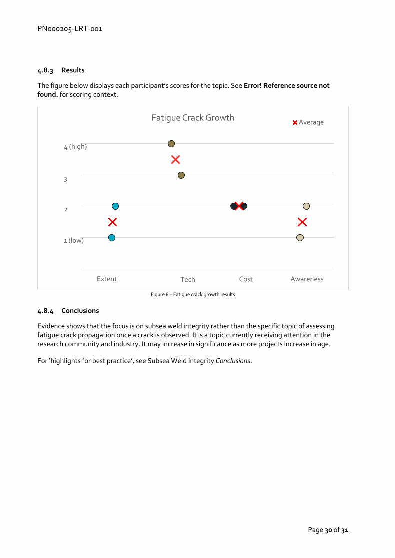
The figure below displays each participant’s scores for the topic. See Error! Reference source not found. for scoring context.
Figure 8 – Fatigue crack growth results
4.8.4 Conclusions
Evidence shows that the focus is on subsea weld integrity rather than the specific topic of assessing fatigue crack propagation once a crack is observed. It is a topic currently receiving attention in the research community and industry. It may increase in significance as more projects increase in age.
For ‘highlights for best practice’, see Subsea Weld Integrity Conclusions.
Fatigue Crack GrowthAverage
4 (high)
3
2
1 (low)
Extent Tech Cost Awareness

PN000205-LRT-001
Page 31 of 31
Contact
ORE Catapult Inovo 121 George Street Glasgow, G1 1RD T +44 (0)333 004 1400 F +44 (0)333 004 1399 ORE Catapult National Renewable Energy Centre Offshore House Albert Street, Blyth Northumberland, NE24 1LZ T +44 (0)1670 359 555 F +44 (0)1670 359 666 [email protected] Ore.catapult.org.uk