Embed Size (px)
Citation preview
DNV GL © 2014 SAFER, SMARTER, GREENER DNV GL © 2014
Offshore wind farm electrical engineering (when considering the operation of array cabling at voltages of 66kV)
1
29th January 2015
Lyndon Greedy / Hans Cleijne
DNV GL © 2014
DNV GL Renewables Advisory (RA)
DNV GL (RA) has worked with almost every major manufacturer. It has led the
market for manufacturer services for many years and is continuously developing
its industry standard turbine design software.
DNV GL has been supporting investors in wind farms for over two decades. The
detailed technical understanding of its experts provides a solid basis for
informing intelligent decisions, regardless of the scale of the project or
investment, or the lifecycle stage.
– Offshore team
– Front End Engineering Design Studies (for numerous offshore wind farms)
– Procurement assistance
2
DNV GL © 2014
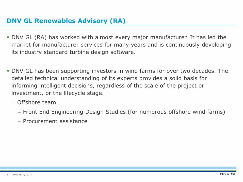
Drivers behind the consideration of higher array system voltages
Wind energy installations are becoming much larger, in terms of:
– Site installed capacity
– Wind turbine rating/capacity
Increase in voltage allows an increase in current carrying capacity
3
11kV ~ 10MVA
2MW
5MW
33kV ~ 35 MVA
7MW
66kV ~ 70 MVA
DNV GL © 2014
Drivers behind the consideration of higher array system voltages
Array cable quantity
– Savings can be achieved if the cable quantity can be reduced.
Offshore substations
– Significant savings can be achieved if there are fewer substations.
Losses
– Annual (and hence lifetime) production losses can be minimised if the collection
and transport of power can be undertaken more efficiently.
4
DNV GL © 2014
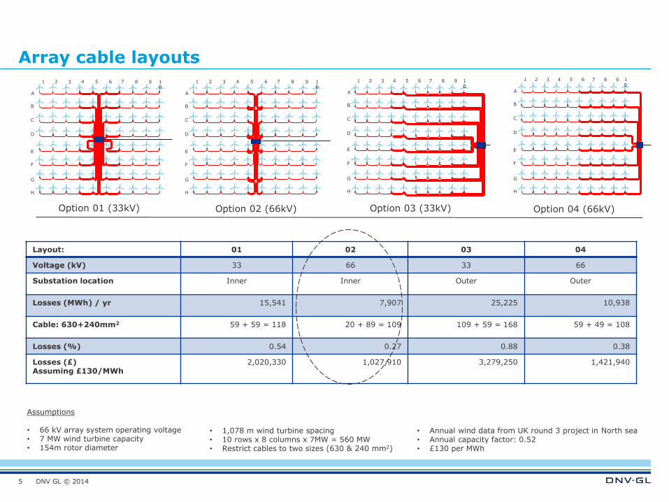
Array cable layouts
5
A
B
C
D
E
F
G
H
1 2 3 4 5 6 7 8 9 10
A
B
C
D
E
F
G
H
1 2 3 4 5 6 7 8 9 10
Option 01 (33kV) Option 02 (66kV)
Layout: 01 02 03 04
Voltage (kV) 33 66 33 66
Substation location Inner Inner Outer Outer
Losses (MWh) / yr 15,541 7,907 25,225 10,938
Cable: 630+240mm2 59 + 59 = 118 20 + 89 = 109 109 + 59 = 168 59 + 49 = 108
Losses (%) 0.54 0.27 0.88 0.38
Losses (£) Assuming £130/MWh
2,020,330 1,027,910 3,279,250 1,421,940
A
B
C
D
E
F
G
H
1 2 3 4 5 6 7 8 9 10
A
B
C
D
E
F
G
H
1 2 3 4 5 6 7 8 9 10
Option 03 (33kV) Option 04 (66kV)
Assumptions • 66 kV array system operating voltage • 7 MW wind turbine capacity • 154m rotor diameter
• 1,078 m wind turbine spacing • 10 rows x 8 columns x 7MW = 560 MW • Restrict cables to two sizes (630 & 240 mm2)
• Annual wind data from UK round 3 project in North sea • Annual capacity factor: 0.52 • £130 per MWh
DNV GL © 2014
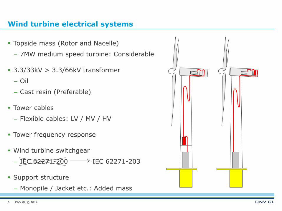
Wind turbine electrical systems
Topside mass (Rotor and Nacelle)
– 7MW medium speed turbine: Considerable
3.3/33kV > 3.3/66kV transformer
– Oil
– Cast resin (Preferable)
Tower cables
– Flexible cables: LV / MV / HV
Tower frequency response
Wind turbine switchgear
– IEC 62271-200 IEC 62271-203
Support structure
– Monopile / Jacket etc.: Added mass
6
DNV GL © 2014 7
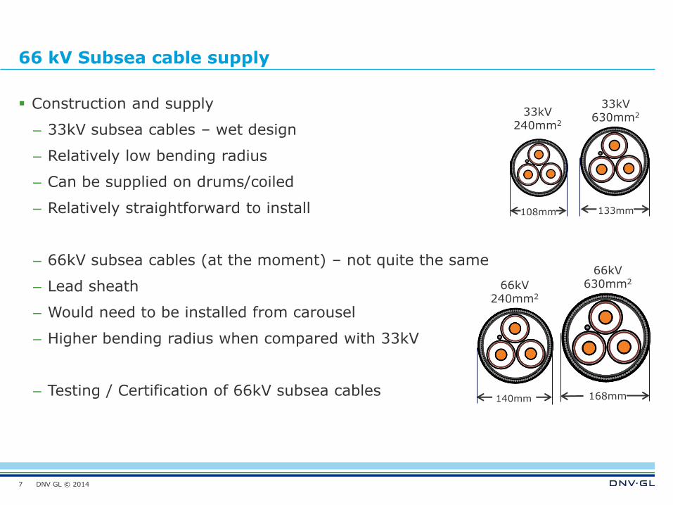
66 kV Subsea cable supply
Construction and supply
– 33kV subsea cables – wet design
– Relatively low bending radius
– Can be supplied on drums/coiled
– Relatively straightforward to install
– 66kV subsea cables (at the moment) – not quite the same
– Lead sheath
– Would need to be installed from carousel
– Higher bending radius when compared with 33kV
– Testing / Certification of 66kV subsea cables
33kV 630mm2
33kV 240mm2
133mm 108mm
66kV 630mm2
168mm
66kV 240mm2
140mm
DNV GL © 2014
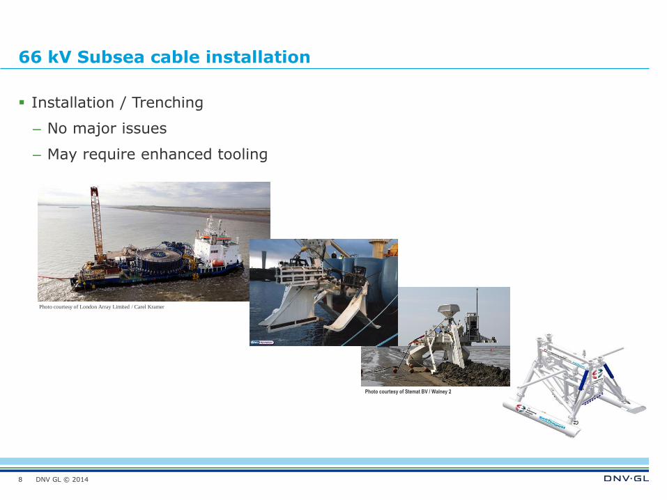
66 kV Subsea cable installation
Installation / Trenching
– No major issues
– May require enhanced tooling
8
Photo courtesy of London Array Limited / Carel Kramer
Photo courtesy of Stemat BV / Walney 2
DNV GL © 2014 9
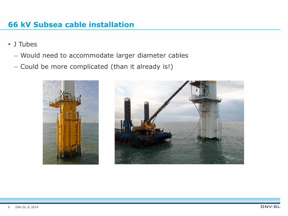
66 kV Subsea cable installation
J Tubes
– Would need to accommodate larger diameter cables
– Could be more complicated (than it already is!)
DNV GL © 2014
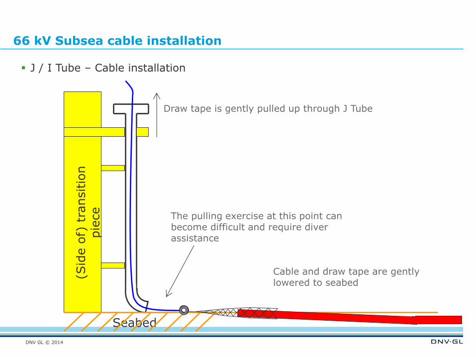
66 kV Subsea cable installation
(Sid
e o
f) t
ransitio
n
pie
ce
Seabed
Cable and draw tape are gently lowered to seabed
Draw tape is gently pulled up through J Tube
The pulling exercise at this point can become difficult and require diver assistance
J / I Tube – Cable installation
DNV GL © 2014
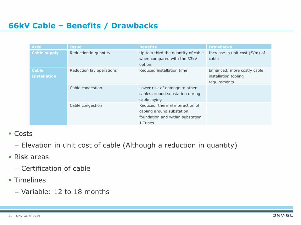
66kV Cable – Benefits / Drawbacks
11
Area Issue Benefits Drawbacks
Cable supply Reduction in quantity Up to a third the quantity of cable
when compared with the 33kV
option.
Increase in unit cost (€/m) of
cable
Cable
Installation
Reduction lay operations Reduced installation time Enhanced, more costly cable
installation tooling
requirements
Cable congestion Lower risk of damage to other
cables around substation during
cable laying
Cable congestion Reduced thermal interaction of
cabling around substation
foundation and within substation
J-Tubes
Costs
– Elevation in unit cost of cable (Although a reduction in quantity)
Risk areas
– Certification of cable
Timelines
– Variable: 12 to 18 months
DNV GL © 2014
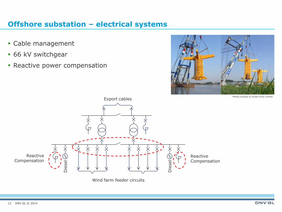
Offshore substation – electrical systems
Cable management
66 kV switchgear
Reactive power compensation
12
Die
sel
Wind farm feeder circuits
Die
sel
Reactive Compensation
Reactive Compensation
Export cables Photos courtesy of London Array Limited
DNV GL © 2014
SAFER, SMARTER, GREENER
www.dnvgl.com
End – thank you for listening
13