Embed Size (px)
Citation preview

University of OsloDepartment of Informatics
OffloadingMultimediaProxies usingNetworkProcessors
Cand. Scient thesisØyvind Hvamstad
Published August 2004

Offloading Multimedia Proxies using Network ProcessorsØyvind Hvamstad
Published August 2004
Abstract
A Multimedia Proxy aims to reduce the client startup latency, network load and server load. Such a proxy maybe subject to many concurrent clients and experience high processing loads due to for example transcoding orprotocol translation. At the same time a high load can be experienced when fetching data from the server. In thisthesis, we will explore how to offload a multimedia streaming proxy by using network processing technology.We design, implement and evaluate a proxy prototype on the IXP1200 network processor. As a proof-of-concept we show that the prototype sucessfully offloads the proxy host in the data-plane, i.e., no data packetsare processed by the host CPU, leaving it free to perform other CPU intensitive tasks. The prototype is able todo application layer forwarding using approximately a thenth of the cycles compared to a traditional architec-ture, where all pakcets are processed by the host CPU.


Table of Contents1. Introduction .........................................................................................................................1
1.1. Motivation and background ............................................................................................11.2. Problem definition .........................................................................................................21.3. Outline of document ......................................................................................................3
I. Background ..........................................................................................................................52. Distributed multimedia systems .........................................................................................7
2.1. General ......................................................................................................................72.1.1. Classification .......................................................................................................7
2.1.1.1. Taxonomy of applications ...............................................................................72.1.1.2. Synchronicity .................................................................................................82.1.1.3. Interaction .....................................................................................................92.1.1.4. Classifying MoD ............................................................................................9
2.2. Requirements .............................................................................................................92.3. MoD access patterns .................................................................................................112.4. Distribution architectures ..........................................................................................112.5. Protocol overview .....................................................................................................13
2.5.1. Real Time Streaming Protocol .............................................................................132.5.2. Real-Time Transport Protocol .............................................................................152.5.3. Session Description Protocol ...............................................................................15
2.6. Summary & challenges .............................................................................................153. Proxies ...........................................................................................................................17
3.1. General ....................................................................................................................173.2. MoD proxy caches ....................................................................................................18
3.2.1. Properties ...........................................................................................................193.2.2. Caching strategies ..............................................................................................20
3.3. Cache architectures ...................................................................................................223.4. Data flow .................................................................................................................23
3.4.1. Copy operations .................................................................................................243.4.2. The Linux network stack .....................................................................................24
3.5. Summary .................................................................................................................254. Network processors ........................................................................................................27
4.1. General ....................................................................................................................274.1.1. NIC evolution ....................................................................................................30
4.2. Intel Internet Exchange Architecture ..........................................................................314.3. Intel IXP1200 network processor ...............................................................................32
4.3.1. The StrongARM core CPU .................................................................................334.3.2. Microengines .....................................................................................................334.3.3. The FBI unit ......................................................................................................354.3.4. Memory interfaces ..............................................................................................35
4.4. IXA application development ....................................................................................364.5. ACE run-time framework ..........................................................................................394.6. Related work ............................................................................................................40
4.6.1. Network layer ....................................................................................................404.6.2. Multimedia streaming .........................................................................................41
4.7. Summary .................................................................................................................41II. Design, implementation and evaluation ...............................................................................43
5. Design and implementation .............................................................................................455.1. Design .....................................................................................................................45
5.1.1. Design goals ......................................................................................................455.1.2. Component overview ..........................................................................................455.1.3. Caching .............................................................................................................465.1.4. Fast forwarding ..................................................................................................475.1.5. Summary ...........................................................................................................47
v

5.2. Implementation ........................................................................................................475.2.1. Limitations and assumptions ...............................................................................475.2.2. Overview ...........................................................................................................485.2.3. The RTSP components .......................................................................................49
5.2.3.1. Conformance issues ......................................................................................515.2.4. Session management ...........................................................................................525.2.5. Cache management .............................................................................................525.2.6. Packet classification ...........................................................................................53
5.2.6.1. Classification rules .......................................................................................535.2.6.2. Forwarding table ..........................................................................................55
5.2.7. RTP forwarding .................................................................................................585.2.8. Summary ...........................................................................................................59
6. Experiments, results and analysis .....................................................................................616.1. Testing environment .................................................................................................616.2. Measurements ..........................................................................................................626.3. Results .....................................................................................................................63
6.3.1. Packet types .......................................................................................................646.3.2. Ingress to egress .................................................................................................646.3.3. Deviation ...........................................................................................................666.3.4. Processing overhead ...........................................................................................686.3.5. Summary of results .............................................................................................69
6.4. The offloading effect ................................................................................................696.5. Prototype performance ..............................................................................................716.6. Extensions ...............................................................................................................72
6.6.1. Caching .............................................................................................................726.6.2. Zero-copy ..........................................................................................................74
6.7. Summary .................................................................................................................757. Conclusions and future work ...........................................................................................77
7.1. Conclusions .............................................................................................................777.2. Future work .............................................................................................................77
References ............................................................................................................................79A. Guide to the attached CD ...................................................................................................83
A.1. Directory structure ......................................................................................................83A.2. Building the source .....................................................................................................83A.3. Running the executables ..............................................................................................83
Offloading Multimedia Proxies
vi

List of Figures2.1. Taxonomy of applications ..................................................................................................82.2. Distribution architectures .................................................................................................122.3. The OSI stack and the Internet protocol stack ....................................................................133.1. Basic proxy architecture ..................................................................................................173.2. Cache architecture ...........................................................................................................223.3. Proxy data flow ...............................................................................................................233.4. Proxy data-path ...............................................................................................................243.5. Linux 2.0.34 network stack ..............................................................................................254.1. Cost vs. performance .......................................................................................................304.2. NPU market shares ..........................................................................................................304.3. Three generations of NICs ...............................................................................................314.4. The Internet Exchange Architecture ..................................................................................324.5. IXP1200 block diagram ...................................................................................................334.6. Command queues ............................................................................................................354.7. ACE processing pipeline ..................................................................................................374.8. Core and microblock components of an ACE processing pipeline .......................................384.9. ACE intercommunication ................................................................................................405.1. Proxy components ...........................................................................................................465.2. ACE layout .....................................................................................................................485.3. RTSP proxy session ........................................................................................................505.4. Packet classification ........................................................................................................535.5. Media Transport Forwarding table ....................................................................................576.1. Test configuration ...........................................................................................................616.2. Experiment 1: Cycle probes for packet reception, forwarding and enqueuing ......................636.3. Experiment 2: Cycle probes for packet forward processing ................................................636.4. Experiment 3: Cycle probe for packet forward processing and enqueuing ...........................636.5. Cycles counted during packet reception, forwarding and enqueuing ....................................656.6. Packets 500 through 700 experiment 1 ..............................................................................666.7. Cycles counted during packet forwarding .........................................................................676.8. Packets 500 through 700 from experiment 2a) ...................................................................676.9. Lazy copy data-structure ..................................................................................................746.10. Zero copy data-path vs. traditional data-path ...................................................................75
vii

viii

List of Tables4.1. Processor hierarchy .........................................................................................................294.2. IXP1200 memory interfaces .............................................................................................366.1. Packet count during session .............................................................................................646.2. Ingress to egress statistics ................................................................................................656.3. Forwarding statistics ........................................................................................................686.4. Experienced overhead .....................................................................................................69
ix

x

List of Examples2.1. Audio data rate and disk usage ...........................................................................................92.2. DVD data rate and disk usage ..........................................................................................102.3. DivX data rate and disk usage ..........................................................................................102.4. Basic RTSP session .........................................................................................................145.1. RTSP request type ...........................................................................................................495.2. RTSP response type ........................................................................................................505.3. Session object .................................................................................................................525.4. Proxy session object ........................................................................................................525.5. Simple branch classification of Ethernet type ....................................................................545.6. IP address validation and transport protocol classification ..................................................555.7. Hash function .................................................................................................................565.8. Incremental checksumming ..............................................................................................586.1. Microblock probes ..........................................................................................................626.2. Pseudo code for packet copy ............................................................................................73
xi

xii

Chapter 1.
Introduction
1.1. Motivation and backgroundPeople are always blaming circumstances for what they are. I don't believe in circum-stances. The people who get on in this world are the people who get up and look forthe circumstances they want and if they can't find them, make them.
—George Bernard Shaw
The Internet is growing at an exponential rate. The increasing availability of low-cost bandwidth forregular users enables new applications that have different requirements than the traditional applica-tions. Streaming audio and video, Voice over IP (VoIP), Peer-to-Peer (P2P) networking, and VirtualPrivate Networks (VPNs) require more bandwidth and computation power than the retrieval of textualdata. The ability to download audio and video content is quite common today. However, continuousplayback of high-quality video often involves downloading large parts of or the whole object beforeviewing it. Streaming is to some extent possible, but usually the quality of such streams is low. In-creased quality will be available as the bandwidth capabilities evolve in the Internet.
Nevertheless, large-scale deployment of Media-on-Demand (MoD) streaming applications in the In-ternet will introduce challenges. The philosophy on which the Internet Protocol (IP) is built, is loosecoupling between heterogeneous networks along with end-to-end responsibility [Clark88]. These ba-sic properties complicate the process of exercising Quality Of Service (QOS). Most, if not all, of theschemes proposed to guarantee some level of QOS are facing problems with scalability, fulfilling theactual level of guarantee or failing to achieve linear deployability [Xiao99].
The lack of a widely spread framework for handling resource reservation restrains the deployability ofMoD. Such applications may require soft real-time guarantees, but will have to run on IP shared me-diums without such support. Network effects such as latency and jitter along with possible congestion,contention and physical failures, will therefore reduce the perceived quality of the media and the sys-tem in general.
To circumvent the lack of QOS support in the Internet, pragmatic methods are used. Over-pro-visioning is commonly used by Internet Service Providers (ISPs). This basically means that extra re-sources are put into the network, enabling it to scale. For example, if the network load exceeds a cer-tain percentage, the links are upgraded so that the level of redundant bandwidth is preserved. Further,if a server is experiencing high loads it is common to upgrade it with better hardware, or to put it in aload-balancing cluster, so that it may continue scaling to the number of concurrent clients.
Another pragmatic method is to reduce the resources needed to serve a client. This may involve re-viewing and optimizing application protocols, improving the performance of servers [Halvorsen01],or the invention of new technologies that allow resources to be used differently. These efforts are lesscommon. However, they are necessary, since over-provisioning cannot solve all problems related toscalability. Also, using over-provisioning as an indefinite measure might prove impractical and ex-pensive.
1

A third way is to distribute the server tasks to an infrastructure of proxies. This has been discussed asa schema to help realize MoD in the Internet. Using proxies is also suggested in distributed gamingresearch. The proxies perform tasks on behalf of the server, e.g., by caching relevant data, shapingand adapting network traffic, etc. Serving clients from the proxy instead of directing them all the wayto the server, reduces network load and latency.
A proxy cache, which sits somewhere between the server and the client, may experience a consider-able amount of network traffic on both its up and down link. The proxy is therefore subject to thesame challenges as the server. It is crucial that the proxy is able to efficiently process informationwithout further adding to the delay. The faster a proxy can process a packet, the better throughput itwill achieve. High throughput will allow the proxy to scale to a potentially high number of concurrentclients.
During the last years, a new generation of Network Interface Cards (NICs) has evolved. These haveonboard Network Processing Units (NPUs), with programmable processing power and hardware spe-cialized for network processing. The aim of NPUs is to provide flexibility and speed so that future andpresent challenges in network development can be met.
This thesis will investigate possible solutions to application specific challenges regarding multimediaproxy nodes by using an NPU, the IXP1200. We will focus on how to offload the proxy and achievinggood throughput.
1.2. Problem definitionMultimedia proxies aim to reduce startup latency, network load and server load. An MoD proxy doesthis mainly by the means of caching. It may, in addition, perform other supplementary tasks to furtherreduce the network load. For example, it may transcode streams on the fly, translate the protocolsused for transport and re-encode a stream to a different format.
As streaming media has relatively high resource demands, and when a proxy must serve many con-current streams at different rates, a careful allocation of resources is needed to support such a load.The load on the proxy increases further, as transcoding, re-encoding and intelligent caching itself maybe highly CPU intensive. We believe that by utilizing the capabilities of NICs with integrated, special-ized NPUs we can offload the data-plane network processing to free resources on the proxy host. Fur-ther, we believe that an NPU can be efficient when processing the network traffic received at an MoDproxy. Two subjects draw our attention:
1. The caching strategies in multimedia take into account that the size of media objects tend to betoo large to be cached in their entirety, unless they are extremely popular. The segments of mediaobjects that are not cached must therefore be fetched from a server and then forwarded throughthe proxy. We specifically believe that the processing of this network traffic can be offloadedonto an NPU.
2. Network processing in a traditional proxy architecture is slow. Operating Systems (OS) providegeneralized abstractions and security features, such as a network stack and memory protectionboundaries. These features require many operations to be performed in order to process a net-work packet in the application layer. We believe that an NPU can be used to optimize the net-work processing needed in an MoD proxy.
To illustrate the feasibility and expediency of an offloaded proxy, we will in this thesis design and im-plement an MoD proxy prototype on a NIC with an Intel IXP1200 chip [Intel01b]. The implementa-tion will basically consist of two parts, an RTSP proxy and an RTP forwarder. The RTP forwarderwill be a proof-of-concept to show application layer forwarding of network traffic. At the same time,the prototype will be the basis of a framework for further work in the area.
1.2. Problem definition
2

1.3. Outline of documentThe rest of this document is divided into two parts; Part I, “Background” will describes the theoreticaland technological foundation upon which this thesis is built. This is done in Chapter 2-4. Part II,“Design, implementation and evaluation” will describe the contributions made in this thesis inChapter 5-7.
Chapter 2, Distributed multimedia systems. This chapter gives an overview of multimedia applica-tions and essential background on distributed multimedia systems.
Chapter 3, Proxies. Here proxies are presented for distributed systems in general and for MoD sys-tems in particular. The properties of an MoD architecture employing proxies are given and differentsystem architectures are presented along with MoD caching strategies.
Chapter 4, Network processors. In this chapter a general introduction to NPUs are given before de-tails about the IXP1200 and the Intel's IXA development platform are presented.
Chapter 5, Design and implementation. This chapter describes the design considerations and theimplementation details of our prototype MoD proxy. It covers the components needed to realize anMoD proxy and the details of how the current implementation works.
Chapter 6, Experiments, results and analysis. In this chapter we will give a precise explanation ofhow we conducted our experiments and what results they produced. Then, the results and contribu-tions are analyzed with respect to our goals and background material.
Chapter 7, Conclusions and future work. In the final chapter we summarize our work and describein what areas we should focus future efforts.
1.3. Outline of document
3

4

Part I. Background


Chapter 2.
Distributed multimedia systems
An image, a sound, they are one in the same, just one likes to move and one stays thesame.
—Karate
Multimedia allows information to be presented in new ways. It has made its way into regular people'slives and is here to stay. Multimedia distribution across networks is however in its infancy. Severalproblems must be solved before high quality multimedia can be accessible in large scale packetswitched networks. This chapter introduces multimedia. The subjects are: application characteristics,requirements, distribution and protocols.
2.1. GeneralMultimedia is, in simple terms, the combination of two or more media in relative synchronization. Itenables human interaction and presentation of information. Any data consisting of a combination oftext, sound, pictures, animation and video is often regarded as multimedia data. Synchronizing themedia involves preserving their relationship in time. A movie combining the media of video andsound will synchronize the voices of the actors with their facial expressions. Even old silent moviescombine two media, text and motion pictures, though in this case there is no synchronization.
A multimedia system is any combination of computer components that have the ability to present, cre-ate or deliver multimedia data. These components may be networks, operating systems and other soft-ware. It is the availability of resources in these components that determine the perceived quality of themultimedia. If one component fails to achieve the required performance, it becomes the bottleneck ofthe system, and no matter how well the other components perform, the end result is influenced by thiscomponent.
Film is just one real-life application. The range of common multimedia applications also includesvideo conferencing, gaming, learning software, and reference material such as encyclopedias.
2.1.1. ClassificationThe multimedia applications above may be classified using several different characteristics. Schemasare available that classify all applications or some subset of them. They are tools that ease the map-ping of what requirements the application at hand has.
2.1.1.1. Taxonomy of applications
One classification schema, shown in Figure 2.1[Peterson00], regards all applications as either elasticor real-time.
The elastic classes of applications has no time bound for the delivery of data. They are however, usu-
7

1The terms synchronous and asynchronous are used in many research areas within computer science. Such as in programming,I/O systems and in communication.
ally not loss tolerant, i.e., they require reliable data transfer. Applications that fall into this categoryare typically text based chat, file transfers and email. These applications can further be classified asrespectively interactive, interactive bulk and asynchronous. These applications do not depend onwhen the data arrives, as long as it arrives. They could benefit from timely delivery of data, but this isno requirement.
Real-time applications do, as opposed to elastic applications, require timely delivery of data. Thismeans that if the data is not received within some time-frame, it is rendered less usable for the applic-ation, or not usable at all. For example, continuous media playback is affected by variations in deliv-ery of data. A user will experience much of this jitter as low quality, due to skips in the playback. Oth-er applications have heavier demands on timely delivery, such as industrial assembly lines with syn-chronization between robot arms. If a message arrives late to one of the robot arms the system will beout of sync.
Real-time applications can further be classified according to their loss tolerance. The assembly lineapplication is an intolerant application as loss of data is unacceptable and would wreak havoc on theassembly line. The voice playback application however, allows occasional data loss, and is thus a tol-erant application.
Another characteristic of real-time applications is their adaptive properties. The intolerant applicationscan adapt to the rate of data or not adapt at all. Tolerant applications on the other hand may, apart ofbeing non-adaptive, adapt to both rate and delay. Video and sound playback may be adaptive applica-tions. Voice is adaptive to changes in delay, i.e., delay-adaptive. This means that when playing backspeech, the silence between words in a sentence can be shortened or lengthened to some extent,without being noticeable. Many audio encodings can also lower or vary the bit-rate of a recording or astream by removing frequencies that cannot be heard. Video playback has the same characteristics asaudio. The delay between frames can be varied, either by quickening the frame rate or slowing itdown. There are also video encodings that can reduce the bit-rate by reducing the quality of eachframe. Video and audio are therefore both delay-adaptive and rate-adaptive.
Figure 2.1. Taxonomy of applications
2.1.1.2. Synchronicity
Distributed multimedia applications can, in addition to Peterson's taxonomy, be either synchronous orasynchronous1. The distinction is here how the two endpoints communicate. In synchronous commu-nication both parties are using the application simultaneously. Though they may be separated in
2.1.1. Classification
8

space, they must both be present at the same time, e.g., in a video conference, when using VoIP orwhen participating in a real-time game. Asynchronous communication, on the other hand, is indirectand the parties may be separated in both time and space; it allows exchange of information, withoutthe need for every involved user being present. The data is typically stored on a server so that the re-ceiving part may fetch it at a later point in time, e.g., MoD.
2.1.1.3. Interaction
Interaction is a characteristic that further differentiates multimedia applications. In reference material,such as Web pages, it is common to use hyper linking to navigate and switch between different media.Other means of interaction are possible, such as voice control and eye movement. In playback applic-ations interaction, if present, involves navigating back and fourth, pause and stop. Such interactivefeatures are called VCR operations. The number of interactive features, or the level of interaction sep-arates these applications into different classes [Buddhikot98].
2.1.1.4. Classifying MoD
MoD applications, such as News-on-Demand (NoD), Video-on-Demand (VoD) and Learning-on-Demand (LoD), are a set of multimedia streaming applications. MoD is, with respect to the twoclassification schemes described, a real-time, tolerant, adaptive and asynchronous application. Theuser expects continuous playback of the media. This requires timely data delivery, which make MoDa real-time application. It is tolerant to the occasional loss of data, although playback quality will bereduced. Depending on the nature of the encoding, a media stream may also reduce the rate at whichdata is sent. This is rate-adaptive behavior. An MoD application is asynchronous due to the fact thatthe distributor may upload a media file to a server. This makes the media available for several users atany time.
The classification of a multimedia application will, among other things, dictate the requirements ofhow it is handled by a multimedia system.
2.2. RequirementsThe classification of a multimedia application gives a high-level understanding of what is required bya multimedia system. As most multimedia applications are real time applications they have implicitdemands of timely delivery. They usually allow some loss of data and have adaptive properties. Ifthey have interactive characteristics, further demands are put on the system.
Nevertheless, compared to traditional textual data, the digitalized representation of video and soundrequire more storage space and bandwidth, due to higher data rates. This is because the informationneeded to encode light and sound waves in a rich way is a lot more than for example the eight bitsusually needed to represent a common character. More bits are therefore required to store media files.This remains a fact even though compression is widely used. How many bytes it takes to store a me-dia object depends on the desired quality, the chosen encoding algorithm and the playback length.,e.g., see Example 2.1, Example 2.2 and Example 2.3.
Example 2.1. Audio data rate and disk usage
Audio in pulse code modulation coded Compact Disk (CD) quality uses 16 bitsamples at 44.1 kHz with two stereo channels [Steinmetz95]. This gives a bandwidthrequirement of 1.35 Mbps and a storage requirement of 607.50 MB for one hour ofaudio.
The bit-rate of media objects requires large disks, but it also requires that the communication system
2.2. Requirements
9

is able to handle these rates. This includes every component that participate in the communication; theoperating system, the entire network, every router and the server and client application.
Example 2.2. DVD data rate and disk usage
A Digital Versatile Disc (DVD) of the current standard, using the Moving Picture Ex-pert Group (MPEG) codec version 2 has, for video, the maximum video bit rate of9.8. The average video bit rate is about 3.5 Mbps, but this is dependent on length,quality, amount of audio, etc. After system overhead, the maximum rate of combinedelementary streams (audio + video + sub picture) is 10.08 Mbps [Taylor04]. The sizeof a one hour long video is then 1.575 GB using average bit rate.
The continuous and real-time characteristics of films, speech, music and multimedia in general haveother requirements besides storage space and bandwidth. The amount of delay and jitter must be keptas low as possible throughout the system. For example, if any component fails to process video or au-dio data in time, glitches in the presentation will be the result. The viewer might as a consequencegive up or gradually lose interest. Further, if a video is to be experienced as flawless, there can be nomore than ±80 ms of skew in lip synchronization. Even higher demands on jitter occurrence arepresent when two stereo audio streams are played back. A person will detect ±11 µs in this setting, sohardly any jitter at all will ruin the playback [Steinmetz95].
Example 2.3. DivX data rate and disk usage
DivX is a codec derived from the MPEG-4 standard. It has become a very popular co-dec for exchanging movies over the Internet [Zimmerman03]. DivX is able to reducethe size of an existing MPEG-2 encoded file 6.5 times, e.g., the required playbackbandwidth drops from 5.6 Mbps to 870 Kbps. The disk usage is reduced from 423MB to 63.8 MB. A one hour long video at 870 Kbps requires 393 MB worth of stor-age.
A real-time system guarantees that deadlines are met while playing back multimedia or other contentwith real-time requirements. Such systems guarantee QoS. QoS is an abstract term that can be used onmany levels. In general, it can be defined in two parts:
1. A set of qualitative and/or quantitative attributes that specify the requirements of an application.
2. A mechanism that ensures that the specified requirements are met by a system running the ap-plication.
A user may typically specify a high abstraction of what quality he/she wishes to receive. For example,low, medium or high quality. On a lower level this specification is translated to a more fine-grainedset of quantitative attributes, so the system may decide if it is able to meet the requirement or not, e.g.,bandwidth, startup latency, jitter and correctness. In a real-time system, the system grants access andthen ensures that the requirements are met, if it is able to satisfy them at the time. QoS is thereforealso regarded as a contract between the user and the system. The user specifies what he or she wants,and the system provides it. However, real-time systems are rare, and no such support is available inthe Internet, unless dedicated resources are set up. However a QoS agreement or contract needs notregard hard deadlines, or require reserved resources. A QoS contract may simply be that certain ap-plications are prioritized. This basically means that throughout the system, applications are handledaccording to their priority. For example, events, actions and messages from a high prioritized applica-
2.2. Requirements
10

tion will be handled by the system before those with a lower priority. Thus, the QoS contract is met ifthe priority scheme works. In the Internet this contract is best-effort, i.e., you get what is available, butwithout any guarantees.
Multimedia systems will need QoS mechanisms to fully support the requirements of multimedia ap-plications. Since such support is inexistent in the core of packet switched networks, other measureshave to be considered to improve a multimedia system's ability to provide satisfactory quality whenstreaming media.
To lower the bandwidth requirement in a system, the data-rate of video streams may be adapted. Thisfurther allows heterogeneous networks with different bandwidth capabilities to receive streams of dif-ferent data-rates. When adapting to jitter, certain codeces, such as MPEG, allow for parts in the videoto be discarded. Also, to reduce the effect of jitter, playback buffers are used at the client side so thatjitter from the network is masked away. However, this fails if a packet arrives after the playback buf-fer is empty.
2.3. MoD access patternsRequests for media objects tend to have certain characteristics. The frequency of access is said to fol-low the Zipf distribution [Sitaram00]. This means that only a few of the available objects are reques-ted by the majority of the users. As a rule of thumb 10% of the objects are requested 90% of the time.Compared to other web content this is a clear characteristic of media object access, as web content ofmedium or low popularity usually include 50% of all material accessed [Wang99]. Newly publishedmedia objects tend to be the most popular objects, e.g., the top ten most popular videos in rental shopstend to be the newest ones. The access frequency of an object is often reduced over time.
When requested, media objects are usually consumed from start to end. If they are not fully con-sumed, they are usually canceled at an early stage [Acharya00]. Objects are seldomly accessed by thesame person repeatedly.
The access to media objects tend to be “write-once-read-many”, which means that the content rarelychanges after being published. Users usually only have read-only interaction, much the same as avideo player or music player.
The observed access patterns of media objects may be used to optimize the systems that deliver them.They also have an effect on what architectural choices that are made to build multimedia systems.
2.4. Distribution architecturesA distributed multimedia system can be built with a client, a network and a server [Sitaram00]. Thearchitectural choices of a distributed architecture may have a large impact on how well the systemworks as there are different pros and cons associated with each architecture. There are three main dis-tribution architectures; hierarchical, distributed and hybrid architectures.
The classic architecture is the hierarchical. It is called the client-server architecture and is shown inFigure 2.2 a). This is the model that traditionally has been used in the Internet. It is a simple scheme,where full control is held by the centralized server. The drawbacks of a pure client-server architectureis that the server represents a single point of failure. That is, if the server fails during execution thewhole system breaks down. Another drawback is that the server is a potential bottleneck in the sys-tem, as all requests must be handled by it. If load exceeds the capacity of the server, then the rest ofthe system will suffer equally and the service will be degraded. Further, as the central server's geo-graphical location potentially may be far away from the clients, the latency may be high. This will res-ult in clients having to wait a long time before receiving any response from the server. Also, as longdistances often imply that every packet must be routed through many nodes, each packet's total timein between the server and the client has a higher probability to vary (jitter).
2.3. MoD access patterns
11

2Streaming solutions such as the Darwin Streaming Server [Apple04], Helix DNA Server [Real04a] and KOMSSYS[Griwodz03] all use a hierarchical architecture.
The benefit of the client-server architectures is, as mentioned, that the server has control of the distri-bution of information to the clients. It is easy to administer such a scenario, both when publishing newcontent, charging for use and updating software. The main reason why it is so, is that data does notneed to be replicated. Everything is centralized. Charging for services is easily managed by a central-ized server and it is also simple to manage any state information as it needs not be replicated. Havinga single copy of every accessible object also reduces the impact on the system when an objectchanges.
The opposite of the client-server model is a distributed architecture called the peer-to-peer model, seeFigure 2.2 b). This is a collaborative model where every node is connected to every other node, andthey all have the same amount of control, i.e., they are “peers”. The P2P architecture has the advant-age that it makes use of the resources that are available on the connected nodes. This distribution ofcomputation removes the bottleneck represented by the server in a client-server architecture. The P2Parchitecture does not have a single point of failure, as every node has the same amount of control. Ifsome nodes fail, the rest will still be able to function without them.
The P2P model is more complex than the client-server model, and no simple access control may beimplemented as control is shared by all nodes. This makes charging for the use of services harder. Re-sources will typically be replicated across several nodes for reliability, making consistent updates ofchanges harder. Another issue with the complexity of P2P architectures is the need for a substantialamount of communication control messages between the peers. These messages are used to exchangesynchronization and meta data. This may flood the network and lead to scalability problems.
The hybrid architecture is literally a hybrid of the hierarchical, i.e., client-sever and the distributedmodel, i.e., the P2P model. It incorporates characteristics from both, by for instance having a central-ized meta-data server, while storage is distributed. Many variations can be implemented and these ar-chitectures may remove some of the drawbacks while keeping most benefits of an architecture.
Existing video and audio streaming solutions tend to choose the client-server architecture2. The client-server architecture has also been the preferred architecture for commercial game vendors because ofthe benefits described above, but it is suggested that a hybrid architecture might be better suited[Mauve02], while still preserving the needs of commercial vendors.
Figure 2.2. Distribution architectures
Regardless of the distribution architecture, there are more ways of distributing the packets that flowfrom a server or in between peers. In the Internet there are three ways to do this. Packets may be sentto everybody with broadcast, to a set or a group with multicast or to one receiver with unicast.
Television uses broadcasting networks to distribute their media. This means that everyone that listenson a certain channel, will receive what is on at that particular moment. MoD, however, must be ableto serve a client whenever it requests to view a certain media object. Therefore, broadcasting is a lesssuitable distribution mechanism. Many variations of broadcasting have been created to adapt to an
2.4. Distribution architectures
12

MoD scenario, but have been unable to provide true-MoD, i.e., that a user can request a media objectat any time.
Most applications in the Internet usually use unicast communication. This means that there is onlyone source and one destination participating in the data transfer. If there are more than one receiver,one copy must be sent to each of them. This is a scalability problem as each unique packet sent to thenetwork must be copied to a multiple number of receivers.
To solve this multicast was purposed. Multicast may also be called group-cast, as clients must join agroup in order to receive the information that is sent out. In contrary to unicast, only one packet is sentout from a sender and it propagates the network as one copy. Along the network path, the packets willbe duplicated if there are clients that have joined from different directions. While multicast is suppor-ted by the IP, it is usually blocked by Internet Service Providers (ISPs). This may be because multic-ast makes it hard to account for network usage and it is is vulnerable to Distributed Denial of Service(DDoS) attacks.
2.5. Protocol overviewProtocols define the format and order of messages exchanged between two or more communicatingentities, as well as actions taken on the transmission and reception of messages or other events[Kurose04]. A multimedia streaming system makes extensive use of protocols. Protocols are neededto control interaction, setup and transfer the data. Protocols also exist to retrieve metadata aboutstreaming sessions, e.g., the Session Description Protocol (SDP) [Handley98].
Figure 2.3 shows the Open Systems Interconnect (OSI) model alongside the Internet TCP/IP protocolstack [Socolofsky91]. Multimedia applications may employ the whole range of protocols, dependingon the characteristics of the application.
The protocol pair that is commonly used for streaming is the combination of the Real Time StreamingProtocol (RTSP) [Schulzrinne98] and the Real-time Protocol (RTP) [Schulzrinne96]. Both these arestandards defined by IETF and are widely supported by streaming solutions. In this section, we de-scribe those that are relevant for this thesis.
Figure 2.3. The OSI stack and the Internet protocol stack
2.5.1. Real Time Streaming ProtocolRTSP [Schulzrinne98] is an application-level control protocol for streaming. It resembles and hasoverlapping features with the Hypertext Transfer Protocol (HTTP) version 1.1 [Fielding99].
The main purpose of RTSP is to establish and control streams of continuous media. Usually, the actu-al data-transfer is performed out-of-band using RTP, but RTSP is not bound to any specific transportprotocol. Data may even be interleaved within RTSP messages. To control a session, RTSP maintains
2.5. Protocol overview
13

session state for each stream.
RTSP supports both multicast and unicast streaming. This may be both playback or recording of such,but the standard does not require an implementation to support recording.
To establish and control streams several methods are defined in the standard. Those required(OPTIONS, SETUP, PLAY and TEARDOWN) by an implementation are shown in Example 2.4.
Other methods are defined as well, such as DESCRIBE, PAUSE, ANNOUNCE,GET_PARAMETER, RECORD, REDIRECT and SET_PARAMETER. Not all of these methodschange the state of a RTSP session, only SETUP, PLAY, RECORD, PAUSE and TEARDOWN do.SETUP starts a session and allocates resources for a stream. PLAY and RECORD start data transmis-sion on a stream that has been set up. PAUSE temporarily halts a stream without releasing its re-sources. Finally, TEARDOWN will halt the stream and free the resources allocated by the session.
The first thing that happens when a client initiates a session, is that it sends a SETUP request to theserver. The central part of this request is the transport specification. In Example 2.4, the client tells theserver that it wants to use RTP unicast to transport the data out of band on port 1004. The streamcould also be sent over TCP, interleaved in RTSP messages or to a multicast group. The server replieswith a status message verifying the request of the client. It also adds the server port pair, where it en-ables data to be received. Note that the first number in the client and the server port pair is for data re-trieval and the second is for any control data on the stream. The data port always is even, and that thecontrol port is always odd, and one higher than the data port. The server has now set up a session onits side and the session number can be used to identify subsequent RTSP requests. The PLAY requestfrom the client therefore adds this number to the session header. The client wants to play the wholelength of the stream, so it sends a range header indicating this. The server sends a status message, andthe streaming starts on the channel setup by the transport specification. When the object is playedback, the client sends a TEARDOWN request and the session is removed.
Example 2.4. Basic RTSP session
C->S SETUP rtsp://10.0.0.2:554/ex.mpeg RTSP/1.0CSeq: 1Transport: RTP/AVP;unicast;client_port=1004-1005
S->C RTSP/1.0 200 OKCSeq: 1Session: 8Transport: RTP/AVP;unicast;client_port=1004-1005;server_port=1008-1009
C->S PLAY rtsp://10.0.0.2:554/ex.mpeg RTSP/1.0CSeq: 2Session: 8Range: npt=0-
S->C RTSP/1.0 200 OKCSeq: 2Session: 8Date: 25 Feb 2004 18:07:02 GMT
C->S TEARDOWN rtsp://10.0.0.2:554/ex.mpeg RTSP/1.0CSeq: 3Session: 8
S->C RTSP/1.0 200 OKCSeq: 3
2.5.2. Real-Time Transport
14

2.5.2. Real-Time Transport ProtocolRTP [Schulzrinne96] is the Internet-standard protocol for the transport of real-time data, including au-dio and video. It can be used for media-on-demand as well as interactive services such as Internettelephony, real-time control and distributed simulation. RTP consists of a data part and a control part.The latter is called the RTP Control Protocol (RTCP).
The data part of RTP is a thin protocol providing support for applications with real-time propertiessuch as continuous media, e.g., audio and video, including timing reconstruction, loss detection, se-curity and content identification. It also features negotiation of what encoding to use.
RTCP provides support for real-time conferencing of groups of any size within the Internet. This sup-port includes source identification and support for gateways like audio and video bridges as well asmulticast-to-unicast translators. It offers QoS feedback from receivers to the multicast group as wellas support for the synchronization of different media streams.
While UDP/IP is RTPs initial target networking environment, efforts have been made to make RTPtransport-independent so that it could be used, say, over TCP, Novells IPX protocol or other proto-cols. RTP does not address the issue of resource reservation or QoS control; instead, it relies on re-source reservation protocols such as RSVP.
2.5.3. Session Description ProtocolSDP describes multimedia sessions for the purpose of session announcement, session invitation andother forms of multimedia session initiation.
Session directories assist the advertisement of conference sessions and communicate the relevant con-ference setup information to prospective participants. SDP is designed to convey such information torecipients. SDP is purely a format for session description - it does not incorporate a transport protocol,and is intended to use different transport protocols as appropriate. Example transport protocols forSDP include the Session Announcement Protocol (SAP), Session Initiation Protocol (SIP), RTSP,electronic mail using the MIME extensions, and HTTP.
SDP is intended to be general purpose so that it can be used for other network environments and ap-plications than just multicast session directories. However, it is not intended to support negotiation ofsession content or media encodings.
The SDP communicates the existence of a session and conveys sufficient information to enable parti-cipation in the session. In this thesis we omit the use of this protocol when implementing RTSP. Thesession information is fetched manually.
2.6. Summary & challengesWhen running distributed multimedia applications in the Internet, the main problem is getting timesensitive data to its destination in the appropriate period of time. The challenges are especially de-manding on the server-side and in the network. Streamed data needs a relatively continuous flow ofinformation in order to maintain its integrity. There is no support for this in IP networks, without ded-icating a route for a particular stream.
IP networks work well for streaming if every packet spends the same amount of time reaching theirfellow destination. However, this only applies in a perfect network where no congestion occurs at anyrouters and where all packets follow the same route or a different route with the same latency. Con-gestion is a result of buffering within the router. The router must buffer packets if the capacity of oneoutput is exceeded, i.e., too many of the incoming packets are destined to the same output port or if itexperiences bursts on input ports. Packets must therefore wait in the buffer or they are dropped be-cause the buffer fills up. Packets may also take different routes through IP networks, as routers mayappear or disappear. Combining congestion with alternative routes results in packets arriving at their
2.5.3. Session Description Pro-
15

destination out of order and the time it takes them to reach the destination may vary.
Another challenge is the latency itself. Synchronous streams in opposite directions, e.g., live conver-sation, must be transmitted through the net before the receiving side can reply. This will, if the latencyis high, result in long gaps from when you end a sentence until you receive a reply. Also in asyn-chronous streaming, e.g., MoD, a client might have to wait quite a bit before the stream can start play-back. This start-up delay is further lengthened if the client has to buffer data to alleviate jitter in thenetwork.
Multimedia applications may also occupy a lot of bandwidth. The high bit-rate puts load on the net-work and makes multimedia servers highly I/O centric. On the server-side this represents a scalabilityproblem as resources are bound to one stream for a long period of time.
In the next chapter, we describe a pragmatic solution suggested to improve this situation: the proxy.
Protocol
16

3To be precise, the role of a proxy is twofold. It may retrieve information on behalf of a client or deliver information on behalfof a server.
Chapter 3.
Proxies
Every peer... may make another lord of parliament his proxy, to vote for him in hisabsence.
—Blackstone
Proxies are network nodes in the vicinity of clients, performing tasks on behalf of a server. They tradi-tionally perform caching, to reduce latency for clients, reduce network load and offload servers. Thesenodes also have other uses depending on the context in which they run. For instance in an MoD set-ting, they may perform re-encoding, encryption and adaption of multimedia streams. They may alsohave general features such as access control, re-routing and simple QOS mechanisms.
3.1. GeneralA proxy is someone that acts on the behalf of others. In politics, a proxy can be given the authority tovote on the behalf of someone else. In computer science, the proxy may be a process or an object act-ing on behalf of a server process or a remote object3. Whether the proxy runs as a stand-alone processon a separate host or is embedded in a local process running on the client host, it is located closer tothe client, along the network path, compared to the server process or remote object. This is shown inFigure 3.1. Every remote call the client makes is intercepted by the proxy so that certain operationscan be performed. These operations vary as to which context the proxy runs in.
Figure 3.1. Basic proxy architecture
17

4Proxies are also used in Remote Procedure Calls (RPC) and Inter Process Communication (IPC) though the operations per-formed differs from those in a HTTP proxy. In IPC, the operations mainly consist of marshalling and UN-marshaling the mes-sages that are sent to and received from the network. Proxies are sometimes called stubs in these contexts.
Proxies4 were first introduced as a way for machines behind firewalls to access web content[Wang99]. This was achieved by placing a host machine on the outer rim of the network with accessto the Internet. The observation was made that the users within such firewalled corporate networkswould access much of the same content. By having the proxies cache text and images, the users wouldget faster access to it. The central server running the service would not have to process these requestsand fewer packets would be sent to the outside. Today, it is fairly common for Internet Service Pro-vider (ISP) and Local Area Network (LAN) administrators to deploy proxies to ensure quick responsewhen users load web content, by caching images and text. In HTTP, a client may be configured tosend every request via a proxy towards the server. The main purpose of the proxy is then basically tocache any content the client may want to receive and only re-retrieve it if it has been altered on theserver. The proxy will then be able to serve the cached content on behalf of the server. If additionalcontent is wanted, it will forward such requests to the server, and cache the response before sending itback to the client. An HTTP proxy may also log web activity and block certain content if so desired.The HTTP contains specific fields concerning proxy operations, such as forcing reload or specifyingthat the content cannot be cached due to dynamically changing content.
In MoD, proxies are used in the same way as in web caching. However, larger objects, different ac-cess patterns and application requirements are characteristics that must be considered. These charac-teristics are explained in Section 3.2.
Proxies are also present in distributed gaming research. A Generic Proxy System for NetworkedGames [Mauve02], suggests that a number of interconnected proxies be deployed at the edge of thenetwork to help minimize the drawbacks, but also keep the benefits of a client-server architecture. Theproxies may then perform various actions on behalf of the server and also send messages amongthemselves in order to relieve the server.
Another suggestion for distributed games [Bauer02] is to use network aware booster boxes. “Boosterboxes acquire network awareness by monitoring traffic, measuring network parameters such as delay,by participating in routing exchanges, or by acting as an application-layer proxy server. Each boosterbox serves a number of clients in its network vicinity and performs caching, filtering, forwarding andredirecting of game events in a game-specific way.”
3.2. MoD proxy cachesAs with HTTP proxies, the MoD proxy's prime operation is to cache objects. However, other applica-tion specific considerations will have to be made in MoD proxy caches than in HTTP proxy imple-mentations. The prime difference is how objects are cached and how they are replaced. MoD proxieshave other application specific uses besides caching. They may perform dynamic transcoding, i.e.,change the bit-rate at which a stream is sent. They may also support changing the encoding on the flyas well as transport protocol translation, i.e., using UDP in a Wide-area network and TCP in a accessnetwork [Griwodz04]. It is therefore hard to use one single proxy implementation to handle both clas-sic web objects and media objects.
Two primary observations motivate the caching of media files in an MoD system. First, an applicationneeds to play back large amounts of data with timely delivery. The continuous media makes the ap-plication sensitive to jitter. To reduce this, the client usually buffers a certain amount of data beforestarting playback. This means that media playback cannot be started until this buffer is filled up. Asmentioned in Section 2.4, the distance from client to server also is a variable that regulates latency. Aproxy cache can alleviate this startup-latency by being deployed in the vicinity of the client. Mediafiles also consume a lot of bandwidth due to their high bit-rate. An early cache hit would therefore re-duce the load on the core of the network.
3.2. MoD proxy caches
18

5There are several categories of transparency such as, access, location, concurrency, replication, failure, mobility, performance -and scaling transparency [Coulouris01].
Secondly, media objects in MoD seldom change, and the “write-once-read-many” pattern is a strongargument for caching these objects in contrast to regular web-objects. There is therefore a low admin-istrative overhead to keep caches up to date. The main problem when caching media files is the stor-age requirement, see Example 2.2. It is impossible to cache the immense amounts data that a collec-tion of media files represent entirely in the memory of a host. It is even hard to cache all available me-dia objects on disk. The Zipf distribution [Sitaram00], however, indicates that a good cache hit pro-gnosis is to cache the 10% most popular films. The hard part is then to know what films are the mostpopular. Many caching strategies exist to deal with the problem of huge media objects. The solution isto partition an object and only cache parts of it. Examples of such algorithms follow in Section 3.2.2.
An MoD system must support the heterogeneity in the Internet. Proxies have to accommodate the re-quirements of different clients with respect to streaming rates and encoding formats. In commercialstreaming systems, this has been solved by replicating objects at different rates and formats. This ap-proach has prohibitively high demands on storage and bandwidth. To avoid this, proxies may performon-demand transcoding of the streams. The intensive computation overhead of transcoding howeverprevents a proxy from supporting a large client population [Liu03].
Bommaiah et al [Bommaiah00] design and implement a proxy using the Internet-standard protocolsRTSP and RTP. They use their prototype to show the performance gains by inserting proxies in astreaming environment. Their results, using a single proxy, show that by caching the 50 first secondsof a 1 minute media object, they are able to reduce network and server loads by 75%. They also showa 50% improvement in startup latency, by streaming the first three seconds ten times faster than thestreaming rate.
Another proxy scheme presented by Acharya and Smith [Acharya00], called MiddleMan looked at thecaching of movies within a campus LAN. While having proxies cooperate when caching objects, theyachieved a high aggregate storage space. Their proxies cooperate through a coordinator process thatheld information about where elements were located. They found that the effective bandwidth of theirentire streaming system increased by a factor between three and ten.
3.2.1. PropertiesTo serve their purpose, proxy cache systems should fulfill certain qualities. A number of these are dis-cussed for Web caching[Wang99] and include fast access, robustness, transparency, scalability, effi-ciency, adaptability, stability, load balancing, dealing with heterogeneity and simplicity. These prop-erties also, as described below, apply to MoD proxy cache system.
• Responsiveness: Users expect applications to respond quickly to commands. If not, they wouldgrow inpatient and maybe stop using the application. This property is important in an MoD cache.In a distributed system without real-time support, a multimedia player uses jitter avoidance buffer-ing to “ensure” continuous playback. The startup latency will therefore to a higher extent be no-ticeable to a user compared to streaming a text document. So, a replica of the data with shortertransfer time to the client, would increase the responsiveness of the application, in respect to bothstartup latency and interaction latency.
• Robustness: How robust a caching system is to failures is a property that for a user is experiencedas availability of the service. Having a single point of failure in an MoD caching schema shouldbe avoided. If one proxy crashes, the system should not be rendered inaccessible to clients. Thesystem should provide fallback mechanisms if one or a few nodes fall out. Proxies may form anoverlay network by being connected to each other in order to provide such robustness.
• Transparency5: A system should appear as a whole and conceal details of the underlying compon-ents from the user. This would imply that inserting a cache in the network should not have implic-ations for the user, other than the improvements of the service. The user should not need to beaware of whether the content is coming from the server or the proxy, nor of how the possible per-
3.2.1. Properties
19

formance gain is achieved.
• Scalability: Scalability is how well a solution to some problem will work when the size of theproblem increases. In a server or proxy system, the increase of resources used should be constantto the increase in usage. A caching scheme must therefore not impose heavy resource demandsdue to changes in density, usage or size of a network. Inserting proxies in a system should not in-crease resource demands. This means that any inter-cache protocols should be lightweight and notadd numerous packets in the network. Also, every proxy must carefully allocate its resources so itmay serve many clients without degrading its performance.
• Efficiency: The efficiency of a system is dependent on the throughput of it. The time spent by pro-cessing or communicating in an MoD caching system should therefore impose a minimal additionto delay on a stream. MoD cache should process as close to link speeds as possible and send fewcontrol packets into the net to achieve this. This is closely related to scalability.
• Adaptability: Environmental changes often mean that behavior must be altered as well. A cacheshould be able to adapt to changes in access patterns and proxy placement. It should either beaware of architectural changes or be configurable to adapt to such changes. It should also be ableto adapt to changes in network load, by altering the data-rate in an MoD stream.
• Load Balancing: This property means to distribute the computation and network load. A cachingscheme should avoid hot-spotting certain parts of a system. It should have mechanisms to distrib-ute load on the network as well as the server.
• Heterogeneity: The Internet is built up using a collection of different computer and network tech-nologies. This heterogeneity is challenging in many areas, and must be considered when designingdistributed systems. A caching scheme must be able to handle the differences in the link -and net-work layers. MoD caches must in particular be able to deal with different formats for representingmedia. Such formats are MPEG-2, AVI, WMA, etc. Also an MoD proxy should be able to deliverdifferent quality streams depending on the clients requirements.
• Simplicity: Keeping the scheme simple is important in order to easily implement and deploy it inan already existing system.
These properties have implications on the design of a proxy system because they dictate the goals ofsuch a design. If a design holds efficiency as a prime concern, then adaption and transparency may geta lower priority. However, efficiency may also imply that the system should be simplistic. Whetherthe properties converge or diverge they impose tradeoffs in a design. There are other possible proper-ties in such a system as well, security being one and extendibility another. These properties are oftenin conflict with scalability and efficiency, as they require resources and time consuming processing.
The properties above applies both to the internals of a proxy host and the surrounding system. Theconsiderations are different if the proxy must cooperate with other proxies than if it is a stand-aloneproxy. A design should not restrict itself, but allow extension so that the adaptability of the proxy tothe surroundings can be met.
3.2.2. Caching strategiesA well known fact is that the optimal way to perform caching is to always have the object that will beaccessed next ready in the cache. Also, when the cache is full, the objects best to replace are the onesthat will not be accessed for the longest time. If a caching scheme could predict this perfectly a perfectcache hit rate would be achieved. However, predicting the future is as impossible in computer scienceas in life. Caching algorithms try their best to predict what to place in the cache and what to replacewhen needed, based on typical application access patterns. In MoD, there are numerous such al-gorithms. Liu and Xu [Liu03] divide them into four categories for homogeneous clients, i.e., for cli-ents that have identical requirements on data-rate, etc.:
3.2.2. Caching strategies
20

• Sliding-interval caching caches a sliding interval of a media object to exploit sequential access ofstreaming media. If two consecutive requests for the same object occurs, the first will fetch the ob-ject from the server and incrementally store it in the cache of the proxy. The second request maythen access the cached portion and release it when fetched. If several requests for the same objectarrive close in time, the last request will be the one releasing the object from the cache. This al-gorithm can be very effective in saving network bandwidth and start-up latency when subsequentrequests for the same object happen within close time intervals.
• Prefix caching caches the start of an object, called the prefix [Sen99]. When serving a request theproxy immediately deliverers the prefix to the client and, meanwhile, fetches the rest of the object,called the suffix from the server. When using prefix caching the size of the prefix is chosen basedon available resources and optimization objectives. It can significantly reduce the start-up latencyof a stream, but it does not reduce the network load or server load to the same extent.
• Segment caching is a generalization of prefix-caching. It partitions a media object into a series ofsegments and set different caching values on each segment. Usually, the first few segments areviewed as more important than those at the end, as they may be pre-fetched. However, if the me-dia object is popular enough, it should also be possible to cache the later segments in a stream. Ifthe popularity of an object decreases the proxy may discard large chunks of the object, but it hasthe possibility of leaving the first segments, e.g., the prefix of the object. This algorithm has aboutthe same savings on start-up latency and network load as prefix caching.
• Rate-split caching partitions the data horizontally along the rate axis, instead of vertically alongthe time axis as the previous three algorithms do. The upper part of the data is cached in the proxy.This algorithm is attractive when the data is variable-bit-rate media. In a non-QoS network it im-proves the network load and start-up latency moderately.
The above strategies all implicitly expects the remaining non-cached data to be fetched from the serv-er in order to satisfy homogeneous clients. However, to serve heterogeneity, layered caching is sug-gested. This method of caching requires a layered encoding of the data, i.e., the data is split into sever-al layers: the most significant layer, called the base layer, contains data representing the most import-ant features of the object, while additional layers, called enhancement layers, contain data that refinequality. The higher the layer is from the base, the more fine grained is the quality. Layered cachingusually caches the lower layers, as they are relevant to all clients requesting the object. On cache re-placement a layer is identified based on popularity, and its cached segments are removed from the tailuntil sufficient space is obtained.
A proxy cache also needs a strategy for replacing objects when the cache fills up. Several methods ex-ist to do this. Podlipnig and Böszörmenyi [Podlipnig03] give a survey of such strategies. They classi-fy them as follows:
• Recency-based strategies: These strategies take into account how much time has passed since theobject was last referenced. These strategies are usually variants of the Last Recently Used (LRU)strategy, which simply replaces the object that has been in the cache the longest without any ac-cesses.
• Frequency-based strategies: These strategies take into account how often a object is accessed, i.e.,the frequency of references decides what to remove. These strategies are usually extensions to theLeast Frequently Used (LFU) strategy. Objects that are seldomly accessed are removed.
• Recency/frequency-based strategies: These strategies combine recency and frequency factors tomake caching decisions.
• Function-based strategies: These strategies use a function to calculate the value of an object. Theyuse different weighting factors in the functions to calculate an appropriate value, e.g., age, size,cost of fetching the object, etc.
3.2.2. Caching strategies
21

6In the reference it says that ECT is based on the Inter-Reference Gap (IRG) algorithm, but personal correspondence with theauthor suggests that this is wrong.
• Randomized strategies: These strategies decides what to replace in a randomized way.
In multimedia caching, the access patterns are a vital piece of information in order to make cachingdecisions. A movie that is accessed often can be regarded as popular and should probably remain in acache. The Eternal history, Conditional replacement and Temporal gap size (ECT) [Griwodz00], isloosely based on the LFU strategy6. It accounts for all requests to an element, and stores this informa-tion in an eight entry history per element. Each entry in the history is the gap in time between twoconsecutive hits on a stored element. The ECT strategy does not remove the history of an elementafter it is removed, so elements have an eternal history. It is conditional as all first time elements arecached, but after being removed the history of the element will still exist and is used for future cachedecisions. This strategy shows good simulation results when caching media objects in a large popula-tion system with many movies.
3.3. Cache architecturesAs shown in Figure 3.1 the proxy is an hierarchical extension to the client-server architecture. To real-ize many of the properties in Section 3.2.1, proxy designs usually include the possibility for proxies tointerconnect. When a number of caches are inserted into a network, the probability of an objectalready being cached increases, i.e., a increased hit-probability [Acharya00]. What differentiates theavailable architectures is how information is exchanged between the nodes and how they are laid outin the network.
A Hierarchical architecture, as shown in Figure 3.2 a), divides caching in levels. A request will tra-verse up the hierarchy until the requested content is found, the response will then traverse back downthe hierarchy, leaving a copy of the content at each subsequent level along the path. The drawbacks ofthis architectural scheme its that many replicas of objects are left down through the hierarchy. Alsothe high level caches become key access points that might go down or become bottlenecks. Lastly, anegative effect is that processing delay is added at each level of the hierarchy.
Distributed architectures or cooperative caching, as shown in Figure 3.2 b), only operate with onelevel of caches. Theses caches distribute meta-information on where to fetch cache misses. The distri-bution of the meta-information may be hierarchical, but fetching a cached object is only done withinthe same level. This model may experience high connection times and high bandwidth usage whenused in large scale. Also, as with P2P, administrative issues exist.
Figure 3.2. Cache architecture
3.3. Cache architectures
22
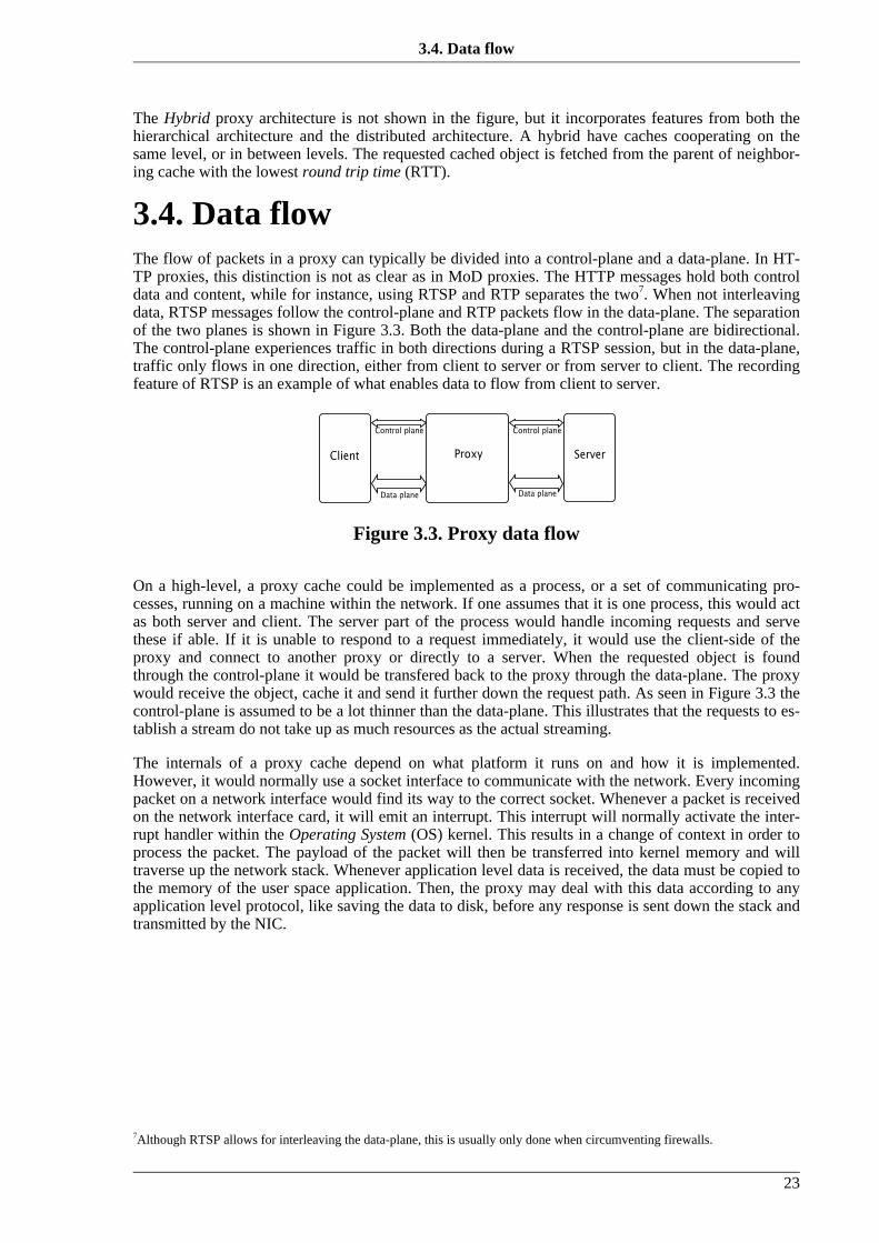
7Although RTSP allows for interleaving the data-plane, this is usually only done when circumventing firewalls.
The Hybrid proxy architecture is not shown in the figure, but it incorporates features from both thehierarchical architecture and the distributed architecture. A hybrid have caches cooperating on thesame level, or in between levels. The requested cached object is fetched from the parent of neighbor-ing cache with the lowest round trip time (RTT).
3.4. Data flowThe flow of packets in a proxy can typically be divided into a control-plane and a data-plane. In HT-TP proxies, this distinction is not as clear as in MoD proxies. The HTTP messages hold both controldata and content, while for instance, using RTSP and RTP separates the two7. When not interleavingdata, RTSP messages follow the control-plane and RTP packets flow in the data-plane. The separationof the two planes is shown in Figure 3.3. Both the data-plane and the control-plane are bidirectional.The control-plane experiences traffic in both directions during a RTSP session, but in the data-plane,traffic only flows in one direction, either from client to server or from server to client. The recordingfeature of RTSP is an example of what enables data to flow from client to server.
Figure 3.3. Proxy data flow
On a high-level, a proxy cache could be implemented as a process, or a set of communicating pro-cesses, running on a machine within the network. If one assumes that it is one process, this would actas both server and client. The server part of the process would handle incoming requests and servethese if able. If it is unable to respond to a request immediately, it would use the client-side of theproxy and connect to another proxy or directly to a server. When the requested object is foundthrough the control-plane it would be transfered back to the proxy through the data-plane. The proxywould receive the object, cache it and send it further down the request path. As seen in Figure 3.3 thecontrol-plane is assumed to be a lot thinner than the data-plane. This illustrates that the requests to es-tablish a stream do not take up as much resources as the actual streaming.
The internals of a proxy cache depend on what platform it runs on and how it is implemented.However, it would normally use a socket interface to communicate with the network. Every incomingpacket on a network interface would find its way to the correct socket. Whenever a packet is receivedon the network interface card, it will emit an interrupt. This interrupt will normally activate the inter-rupt handler within the Operating System (OS) kernel. This results in a change of context in order toprocess the packet. The payload of the packet will then be transferred into kernel memory and willtraverse up the network stack. Whenever application level data is received, the data must be copied tothe memory of the user space application. Then, the proxy may deal with this data according to anyapplication level protocol, like saving the data to disk, before any response is sent down the stack andtransmitted by the NIC.
3.4. Data flow
23

Figure 3.4. Proxy data-path
The data-flow is illustrated in Figure 3.4. An interrupt and a bus transfer (1) is needed to get the pack-et into kernel memory. While being processed by the network stack, elements in memory will passthrough the cache and the CPU registers (2). Then, when reaching the application, the packet payloadmust be copied to user space memory, and every memory element will be moved by the CPU to theuser space memory location (3). If the application then needs to write data to disk, or send new databack out, additional copying and CPU processing is needed.
3.4.1. Copy operationsAs explained above, every incoming payload of a packet must be copied to the applications memorylocation in user-space through the CPU. Several experiments show that copy operations represents amajor bottleneck in high throughput systems, such as a multimedia server, or proxy. For example in[Halvorsen01] a series of experiments using different copy operations on a NetBSD platform, are de-scribed. When copying data into user-space using the copyout() function a 1024 byte block ofmemory was copied in an average of 0.48 µs, i.e., about 447 cycles with interrupts turned off. Similaroverhead is shown when copying from user space to kernel memory and also internal copying withinkernel memory, regardless of whether interrupts were turned on or off. These tests were performed us-ing an Intel Pentium II Xeon 933 MHz processor with a 256 PC800 RDRAM chip.
3.4.2. The Linux network stackThe Linux network stack [Beck99] is an implementation of the BSD socket interface. Although Linuxprovides support for other protocols, such as AppleTalk and IPX, the most commonly used is theTCP/IP collection of protocols. This includes TCP, UDP and IP. The data link layer focuses on Ether-net, but Linux also support other link layers. For instance, the Serial Line Interface Protocol (SLIP)and the Parallel Line Interface Protocol (PLIP). Figure 3.5 shows how packets traverse the stack fromthe physical interface until it reaches the application through the appropriate socket. The figure usesUDP as the transport protocol, but the same applies to TCP.
In their research, Guo and Zheng analyzed and evaluated the network stack performance of the GNU/Linux 2.0.34 kernel [Guo00]. They concluded that a pair of Linux hosts were able to communicate atnear the max of the capability of a 100 Mbps NIC. The setting in which they ran their tests was withboth hosts having 128 MB of RAM and a Pentium II with a clock-rate of 350 MHz. The hosts ran inmultiuser mode, but only a minimum of processes were started.
3.4.1. Copy operations
24
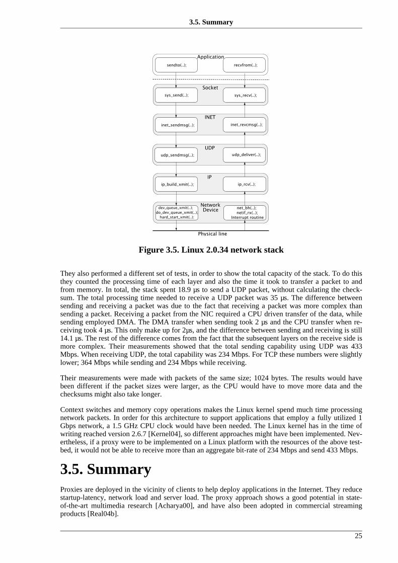
Figure 3.5. Linux 2.0.34 network stack
They also performed a different set of tests, in order to show the total capacity of the stack. To do thisthey counted the processing time of each layer and also the time it took to transfer a packet to andfrom memory. In total, the stack spent 18.9 µs to send a UDP packet, without calculating the check-sum. The total processing time needed to receive a UDP packet was 35 µs. The difference betweensending and receiving a packet was due to the fact that receiving a packet was more complex thansending a packet. Receiving a packet from the NIC required a CPU driven transfer of the data, whilesending employed DMA. The DMA transfer when sending took 2 µs and the CPU transfer when re-ceiving took 4 µs. This only make up for 2µs, and the difference between sending and receiving is still14.1 µs. The rest of the difference comes from the fact that the subsequent layers on the receive side ismore complex. Their measurements showed that the total sending capability using UDP was 433Mbps. When receiving UDP, the total capability was 234 Mbps. For TCP these numbers were slightlylower; 364 Mbps while sending and 234 Mbps while receiving.
Their measurements were made with packets of the same size; 1024 bytes. The results would havebeen different if the packet sizes were larger, as the CPU would have to move more data and thechecksums might also take longer.
Context switches and memory copy operations makes the Linux kernel spend much time processingnetwork packets. In order for this architecture to support applications that employ a fully utilized 1Gbps network, a 1.5 GHz CPU clock would have been needed. The Linux kernel has in the time ofwriting reached version 2.6.7 [Kernel04], so different approaches might have been implemented. Nev-ertheless, if a proxy were to be implemented on a Linux platform with the resources of the above test-bed, it would not be able to receive more than an aggregate bit-rate of 234 Mbps and send 433 Mbps.
3.5. SummaryProxies are deployed in the vicinity of clients to help deploy applications in the Internet. They reducestartup-latency, network load and server load. The proxy approach shows a good potential in state-of-the-art multimedia research [Acharya00], and have also been adopted in commercial streamingproducts [Real04b].
3.5. Summary
25

However, in a large-scale multimedia system, a proxy might need to handle heterogeneous require-ments, i.e., data transcoding, high aggregate network loads and many concurrent clients. It may alsohave to perform protocol translation, encryption and other tasks. Therefore, it is subject to scalabilityissues, as it needs to be able to process high rates of network traffic with real-time requirements andalso perform CPU insensitive tasks as dynamic transcoding or re-encoding. Also, MoD cachingstrategies mostly cache only some segments of a media object and require that non-cached data is re-trieved from the server.
In order for a multimedia proxy to meet the demands of high data-rates and at the same time be flex-ible enough to perform application layer operations, we suggest that it can make use of NPUs to off-load the data-plane. In the next chapter, we therefore present an overview of the NPU technology wewill use for this purpose.
3.5. Summary
26

Chapter 4.
Network processors
God turns you from one feeling to another and teaches by means of opposites, so thatyou will have two wings to fly, not one
—Mevlana Rumi
Traditional network processing is facing challenges. It must keep up with the increasing bandwidthand new types of network traffic. Every packet flows through several layers of processing and issometimes replicated in memory. Calculating checksums and copying memory blocks add overheadto the time required to finish processing a network packet. These facts have motivated innovationswithin network processing. Hardware accelerated processing helps performance and scalability, but isrestricted to change. An increasing demand for new support in networks has therefore led to a techno-logy that intermingles programmability and hardware acceleration: the Network Processing Unit(NPU).
NPUs have the ability to process network traffic aided by hardware and software. They usually havespecial network-task instruction sets for hardware accelerated programmable units. These units per-form wire speed processing. The NPU also allows for general purpose programming for exceptionalcases and applications.
Following in this chapter is a general overview of NPUs and an in-depth description of the Intel pro-duced IXP1200 processor chip [Intel01b].
4.1. GeneralAn NPU may be defined as a system of interconnected programmable devices performing wire speedprocessing of Protocol Data Units (PDUs). The processing performed can be split into the followingmain functions:
• Classification, which establishes a relationship between a PDU and one or many members of a fi-nite set of classes. A class is an abstraction that can be expressed as an action or as a number. Forexample, related to QoS a class may describe the the absolute requirements of the PDU or a classmay simply be the protocol as protocols are treated differently throughout the system. Classifica-tion is the driver of the other network processing functions as it dictates what to be modified, man-aged or encrypted;
• Modification, which changes the contents of a PDU. By modification we mean PDU header edit-ing and sometimes payload editing. Header editing involves insertion, removal and replacement ofheader fields, and payload editing may involve adaption or re-encoding of the data contained inthe PDU;
• Traffic Management, which shapes PDU traffic. This involves queuing PDUs for transmissionwith potential discarding of PDUs based on a predefined discard policy; and
27

8IntServ and DiffServ are extensively documented on www.faqs.org. IntServ components are described in RFC 2210 through2216 and DiffServ is documented in RFC 2474, 2475, 2597, 2983, 3140, 3246, 3247, 3248, 3260, 3289 and 3290.
• Encryption, which encrypts and decrypts the PDU payload.
Traditionally, core network nodes have been processing the low-end of the network stack, i.e., layers1-3 in Figure 2.3. Apart from physically transmitting packets, tasks within these layers are networklayer routing and data link switching. An end node is therefore responsible for processing the high-end of the stack. As mentioned in Section 1.1, the philosophy of the IP relies on keeping the networkcore as lightweight as possible, and this may be the reason for much of its success. It has been shownthat performing complex processing and keeping much state in the core network will deterioratescalability. An example of this is the QoS architecture Integrated Services (IntServ) which was aban-doned in favor of Differentiated Services (DiffServ)8. The difference between the two illustrates thepoint of keeping the core lightweight. DiffServ relies on complex processing to be done at the bound-ary of the network. The core is simply forwarding packets on what they call a Per Hop Behavior. Thisis a simple classification scheme that decides the priority of the packet. IntServ, on the other handholds unique states for every flow of packets in every network node. This is in IntServ done regard-less of where the node is situated; in the core or at the boundary of the network. Even though DiffServkeeps the core lightweight, it is not widely deployed. This may be due to many factors, but one thingmight be that it requires changes in the network nodes. These changes can be applied linearly and dotherefore not need all nodes to be upgraded at the same time, but if processing functionality is imple-mented in hardware, it may be expensive to extend them to support DiffServ.
In all networks, the processing needs to meet the demands of new classes of network traffic, such asmultimedia and VPN, that are becoming common due to increases in available bandwidth. The tradi-tional general-purpose processor architecture is no longer sufficiently able to scale to such a scenario.Application-Specific Integrated Circuits (ASICs) are commonly used to solve this issue by offloadingthe data-plane processing to dedicated hardware. By providing wider memory buses and faster execu-tion times, they scale well for this purpose. The original processor will only process the control-plane.However, ASICs have a long development cycle and lack the flexibility of re-programmability. Thismeans that whenever a bug is detected or whenever extensions are needed to support new classes oftraffic, ASIC designers must enter another development cycle. Re-implementing a whole hardwarechip is a time-consuming and costly process.
NPUs emerged as an alternative solution to meet the increasing demands of network processing. Tobe an acceptable replacement for ASICs and to meet future demands, NPUs should have certain char-acteristics. Though these can be met using different approaches, they have some general aspects:
• Relatively low cost: The key of NPU design is the combination of flexibility and speed, e.g., pro-grammability and hardware. This is what achieves lower cost compared to ASICs. As NPUs alsotarget the entire network processing field, one device may be used in a wide range of networksolutions while ASICs are specialized and must be tossed away when their functionality becomesobsolete. Money is therefore saved when purchasing an NPU as it may be reused in different net-working contexts by changing software. Also, the number of potential purchasers is larger as thesame device can be used in several areas, and re-usage of software libraries and components lowerthe cost and the “Time-to-Market”.
• Straightforward hardware interface: In order to offer a straightforward hardware interface, stand-ards are necessary. By complying to standards such as Peripheral Component Interconnect (PCI)and Direct Memory Access (DMA), it is easier for OSes to supply means of communication, i.e.,device drivers to NPUs.
• Programmability: Programmability may be supported differently on different NPUs. Douglas E.Comer describes the hierarchy of processing units that are used in network processing [Comer03].As shown in Table 4.1, this ranges from General Purpose Processors (GPPs) to low level physicaltransmitters. The GPPs, the Embedded processors and the I/O processors, i.e., the three upperones, are programmable. Each level in the hierarchy performs and is programmed according to thetasks it is meant for. These tasks are not strict, but a rough outline follows. The GPP typically per-
4.1. General
28

forms overall system control and management, complex protocols and a possible administrativeinterface. The Embedded processor processes the high-layer protocols along with reassembly andtraffic shaping. It also controls the I/O processors and handles exceptions and errors. Finally, theI/O processors basically perform reception and sending along with classification and forwardingof packets.
Table 4.1. Processor hierarchy [Comer03]Level Processor Type Programmable? On
Chip?
8 General purpose CPU yes possibly
7 Embedded processor yes possibly
6 I/O processor yes typically
5 Co-processor no typically
4 Fabric interface no typically
3 Data transfer unit no typically
2 Framer no possibly
1 Physical transmitter no possibly
• Ability to scale to high data and packet rates: Without scaling to high data and packet rates, NPUswill be less liable as an alternative to ASICs. In order to scale, NPU must either have processingunits with high processing rate, handle packets in parallel or have many types of processors in thehierarchy of processing units. The lower level processing units are expected to handle many pack-ets without sending them to the higher levels. The high level processors are expected to handlefew packets. For example, the GPPs handle few packets, while the I/O processors handle many.To make the I/O processors scale, they must, as said, either have a high processing rate or executein parallel. No software control the threads running in parallel on the I/O processors. They areswitched and controlled through hardware. This is referred to as hardware supported parallelism.Parallel execution is often supported through hardware by allowing thread communication mech-anisms, i.e., passing messages in between threads is done by hardware.
Another scalability issue is the memory interfaces and their delay. If the processing units weremade to scale by increasing their processing rate, this would not be successful if they had to blockwhile waiting for a memory request to finish. Types of memory differ in access latency. Compar-ing the two basic Random Access Memory (RAM) types, Static RAM (SRAM) and Dynamic RAM(DRAM) shows this difference. SRAM has a typical latency of 1.5-10 ns, while DRAM has 50-70ns. In addition, the bus transfer speed is critical. This is because every request to memory must betransfered back to the processor that issued the request. Asynchronous memory access may maskthe access and bus latency, but this requires processors to process in parallel.
Figure 4.1 shows where NPUs lie in reference to cost and performance, compared to general purposeand ASIC processing. NPU technology is expected to be cheaper than ASICs, but are more expensivethan a general purpose software solution. Performance wise, it is expected to be slower than ASICs,but faster than pure software processing. Again, this is due to the combination of programmability andhardware. The question-marks denote that how cheap and fast NPUs are is unknown and depend onmodel, vendor, etc. Different designs may perform and scale better, while others may prove to becheaper. These characteristics depend largely on design tradeoffs.
4.1. General
29

9An overview of the available NPUs from Intel can be found here: http://www.intel.com/design/network/products/pro-cessors.htm10 Motorola's NPUs can be found here: http://www.freescale.com/webapp/sps/site/homepage.jsp?nodeId=02VS0l
Figure 4.1. Cost vs. performance [Comer03]
Several vendors, such as Intel9 and Motorola10 design and produce NPUs [Shah01]. While the marketvalue was about $60 million in 2003, it is expected that the NPU market is to out-pace the rest of thesilicon markets for the next 5 years [InStat04]. Figure 4.2 shows the main contenders and their marketshares.
Figure 4.2. NPU market shares [InStat04]
4.1.1. NIC evolutionFigure 4.3 shows a rough overview of how the hardware architecture of NICs has evolved. To illus-trate the differences, three network routers are displayed. Each router has two network interfaces, or“blades” connected to a GPP and other possible router hardware, such as switch fabrics and buses.The reason why a router is used as an example, is because this is one of the most central and relevantapplications for networking, and is also one of the primary applications that NPUs are meant for.
4.1.1. NIC evolution
30

Figure 4.3. Three generations of NICs [Comer03]
Figure 4.3 a) is the traditional software router, where all processing except Media Access Control(MAC) functionality is done by the standard CPU. The chief advantages of a software router is lowcost. The main disadvantage is low processing speed. In a software router, the GPP will quickly be-come the bottleneck, as it has to process the aggregate data-rate of all the interfaces connected to it.The aggregated data-rate is defined to be the sum of the rates at which traffic enters or leaves a sys-tem. For example, if both the interfaces of Figure 4.3 a) is able to handle 100 (Mbps), then the aggreg-ate data-rate that the whole router must handle is 200 Mbps. Therefore the software router is unable toscale well as bandwidth in networks increase, e.g., managing several of the 1-10 Gbps NICs availabletoday.
To remedy this fact, much effort has been put into finding out how to relieve the GPP from having todo all the work. As seen in Figure 4.3 b), more functionality is offloaded into the NIC. These devicesperform classification, checksumming and forwarding in addition to layer one and two functionality.To achieve such complex functionality onboard devices, two approaches are common; Special pur-pose coprocessors (ASICs) and Embedded RISC hardware. Using these approaches are costly, butyields high performance.
Figure 4.3 c) depicts the NPU. It is the third generation of Network Interface Cards (NIC). This evol-utionary process is as the second generation, moving towards decentralization of protocol processingin order to reduce the load on a central CPU. This approach is, however supposed to be flexible, yieldhigh performance and be cheap.
In this thesis we have chosen to make use of the Intel IXP1200 [Intel01b] NPU, which will be de-scribed next.
4.2. Intel® Internet Exchange ArchitectureThe Intel® Internet eXchange Processor 1200 (IXP1200) [Intel01b] chip is a part of the Intel® Inter-net Exchange Architecture (IXA) network processor family. The Intel® IXA summarizes the basiccomponents for network processing [Intel02a]:
4.2. Intel® Internet Exchange
31
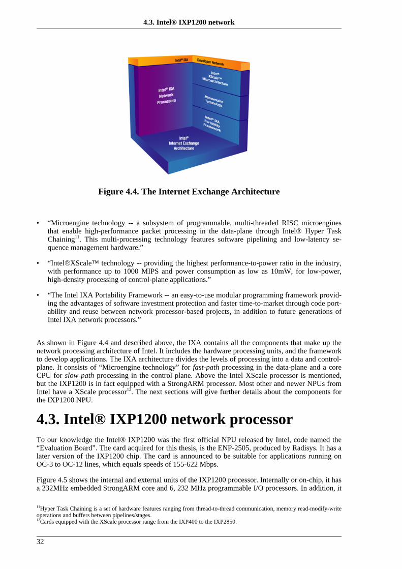
11Hyper Task Chaining is a set of hardware features ranging from thread-to-thread communication, memory read-modify-writeoperations and buffers between pipelines/stages.12Cards equipped with the XScale processor range from the IXP400 to the IXP2850.
Figure 4.4. The Internet Exchange Architecture
• “Microengine technology -- a subsystem of programmable, multi-threaded RISC microenginesthat enable high-performance packet processing in the data-plane through Intel® Hyper TaskChaining11. This multi-processing technology features software pipelining and low-latency se-quence management hardware.”
• “Intel®XScale™ technology -- providing the highest performance-to-power ratio in the industry,with performance up to 1000 MIPS and power consumption as low as 10mW, for low-power,high-density processing of control-plane applications.”
• “The Intel IXA Portability Framework -- an easy-to-use modular programming framework provid-ing the advantages of software investment protection and faster time-to-market through code port-ability and reuse between network processor-based projects, in addition to future generations ofIntel IXA network processors.”
As shown in Figure 4.4 and described above, the IXA contains all the components that make up thenetwork processing architecture of Intel. It includes the hardware processing units, and the frameworkto develop applications. The IXA architecture divides the levels of processing into a data and control-plane. It consists of “Microengine technology” for fast-path processing in the data-plane and a coreCPU for slow-path processing in the control-plane. Above the Intel XScale processor is mentioned,but the IXP1200 is in fact equipped with a StrongARM processor. Most other and newer NPUs fromIntel have a XScale processor12. The next sections will give further details about the components forthe IXP1200 NPU.
4.3. Intel® IXP1200 network processorTo our knowledge the Intel® IXP1200 was the first official NPU released by Intel, code named the“Evaluation Board”. The card acquired for this thesis, is the ENP-2505, produced by Radisys. It has alater version of the IXP1200 chip. The card is announced to be suitable for applications running onOC-3 to OC-12 lines, which equals speeds of 155-622 Mbps.
Figure 4.5 shows the internal and external units of the IXP1200 processor. Internally or on-chip, it hasa 232MHz embedded StrongARM core and 6, 232 MHz programmable I/O processors. In addition, it
4.3. Intel® IXP1200 network
32

13GNU is a recursive acronym and stands for GNU is Not UNIX.
has other functional units that primarily allow the chip to interface external units. These are the FirstIn First Out (FIFO) Bus Interface (FBI), Synchronous Random Access Memory (SRAM) Interface,Synchronous Dynamic Random Access Memory (SDRAM) Interface and the PCI Bus Interface. Theyare described in more detail below.
Figure 4.5. IXP1200 block diagram
4.3.1. The StrongARM core CPUThe StrongARM core is a general purpose CPU that implements the 32-bit ARM V4 architecture.Known to be used in hand-held devices, it has a tradeoff between computational capabilities andpower consumption. The StrongARM is supported to run the GNU13/Linux kernel [Kernel04] and thereal-time operating system VxWorks [WindRiver04]. Cross-compiler tool chains from the GNU[Gnu04] project also exist in order to create executables for the ARM instruction set.
On the IXP1200 board, the StrongARM governs the initialization of the microengines, and it is alsoused for packet processing and exception handling. How this works is further described inSection 4.4.
4.3.2. MicroenginesIntel® has equipped the IXP1200 with six 32 bit RISC processors. These I/O processors, called Mi-croengines are optimized for fast-path packet processing. Their instruction set is tuned for processingnetwork data. This involves reception, inspection, manipulation and transfer of packets. Together withthe FBI, described later, the microengines establishes the fast path of the IXP1200.
Each microengine has an instruction store of 8192 bytes. Every instruction takes up one long-word(32-bits) of control store space. This allows for a total of 2048 instructions to be stored. Once the mi-croengines are running and the StrongARM has loaded the instruction store, execution starts in a five-stage pipeline. When the pipeline is full, every instruction is completed in an average of one cycle. Ifinstructions block to access memory or other external devices, the pipeline must be flushed, and thenumber of cycles needed per instruction will be higher than one.
The Microengines support what is called Hardware Multi-threading which gives them four programcounters and thus also the ability to run four threads each. In theory, this means that a total of 24threads may run concurrently. Threading is supported in hardware through non-preemptive signals
Architecture
33

that are controlled by a threading arbiter unit. What this means is that in order to change from onethread context to another, the current running thread must yield control of its operations. In contraryto preemptive thread scheduling where a timer will interrupt thread execution, threads in non-preemptive scheduling must be programmed to give up control. One thread may potentially runforever, if so desired. When or if a thread yields, it gives control to the threading arbiter. This unit willswap between threads in a round robin fashion, only activating threads that are ready to run. Thescheduling is round robin because the arbiter keeps track of the ready threads and searches in thread-identifier order to find the next to run.
Switching between threads on the microengines does not require the registers to be flushed tomemory. On most general purpose processors this must be done to ensure that the context is the samewhen the thread is rescheduled. The microengines enables the registers to stay untouched by equallydividing them between each thread. This means that fewer registers are available to each thread, but italso means that low overhead is associated with context switches. The overhead is the same as whenan instruction causes the pipeline to abort the current execution, because the execution pipeline mustbe flushed. The number of cycles needed to perform a switch between one thread to another is aboutthree [Johnson02].
Typically, a thread would yield while waiting for data from a functional unit, e.g., the SDRAM unit.When the functional unit is done, the thread is signaled and put back in ready state and may be sched-uled by the arbiter unit. This allows for asynchronous memory access which is a key differencebetween microengines and general purpose processors.
Synchronization is simpler in non-preemptive scheduling as the programmer just need to assure thathe does not yield while inside a critical section of the code. It is important to remember yielding atsome point though, or else the thread will run forever.
The microengines have three kinds of registers. These include general purpose, SRAM transfer andSDRAM transfer registers:
• General purpose registers (GPRs): Each microengine has 128, 32-bit GPRs. These are split intotwo 64-register banks, the A and the B bank. Any instruction that allows two GPRs as input re-quires that they come from distinct banks; one from the A bank and the other from the B bank.
GPRs may be accessed in thread-local or absolute mode. In thread-local mode, each thread has anunique set of 32 GPRs, 16 in the A bank and 16 in the B bank. For threads to intercommunicate,they may use GPRs in absolute mode, making them accessible to all threads running on the desig-nated microengine.
• SRAM transfer registers: SRAM transfer registers are used to read and write to all functional unitswith the exception of the SDRAM unit. They are used to transfer data to and from the SRAM unit,the IX Bus and the PCI interface.
Each microengine also has 64 SRAM transfer registers. These may, as GPRs, be accessed inthread-local or absolute mode. Each thread has 16 transfer registers at its disposal.
Half of the SRAM transfer registers are write-only and the other half is read-only, i.e., 8 write-only and 8 read-only per thread context. In order to write to SRAM, the microengine must put thedata in a write-only register, and when reading, the data must be put in a read-only register. This isthe primary mechanism for asynchronous memory operations. The transfer registers act as a inter-mediate storage, allowing execution to continue regardless of the data transfer, making is asyn-chronous. The distinction between read-only and write-only registers is transparent for the pro-grammer though, because they share the same names in microcode. Reading from the named re-gister accesses the read-only register and writing to the named register accesses the write-only re-gister.
• SDRAM transfer registers: A microengine has the same number of SDRAM transfer registers as ithas SRAM registers, 64 in total and 16 per microengine thread. These registers are exclusively
processor
34

used to read and write to the SDRAM unit. They have the same separation between read-only andwrite-only registers as SRAM does.
Whenever any of the six microengines issues a request to access any of the functional units, e.g.,SRAM, SDRAM or the FBI, the command is put in a FIFO queue internal to the microengine. Thechip-wide Command Bus Arbiter then chooses what microengine that is to be allowed access to theshared command bus next. After being transferred across the bus, commands are put into a set ofhardware command queues shown in Figure 4.6. There are three different queues, the ordered queue,the priority queue and a set of optimize queues. Unless specified otherwise, all commands are put inthe ordered queue. This way, every command is issued in order. This is useful to ensure that amemory location is not modified out of the expected order. Commands specified to go through thepriority queue, will be issued before any other commands regardless of starvation. Finally, the optim-ize queues can be chosen by software to have hardware rearrange the order of commands to take ad-vantage of physical characteristics. In this way, SRAM requests can be separated in multiple readsand then multiple writes instead of alternating reads and writes. However, caution must be exercisedwhen using this functionality, as hazards can occur, such as reading a value that should have beenwritten first, i.e., read-after-write (RAW) or when writing a value in the wrong order, i.e., write-after-write (WAW).
Figure 4.6. Command queues
4.3.3. The FBI unitThe main purpose of the FBI unit is to provide a high-speed interface for receiving and transmittingpackets. It is, as shown in Figure 4.5, directly connected to the Ix Bus where all network packets enterand leave through the Media Access Controls (MACs). In addition, the FBI unit has several chip-wideControl Status Registers (CSRs), a small on-chip SRAM called Scratchpad memory and a little pro-grammable processor called the Ready Bus Sequencer.
When receiving data, the physical MAC interfaces external to the IXP1200 chip will receive Ethernetframes with a Maximum Transfer Unit (MTU) of 1500 bytes. These frames are then broken into64-byte chunks, called mpackets. The Ready Bus Sequencer will periodically poll the MAC devicesto see if any mpackets are present. Whenever 64 bytes are available, the Receive Ready CSR registersare set. The microengines must then be programmed to poll the CSRs and if a packet is ready, instructthe FBI to pull it into one of the Receive FIFO (RFIFO) queues. Then, the Ethernet frame can be dir-ectly reassembled in SDRAM.
To transmit packets an egress ACE would have to reserve space in one of the Transmit FIFO (TFIFO)queues. Then, it must create a mpacket with data from SDRAM and copy this to the TFIFO. Finally,to allow hardware to send the packet, the code must set the valid flag in a CSR.
4.3.4. Memory interfacesThe IXP1200 provides three different memory interfaces, Scratchpad, SRAM and SDRAM. Theseunits have different limitations in functionality, size and speed as shown in Table 4.2.
4.3.3. The FBI unit
35

Table 4.2. IXP1200 memory interfaces [Johnson02]MemoryInterface
MinimumAddressable
Unit
Size Size(bytesmax)
Approx. Un-loaded
Latency (clks)
Special Operations
Scratchpad 4 1K 4K 12-14 Atomic increment, bit test-and-set, bit test-and-clear
SRAM 4 2M 8M 16-20 CAM lock, bit test-and-set, bittest-and-clear, push-popqueues
SDRAM 8 32M 256M 33-40 Direct path to and from theFBI which allows data to bemoved between the twowithout first going throughone of the processors
• Scratchpad: Scratchpad memory is a low-latency on-chip memory interface to all of the microen-gines. As shown in Table 4.2, the Scratchpad is 1024 long-words (32-bit) in size, this equals 4KB.The Scratchpad is as mentioned, physically located on the FBI unit. It provides atomic bit-test-and-set, bit-test-and-clear and increment operations, as well as random read and write opera-tions. Many accesses to Scratchpad memory should be avoided as the FBI unit is responsible formany tasks. The FBI might become a bottleneck and degrade overall performance if Scratchpad isheavily used. However, the Scratchpad might in some cases be useful to efficiently communicatewith the StrongARM as it has low latency and locking functionality. The atomic increment opera-tion is also useful for counters shared by several threads across many microengines.
• SRAM: The SRAM is an off-chip unit that provides an interface for medium latency memory. Itssize is maximum 2048K long-words, which is a total of 8MB. It has, like Scratchpad memory, bit-test-and-set and bit-test-and-clear operations. In addition, it supports eight Last In First Out(LIFO) linked lists. These can be used as stacks with atomic push and pop operations across mul-tiple threads. It also has a generic synchronization primitive for locking and unlocking memory.Locking can be combined with a read operation, and unlocking can be combined with a write op-eration.
• SDRAM: The SDRAM is also off-chip. The unit does not provide any atomic bit operations, but ithas the unique possibility to move data to and from the FBI, without going through the microen-gines. It has a maximum of 32M quad-words (64-bit), i.e., a total of 256MB of memory. What isspecial about the SDRAM is that it must be addressed one quad-word at the time.
As the latency, bandwidth and hardware supported operations differ depending on the memory inter-face, they are also suited for different usages. Scratchpad, as mentioned is good to use for storing fewbytes that are accessed often or shared by threads. SRAM is also good for sharing somewhat largeramounts of data, e.g., lookup tables. SDRAM is typically where packets are stored, as it has the cap-ability to directly move incoming and outgoing packets to and from the FBI unit.
4.4. IXA application developmentDeveloping applications for the IXA environment is significantly different from general purpose pro-gramming, due to the Microengine architecture. The special instruction set, the threading policy andthe memory interfaces mean that the developer cannot abstract himself from the hardware architec-ture. Another distinction is the need for asynchronous behavior throughout the system. Sequential pro-gramming with blocking I/O requests and blocking intercommunication, will quickly degrade per-formance, due to memory latencies. Therefore, communication between components use asynchron-
4.4. IXA application develop-
36

14Other SDKs exist, e.g., from Radisys, but this is actually just an extension of the original SDK from Intel.15This acronym is sometimes expanded as Action/Classification Engine or even Active Computing Engine.
ous message queues and threads yield when accessing memory.
There are two programming languages available when developing applications for the IXA, the mi-crocode assembly [Intel02b] and the microengine C [Intel02c]. The microcode is plain instructioncoding with some handy preprocessor constructions. For instance, while clauses and inline macros areavailable to ease the development process. Microblocks are low-level with full control of hardwareand fast execution. The microengine C, or Micro C, is on the other hand a high-level C-like language.Micro C is not as fast as microcode, but require less in-depth knowledge of the hardware. Both lan-guages have a set of library functions supplied by Intel, but their support for Micro C is, at the time ofwriting, limited to certain platforms and the library contains less functionality than for microblocks.
Intel supply a Software Development Kit (SDK)14 to aid the development of applications for theIXP1200 platform. The SDK from Intel [Intel01a] contains compilers, libraries, different tools tomanage bootstrapping and deployment and a run-time framework. Their libraries hold functions toease common network processing tasks, such as checksum calculation. Also, they advertise to havebeen designed for portability between different IXP processors as their instruction sets might differslightly.
The Active Computing Element (ACE)15 model is a central abstraction within the IXA Framework. Itis the base of every IXP application using the Intel framework. ACEs can be used to realize pro-cessing element pipelines. Either as a high-level model or as implemented components. Each ACE isa single instance in a processing pipeline. ACEs are interconnected to each other to completepipelines. The pipelines may have several branches, which means that an ACE may have several out-puts. Packet processing is henceforth performed in each ACE. This is illustrated in Figure 4.7. The in-gress ACE receives the packet. The processing ACE may classify and modify before the egress ACEtransfers the packet to the a designated output port.
Figure 4.7. ACE processing pipeline
Figure 4.7 is a simplified model of an ACE pipeline. The model gives no information of how theACEs are realized. The following defines the different types of Intel ACEs:
• Conventional ACE: This type of ACE, also called standard ACE, is not using hardware to acceler-ate its performance but runs solely on the StrongARM.
• Accelerated ACE: An accelerated ACE, also called microACE, employs hardware to accelerate itsperformance. The microACE uses the microengines as means to accelerate themselves. They aresplit into two components: a core and a microblock.
• Library ACE: This kind of ACE usually have a well-defined interface. Other ACEs may use thisinterface. Library ACEs may be both accelerated by hardware or not.
A microACEs is constructed by two components; a core component and a microblock component.Figure 4.8 shows the two tiers and the possible communication paths. The core component of an ACEruns as a user-space process on the StrongARM CPU. It typically administers the microblock, byloading it into the instruction store and by handling runtime exceptions. It may also take part in thepacket processing. The microblock component is running on one or more of the microengines, togeth-er with other microblock components or alone. It performs one or several parts of the networking pro-cessing tasks, e.g., classification or modification.
4.4. IXA application develop-
37

16The implementation done in this thesis has not utilized this tool as of yet. It might be useful later, to find optimizations for oursolution.
Figure 4.8. Core and microblock components of an ACE processing pipeline
To be run, microblocks must be assigned to a microengine. As mentioned, it may occupy the enginealone or share it with other microblocks. The process of deciding what microblock is to reside onwhat microengine is called partitioning. One partition is called a microblock group in the Intel docu-mentation. They may also be replicated across more than one microengine, e.g., the same microblockgroup may be run by more than one microengine.
Partitioning which threads to run on which microengines is a challenge that makes programmingNPUs an art. Kulkarni et al [Kulkarni03] measured that inefficient partitioning could impact thethroughput by more that 30%; a better allocation of components and arbitration of resources can in-crease the throughput by at least 10%. They say: “Partitioning of functionality onto processors andthreads is an important first step towards achieving an implementation that meets the required per-formance metrics. The programmer has to match properties of the application with characteristics ofthe underlying hardware.” This statement further implies that hardware knowledge is imperative in or-der to develop efficient programs for NPUs. They also claim that few tools exist to support simulationof partitioning. The IXA SDK [Intel01a] comes with a workbench that have such a simulator, and it ispossible to verify how threads and microengines interact16. Other challenges presented by Kulkarni etal is for example what the programming effort is to reach a certain performance criteria. For theIXP1200, 32% of their code deals with internal communication, such as bus and memory access,while 63% is calculations.
ACEs can be independently developed and are bound together at run-time, i.e., late binding. What latebinding means in this context is that nothing is known about the neighboring ACEs at compile time,but these targets are resolved when the whole application starts.
The Intel IXA SDK comes with tools that automatically load the microcode images onto the appropri-ate microengines. This configuration tool is largely restricted by the fact that only two microcode im-ages can be loaded, one on the receiving side and one on the transmitting side. The receiving side iswhat Intel calls the ingress and the transmitting side is the egress.
In order for ACEs to communicate with other programs, a mechanism called crosscalls is available forthe Intel IXA SDK. This is a IPC mechanism, that allows core ACEs to export interfaces that may becalled by other applications or core ACEs. Other applications or ACEs may also register to receiveevent notifications. The crosscall mechanism is a handy way to configure ACEs at run-time and toshare state between applications and the underlying ACE framework. Crosscalls are very similar toOMG's CORBA standard [OMG04], but it is in no way compatible with it. The main similarity is thatcrosscalls also use the Interface Definition Language (IDL) to specify the interfaces that ACEs are toexport. The IDL code is handled by a stub and skeleton generator to create the client and server code.
Packet reception in the IXA SDK is performed by a set of microACEs. The realization of a microACEneeds an initialization microblock and a processing microblock and Intel has developed what they callthe Ingress ACE for this purpose. As the IXP1200 card used in our case has four Ethernet interfacesthe Ingress microblock to use is the EthernetIngress. Regardless of what ingress implementation asolution chooses to use, packet reception follows the same pattern.
ment
38

4.5. ACE run-time frameworkAs one of the goals of the IXA application development process is to allow re-usage of code, ACEscan be independently developed. This, as mentioned, requires a run-time where they can be bound to-gether. Also, as microACEs have one component running on the StrongARM and a microblock run-ning on one or several microengines, support for loading the microcode and initializing the ACEsmust be given.
The Intel IXA SDK supplies such a run-time framework for deployment of ACEs. It consists of user-space programs, kernel modules and run-time libraries. The four main components are:
• The Object Management System (OMS) component is a set of user space processes, that allowbinding and resolving names to the underlying system as well as a IPC mechanism called cross-calls. The OMS has three processes: the resolver, the name server and the communications man-ager.
The resolver is used to create ACEs, delete ACEs and bind named targets in an ACE to specificdestinations. This is the binding of input from one ACE to another. This is indicated by the arrowsin Figure 4.7. Basically, this means the resolver sets up the data flow through the core componentsof the IXA application.
The name server manages the correspondence between names and the internal representation of anACE. A programmer may name an ACE and the name server will store the relation between thestring and the handle to the object.
The Communications manager manages the crosscall mechanism the distributed objects use tocommunicate. This allows core ACE components to communicate with regular programs that runon the StrongARM. Say a configuration application or a process that retrieves information fromthe ACE at run-time.
• The Resource Manager is a loadable kernel module that handles communication between the mi-croengines and the StrongARM. It loads software into each microengine at startup and managesthe message queues when messages propagate from the StrongARM component to the microblockcomponent or vice versa. As the microengines and the StrongARM use different addressingschemes the resources manager also provides an API to map between such addresses.
• Operating System Specific Library (OSSL) is a shared library that supports portability. Instead ofusing calls to, for example Linux specific functions, calls are made through the OSSL. It is basic-ally an adapter so that code may run on other operating systems as well.
• The Action Services Library (ASL) is a kernel module. It provides run-time support for core com-ponents such as an event processing loop and network libraries. The library defines an API toprovide entry points to initialize and start the ACEs. It provides finalize primitives to terminateand clean up when execution halts.
Figure 4.9 shows three micro ACEs bound toghether at run-time. Two microblock groups are loadedthrough resource manager API and are the assigned to one microengine each. The core ACEs areloaded on the StrongARM as user processes within the ACE framework, and communication pathsare setup towards the microblocks through the resource manager. The intercomminucation betweenthe core ACEs are are set up by the OMS reslover.
39

Figure 4.9. ACE intercommunication
4.6. Related workEven though the NPU is a relatively new technology, there has already been much research in thefield (see for example www.ixaedu.com/resources). Most of the effort has been looking into how wellNPUs may support router applications (see below). Other application areas are also suggested andtested, such as on-the-fly Video-quality adjustment [Yamada02], active networking [Kind03] and useof NPUs in conjunction with proxies to support distributed gaming [Bauer02]. The research we havereviewed is mostly based on the IXP1200, but some deal with network processors in general, or areapplicable to NPUs in general. In the early work of this thesis, we also reviewed some work done onolder NPUs.
Some research is dedicated to how well a programmer can allocate resources within an NPU for spe-cific applications. I/O engine allocation, also called partition [Kulkarni03] is, as mentioned, a chal-lenge for NPU programmers. Also, comparisons between different hardware architectures withinNPUs is also a subject that is critical to understand in order to choose the right NPU architecture foran application. The different Processing Element Topologies[Gries03] deals with how many stagesprocessing is pipelined in to complete a set of functionality. It is shown that depending on what theprocessing does, different topologies have different effects.
In [Mackenzie03] the four 100 Mbps ports on an IXP1200 NIC was exposed to either the host kernelor to user level applications by implementing firmware on the IXP1200. They estimate that only 40%of the resources was utilized on the IXP1200 board, and that this enables application specific pro-cessing in addition to their solution.
4.6.1. Network layerRelative to the subjects we have reviewed, a significant amount of research have been made on net-work layer applications, i.e., router applications. Ranging from how well hardware-software routersscale to their aggregate data-rate to how routers may be extended and fit into active networks.
A group of scientists at Princeton have done much work in this area. In [Spalink01], a hardware accel-erated software router was implemented and evaluated using the IXP1200 Evaluation Board. Utilizinga three-level processor hierarchy in their solution, the GPP, the StrongARM and the microengines,they achieved extensibility, a high forwarding rate and robustness. The router could be exposed tonew functionality at any of the three layers, without degrading robustness or forwarding performance.
4.6. Related work
40

This work resulted in an extension to the router architecture, called the Virtual Extensible Router Ar-chitecture (VERA) [Karlin01]. The aims of the architecture is to bridge the gap between new servicesfor IP routers and the underlying hardware. VERA defines three layers to provide the necessary ab-stractions. The upper layer, called the router abstraction, is where extending features can be pluggedinto the system. The lower layer is the hardware abstraction, that hides details about the hardware andfinally a middle layer is a distributed OS that ties the two other tiers together.
VERA was also used in another project [Shalaby02] to make an extensible router for Active Networks(AN). In ANs, packets are not passively forwarded, but code carried in packets can actively influencethe forwarding process in routers. The main addition to VERA in this paper, was how the control-plane was handled in order to support active injection of arbitrary code.
AN is also discussed in [Kind03], where they argue that the performance of secure and manageableAN approaches can be addressed by NPUs. Their prime argument is that injection of code requiressignificant data-plane processing, which suits the design of NPUs. They also offload AN functionalityonto an NPU, and claim that it is done without sacrificing the safety of traditional IP networking.
An example of router functionality loaded onto an NPU is the implementation of a DiffServ edgerouter on the IXP1200 [Lin03]. Here, a set of benchmarks were run to determine bottlenecks in theimplementation. It was shown, that under different conditions the implementation would experiencepossible bottlenecks both in SRAM access and in microengine performance. To solve these issuesthey suggested changes to the hardware, such as faster SRAM units.
Research efforts have been made on how to share load between several NPUs distributed within arouter [Kencl02]. This was done using a feedback control mechanism to prevent processor overloadand adaptive scheduling of the incoming traffic. Another area traffic policing for servers and routersin order to stop misbehaving clients and Distributed Denial of Service (DDoS) Attacks [Mirkoviç02].
4.6.2. Multimedia streamingAs the subject of this thesis is offloading multimedia proxies, it was interesting to find other work inthis area. To our knowledge no work exists, that overlap with ours, but suggestions are made thatNPUs can be used to offload multimedia applications in VoD servers, high-definition video clientsand in multimedia editors. For example, an NPU was used to support a high-definition video client[Fiuczynski98]. This solution had the NIC process video data and transfer it directly into a framebuf-fer device. This way the host was offloaded while the client viewed the data.
Also, NPUs have been evaluated in a on-the-fly adaption of MPEG-2 streaming scenario [Yamada02].By implementing a low-pass-filter on an IXP1200 chip, utilizing the microengines and theStrongARM to do the work, Yamada et al showed that when using all 6 microengines for video filter-ing, they were able to process streams up to a rate of 1.35 Mbps.
4.7. SummaryIn this chapter we have given an introduction to NPU technology and a specifically described detailsabout the IXP1200 NPU. NPUs provide the network programmer with a mix of speed and flexibility.To program the IXP1200 knowledge about hardware is needed and tasks must be carefully allocatedto the appropriate processing unit.
Next in this thesis, we will make use of the IXP1200 chip to design, implement and evaluate a proto-type that aim to offload the control and the data forwarding of an MoD proxy.
4.6.2. Multimedia streaming
41

42

Part II. Design, implementation andevaluation

Chapter 5.
Design and implementation
Everything should be made as simple as possible, but not simpler.—Albert Einstein
Power at its best is love implementing the demands of justice. Justice at its best islove correcting everything that stands against love.
—Dr. Martin Luther King Jr.
5.1. DesignWhen designing an MoD Proxy, the things to consider are the properties of caching, the architecturethe proxy is to be inserted into, and the caching strategy to use. This also includes the replacement al-gorithm of the cache. The data path through the proxy must also be considered, so that good through-put can be achieved. Other considerations have to be made if the proxy is to perform other tasks forthe server or the client. Possible tasks include re-encoding, adapting or encrypting the stream passingthrough the proxy. Access control, overlay-multicast, traffic engineering and protocol translation arealso mechanisms that may be performed by a proxy. Also, when designing a proxy for a platform, thecharacteristics of that specific platform must be considered. This chapter will describe the designchoices of our prototype.
5.1.1. Design goalsThe goal of this design is to enable the implementation of our prototype for our specific architecture,namely the Intel IXP1200 NPU [Intel01b]. We will also attempt to design the proxy in a manner sothat it easily may be used for testing and comparison on other platforms. The design is founded on acomponent view of the proxy. This should give us the choice of how tightly bound every componentwill be in the resulting system. What this means, is that no hard separation of the components are re-quired. Also, components can be used to extend the design at a later point in time. In this way, thedesign will provide a framework for further work. The design should enable taking advantage of theproperties that the IXP1200 has, i.e., it should enable us to utilize the processor hierarchy. Thus, thefunctionality can be split up and be run on the appropriate processing unit, ranging from the host CPUdown to the microengines of the IXP1200. The design should lastly allow the appropriate communica-tion channels between the separated layers.
5.1.2. Component overviewTo utilize the processor hierarchy of the IXP1200, we have split the proxy into several logical com-ponents. These, as shown in Figure 5.1, are separated in two main layers; the control-plane and thedata-plane. This decision is founded on the observation that the MoD proxy employing RTSP/RTPhas a distinct control-plane and data-plane (see Section 3.4). The separation of the two layers is
45

needed for other reasons as well. The data-plane in an MoD schema utilizes RTP over UDP, so itmust either be embedded asynchronously in the RTSP component, or it must run as an independentthread or process. This makes the design valid on a regular platform as well as on the IXP1200. Theseparation is even more distinct on the IXP1200, as we will run the RTP components bound togetherin an ACE to make use of the processor hierarchy. Not shown in the figure is the classifier compon-ent. This is a special component needed to direct packets that are received by the microengines. Thefunctionality of the classifier component would be handled by the network stack on a more conven-tional platform, such as Linux or BSD.
The figure also shows a caching manager and a session manager component. These components arebasically components that add MoD functionality. The session manager is needed to store sessionsand communicate this information between the control-plane and the data-plane. The cache managercomponent will be storing media that flows through the data-plane. A signaling mechanism must alsobe present between the cache manager and the session manager to know what data to cache and not. Itshould also handle cache replacement.
There are several other components that would fit into the design of an MoD proxy. Re-encoding, ad-aption or encryption components are possible relevant extensions. What characterizes these compon-ents is that they require significant processing power. Implementing them onboard the IXP1200would probably deplete the resources available to process other traffic at high speeds, even though itis shown that the IXP1200 was able to adapt a video stream using the StrongARM and the microen-gines [Yamada02]. An option is to allow this kind of functionality to be allocated to the host CPU asit usually has more cycles to spare, if successfully offloaded by an IXP card.
Figure 5.1. Proxy components
In addition to the control-plane and the data-plane, there is also a management-plane. This plane con-sists of the Intel configuration tools and our own management tool. What the management plane doesis basically conveying the information needed at startup for the other planes.
5.1.3. CachingThe caching is designed to be independent of any replacement algorithms or caching strategies. Thedesign is more concerned with enabling an implementation to efficiently transfer the data that will becached. This means that the design is not focusing on the cache mechanisms, but on the ability to effi-ciently cache data on the fly or quickly fetch data from the cache.
The caching component is partly in the control-plane and partly in the data-plane as shown in Fig-ure 5.1. The RTSP server will do lookups through the cache control to see if requests can be servedentirely or partially from the cache. Also, the cache control must be able to signal the session manager
5.1.3. Caching
46

about when to start caching or stop caching of the data transfered in the session. Any replacement lo-gics and strategy logics will be in the cache control. This logic could be embedded in pluggable sub-components so that caching strategies can easily be changed.
The data-plane part of the cache component is where data flowing through a stream will be written tothe cache storage and at the same time forwarded to a client. Achieving good throughput is important;unnecessary delay on the stream must be avoided and resource usage must be kept low within theproxy. Stream data that is not going to be cached will simply be fast forwarded or buffered if it hasbeen prefetched.
5.1.4. Fast forwardingWhenever the cache control is satisfied, i.e., it has cached the amount of data that is required by thecache strategy (see Section 3.2.2), the remaining data in the stream will be forwarded to the clientwithout being sent to the cache storage. This also applies when the cache control has decided not tostore any data elements of a stream. As illustrated on Figure 5.1, the cache is bypassed in these casesand the packet is forwarded directly.
5.1.5. SummaryWe have described a basic MoD proxy design. It includes the components needed to give the proxythe most common functionality. Next, we will describe how we have implemented these componentsin our prototype.
5.2. ImplementationThe prototype implements all the components of the design described in the previous chapter, with theexception of the caching component. This includes the classifier, the RTP and RTSP componentsalong with the session manager. The prototype is implemented as a set of inter-operating componentsusing the Intel IXA framework and the embedded Linux operating system.
The design is realized by developing an RTSP proxy and a Classifier/RTP-forwarder ACE. These ex-ecutables are then assembled together with Intel ACEs to realize the prototype.
5.2.1. Limitations and assumptionsThe implementation of the prototype is largely limited by the time frame of the project. The prototypeimplements the most basic functionality so that results can be collected, and so that the proof-of-concept can be shown. However, the prototype is far from being a fully fledged system, and wehave made the following limitations and assumptions:
• The implementation is limited to deal with performance issues and will focus on using the abilitiesthat NPUs like the IXP1200 have to enhance these properties. In particular, the prototype aims tooffload the proxy host in the forwarding of RTP/UDP packets and thus reduce the networking pro-cessing needed by the proxy host.
• The prototype will neither perform caching, i.e., transfer of data to the host for storage, nor does itimplement cache replacement algorithms, but the proxy is prepared for a cache extension. Cachingobjects is regarded as the prime functionality of an MoD proxy, so we will discuss how it can beimplemented in an efficient manner later (see Section 6.6.1).
• No strong assumptions are made about the caching strategy, but for a system streaming large me-dia objects with high data-rates, it is unlikely that the cache will hold any of the objects in theirentirety. Therefore, strategies like prefix, segment or layered caching are considered as the mostlikely ones (see Section 3.2.2).
5.1.4. Fast forwarding
47

17As explained, the slow path is processing performed by the core ACEs or other programs running on the StrongARM.
• The implementation assumes that only one data source exists. This means that it does not supportany distribution mechanisms to inter-operate with other proxies on their same level, i.e., meta-information distribution between proxies or overlay network routing. It may, however, be part of ahierarchical distribution architecture where the data source assigned to it may be another proxy(see Section 3.3).
• Although the proxy is implemented to support multiple streams in parallel, no tests have beenmade to verify the actual support.
5.2.2. OverviewThe design described in the previous chapter may be realized in different ways. As the components ofthe proxy have different tasks to solve, their respective implementations are based on the characterist-ics of these tasks. The control-plane tasks need relatively more complex processing compared to thedata-plane tasks. Therefore, the RTSP processing is implemented as a regular executable in theStrongARM GNU/Linux environment. The data-plane processing is quite simple, but as the data-ratesare potentially high, it needs to perform well to yield high throughput. The RTP/UDP packet pro-cessing are therefore implemented as an ACE using the Intel IXA framework.
The separation between the control-plane and the data-plane is again shown in Figure 5.2. The figureshows an outline of how the packets will flow through the proxy. Every packet will, after they are re-ceived, be classified. A simplified view of this classification will basically result in one of two pos-sible actions. The packet will, if classified as a TCP packet, be sent to the slow path17 as a potentialRTSP packet.
Figure 5.2. ACE layout
If it is classified as a UDP packet, a lookup will decide if it is a RTP packet that should be further pro-cessed by the microengines, e.g., fast path processing. The Egress ACE will be responsible for mov-ing packets to the physical layer. The classification process is fully explained in Section 5.2.6.
As explained in Section 4.4, the IXA platform makes use of ACEs to create processing pipelines. Fig-ure 5.2 also shows this concept with regards to our prototype. The figure is not entirely correct in this
5.2.2. Overview
48

sense, as the Intel Ingress ACE only controls the input/output interfaces, by configuring their settings,e.g., MAC and IP addresses. The Ingress ACE is thus not involved in the processing of packets. Nev-ertheless, the classification and forwarding ACE implements the functionality to classify every pack-et, and also the RTP forwarder.
Finally, the figure shows the Intel stack ACE. This ACE is used to make all the network interfaces ofthe IXP1200 accessible from the StrongARM through BSD sockets.
5.2.3. The RTSP componentsTo simplify the inter-operation between the RTSP server and client proxy-components, they are im-plemented as a set of C-functions that are compiled to one executable. This means that they are onlyseparated logically, but share the same address space in memory. This is done due to the fact thatwhether a host will act as a proxy or as a server will most likely be a build-time decision, especiallysince the proxy, to fully utilize this solution, also needs an NPU. It simplifies the synchronizationneeded when accessing shared memory. For instance, if using mailboxes for message exchange, theaccess to these must be synchronized to guarantee consistency. It also minimizes the processing over-head compared to having any other IPC mechanism between them, e.g., CORBA. The logical separa-tion between them could enable re-usage of the components to build a stand-alone server or a client.
A session and cache management component is also linked together with the RTSP components.These two implement common interfaces so that their behavior may be changed. How they work inour case is described later.
The RTSP proxy uses a traditional socket interface to the network. First an attempt was made to im-plement TCP functionality inside an ACE, but this became unnecessarily complicated and too timeconsuming. The only benefit of such an approach would be to lessen the inspection of headers in thepackets that are propagated through the stack. This could have implications on a solution that reliesheavily on TCP as a data transport protocol, but in a case such as this, where the majority of the datatransfer is handled using UDP, this overhead is negligible.
The proxy will handle any request classified (see: Section 5.2.6) as an RTSP packet in a separatethread of control. This is to ensure a non blocking service, so that several requests may be processedin parallel. This involves synchronization when inserting, updating or removing values in sharedmemory and is handled by a simple mutual exclusion from the shared data. This is not considered tobe too complex compared to the benefits of enabling multiple requests being processed in parallel.
Although the server and client component are separated logically, the only time the proxy needs to usethe client side, will be when forwarding an RTSP request. For simplicity, this forwarding process isdone in sequence, meaning that the proxy worker thread will block while waiting for the server toreply.
In general, every request and response to the RTSP proxy is a character stream that first is parsed to amemory representation. Every supported RTSP request method is represented the same way as shownin Example 5.1.
Example 5.1. RTSP request type
typedef struct{
char *method;Url_t *url;char *version;Dict_t *headers;
} RtspRequest_t;
5.2.3. The RTSP components
49

Every response is represented by the type shown in Example 5.2. As the number of headers may varyin every method, they are put into a lightweight dictionary. The dictionary allows inserting, lookingup, removing and copying header items. After successfully being parsed into a memory representa-tion, the request is processed by the appropriate method handler.
Example 5.2. RTSP response type
typedef struct{
char *version;int status;Dict_t *headers;
} RtspResponse_t;
Figure 5.3, shows the sequence of events during an RTSP session involving a client, proxy and server.As shown, the following steps are performed by the proxy during the session:
Figure 5.3. RTSP proxy session
1. After parsing a SETUP message received from a client, the proxy will consult its cache managercomponent to see what action to take. If the request can be satisfied directly, i.e., the whole ob-ject is present in the cache the proxy will act as the server and no forwarding of messages will beneeded throughout the session. How the proxy is to obtain knowledge about whether it holds thewhole object or not can be obtained through fields in the DESCRIBE message. Another waycould be to delay the SETUP towards the server until a PLAY request comes to the proxy. Thesavings of doing this is minimal, so it might be better to always forward the SETUP message tothe server. Initially, the proxy will have no objects in the cache so the request must be forwardedto the server. If the request could be partially served from the cache, the request will also be for-warded, as a range of data is likely to be fetched from the server later on. Before the proxy canforward the request to a data source, certain transport parameters must be set. The proxy musttell the server on which port it wishes to receive the stream. To know this it must consult the un-
5.2.3. The RTSP components
50

derlying layer to allocate a free port. If the port is successfully allocated, the proxy needs only toset it in the transport header of the RTSP request along with the correct server Uniform ResourceLocator (URL). The proxy then blocks while awaiting the server response.
2. When the proxy receives a verification message for the forwarded SETUP message, it means thatthe server itself has set up a session to hold the state between the proxy and the server. A proxysession is created to hold the relation between the server side session and the client side session.A session corresponding to the server can be set up after the response from the server is parsedand the session corresponding to the client is created with the client session through the sessionmanagement interface, described in Section 5.2.4. A server side session is also created to holdthe state between the client and the proxy. The proxy session will set the “forward” flag before aresponse is built and sent to the client.
3. When the client requests to play back a range of an object, the RTSP component will first locatethe proxy session that the message belongs to through the session manager interface. If a sessionexists, the previously set forward flag will be checked to determine whether the PLAY messagemust be forwarded or not. If the flag is set, the message is simply forwarded to the data source.As when forwarding the SETUP message, the proxy will also block while awaiting the PLAY re-sponse from the server.
4. If the server successfully responds to the PLAY request forwarded from the proxy, a responsewill be built based on this reply and it is then sent directly back to the client.
5. The session now enters the playing state, and the server starts pushing RTP packets. This streamis handed to the RTP forwarder running on the microengines. The implementation of this func-tionality is described in Section 5.2.7, but what happens is basically fast forwarding of the pack-ets towards the client.
6. When the stream is finished, the client will initiate a TEARDOWN of the session. This messagewill cause the proxy to do a lookup on the session. In this way it can locate what session corres-ponds to the server. It will then send a TEARDOWN to the server.
7. When the client session from the proxy to the server is torn down, the server side session is re-moved through the session manager interface, and a response is sent to the client.
5.2.3.1. Conformance issues
The RTSP standard [Schulzrinne98] is a detailed specification, and it is not possible, due to time con-straints, to make the prototype 100% conformable. It only implements the methods described as re-quired by the standard, i.e., OPTIONS, SETUP, PLAY and TEARDOWN. The methods described asrecommended or optional like DESCRIBE, PAUSE or RECORD, are not supported. Other details arealso left out, as described below.
For the actual data transfer the implementation only supports unicast RTP. No support for split audioand video streams are implemented. Further, the raising of error messages to the client must be re-vised and sanity checks must be added to the parsing of RTSP messages.
The implementation only supports full playback of a range, this means that PLAY requests are notqueued as required by the standard. Instead, if a client attempts to gradually playback ranges, as in,say a presentation, the error message “Method not supported in this state” will be sent back. Not onlyis this due too the fact that it is too much work within our time frame to implement this feature, butalso because this partly is irrelevant when streaming movies. This is based on the assumption thatpeople watch movies sequentially, from the beginning to the end. If PLAY requests were to be queuedmany “unnecessary” RTSP packets would have to be transfered through the network.
5.2.4. Session management
51

5.2.4. Session managementThe session management component is constructed to internally handle the relationship between theclient and the server. The proxy effectively needs two sessions, one to the client and one to the server.Each session, as shown in Example 5.3, contains the information needed to correctly fulfill the com-munication throughout the lifetime of the session. Some of the fields of the RTSP session are neededfor RTSP control communication along, i.e., id, state, cseq and the socket descriptor. The other fieldsare used by the classifier and the RTP packet forwarding.
Example 5.3. Session object
typedef struct{
uint64_t id; // Session idchar state; // Is INIT, READY or PLAYINGuint32_t cseq; // Current sequence numberuint32_t ip; // Ip address of server or clientuint16_t client_port, server_port; // UDP transportint socket; // Connection handle
} RtspSession_t;
Whenever a session is initiated by a client that needs data from a server, the proxy will map the twosessions together in a proxy session. This session looks like the type defined in Example 5.4. The id ofthe proxy session object is the same as that of the session to the client. This is a slight restriction tohow session management is handled, as there is no relation between the server messages and a proxysession. This is why the proxy blocks when sending messages to the server. The restriction is easilysolved by allowing lookup on both client and server session identifiers.
Example 5.4. Proxy session object
typedef struct{
uint64_t id;unsigned char cache, forward;RtspSession_t *client, *server;
} ProxySession_t;
The session manager is responsible for conveying information to the classifier/forwarder microACEabout active sessions. It does this through a crosscall interface (see Figure 5.2) which is exported bythe core component of the classifier/forwarder ACE. The same interface allows for removals of ses-sions when they are torn down. The server side of the crosscall will manage the allocation and set val-ues on inserts and free memory on removals.
5.2.5. Cache managementThe cache management component is only a dummy component in the system. It implements anempty interface, so that the RTSP server component may perform the logic required to support cach-ing in the future. For details on how to implement caching in the data-plane see Section 6.6.1
5.2.5. Cache management
52
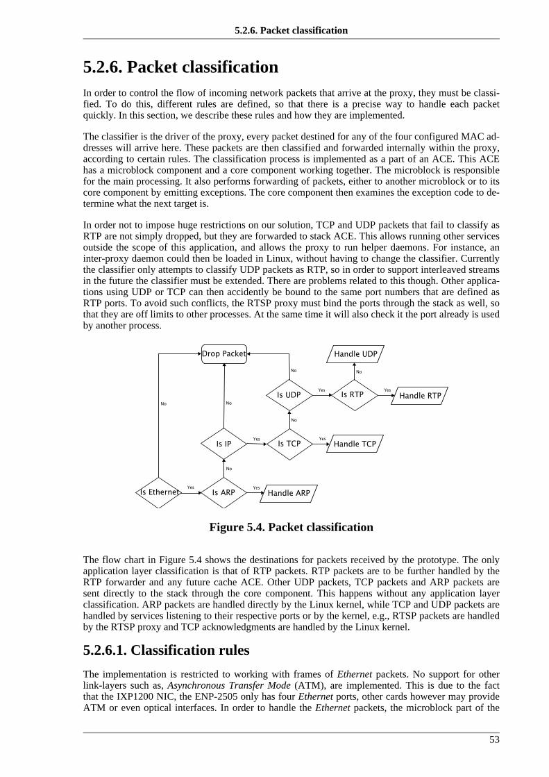
5.2.6. Packet classificationIn order to control the flow of incoming network packets that arrive at the proxy, they must be classi-fied. To do this, different rules are defined, so that there is a precise way to handle each packetquickly. In this section, we describe these rules and how they are implemented.
The classifier is the driver of the proxy, every packet destined for any of the four configured MAC ad-dresses will arrive here. These packets are then classified and forwarded internally within the proxy,according to certain rules. The classification process is implemented as a part of an ACE. This ACEhas a microblock component and a core component working together. The microblock is responsiblefor the main processing. It also performs forwarding of packets, either to another microblock or to itscore component by emitting exceptions. The core component then examines the exception code to de-termine what the next target is.
In order not to impose huge restrictions on our solution, TCP and UDP packets that fail to classify asRTP are not simply dropped, but they are forwarded to stack ACE. This allows running other servicesoutside the scope of this application, and allows the proxy to run helper daemons. For instance, aninter-proxy daemon could then be loaded in Linux, without having to change the classifier. Currentlythe classifier only attempts to classify UDP packets as RTP, so in order to support interleaved streamsin the future the classifier must be extended. There are problems related to this though. Other applica-tions using UDP or TCP can then accidently be bound to the same port numbers that are defined asRTP ports. To avoid such conflicts, the RTSP proxy must bind the ports through the stack as well, sothat they are off limits to other processes. At the same time it will also check it the port already is usedby another process.
Figure 5.4. Packet classification
The flow chart in Figure 5.4 shows the destinations for packets received by the prototype. The onlyapplication layer classification is that of RTP packets. RTP packets are to be further handled by theRTP forwarder and any future cache ACE. Other UDP packets, TCP packets and ARP packets aresent directly to the stack through the core component. This happens without any application layerclassification. ARP packets are handled directly by the Linux kernel, while TCP and UDP packets arehandled by services listening to their respective ports or by the kernel, e.g., RTSP packets are handledby the RTSP proxy and TCP acknowledgments are handled by the Linux kernel.
5.2.6.1. Classification rules
The implementation is restricted to working with frames of Ethernet packets. No support for otherlink-layers such as, Asynchronous Transfer Mode (ATM), are implemented. This is due to the factthat the IXP1200 NIC, the ENP-2505 only has four Ethernet ports, other cards however may provideATM or even optical interfaces. In order to handle the Ethernet packets, the microblock part of the
5.2.6. Packet classification
53

classifier relies on macros provided by the Intel SDK. To support different link-layers one would needdispatch loop macros to handle them. These would probably be supplied by the vendor, or they wouldhave to be written. These macros would then have to be compiled together with the ACE that wishesto retrieve such link-layer frames.
Since we already know that we are receiving Ethernet frames, the first check that must be done iswhether we have an ARP or an IP payload. As shown in Example 5.5, this is done by checking theframe type field of the Ethernet header. If it has a value of 0x0806, we have an ARP packet. The clas-sifier then sets the appropriate exception code and forwards the packet buffer to its core component.First, a dedicated target was implemented as the handler for ARP packets. However, as the decisionwas made to make use of the stack ACE provided by Intel, ARP packets are now forwarded there. Ifthe classifier fails to recognize the packet as an ARP packet, it continues execution by checking thesame field of the Ethernet header to see if it is an IP packet. The frame type of an IP packet is 0x0800,if this comparison fails as well, the packet is dropped, thus restricting support for any other networklayer protocols. This behavior is not regarded as a restriction, as IP is the main network protocol intodays Internet.
Example 5.5. Simple branch classification of Ethernet type
.local etype sd_base;; Load 0x0806 in the GPR etypeimmed[etype, ETH_ARP]
;; The value of the packet header from SDRAM;; is shifted 16 bits, then subtracted from etype.alu_shf[--, etype, -, $$hdr3, >>16]
;; If the result of the alu operation is 0.;; branch to the label ARP_Exceptionbr=0[ARP_Exception#]
;; Load 0x0800 in the etype general purpose register.immed[etype, ETH_IP]
;; Shift and subtractalu_shf[--, etype, -, $$hdr3, >>16]
;; If not equal, branch and drop the packet.br!=0[Drop#]
.endlocal
;; Continue with more IP classification
When the classifier detects an IP datagram, it first verifies that the destination address is equal to theconfigured address of the interface that received the packet. If not, the packet is dropped.
In order to verify the IP address, the microcode has to access shared memory where the configuredaddresses reside. Runtime patching of symbols gives the base address to the memory location fromwhere to search for the address. Each interface has a defined number of 32 bit fields in memory whereMAC and IP addresses are written on startup, or when changed by the configuration application. Whataddress to compare with is uniquely identified by the port on which the packet arrived. This number isthen multiplied with the size of the interface info-block and added to the base address.
Next, if the IP address matches, the transport layer protocol must be resolved. This is done by check-ing the type field of the IP header. If it matches the well-known bit-mask of TCP then a stack excep-
5.2.6. Packet classification
54

tion is set, and the packet is directed towards the core component of the classifier. The core compon-ent then directs the packet to the stack ACE for further application-layer processing.
Example 5.6. IP address validation and transport protocol classification
.local ipt pa;; Read the ip type from the headeralu[ipt, 0, +, $$hdr5]
;; Read more of the IP header from SDRAMalu[boff, off, +, 24] ; Offset from where to readalu_shf[boff, --, B, boff, >>3] ; Convert to Q-Word addrsdram[read, $$hdr0, base, boff, 2], ctx_swap
;; Check that the destination ip address;; is the same as that of the input;; port; to verify that this packet is for the proxyPolPortIp[pa]
;; Get the upper 16 bits of the IP destination addressld_field_w_clr[ip_da, 1100, $$hdr1, <<16];; Get the lower 16 bits of the IP destination addressld_field[ip_da, 0011, $$hdr2, >>16]alu[--, pa, -, ip_da];; If not IP, then dropbr!=0[Drop#]
;; If TCP set exception and send to core.br=byte[ipt, 0, IPT_TCP, TCP_Exception#] ;; Got a TCP packet;; If UDP continue processing.br=byte[ipt, 0, IPT_UDP, ChkPrt#] ;; Got a UDP packet
.endlocal
If the packet is not a TCP packet, a check is performed to see if a UDP packet has arrived. Wheneverthis test succeeds, the microblock will attempt to decide if the packet carries data that is part of a me-dia stream that should be forwarded and/or cached. This decision will be based on the result of a look-up in what we have called “The Media Transport Forwarding Table”, described in the next section. Ifsuch a lookup fails, the default fall back mechanism is to send the packet up the stack to be processedwithout being subject to forwarding.
5.2.6.2. Forwarding table
The “Media Transport Forwarding Table” is used both by the classifier and by the RTP-forwardingcomponents. It enables the classifier to decide which UDP packets to forward and which to send tothe stack ACE. The forwarder component uses the information stored in the table to modify the pack-ets as required.
The forwarding table is implemented as a hash table, as shown in Figure 5.5, where the port number isused as the key. There are several reasons to use the port number as the key. First, it enables the for-warder to be independent of the application layer media transport protocol, e.g., RTP, by not usingany fields in that header. Also, it is more efficient not having to read the RTP header to determine thetype of the packet, as this would involve more processing and memory accesses. The port number isalso located at the same place in both UDP and TCP, so this will make any extension to support inter-leaved streaming easier.
The hash table has the final capacity of N entries. N is a prime that is selected to get a spread in the
5.2.6. Packet classification
55

hash-values and thus avoid collisions when hashing. The session manager will also try to avoid colli-sions by choosing transport ports wisely, so that we have a good probability of achieving perfect hash-ing. Collisions will though be resolved, if any, by inserting keys that hash to the same value in alinked list.
This table is used to lookup forward-information for the majority of packets that are expected to flowthrough the proxy. Therefore it is subject to certain performance requirements. It must therefore notadd unnecessary delay by slow lookups. This is why a hash table was chosen as the primary datastructure for the forwarding table.
Lookups on a “key” should yield an answer in O(1), due to a potential high number of lookups duringa session. This means that a direct lookup on that key must be possible. Also, the hashing functionmust be as simple and fast as possible. Inserts and removals are not that critical as they will be per-formed more seldom compared to lookups, i.e., only when a RTSP session is successfully set up ortorn down.
When choosing the hash function, we realized many ways to optimize it. First, the session managerwill be able to wisely choose ports, by having knowledge about what ports that already have been as-signed to other sessions. Also, since transport ports in RTSP are evenly allocated, i.e., only even num-bers are used for the transport of data, while any data control ports must be odd, we were able to cre-ate a simple hashing function that was easily implemented in microcode. Example 5.7 shows thisfunction.
Example 5.7. Hash function
;; Calculate the modulo of an integer in_x;; and put the result in out_z#macro Mod[out_z, in_x, in_y].local xm
alu[xm, --, B, in_x]Loop#:
alu[out_z, xm, -, in_y]br<0[End#]alu[xm, --, B, out_z]alu[--, xm, -, in_y]br>=0[Loop#]
End#:alu[out_z, --, B, xm]
.endlocal#endm
;; Specialized hash function macro to generate the;; index in the forwarding table#macro Hash[out_z, in_x, in_seed].local x start
immed[start, START_CHANNEL]alu[x, in_x, -, start] ; x = x - startalu_shf[x, --, B, x, >>1] ; x = x / 2Mod[out_z, x, in_seed] ; z = x % seed
.endlocal#endm
;; C-equivalenthash = ((port - START_CHANNEL)/2) % MAX_SESSIONS
5.2.6. Packet classification
56

Figure 5.5. Media Transport Forwarding table
The fields in each client block hold the values which will be used to classify and forward each packet.The classifier makes use of the key and the cache_hint fields to decide the data flow. The key is usedto verify the correctness of the hash, as values potentially may be hashed to the same index. Thecache_hint field is used to decide whether to send the packet to the cacher or not. If this field is set itwill be sent to the cacher and if not it will bypass the cache and is forwarded directly.
Lookup operations. Any incoming packet from the “data source” will be classified according tothese rules: If the packet is a UDP (or TCP, depending on retransmission strategy), check the forward-ing table for an entry. If an entry exists, i.e., there is an address != 0 at the hashed index + base ad-dress, go to this address and check if the key is equal to the destination port of the incoming packet. Ifnot, a possible collision has occurred, or faulty behavior is detected. Two options to handle this areavailable. One could simply give up, or resolve the collision by traversing the next address until amatch is found in the list. If the end of the list is reached (i.e., the next address equals zero), an errorhas occurred. This could be a random host sending packets into the oblivion or a malicious DDoS at-tack. Checking the IP to match any of those it is expected to be should resolve this by quickly drop-ping the packet if a mismatch is found. This relates to how many servers a proxy is helping. If there isa match, then a number copies of the packet will be made, depending on the number of clients havingrequested the file/stream/object, also, if the cache hint is set, then a copy should be sent to the core ofthe classifier for further treatment. The number of copies made is the same as the number of sub-sequent key matches found in the list of client blocks. The copies will be altered according to the in-formation in the client block and then sent to the egress ACE which puts it on the correct interface.
Insert operations. When a SETUP message is received by the RTSP proxy, it must, if the whole ob-ject is not present in the cache, forward the request to (the server or neighboring proxy) a source hold-ing the whole object. When doing this, it must record the client port it will use, along with the IP andwhether the object should be cached or not. It will also have to insert the port that it expects incomingRTP packets on. This is not known, until the server replies to the SETUP message that is forwarded.However, in the forwarded SETUP message the proxy may announce the client port of its wish. As-suming that this wish is granted, the proxy should choose the port based on the next free address inthe forwarding table. This will allow ports to be assigned without creating collisions in the hash table.If the server chooses another port that collides with an already set port, the insert operation will beslower, as the end of the list must be found before inserting the block. If other clients already have re-quested the data from this server a traversal of the list is also needed, before inserting the block.
Remove operations. Removing a “client block” from the forwarding table will depend on the con-flicts within it. If no conflicts are present, any removal will be fast. This operation will occur everytime a session is torn down or when timeouts are reached. These removals will occur in the same rateas inserts, so they need not be as fast as lookups.
5.2.7. RTP forwarding
57

5.2.7. RTP forwardingThe RTP forwarding functionality is implemented in the same ACE as the classification. This is doneto simplify the code and to lower any inter-microengine communication. The forwarding can be im-plemented as a standalone microcode executable, and in a fully fledged system where the proxy alsoperforms caching this might be needed. This will depend on how the caching functionality is imple-mented. However, when we perform this in the same microblock as the classification, we can moreeasily perform measurements on the performance.
The forwarding code basically uses the lookup information from the forwarding table described inSection 5.2.6.2. The close integration with the classifier, allows this to happen in just one memory ac-cess, i.e., the values needed for header modification are stored in local registers after the classifier hasmade the lookup. The values retrieved on a lookup are those shown in Figure 5.5. They include theclient IP address and the pair of ports that are set up in the session, i.e., the RTP and RTCP ports an-nounced by the client. Also, a cache flag is retrieved in order to know if packets are to be written tothe cache.
The information needed to forward a packet includes more attributes than the information retrievedfrom the forwarding table. The code needs access to the MAC destination address. As our test setup isknown, this information is hard coded in the prototype, but it should be implemented as an ARP-cache in a fully fledged system. This can be done by storing the destination ARP from the incomingRTSP requests in a shared table. By hashing the destination IP address to the indexes in the table, onewould get a fast way to retrieve a MAC address based on an IP address. If no mapping is found in thetable, an exception can be set, and the packet can be handled by the StrongARM core component, byissuing an ARP request. Another way to solve this could be by exposing the kernel ARP-cache to themicroengines. Doing this would require less replication of data in memory, and would better utilizethe finite memory resource.
When the forwarder has all the information needed to forward a packet, it first modifies the Ethernetheader and then the IP and UDP header. The existing destination IP is written to the source IP fieldand the destination field is overwritten with the IP retrieved from the forwarding table. Then, afterwriting the new values to SDRAM, the IP checksum is updated to reflect the changes. This is done in-crementally according to RFC 1624 [Rijsinghani94] and is implemented in microcode as shown inExample 5.8. What this means is basically that for every modified 16-bit field in the IP or UDP head-er, the old value is removed from the checksum and the new value is added. These calculations areperformed using one-compliment arithmetics.
Example 5.8. Incremental checksumming
#macro IncrementCksum[out_newsum, oldsum, old, new].local sum tmp mask
immed[mask, 0xffff]alu[sum, --, ~B, oldsum] ; sum = ~oldsum;alu[sum, sum, -, old] ; sum = sum - old;alu[sum, sum, +, new] ; sum = sum + new;alu[tmp, sum, AND, mask] ; tmp = sum & 0xffffalu_shf[sum, tmp, +, sum, >>16] ; sum = tmp + (sum >> 16);alu[tmp, sum, AND, mask] ; tmp = sum & 0xffff;alu_shf[sum, tmp, +, sum, >>16] ; sum = tmp + (sum >> 16);alu[sum, --, ~B, sum] ; sum = ~sum;alu[out_newsum, sum, AND, mask] ; return (sum & 0xffff);
.endlocal#endm
5.2.7. RTP forwarding
58

The UDP destination port field is also modified to reflect the entry in the forwarding table, and thesource port field is copied from the existing destination port in the header. However, the destinationport is not used by the server in this case, as RTP packets are only flowing in one direction. The UDPchecksum is for now set to zero in the prototype, as our point of reference in Chapter 6 also does this.
When all the fields are modified and written to the packet in SDRAM, the ACE enqueues the packetfor transmission by the egress ACE.
5.2.8. SummaryOur prototype implements basic proxy functionality to show that application layer forwarding can beoffloaded on to the IXP1200. Though it is not a fully fledged system for production use, it implementsenough functionality to verify its usefulness and give a proof-of-concept. It successfully sets up ses-sions in the control-plane, it conveys information needed to perform forwarding in the fast-path of theIXP1200 and implements the forwarding functionality needed to collect measurements. These will bedescribed and analyzed in the next chapter, where we conduct some controlled experiments on ourprototype and analyze these with respect to our goals.
5.2.8. Summary
59

60

Chapter 6.
Experiments, results and analysis
It is inexcusable for scientists to torture animals; let them make their experiments onjournalists and politicians.
—Henrik Ibsen
Our experiments will first and foremost time the processing done by the classifier/forwarder ACE inthe implementation. We attempt to accurately measure the time spent by every RTP/UDP packet with-in the forwarding procedure. This chapter will also analyze the work done in this thesis. It will do sowith respect to the information in Part I, and to the results gained from our experiments.
6.1. Testing environmentOur testing environment, shown in Figure 6.1, consists of one IXP1200, ENP-2505 [Radisys03] cardthat is connected to the PCI bus of an Intel Pentium 4 2.0 GHz, Dell Optiplex GX260. Since all exper-iments are conducted within the IXP1200 card, the host machine is free to run the Darwin StreamingServer [Apple04] and the client without affecting the results.
The Darwin Streaming Server is an open source version of the proprietary Quick Time StreamingServer. It claims to be compliant to the Internet standards RTSP, RTP and SDP.
The client is a dummy python program that communicates with the proxy through the socket inter-face. It only sets up the RTSP session and receives the stream of incoming RTP packets in a selectloop.
One of the four 10/100 Mbps Ethernet interfaces on the IXP1200 is connected to a switch, as is thehost. All network communication will flow back and forth through the switch as shown in Figure 6.1.
Figure 6.1. Test configuration
61
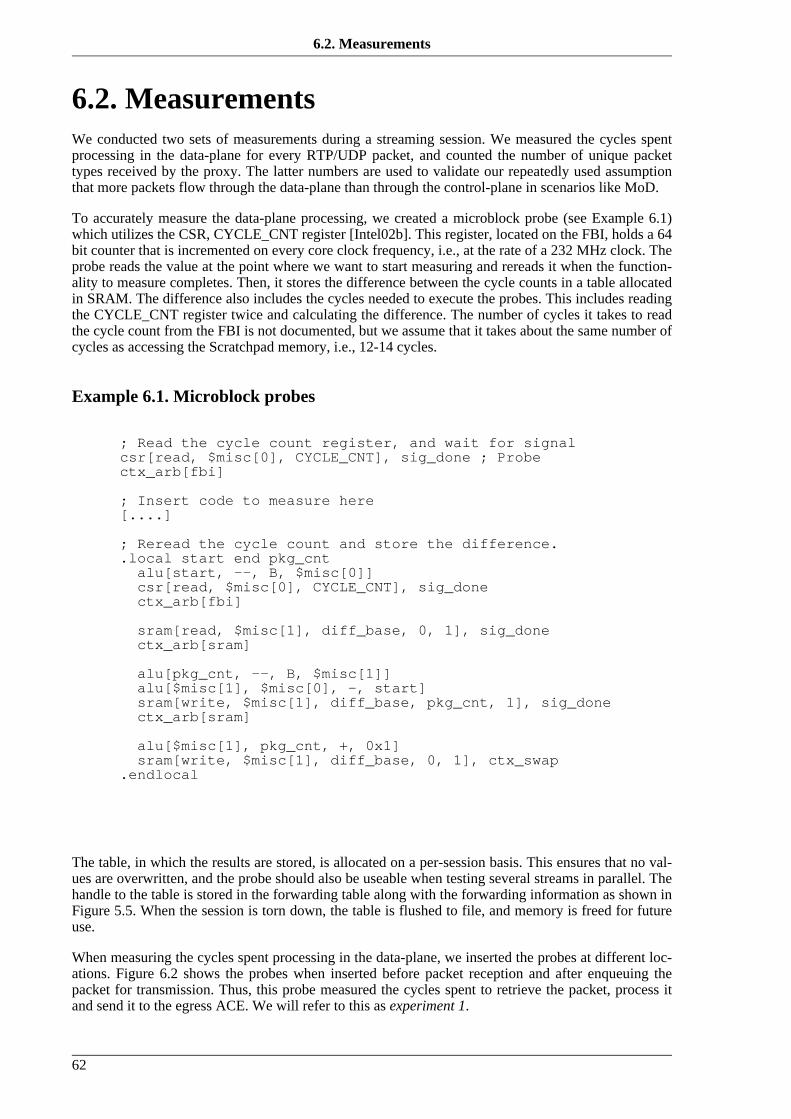
6.2. MeasurementsWe conducted two sets of measurements during a streaming session. We measured the cycles spentprocessing in the data-plane for every RTP/UDP packet, and counted the number of unique packettypes received by the proxy. The latter numbers are used to validate our repeatedly used assumptionthat more packets flow through the data-plane than through the control-plane in scenarios like MoD.
To accurately measure the data-plane processing, we created a microblock probe (see Example 6.1)which utilizes the CSR, CYCLE_CNT register [Intel02b]. This register, located on the FBI, holds a 64bit counter that is incremented on every core clock frequency, i.e., at the rate of a 232 MHz clock. Theprobe reads the value at the point where we want to start measuring and rereads it when the function-ality to measure completes. Then, it stores the difference between the cycle counts in a table allocatedin SRAM. The difference also includes the cycles needed to execute the probes. This includes readingthe CYCLE_CNT register twice and calculating the difference. The number of cycles it takes to readthe cycle count from the FBI is not documented, but we assume that it takes about the same number ofcycles as accessing the Scratchpad memory, i.e., 12-14 cycles.
Example 6.1. Microblock probes
; Read the cycle count register, and wait for signalcsr[read, $misc[0], CYCLE_CNT], sig_done ; Probectx_arb[fbi]
; Insert code to measure here[....]
; Reread the cycle count and store the difference..local start end pkg_cntalu[start, --, B, $misc[0]]csr[read, $misc[0], CYCLE_CNT], sig_donectx_arb[fbi]
sram[read, $misc[1], diff_base, 0, 1], sig_donectx_arb[sram]
alu[pkg_cnt, --, B, $misc[1]]alu[$misc[1], $misc[0], -, start]sram[write, $misc[1], diff_base, pkg_cnt, 1], sig_donectx_arb[sram]
alu[$misc[1], pkg_cnt, +, 0x1]sram[write, $misc[1], diff_base, 0, 1], ctx_swap
.endlocal
The table, in which the results are stored, is allocated on a per-session basis. This ensures that no val-ues are overwritten, and the probe should also be useable when testing several streams in parallel. Thehandle to the table is stored in the forwarding table along with the forwarding information as shown inFigure 5.5. When the session is torn down, the table is flushed to file, and memory is freed for futureuse.
When measuring the cycles spent processing in the data-plane, we inserted the probes at different loc-ations. Figure 6.2 shows the probes when inserted before packet reception and after enqueuing thepacket for transmission. Thus, this probe measured the cycles spent to retrieve the packet, process itand send it to the egress ACE. We will refer to this as experiment 1.
6.2. Measurements
62

Figure 6.2. Experiment 1: Cycle probes for packet reception, forwarding andenqueuing
Figure 6.3 shows experiment 2. The probes were now inserted before starting packet classification,header modification and checksumming and before enqueuing the packet for transmission.
Figure 6.3. Experiment 2: Cycle probes for packet forward processing
Finally, in Figure 6.4, we show the third experiment that was conducted to measure the cycles spentforwarding and enqueuing the packets. This was basically done to find the total time needed for in-gress processing.
Figure 6.4. Experiment 3: Cycle probe for packet forward processing andenqueuing
During every run of our cycle count tests, the client requests a media object that has been previouslyhinted, i.e., knowledge about what to request in the RTSP SETUP message has been retrieved manu-ally. The object requested is a 300 Kbps media file, encoded in the Quick Time movie format, storedon the host by the Darwin server. The Darwin server sends RTP packets with a constant size of 1024bytes.
6.3. ResultsIn this section, the results of our measurements are presented and explained. First, we present therange of packet types received by the proxy, and then, results and graphs of the data-plane processingare shown and discussed.
6.3. Results
63

6.3.1. Packet typesTable 6.1 shows the distribution of packets received at the proxy during the streaming of the test ob-ject. In this case over 99% of the traffic received is stream data, while under one percent is controlmessages. A similar distribution could be expected in MoD systems in general. For larger and longermedia objects, the number of RTP/UDP packets would probably be higher, and the number of RTCPpackets would also be higher as the duration of the session would be longer. Note that the client doesnot send any RTCP messages, they are only received from the server. In a real system, the clientwould also be sending these, thus increasing the number of RTCP packets further.
Nevertheless, the conclusion from this packet count experiment is that, as expected, far more packetsare processed in the data-plane compared to the control-plane. Thus, the data-plane is the place to op-timize first to gain as high performance improvement as possible.
Table 6.1. Packet count during sessionPacket type Count Percentage Comment
TCP 8 0.25% RTSP, handshake and acknowledgments
RTP/UDP 3131 99.2%
RTCP/UDP 17 0.53% Only sent by the server
Other 1 0.03% ARP packets and packets with bad checksums
6.3.2. Ingress to egressIn experiment 1, shown in Figure 6.2, we measure the cycle count for ingress to egress processing.The results of this experiment are shown Figure 6.5. It shows the number of cycles needed to pro-cesses every incoming RTP packet at the proxy. The processing includes packet reception, packetclassification, checksumming, header modification and enqueuing. Table 6.2 shows statistics derivedfrom these measurements.
As seen in the figure, most packets are processed in about 1325 cycles. In fact, calculations show that88.2% of all packets are processed within a range of 1320 and 1330 cycles. This is also indicated bythe median value of 1326. However, some packets deviate quite a bit from the main distribution. Thedifference between the maximum and the minimum value is 356 cycles, and the unbiased standard de-viation of the distribution is 36.3. The deviation will be further discussed in Section 6.3.3
6.3.2. Ingress to egress
64

Figure 6.5. Cycles counted during packet reception, forwarding and enqueuing
Table 6.2. Ingress to egress statisticsMeasurement Cycles
Maximum 1630
Minimum 1276
Average 1331
Median 1326
Unbiased Standard Deviation 36.3
To further visualize the results, a snapshot of packets 500 through 700 from Figure 6.5 is shown inFigure 6.6. We observe that although most packets need about 1325 cycles to be received, processedand enqueued, every now and then a packet deviates from the pattern.
6.3.2. Ingress to egress
65

Figure 6.6. Packets 500 through 700 experiment 1
6.3.3. DeviationWe have, in experiment 1, shown the total number of cycles needed to receive, process and enqueue apacket through the prototype. We have noticed that a few percent of the packets deviate quite a bitfrom the rest. Analytically, we would however expect that the processing cost of our classification andmodification of the packet in experiment 2 (see Figure 6.3) would be close to a constant cycle count.This is based on the fact that every packet we send through our microblock follows the same flow andrequires the same amount of processing. Figure 6.7 a) shows the number of cycles spent performingthe functionality in our second experiment. Surprisingly, a few packets are still deviating from thegeneral pattern. Though the measurements stabilize somewhat, the difference between the maximumand the minimum is still large, i.e., 204 cycles, and the standard deviation is 22.5.
6.3.3. Deviation
66

Figure 6.7. Cycles counted during packet forwarding
Figure 6.8. Packets 500 through 700 from experiment 2a)
6.3.3. Deviation
67

The results shown in Figure 6.8 are packets 500 through 700 from our second experiment. The figureshows a similar spread of values as in the previous closeup in Figure 6.6. In this case, the most ex-treme values are inside the range, so we get the outliers around packet 660.
To understand why some of the packets require more cycles to be processed, we conducted three vari-ations of experiment 2. There are a number of things that could interfere with the processing of pack-ets. In the microblock that performed classification and forwarding, we yielded on every memory ac-cess. This allows other threads to run, if they are in ready state. Also, the microengines all share thecommand bus as shown in Figure 4.6. Because they share this bus, they also contend for it. This con-tention can make some memory requests wait longer, as other requests might already be in the queue.Also, to send a request to one of the three command queues, the command bus arbiter must grant ac-cess to the bus, and finally, there are variations in memory latency as shown in Table 4.2.
We wanted to assure that no scheduling would occur while we did the cycle count. To achieve this,we altered the code so that our thread would stay in control of the microengine even if it was idlewaiting for a memory access, i.e., the processing was done as an atomic operation. We ran the atomicoperation in three “modes”. First, all memory accesses were ordered, then we allowed the hardware tooptimize them, and finally, we sent them all through the prioritized command queue. This exercisewas done to see if there was any contention from other microengines, i.e., those running the egressACE. If there was, the optimized and prioritized memory accesses should yield less deviation. Theresults of the three scenarios are shown in Figure 6.7 b-d) and statistics are shown in Table 6.3. Eventhough they show a slightly better distribution, there are marginal differences between the threememory access “modes”. What is clearly seen, is that several measurements are stabilized when com-paring a) and b) on Figure 6.7. One plausible explanation for this is that four threads are running onthe microengine, and whenever the microblock in the non-atomic ordered scenario makes a memoryrequest, it swaps out, to allow other threads to do their work. This means that the threading arbiter unitwill schedule the other threads in a round-robin fashion, and if any of them are ready, they will getcontrol of the microengine. As all threads run the same code, and we only have one connected inter-face, none of the other threads should be ready. Otherwise, having them poll the Ready Receive bitsshould fail and they swap out again. The latter is not very likely, as it would probably give a higheroverhead than measured. However, there seems to be some activity unaccounted for, as the deviationon Figure 6.7 a) is far greater on some of the packets than what is documented to be the cost of a con-text-switch, i.e., about three cycles.
Table 6.3. Forwarding statisticsExperiment scenario Max Min Average Median Std. devi-
ation% in
range632-644
1. Non-atomic ordered forwarding 838 634 644 638 22.48 91.9%
2. Atomic ordered forwarding 750 632 641 638 15.98 94.7%
3. Atomic optimized forwarding 728 634 641 638 15.93 94.6%
4. Atomic prioritized forwarding 730 634 641 638 15.70 94.8%
The best explanation we could find for why certain packets need more cycles than others, is thememory latency differences. Our microblock makes eight memory access while processing the pack-et, 3 SRAM read operations, 3 SDRAM read operations and 2 SDRAM write operations. If we takethe maximum variation in delay, this gives us 47 cycles. This does however only add up to about halfof the deviation experienced in the three atomic measurements and even less in the non-atomic scen-ario!?
6.3.4. Processing overheadIn the two first experiments, we measured the processing overhead from ingress to egress and how
6.3.4. Processing overhead
68

much of this overhead was added within our forwarding procedure. To complete our range of possibleexperiments, we did, as our final experiment, measure the overhead of forwarding and enqueuing asshown in Figure 6.4. The results from experiment 3 gives us the opportunity to show how much over-head is added in specific parts. An approximate average enqueuing delay can be calculated by sub-tracting the average from the non-atomic and ordered scenario in experiment 2 from the average ofexperiment 3. The same goes for ingress processing. The separation of where processing delay is ad-ded is shown in Table 6.4.
We see, from the table, that most of the processing overhead is added in our classification and for-warding ACE.
Table 6.4. Experienced overheadFunctionality Average overhead in cycles Average overhead in µs
Ingress processing 493 2.13
Classification and forwarding 644 2.78
Enqueuing for egress 194 0.83
6.3.5. Summary of resultsThe implemented prototype offloads basic RTSP/RTP proxy functionality onto the IXP1200 NPU. Itoffloads the host machine by processing all network traffic flowing through the proxy, both in thecontrol-plane and in the data-plane. This leaves all the resources in the carrier machine unused andfree for other purposes, e.g., transcoding and protocol translation.
In the control-plane, the prototype performs basic RTSP forwarding and data-plane control. It does soby utilizing the embedded StrongARM processor for packet processing and setting up shared datastructures that are later used by the microengines, when they process packets in the data-plane.
In the data-plane, the prototype shows that one microengine thread is able to perform forwarding ofRTP/UDP packets. This includes packet reception, classification, checksum validating, header modi-fication and checksum recalculation.
The prototype is able to process every RTP/UDP packet in an average of 1331 cycles, with not count-ing the cycles needed for the egress ACE to pull data from SDRAM to the TFIFO queues. We haveshown that that packets are not processed at a constant cycle rate. We have suggested that schedulingoverhead and memory latency are probable causes for this variation.
6.4. The offloading effectOne interesting aspect is how well the prototype offloads the host carrier. As a point of reference, weuse the results found by Guo and Zheng [Guo00], explained in Section 3.4.2. Their measurementsshow that the reception of a 1024 byte large UDP packet in the GNU/Linux 2.0.34 kernel takes 35 µs.Converted to cycles using a 350 MHz clock the reception takes 12250 cycles. Sending a packet of thesame size requires less processing and employ DMA. It takes 18.9 µs to send a UDP packet withoutcalculating the checksum, i.e., it takes 6615 cycles.
The prototype handles all the network traffic sent to the host, so it effectively offloads 100% of thenetwork processing from the host CPU. This means that a sum of 18865 cycles are free to be utilizeddifferently by the host every time a 1024 byte packet is received and handled by the prototype. In ad-dition, any application layer processing is also offloaded to the NPU.
The offloading effect will largely depend on the network load on the proxy host. The distribution ofpackets shown in Table 6.1 suggest that the network load is significant in the data-plane. Although all
6.3.5. Summary of results
69

traffic is offloaded by the prototype, 99% of the traffic flows in this data-plane, and this is where theoffloading will have real effect. The host carrier would have no problems processing the control-plane, as this would only require processing a mere 1% of the traffic or less.
Now, this scenario seems very promising, but it is a highly simplified view of an MoD proxy-cache.As explained in Section 3.2.2, the algorithms developed for MoD caching try to reduce the networkload. They do this by relieving the network between the proxy and the server. This means that thetraffic flowing through the proxy also is reduced, as every cached segment of data will be sent directlyfrom the proxy. The amount of traffic that a caching strategy reduces, depends on how well it predictswhat to keep in the cache, and what to replace. It also depends on how much of each object the proxy-cache is able to store.
Some MoD caching replacement algorithms take popularity in account when deciding what objects toreplace or keep. The Zipf distribution explained in Section 2.3, says that 10% of the movies are ac-cessed 90% of the time, due to their popularity. In a caching algorithm that replaces objects based onpopularity, we suggest three coarse grained offloading scenarios to be discussed based on the Zipf dis-tribution. These include best case Zipf, worst case Zipf and a middle ground.
• Best case Zipf caching: In the case where a caching strategy is able to perfectly cache according tothe Zipf distribution, 90% of all accesses can be served directly from the proxy-cache, given thatthe proxy has enough space to store 10% of all media objects. This means that the offloading po-tential is only 10% using our prototype, i.e., 9.9% in the data-plane processing.
• Worst case Zipf caching: In this case, the cache algorithm totally fails in following the Zipf distri-bution and all data must be fetched from the server and be forwarded through the proxy, i.e.,100% of all traffic. This means that the offloading potential is 99% using the prototype.
• Middle ground: This scenario would give a caching hit-rate in between the worst case and the bestcase scenarios. To serve the middle ground scenario, we suggest using an intelligent replacementalgorithm like ECT, explained in Section 3.2.2. ECT shows good simulation results when servinglarge client populations and many movies.
If we assume that a cache achieves the best case cache hit-rate, the offloading potential is only 9.9%and all resources should be allocated to help pushing data from the cache as 90% of the requests canbe served directly. However, a perfect Zipf distribution is unlikely to occur. It is hard to model thetheoretical Zipf distribution accurately in a caching scenario. The popularity of movies change dy-namically, and fluctuations may occur based on lurker variables, e.g., the release of sequels to a moviecan increase the popularity of the original. Also, the Zipf distribution is claimed to be inaccurate whendealing with large client populations and when the number of media objects is high. [Griwodz00]Even if the best case is achieved, most media caching schemes assume that only a part of the object isstored in the cache due to the high storage requirement (see Section 3.2.2). Therefore, the missingparts of a stream must be fetched from the server. These data must be forwarded by the proxy and caneffectively be offloaded by our prototype.
The worst case Zipf is also an unlikely scenario, as most caching algorithms, no matter how simple,are able to preserve some cache hits. In shorter periods it might, however, be that cache misses are re-peatedly experienced. In such a period, the offload effect would be significant.
The middle ground scenario is assumed to be most likely. An intelligent caching algorithm canachieve near perfect hit rates in periods, but periods with massively cache misses can also be experi-enced. Nevertheless, caches are not able to store all the media objects entirely and fluctuations in theaccess patterns will require that much data is fetched from the server.
Determining quantitative measures of how much traffic in the data-plane must be retrieved from theserver is dependent of several variables, e.g., the number of concurrent streams that are flowingthrough the proxy and the bit-rate at which they are sent. Large-scale experiments or simulations areneeded to get empirical data on this. The data-rate is of course limited by the available downstream
6.4. The offloading effect
70

18This number is scaled down to a 232 MHz processor. The 350 MHz CPU used in [Guo00] would use 53.9 µs plus applicationlayer processing.19Studying the Intel source code suggest that egress processing requires less processing per packet than ingress processing, asingress ACE first moves mpackets into the RFIFO, and then to SDRAM, while the egress ACE only transfer a mpacket fromSDRAM to the TFIFO queues. Also, the results from [Spalink01] show that their egress uses 109 cycles.
bandwidth. With the IXP1200 NIC used in this thesis, the maximum aggregate bit-rate is 400 Mbps,but newer cards support 3 Gbps and more.
The caching of media objects and offloading of fast forwarding of stream data are clearly orthogonalmethods to improve an MoD system. The caching reduces startup latency, network load and serverload while the offloading alleviates network processing within the proxy. The offloading effect is inno way dependent on how well the offloaded solution performs. The number of freed cycles will beavailable to the proxy host, no matter how long it takes the prototype to process the same packets. Theperformance of the prototype is still important, but it does not have any impact on the offloading ef-fect.
6.5. Prototype performanceThe performance of the prototype can be compared to that of a traditional OS architecture, where asocket interface is employed to handle network traffic. We will compare our performance to that ofsuch an architecture, i.e., the Linux stack. As no measurements of the egress cycle count was per-formed, due to time constraints, we will only compare the reception of packets. This should be enoughto prove the concept.
The data in Section 3.4.2 shows that the Linux OS is, with an Intel Express 100pro NIC, able to re-ceive 1024 byte large UDP datagrams using 12250 cycles per packet. This processing overhead doesnot show any application layer processing. Our results also show how many cycles it takes to receivea packet, but they also show the cycles needed to perform application layer RTP forwarding. Thismeans that the comparison is slightly biased towards the Linux cycle count, due to the coarse granu-larity in our measurements.
Still, we see that our prototype performs reception functionality at a much lower cycle count. The pro-totype uses an average of 1137 cycles (493 + 644) versus 12250 cycles in the Linux stack. Of course,a NIC with support for DMA on the receiver side in the same Linux environment would probably per-form slightly better. But, the origin of the main addition to the delay is not in the transfer from theNIC, but higher up in the stack, as explained in [Guo00].
It takes our prototype less than one tenth of the cycles to receive a 1024 byte UDP packet, comparedto a traditional architecture. The implication of this, is that the total delay of every packet flowingthrough the system is reduced. In the Linux case, every packet being forwarded would be delayedmore than 81.3 µs18, as application layer processing overhead also would have to be considered. If weassume that the egress ACE in the prototype is able to send packets using approximately the sameamount of cycles as the ingress19, i.e., 493, the prototype overhead amounts to a total of 7.9 µs perpacket. This means that the delay of each packet is reduced by 73.4 µs.
The four 100 Mbps interfaces on the IXP1200 NIC can sustain a maximum aggregated data-rate of400 Mbps. Further, the maximum throughput of a forwarder using 7.9 µs per 1024 byte packet is 1036Mbps. This is a good indication of that there are plenty of resources left for other processing withinour microblock, such as caching. This is even more evident, as we neither employ parallelism, norutilize more than 2 microengines; one for ingress, classification and forwarding and one for egress.
In an MoD scenario, buffering is used at the end nodes of the system to compensate for jitter. Thismeans that reducing the delay in a proxy has little impact on the user experience of a streamed movie.However, the forwarding functionality of the prototype might be more applicable in a real-timestreaming scenario, e.g., in a distributed game or a video conference, were no buffering is used. Ima-gine a real-time game, where the contestants continuously send events that update the game state.Also, they can team up, and have real-time communication while playing. Proxies have been proposedas a way to offload servers in network gaming [Mauve02]. If the real-time traffic must pass through
6.5. Prototype performance
71

the proxy, it becomes more important to reduce the delay of every packet. Our prototype proves theconcept of such reduction. Also, it might be practical in real-time video conferencing. In a video con-ference with three participants, a proxy could perform overlay multicast of the streams flowing backand fourth, so that the number of unicast streams can be reduced. Adding as little delay as possiblewould be beneficial in this scenario as well.
The clock speeds of the processing units used by the IXP1200 and the Linux test machine were re-spectively 232 MHz and 350 MHz. In order for the Linux architecture to receive the packet and addless delay than the NPU, it will need a CPU with a clock speed over 1.570 GHz. 232 MHz for theNPU, and 350 MHZ for the GPP are, however, not representative for the technology available at thetime of writing. GPPs have reached 3.2 GHz frequencies, and microengines from Intel have reached1.4 GHz. If we recalculate the number of cycles and compare the two, we see that a 3.2 GHz GPP willexecute the cycles needed for reception in 3.8 µs and the NPU will use 0.8 µs. This implies that theNPU still would be 4.75 times faster, even though the comparison still is biased towards the GPP.
The prototype forwarding functionality seems to perform well, as was expected, due to the use of spe-cialized hardware for network processing. The processing also becomes far less complicated whenimplemented on an NPU, compared to a fully fledged socket interface, such as the Linux stack. Theprototype does, however, have the potential to perform even better. The implemented forwardingfunctionality is not fully optimized, and ingress and egress processing may be improved. We performsome unnecessary validity checks in our code, such as verifying the IP address of the packets re-ceived. The ingress does the same check, based on the MAC addresses, so this could be removed. Fur-ther, the prototype does not make use of parallelism, which is one of the primary benefits of theIXP1200.
6.6. ExtensionsIn addition to optimizations, several extensions in functionality are needed to make the prototype afully fledged MoD proxy. Possible extensions include caching, caching algorithms, zero-copy fromnetwork to disk, zero-copy from disk to network, prefetching from server and efficient communica-tion with host applications.
6.6.1. CachingThe primary functionality of an MoD proxy is caching. In other multimedia applications, such as dis-tributed gaming, proxies would typically not cache media data, but rather game state. In this sectionwe will describe how caching segments of data in the MoD proxy prototype could be performed. Thedescription will deal with the implementation details for the microengines.
The basic functionality needed in order to implement caching functionality running on the microen-gines, involves memory copying of RTP packets. This is because we would like to minimize the pro-cessing done on the microengines and leave the actual disk writes and stripping of headers to pro-cessing units higher up in the hierarchy, e.g., the StrongARM or the host CPU. Therefore, a copy ofthe packet must be made so that it can be both forwarded and cached. This process should add as littledelay to the packets as possible, to preserve the throughput of the prototype and because every packetin a stream will be copied to the cache until the caching strategy is satisfied. The number of packetscopied will of course depend on the caching strategy (see Section 3.2.2).
We suggest two possible ways to go about implementing the “multicast” of packets. Both approachesinvolve changes to the Intel IXA SDK, but one more than the other. The easiest way would only re-quire changes to the configuration tools. The other would require touching several core components,e.g., ingress, egress and the resource manager, but the configuration tool could stay the same.
The most intuitive way to implement copying on the microengines, is to dedicate one microengine tothe task. Again, two options are available: four threads running on the microengine can copy onepackage each, or one thread can copy several packages. The former can use every thread to dequeueone packet handle each, sequentially read from it, and write to an allocated buffer. By yielding on
6.6. Extensions
72

every read and write, some memory latency is hidden, as every thread may process while the othersare waiting for a memory request. A possible way to implement the latter approach is shown in Ex-ample 6.2. It is essential that packet copying hide as much memory latency as possible, so that theprocessing resources are utilized. The pseudo code in the example does this by allowing several con-tinuous reads, followed by several writes. The writes will have to wait for the reads, so more latencywill be hidden when there are several packets to copy.
Example 6.2. Pseudo code for packet copy
while(1) {packetReady = checkQueue();
if (!hasFreeCopySlot() && !packetReady)goto copy;
freeSlot.handle = dequeue();freeSlot.size = getSize(freeSlot.handle);freeSlot.duplicate = allocate(size);slots.add(freeSlot);
copy:for(everySlot)slot.bytes = read(&sdramRegs, slot.handle);
for(everySlot) {write(sdramRegs, slot.duplicate);slot.size -= bytes;if(slot.size == 0) {
signal(ingress);sendTo(strongARM, slot.duplicate)
}}
}
The other way to multicast packets is to have every duplicate of the packet share the payload, andonly copy the headers when they are modified. Using this “lazy copy” strategy requires more logic inthe buffer management, and the code must be modified in the ingress, egress and the resource man-ager components. We suggest that a data structure like the one in Figure 6.9 can be used for this pur-pose. Every packet is represented by a pointer to its header and a pointer to its payload structure. Thepayload structure holds a reference counter for every copy of the header, i.e., the number of packetcopies. Every time a copy of the packet is needed, the reference count is increased. The first modifica-tion of a value in a packet results in the header being copied to a free memory location, but as nomodification is done to the payload, every copy can share this. Whenever a component is done withits copy, the reference count is lowered and any modified header is freed. When the reference countreaches zero, the payload is also freed.
6.6.1. Caching
73

Figure 6.9. Lazy copy data-structure
The lazy copy strategy is by far the best of the two, as it requires a smaller portion of the packet to becopied. If a 1024 byte large packet were to be copied in the first solution, it would require sixteen64-byte chunks to be read, and then written. In memory latency alone, this would amount to about1600 cycles, or 6.8 µs, on a 232 MHz microengine. Some of this latency would be hidden, but wouldstill represent a significant increase of the total delay added to every packet flowing through the proto-type. Performing lazy copying would make it far more efficient to copy packets. It only requires theheaders, e.g., 42 bytes for an UDP packet, to be copied and this would only happen if it was modified.Further, when combining copying with forwarding all modifications can be written directly, thus re-ducing the number of memory writes.
The main reason for not implementing caching in the existing prototype was time. We realized thatchanging several components in the SDK is too extensive for our time frame. The caching functional-ity is needed to get further data on how well an NPU is suited for offloading an MoD proxy cache.Also, as the microengines will only perform a packet copy, and further caching logic is left to behandled by a processing unit higher up in the hierarchy, the packet copy is, as mentioned, actually amulticaster of the packet. This can also be used in situations where IP multicast is unavailable, to cre-ate overlay multicast.
6.6.2. Zero-copyAnother interesting extension to the prototype is to investigate how to make zero-copy data pathsfrom the network to disk and from the network to the application. This is relevant to caching, but canalso be applicable in other cases, e.g., when a server stores a live recording from a client, or if payloaddata must be modified by a proxy performing transcoding, application layer encryption or re-encoding. We suggest how a zero-copy data-path, from network to disk, may be designed for our pro-totype.
Figure 6.10 shows the traditional data-path from network to disk and a zero-copy from the network tothe disk. The traditional data-path requires data to be moved from the NIC to a kernel memory buffer,either by a DMA transfer or by a CPU driven transfer. On a regular NIC, this happens every time apacket is received. Then, packet data must be copied to an application buffer, due to memory protec-tion, before the application can issue a disk request. For every disk request, the data is again copied tokernel memory. Usually, the kernel will buffer several requests, before flushing them to disk. As wesee, the traditional data-path is slow, due to many interrupts and memory operations on packets anddata.
The figure also shows a zero-copy path from an NPU, into kernel memory and down to disk. The ideais to reduce the number of memory operations, interrupts to the kernel and small disk requests. A pos-sible way to solve these three goals is to make use of NPU features and memory resources. Packets re-ceived by the NPU can be batched in memory, so that a certain amount of packets are buffered. When
6.6.2. Zero-copy
74

20We are unaware of any scatte-gather support on the IXP1200, but instead a DMA transfer could be issued per packet payload.
the set amount of packets are received, the NPU will issue a scatter-gather DMA20 transfer of thebatched packet payloads into a continuous block of kernel memory. As several packets worth of dataare transferred on every turn, the 0number of interrupts to the kernel can be dramatically reduced, de-pending on how many packets it is expedient to batch. Since the different payload segments aregathered during the transfer, no internal kernel copy operations are needed.
As disk requests are very slow, i.e., typically one order of magnitude slower than memory access, theyshould be few and large. Therefore, the kernel I/O system should collect several batches of payloadsand send them to disk in one large disk-write.
Figure 6.10. Zero copy data-path vs. traditional data-path
We suggest a similar approach for a zero-copy data-path from the network to the application. The dif-ference is that the batched payloads, or rather the whole packets, should be transfered directly to ap-plication memory, so that the packet may be processed and then effectively sent back to the card. Thisis possible only if the NPU does all the TCP/IP processing, which it can. Otherwise, the kernel mustalso be regarded, which will complicate the situation.
6.7. SummaryThis chapter has dealt with the measurements, the results and the analysis of our offloaded RTSP/RTPproxy prototype. To summarize, we will discuss our findings with respect to our goals.
As our primary goal in this thesis, see Section 1.2, we wanted to explore the feasibility and the ex-pediency of offloading MoD proxy features on to an NPU. Specifically, we wanted to look at two sub-jects: Offloading the forwarding of data that had to be fetched by the proxy from the server, and howsuch processing could be optimized by implementing it on an NPU compared to a traditional architec-ture where data is processed by the host CPU. We therefore designed our prototype to enable such anoffloaded solution (see Section 5.1.1). Our design goal was to make the appropriate separation of con-cerns within the proxy, i.e., control-plane and data-plane, and enable portability of code. We alsowanted the prototype to be a basis for further work in the area of offloading multimedia proxies, inparticular MoD proxies.
Our prototype shows that we have successfully identified the separation of concern within an MoDproxy by splitting its processing up in the control-plane and data-plane. Though this is an obvious ob-servation, our measurements verify it, as 99% of all packets received at a proxy are in the data-planewhen streaming a non-cached object. Further, the design has been successful in identifying the inter-communication needed between the two planes, at least for the implemented functionality, so that the
6.7. Summary
75

offloaded solution may operate correctly. However, the implementation is not fully portable to anoth-er platform, as the RTP forwarder is highly IXP1200 specific. A dedicated codebase will be needed toport the prototype to a different platform. The RTSP proxy, on the other hand, can be directly built onany Linux platform.
We further argue that it is expedient to offload the processing of the data that is retrieved by the proxyfrom the server, because even though caching reduces this traffic, it is unrealistic that it is removed al-together. We have shown that our prototype can offload all processing of RTP forwarding and RTSPsession control. In a best case, having perfect Zipf behaviour where 90% of the requests are forcached objects, our method would offload 9.9% of the data-plane processing and in a worst casecache 99% if no cache hits are acheived. Our method serves a purpose in any of these cases. We alsorealize that our RTP forwarder can be useful in other real-time streaming applications that might needa proxy to relay data, e.g., distributed interactive games or video conferencing.
We have also shown strong indications that the forwarding of RTP packets, using the IXP1200, ishighly optimized compared to a traditional architecture, as every forwarded RTP packet is processedat approximately a tenth of the time. Also, as our prototype does not fully utilize the resources of thetwo microengines (out of six), it should be possible to implement the proposed extensions, withoutdeteriorating the performance. This should be true even at high aggregate data-rates. The low delayadded to all the RTP packets flowing through our prototype further strengthens the applicability to usethis approach for other real-time applications that make use of proxies.
Finally, the relevance and performance of the RTP forwarder suggests that it is an orthogonal methodfor improving the internal architecture of the MoD proxy, and thus the MoD system in general. Theprototype is also ready to be extended with fast-path cache or “multicast” functionality, which shouldgive a highly efficient proxy architecture, as the host is fully offloaded with respect to forwarding andthe gathering of small dataobjects might be done during the bus transfer. Conclusively, such an archi-tecture reduces the overall resource consumption per packet and additionally offloads tha host CPU.Therefore, we argue that it founds the basis for further fork in the area.
6.7. Summary
76

21Information about n-cube can be found here: http://www.ncube.com/
Chapter 7.
Conclusions and future work
Genius - To know without having learned; to draw just conclusions from unknownpremises; to discern the soul of things
—Ambrose Gwinett Bierce
This thesis makes use of new technology in order to perform application specific low-level forward-ing. We have designed and implemented offloaded RTSP control and RTP forwarding onan NPU, theIXP1200 chip. This prototype MoD proxy has been evaluated and the results analyzed. This chapterwill summarize our findings and describe where to focus future efforts in the area.
7.1. ConclusionsOur focus in this thesis has been on how to offload an MoD proxy. We have specifically investigatedRTP forwarding through the proxy data-plane, but we have also shown that the RTSP control-planecan be offloaded successfully, and thereby show the feasibility of the prototype.
We have shown that the prototype is expedient and relevant in an MoD setting, because of two prop-erties:
1. There will always be a certain amount of data that must be fetched by an MoD proxy from aserver. Thus, the RTP packet forwarding will serve its purpose as an offloaded solution.
2. The RTP forwarder performs well. It uses approximately one tenth of the cycles to process apacket, compared to a traditional network processing architecture. The low resource usage of theforwarder also allows adding functionality to further complement its usefulness.
These two properties make the prototype an ortogonal method when improving the architecture of anMoD proxy and thus to improve an MoD system in general. The prototype is ready for extensions andmay work as a foundation for future work in the area of MoD proxy offloading. It can also be portedto other platforms with little effort, and the RTP forwarding is applicable to any proxy in a multime-dia context.
7.2. Future workThere are many possible and interesting areas in which to continue the work done in this thesis. Theuse of network processors in a multimedia context is not extensively explored, and in MoD alonethere are several possibilities. For example, there is work in progress at the department to implementn-cube21 like load-sharing functionality using the IXP2400 chip onboard a NIC with three optical 1Gbps interfaces.
77

On our proxy prototype, there are many subjects to look into apart from the caching and zero-copy ex-tensions described in Section 6.6:
• Streaming directly from the cache requires low-latency fetching of cached data from disk, and thecreation of RTP packets, in order to scale to many clients. This can for example be done by integ-rating the INSTANCE OS enhancements [Halvorsen01] with an NPU. At the same time, the NPUcould handle the prefetching of data from the server if this is required by the cache strategy.
• Efficient communication between the NIC and the host over the PCI bus is essential to make useof the processing resources available there, both in the application layer and in the kernel. Again,if transcoding of a stream flowing through the proxy is to be performed, the delay and jitter of thepackets that are sent to the host should be kept low. Work similar to this suggestion has been donein relation to cluster computing applications [Mackenzie03].
• The current prototype currently only supports a single server. A future version should be extendedto support multiple incoming channels from many different sources, as this would also make theprototype useful in other distribution architectures, such as cooperating proxies, multilevel proxiesand P2P architectures.
Apart from functionality, other issues should be looked at. The proxy should be tested in an environ-ment with a large client population. In this context, it would be interesting to explore scalability andparallelization. High aggregate data-rates and many concurrent clients would give a more realisticview of how important offloading could be. How to best partition the workload between threads andmicroengines will be a central part of such work. The same can be said for how to decide what func-tionality is to run at what level in the processor hierarchy. Resource consumption is always a crucialconsideration when developing high-speed scalable network applications as over utilizing resourcescreates bottlenecks.
Porting the prototype to run on new NPUs, such as the IXP2400, is also interesting to gain up-to-dateempirical data and also see if the prototype can scale to higher data-rates than what is possible on theENP-2505. Also, up-to-date experiments and comparisons to newer Linux kernels should be conduc-ted. Work is in progress at the department to analyze the Linux 2.6 and the NetBSD network stacks,and the results from this, could give more precise comparisons as the proxy prototype could be portedand run on any of these architectures to also get the application layer processing cost.
Finally, optimizing the prototype forwarding ACE, along with the ingress and egress ACEs could givebetter and more precise measurements. This is especially true for egress processing as no results wasgained about that in this thesis. Application specific optimizations for the ingress and egress pro-cessing, such as prioritized scheduling of different application data might also be considered.
In this thesis we have designed, implemented and evaluated an MoD proxy prototype. We have shownthe feasibility, relevance and expediency of such functionality. We further have good indications ofthat offloading multimedia proxies is an orthogonal method in order to improve the internal architec-ture of the host running proxy applications. The potential of NPUs is not fully explored, and we be-lieve that more can be gained in performance and scalability by conducting future studies.
7.2. Future work
78

References[Acharya00] Soam Acharya and Brian Smith. “MiddleMan: A Video Caching Proxy Server”. Pro-
ceedings of Network and Operating System Support for Digital Audio and Video(NOSSDAV). Chapel Hill, NC, USA. June 2000.http://www.nossdav.org/2000/abstracts/16.html.
[Apple04] Apple Computer, Inc.. “Darwin Streaming Server”.http://developer.apple.com/darwin/projects/streaming/.
[Bauer02] Daniel Bauer, Sean Rooney, and Paolo Scotton. “Network infrastructure for massively dis-tributed games”. Proceedings of NetGames2002. Braunschweig, Germany. April 2002. pp.36-43.
[Beck99] Michael Beck, Harald Böhme, Mirko Dziadzka, Ulrich Kunitz, Robert Magnus, and DirkVerworner. “Linux Kernel Internals”. Addison Wesley Longman. 1999.
[Bommaiah00] Ethendranath Bommaiah, Katherine Guo, Markus Hofmann, and Sanjoy Paul.“Design and Implementation of a Caching System for Streaming Media over the Internet”.Proceedings of the Sixth IEEE Real Time Technology and Applications Symposium (RTAS).Washington DC, USA. May/June 2000. p. 111.
[Buddhikot98] Milind M. Buddhikot. “Project MARS: Scalable, High Performance, Web Based Mul-timedia-on-Demand”. Phd. Thesis. Department of Computer Sicence, Washington University,St. Louis, MO, USA. June/July 1998.
[Clark88] David D. Clark. “The Design Philosophy of the DARPA Internet Protocols”. Proceegingsof ACM Special Interest Group on Data Communications (SIGCOMM). Stanford, CA. Au-gust 1988. pp. 106-114.
[Comer03] Douglas E. Comer. “Network Systems Design Using Network Processors”. Pearson Edu-cation, Inc. 2003.
[Coulouris01] George Coulouris, Jean Dollimore, and Tim Kindberg. “Distributed Systems, Conceptsand Design”. 3rd Edition. Addison-Wesley Publishers Ltd.. 2001.
[Fielding99] R Fielding, J Gettys, J Mogul, H Frystyk, L Masinter, and T Derners-Lee. “HypertextTransfer Protocol -- HTTP/1.1”. Internet Request For Comments 2616. June 1999.
[Fiuczynski98] Marc E Fiuczynski, Richard P Martin, Tsutomu Owa, and Brian N Bersahd. “On Us-ing Intelligent Network Interface Cards to support Multimedia Applications”. In Proceedingsof the 8th International Workshop on Network and Operating Systems Support for DigitalAudio and Video (NOSSDAV). Cambridge, UK. July 1998. pp. 95-98.
[Gnu04] The GNU Project. “The GNU Project and The Free Software Foundation”.http://www.gnu.org/.
[Gries03] Matthias Gries, Chidamber Kulkarni, Christian Sauer, and Kurt Keutzer. “Exploring Trade-offs in Performance and Programmability of Processing Element Topologies for NetworkProcessors”. 2nd Workshop on Network Processors (NP2) at the 9th International Symposi-um on High Performance Computer Architecture (HPCA9). Anaheim CA, USA. February2003.
[Griwodz00] Carsten Griwodz. “Wide-area True Video-on-Demand by a Decentralized Cache-basedDistribution Infrastructure”. Phd. Thesis. Darmstadt, Germany. April 2000.
[Griwodz03] Carsten Griwodz. “KOM(S) Streaming System”.http://sourceforge.net/projects/komssys.
79

[Griwodz04] Carsten Griwodz, Steffen Fiksdal, and Pål Halvorsen. “Translating Scalable VideoStreams form Wide-area to Access Networks”. Internatinal Network Conference (INC04).Plymouth, UK. July 2004.
[Guo00] Chuanxiong Guo and Shaoren Zheng. “Analysis and Evaluation of the TCP/IP ProtocolStack of LINUX”. IEEE International Conference on Communication Technology(WCC-ICCT). Aug 2000. pp. 444-453.
[Halvorsen01] Pål Halvorsen. “Improving I/O Performance of Multimedia Servers”. Phd. Thesis.Unipub. Oslo, Norway. August 2001.
[Handley98] M Handley and V Jacobson. “SDP: Session Description Protocol”. Internet Request ForComments 2327. April 1998.
[InStat04] In Stat Press Room. “NPU Market Gets Reincarnated - Intel Now True Market ShareLeader”. http://www.instat.com/press.asp?ID=863. January 2004.
[Intel01a] Intel Corporation. Intel® IXA Programming Framework. “SDK 2.01 Reference”. Decem-ber 2001.
[Intel01b] Intel Corporation. Intel® IXP1200 Network Processor Family. “Hardware ReferenceManual”. http://www.intel.com/design/network/manuals/278303.htm. December 2001.
[Intel02a] Intel Corporation. “Intel® Internet Exchange Architecture”. Programmable Network Pro-cessors for Today's Modular Networks. http://www.intel.com/design/network/papers/in-telixa.htm. Jauary 2004.
[Intel02b] Intel Corporation. Intel® IXP1200 Network Processor Family. “Microcode Programmer'sReference Manual”. http://www.intel.com/design/network/manuals/IXP1200_prog.htm.March 2002.
[Intel02c] Intel Corporation. Intel® Microengine C Compiler Language Support. “Reference Manu-al”. March 2002.
[Johnson02] Erik J. Johnson and Aron R. Kunze. “IXP1200 Programming”. Intel Press. 2002.
[Karlin01] Scott Karlin and Larry Peterson. “VERA: An Extensible Router Architecture”. Proceedingsof the 4th IEEE International Conference on Open Architectures and Network Programming(OPENARCH) . Anchorage, AK, USA. April 2001. pp. 3-14.
[Kind03] Andreas Kind, Roman Pletka, and Marcel Waldvogel. “The Role of Network Processors inActive Networks”. Proceedings of IWAN 2003. Kyoto, Japan. 2003. pp. 18-29.
[Kencl02] Kencl and Jean-Yves Le Boudec. “Adaptive Load Sharing for Network Processors”. Pro-ceedings of Infocom 2002. New York, USA. 2002. pp. 545-554.
[Kernel04] Kernel.org. “The Linux Kernel Archives”. http://www.kernel.org/.
[Kulkarni03] Chidamber Kulkarni, Matthias Gries, Christian Sauer, and Kurt Keutzer. “ProgrammingChallenges in Network Processor Deploymnet”. Proceedings of the international conferenceon Compilers, architectures and synthesis for embedded systems. San Jose, California, USA.2003. pp. 178-187.
[Kurose04] James F Kurose and Keith W Ross. “Computer Networking: A Top-Down Approach Fea-turing The Internet”. Pearson Education, Inc.
[Lin03] Ying-Dar Lin, Yi-Neng Lin, Shun-Chin Yang, and Yu-Sheng Lin. “DiffServ over NetworkProcessors: Implementation and Evaluation”. IEEE Network. Network Processors Vol. 17No. 4. July 2003.
80

[Liu03] Jiangchuan Liu and Jianliang Xu. “A Survey of Streaming Media Caching”. Technical Report. http://cchen1.et.ntust.edu.tw/mm/Liu-streamCaching.pdf. December 2003.
[Mackenzie03] Kenneth Mackenzie, Weidong Shi, Austen McDonald, and Ivan Ganev. “An IntelIXP1200-based Network Interface”. 2nd Annual Workshop on Novel Uses of Systems AreaNetworks (SAN-2) at the 9th International Symposium on High Performance Computer Ar-chitecture (HPCA9). Anaheim, California. February, 2003.
[Mauve02] Martin Mauve, Stefan Fischer, and Jörg Widmer. “A Generic Proxy System for NetworkedComputer Games”. Proceedings of NetGames2002. Braunschweig, Germany. April 2002. pp.25-28.
[Mirkoviç02] Jelena Mirkoviç, Gregory Prier, and Peter Reiher. “Attacking DDos at the Source”.Proceedings of the 10th IEEE International Conference on Network Protocols (ICNP). Paris,France. November 2002. pp. 312-321.
[OMG04] Object Management Group. “Object Management Group Web-site”. http://www.omg.org/.
[Peterson00] Larry L. Peterson and Bruce S. Davie. “Computer Networks”. 2nd Edition. MorganKaufmann Publishers. 2000.
[Podlipnig03] Stefan Podlipnig and Laszlo Böszörmenyi. “A Survey of Web Cache ReplacementStrategies”. ACM Computing Surveys, Vol 35, No 4. December 2003. pp. 374-398.
[Radisys03] Radisys Corporation. “ENP-2505/2506 Data Sheet”.http://www.radisys.com/files/1160_04_1202.2.pdf. January 2003.
[Real04a] RealNetworks, Inc.. “Helix DNA Server”. https://helix-server.helixcommunity.org/.
[Real04b] RealNetworks, Inc.. “Helix Proxy”. http://www.realnetworks.com/products/proxy[http://www.realnetworks.com/products/proxy/].
[Rijsinghani94] A Rijsinghani. “Computation of the Internet Checksum via Incremental Update”. In-ternet Request For Comments 1624. May 1994.
[Schulzrinne96] Henning Schulzrinne, Stephen Casner, Ron Frederick, and Van Jacobson. “RTP: Atransport protocol for real-time applications”. Internet Request For Comments 1889. January1996.
[Schulzrinne98] Henning Schulzrinne, Stephen Casner, Ron Frederick, and Van Jacobson. “Real timestreaming protocol”. Internet Request For Comments 2326. April 1998.
[Sen99] Subhabrata Sen, Jennifer Rexford, and Donald Towsley. “Proxy Prefix Caching for Multime-dia Streams”. Proceedings of the IEEE Infocom. New York, NY, USA. April 1999. pp.1310-1319.
[Shah01] Niraj Shah Shah. “Understanding Network Processors”. University of California, Berkeley.September 2001.
[Shalaby02] Nadia Shalaby, Larry Perterson, Andy Bavier, Yitzchak Gottlieb, Scott Karlin, Aki Na-kao, Tammo Spalink, and Mike Wawrzoniak. “Extensible Routers for Active Networks”.DARPA Active Netwoks Conference and Exposition (DANCE). San Francisco, CA, USA.May 2002. pp. 92-117.
[Sitaram00] Dinkar Sitaram and Asit Dan. “Multimedia Server - Applications, Environments andDesign”. Morgan Kaufman Publishers. 2000.
[Socolofsky91] T Socolofsky and C Kale. “A TCP/IP Tutorial”. Internet Request For Comments1180. January 1991.
81

[Spalink01] Tammo Spalink, Scott Kalin, Larry Peterson, and Yitzchak Gottlieb. “Building a RobustSoftware-Based Router Using Network Processors”. Symposium on Operating Systems Prin-ciples (SOSP). Banff, Alberta, Canada. 2001. pp. 216-229.
[Steinmetz95] Ralf Steinmetz and Klara Nahrstedt. “Multimedia: Computing, Communications & Ap-plications”. Prentice Hall.
[Taylor04] Jim Taylor. “DVD Frequently Asked Questions”. http://dvddemystified.com/dvdfaq.html.
[Wang99] Jia Wang. “A survey of Caching Schemes for the Internet”. ACM Computer Communica-tion Review Vol. 25 No. 9. 1999. pp. 36-46.
[WindRiver04] Wind River. “Device Software Optimization: Integrated Embedded Platform andTechnology”. http://www.windriver.com/.
[Xiao99] Xipeng Xiao and Lionel M. Ni. “Internet QoS: A Big Picture”. IEEE Network MagazineVol. 13 No. 2. March 1999. pp. 8-18.
[Yamada02] Tatsuya Yamada, Naoki Wakamiya, Masayuki Murata, and Hideo Miyahara.“Implementation and Evaluation of Video-Quality Adjustment for heterogeneous Video Mul-ticast”. Proceedings of The 8th Asia-Pacific Conference on Communications. Bandung. Sept2002. pp. 454-457.
[Zimmerman03] Roger Zimmerman. “Implementation and Evaluation of Video-Quality Adjustmentfor heterogeneous Video Multicast”. Proceedings of the 2003 ACM symposium on Appliedcomputing. Melbourne, Florida, USA. March 2003. pp. 979-982.
82

Appendix A. Guide to the attached CDThe attached CD contains all the text, figures and source code produced during the work on the thesis.Also, there are stylesheets used to create html or pdf targets from the docbook xml. The source codeconsists of about 5000 lines ANSI C and about 500 lines of microcode assembler.
A.1. Directory structure
. -- Base directory with docbook xml|-- figures -- SVG figures and bitmaps|-- source| |-- client -- The python client| | `-- rtsp| |-- configurator -- Our configuration tool| |-- data -- Graphs and data from measurements| |-- pol -- The core classifier/forwarder ACE| | `-- ucbuild -- The microblocks| `-- proxy -- The RTSP proxy code`-- tools -- Tools needed to build the docbook xml
|-- fonts|-- xsl-fo`-- xsl-html
A.2. Building the sourceThere are four components that must be built in order to run the prototype proxy: The configurator,the proxy, the core ACE and the microblocks. There are makefiles in every source directory. To build,say the RTSP proxy, you first need the Intel IXA SDK and the location to the SDK root must be ex-ported to the IXROOT environment variable. Then, you must make a link to the approperiate make-file, e.g., ixa.mk to build for the strongARM. Simply type make and the source will compile and theexecutable will be copied to the $IXROOT/bin/arm-be/ directory. The same procedure must berepeated for the remaining components.
A.3. Running the executablesTo run the executables compiled for the strongARM you need a properly set up and booted Linux ker-nel (consult the Intel/Radisys documents on how to do this). Then, simply telnet to the card andchange directory to wherever the $IXROOT/bin/arm-be/ directory is mounted. Start the ACE byrunning ixstart cfg/ixsys.config-pol. When it is fully initialized, start the ./proxy.
The proxy listens to TCP port 10002 for incoming RTSP connections, and the server it tries to con-nect to is hard coded to 192.168.67.21. An RTSP server must be running on port 445 at this ad-dress to test the proxy. We did not spend time making this configurable, but it will be done, as thecode is to be used for a course at the department.
83