Embed Size (px)
Citation preview

Development of a Centrifugal Downhole Separator In-Situ Recycle of Produced Water
(Initial Tests with 34.1 API Gravity Crude) 1998
ocr I 4 @ S. r,
J. F. Walker, Jr., R. T. Jubin, and S. M. Robinson Oak Ridge National Laboratory"
To be presented at the 5'h International Petroleum Environmental Conference
Albuquerque, New Mexico October 20-23,1998
"Managed by Lockheed Martin Energy Research Corp. under contract DE- ACO5-96OR22464 with the U.S. Department of Energy.

I ’
DISCLAIMER
This report was prepared as an account of work sponsored by an agency of the United States Government. Neither the United States Government nor any agency thereof, nor any of their employees, makes any warranty, express or implied, or assumes any legal liability or responsibility for the accuracy, completeness, or use- fulness of any information, apparatus, product, or process disclosed, or represents that its use would not infringe privately owned rights. Reference herein to any spe- cific commercial product, proctss, or service by trade name, trademark, manufac- turer, or otherwise does not necessarily constitute or imply its endorsement, recom- mcndhtion, or favoring by the United States Government or any agency thereof. The views and opinions of authors expressed herein do not necessarily ‘state or reflect those of the United States Government or any agency thereof.

DISCLAIMER
Portions of this document may be illegible in electronic image products. Images are produced from the best available original document.

Development of a Centrifugal Downhole
Separator With In-Situ Recycle
of Produced Water
(Initial Tests with 34.1 API Gravity Crude)
J. F. Walker, Jr., R. T. Jubin, and S . M. Robinson Oak Ridge National Laboratory
ABSTRACT
Oak Ridge National Laboratory ( O m ) is currently developing a Centrifugal Downhole Separator (CDHS) which will extend the application oEremotely operated separations equipment developed for the nuclear industry to in-well recovery of oil with in-situ recycle of the produced water. These units have been successfully used for surface treatment of produced water and wastewater generated during environmental clean-up operations. Performance data has shown that centrifigal units are capable of separating stable emulsions into “single-phase” streams with generally less than 1% cross-phase contamination.
Initial testing will be conducted with a bench-scale separator to determine the separation efficiency of various crude oils and to provide information necessary to scale up the separator. Information fiom the bench-scale unit will be used in the design of a larger prototype, which will have a much larger height/diameter ratio and will incorporate some of the components necessary for down-hole operations. The prototype separator will be operated in the lab to verify scale-up parameters and separation efficiencies, as well as to provide information necessary to design a full- scale system. The I11-scale system will be fabricated, installed in the field, and operated to demonstrate the technology. This paper discusses the initial testing of the bench-scale separator with a crude oil having an API gravity of 34.06’.
INTRODUCTION
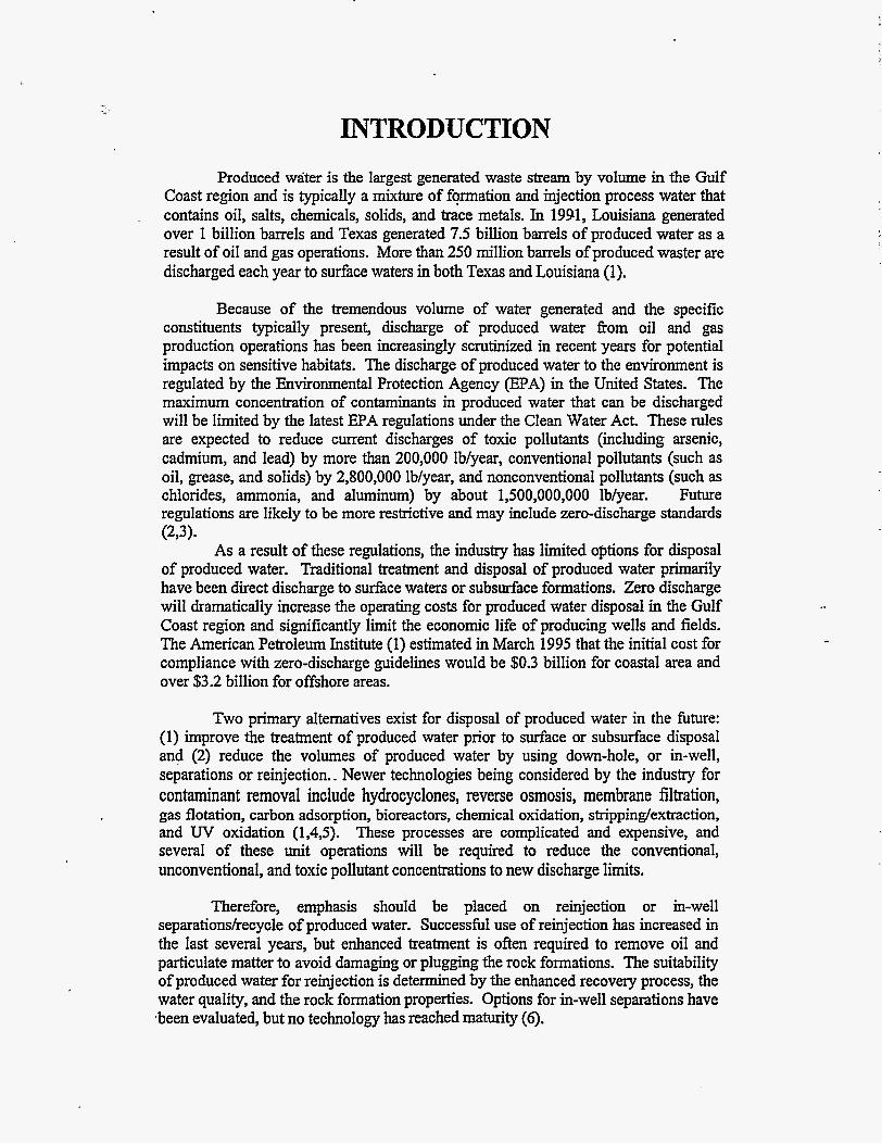
Produced water is the largest generated waste stream by volume in the Gulf Coast region and is typically a mixture of formation and injection process water that contains oil, salts, chemicals, solids, and trace metals. In 1991, Louisiana generated over 1 billion barrels and Texas generated 7.5 billion barrels of produced water as a result of oil and gas operations. More than 250 million barrels of produced waster are discharged each year to surface waters in both Texas and Louisiana (1).
,
Because of the tremendous volume of water generated and the specific constituents typically present, discharge of produced water fiom oil and gas production operations has been increasingly scrutinized in recent years for potential impacts on sensitive habitats. The discharge of produced water to the environment is regulated by the Environmental Protection Agency @PA) in the United States. The maximum concentration of contaminants in produced water that can be discharged will be limited by the latest EPA regulations under the Clean Water Act. These rules are expected to reduce current discharges of toxic pollutants (including arsenic, cadmium, and lead) by more than 200,000 Ib/year, conventional pollutants (such as oil, grease, and solids) by 2,800,000 Ib/year, and nonconventional pollutants (such as chlorides, ammonia, and aluminum) by about 1,500,000,000 Ib/year. Future regulations are likely to be more restrictive and may include zero-discharge standards
As a result of these regulations, the industry has limited options for disposal of produced water. Traditional treatment and disposal of produced water primarily have been direct discharge to surface waters or subsurface formations. Zero discharge will dramatically increase the operating costs for produced water disposal in the Gulf Coast region and significantly limit the economic life of producing wells and fields. The American Petroleum Institute (1) estimated in March 1995 that the initial cost for compliance with zero-discharge guidelines would be $0.3 billion for coastal area and over $3.2 billion for offshore areas.
(2Y3).
Two primary alternatives exist for disposal of produced water in the future: (1) improve the treatment of produced water prior to surface or subsurface disposal and (2) reduce the volumes of produced water by using down-hole, or in-well, separations or reinjection.. Newer technologies being considered by the industry for contaminant removal include hydrocyclones, reverse osmosis, membrane filtration, gas flotation, carbon adsorption, bioreactors, chemical oxidation, strippinglextraction, and W oxidation (1,4,5). These processes are complicated and expensive, and several of these unit operations will be required to reduce the conventional, unconventional, and toxic pollutant concentrations to new discharge limits.
Therefore, emphasis should be placed on reinjection or in-well separations/recycle of produced water. Successful use of reinjection has increased in the last several years, but enhanced treatment is often required to remove oil and particulate matter to avoid damaging or plugging the rock formations. The suitability of produced water for reinjection is determined by the enhanced recovery process, the water quality, and the rock formation properties. Options for in-well separations have *been evaluated, but no technology has reached maturity (6).

,
This project will extend the application of remotely operated separations equipment developed for the nuclear industry to in-well recovery of oil generated by enhanced oil recovery techniques. Centrifugal solvent extraction contactors, originally developed by the Department of Energy for nuclear fuel reprocessing, have been successfully used for surface treatment of produced water and wastewater generated during environmental clean-up operations (7-1 1). Centrifugal contactor units with rotor diameters of 5.5 and 8.4 cm have been previously tested at O W , and a larger unit has been designed for Costqer Industries Nevada, Inc., for these applications. Performance data has shown that centrifugal contactors are capable of separating stable emulsions into “single-phase” streams with generally less than 1% cross-phase contamination. Centrifugal contactors, therefore, have the potential to achieve higher capacity and separations efficiencies that traditional oiywater separator equipment.
The goals of this project are to (a) modify the centrifbgal contactor design for use in down-hole separation of oil and produced water, (b) evaluate the applicability of the modified centrifugal down-hole separator (CDHS) for in-well operations, and (c) evaluate the potential for coupling. the CDHS with recently developed horizontal drilling technology to implement in-situ recycle of produced water for enhanced oil recovery applications (12). The development strategy for accomplishing these goals include (a) conducting bench-scale mixedsettler tests to provide the design parameter for the separator, (b) conducting bench tests with a lab-scale centrifugal unit to determine separation efficiencies with crude oils, (c) designing and operating a larger scale prototype in the lab to examine scale-up and to identify operational problems (i.e., buildup of solids in the rotor), and (d) conducting a full-scale field demonstration of the CDHS system. Figure 1 depicts the concept of installing a centrifugal separator in an oil recovery shaft, with the separated oil being pumped to the surface for recovery and the produced water being recycled through horizontal wells.
The separations device to be considered for in-well applications is comprised of three primary components: a centrifugal separator and two centrifugal pumps. The centrifuge unit itself generates a small hydraulic head, but it would need to be coupled with two centrifugal pumps for deep well applic-ations. The f is t pump would be used to generate sufficient head pressure to pump the recovered oil to the surface and the second to reinject the recovered water. In the conceptual design, the collection rings that receive the separated oil or water phases would feed to one of two pump chambers located below the clarifier rotor unit. The impellers in both pump chambers as well as the rotor of the’separator could be connected to the same drive shaft. The oil pump would be discharged through a pipeline to the surface, while the water would be pumped fiom the bottom of the unit directly into the horizontal wells.
CENTRIFUGAL SEPARATOR BACKGROUND
. ,
Centrifugal contactors of various sizes (fkom 2- to 25-cm rotor-diameter) have been built and operated over the past three decades at the Savannah River Plant, . Argonne National Laboratory, and ORNL for use in solvent extraction processing of production reactor fuel (13). During this period, modifications were made to increase

the overall reliability of the contactor system with operation shifting from paddle- mixed contactors to annular-mixed contactors (14). A schematic diagram of the annular-mixed contactor is presented in Figure 2.
In previous operations with the centrifugal contactor, two immiscible liquids enter at opposite sides of the housing. The more dense phase is typically an aqueous phase,' and the less dense phase is typically an organic phase. The liquids are vigorously mixed by skin fiiction as they flow downward in thi annulus between the housing and the spinning rotor to form an emulsion. Baffles on the bottom of the housing direct the emulsion into the orifice at the bottom of the rotor. A diverter disk directs the mixture to the outer regions of the rotor, where the centrifugal force is greater and radial separation vanes quickly accelerate the mixture to the rotor speed. The aqueous and organic phases are separated by centrifugal force as they flow upward through the rotor, and the separated phases pass over and under a set of circular weirs and are thrown by centrifugal force into their respective collector rings located in the housing. Tangential ports transport the separate effluent phases from the collector rings.
.
The position of the unseparated emulsion band (the aqueous-organic interface) at the top of the rotor must be maintained between the light-phase overflow weir near the center of the rotor and the heavy-phase underflow weir near the periphery of the rotor to prevent cross contamiriation of the aqueous and organic streams. This is accomplished by a combination of proper sizing of the light-phase and heavy-phase weirs ahd the rotational speed of the rotor. At a given rotor speed, the emulsion thickness increases as the throughput increases until the emulsion reaches either the organic weir or the aqueous underflow. When the emulsion reaches the organic weir, aqueous contamination is in the organic stream, and when the emulsion reaches the aqueous weir, organic contamination is in the aqueous stream. When the contamination of each phase reaches 1%, the unit is said to be operating at maximum capacity (14).
*
These units have several characteristics that make them attractive for consideration in down-hole separation of oil and produced water. These include (a) excellent phase separation characteristics and the ability to break stable emulsions; (b) reliability in remote applications with >20,000 hours of operation prior to maintenance; and (c) the ability to handle high volumetric throughput with a very low residence time. However, several modifications must be made to the unit prior to successful use as a CDHS. These include (a) lengthening the rotor to increase the throughput, (b) introducing the oiVwater mixture directly into the bottom of the rotor to limit mixing, (c) overcoming problems associated with the accumulation of solids in the rotor, and (d) connecting the separator to down-hole pumps for pumping the oil to the surface and for reinjecting the produced water. Discussions with representatives from Chevron, Phillips Petroleum, Texaco, Unocal, and the Department of Energy have resulted in the formulation of a set of functional criteria for use in the development of the CDHS. These functional criteria are presented in Table 1.
BENCH-SCALE TESTING AND RESULTS
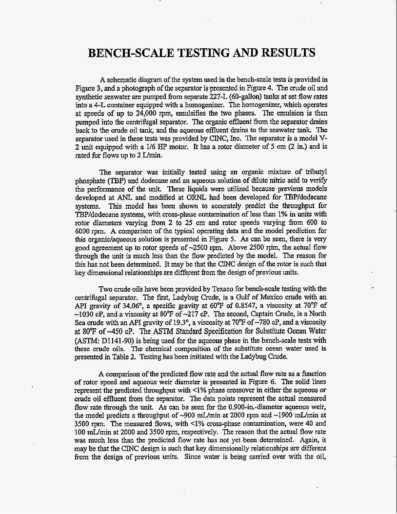
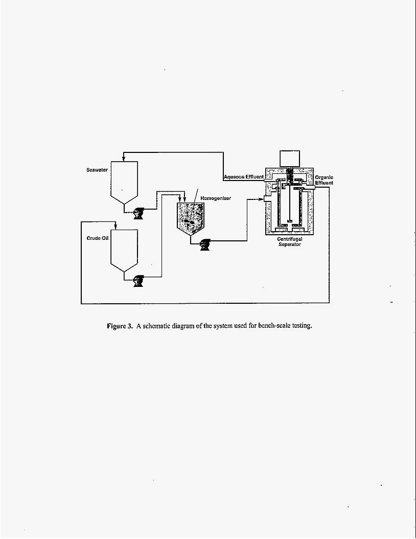
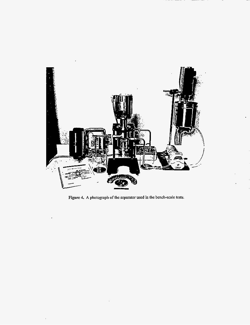
A schematic diagram of the system used in the bench-scale tests is provided in Figure 3, and a photograph of the separator is presented in Figure 4. The crude oil and synthetic seawater are pumped from separate 227-L (60-gallon) tanks at set flow rates into a 4-L container equipped with a homogenizer. The homogenizer, which operates at speeds of up to 24,000 rpm, emulsifies the two phases. The emulsion is then pumped into the centrifugal separator. The organic effluent fiom the separator drains back to the crude oil tank, and the aqueous effluent drains to the seawater tank. The separator used in these tests was provided by ClNC, Inc. The separator is a model V- 2 unit equipped with a 1/6 HP motor. It has a rotor diameter of 5 cm (2 in.) and is rated for flows up to 2 L/min.
The separator was initially tested using an organic mixture of tributyl phosphate (TJ3P) and dodecane and an aqueous solution of dilute nitric acid to verify the performance of the unit. These liquids were utilized because previous models developed at ANL and modified at ORNL had been developed for TBP/dodecane systems. This model has been shown to accurately predict the throughput for TBP/dodecane systems, with cross-phase contamination of less than 1% in units with rotor diameters varying fiom 2 to 25 cm and rotor speeds varying fiom 600 to 6000 rpm. A comparison of the typical operating data and the model prediction for this organic/aqueous solution is presented in Figure 5. As can be seen, there is very good agreement up to rotor speeds of -2500 rpm. Above 2500 @m, the actual flow through the unit is much less than the flow predicted by the model. The reason for this has not been determined. It may be that the CINC design of the rotor is such that key dimensional relationships are different fiom the design of previous units.
Two crude oils have been provided by Texaco for bench-scale testing with the centrifugal separator. The fmt, Ladybug Crude, is a Gulf of Mexico crude with an API gravity of 34.06", a specific gravity at 60°F of 0.8547, a viscosity at 70°F of -1030 cP, and a viscosity at 80°F of -217 cP. The second, Captain Crude, is a North Sea crude with an API gravity of 19.3", a viscosity at 70°F of -780 cP, and a viscosity at 80°F of -450 cP. The ASTM Standard Specification for Substitute Ocean Water (ASTM: D1141-90) is being used for the aqueous phase in the bench-scale tests with these crude oils. The chemical composition of the substitute ocean water used is presented in Table 2. Testing has been initiated with the Ladybug Crude.
A comparison of the predicted flow rate and the actual flow rate as a h c t i o n of rotor speed and aqueous weir diameter is presented in Figure 6. The solid lines represent the predicted throughput with <1% phase crossover in either the aqueous or crude oil effluent fiom the separator. The data points represent the actual measured flow rate through the unit. As can be seen for the 0.900-in.-diameter aqueous weir, the model predicts a throughput of -900 d m i n at 2000 rpm and -1900 d m i n at 3500 rpm. The measured flows, with <1% cross-phase contamination, were 40 and 100 d m i n at 2000 and 3500 rpm, respectively. The reason that the actual flow rate was much less than the predicted flow rate has not yet been determined. Again, it may be that the CINC design is such that key dimensionally relationships are different fiom the design of previous units. Since water is being carried over with the oil,
another possibility is a constriction in the aqueous underflow leading to the aqueous weir.
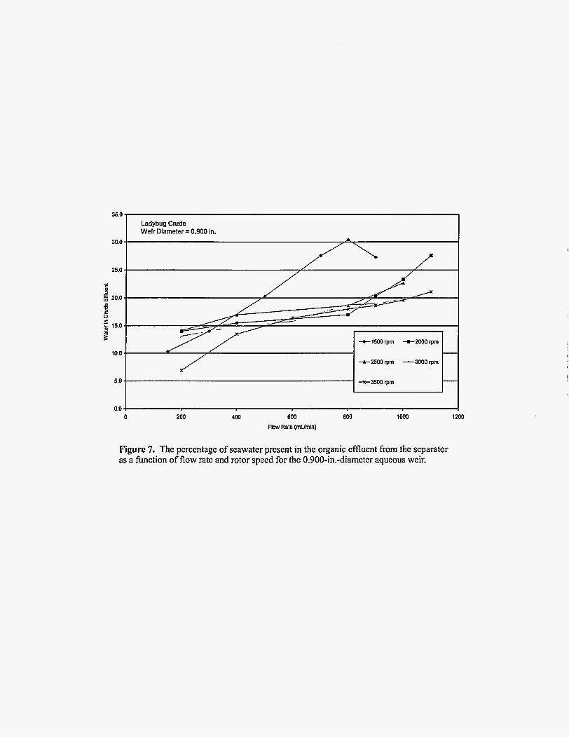
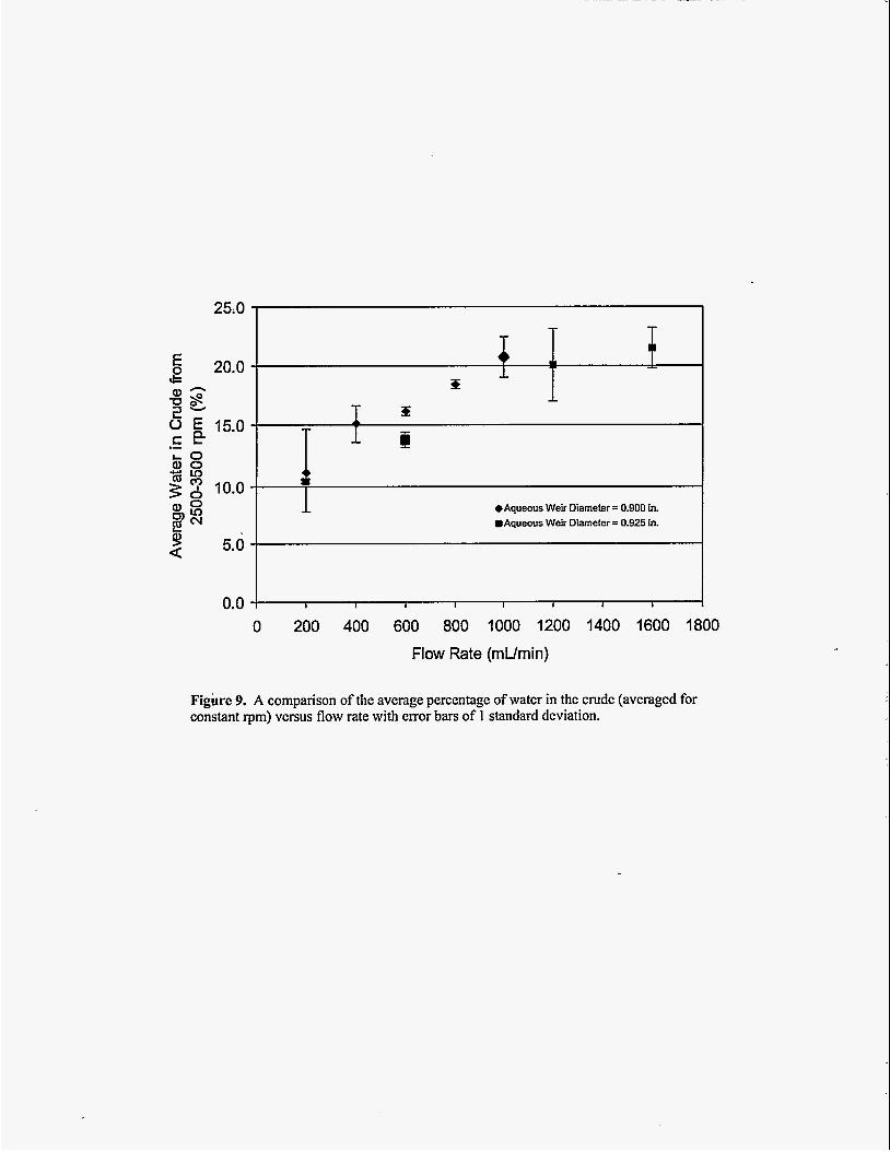
The actual throughput for the separator, with >1% cross-phase contamination, is also presented in Figure 6 for both the 0.900- and 0.925-in.-diameter aqueous weirs. The operational data for those runs with carryover >lo% represent the maximum throughput obtained prior to the crude oil carrying over the aqueous weir (i.e., the crude oil in the aqueous effluent from the separator exceeding >1% by volume). During these runs, the quantity of seawater carried over in the crude effluent increased with throughput. This is presented graphically in Figures 7 and 8, which show the percentage of seawater present in the crude effluent from the separator as a function of flow rate and rotor speed for the 1 1.43- and 1 1.75-mm (0.900- and 0.925-in.)-diameter aqueous weir, respectively. The quantity of seawater in the crude increases with throughput, and there does not seem to be a strong correlation between the rotor speed and the quantity of water present in the crude. A comparison of the average percentage of water in the crude (averaged for constant rpm) versus flow rate with error bars of 1 standard deviation is presented in Figure 9. As can be seen, the percentage of water in the crude is essentially linear with respect to the flow rate for both weirs up to flow rates of 1200 mL/min. Above 1200 mLJmin, the percentage of water in the oil tends to level out in the 20-22% range.
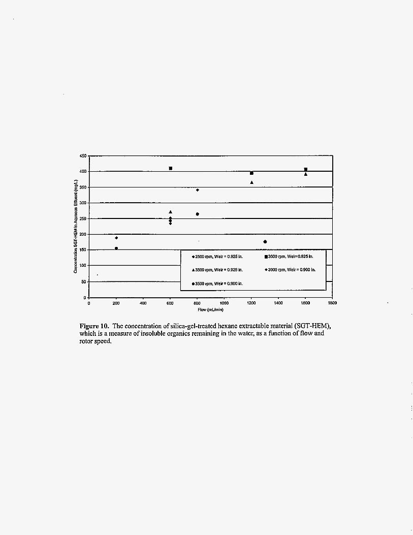
The concentration of silica-gel-treated hexane extractable material (SGT- HEM), which is a measure of the insoluble organics remaining in the water, is presented in Figure 10 as a function of flow and rotor speed. The concentration of SGT-HEM increases with the flow rate and tends to level out at a maximum of -400 mg/L. When comparing the concentration with the fbnctional criteria listed in Table 1, it can be seen that the residual oil is less than the 2000-mgL requirement and is generally in the range of 200-400 mgL. Therefore, the quality of water from these tests appears to be suitable for reinjection.
The hnctional criteria developed by the oil producers participating in the development of the CDHS suggested the use of a separator which would fit into a 6-3/4-in. inside diameter casing. Therefore, the model was run to predict the maximum throughput which could be expected with a 15-cm (6-in.)-diameter rotor as a function of rotor length and speed. The results are presented in Figure 11. By comparing this figure with the functional criteria in Table 1, it appears that the fhctional criterion for a throughput of 2000 to 10,000 barrels per day is achievable with a rotor length of less than 3.7 m (12 feet). However, the data indicates that there may be substantially more water in the crude effluent from the separator than the <1% predicted 'by the model. Additional work is needed to resolve the discrepancies between the model and the actual operational data fiom the Ladybug Crude.
A Centrifuged Downhole Separator (CDHS) is currently being developed at ORNL that will extend the application of remotely operated separations equipment developed for the nuclear industry to in-well recovery of oil with insitu recycle of the produced water. The development strategy used will include (a) bench-scale testing

with crude oils to determine preliminary separation efficiencies and flow, (b) design and laboratory testing of a larger prototype separator that will be utilized to verify scaleup and to identify and overcome operational problems (e.g., buildup of solids in the rotor), and (c) a hll-scale field demonstration of the developed CDHS system. This paper reports on the current status of the development, which is in the bench- scale testing phase.
Bench-scale testing is currently being conducted with a crude oil provided by Texaco and designated as Ladybug Crude. This is a Gulf of Mexico crude with an API gravity of 34.06', a specific gravity at 609; of 0.8547, a viscosity at 70T of -1030 cP, and a viscosity at 80°F of -217 cP. Model predictions for the Ladybug Crude indicate that a separator with a rotor diameter of 15 cm (6 in.) and a length 4 ft could produce -2000 barrels per day at rotor speeds of -1500 to 3500 rpm. For a throughput of 10,000 barrels per day and a 15-cm-diameter rotor, a rotor length of 3.7 m (12 fi) would be required.
The percentage of water remaining in the organic effluent varies with the throughput of the separator. At low flows (-200 a m i n for the bench-scale unit), the crude oil contains -10% water, and near the maximum flow (-1600 mUmin), the crude contains -20% water. The residual oil in the aqueous effluent stream also tended to increase with flow. At low flows, the aqueous stream contained -150-250 g/L, SGT-HEM, and at the maximum flows, the aqueous effluent contained -400 mg/L SGT-HEM. Therefore, the quality of the aqueous effluent fiom the separator appears to be suitable for reinjection.
>
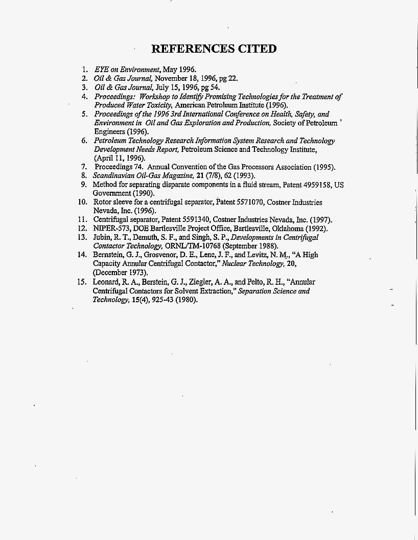
REFERENCES CITED
1. EYE on Environment, May 1996. 2. Oil & Gas Journal, November 18,1996, pg 22. 3. Oil & Gas Journal, July 15,1996, pg 54. 4. Proceedings: Workshop to Identi3 Promising Technologies for the Treatment of
Produced Water Toxicity, American Petroleum Institute (1996). 5. Proceedings of the I996 3rd International Conference on Health, Safety] and
Environment in Oil and Gas Exploration and Production, Society of Petroleum ’ Engineers (1996).
6. Petroleum Technology Research Information System Research and Technology Development Needs Report] Petroleum Science and Technology Institute, (April 11,1996).
7. Proceedings 74. Annual Convention of the Gas Processors Association (1 995). 8. Scandinavian Oil-Gas Magazine, 21 (7/8), 62 (1993). 9. Method for separating disparate components in a fluid stream, Patent 4959158, US
Government (1990). 10. Rotor sleeve for a centrifugal separator, Patent 5571070, Costner Industries
Nevada, Inc. (1996). 11. Centrifugal separator, Patent 5591340, Costner Industries Nevada, Inc. (1997). 12. NIPER-573, DOE Bartlesville Project Ofice, Bartlesville, Oklahoma (1992). 13. Jubin, R. T., Demuth, S. F., and Singh, S. P., Developments in Centnpgal
Contactor Technology, ORMsilM-10768 (September 1988). 14. Bernstein, G. J., Grosvenor, D. E., Lenc, J. F., and Levitz, N. Me., “A High
Capacity Annular Centrifugal Contactor,” Nuclear Technologyl 20, (December 1973).
15. Leonard, R. A,, Berstein, G. J., Ziegler, A. A., and Pelto, R. H., “Annular Centrifugal Contactors for Solvent Extraction,” Separation Science and Technology, 15(4), 925-43 (1980).
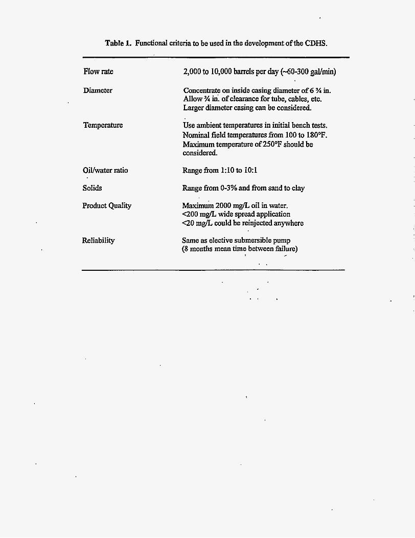
Table 1. Functional criteria to be used in the development of the CDHS.
Flow rate
Diameter
Temperature
OiVwater ratio
~
2,000 to 10,000 barrels per day (-60-300 gal/min)
Concentrate on inside casing diameter of 6 % in. Allow % in: of clearance for tube, cables, etc. Larger diameter casing can be considered.
Use ambient temperatures in initial bench tests. Nominal field temperatures eom 100 to 180°F. Maximum temperature of 25OoF should be considered.
Range from 1:lO to 1O:l
Solids Range from 0-3% and from sand to clay
Product Quality ~ a x i m u m 2000 mg/L oil in water. G O O mg/L wide spread application <20 mgL could be reinjected anywhere
Reliability Same as elective submersible pump (8 months mean time between fXure)
I #
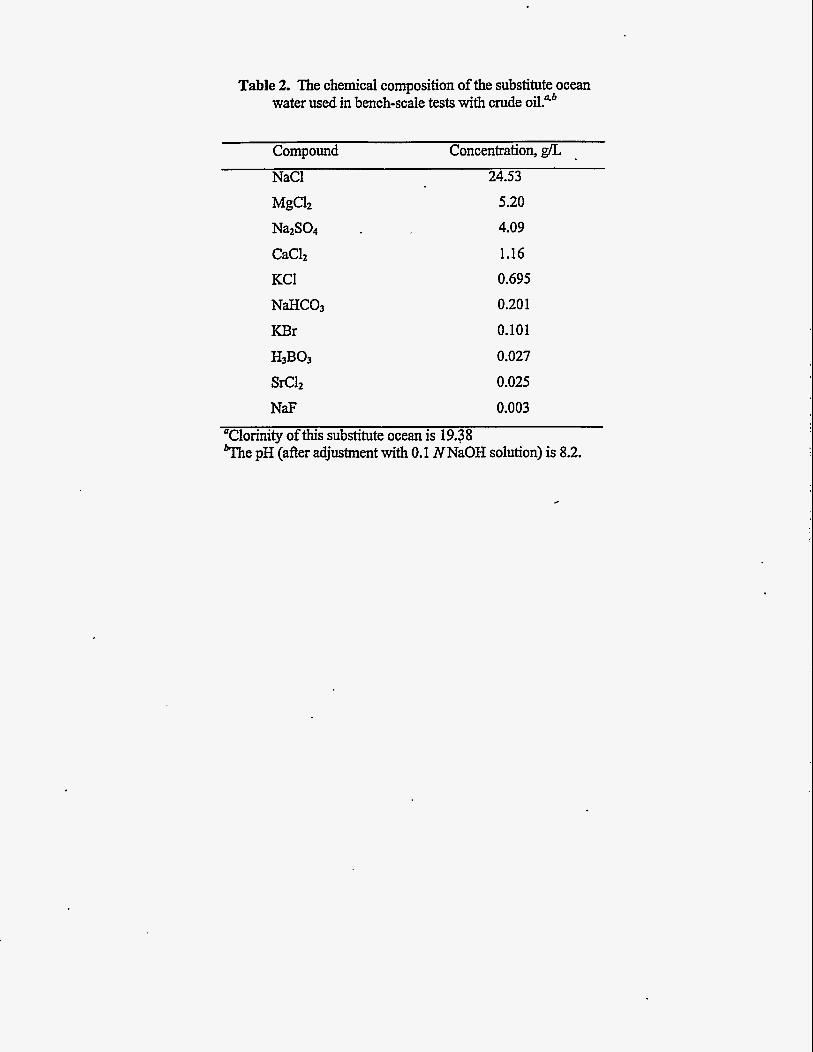
Table 2. The chemical composition of the substitute ocean water used in bench-scale tests with crude oil."b
Compound Concentration, g/L NaCl 24.53
5.20
4.09
1.16
0.695
0.201
0.101
0.027
0.025
NaF 0.003
"Clorinity of this substitute ocean is 19.38 %e pH (after adjustment with 0.1 NNaOH solution) is 8.2.

OWL DWG 97C-124
WATER FLOODING SEPARATOR
Figure 1. A conccptual drawing for thc installation of a centrifugal separator in an oil rccovcry shaft, with the scparatcd oil bcihg pumped to thc surfacc for rccovcry and the produccd water being recycled through horizontal wclls.

ORNL DWG 98C-68
Drive Motor
n Heavy-Phase Weir
Heavy- or Mixed-
Separation Vanes (4) Diverter Disk Annular Mixing
Rotor Bottom Inlet Vanes
Figure 2. A schematic drawing of the annular-mixed contactor.
Seawater
omogenizer
f
Centrifugal Separator
Figure 3. A schematic diagram of the system uscd for bench-scale testing.

1600
-
- 1400 -Model (Weir = 0.925 in.)
0 Data (Weir = 0.925 in.) 1200
1000
.- E
2 800 - 2 G
600
400
200
/
/ " I
0 500 1000 1500 2000 2500 3000 3500 4000
rpm
Figure 5. A comparison of the operating data and model predictions for the V2 separator while processing an organic solution of tributyl phosphate (TBP) and dodccanc and a dilute nitric acid aqueous solution.

m
P 1500
3
500
0 a rn m
0 500 lo00 1500 2wo wx) 3wo 3500 4MM
Rotor Speed (RPM)
Figurc 6. A comparison of thc prcdictcd flow ratc and the actual flow ratc as a function of rotor speed and aqucous weir diamctcr.
Ladybug Crude I Weir Diameter = 0.900 in.
0 200 4w 600 800 1000 1200
Flow Rale (mumin)
Figure 7. The pcrccntage of scawatcr prcsent in thc organic effluent from the separator as a hnction of flow rate and rotor speed for thc 0.900-in.-diamctcr aqueous wcir.

Ladybug Crude Weir Diameter = 0.925 in.
- -
8 - + 1500 rpm +2000 rpm
c 0 -
+-25M)rpm -30OOrpm -
+3500 rpm 5.0 - -
0.0 i 1600 1800 21 ‘ 0 200 400 600 800 1000 12w 1400
Flow Rate (mumin)
Figure 8. The percentage of seawater present in the organic effluent from the separator as a function of flow rate and rotor speed for thc 0.925-in.-diamctcr aqueous weir.
E 20.0 a,- 7Js 2 - 0 E 15.0 .- re-
0.0
T T r
1 eAqueous Weir Diameter = 0.900 in. .Aqueous Weir Diameter = 0.925 in.
0 200 400 600 800 1000 1200 1400 1600 1800
Flow Rate (mumin)
Figurc 9. A comparison of the average percentage of water in thc crude (avcragcd for constant rpm) versus flow rate with error bars of 1 standard deviation.
YI --- n
P $ 2 5 0 -
$ 200-
::
- c I
I-
6 150-
p loo-.
50.
1 .
0 200 400 600 8 W 1000 1200 1400 1600 law Flow (mumin)
e A A
t
+ 0
e2500 rpm. Weir = 0.925 In.
A3500 rpm. Weir = 0.925 in.
0 3500 rpm. Weir = 0.900 in.
3000 rpm. Wei~O.925 in.
e3wO rpm. Weir = 0.900 in. -
- -
Figurc 10. The concentration of silica-gel-treated hexane extractable material (SGT-HEM), which is a measure of insoluble organics remaining in the watcr, as a function of flow and rotor speed.

I 2 4 6 8 i o 12 14 16 18 0
Rolor Lenglh (fl)
Figure 11. The maximum throughput that could be expected with a 15-cm (6-in.)-diameter rotor as a function of rotor length and speed from modcl predictions.