Embed Size (px)
Citation preview
TECHNOLOGY READINESS
OF ADVANCED
COAL-BASED POWER
GENERATION SYSTEMS
DR LESLEY SLOSS
C CC/ 2 9 2 F E B R U A R Y 2 0 1 9

I E A C L E A N C OA L C E N T R E A P S L E Y H OU S E , 1 7 6 U P P E R R I C H M ON D R OA D
L ON D ON , S W 1 5 2 S H U N I T E D K I N G D OM
+4 4 [ 0 ] 2 0 3 9 0 5 3 8 7 0
W W W . I E A - C OA L . ORG
TE CHNO LOG Y READINESS
O F ADVANCED
COAL-BASE D POWER
GE NERATIO N S YSTEMS

I E A C L E A N C O A L C E N T R E – T E C H N O L O G Y R E A D I N E S S O F A D V A N C E D C O A L - B A S E D P O W E R
G E N E R A T I O N S Y S T E M S
3
AUTHOR DR LE SL E Y SL OSS
IE A CCC R EPOR T NUMBER C CC/29 2
ISBN 9 78–9 2–9 029–61 5-7
© IEA CLEAN COAL CE N TRE
PUBLICATION DATE FE BRU ARY 201 9

I E A C L E A N C O A L C E N T R E – T E C H N O L O G Y R E A D I N E S S O F A D V A N C E D C O A L - B A S E D P O W E R
G E N E R A T I O N S Y S T E M S
4
P R E F A C E
This report has been produced by the IEA Clean Coal Centre and is based on a survey and analysis of
published literature, and on information gathered in discussions with interested organisations and
individuals. Their assistance is gratefully acknowledged. It should be understood that the views expressed
in this report are our own, and are not necessarily shared by those who supplied the information, nor by
our member organisations.
The IEA Clean Coal Centre was established in 1975 and has contracting parties and sponsors from:
Australia, China, the European Commission, Germany, India, Italy, Japan, Poland, Russia, South Africa,
Thailand, the UAE, the UK and the USA.
The overall objective of the IEA Clean Coal Centre is to continue to provide our members, the IEA Working
Party on Fossil Fuels and other interested parties with independent information and analysis on all
coal-related trends compatible with the UN Sustainable Development Goals. We consider all aspects of
coal production, transport, processing and utilisation, within the rationale for balancing security of supply,
affordability and environmental issues. These include efficiency improvements, lowering greenhouse and
non-greenhouse gas emissions, reducing water stress, financial resourcing, market issues, technology
development and deployment, ensuring poverty alleviation through universal access to electricity,
sustainability, and social licence to operate. Our operating framework is designed to identify and publicise
the best practice in every aspect of the coal production and utilisation chain, so helping to significantly
reduce any unwanted impacts on health, the environment and climate, to ensure the wellbeing of societies
worldwide.
The IEA Clean Coal Centre is organised under the auspices of the International Energy Agency (IEA) but
is functionally and legally autonomous. Views, findings and publications of the IEA Clean Coal Centre do
not necessarily represent the views or policies of the IEA Secretariat or its individual member countries.
Neither IEA Clean Coal Centre nor any of its employees nor any supporting country or organisation, nor
any employee or contractor of IEA Clean Coal Centre, makes any warranty, expressed or implied, or
assumes any legal liability or responsibility for the accuracy, completeness or usefulness of any
information, apparatus, product or process disclosed, or represents that its use would not infringe
privately-owned rights.

I E A C L E A N C O A L C E N T R E – T E C H N O L O G Y R E A D I N E S S O F A D V A N C E D C O A L - B A S E D P O W E R
G E N E R A T I O N S Y S T E M S
5
A B S T R A C T
This report summarises state-of-the-art coal-based power technologies which are not fully yet
commercial, focusing on where these systems could be most suited, such as regions with challenging fuel
resources/characteristics, capacity needs, and water availability. The technologies studied are advanced
ultrasupercritical combustion (AUSC), integrated gasification combined cycles (IGCC), polygeneration,
oxyfuel combustion, supercritical CO2 systems, and hybrid systems. A summary is provided of the current
status of each advanced concept in relation to full-scale commercial application. The report identifies the
technology gaps that need to be addressed for successful deployment along with an outline of the specific
research, testing or demonstration which is required to address each gap.
All of the technologies reviewed in this report need further investment in terms of time and resources to
be considered fully market-ready. In terms of proximity to commercialisation, IGCC leads the way with
several full-scale demonstration plants completed and more under construction. Advancement of
polygeneration, while technically achievable, will depend on suitable local markets. AUSC is a step up in
pressure and temperature from available USC systems. However, advances in metal alloys are required to
ensure these plants are technically viable. For oxyfuel combustion to move beyond small-scale
demonstration, there will need to be technical advances and increased assurance that the technology can
rival standard pulverised coal-fired systems with carbon capture in terms of power output and cost.
Supercritical CO2 systems are relatively new concepts but are moving towards demonstration scale faster
than most other advanced coal-based technologies. Stationary fuel cells are expensive but commercial,
although not yet running on coal. However, distinct advances in theoretical and materials chemistry will
need to be made before coal-based fuel cells reach the market. The success of hybrid systems, combining
nuclear and renewable sources with coal plants, will be situation specific and could be useful in areas with
suitable infrastructure and commercial support.
The report summarises the technological advances required to move new coal-based technologies to
commercial scale but also considers non-technical factors such as funding and national policies which can
ultimately determine where these technologies may succeed.

I E A C L E A N C O A L C E N T R E – T E C H N O L O G Y R E A D I N E S S O F A D V A N C E D C O A L - B A S E D P O W E R
G E N E R A T I O N S Y S T E M S
6
A C R O N Y M S A N D A B B R E V I A T I O N S
ASTM American Society of Testing and Materials
ASU air separation unit
AUSC advanced ultrasupercritical
CCS carbon capture and storage
CCU carbon capture and utilisation
CFBC circulating fluidised bed combustion
CFC carbon fuel cells
CHP combined heat and power
CLC chemical looping combustion
CLOU chemical looping with oxygen uncoupling
CPU CO2 purification unit
CSIRO Commonwealth Scientific and Industrial Research Organisation, Australia
CSP concentrated solar power
CURC Coal Utilisation Research Council, USA
DCFC direct carbon fuel cell
DECC Department of Energy and Climate Change, UK
DOE Department of Energy, USA
EAGLE Coal Energy Application for Gas, Liquid and Electricity
EDF Électricité de France
EERC Energy and Environmental Research Centre, USA
EPA Environmental Protection Agency, USA
EPRI Electric Power Research Institute, USA
FC fuel cells
FCH JU European Fuel Cell and Hydrogen Joint Undertaking Programme
GTFC gas turbine fuel cell
HECA Hydrogen Energy California
HELE high efficiency low emissions
HHV higher heating value
HIPPS high performance power generating systems
IEA International Energy Agency
IEA CCC IEA Clean Coal Centre
IGTC integrated gasification triple cycle
IGCC integrated gasification combined cycle
IGFC integrated gasification fuel cell
IST Integrated System Test, USA
KAIST Korea Advanced Institute of Science & Technology
KIER Korea Institute of Energy Research
LCOE levelised cost of electricity
LCOP levelised cost of polygeneration
LHV lower heating value

I E A C L E A N C O A L C E N T R E – T E C H N O L O G Y R E A D I N E S S O F A D V A N C E D C O A L - B A S E D P O W E R
G E N E R A T I O N S Y S T E M S
7
LNG liquified natural gas
MCFC molten carbonate fuel cell
MES multifunctional energy system
MHD magnetohydrodynamic
MHIS Mitsubishi Heavy Industries Ltd
MHPS Mitsubishi Heavy Power Sector
MOU Memorandum of Understanding
MWe megawatt electric
MWth megawatt thermal
NEDO New Energy and Industrial Technology Development Organisation, Japan
NETL National Energy Technology Laboratory, USA
NTPC National Thermal Power Corporation, India
OCDO Ohio Coal Development Office, USA
PC pulverised coal combustion
psig pounds per square inch gauge
PV photovoltaic
R&D research and development
SC supercritical
SCIEL sCO2 Integral Experimentation Loop, South Korea
sCO2 supercritical carbon dioxide
SECA Solid-State Energy Conversion Alliance, USA
SNG synthetic natural gas
SNL Sandia National Lab, USA
SOFC solid oxide fuel cell
STEP Supercritical Transformation Electric Power, USA
SWRI Southwest Research Institute, USA
TCEP Texas Clean Energy Project, USA
TITech Tokyo Institute of Technology (Japan)
TRL technology readiness level
UCG underground coal gasification
UNFCCC United Nations Framework Convention on Climate Change
USC ultrasupercritical
US CEC US-China Energy Centre

I E A C L E A N C O A L C E N T R E – T E C H N O L O G Y R E A D I N E S S O F A D V A N C E D C O A L - B A S E D P O W E R
G E N E R A T I O N S Y S T E M S
8
C O N T E N T S
PREFACE 4
ABST RACT 5
ACRONYMS AND ABBREVI AT IONS 6
CONTENT S 8
LIST OF FIGU RES 1 0
LIST OF T ABLES 11
EXECUTIVE SU MMARY 1 2
1 INTRODUCT ION 1 5
2 ADVANCED ULT RASUPERC RIT ICAL (AU SC) GENER AT ION 1 8
2.1 Principles of the technology 18
2.2 Current deployment 19
2.3 Future development 21
2.4 Challenges 22
2.4.1 Technology requirements 23
2.4.2 Economics 26
2.4.3 Barriers to be addressed 26
2.5 Comments 27
3 INTEGRAT ED GASIFICAT ION COMBINED CYCLE ( IGCC) 28
3.1 Principles of the technology 28
3.2 Current deployment 31
3.3 Future development 35
3.4 Challenges 37 3.4.1 Technology requirements 38
3.4.2 Economics 39
3.4.3 Barriers to be addressed 40
3.5 Comments 41
4 POLYGENERATION 4 3
4.1 Principles of the technology 43 4.2 Current deployment 44
4.3 Future development 45
4.3.1 Europe 45
4.3.2 USA 50
4.3.3 China 52
4.3.4 Other Asian countries 53 4.4 Challenges 54
4.4.1 Technology requirements 54
4.4.2 Economics 54
4.4.3 Barriers to be addressed 56
4.5 Comments 57
I E A C L E A N C O A L C E N T R E – T E C H N O L O G Y R E A D I N E S S O F A D V A N C E D C O A L - B A S E D P O W E R
G E N E R A T I O N S Y S T E M S
9
5 OXYFUEL COMBUST ION 58
5.1 Principles of the technology 58
5.2 Current deployment 59
5.3 Future development 62
5.4 Challenges 62
5.4.1 Technology 62
5.4.2 Economics 63
5.4.3 Barriers to be addressed 65 5.5 Comments 65
6 SU PERCRIT ICAL CO 2 AND THE ALLAM CYCLE 6 7
6.1 Principles of the technology 67
6.2 Current deployment 71
6.3 Future development 73
6.4 Challenges 73 6.4.1 Technology 73
6.4.2 Economics 75
6.4.3 Barriers to be addressed 75
6.5 Comments 76
7 STATIONARY FU EL CELL S 78
7.1 Principles of the technology 78
7.2 Current deployment 80
7.3 Future development 81
7.4 Challenges 83
7.4.1 Technology 83
7.4.2 Economics 85
7.4.3 Barriers to be addressed 86
7.5 Comments 86
8 OT HER SYST EMS 88
8.1 Chemical looping 88
8.2 Hybrid systems 90
8.3 Comments 96
9 CONCLUSIONS 9 8
1 0 REFERENCES 1 04

I E A C L E A N C O A L C E N T R E – T E C H N O L O G Y R E A D I N E S S O F A D V A N C E D C O A L - B A S E D P O W E R
G E N E R A T I O N S Y S T E M S
10
L I S T O F F I G U R E S
Figure 1 Development of clean coal technology by NEDO, Japan 16
Figure 2 ‘Valley of Death’ curve for emerging technologies 17
Figure 3 Reducing CO2 emissions through efficiency improvements in coal-fired power stations 18
Figure 4 Technology readiness levels 25
Figure 5 CURC-EPRI Roadmap for coal technology development 25
Figure 6 Flow chart of IGCC process 29
Figure 7 Roadmap of power generation technology development in Japan 30
Figure 8 Coal types which can be used in EAGLE gasification systems 30
Figure 9 Developments in coal gasification 41
Figure 10 Polygeneration from electric power to hydrogen to chemicals (the Texas Clean
Energy Project) 44
Figure 11 FABIENE project plan, Germany 47
Figure 12 Emissions from the FABIENE project options 48
Figure 13 Economics of the FABIENE project 49
Figure 14 Sankey diagram of a co-pyrolysis case study (60% coal to biomass) 50
Figure 15 Oxyfuel combustion for coal fired power plant with CCS 58
Figure 16 Breakdown of oxyfuel plant costs 64
Figure 17 Indirect and direct sCO2 cycles 67
Figure 18 Allam Cycle, basic process diagram 69
Figure 19 The coal-fired Allam Cycle 70
Figure 20 Comparison of optimised coal Allam Cycle configurations 71
Figure 21 US DOE NETL STEP Program 74
Figure 22 Allam Cycle development pathway 76
Figure 23 Diagram of a SOFC 79
Figure 24 Coal-based pressurised IGFC system 82
Figure 25 R&D map for NETL SOFC development 83
Figure 26 Different contact modes of solid carbon with the anode in DCFC systems 84
Figure 27 Chemical looping process 88
Figure 28 Potential hybrid polygeneration systems 92
Figure 29 Feasible implementation of various hybrid systems based on the geographical
distribution of energy resources 95
Figure 30 Status of deployment of advanced coal-based power systems 98
I E A C L E A N C O A L C E N T R E – T E C H N O L O G Y R E A D I N E S S O F A D V A N C E D C O A L - B A S E D P O W E R
G E N E R A T I O N S Y S T E M S
11
L I S T O F T A B L E S
Table 1 Advanced steam cycle conditions 19
Table 2 Material types 23
Table 3 Material selection and consideration for AUSC systems 24
Table 4 Coal IGCC projects operational or under construction in 2017 32
Table 5 Coal IGCC power projects at the planning stage 36
Table 6 Comparison of IGCC-polygeneration 46
Table 7 Economic comparison of 1000 MW IGCC and polygeneration systems 47
Table 8 Pilot- and demonstration-scale oxycombustion plants 60
Table 9 Coal type, gasification process and operation selected for Allam Cycle analysis 70
Table 10 Summary of status of emerging coal power technologies 101

I E A C L E A N C O A L C E N T R E – T E C H N O L O G Y R E A D I N E S S O F A D V A N C E D C O A L - B A S E D P O W E R
G E N E R A T I O N S Y S T E M S
12
E X E C U T I V E S U M M A R Y
The Paris Agreement aims to limit the increase in global temperature to 1.5°C. Since coal is the most
carbon-intensive of all fossil fuels, many countries plan to remove it from their energy mix. However, coal
offers energy reliability and affordability in many growing and emerging regions and so its use must
continue to advance through HELE status (high efficiency low emissions) towards becoming a
zero-emissions option. The figure below shows the approximate stage of development of several advanced
coal-based power systems on the curve from theoretical design through to practical readiness. There are
two major hurdles between conception and commercialisation: the first is the transition from theory to
research scale (laboratory- or small-scale pilot); the second is the move from pilot- to full-scale
demonstration. Research-scale projects cost in the order of US$1–2 million and pilot plants are at least an
order of magnitude more expensive. Many new technologies do not make it to full scale. And so,
investment is perceived to be risky and often relies heavily on government support. Even then, not all
systems will pass both hurdles.
Status of deployment of advanced coal-based power systems
THE CONTENDING TECHNOLOGIES
New conventional, subcritical, pulverised coal fired power plants are limited in terms of achievable
efficiency, to an average of around 37%. Ultrasupercritical (USC) plants use innovative materials to allow
higher temperatures and pressures and thus greater efficiencies. The focus is now on developing advanced
ultrasupercritical (AUSC) power plants which will nudge efficiencies past 45% towards 50% (LHV).

I E A C L E A N C O A L C E N T R E – T E C H N O L O G Y R E A D I N E S S O F A D V A N C E D C O A L - B A S E D P O W E R
G E N E R A T I O N S Y S T E M S
13
Integrated gasification combined cycle (IGCC) plants produce power from both the heat of gasification
of coal and from combustion of the syngas produced. IGCC systems are expensive to build and, although
they offer the potential for cost-effective carbon capture and utilisation or storage (CCUS), their
advantage over USC and AUSC plants relies heavily on the monetisation of this advantage. The handful of
full-scale IGCC projects in Japan and China will likely determine the feasibility of this technology in
practice. Next-stage development will see the syngas from IGCC used in a fuel cell (IGFC).
Combustion systems which use O2 rather than air for combustion (oxycombustion) offer advantages for
CCUS since the flue gas, once scrubbed, is relatively pure CO2. However, like IGCC, the extra expense of
this approach is only economically sensible if there is remuneration through carbon credits or CO2 sales.
Supercritical CO2 systems (sCO2) take advantage of the fluid dynamics of sCO2 to operate turbines more
efficiently than steam. This sCO2 can be in closed, indirect, cycles, or the sCO2 could be produced from
cleaned oxyfuel combustion gases. The Allam Cycle is an sCO2 system currently being tested in Texas on
gas, which could lift the efficiency of combustion systems by several per cent whilst also producing a clean
CO2 flue gas. The high efficiency, small size and simple layout of sCO2 power cycles coupled with other
technology attributes could result in potentially large reductions in capital and fuel costs, and decreased
greenhouse gas emissions. The sCO2 cycle therefore facilitates CCUS but requires there to be a demand
for it.
Polygeneration systems can produce either chemicals or electricity from gasified coal or can produce
both simultaneously. In practice, the extra expense and complexity of these plants can be off-putting to
investors who are likely to focus on whichever product will give the most revenue in the shortest period.
Hybrid systems, such as plants which use solar power to preheat intake water for coal plants, are
technically feasible. The challenge is to make them practical and affordable and this is likely to be
case-specific.
Many of the technologies discussed will benefit from developments in advanced materials and in materials
handling (production, fabrication and welding). A new supply chain of components will need to be created
to allow these systems to be rolled out in any quantity. All these systems will require further support and
funding to ensure they make it to the peak of the development curve (see figure above).
Critical factors for success
The sheer scale of advanced coal-based projects may make banks and insurance agencies reluctant to be
involved in their finance. As the number of advanced coal plants grows, however, this investment risk will
reduce as the uncertainties are resolved and the knowledge and experience increase. There are several

I E A C L E A N C O A L C E N T R E – T E C H N O L O G Y R E A D I N E S S O F A D V A N C E D C O A L - B A S E D P O W E R
G E N E R A T I O N S Y S T E M S
14
factors which could create the impetus needed to move some of these systems from development into
deployment:
• emission standards which promote investment in ultra-clean baseload power systems;
• CO2 credits or other financial advantages for systems which facilitate commercial carbon capture; and
• financial rewards for providing clean, flexible baseload power as a back-up to intermittent renewable
energy systems.
• Coal could offer almost zero emission power in the future but, to achieve this goal, significant
investment is required to carry innovative new technologies from theory into practice.

I N T R O D U C T I O N
I E A C L E A N C O A L C E N T R E – T E C H N O L O G Y R E A D I N E S S O F A D V A N C E D C O A L - B A S E D P O W E R
G E N E R A T I O N S Y S T E M S
15
1 I N T R O D U C T I O N
According to Wolfersdorf and Meyer (2017), there are six main factors affecting the energy sector
and the success of technologies within it:
• the substitution of crude oil with other fuels to reduce import dependencies (promoting
polygeneration and coal-to-x systems);
• substitution of LNG (liquid natural gas) imports for economic reasons (promoting
polygeneration and coal-to-x systems);
• increasing use of low-quality coals in emerging economies;
• increasing shale gas utilisation (fuel competition);
• further growth of coal use in countries such as China; and
• sustained efforts to reduce CO2 emissions by carbon capture and storage or utilisation (CCS and
CCU).
The success of current and future energy projects will largely be determined by how they fit into this
prospective new energy mix. For the most part, those systems which offer flexibility, reliability, and
the use of indigenous fuel supplies whilst helping to mitigate CO2 emissions, will be at a distinct
advantage. There are therefore new technologies emerging which propose to allow the use of coal,
frequently low-quality, to produce flexible electricity and/or alternative chemical products, often with
the capacity for CCU/CCS. However, whilst these technologies would indeed be in demand, if
available, many are at the developmental stage and, as such, may be considered expensive or risky
investments.
This report concentrates on the latest developments in advanced, full-scale coal-fired boiler design
and related coal-based energy systems. It focuses on the innovations but also the practical limitations
of these new technologies, such as coal type, plant size and scale, and resource requirements. An
indication is given of where such technologies would be best suited, for example in areas with limited
water resources. The report also considers the issues that need to be addressed before such
technologies become mainstream, highlighting requirements for further investment and full-scale
demonstrations.
ALTHOUGH FEW OF THE TECHNOLOGIES DISCUSSED IN
THIS REPORT ARE FULL Y COMMERCIALISED, THEY
FEATURE IN THE POWER ROADMAPS OF SEVERAL
ORGANISATIONS AND CO UNTRIES

I N T R O D U C T I O N
I E A C L E A N C O A L C E N T R E – T E C H N O L O G Y R E A D I N E S S O F A D V A N C E D C O A L - B A S E D P O W E R
G E N E R A T I O N S Y S T E M S
16
The predicted development of clean coal technology in Japan, according to the New Energy and
Industrial Development Organisation (NEDO) is shown in Figure 1. Integrated gasification combined
cycle (IGCC) has been operational in Japan since 2006 and integrated gasification fuel cell (IGFC)
projects were initiated in 2017. Further IGCC developments, such as entrained flow, oxyfuel IGCC,
chemical looping and CO2 recovery, are not expected until 2030 at the earliest, and yet they appear as
definitive targets within the roadmap of Japan’s energy system. These, and other new coal combustion
technologies, are evaluated as part of this report.
Figure 1 Development of clean coal technology by NEDO, Japan (Yasui, 2014)
What is clear from Figure 1 is that Japan sees coal as an important part of the energy mix for the next
few decades. It is also clear that high efficiency, low emission (HELE), gasification systems are the
main priority rather than conventional combustion-based systems.
This report summarises the emerging coal-based technologies which are the focus of research and
development (R&D) in many countries. Some of them are close to commercial deployment whereas
others are still at the developmental stage. Figure 2 shows the standard ‘Valley of Death’ curve for
emerging new projects. There are two potential points in the development of a new technology where
it can fail: the first is just after the laboratory-scale tests, when the move to the larger pilot-scale phase
can prove too problematic for the developers or too risky for investors; the second is the step up from
pilot scale to demonstration scale, again a period where the technological or economic risks may prove
too high.

I N T R O D U C T I O N
I E A C L E A N C O A L C E N T R E – T E C H N O L O G Y R E A D I N E S S O F A D V A N C E D C O A L - B A S E D P O W E R
G E N E R A T I O N S Y S T E M S
17
Figure 2 ‘Valley of Death’ curve for emerging technologies (GCCSI, 2018)
This report reviews several new and emerging coal combustion-based power systems – Advanced
ultrasupercritical (AUSC) (Chapter 2), IGCC (Chapter 3); polygeneration (Chapter 4); oxyfuel
combustion (Chapter 5); supercritical CO2 (sCO2) (Chapter 6); and several more conceptual systems
such as chemical looping, fuel cells and hybrid systems (Chapter 7). Each technology has been the
focus of recent detailed reports from the IEA Clean Coal Centre (IEA CCC). This overarching report
gives a brief review of each, focusing more on their status of development, the technological advances
required to move them to commercial scale, and an indication of how and where these technologies
are most likely to succeed.

A D V A N C E D U L T R A S U P E R C R I T I C A L ( A U S C ) G E N E R A T I O N
I E A C L E A N C O A L C E N T R E – T E C H N O L O G Y R E A D I N E S S O F A D V A N C E D C O A L - B A S E D P O W E R
G E N E R A T I O N S Y S T E M S
18
2 A D V A N C E D U L T R A S U P E R C R I T I C A L ( A U S C )
G E N E R A T I O N
Conventional subcritical pulverised coal-fired plants are now considered dated and inefficient,
reaching a maximum of around 39% efficiency (lower heating value, LHV). The coal power sector is
moving towards systems which can operate at higher temperatures and pressures to produce
significantly more power from the same volume of coal, while simultaneously releasing fewer
emissions to the atmosphere. Figure 3 shows the increase in plant efficiency, including the current
global average of 35% (HHV net, equivalent to around 37% LHV net), and up through supercritical
(SC) to current state of the art ultrasupercritical (USC) efficiency of 47.8% (demonstrated at the
Waigaoqiao plant in China). The chart also shows the projected continued increase in efficiency as the
sector moves towards advanced USC (AUSC). At the same time, the figure highlights the decrease in
CO2 emissions for coal-fired power plants from subcritical units through SC and USC to AUSC.
Figure 3 Reducing CO2 emissions through efficiency improvements in coal-fired power stations
(IEA CCC, 2018)
The reduction in CO2 emissions between subcritical coal-fired plants, and state-of-the-art USC is
substantial – around 20–25%, and AUSC systems could lower CO2 emissions further. Reducing coal
use and moving to more efficient coal systems is an important part of the United Nations Framework
Convention on Climate Change (UNFCCC) plan to reduce global emissions of CO2 (WEC, 2016).
2.1 PRINCIPLES OF THE TECHNOLOGY
Supercritical boilers have higher efficiencies than subcritical coal combustion due to increased steam
parameters. In supercritical systems, the steam reaches a supercritical state rather than boiling. The
improved supercritical steam cycles involve higher temperatures and higher pressures which result in
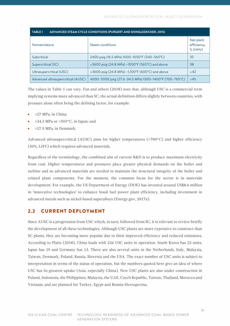
high efficiencies and lower coal consumption, as shown in Table 1 (Purgert and Shingledecker, 2015).
A D V A N C E D U L T R A S U P E R C R I T I C A L ( A U S C ) G E N E R A T I O N
I E A C L E A N C O A L C E N T R E – T E C H N O L O G Y R E A D I N E S S O F A D V A N C E D C O A L - B A S E D P O W E R
G E N E R A T I O N S Y S T E M S
19
TABLE 1 ADVANCED STEAM CYCLE CONDITIONS (PURGERT AND SHINGLEDECKER, 2015)
Nomenclature Steam conditions
Net plant
efficiency,
% (HHV)
Subcritical 2400 psig (16.5 MPa) 1000–1050°F (540–565°C) 35
Supercritical (SC) >3600 psig (24.8 MPa) ~1050°F (565°C) and above 38
Ultrasupercritical (USC) >3600 psig (24.8 MPa) ~1,100°F (600°C) and above >42
Advanced ultrasupercritical (AUSC) 4000–5000 psig (27.6–34.5 MPa) 1300–1400°F (700–760°C) >45
The values in Table 1 can vary. Fan and others (2018) note that, although USC is a commercial term
implying systems more advanced than SC, the actual definition differs slightly between countries, with
pressure alone often being the defining factor, for example:
• >27 MPa, in China;
• >24.2 MPa or >593°C, in Japan; and
• >27.5 MPa, in Denmark.
Advanced ultrasupercritical (AUSC) aims for higher temperatures (>700°C) and higher efficiency
(50%, LHV) which requires advanced materials.
Regardless of the terminology, the combined aim of current R&D is to produce maximum electricity
from coal. Higher temperatures and pressures place greater physical demands on the boiler and
turbine and so advanced materials are needed to maintain the structural integrity of the boiler and
related plant components. For the moment, the common focus for the sector is in materials
development. For example, the US Department of Energy (DOE) has invested around US$8.6 million
in ‘innovative technologies’ to enhance fossil fuel power plant efficiency, including investment in
advanced metals such as nickel-based superalloys (Energy.gov, 2017a).
2.2 CURRENT DEPLOYMENT
Since AUSC is a progression from USC which, in turn, followed from SC, it is relevant to review briefly
the development of all these technologies. Although USC plants are more expensive to construct than
SC plants, they are becoming more popular due to their improved efficiency and reduced emissions.
According to Platts (2018), China leads with 226 USC units in operation. South Korea has 22 units,
Japan has 19 and Germany has 13. There are also several units in the Netherlands, Italy, Malaysia,
Taiwan, Denmark, Poland, Russia, Slovenia and the USA. The exact number of USC units is subject to
interpretation in terms of the status of operation, but the numbers quoted here give an idea of where
USC has its greatest uptake (Asia, especially China). New USC plants are also under construction in
Poland, Indonesia, the Philippines, Malaysia, the UAE, Czech Republic, Taiwan, Thailand, Morocco and
Vietnam, and are planned for Turkey, Egypt and Bosnia-Herzegovina.

A D V A N C E D U L T R A S U P E R C R I T I C A L ( A U S C ) G E N E R A T I O N
I E A C L E A N C O A L C E N T R E – T E C H N O L O G Y R E A D I N E S S O F A D V A N C E D C O A L - B A S E D P O W E R
G E N E R A T I O N S Y S T E M S
20
The USC Isogo plant in Japan is considered by many to be the world’s cleanest coal-fired plant, with
state-of-the-art flue gas cleaning technology (Dodgson, 2016). GE’s RDK8 plant in Germany currently
runs at a reported 47.5% efficiency, claiming to be the world’s most efficient coal-fired steam powered
plant (GE, 2019). The Chinese USC plants in operation run at efficiencies of around 45% (lower
heating value, LHV). The Shanghai Waigaoqiao No 3 Power Plant began operation in 2008 and is also
regarded as the most efficient coal-fired plant in China, if not the world, running at 47.8% (LHV).
Operators of the plant are continually improving the reheat and operation parameters such as through
low-grade heat recovery and reduced auxiliary power consumption (Fan and others, 2018).
China is investing heavily in advanced coal technologies and plans to reduce plant CO2 emissions
through a combination of advanced systems (Yongjian and Hui, 2017):
• development of AUSC with increased efficiency (through single and double reheat and improved
turbines);
• USC with combined heat and power; and
• hybrid combustion of coal and biomass, including cofiring.
There are no AUSC plants in operation or even under construction at the time of writing (late 2018).
In terms of R&D, the current focus for AUSC is on production and successful deployment of materials
which can cope with the elevated temperatures and pressures, the main issue being the mass
production of specialised plant components. As Hack and Purgert (2017) state: “today’s
state-of-the-art (USC) coal-fired plants are defined by steel technology.” For AUSC, the materials
required must be even more resilient than those used for USC and therefore work is focused on
advanced nickel-based superalloys.
There have been feasibility studies carried out in Germany, China and Japan, focusing on the selection
of materials for potential demonstration projects. Purgert and others (2016) reported on the final
phase of a consortium project run by the US DOE and Ohio Coal Development Office (OCDO). The
first phase of the project, which ran from 2001-2015, focused on materials testing and demonstrated
several metallic alloys and fabrication processes at the laboratory scale. However, the report
acknowledged that the limited, small-scale testing experience was “significantly below that required
to minimise the risk associated with a power company building a multi-million-dollar AUSC plant”.
The consortium subsequently established ComTest – a component testing programme – to trial
materials at full-scale at multiple facilities with the goal of reliable operation of 760°C inlet steam
conditions. This new work is expected to provide materials which can facilitate plant efficiencies 12%
above current state-of-the-art USC plant (that is a 12% increase on the current operating efficiency
value and not a 12% increase in absolute terms) and around 30% above the current average for the US
fleet (Weitzel, 2015). The aim of the project is to construct a test facility at prototype scale (16.4 kg/s
steam flowrate) starting at the end of 2018 (see also Sections 2.3 and 2.4).

A D V A N C E D U L T R A S U P E R C R I T I C A L ( A U S C ) G E N E R A T I O N
I E A C L E A N C O A L C E N T R E – T E C H N O L O G Y R E A D I N E S S O F A D V A N C E D C O A L - B A S E D P O W E R
G E N E R A T I O N S Y S T E M S
21
2.3 FUTURE DEVELOPMENT
In the USA, the US DOE and the OCDO are working towards the development and deployment of
AUSC technology at 760°C. As part of this work, the Electric Power Research Institute (EPRI) and the
Coal Utilisation Research Council (CURC) is focusing on the development of alloys and means to
reduce creep and corrosion (Shingledecker and others, 2013). The component testing schedule of the
work programme is due for completion by 2020, following which the project plans to move to
demonstration phase (Purgert and Shingledecker, 2015). The next steps for this and the ComTest
Project are to confirm funding for Phase 2, which will focus on supply chain and fabrication methods.
Cost estimates were expected to be completed by the end of 2018 and operation and testing could run
from 2019-2021. Hack and Purgert (2017) give an excellent summary of the status of development of
AUSC materials, noting that the world’s first steam loop operating at 760°C has been successfully
tested over a 33-month period with over 16,000 hours of operation. The US developers are focused on
760°C rather than just 700°C as they plan to take as much advantage as possible of the advanced new
alloy materials. The next phase of work will to be to build on the past 15 years of ComTest work, which
focused on new materials, casting, welding, fabrication forging and field testing. The project benefited
from the GE/Alstom merger and is now able to focus more on components and the associated supply
chain. The proposed next steps included confirming funding and materials for Phase 2 along with the
identification and construction of an appropriate pilot plant site, proposed as a retrofit at Youngstown,
USA. The timeframe for development of AUSC in the USA is ongoing – construction was initially
proposed to be 2022-2026 with initial plant operation starting sometime between 2026 and 2028
(Purgert and Shingledecker, 2015). However, nothing appears to have happened recently and the
project may have stalled.
Following the cancellation of E.ON’s demonstration plant in 2010, research in Europe has focused on
materials development, through several initiatives at the EU and national level. In particular, the EU
‘DP700’ project, with the aim of a demonstration plant running at >700°C, was led by Doosan Babcock
(Barnard, 2017). For the moment, the DP700 project is focusing on collating a database of materials
and related research, gathered over the past 20 years, to help coordinate work in this research area
(Lockwood, 2017b).
As mentioned above, China leads the way deploying USC power plants. Current R&D focuses on
producing larger plants (>1200 MWe) with a target of 49.99% efficiency by 2019. The first 700°C
testing platform commenced operation in December 2016, a unit comprising waterwall, superheater,
high temperature pipes and attachments, all using new domestic and imported materials. There is a
plan for a 660 MW AUSC demonstration unit which aims to pass 50% efficiency. The Chinese AUSC
R&D consortium is huge, comprising the China Huaneng Group, the State Power Investment
Corporation and 23 other institutes, companies and universities. Although no timeline is given, Fan
and others (2018) suggest that the unit will not be commissioned until 2020 at the earliest. Component

A D V A N C E D U L T R A S U P E R C R I T I C A L ( A U S C ) G E N E R A T I O N
I E A C L E A N C O A L C E N T R E – T E C H N O L O G Y R E A D I N E S S O F A D V A N C E D C O A L - B A S E D P O W E R
G E N E R A T I O N S Y S T E M S
22
testing is listed as the most challenging part of the project, termed the ‘major bottleneck’ and held
responsible for ongoing delays.
In Japan, companies such as IHI are also investing heavily in AUSC materials development and have
around 13,000 hours of successful test operations under 700°C steam conditions (Kubishiro, 2017).
Although Japan has no immediate plans to build any AUSC plant, the technology could soon be ready
for retrofitting and upgrading of existing plants.
The Indian Government has approved a budget of Rs 1554 crore (around US$230 million) for the
design of an 800 MW AUSC plant by 2019-2020 (IAS, 2017). This plant could theoretically be the first
full-scale demonstration of the technology anywhere in the world. The Sipat station is to be built by
NTPC (National Thermal Power Corporation) in Chhattisgarh (Das, 2018). However, the 2019-2020
target is for completion of the research, development and design phases. Actual construction of the
plant would depend on further funding and regulatory approval (FP, 2016).
Dongfang Electric Corporation have announced the construction of what is proposed to be the ‘largest
clean-coal plant in the world’ in Hamrawein, Egypt. The US$4.4 billion, 7 GW USC plant could be
operational by 2024 and would produce 40% more power than the Medupi USC in S Africa (Xunhuanet,
2018).
GE has launched ‘SteamH’, which is an enhancement of USC but not quite AUSC, since it uses a lower
main steam temperature (650°C, or 670°C, at reheat). The SteamH is a combination of advanced
metals and a software system which is applied to individual components as well as to the full power
system. It optimises plant performance to achieve up to 3.2% improvement in efficiency over standard
USC. This increase in efficiency is largely due to the deployment of HR6W and other alloys for critical
plant components. HR6W is a nickel-iron alloy which can cope with higher steam conditions whilst
being cheaper and easier to fabricate than nickel-cobalt alloys. These new alloys have been through
rigorous testing and development and are qualified under either ASTM (American Society for Testing
and Materials) or TUV (Technischer Uberwachungsverein, German/EU) standards (Mujezinovic,
2017). The first two full-scale demonstrations of the SteamH system will be at the 1600 MW
Karaburun plant in Turkey and the Pingshan II plant in Anhui, China (Bayar, 2017).
2.4 CHALLENGES
The major challenge for AUSC plant is the development of suitable but affordable advanced alloys for
the construction of high temperature, high pressure components. Whilst some suitable alloys have
been developed, the next task is to increase production to the stage where the required volumes of
plant components are commercially available, in the forms required, and at a manageable price.

A D V A N C E D U L T R A S U P E R C R I T I C A L ( A U S C ) G E N E R A T I O N
I E A C L E A N C O A L C E N T R E – T E C H N O L O G Y R E A D I N E S S O F A D V A N C E D C O A L - B A S E D P O W E R
G E N E R A T I O N S Y S T E M S
23
2.4.1 Technology requirements
Current metals are not adequate for AUSC construction – even advanced steels would rupture in AUSC
conditions. P93 is the most advanced martensitic steel and Sanicro 25 is the most advanced austenitic
steel, in terms of creep strength, in the world. Nickel-based alloys appear to be the most appropriate
materials for AUSC. The ability to cope with stress (up to 100 MPa) at temperatures up to 800°C needs
to be proven for materials to be trusted under even demonstration scale AUSC conditions
(Shingledecker and Prugert, 2014).
The previous IEA CCC report by Nicol (2013) summarised the various international projects working
on the development of alloys and fabrication systems. Purgert and Shingledecker (2015) reiterated
that the focus in the sector is on nickel-based alloys along with the development of fabrication and
joining technologies for these new alloys. Work is also needed in corrosion resistance for the alloys
themselves as well as any applied coatings. Table 2 shows the types of materials being tested along
with their advantages and disadvantages. Further research will focus on the combination of USC and
AUSC with oxycombustion (see Chapter 5).
TABLE 2 MATERIAL TYPES (NAIR AND KUMANAN, 2015)
Material Advantages Disadvantages
Low alloy ferritic steels
Good weldability Reduced creep strength
High strength, good steam side
oxidation resistance
Up to 420°C only
Enhanced creep strength
ferritic steels
Steam side oxidation resistance Increased production times
Up to 620°C Weaker weldment
Advanced austenitic
stainless steel
Up to 680°C High thermal expansion
High creep strength Prone to sensitisation
High resistance to fireside
corrosion and steam side
oxidation
Prone to stress corrosion cracking in wetted
section
Nickel based alloys Temperature above 680°C High fabrication costs
Nair and Kumanan (2015) concluded that only nickel-based alloys are suitable for temperatures over
760°C. However, these materials are problematic to weld, and failure can result in weak zones.
Electrochemical and cryogenic machining techniques are under development to improve the
manufacturing and installation of metals. Abe (2015) agreed that nickel-based alloys and martensitic
steels are ready and appropriate for use at 700°C and above but that welding and creep issues are still
predicted.
Schrecengost (2017) describes component development under ComTest Phase 1 and notes that the
latest nickel-based superalloys 740H and H282 have been successfully demonstrated for heater and

A D V A N C E D U L T R A S U P E R C R I T I C A L ( A U S C ) G E N E R A T I O N
I E A C L E A N C O A L C E N T R E – T E C H N O L O G Y R E A D I N E S S O F A D V A N C E D C O A L - B A S E D P O W E R
G E N E R A T I O N S Y S T E M S
24
superheating tubing and were ready for application in the ComTest steam loop demonstration unit at
the Plant Barry Unit 4 in Alabama, USA.
Table 3 shows the materials being studied in Phase 1 of the ComTest programme. The table is included,
not as a summary of the final potential materials, but rather as an indication of the complexity and
range of alloys being tested and the difference in their applicability. The primary aim of ComTest is
not only to identify the most appropriate materials for AUSC but also to determine a supply chain to
design, supply, manufacture, construct, commission, operate and maintain such a plant and its
components.
TABLE 3 MATERIAL SELECTION AND CONSIDERATION FOR AUSC SYSTEMS (WEITZEL, 2015)
Grade or short
name
Specification Composition Application
210C, 106C SA-213, SA-335 Carbon steel Economiser, tubes, piping,
headers
T-12, P-23 SA-213, SA-335 ICr-, 5Mo Enclosure walls, tubes, piping
headers
T-22, P-22 SA-213, SA-335 2.25 Cr-Imo Enclosure walls, tubes, piping,
headers, superheater tubes
T-23, P-23 SA-213, SA-335 2.25Cr-1.6W-V-Nb Enclosure walls, tubes, piping,
headers, superheater tubes
T-91, P-91 SA-213, SA-335 9Cr-1Mo-V Enclosure walls, tubes, piping,
headers, superheater tubes
T-92, P-92 SA-213, SA-335 9Cr-2W Enclosure walls, tubes, piping,
headers, superheater tubes
347 HFG SA-213, SA-335 18Cr-10Ni-Nb Superheater tubes
310 HCbN SA-213, SA-335 25Cr-20-Ni-Nb-N Superheater tubes
Super 304H SA-213, SA-335 18Cr-9Ni-3Cu-Nb-N Superheater tubes
617_ SA-213, SA-335 55Ni-22Cr-9Mo-12Co-Al-Ti Superheater tubes, piping,
headers
230_ SA-213, SA-335 57Ni-22Cr-14W-2Mo-La Superheater tubes, piping,
headers
740H S/B N07740 50Ni-25Cr-20Co-2Ti-2Nb-V-Al Superheater tubes, piping,
headers
282_ Non-ASME 58Ni-10Cr-8.5Mo-2.1Ti-1.5AI Superheater tubes, piping,
headers
Since the development and selection of materials is the main challenge of AUSC development, many
companies are working together in consortia (as mentioned above). Information is being shared more
widely than in many power development areas. For example, materials production and testing data
from the EU DP700 project (discussed above) are to be made available online through Cranfield
University sometime in 2018 (Barnard, 2017). These materials have been ranked in order of

A D V A N C E D U L T R A S U P E R C R I T I C A L ( A U S C ) G E N E R A T I O N
I E A C L E A N C O A L C E N T R E – T E C H N O L O G Y R E A D I N E S S O F A D V A N C E D C O A L - B A S E D P O W E R
G E N E R A T I O N S Y S T E M S
25
technology readiness level (TRL). TRL, as summarised in Figure 4, can be applied to all the
technologies discussed in this report and will be used to rank technology status in Chapter 9.
Figure 4 Technology readiness levels (Barnard, 2017)
In the USA, the EPRI and CURC have produced a coal technology roadmap for the advancement of
AUSC and associated materials, as shown in Figure 5.
Figure 5 CURC-EPRI Roadmap for coal technology development (Hack and Purgert, 2017)
Although the roadmap covers all coal technologies, including looping and CO2 cycles (discussed later
in this report), the ‘key aspect’ is noted to be AUSC. The development of alloys and the associated
fabrication and welding techniques for these materials is critical to AUSC but also to many of the other
advanced coal-based power systems discussed in this report.
The consensus of the work so far appears to be that appropriate materials are becoming available but
that they require further testing in situ to prove their reliability and durability in practice and it is
probably these issues which are adding to the hesitancy for moving towards full-scale demonstration.

A D V A N C E D U L T R A S U P E R C R I T I C A L ( A U S C ) G E N E R A T I O N
I E A C L E A N C O A L C E N T R E – T E C H N O L O G Y R E A D I N E S S O F A D V A N C E D C O A L - B A S E D P O W E R
G E N E R A T I O N S Y S T E M S
26
2.4.2 Economics
For current USC plants, costs are around 7–8% higher than for conventional coal-fired plants of the
same size, while offering significantly lower emissions. Fuel may be the most relevant factor in costings
as this will determine the design and operation of the plant. Location and access to water are also
critical (Parneix, 2018).
As concluded by Nicol (2013), the economic viability of AUSC plant depends on the efficiency of the
plant, the capital cost, the coal price, flexibility, ancillary services, and any carbon tax benefit available.
The capital cost of AUSC plants is higher than subcritical plants due to the nickel alloys and high-alloy
steels which must be developed, purchased and installed. Metals without nickel can be used in areas
of the system which will not encounter the highest of plant temperatures, keeping costs down by using
less nickel. Nicol (2013) cites costs for required metal alloys at orders of magnitude greater than
conventional metals used in plant construction. However, once the plant is in operation, running costs
should be lower than for conventional plant since the plant is more efficient and uses less fuel. Until
the materials under development for AUSC begin to be mass produced, prices will remain high. A
significant proportion of the cost will be in establishment and operation of a supply chain, for example
in the production of tubes and pipes. According to Barnard (2019), the production of a single AUSC
plant would require 100% of the current global supply chain, meaning that, today, it would only be
physically possible to construct one AUSC plant. Supply costs and time scales are therefore currently
the main barrier to mass deployment of AUSC plant.
Edkie and Chetal (2017) discuss the development of the Indian AUSC plant and highlight how
important it is to minimise the use of expensive alloys. This can be achieved by having relatively simple
priorities such as optimising plant lay-out to reduce the length of piping required. With suitable plant
design, the amount of expensive materials will be reduced significantly which could mean that AUSC
plants may only cost 7–8% more than USC plants to construct. This approach is being taken to
continually improve plant efficiency at the Waigaoqiao plant in China, as mentioned (Fan and others,
2018).
2.4.3 Barriers to be addressed
In their status report of the technology in 2015, Purgert and Shingledecker listed the next step
challenges for AUSC as:
• evaluation of advanced materials and components under real coal-fired AUSC conditions;
• minimise risk for a full-scale plant by demonstrating operation of large components, reliability
and safety and by understanding manufacturing and cost;
• evaluation of constraints in the supply chain; and
• validation of fabrication techniques, and the ability to construct, install and repair with on-site
labour.

A D V A N C E D U L T R A S U P E R C R I T I C A L ( A U S C ) G E N E R A T I O N
I E A C L E A N C O A L C E N T R E – T E C H N O L O G Y R E A D I N E S S O F A D V A N C E D C O A L - B A S E D P O W E R
G E N E R A T I O N S Y S T E M S
27
This approach is somewhat reflected in the current Indian AUSC programme, which plans to carry out
further work on materials selection and development before moving on to developing welding and
fabrication technologies to work with those materials. Following that, specific manufacturing and
testing facilities will be built in India to provide materials for the demonstration plant and any
subsequent projects (Edkie and Chetal, 2017).
2.5 COMMENTS
Although USC plants are being built at an impressive rate, especially in China, AUSC has some way to
go before it will be considered similarly commercial. AUSC is an advancement on USC which takes
steam conditions to higher temperatures and pressures. However, this move to >700°C is proving a
significant challenge for plant components. Almost all research in AUSC is focused on developing
advanced materials, including nickel alloys, which can be used to construct plant components to cope
with these demanding steam conditions. Although some alloys have been developed which are suitable,
they still have significant testing and approval stages to pass before they are regarded as reliable for
long-term use at full-scale. This is why AUSC is still not truly ready for commercialisation. Even the
contender for the world’s first AUSC plant, in Chhattisgarh, India, will not commence construction
until further materials development and testing is completed. However, once these materials are
available, plant design optimisation could mean that, in terms of build cost, AUSC plants could be <10%
more expensive than USC plants.
Although there may be no plans for a new AUSC plant in Japan, their success with testing of materials
under AUSC conditions could mean that AUSC components could be retrofitted onto existing plants
in the near future. However, this would probably have to be a retrofit of the complete steam cycle to
ensure the plant would be safe to operate at 700°C. Over and above this, although it is not highlighted
in any of the reports reviewed here, the thermal properties of superalloys are being selected and
developed for optimal AUSC conditions – they are not necessarily ideal for plants which will be
operated in a flexible manner, ramping up and down to counteract intermittency in electricity demand
on the grid. These plants may offer high efficiency, but not flexibility, and may therefore not be
appropriate for many emerging energy markets.
Once these new advanced materials are designed, tested and proven, they will help advancements in
other power sectors including oxyfuel combustion and advanced supercritical CO2 cycles, discussed
later in this report.

I N T E G R A T E D G A S I F I C A T I O N C O M B I N E D C Y C L E ( I G C C )
I E A C L E A N C O A L C E N T R E – T E C H N O L O G Y R E A D I N E S S O F A D V A N C E D C O A L - B A S E D P O W E R
G E N E R A T I O N S Y S T E M S
28
3 I N T E G R A T E D G A S I F I C A T I O N C O M B I N E D
C Y C L E ( I G C C )
IGCC is a power generation technology that uses a high-pressure gasifier to turn coal and other
carbon-based fuels into pressurised gas. This synthesis gas (syngas) can then be treated to remove
impurities prior to combustion in a combined cycle gas turbine. The syngas can also be used to produce
chemicals and fuels, often at the same time as producing power – this is known as polygeneration. This
chapter concentrates on coal-to-power IGCC projects and polygeneration is discussed separately in
Chapter 4.
Because of the potential purity of the combustion and flue gases in IGCC systems and the pressure at
which they are produced, these plants are often regarded as ideal for CCUS (carbon capture, utilisation
and storage). CCU and CCS have been the subject of several previous IEA CCC reports (for example
Zhu, 2018; Lockwood, 2016, 2017a) and the interested reader is directed to our online library for more
information. This report will only briefly mention CCUS with respect to IGCC projects currently under
development.
3.1 PRINCIPLES OF THE TECHNOLOGY
The principles and operation of IGCC and high temperature syngas systems are discussed in detail in
complementary reports from the IEA CCC (Barnes, 2013; Zhu, 2015a). In simple terms, IGCC works
by producing syngas from coal in a closed reactor under pressure and with limited oxygen. The process
releases heat which is used to produce steam – this is the first power producing cycle, a Rankine Cycle.
The syngas can then be burned in a separate plant to produce power through a second cycle, a Brayton
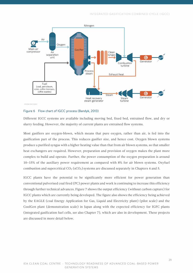
Cycle. A diagram of the process in shown in Figure 6 (Bandyk, 2013). Heat from the gasification and
gas cleaning stages can also be used within the steam cycle or for the air separation unit (compressed
air). Partial integration can be used to raise efficiency and to provide additional plant flexibility.
I N T E G R A T E D G A S I F I C A T I O N C O M B I N E D C Y C L E ( I G C C )
I E A C L E A N C O A L C E N T R E – T E C H N O L O G Y R E A D I N E S S O F A D V A N C E D C O A L - B A S E D P O W E R
G E N E R A T I O N S Y S T E M S
29
Figure 6 Flow chart of IGCC process (Bandyk, 2013)
Different IGCC systems are available including moving bed, fixed bed, entrained flow, and dry or
slurry feeding. However, the majority of current plants are entrained flow systems.
Most gasifiers are oxygen-blown, which means that pure oxygen, rather than air, is fed into the
gasification part of the process. This reduces gasifier size, and hence cost. Oxygen blown systems
produce a purified syngas with a higher heating value than that from air blown systems, so that smaller
heat exchangers are required. However, preparation and provision of oxygen makes the plant more
complex to build and operate. Further, the power consumption of the oxygen preparation is around
10–15% of the auxiliary power requirement as compared with 8% for air blown systems. Oxyfuel
combustion and supercritical CO2 (sCO2) systems are discussed separately in Chapters 4 and 5.
IGCC plants have the potential to be significantly more efficient for power generation than
conventional pulverised coal fired (PC) power plants and work is continuing to increase this efficiency
through further technical advances. Figure 7 shows the output efficiency (without carbon capture) for
IGCC plants which are currently being developed. The figure also shows the efficiency being achieved
by the EAGLE (coal Energy Application for Gas, Liquid and Electricity plant) (pilot scale) and the
CoolGen plant (demonstration scale) in Japan along with the expected efficiency for IGFC plants
(integrated gasification fuel cells, see also Chapter 7), which are also in development. These projects
are discussed in more detail below.

I N T E G R A T E D G A S I F I C A T I O N C O M B I N E D C Y C L E ( I G C C )
I E A C L E A N C O A L C E N T R E – T E C H N O L O G Y R E A D I N E S S O F A D V A N C E D C O A L - B A S E D P O W E R
G E N E R A T I O N S Y S T E M S
30
Figure 7 Roadmap of power generation technology development in Japan (Yasui, 2014)
As shown in Figure 7, IGCC and related technologies are under long-term development in Japan, with
investment in R&D ongoing until 2040 and beyond. Current (second generation) IGCC plants have
net efficiencies of 42–51% (LHV), higher than the 43–46% for state-of-the art PC units. Theoretically
net LHV efficiencies for commercially available IGCC plants without CO2 capture could be 45.9%
(Wolfersdorf and Meyer, 2017) although new plants are being developed with even higher efficiency
targets.
Figure 8 shows how EAGLE gasification systems can work with lower grade coal than many
conventional PC systems, both in terms of ash melting temperature and fixed volatile matter
(Nakamura, 2016).
Figure 8 Coal types which can be used in EAGLE gasification systems (Nakamura, 2016)

I N T E G R A T E D G A S I F I C A T I O N C O M B I N E D C Y C L E ( I G C C )
I E A C L E A N C O A L C E N T R E – T E C H N O L O G Y R E A D I N E S S O F A D V A N C E D C O A L - B A S E D P O W E R
G E N E R A T I O N S Y S T E M S
31
Low-rank coals can have lower ash fusion temperatures which can lead to ash slagging problems and
reduced operation in conventional PC boilers, but this is not an issue in IGCC systems. This would
make IGCC a potential HELE option for countries where coal quality can be low and water scarce.
IGCC plants can be operated to run efficiently even when firing coals with high ash and/or high
sulphur. In addition, the hot syngas is cleaned prior to combustion which removes the need for flue
gas cleaning technologies to be installed downstream of the combustion zone. Hot gas clean-up
systems remove particulates, sulphides and trace elements. However, not all IGCC plants have hot gas
clean up. The syngas is produced at temperatures of up to 1700°C (depending on the type of gasifier)
and this is too high for most gas cleaning systems. The gas is therefore cooled by heat exchangers
which leads to wasted energy and the potential for corrosion and damage of the cooling systems (CTW,
2018, Wolfersdorf and Meyer, 2017).
Much of the current R&D in IGCC technologies focuses on removal of CO2 from the syngas, a process
which should be much simpler than the removal of CO2 from the more complex flue gases from
conventional coal combustion systems. However, CO2 capture and processing requires energy and, as a
result, the overall net efficiency of an IGCC plant could drop by around 7–11%, leading to net plant
efficiencies of around 35–41%, with the overall value being plant and coal dependent. For pulverised
coal plants, the reduction in efficiency of post-combustion CO2 capture is estimated at 8–15 percentage
points based on non-capture net efficiencies. IGCC plants are therefore often regarded as an appropriate
technology for future coal-based power as they offer the potential to produce power whilst achieving
zero- or near-zero emissions (Wolfersdorf and Meyer, 2017).
Even without CCUS, IGCC offers potential in terms of reduced CO2 emissions. According to Miyao
(2016) the average subcritical coal-fired power plant produces 958 gCO2/kWh, ultrasupercritical (USC)
plants produce 806 gCO2/kWh, and IGCC plants could have much lower emissions, approaching
660 gCO2/kWh. This lower CO2 emission rate would be a result of the higher efficiency of IGCC systems.
However, this depends on continued development of IGCC systems and associated turbine technologies.
Since the steam cycle is only part of the power production, IGCC plants may use up to 30% less water
for cooling than conventional PC plants, thus potentially offering an advantage in regions with water
stress. If CCS is included, then IGCC plants could offer a smaller footprint than conventional plants
for the same amount of power. The slag produced from most IGCC processes is marketable for cement
production and the sulphur removed during gas clean-up can be sold as a chemical, to the fertiliser
industry for example (CTW, 2018).
3.2 CURRENT DEPLOYMENT
Since previous IEA CCC reports have reviewed IGCC projects in detail, this report does not repeat this
information but instead provides an overview of the major issues reported, along with operating
experience and insight into the challenges of the technology. Table 4 lists those projects which were

I N T E G R A T E D G A S I F I C A T I O N C O M B I N E D C Y C L E ( I G C C )
I E A C L E A N C O A L C E N T R E – T E C H N O L O G Y R E A D I N E S S O F A D V A N C E D C O A L - B A S E D P O W E R
G E N E R A T I O N S Y S T E M S
32
known to be operational or under construction at the end of 2017. It is difficult to obtain information
on the status of existing and planned IGCC projects as many of the companies involved regard the
information as proprietary and therefore do not publish details.
TABLE 4 COAL IGCC PROJECTS OPERATIONAL OR UNDER CONSTRUCTION IN 2017 (BASED ON WOLFERSDORF AND
MEYER 2017; BARNES 2013)
IGCC Plant Start-up Current status Fuel Technology Net
power
output,
MWe
Efficiency,
%
Carbon
capture
Buggenum
(Netherlands)
1994 Closed (2013) Bituminous coal
with biomass
Shell coal
gasification
253 43.0, LHV none
Puertollano,
Spain
1997 Closed (2016) Subbituminous,
high ash hard
coal, pet coke
ThyssenKrupp 335 42.2, LHV Demo
plant
2010-11
Polk County,
Tampa,
US
1996 Potentially
converting to
natural gas
US bituminous
coal, petcoke,
biomass
GE coal
gasification
252 35.4, HHV none
Vresova,
Czech
Republic
1996
(retrofit
2005)
Operational Czech lignite Lurgi type
fixed-bed coal
and Siemens for
liquid
350 50.5, LHV* none
Wabash River,
USA
1995 Converted to
chemical
production
2016
US bituminous
midwestern
coal and
petcoke
CB&I (E-gas) 250 37.8, HHV none
Nakoso, Japan 2007 Operational Bituminous and
subbituminous
coal
Mitsubishi air-
blown coal
gasification
250 42.9, LHV none
Tianjin, China
(GreenGen)
2012 Operational Shenhua
bituminous coal
Huaneng coal
gasifier
250 Expected
48.4, LHV
Planned in
3rd stage
Edwardsport,
Indiana,
US
2013 Operational Illinois
bituminous coal
GE coal
gasification
618 38.5, HHV none
Taean
IGCC No 1,
South Korea
2016 Operational Subbituminous,
bituminous coal
Shell 300 Expected
42.0, HHV
Planned in
later stage
Kemper
County,
US
2016 Converted to
gas
Mississippi
lignite (now
natural gas)
TRIG (KBR)
gasification
582 Expected
28.1, HHV
65%
capture,
3 Mt/y
CO2 for
EOR
Wakamatsu,
Hiroshima,
Japan
(EAGLE)
2002 Under
reconstruction
Subbituminous
coal
Mitsubishi
oxygen-blown
coal gasification
166 Expected
42.7, LHV
Planned in
2nd stage
* Natural gas is used as part of the fuel and the heat output is included in the overall efficiency value

I N T E G R A T E D G A S I F I C A T I O N C O M B I N E D C Y C L E ( I G C C )
I E A C L E A N C O A L C E N T R E – T E C H N O L O G Y R E A D I N E S S O F A D V A N C E D C O A L - B A S E D P O W E R
G E N E R A T I O N S Y S T E M S
33
The Buggenum and Puertollano plants were run as demonstration units for several years and,
although now closed, they provided data and experience which has been beneficial to more recent
projects. Buggenum, which was run commercially, but not profitably, for a few years, reported issues
with gas turbine vibrations, syngas scrubber erosion and slag lumps and fines discharge, among others.
The plant reliability was an issue, although it appears that much of the plant downtime was due to the
requirements to change operation to suit the various coals which were procured from local pulverised
coal plants in a somewhat random manner (NETL, 2017). However, despite this, the unplanned
shut-down time was relatively low, around 5.6% of the potential full availability in 2002. Despite a
move to reduce costs by including biomass in the feed, Buggenum shut down in 2013 due to low energy
prices and the high cost basis of the plant making operation unprofitable (Barnes, 2013).
Puertollano moved forward with a €13.4 million CCS demonstration slip stream project in 2005 and
successfully demonstrated that CO2 could be captured and recycled back into the gasification system
(Barnes, 2013). However, the CCS demonstration never moved beyond the R&D stage and closed with
the rest of the plant in 2016 (Wolfersdorf and Meyer, 2017).
Despite issues with slag tap blockage, corrosion and fouling, the Polk plant in Tampa, USA
demonstrated that the waste slurry from the process could be used as a raw material in the construction
industry (Barnes, 2013).
One of the largest IGCC plants in the world, the 400 MWe Vresova plant in the Czech Republic,
operates with natural gas as a back-up fuel, providing additional flexibility and reliability. The overall
combined cycle efficiency is 50.5% (not directly comparable with power plant efficiencies) and some
of this is provided for district heating (Barnes, 2013).
The Wabash plant in the USA was selected by the US Department of Energy (DOE) as a clean coal
technology demonstration project and started operation in 1995. Throughout its operation, the plant
ran with various local coals and petroleum coke and suffered from reduced plant availability due to
fouling and corrosion as well as candle filter failure (Barnes, 2013). In 2016, the system was bought by
the Phibro Group who intend to convert it into an ammonia fertiliser production facility, using petcoke
as the starting fuel (Phibro, 2016).
Overton (2014) regards the Nakoso project, also in Japan, as a success since the plant has operated
since the early 2000s, and commercially since 2013. Despite early issues with slag discharge and
leakage from cooling tubes, the plant is still operating and is moving forward with options for CCS.
Even damage from the tsunami that followed the 2011 earthquake, which submerged many of the plant
facilities, did not result in extended closure of the plant (Barnes, 2013). It currently runs at 42% net
efficiency with SO2 and NOx emissions in the low single digit parts per million (ppm). The
manufacturer, Mitsubishi Hitachi Power Sector (MHPS) actively markets their technology, claiming a
48% net efficiency for advanced systems and suggesting that these new plants, with higher inlet

I N T E G R A T E D G A S I F I C A T I O N C O M B I N E D C Y C L E ( I G C C )
I E A C L E A N C O A L C E N T R E – T E C H N O L O G Y R E A D I N E S S O F A D V A N C E D C O A L - B A S E D P O W E R
G E N E R A T I O N S Y S T E M S
34
temperatures, can be competitive with conventional coal plants. Two more IGCC plants are planned
for the Fukushima Prefecture (>500 MW each) based on the same MHPS air-blown technology as the
Nakoso plant (see Section 3.3).
The GreenGen project in Tianjin, China, was built in phases. The 266 MW industrial-scale unit was
running by 2012 and by 2014 had operated for almost 6000 hours. The plant was planned to expand
to complete a 500-900 MW plant, running at 47–52% efficiency with a CCU component. Although the
cost overruns have not been made public, they are reported to be ‘substantial’ (Overton, 2014a).
Although no further data have been published, it appears that this project has been shelved.
Edwardsport, USA, is owned and operated by Duke Energy and is claimed to be one of the cleanest
and most efficient coal-fired plants in the world. It runs on both coal and natural gas, with a capacity
factor of over 80%. The plant is possibly best known for the continued legal contest over how the cost
overruns for the plant are to be recovered (see below) (Lydersen, 2016).
The Taean IGCC plant began commercial operation in South Korea in August 2016, operated by Korea
Western Power (Song-hoon, 2016). The project has been developed in conjunction with Doosan
Heavy Industries and is the first of its kind in the country.
The Kemper IGCC project in Mississippi, USA, is perhaps the most contentious of all the IGCC projects
to date. Although the 582 MW unit was designed to fire minemouth lignite, the project ran seven years
late and ended up costing twice the projected amount. US$800 million of these costs were passed on
to shareholders of Mississippi Power, the owners of the plant (Proctor, 2018). The aim was to produce
power (582 MW peak) as well as sulphuric acid and ammonia for sale, and CO2 for enhanced oil
recovery. During its operation Kemper did achieve 224 total days of lignite gasification and met all
environmental permit requirements, achieving 60% CO2 capture and on-spec production of ammonia
and sulphuric acid. However, there were issues with inconsistent quality raw coal which led to issues
with the dryers and also with gasifier seals, tube leaks and excess sour water production (Lunsford,
2017). Eventually the continued cost increases proved excessive and the plant now fires natural gas.
Conca (2017) suggests that it was the combined challenges and costs of working on both the
gasification and the carbon capture system simultaneously which proved too much. But there is also
the low cost of gas to consider; a factor which has affected many coal-based power projects across the
USA. By 2017, natural gas prices had dropped by 60–70%, compared to what they were at the 2010
approval date of the project (Lunsford, 2017).
The Wakamatsu EAGLE (coal Energy Application for Gas, Liquid and Electricity) project was initiated
in 1995 by NEDO and until 2007 it ran as a pilot plant firing 150 t/d subbituminous coal. In 2012 the
plant moved to the demonstration phase and fired 1180 t/d, producing 166 MW based on an oxygen
blown system. The plan is to upgrade the plant during the 2020s to fire 3500 t/d and produce 500 MW,

I N T E G R A T E D G A S I F I C A T I O N C O M B I N E D C Y C L E ( I G C C )
I E A C L E A N C O A L C E N T R E – T E C H N O L O G Y R E A D I N E S S O F A D V A N C E D C O A L - B A S E D P O W E R
G E N E R A T I O N S Y S T E M S
35
with a net thermal efficiency of 46% (Wolfersdorf and Meyer, 2017). The plant reported early issues
with slag tap blockage, pipe clogging and corrosion (Barnes, 2013).
The current phase of EAGLE development began in March 2017 with the Osaki CoolGen Project, the
next step towards development of an IGFC system (see Section 3.3 below) (NEDO, 2017). CoolGen is
an oxygen-blown IGCC unit firing low cost coal. The intention is to get IGCC working with carbon
capture (90%) whilst maintaining a 40% net (HHV) efficiency, and then move forward to IGFC. The
CCS section of the project is projected to be online by 2019/20. The operators plan to run the plant
for over 5000 hours continuously, providing 70% availability, with emissions of SO2, NOx and
particulates all below 10 ppm (Nakamura, 2016).
According to Wolfersdorf and Meyer (2017), the number of coal-fired IGCC units in operation
globally will have increased from 83 (70% of the total IGCC capacity for all fuels) in 2014 to 151 (81%
of the total IGCC capacity) by 2019. This includes IGCC plants used for chemical production. The
National Energy Technology Laboratory (NETL) of the US DOE, created a database of current and
proposed US gasification. The database currently (accessed July 2018) lists 59 projects in the USA;
however, this includes solid fuel to liquid and other chemical plants along with delayed and cancelled
projects. The database has not been updated since June 2016 and therefore does not reflect the current
status of all projects.
3.3 FUTURE DEVELOPMENT
As mentioned in Section 3.2, many projects have stalled or closed but several plants are currently
running and providing valuable information for the next phase of the technology. IGCC power plants
that have been planned worldwide are summarised in Table 5, although most of them are delayed, on
hold, or unlikely to proceed.

I N T E G R A T E D G A S I F I C A T I O N C O M B I N E D C Y C L E ( I G C C )
I E A C L E A N C O A L C E N T R E – T E C H N O L O G Y R E A D I N E S S O F A D V A N C E D C O A L - B A S E D P O W E R
G E N E R A T I O N S Y S T E M S
36
TABLE 5 COAL IGCC POWER PROJECTS AT THE PLANNING STAGE (EXPANDED FROM WOLFERSDORF AND MEYER,
2017, MC, 2018; ROKER, 2018)
Project and
location
Start-up Fuel Gasification
technology
Net
power
output,
MWe
Carbon
capture
Project and location
Dongguan
Taiyangzhou,
China
2019
(delayed)
Coal TRIG (KBR) 800 1 Mt CO2/y Dongguan
Taiyangzhou, China
Karachi,
Pakistan
2019 Coal SES/U-Gas 100 none Karachi, Pakistan
Kochi Kerala,
India
2019
(delayed)
Pet coke Unspecified 500 none Kochi Kerala, India
Dadri, India 2019
(delayed)
Coal BHEL 100 none Dadri, India
Hirono/Nakoso,
Japan
2020/21 Bituminous
and
subbituminous
coal
Mitsubishi
air blown
2 x
540
none Hirono/Nakoso, Japan
China Huadian
Power, China
Delayed Coal ECUST
(OMB)
200 none China Huadian Power,
China
Lianyungang,
China
Delayed Coal Unspecified 2 x
400
1 Mt CO2/y
for EOR
Lianyungang, China
North
Killingholme,
UK
On hold Coal Unspecified 470 90% capture,
2.5 Mt
CO2/y
North Killingholme,
UK
Don Valley, UK On hold Coal Shell 650 5.0 Mt
CO2/y for
EOR
Don Valley, UK
Caledonia Clean Energy, UK
Reserve project
Coal Siemens 570 90% capture, 3.8 Mt CO2/y
Caledonia Clean Energy, UK
Teesside, UK Reserve project
Coal GE 850 2.5 Mt CO2/y for EOR
Teesside, UK
The Hirono IGCC project in Hirono-machi, Fukushima, Japan, has undergone a few design changes
but the MHPS system entered the construction phase in April 2018 and is expected to begin operation
in September 2021. The sister plant, Nakoso, in Iwaki, Fukushima, is slightly further forward in
construction and should be online by September 2020 (Roker, 2018).
According to Wolfersdorf and Meyer (2017), the majority of the IGCC projects under development
are subject to delay. Of the twenty IGCC projects proposed in 2013 for China, only three appear to be
moving further towards development. The plant in Dadri, India, is subject to delay due to disputes
over intellectual property whilst the UK proposals are unlikely to proceed much further since,
although the UK government has announced a move away from ‘unabated’ coal by 2025 (Cockburn,
2017), funding for CCS has been curtailed.

I N T E G R A T E D G A S I F I C A T I O N C O M B I N E D C Y C L E ( I G C C )
I E A C L E A N C O A L C E N T R E – T E C H N O L O G Y R E A D I N E S S O F A D V A N C E D C O A L - B A S E D P O W E R
G E N E R A T I O N S Y S T E M S
37
A report by the US-China Energy Center (USCEC, 2014) notes that there are eight international and
seven Chinese licensors successfully commercialising their technology in China with over 180 projects
proposed or planned throughout 28 of the 30 Chinese provinces. It is expected that Chinese
technologies will be used in around 57% of the projects.
There are other IGCC-based technologies under development, including integrated gasification fuel
cells (IGFC). Wolfersdorf and Meyer (2017) note that IGFC technology still requires ‘significant
efforts for research and development’, listing eight IGFC-CCS and four oxyfuel-IGCC projects which,
although dating as far back as 1992, are still regarded as ‘concept studies’ (see also Chapter 5). The
Osaki CoolGen Project in Japan is currently running as an oxygen-blown IGCC with plans to switch to
an IGFC system with CO2 capture in the future. The NEDO plan for oxyfuel IGCC and entrained flow
steam gasification has a target year for technology establishment of 2030-2035. NEDO are proposing
an oxyfuel IGCC plant with CO2 capture with a net thermal efficiency of 42% (expecting only a
4 percentage point efficiency loss for the CO2 capture and for the cost of the CO2 capture to decrease
from 0.03 US$/kWh to 0.01 US$/kWh) (Yasui, 2014). According to Miyao (2016), IGFC plants should
achieve efficiencies of around 55% and could be available by 2025. Gas turbine fuel cell combined
cycle plants (GTFC) could reach 63% efficiency, with CO2 emissions as low as 280 g/kW. NEDO hopes
to have IGFC operational as early as 2025. In 2030 or later, NEDO predicts the development of closed
IGCC, a system which could circulate CO2 in the exhaust gas as an oxidant throughout a gasification
furnace or gas turbine with no CO2 release to the environment at all (these systems are discussed later
in this report: oxyfuel combustion systems are discussed in Chapter 5; sCO2 systems in Chapter 6; and
fuel cells in Chapter 7).
3.4 CHALLENGES
As mentioned above, IGCC systems offer several advantages over conventional coal combustion systems
including potentially higher plant efficiencies, lower emissions, the capacity to fire various grades of
coals, lower water requirements, and a smaller plant footprint. But IGCC technologies have not yet been
deployed as quickly as some predicted. Wolfersdorf and Meyer (2017) list several reasons why:
• economic viability, caused by high capital cost, which is not compensated for by lower operating
costs;
• low availability, due to the complex processes involved; and
• high perceived risk, making it harder to obtain funding.
There are also issues related to the additional CCS capability of IGCC systems, such as uncertainty
over the legal framework regarding CCS and that fact that CCS adds to the overall cost for all projects
(see below). Further, risk assessments for CO2 capture on IGCC units have revealed ‘major
uncertainties’, especially for large-scale projects which could have significant effects on their financing
(Wolfersdorf and Meyer, 2017).

I N T E G R A T E D G A S I F I C A T I O N C O M B I N E D C Y C L E ( I G C C )
I E A C L E A N C O A L C E N T R E – T E C H N O L O G Y R E A D I N E S S O F A D V A N C E D C O A L - B A S E D P O W E R
G E N E R A T I O N S Y S T E M S
38
3.4.1 Technology requirements
Currently, most of the IGCC plants in operation and under development are produced by the major
suppliers – GE, Shell, Lurgi, OMB (ECUST), SEDIN and Siemens. Together these suppliers provided
78% of the syngas capacity in operation in 2014, although this may decrease to 67% by 2019 as new
systems become available (Overton, 2014a).
Overton (2014a) lists ways in which IGCC plants could be made more economical and productive:
• advanced air separation methods to improve the efficiency of oxygen firing;
• improved designs and materials to increase gasifier component life and to allow larger ones with
higher temperatures;
• use of flue gas and other low-grade heat sources to reduce costs and energy consumption for coal
drying;
• ‘dry solid’ pumps or use of supercritical CO2 instead of water for preparing the coal slurry;
• advanced higher-temperature particulate removal devices and hot gas desulphurisation; and
• advanced gas turbines, improved aerodynamics, and materials advances to allow higher firing
temperatures and larger blade sizes that improve efficiency and output.
Overton (2014a) is hopeful of significant progress due to ongoing improvements in natural gas-fired
turbine performance and the ‘robust’ R&D underway in gasifier technology.
A previous report from the IEA CCC (Zhu, 2015a) summarised the experience of hot gas cooling
systems in the IGCC plants listed in Table 5. Zhu’s report concluded that the syngas cooling systems
currently in operation are sound, but that ongoing R&D will lead to more efficient and reliable systems.
Improved cooling systems could lead to lower energy consumption within the plant (and therefore
greater overall plant efficiency) as well as increased availability of gas cleaning options, ultimately
reducing plant operating costs.
The status of CCUS is covered in several complementary reports from the IEA CCC (Zhu, 2018:
Lockwood, 2016, 2017a) and is therefore not repeated in this report. However, the challenge of
moving CCUS into commercial and economic practice is clear. Because some IGCC plants (oxygen-
blown systems) can produce clean combustion gases already at high pressure, the cost of CCS could
be lower for IGCC units than for conventional combustion systems. Therefore, some investors may
see IGCC as a step towards coal-fired power generation with CCUS. New technologies such as oxygen
transport membranes could have a capital cost 25–36% lower than that for cryogenic air separation
systems (Wolfersdorf and Meyer, 2017). Costs are expected to decrease as the technology develops
but, for the moment, CCUS costs simply add to the risk and expense of new IGCC projects.

I N T E G R A T E D G A S I F I C A T I O N C O M B I N E D C Y C L E ( I G C C )
I E A C L E A N C O A L C E N T R E – T E C H N O L O G Y R E A D I N E S S O F A D V A N C E D C O A L - B A S E D P O W E R
G E N E R A T I O N S Y S T E M S
39
3.4.2 Economics
Almost all the IGCC literature reviewed for this report agrees that the major challenge for IGCC
adoption is the cost. A significant part of this issue is the uncertainty of capital cost estimates because
there are no standardised IGCC systems on which to base future plant cost estimates (Wolfersdorf and
Myer, 2017). Examples of capital costs for IGCC units are around 1790 US$/kW (baseline year 2001)
for the Polk plant in Tampa, only slightly lower than for the earlier Puertollano plant (1850 US $/kW;
base year 1991). The US Energy Information Administration (EIA) gives example ‘overnight capital
costs’ of fossil fuel plants which range from 978 $/kW for natural gas combined cycle plants to
3636 US$/kW for ultrasupercritical coal combustion (without CCS, 2016US$ base) (EIA, 2016).
Unfortunately, the EIA study does not include an example overnight capital cost for IGCC and so a
direct comparison is not possible.
As mentioned above, the Edwardsport plant in the USA had total costs reaching US$3.5 billion, 75%
above initial estimates. One of the most famous and costly cases is that of the Kemper County plant
which overran its planned start-up date by almost two years and was significantly over budget, despite
funding of US$245 million from the US DOE. Predicted costs of US$2.88 billion escalated to
US$5.43 billion (Wolfersdorf and Myer, 2017) with a final overall cost of US$7.5 billion being cited in
the settlement process (Proctor, 2018). The plant now runs as a standard natural gas combined cycle
system and is expected to continue doing so. According to Wagman (2017), the low cost of gas in the
USA and the flexibility it allows for ramping up and down to meet demand meant that the switch to
gas was the clear obvious economic choice, rather than to try to address delays with the coal
gasification system. There was heated debate between the Mississippi Power company and the public
utility regulator on how the deficit for the plant should be covered, with the regulators arguing that
electricity consumers should not be expected to cover this loss (Power Engineering, 2017). However,
it seems now that the company stakeholders will bear the cost themselves (Proctor, 2018).
Overton (2014a) cites a spokesman for Electric Power Research Institute (EPRI): “The combination of
the substantial cost overruns at the two US IGCC projects built this decade and relatively low natural gas
prices present in North America has dried up interest in IGCC amongst US power producers.’
And so, as stressed by Wolfersdorf and Meyer (2017), IGCC plants are expensive and, without CCS,
do not offer enough flexibility or improved operational economics to give them any advantage over
conventional gas plants or supercritical coal plants. Several years ago, James (2011) noted that,
although several IGCC-CCS projects were being considered in Europe, the costs were high, and the
projects would ‘only make sense’ if carbon were restricted. However, if there was a carbon-based
financial incentive, then IGCC would be competitive. James also noted that the technology was moving
forward ‘slowly’ to drive costs down but that projects were slowing further or stalling due to the
uncertainty over the future for coal and CCS as well as general financial constraints.

I N T E G R A T E D G A S I F I C A T I O N C O M B I N E D C Y C L E ( I G C C )
I E A C L E A N C O A L C E N T R E – T E C H N O L O G Y R E A D I N E S S O F A D V A N C E D C O A L - B A S E D P O W E R
G E N E R A T I O N S Y S T E M S
40
IGCC, it seems, may be regarded as currently too expensive for most economies. However, the lessons
learned from the current and planned plants, especially the growing interest in Asia, should lead to
reduced costs for future generations of the technology. Interestingly, Ali (2016) suggests that IGCC
may work in Pakistan simply due to the low costs of coal production and low labour rates in the
country.
3.4.3 Barriers to be addressed
Barnes (2013) described a risk framework that applies to most clean coal technology projects – risk
escalates between the design and development phase into the engineering and construction phase as
decisions and commitments are made which may affect future flexibility and success. Wolfersdorf and
Meyer (2017) suggest that the complexity of IGCC systems makes them more similar, in terms of
engineering, to chemical plants than conventional power plants and, for that reason, some utilities may
be hesitant to invest in such a significant change in skill sets. Overton (2014a) goes further to imply
that the technical complexity of IGCC, and not just the cost, is a major reason why IGCC has not been
adopted as widely as first predicted. Overton (2014a) cites delays, technical challenges and mechanical
failures at the Duke plant in the USA as one of the major reasons new plants are stalled or postponed.
Similarly, miscalculations in the type and amount of piping needed at the Kemper plant played a role
in the plant running late and over budget.
IGCC systems are clearly far more complex and more technically awkward to build and operate than
standard coal-fired systems. There are still some lessons to be learned before IGCC can be regarded as
a standardised utility option. However, IGCC could still be an important future coal technology,
providing high net efficiency, low emissions, and a lower efficiency penalty for CCUS. To increase
IGCC deployment, the following barriers must be overcome (Wolfersdorf and Meyer, 2017):
• reduce the capital costs of building new plant;
• increase operating experience and plant availability;
• increase efficiency and CCUS experience;
• incorporate and demonstrate CCUS; and
• adopt lessons learned from operating plant.
Figure 9 shows the developments being made in IGCC. Each of the circles in the diagram represents a
challenge to be addressed to make IGCC more reliable and affordable. The diagram also indicates
which companies are currently working to address these issues – some are concentrating on reducing
capital costs by increasing the efficiency of the water quench (cooling) systems whilst others are
focused on ensuring that their systems can work with low-grade fuels.
Wolfersdorf and Meyer (2017) conclude that IGCC with CCS is likely to be more commercially viable
than IGCC alone due to the advantages that such plants offer over conventional systems. However,

I N T E G R A T E D G A S I F I C A T I O N C O M B I N E D C Y C L E ( I G C C )
I E A C L E A N C O A L C E N T R E – T E C H N O L O G Y R E A D I N E S S O F A D V A N C E D C O A L - B A S E D P O W E R
G E N E R A T I O N S Y S T E M S
41
overcoming the capital cost issue may require a step-change in carbon pricing to help move the
technology forward.
Figure 9 Developments in coal gasification (Wolfersdorf and Meyer, 2017)
In addition to these technology challenges, Barnes (2013) notes that there are also regulatory and
market risks. Policy issues can be of concern to potential investors as they must consider, for example,
the possibility of environmental standards tightening in the future which would require retrofitting
the plant, or which may reduce the likelihood of the technology competing adequately in a future
energy mix. This would be less of an issue for IGCC plants, which are cleaner than conventional
coal-fired systems. In addition, it can be difficult to obtain finance and insurance for large complex
power plants, especially those using less conventional technology.
3.5 COMMENTS
IGCC is a relatively mature technology which has the potential to produce power from a wide range
of coals more efficiently and cleanly than from conventional pulverised coal fired systems. IGCC
plants also use less water than conventional coal plants and would therefore be more suitable in areas
with limited water supplies. Further, CO2 capture from oxy-blown IGCC plants would be easier and
more cost effective than from conventional PC plants (when CCUS technology is commercially
available – total generating costs may be higher but incremental CO2 capture costs would be lower).
Unfortunately, until the CCUS challenge is met, the other advantages of IGCC are often considered
insufficient to offset the increased cost and perceived risk of this technically complex clean coal
technology. Conversely, whenever CCUS becomes commercially applicable, IGCC-CCUS may prove

I N T E G R A T E D G A S I F I C A T I O N C O M B I N E D C Y C L E ( I G C C )
I E A C L E A N C O A L C E N T R E – T E C H N O L O G Y R E A D I N E S S O F A D V A N C E D C O A L - B A S E D P O W E R
G E N E R A T I O N S Y S T E M S
42
to be far cleaner, more flexible (in terms of input fuel and with the option of polygeneration), and
more cost-effective than conventional coal plants with CCUS.
A review of the IGCC projects so far suggests that the technology is more complex and challenging
than predicted. Most of the plants’ construction ran over budget and time with even the most
successful units costing 15–20% more than a conventional PC plant. Government support in Europe
and the USA has largely ceased and private investors appear to be concerned about the high perceived
risk. If CO2 had more of a global monetary value, then perhaps more money would be invested in IGCC
because of its inherent suitability for CCUS projects. However, many countries currently see IGCC as
too expensive and risky to be considered as anything other than experimental and so, for the moment,
there seems to be a geographical divide in willingness to invest further in IGCC projects. After initial
enthusiasm in the EU and the USA, unexpected technical issues led to delays, and hence overspending,
somewhat tainting the image of the technology. Figure 2 in Chapter 1 showed the ‘Valleys of Death’
for many new technologies and it would seem that the EU and USA projects did not make it through
the second valley. This was largely due to the withdrawal of government funding, although low gas
prices also played a role in the demise of US projects.
Conversely, in China and Japan IGCC is seen as an important technology in the move towards cleaner
and more efficient plants which can fire more challenging coals. Several plants are already being built
with more planned, many with projected modifications through further advanced iterations (such as
fuel cells) and, ultimately, to CCUS addition within the next decade or so. Thus, it is likely that Asian
IGCC investment could lift the technology out of the ‘Valley of Death’ zone and make it available
commercially.
Ultimately, IGCC seems to be accepted as a strong part of the future energy mix in those countries
which regard coal as remaining important and who have industrial and financial partners who are
willing to continue to invest in the critical final stages of the movement of this technology from being
regarded as experimental to being accepted as truly commercial. China is showing commitment to
IGCC with over 180 projects proposed, based on Chinese technology. However, not all proposed
projects make it past the proposal stage, so it is unclear how many of these projects will make it to the
construction phase, especially since coal use in China is slowing. Once the technology is proven and
affordable, IGCC could be deployed effectively in areas with low quality coals and water restrictions.

P O L Y G E N E R A T I O N
I E A C L E A N C O A L C E N T R E – T E C H N O L O G Y R E A D I N E S S O F A D V A N C E D C O A L - B A S E D P O W E R
G E N E R A T I O N S Y S T E M S
43
4 P O L Y G E N E R A T I O N
Polygeneration is the manufacture of more than one product from one fuel source. This chapter does
not consider polygeneration relating to combined heat and power (CHP) production, to maintain the
focus on advanced combustion power production. Similarly, this chapter excludes coal liquefaction,
or coal-to-x as these are commonly single processes, producing only one product or a range of chemical
products and are therefore outside the scope of this report. This chapter concentrates on systems
where coal is converted to both power and chemicals or fuels either simultaneously or sequentially
through the same facility. Coal-based polygeneration systems are gasification based as it is the
gasification process that separates the coal into different chemical products.
The IEA CCC produced a review of polygeneration from coal in 2008 (Carpenter, 2008) but there has
not been enough new material published since then to warrant a new, full report on the topic. This
chapter builds on the information given in the 2008 report, updating the progress in the development
of this technology.
4.1 PRINCIPLES OF THE TECHNOLOGY
Polygeneration systems involve the gasification of coal which can then be processed to produce gas
for power generation and other chemical products. Polygeneration IGCC systems have an advantage
of increased flexibility over standard IGCC plants as they offer the ability to switch from power
production to chemical production when energy prices are low and vice versa. These systems can
utilise a wide range of fuels, including waste.
Polygeneration gasification produces a syngas that can be used for numerous products, including:
• electricity, via combined cycle generation (see Chapter 3);
• substitute natural gas (SNG);
• hydrogen;
• transport fuels (diesel, gasoline, methanol and dimethyl ether);
• chemicals; and
• fertilisers.
By-products such as sulphur or sulphuric acid can also be sold to increase revenue. Polygeneration is
therefore capable of producing power and various potential products from coal, the combination of
which can be selected to suit local requirements and markets. As with IGCC, polygeneration systems
have low emissions of pollutants and the potential for CCUS.
The fuel used can vary significantly, from various grades of coal through to biomass and waste
materials. However, like IGCC, polygeneration systems are more complex and thus potentially riskier
in terms of operation and investment than conventional coal combustion systems.

P O L Y G E N E R A T I O N
I E A C L E A N C O A L C E N T R E – T E C H N O L O G Y R E A D I N E S S O F A D V A N C E D C O A L - B A S E D P O W E R
G E N E R A T I O N S Y S T E M S
44
The basic flow chart for a polygeneration system is shown in Figure 10.
Figure 10 Polygeneration from electric power to hydrogen to chemicals (the Texas Clean Energy Project)
(Overton, 2014b)
As with IGCC systems, there are several types of gasification system which can be used for
polygeneration: entrained flow, fluidised bed, and moving bed systems; the choice is determined by
the coal composition and rank and the products required. Although the IEA CCC report on
polygeneration from 2008 is 10 years old, the chapters on the chemistry of polygeneration are detailed
and relevant and the interested reader is referred to it (Carpenter, 2008).
As discussed in Chapter 3 gasification is more efficient as a means of power production than
conventional coal combustion. Polygeneration plants firing coal could theoretically achieve 55–60%
efficiency in terms of both power and chemical production. The fuels produced by gasification systems
can be significantly cleaner than those from petroleum (Overton, 2014b).
4.2 CURRENT DEPLOYMENT
Wolfersdorf and Meyer (2017) suggest that, due to the flexibility and potential for multiple
commercial output streams (power and chemical products), polygeneration IGCC is a more promising
technology than IGCC for power alone and therefore has better chances of implementation in the short
term. However, this does not yet seem to be happening in practice. Of the projects listed by Carpenter
(2008), few, if any, are still under consideration and none have reached deployment at any notable
scale. In the USA there were several polygeneration plants proposed in the early 2000s, including
Agrium (the Kenai Blue Sky Project), Clean Coal Power Resources, Rentech Energy Midwest, Erora,
Synfuels Inc, Bull Mountain Development, Summit Power and the American Electric Power
Mountaineer Plant. Each of these plants either converted to solely power or solely chemical

P O L Y G E N E R A T I O N
I E A C L E A N C O A L C E N T R E – T E C H N O L O G Y R E A D I N E S S O F A D V A N C E D C O A L - B A S E D P O W E R
G E N E R A T I O N S Y S T E M S
45
production, or stalled completely (Carpenter, 2008). In the current NETL gasification database (last
updated 2016, both the US and global databases included) there are seven plants listed with
polygeneration potential, all in the USA (East Dubuque, HECA, Hyperion, Indian Rockport, Lake
Charles, Lima Energy and TCEP). All these projects have since stalled or been abandoned completely.
Confirming the status of such projects is challenging – companies rarely publish information on
unsuccessful projects. For example, in 2007, Altona Resources proposed a polygeneration plant to
produce power and liquid fuels at Ackaringa in South Australia. The latest update on the Altona
Resources website (www.altonareources.com) shows a feasibility study from 2013 focusing solely on
coal to methanol for the site, suggesting that the polygeneration approach did not pass subsequent
rounds of feasibility studies.
There are reports of a few IGCC plants in Asia running as polygeneration systems, producing chemicals
and/or hydrogen as well as power. This includes the Yankuang Group in China which has sites which
produce 1 Mt of oil, 9 Mt of methanol, acetic acid, ammonia and urea. The CO2 from the sites is reused.
Although the power generation from the site is not described, the company does refer to ‘waste heat
power generation’. The Yankuang Group has another 104 projects in China and further afield but
refers to these as gasification projects and does not specify polygeneration (Yankuang, 2018). The
Shanxi Lu’an plant, also in China, was originally planned as a polygeneration site to produce liquid
fuels and 11.5 MWe (Carpenter, 2008). However, the site, which began operation in 2010, now runs
purely as a coal to syngas plant and does not appear to be producing power (GSG, 2018).
GreenGen, the China Huaneng Group’s project in Tianjin, China, was first proposed as a
polygeneration plant in 2005. However, since then the plant has been listed as an IGCC unit with no
polygeneration capacity, with an estimated completion date of 2020 or beyond (GCCSI, 2018).
Similarly, early research into options for coal gasification in Japan (such as the EAGLE project,
see Chapter 2) focused entirely on either power generation or coal-to-x with no polygeneration plants
in operation or even under development.
Europe also had several early proposals for coal-to-x and/or polygeneration units such as Hypogen
(EU), Dynamis (EU) and Zecomix and COHYGEN (Italy). However, again, none of these projects have
emerged as an active polygeneration plant.
4.3 FUTURE DEVELOPMENT
Although all the polygeneration projects launched during the early 2000s have stalled, been abandoned
or focused on either power or coal-to-x, several countries still see potential for the technology.
4.3.1 Europe
Germany has a target to produce 80% of its electricity from renewable sources by 2050 and so is
considering several new advanced technologies, including polygeneration, to ensure baseload power.

P O L Y G E N E R A T I O N
I E A C L E A N C O A L C E N T R E – T E C H N O L O G Y R E A D I N E S S O F A D V A N C E D C O A L - B A S E D P O W E R
G E N E R A T I O N S Y S T E M S
46
Coal or lignite polygeneration systems could be ideal as, when electricity prices are high, the plant can
run as a power utility and, when they are low, the operation can shift to chemical production. Buttler
and others (2018) looked at the predicted cost of polygeneration in Germany, taking the merit order
of power generation to the grid into account – that is, the study addressed the variable electricity costs
which arise due to fluctuating demand from the electricity grid. The model considered two plants:
• IGCC plant – power generation only; and
• IGCC – methanol – polygeneration unit producing both power and chemicals.
The study assumed that both plants used the same gasification and power generation system but with
different heat integration. Lignite was used as the main fuel and was dried as part of the plant process.
Gasification in the plant was shifted to the H2-CO ratio required for the desired product (SNG or
methanol).
TABLE 6 COMPARISON OF IGCC-POLYGENERATION (BUTTLER AND OTHERS, 2018)
IGCC – SNG IGCC – Methanol
Mode:
maximum electricity
Mode:
maximum materials
Mode:
maximum electricity
Mode:
maximum materials
Pfuel 1000 MW (LHV) 1004 MW (LHV)
Pelectricity 262 MW 17 MW 265 MW 0 MW
Pmaterial 249 MW 622 MW 256 MW 639 MW
Table 6 shows the power output from the fuel (Pfuel) depending on whether the plan is running to
maximise electricity (Pelectricity) or to maximise SNG or methanol production (Pmaterial). The electricity
outputs from both plants are effectively the same (249–265 MWe). The unit producing methanol is
suggested to be more flexible than that producing SNG as it can reduce its net electricity output to zero.
Buttler and others (2018) provide a useful comparison of investment costs and power production costs,
as shown in Table 7.

P O L Y G E N E R A T I O N
I E A C L E A N C O A L C E N T R E – T E C H N O L O G Y R E A D I N E S S O F A D V A N C E D C O A L - B A S E D P O W E R
G E N E R A T I O N S Y S T E M S
47
TABLE 7 ECONOMIC COMPARISON OF 1000 MW IGCC AND POLYGENERATION SYSTEMS (BUTTLER AND OTHERS,
2018)
Plant type Investment cost
(total overnight
costs), € billion
Levelised cost
of electricity,
€/MWh
COMMENT
IGCC 1.52 112–117 Levelised costs are well above average electricity
prices. Even if fuel and CO2 prices are favourable, the
plant would still be less profitable than others
Coal-to-SNG 1.27 56–58 These prices are not competitive with current SNG
import prices (17–31 €/MWh)
Coal- to-methanol 1.37 61–63 ‘Methanol costs are higher’ (assuming ‘cost’ = ‘price’, no
value given) and so this seems the best option
IGCC-SNG 1.43 N/A ‘Not economically viable’
IGCC–methanol 1.56 N/A This concept was shown to have a positive net present
value but has no advantage over a pure methanol
synthesis plant
The economic analysis summarised in Table 7 shows that the IGCC polygeneration plant options have
significantly higher investment costs (€1.52 billion) than simpler equivalent coal-to-x plants
(€1.27 billion for SNG, €1.37 billion for methanol). But it would be hard even for the conversion of
coal to SNG to compete with other SNG sources in the region. Coal to methanol alone could be viable
but this would depend on the long-term purchase price of coal and the sale price of methanol.
In Germany, the Technical University of Darmstadt is developing the FABIENE project, an IGCC
system with the option to produce fuels, methane, methanol and ammonia through the
Fischer-Tropsch process. The plant, funded by the Ministry of Economics as part of the COORETEC
initiative, has already run four two-week test campaigns at pilot scale. The project is currently
concentrating on modelling the potential for a full-scale minemouth plant, shown in Figure 11.
Figure 11 FABIENE project plan, Germany (Heinze and others, 2018)

P O L Y G E N E R A T I O N
I E A C L E A N C O A L C E N T R E – T E C H N O L O G Y R E A D I N E S S O F A D V A N C E D C O A L - B A S E D P O W E R
G E N E R A T I O N S Y S T E M S
48
The proposed plant (100-300 MWth; produced by ThyssenKrupp and RWE) is based on a stationary
fluidised bed gasification plant in two units, to first dry and then gasify the lignite. There are various
gas cleaning steps before the syngas is combusted in a gas turbine. The model considered power
production with and without CCUS, and methanol synthesis with CO-shift or with electrolyser
conversion. With respect to emissions, the power-only system with CCUS had lower emissions than
the other options simply because of the CCUS facility, as shown in Figure 12. The polygeneration
option had around twice the CO2 emissions of the power-alone version. Emissions were also higher
from the system converting syngas to methanol through the CO-shift method, although a significant
portion of the carbon from the coal ends up in the methanol rather than as CO2.
Figure 12 Emissions from the FABIENE project options (Heinze and others, 2018)
Heinze and others (2018) then considered the cost of the project, considering the potential effect of
the CO2 allowance in Europe, and the results are shown in Figure 13.

P O L Y G E N E R A T I O N
I E A C L E A N C O A L C E N T R E – T E C H N O L O G Y R E A D I N E S S O F A D V A N C E D C O A L - B A S E D P O W E R
G E N E R A T I O N S Y S T E M S
49
Figure 13 Economics of the FABIENE project (Heinze and others, 2018)
The figure shows that the production of methanol is favoured over the production of power at current
CO2, electricity and methanol prices. This agrees with the results from Buttler and others (2018),
discussed above. Conversely, power production will become more economically viable in periods of
high energy demand. The plan is for the study to continue and the model will consider different
products such as SNG and alternative fuels.
In Greece, Atsonios and others (2017) have carried out a model analysis of a co-pyrolysis of biomass
and conventional fossil fuels with the production of diesel and gasoline. Biomass has a high content of
hydrogen compared to coal whereas coal has a higher energy density; blending the fuels can boost the
overall efficiency of polygeneration. The model compared blend ratios of coal to biomass with the aim
of designing for maximum yield. The energy balance calculations showed that around 30% of the heat
input from a 60% coal blend was used for the heat of pyrolysis and gasification of the char. If the heat
source could be replaced by solar energy, then the fuel productivity would increase as coal could be
used solely as a source of materials rather than heat. Figure 14 shows the process diagram of a 60%
coal to biomass fuel mix.

P O L Y G E N E R A T I O N
I E A C L E A N C O A L C E N T R E – T E C H N O L O G Y R E A D I N E S S O F A D V A N C E D C O A L - B A S E D P O W E R
G E N E R A T I O N S Y S T E M S
50
Figure 14 Sankey diagram of a co-pyrolysis case study (60% coal to biomass) (Atsonios and others, 2017)
Although the electricity production of the system is over 3800 kWe, the actual output is significantly
lower at only 282 kWe because of the power consumption of the process units – pumps, gas blowers
and compression systems. The most energy demanding component is the syngas compressor, which
uses over one-third of the produced power in this model (1344 kWe). Atsonios and others (2017)
stress that this is a model based on numerous assumptions and that further study would lead to more
accurate results.
In Poland, there is a polygeneration project proposed and led by the power utility, Tauron. The
proposal, which is now at the feasibility stage, aims to use waste coal in a gasification plant which may
have polygeneration potential. Although no decision on the project has been made over the past
12 months, Sobolewski (2018) is optimistic that Poland could have the first EU coal
gasification/polygeneration plant within the next few years.
4.3.2 USA
There have been a significant number of proposals for polygeneration plants in the USA, many of which
are still listed on the NETL database. However, none have reached full-scale. The plants with the highest
profile were probably the Texas Clean Energy Project (TCEP, 200 MWe) and the Hydrogen Energy
California Project (HECA, 300 MWe). Both plants planned to produce urea and power as well as capturing
90% of the CO2 produced. Even as recently as 2017, it was still suggested that these projects could be online
by 2020 (Wolfersdorf and Myer, 2017). However, it appears that these plants have also stalled.
TCEP was a 400 MW coal IGCC plant planned for Odessa, Texas, USA. In addition to power, the plant
was initially proposed to produce 700 kt/y of urea for the US fertiliser market. The plant designers
also planned to capture 90% of the CO2 produced at the facility. The US$2.4 billion project was to be

P O L Y G E N E R A T I O N
I E A C L E A N C O A L C E N T R E – T E C H N O L O G Y R E A D I N E S S O F A D V A N C E D C O A L - B A S E D P O W E R
G E N E R A T I O N S Y S T E M S
51
run by Summit Power. According to the original designs, during baseload operation the plant would
produce 377 MW of power, 106 MW of which would be used to run the major project equipment –
including 42 MW for urea production and 16 MW to compress CO2. An MOU was signed with China
Huanqui Contracting and Engineering in 2014, and, together with Siemens, they acted as the lead
engineering company on the project (PT, 2014). However, the current project description on the
www.summitpower.com site describes the project as an IGCC plant with carbon capture for enhanced
oil recovery – the plan to include polygeneration appears to have been shelved.
• By May 2016, US$116 million had been spent of the US$450 million budget from the US DOE for
the TCEP. However, due to some deadlines being missed, several private-sector backers
withdrew, and the US DOE also decided to withdraw the remaining funds. The company behind
the project has subsequently gone into liquidation (Collier, 2018).
The HECA project received US$408 million from the US DOE (Overton, 2014b). However, the website
www.hydrogenenergycalifornia.com has not been updated since September 2013, implying that this
project has also stalled.
Overton (2014b) suggested, even before the TCEP and HECA projects stalled, that polygeneration
systems needed better policy support in the USA. Tax credits for CO2 are not structured such that a
facility can predict for how long it will receive credits, making budgeting difficult. Finding investors
has also proven difficult as the technology is so new and complex.
Back in 2007, the Pew Centre for Global Climate Change published a review of the potential for
gasification and polygeneration in the future for Ohio. The study identified industries in the state which
could be customers for a site delivering products such as sulphur and ammonia and created a list of
recommendations to be addressed before investment in any polygeneration facility (Pew Centre, 2007):
• Develop public mechanisms for financing. This would include multiple partners to ensure
reliable markets for the products – power, natural gas or chemicals.
• Create an industry database and information system of participants which would include details
of products and capabilities.
• Expand networking to discuss issues and challenges which would include state officials,
administrators, industry executives and programme directors.
• Undertake in-depth studies of potential markets for the main potential products:
• specialty and bulk coal-based chemicals;
• electricity;
• natural gas;
• CO2 for enhanced oil recovery;
• emission reduction credits; and
• coal prices and availability.

P O L Y G E N E R A T I O N
I E A C L E A N C O A L C E N T R E – T E C H N O L O G Y R E A D I N E S S O F A D V A N C E D C O A L - B A S E D P O W E R
G E N E R A T I O N S Y S T E M S
52
The Pew study concluded that a polygeneration plant in Ohio could increase the state’s output by
US$1.1 billion with companies in the region accounting for 95% of the benefits attained through the
construction phase. A polygeneration plant was later planned for Ohio – the Lima Project (NETL,
2018a). However, there have been significant delays and changes of management and, according to
King (2015), if the plant does go ahead, it is likely to be a coal to gas plant with no polygeneration
capability.
4.3.3 China
The ‘863 Plan’ in China was created during the 10th Five-Year Plan (2001-2005) during which
320 million Yen (around US$47 million) were invested in clean-coal technologies (Sun, 2011). In 2013,
the Chinese ‘Office of Advanced Energy Technology for the 863 Program’ held a meeting of experts at
which it was announced the coal gasification-based polygeneration had passed technology acceptance,
implying that polygeneration had been sufficiently proven to move towards full-scale deployment.
This was based on results reported from several studies including slurry and pressurised gasifiers, and
synthetic oil production. Of specific interest was the reference to a 160 kt/y high temperature
Fischer-Tropsch synthesis oil demonstration plant capable of cogeneration with a 10 MW gas turbine.
However, at the same meeting, one of the company directors is quoted as saying, somewhat
ambiguously, that “IGCC cogeneration is a dream” (Lifeng, 2013).
Although it is accepted that China is doing the most work on polygeneration, there is surprisingly little
published relating to actual projects – most of the literature is technical and experimental and was
published before 2010. And there are only a few Chinese companies that will share information on the
development work online. For example, the China Coal Group has several projects which it regards as
polygeneration. On their website they list their polygeneration and coal chemical work (China Coal,
2018):
• Shaanxi Yulin, 600,000 t/y coal-based olefin (operational);
• Ordos Tuke, 2 Mt/y synthetic ammonia and 3.5 Mt/y urea (operational, first phase);
• Yuanxing, 600 Mt/y coal-based methanol (operational);
• Ordos Mengda, 500 Mt/y engineering plastics project (test phase);
• Shanxi Pingshuo low-grade coal ‘comprehensive utilisation project’ (test phase);
• Jingbian energy, 600 Mt/y coal-based olefin) partly owned by China Coal Group (operational); and
• Zhongtian Synergetic Energy, 1.37 Mt/y coal-based olefin (under development).
The China Coal Group focus is on coal-based olefin and urea production in large-scale coal chemical
bases located in Inner Mongolia-Shaanxi. Energy and water conservation and waste control at these
sites is a priority (China Coal, 2018). However, although polygeneration is listed as part of the
company’s portfolio, there is no information given of any power production at the projects listed above
which implies that the chemical production side of the projects is more economically viable.

P O L Y G E N E R A T I O N
I E A C L E A N C O A L C E N T R E – T E C H N O L O G Y R E A D I N E S S O F A D V A N C E D C O A L - B A S E D P O W E R
G E N E R A T I O N S Y S T E M S
53
Zhang and others (2014) proposed a polygeneration system based on chemical looping combustion,
as described in Chapter 8 The proposed ‘multifunctional energy system’ would use both coal and
natural gas, in a ratio of 3:1. The plant would integrate chemical looping hydrogen production with a
coal-based methanol production system. This study appears to be still at the concept phase.
The State Key Laboratory on Clean Energy Utilisation at Zheijiang University have been developing a
pyrolysis and polygeneration system based on a fluidised bed system. Through pyrolysis, the coal
releases hydrogen-rich components which are converted into gas and char. The remaining semi-coke
material is then burned in the combustor for heat and power generation. The system produces both
power and tar and gas products which can be converted into chemicals and fuels and can use both coal
and lignite. The system was trialed as a 1 MW pilot plant and a 12 MW demonstration project was built
in 2007. Although there is no report of this plant moving to full-scale, Cen and others (2017) propose
that the system be reassessed for greater use. Coal use for power generation in 2011 was around
1.8 billion tonnes. If this same volume of coal were gasified, it could produce 271.3 billion m3 of natural
gas equivalent. Ash volumes of up to 0.45 billion tonnes would also be produced which could be used
in the cement industry or could be processed to produce aluminium oxide or ferric oxide. Sulphuric
acid could be produced – up to 40 Mt, over three times the current consumption in China. By replacing
all current Chinese industrial boilers with polygeneration systems, the efficiency of the sector would
increase from 65% to 85%, reducing the coal requirement by 10 Mt/y, and reducing emissions to air
significantly. This is clearly an unlikely scenario, but Cen and others (2017) consider that
polygeneration has enough potential to be a significant move towards cleaner energy in China and a
contributor towards the circular economy in the region.
4.3.4 Other Asian countries
According to Overton (2014b), a polygeneration plant was planned at Jamnagar in India and was
expected online in 2017-18. The plant was initially intended to produce hydrogen, acetic acid, SNG
and power (1000 MW). However, as yet, there are no reports of this plant being operational. The most
recent public reference to this plant is from 2016 where the project is described as ‘ongoing’
(EIL, 2016).
In 2015, the Adani Group announced investment in a polygeneration project for Chhattisgarh, India.
Local coal would provide power along with ammonia/urea and SNG. However, as of April 2018, the
project does not seem to be moving forward and is likely to face delays due to funding issues
(IIW, 2018).
Pakistan faces ongoing challenges with respect to providing power and materials to an emerging
nation. With huge coal reserves in the Thar coalfields, there is significant potential for investment in
clean coal technologies. One company, TharPak LLC, is aiming to establish gasification-based
polygeneration in the coalfields to supply SNG and electricity to Pakistan (Ali, 2018) but at the time
of writing this report there does not seem to be any physical construction underway.

P O L Y G E N E R A T I O N
I E A C L E A N C O A L C E N T R E – T E C H N O L O G Y R E A D I N E S S O F A D V A N C E D C O A L - B A S E D P O W E R
G E N E R A T I O N S Y S T E M S
54
4.4 CHALLENGES
Since polygeneration is largely a gasification system with a chemical production facility attached,
polygeneration plants face the same challenges as IGCC plants (see Chapter 3) plus more.
4.4.1 Technology requirements
As discussed earlier in this chapter, all previous polygeneration projects have been cancelled, stalled,
or have made a choice between power or chemical production and proceeded with only one. Although
some plants in China claim to produce some heat and power at coal to chemical plants.
In terms of where technology investments should be made, there are requirements of both sides of the
polygeneration system. Requirements for improvement of the gasification side of the system would
be the same is those discussed in Chapter 3 for IGCC. The requirements for improvement in chemical
production will be determined by the type and number of chemicals the plant wishes to provide. There
is the added complexity of building a plant which has both these systems working together and the
flexibility to switch from one process to the other. According to Zhang and others (2014),
polygeneration systems are hampered even during the design process, as chemical engineers focus too
much on the chemical conversion processes while the generation engineers focus too heavily on
energy conversion. More research needs to be directed on the relationship between the two areas of
the plant to ensure that the chemical conversions and thermal exergy conversion work synergistically.
Carpenter (2008) concluded that the complexity of polygeneration plants required overdesign in
order to ensure that the system can cope with switching from full power production to full chemical
production and so the investor must build a full plant of each type and then amortise the cost of both
over a potentially smaller than capacity production from each unit. This adds to the economic risk for
any investor (see below).
In a review of Chinese investigation into advanced coal technologies, Sun (2010) noted that
polygeneration projects in China were of great interest because of the potential to create a new
revenue stream from high value chemicals. However, Sun warned that it is unlikely that
polygeneration technology will be used to generate a significant amount of electricity. This is because
polygeneration plants could face major institutional barriers to entering the electricity market. Further
the operators of polygeneration technologies will have to deal simultaneously with both regulated
markets (electricity) and deregulated markets (chemicals).
4.4.2 Economics
As with IGCC systems discussed in Chapter 3, polygeneration systems are complex technologies with
high associated development and construction costs.
Stanford University, USA, has carried out studies on the levelised cost of polygeneration systems using
coal as the main fuel to produce power, CO2, urea and fertiliser. The study suggested that hydrogen

P O L Y G E N E R A T I O N
I E A C L E A N C O A L C E N T R E – T E C H N O L O G Y R E A D I N E S S O F A D V A N C E D C O A L - B A S E D P O W E R
G E N E R A T I O N S Y S T E M S
55
and fertiliser production units should always be run at steady state whereas the power and ammonia
production units can be run at variable rates (dispatchable). The study calculated the levelised cost of
electricity (LCOE) of a theoretical polygeneration plant in the USA. The results show that the
break-even price for polygeneration is a combination of trade-offs among the average prices and
generation capacities of the different end products. When the calculation was applied to the proposed
(and now stalled) HECA plant in California (see Section 4.3.2), the levelised cost of polygeneration
(LCOP) was 0.104 US$/kWh (electricity output). This value is comparable to the LCOE for
conventional coal plants with CCS (0.1–0.12 US$/kWh). From this, Farhat and Reichelstein (2016)
concluded that the flexibility of polygeneration helps to reduce the negative effects of sudden price
changes in energy feedstocks and to exploit price volatility for the end-products. Changing these
feedstocks and output could also be optimised to reduce or increase CO2 depending on the carbon tax
situation.
Lin and others (2010) created an economic analysis of a theoretical coal-based polygeneration system
producing methanol and power. The study focused on the primary cost saving ratio of a polygeneration
system compared with single-product systems (energy or methanol alone). The economic performance
was affected significantly by the installed capital cost and the fuel price. The option which produced
syngas with no adjustment (unreacted syngas partly recycled to methanol synthesis) proved more cost-
effective than ‘more integrated’ options which involved either once-through methanol synthetics or full
syngas adjustment and once-through methanol production. Lin and others (2010) concluded that there
was a trade-off between the installed capacity cost for each design option and the energy saving effects
of each, both of which appeared potentially more important than the fuel cost.
Gasification systems can work with a range of coal qualities and, since coal is widely available and
relatively inexpensive compared to other feedstocks, coal-to-x plants could be more profitable than
those based on alternative fuels (Overton, 2014b). This ability to work with a range of fuels coupled
with operational flexibility in terms of power or product output, means that polygeneration plants
should be able to exploit the variability of commodity and power prices to improve plant economics
on a rolling basis (Farhat and Reichelstein, 2016). However, polygeneration will only be economically
feasible where the cost of coal and the plant construction and operation is justified by the need for
both power AND products:
• if only power is needed, then a conventional power plant will be less complex and more cost
effective; and
• if only chemicals or fuels are needed, then the cost of production must be significantly lower
than the cost of similar fuels from other sources.
Thus, polygeneration was initially popular in regions such as Australia, where coal is cheap and liquid
fuels are not. Similarly, in China, coal availability far outweighs liquid fuel availability. However, as
stressed by Overton (2014b) it is not easy to separate power costs from chemical costs when

P O L Y G E N E R A T I O N
I E A C L E A N C O A L C E N T R E – T E C H N O L O G Y R E A D I N E S S O F A D V A N C E D C O A L - B A S E D P O W E R
G E N E R A T I O N S Y S T E M S
56
calculating the base rate of any proposed polygeneration projects. The plant may well need to change
from power to chemical production at an unpredictable rate depending on the demand for each
product – successful coal-based polygeneration projects will require partnerships between power and
chemical companies. Overton (2014b) further stressed that regulatory approval for polygeneration
plants, in the USA at least, is complicated because approval is required through a number of different
regional and national agencies all of whom are dealing with a totally new facility. Overton (2014b)
cites Jeff Phillips at EPRI predicting that it will be at least 2020 before polygeneration progresses
beyond the TCEP and HECA projects – and that quote was given in 2014. Since then, TCEP appears to
have been abandoned and HECA has stalled. The one factor which could renew interest in
polygeneration in the USA would be a significant increase in the price of natural gas.
Brown (2012) noted, even before the TCEP project was abandoned, that there would be challenges in
getting projects financed. He noted that for such ‘first of a kind’ projects, the current market does not
support the extra costs required to integrate CCUS with coal or to combine chemical production with
power production. Brown called for cash benefits rather than tax benefits and for incentives to be
linked specifically to each project on a case by case basis. Tax incentives are only of use when a plant
is producing enough revenue to be taxed, which may not be for 15 years or more. These incentives
should be long-term – up to 20 years, to ensure that the project is completed and becomes fully
operational. Brown notes that CCUS projects are intrinsically risky and costly – up to US$1 billion of
capital could be saved on a large coal project by not including CO2 capture.
4.4.3 Barriers to be addressed
Based on the projects which have been proposed to date, the technical complexity of polygeneration
plants is challenging but could be overcome. However, the stalling point appears to be finding
investors who are prepared to invest in such complex systems. Further, plants which have moved on
into deployment all seem to have selected one output – either power OR chemicals – as being the most
secure market for revenue and have chosen to work with only one product.
The Pew (2007) study, mentioned earlier, suggested that the planning stage and involvement of as
many stakeholders as possible could be the key to achieving approval and funding for a polygeneration
project. They therefore proposed ‘next-steps’ in the development of polygeneration proposals:
• open information sharing amongst stakeholders to identify priorities and build commitment;
• a group of experts should be established to champion the project to local industry;
• a database should be established of suppliers of components, materials and services for plant
construction and operation;
• an action plan should be developed to remove barriers to a successful industry cluster, including
financing and regulatory issues; and
• creation of a public communications strategy.

P O L Y G E N E R A T I O N
I E A C L E A N C O A L C E N T R E – T E C H N O L O G Y R E A D I N E S S O F A D V A N C E D C O A L - B A S E D P O W E R
G E N E R A T I O N S Y S T E M S
57
However, having considered the projects which have been carried out so far, it is clear than many of
the projects fail because the stakeholders have conflicting aims – a polygeneration company will have
both power experts and chemical experts; one side will eventually decide that their product is more
important or profitable. At that point, the plant is likely to lose its polygeneration potential and will
become either a power plant or a chemical plant.
4.5 COMMENTS
Gasification technologies are expensive and complex: coal-to-x units are also chemically complex. By
combining gasification-based power production with synfuel and/or chemical production,
polygeneration plants become even more complex and technologically challenging.
For polygeneration to succeed, the location of the plant would require at least the following:
• ample coal reserves and existing coal movement infrastructure;
• a local, flexible energy market which amply rewards dispatchable power sources;
• a local market for chemicals or affordable transport/delivery routes to chemical markets which
do not necessarily require consistent supply; and
• CO2 usage or storage options and/or other financial incentives.
Polygeneration plants need to demonstrate to investors that they can cover large investment costs and
become profitable in the long-term. However, to do so they will need to establish long-term future
markets for variable outputs. Not only do these technologies have to work together, they must work
flexibly. Unlike dedicated power or dedicated chemical plants, their output of each is not guaranteed
– by providing flexibility they ultimately require flexibility in the market into which they are selling.
And they need to remain competitive in both markets. The production of power can increase when
grid prices are favourable but can be ramped down when they are less so. Similarly, chemical
production can be ramped up and down according to market product prices. However, this switching
from power to chemicals and back again needs to balance and optimise both the electricity and the
chemical markets, requiring a significant amount of assurance that the ability to sell into either one at
short notice will remain possible and profitable throughout the lifetime of the plant. It is likely that
there will always be one product which offers greater and/or more consistent revenue than the other
and this output will then dominate; this appears to be the case with all polygeneration plants proposed
to date – they have either been abandoned or have become power-only or chemical-only units.
Pakistan has been reported to be showing interest in polygeneration and this could be a region where
the technology could be particularly applicable. Polygeneration is likely to work best in a region with
poor quality and/or cheap coal and a high demand for both power and chemicals/liquid fuels/gaseous
fuels.

O X Y F U E L C O M B U S T I O N
I E A C L E A N C O A L C E N T R E – T E C H N O L O G Y R E A D I N E S S O F A D V A N C E D C O A L - B A S E D P O W E R
G E N E R A T I O N S Y S T E M S
58
5 O X Y F U E L C O M B U S T I O N
Oxyfuel combustion is a CO2 capture-facilitating system which was covered in excellent detail in a
previous IEA CCC report (Lockwood, 2014) and so this chapter simply reviews the status of the
technology along with assessing the barriers to wider deployment. In oxyfuel combustion, the flue gas
produced is concentrated CO2, thus avoiding the need for additional tail-end carbon capture
technologies.
5.1 PRINCIPLES OF THE TECHNOLOGY
Figure 15 summarises oxyfuel combustion with CO2 processing. The combustion air is replaced with
a mixture of oxygen and recycled flue gases. This means that NOx emissions are reduced, and that the
flue gas emitted is concentrated CO2, making it ideal for CCUS. Emissions of other acid and trace gas
species can be lower than from conventional PC systems as they are conveniently concentrated within
the flue gas and removed through the gas clean-up processes prior to CO2 processing. The plant
combustion efficiency is higher than for conventional air-fired combustion systems.
Figure 15 Oxyfuel combustion for coal fired power plant with CCS (Santos, 2014)
The use of concentrated oxygen requires the installation of new plant equipment for processing,
storing and delivering oxygen gas to the combustion zone, as shown on the left and top of Figure 15.
This is known as the air separation unit (ASU). Whilst ASU systems are commercially available, they
are costly part of oxyfuel combustion plants in terms of both purchase and continued operation. The
CO2 compression and purification system (CO2 processing unit, CPU) is needed to remove pollutants
and create transportable CO2 suitable for CCUS. The CPU usually comprises additional gas processing,

O X Y F U E L C O M B U S T I O N
I E A C L E A N C O A L C E N T R E – T E C H N O L O G Y R E A D I N E S S O F A D V A N C E D C O A L - B A S E D P O W E R
G E N E R A T I O N S Y S T E M S
59
condensation, distillation and pressurisation stages. These treatment stages allow acid gas and mercury
removal and well as the capture of residual oxygen and inert gases.
In addition to pulverised coal fired boilers, oxyfuel conditions can also be applied to FBC boilers.
CanmetENERGY, in Canada, carried out research into oxyfuel CFBC (circulating FBC) systems at two
sites. Oxyfuel combustion in CFBC systems could be more efficient in terms of overall power
generation efficiency (via heat) than in traditional PC systems as the recirculating of solids in the
fluidised bed allows greater heat transfer. This, in turn, allows lower furnace temperatures even at
higher oxygen concentrations, which means that the boiler size can be reduced by as much as 50%. As
with all FBC systems, in situ SO2 removal is also possible and biomass can also be fired, which will
lower CO2 emissions. Cuiden in Spain was the largest FBC test at 30 MWth and was built on experience
gained in the Canmet trials (NRC, 2016).
Recent developments have focused on advanced oxyfuel systems at elevated pressures. Oxyfuel
systems are particularly suitable for pressurised combustion as the thermal energy from the water
vapour in the system is easier to recover. The water condenses at a higher temperature under pressure
which allows the use of more latent head for auxiliary heat recovery and use. The elevated pressure
during combustion also means that high pressure gas is delivered to the CPU, which reduces the
demand on it. Further, the reduced gas volume means it is possible to use smaller boiler and auxiliary
equipment, saving on capital costs. Variations on this concept include ‘staged-pressurised’, trialled at
the University of Washington; pressurised FBC, tested at Canmet; and isotherm technology (flameless
pressured systems) (Lockwood, 2014).
5.2 CURRENT DEPLOYMENT
Over 15 small-scale (<1.6 MWe) test and pilot-scale oxyfuel projects have been carried out since 1980.
However, as Lockwood (2014) stresses, pilot-scale studies at >10 MWth are a crucial step towards
future demonstration projects of 100 MW or more. Table 8 briefly reviews the most notable oxyfuel
combustion projects to date.

O X Y F U E L C O M B U S T I O N
I E A C L E A N C O A L C E N T R E – T E C H N O L O G Y R E A D I N E S S O F A D V A N C E D C O A L - B A S E D P O W E R
G E N E R A T I O N S Y S T E M S
60
TABLE 8 PILOT- AND DEMONSTRATION-SCALE OXYCOMBUSTION PLANTS (BASED ON LOCKWOOD, 2014; SANTOS,
2014; LIANG AND OTHERS, 2014)
Period of
operation Plant details Comments
Canmet 2000s <1 MWth CFB research work,
Canada
Test and pilot work which led to the
Ciuden project proposal (see below)
Schwarze Pumpe 2008-13 30 MWth, lignite plant
operated by Vattenfall, Sweden
First full-chain demonstration.
Successfully captured and stored CO2.
Closed due to cancellation of funding
Callide 2012-14 100 MWth retrofit of existing
coal plant in Queensland,
Australia
Successful delivery of electricity to the
grid and CO2 capture and storage.
Closed after planned operation period
Ciuden 2011-14 30 MWth, CFB and 20 MWth
PC coal units, Spain
Both pulverised and FBC options were
trialled. Still used for combustion
research
Jänschwalde None 250 MW (gross), Germany Proposed project cancelled in 2011
following the FEED study, due to public
and political opposition to CCS in
Germany
Compostilla None 345 MW gross supercritical
oxyfuel CFB, Spain
Blends of coal and petcoke proposed
with CO2 capture and transfer to deep
saline storage. Cancelled after FEED
study, due to lack of state funding
Young Dong None 100 MW retrofit, South Korea Cancelled
White Rose None 448 MW, UK Cancelled
FutureGen 2.0 None 168 MWe, USA Planned capture of 98% of emissions
for deep geologic storage. Cancelled in
2015
Guohua/Shenhua None 200 MWe retrofit, CCU/CCS,
China
Stalled, possibly abandoned, due to
ongoing funding issues
The majority of the projects listed in this table have not been realised – demonstration projects were
completed but no CCS systems ever reached fruition. Perhaps the most successful pilot coal-based
projects were Schwarze Pumpe, Callide (a retrofit) and Ciuden (still used for combustion studies).
Schwarze Pumpe ran from 2008 until 2013 and, between May and June 2011, around 90% of the CO2
was captured. However, the plant shut down in 2014 when Vattenfall effectively closed their CCS
research. The Callide project ran for the planned two-year trial period, during which it successfully
delivered electricity to the grid, before closing in 2014.
Both these projects showed promise but highlighted technical challenges with respect to ASU energy
consumption (they avoided this by using commercial O2 cylinders), CO2 processing, and acid
corrosion. Some ongoing technical challenges remained unresolved. However, lack of funding and
support, including the reduction in CCS research spending in some regions, meant that further
demonstration projects such as Jänschwalde, Compostilla, and Young Dong were stalled or cancelled.

O X Y F U E L C O M B U S T I O N
I E A C L E A N C O A L C E N T R E – T E C H N O L O G Y R E A D I N E S S O F A D V A N C E D C O A L - B A S E D P O W E R
G E N E R A T I O N S Y S T E M S
61
The FEED studies for projects such as White Rose, Compostilla, and Young Dong suggested that the
technology was viable, but that funding could be an issue. For the Young Dong study, this led to
compromises being made with respect to the design of the plant, including limiting the operation of
the ASU. Funding was never raised and so the first unit of the Young Dong plant was converted instead
to biomass burning (Lee, 2017). Subsequent conversion to oxyfuel combustion could still occur,
should financing become available.
FutureGen 2.0 was to be the first commercial-scale oxyfuel combustion system, based on retrofitting
an existing unit, producing 170 MWe whilst capturing 90% of the CO2 for permanent saline storage.
However, the US DOE project was cancelled in 2015 due to ‘funding limitations’ (NETL, 2017).
The White Rose CCS project in the UK was based on a 448 MW ultrasupercritical oxyfuel coal-fired
plant which would capture CO2 for deep saline storage in the North Sea. The project was considered
technically achievable and was to proceed based on funding from private equity sponsors (GE, Linde,
and the UK National Grid), multilaterals and commercial debt providers, as well as government
support in several forms (Whitney, 2018):
• a capital grant of approximately £450 million;
• a ‘Contract for Difference’ guaranteeing a long-term electricity sale price that would have made
the CCS project economically viable: and
• a package of risk support for technical and commercial characteristics of CCS projects that were,
at the time, unacceptable to be borne entirely by the private sector.
In addition, financial support would also have been forthcoming when commercial operations
commenced from the NER 300 fund, under the EU Climate Action Programme. However, the project
was shelved when the UK government cancelled their £1 billion-funded competition for CCS
commercialisation (GCCSI, 2015). Whitney (2018) suggests that a UK coal oxyfuel project could still
be technically feasible, if funding was found. However, the UK energy policy move away from
unabated coal use has led to the repurposing of the coal transport infrastructure, such as the coal
handling equipment at port terminals and rail freight companies. This would consequently pose a
significant challenge in terms of securing long-term coal delivery to any newly abated plant.
By 2013, over 70 million yuan (US$10.5 million) had been invested in feasibility studies for the
Shenhua Group’s Guohua Power plant in Shanxi, China. The CO2 from the project was to be
sequestered in saline aquifers, although some would be used for oil and gas recovery (Zheng, 2013).
Despite the initial enthusiasm shown for this project, there appear to be funding issues and there are
no recent updates. According to Liang and others (2014), the technical issues involved in the
scaling-up of the technology could lead to delay and further increases in capital cost which may require
re-design or re-order of equipment during the construction phase. Judging by the lack of any new

O X Y F U E L C O M B U S T I O N
I E A C L E A N C O A L C E N T R E – T E C H N O L O G Y R E A D I N E S S O F A D V A N C E D C O A L - B A S E D P O W E R
G E N E R A T I O N S Y S T E M S
62
information on this project, these predicted delays are real and ongoing, and the project has likely been
abandoned.
5.3 FUTURE DEVELOPMENT
Oxyfuel combustion is a promising carbon capture technology as it can be applied to both existing and
new plant. Further, oxyfuel combustion with CCS could be used, not just for power generation, but
also within industries such as cement, steel, oil refining, and H2 production (Santos, 2014). However,
reduced funding for CCS projects in many regions has led to a long-term stalling of most oxyfuel
combustion demonstrations.
The Southwest Research Institute, San Antonio, USA, is designing a large-scale coal combustion pilot
plant based on pressurised oxyfuel combustion using US$3.3 million funding from the US DOE
(Energy.gov, 2018; SWRI, 2016). The project is currently conceptual – to develop a detailed design,
specification, cost and construction schedule for a 10 MW flameless pressurised oxy-combustion pilot
plant which would be built under a separately funded stage of the US DOE project. The focus of the
study will be on promoting the feasibility of pressurised oxyfuel combustion for high-firing
temperature combustion of high-to-low-rank coals and lignite whilst still meeting US EPA emission
requirements (SWRI, 2016). A 2018 update notes that the target is now a 50 MW pilot plant. The three
phases of the project, which began in January 2018, are as follows (SWRI, 2018a):
• Phase 1: reducing pilot plant cost, information gathering, site selection. Target date: July 2019.
• Phase 2: (dependent on successful completion of Phase 1): engineering design, securing cost share.
• Phase 3: final engineering design, construction and testing of a 50 MW pilot plant.
One of the initial aims of the project is to develop a particle separator which can operate at high
temperatures and pressures to reduce corrosion (SWRI, 2018b). If the test proves successful this could
reignite interest in the technology, potentially in combination with IGCC producing the syngas.
5.4 CHALLENGES
Although there are many challenges for oxyfuel combustion plants, currently at pilot/demonstration
phase, the most significant are those which concentrate on efficiency loss and cost of gas processing
systems (ASU and CPU units). The focus of current research, largely funded by the US DOE, is on
improvements to the plant components and cost reduction.
5.4.1 Technology
It is clear from the projects so far that there are several main challenges to be addressed for oxyfuel
combustion to become technically achievable in an affordable manner (Lockwood, 2014):
• advances in ASU systems to separate oxygen from air prior to combustion (focusing on reducing
the energy penalty);

O X Y F U E L C O M B U S T I O N
I E A C L E A N C O A L C E N T R E – T E C H N O L O G Y R E A D I N E S S O F A D V A N C E D C O A L - B A S E D P O W E R
G E N E R A T I O N S Y S T E M S
63
• CPU – CO2 purification of the flue gas prior to disposal, focusing on maintaining purity through
changes in gas composition and load cycling;
• corrosion due to concentrated SOx at high and low temperatures;
• sealing and air ingress issues, especially for retrofits; and
• reducing the energy penalty of the CPU.
Although systems are commercially available for these processes, they require significant amounts of
power to operate, reducing the efficiency of the whole plant. The review by Lockwood (2014) cites
reductions in efficiencies for oxyfuel combustion systems, compared to air-fired reference systems, of
over 9 percentage points (net efficiencies of 37.1% compared with 46.2%). The ASU is responsible for
most of this energy penalty. According to Santos (2014), significant research is ongoing on cryogenic
air separation, improvement in ASUs (to make them less energy intensive), and the development of
more advanced cryogenic processes. These advances are critical to reducing the energy consumption,
and thus the running costs, of these systems.
CO2 processing, including methods for the removal of impurities and the operation of dehydration
systems, incorporate additional gas processing – drying and acid gas removal. Lockwood (2014)
describes these plant additions as ‘significant’ in that they are costly and require a considerable energy
input to operate (see Section 5.4.2 below).
In addition to the gas processing challenges discussed above, oxyfuel combustion plants will also have
to address other technical problems which were highlighted in several of the demonstration projects,
including corrosion, and air ingress issues which increase the energy demand of the CO2 purification
process (Lockwood, 2014).
As stressed by Lockwood (2014), oxyfuel combustion needs a large-scale demonstration to validate
previous successes and to continue to tackle the remaining challenges.
5.4.2 Economics
The ASU system is the most expensive component of an oxyfuel plant, making up 14–20% of the total
plant capital cost, as shown in Figure 16. However, although the ASU and CPU are clearly costly
components, the power demand of the ASU is more critical than the actual equipment cost, and so
plant developers would be more likely to invest more in the purchase of larger ASU modules or more
advanced ASU systems to keep running costs down.

O X Y F U E L C O M B U S T I O N
I E A C L E A N C O A L C E N T R E – T E C H N O L O G Y R E A D I N E S S O F A D V A N C E D C O A L - B A S E D P O W E R
G E N E R A T I O N S Y S T E M S
64
Figure 16 Breakdown of oxyfuel plant costs (Mancuso and others, 2013)
CPUs are the second most costly investment, at around half that of the ASU (7–10% of total plant cost,
Figure 16). The data in Figure 16 are from 2013 and costs for ASU and CPU systems have likely
decreased significantly.
Fixed O&M costs for oxyfuel plants are estimated to be around 35% higher than those for conventional
coal-fired plants. However, these plants do save some costs by incorporating much of the flue gas
cleaning requirements within the existing plant operation and gas cleaning steps. Lockwood (2014)
compared several cost analyses of oxyfuel systems with post-combustion CO2 capture technologies
and concluded that ‘most cost studies have stressed that little difference in costs has yet to be discerned
for either oxyfuel or post-combustion capture, and that both technologies should therefore be pursued
to maturity’.
Liang and others (2014) note that oxyfuel could play a significant role in the Chinese move towards
CCUS. However, investors would be likely to show concern over the risks associated with the
technology, identified as follows:
• technology/performance, such as air leakage and efficiency losses;
• changes in law and regulation, such as regulations on captured CO2 quality, which may add costs
and/or energy penalties;
• health and safety issues, including explosion risks and associated insurance costs; and
• energy and carbon prices, requiring flexibility in plant operation to meet energy market
demands, as well as potential for cost benefits from carbon incentives.
In short, further investment will have to be made into advances in APU and CPU systems, as well as
to address other plant issues (such as corrosion and air ingress) before the risks for investment in
oxyfuel combustion will decline.

O X Y F U E L C O M B U S T I O N
I E A C L E A N C O A L C E N T R E – T E C H N O L O G Y R E A D I N E S S O F A D V A N C E D C O A L - B A S E D P O W E R
G E N E R A T I O N S Y S T E M S
65
5.4.3 Barriers to be addressed
According to Lockwood (2014), the greatest barrier to deployment of oxyfuel systems is the cost and
the lack of support for CCS. This will only change when the cost of running the critical components of
the plant come down and/or when carbon pricing or government support are more favourable.
Oxyfuel combustion, as a pre-combustion CO2 capture option, is reported to be similar in cost to
post-combustion CO2 capture options. However, the efficiency penalty of the ASU and CPU units
decreases the power output of an oxyfuel plant by over 9 percentage points, potentially reducing the
desirability of an oxyfuel combustion plant as a utility for power production. However, removing CO2
from air-fired units also draws significant power.
Further demonstration-scale tests are required to prove the technology. But oxyfuel combustion tests
require the construction of a dedicated oxyfuel boiler and so slip-stream projects are not possible, as
they are for post-combustion systems. Previous proposed projects have relied heavily on government
grants and financial support. Whilst the governments of the USA and the UK were initially heavily
invested in the proposed FutureGen 2.0 and White Rose projects respectively, the funding of both was
withdrawn due largely to reduced finances allotted to CCS related projects. The Guohua project
proposed in China has switched from being oxyfuel project to a post-combustion capture project. And
so, for the past 3–4 years there has been a lack of any real movement in oxyfuel development. But this
year, 2018, the US DOE has invested in a new 3-phase project which could lead to the development of
a new type of 50 MW pressurised oxyfuel plant in the USA. The US DOE is ensuring that each phase
is successful before investing in the next. The first phase will concentrate on technical issues as well
as preparing plans for addressing economic challenges. No date has been published regarding a
potential build or start date for the demonstration plant.
5.5 COMMENTS
Oxyfuel combustion systems offer clean power from coal with clear CCUS potential. However, this
requires that two additional and power consuming technologies be bolted onto a plant – an ASU to
produce the O2 rich combustion air; and a CPU to produce clean CO2. ASU systems are commercially
available and arguably affordable. However, the running costs, in terms of energy demand as well as
O&M requirements, are high. CPU systems are still more developmental than ASU systems. Thus,
currently, oxyfuel combustion systems do not appear to offer a clear economic advantage over other,
tail-end, CO2 capture systems which could be bolted on to conventional PC units.
There have been several pilot and small-scale demonstrations of oxyfuel combustion which have
helped to highlight operational challenges such as gas cleaning problems and corrosion issues.
However, for oxyfuel combustion to be considered anywhere near commercialisation, a successful
full-scale demonstration is required. The UK, the USA and China have proposed such plants, but all
have stalled. For the UK and the USA, the failure to proceed with the projects was largely due to
funding issues, mostly related to reduction in support for carbon capture related research. For the

O X Y F U E L C O M B U S T I O N
I E A C L E A N C O A L C E N T R E – T E C H N O L O G Y R E A D I N E S S O F A D V A N C E D C O A L - B A S E D P O W E R
G E N E R A T I O N S Y S T E M S
66
Chinese plant, the issue may be more to do with the perceived risk of the project and the reluctance
of investors to back a technology which is not yet fully commercialised. But there is a recent move by
the US DOE to prove that pressurised oxyfuel combustion is a possible new HELE contender – a new
project starting in 2018 which could lead to a 50 MW demonstration plant.
The main advantage of oxyfuel combustion is for CO2 capture, and, until this is adopted as a more
global priority, oxyfuel combustion systems may not be a top choice for economies that plan to
continue to use coal.

S U P E R C R I T I C A L C O 2 A N D T H E A L L A M C Y C L E
I E A C L E A N C O A L C E N T R E – T E C H N O L O G Y R E A D I N E S S O F A D V A N C E D C O A L - B A S E D P O W E R
G E N E R A T I O N S Y S T E M S
67
6 S U P E R C R I T I C A L C O 2 A N D T H E A L L A M C Y C L E
In conventional coal-fired PC plants, power is produced from turbines using water or steam as the
working fluid. Several new technologies are being developed which use supercritical CO2 (sCO2) as
the working fluid. The advantages of these new systems, in addition to higher plant efficiencies, are
lower pollutant emissions and ease of CO2 capture. In many cases, the plants are designed to consume
less water, to have a smaller footprint and, ultimately, to be cheaper to build and run than conventional
coal combustion systems. A recent review by the IEA CCC (Zhu, 2017) covers sCO2 cycles in detail.
This chapter will focus on the potential challenges and future applications of the technology.
6.1 P RI N CIP L ES OF TH E T ECH NO L OGY
The sCO2 cycle uses supercritical CO2 and water as the working fluid in a turbine instead of steam
(Rankine Cycle) and is termed an ‘advanced Brayton Cycle’. The behaviour of sCO2 is ideal as a
working fluid as CO2 at the critical temperature and pressure (7.4 MPa and 31°C) acts simultaneously
as a liquid and a gas. Plus, sCO2 is stable, abundant, inexpensive, non-flammable, and less corrosive
than water. Figure 17 summarises indirect and direct sCO2 cycles.
Figure 17 Indirect and direct sCO2 cycles (Zhu, 2017)
In the closed-loop/indirect heating cycle, CO2 is kept in a closed loop and acts as the continual
movement medium for the turbine. As such, a closed system could be used in any power plant (coal,
nuclear, solar thermal) or heat recovery system with a thermal efficiency of >50%. Since the closed
loop is non-condensing, the temperature remains consistent within each working area. Closed-loop

S U P E R C R I T I C A L C O 2 A N D T H E A L L A M C Y C L E
I E A C L E A N C O A L C E N T R E – T E C H N O L O G Y R E A D I N E S S O F A D V A N C E D C O A L - B A S E D P O W E R
G E N E R A T I O N S Y S T E M S
68
sCO2 cycles have already been demonstrated at bench-scale through research projects in the Czech
Republic, France, Japan, South Korea and the USA (Zhu, 2017).
In the semi-closed/direct sCO2 cycle, the CO2 from the combustion of fossil fuels with oxygen is used
to drive the turbine. The heat from the gas can be recuperated and the CO2 compressed and used as
the combustion diluent. Ultimately the flue gas is cooled to condense water and the CO2 compressed
for CCUS.
Indirect sCO2 cycles have superior flexibility in terms of plant configuration and therefore would be
ideal as alternatives to traditional turbines in fossil fuel plants (PC, CFB) as well as nuclear plants,
concentrating solar power systems, shipboard propulsion and for waste heat recovery. Direct CO2
systems would be more suited for syngas and natural gas plants. Both sCO2 cycles offer increased
efficiency, reduced plant size and, in many cases, reduced water consumption. Plant sizes could range
from 1 MWe in small, mobile (ship-board systems) to 600 MWe power plants (Zhu, 2017).
The Allam Cycle is a specialised sCO2 system, designed within the last decade, where the single turbine
is driven only by water and carbon dioxide, due to pure oxygen being used as the combustion gas.
According to Lu (2016), the Allam Cycle is any sCO2 Brayton Cycle that:
• is oxyfuel and direct-fired;
• recuperates turbine exhaust heat via a recycle stream;
• can utilise a heat source (usually waste heat from the ASU compressors) in addition to the
turbine exhaust stream to re-heat the CO2 recycle; and
• uses a turbine inlet temperature of >800°C (1000–1200°C optimal) and inlet pressure above
80 bar (8 MPa; 200–400 bar, 20–40 MPa optimal).
The process is shown in Figure 18. The system is direct-fired with oxyfuel and the exhaust heat is
recycled. This recycled heat can be used to re-heat the CO2 recycling system (Lu, 2016).

S U P E R C R I T I C A L C O 2 A N D T H E A L L A M C Y C L E
I E A C L E A N C O A L C E N T R E – T E C H N O L O G Y R E A D I N E S S O F A D V A N C E D C O A L - B A S E D P O W E R
G E N E R A T I O N S Y S T E M S
69
Figure 18 Allam Cycle, basic process diagram (MPS, 2016)
According to Wang (2017), Ahn and others (2015) and GTW (2018), sCO2 technologies such as the
Allam Cycle offer numerous advantages over state-of-the-art ultrasupercritical plants:
• high efficiencies at the same turbine inlet temperatures – the thermal efficiency of sCO2 Brayton
Cycle systems could be up to 5% higher than steam Rankine Cycles;
• small turbomachinery – because of the lower pressure ratio – this could mean significantly lower
costs and smaller, scalable plants. Ahn and others (2015) suggest plants could be up to four times
smaller than Rankine-based systems;
• operate well with dry cooling, and therefore suitable for areas with limited water;
• the operating pressure is the same as, or lower than, steam cycles;
• the systems will integrate with heat sources, facilitating bulk energy storage options;
• potential for ‘very’ high temperature operations (750–1200°C; 50–60% efficiency);
• oxyfuel combustion enables near-zero emissions (no NOx emissions since air is not involved);
and
• full 100% carbon capture at 300 bar (30 MPa) without any efficiency penalty.
Current Allam Cycle development is focused on natural gas. For this technology to run with coal, all
the clean-up steps that would generally be involved with a coal gasification project are required, and
therefore it would be more complex. However, this is currently available and proven technology on
existing gasification and IGCC plants, as shown in Figure 19. The combustor may need to be redesigned
to handle gasified coal. Impurities such as NOx and SO2 could be removed as nitric and sulphuric acid,
using well demonstrated methods used in oxyfuel combustion systems.

S U P E R C R I T I C A L C O 2 A N D T H E A L L A M C Y C L E
I E A C L E A N C O A L C E N T R E – T E C H N O L O G Y R E A D I N E S S O F A D V A N C E D C O A L - B A S E D P O W E R
G E N E R A T I O N S Y S T E M S
70
Figure 19 The coal-fired Allam Cycle (Lu, 2016)
Lu (2016) notes that the system is expected to work with bituminous coal and lignite, the latter
producing lower efficiencies (43.3–49.2% for lignite, HHV, compared to 46.8–49.7% for bituminous,
depending on the gasifier type employed. The NET Power team have suggested that coal-based Allam
Cycle plants could achieve efficiencies of 47.8–49% (HHV) with 100% CO2 capture (GTW, 2018;
revised).
Allam Cycle plants will be able to work with several fuels and through several combustion options.
The gasification systems could be entrained flow or moving bed with slagging or non-slagging
conditions and different heat recovery systems. Lu and other (2016) looked at the possible variations
in Allam Cycle plants with respect to fuel and combustor type (summarised in Table 9) and predicted
the potential effect of each on the overall plant performance (shown in Figure 20).
TABLE 9 COAL TYPE, GASIFICATION PROCESS AND OPERATION SELECTED FOR ALLAM CYCLE ANALYSIS (LU AND OTHERS,
2016)
Case
1 2 3 4 5 6
Coal type Bituminous Lignite Bituminous Lignite Bituminous Lignite
Gasifier type
and operation
Entrained
flow, dry feed
Moving bed Entrained
flow, dry feed
Entrained
flow, dry feed
Entrained
flow, slurry
Fluidised bed
Slagging Slagging Slagging Slagging Slagging Non-slagging
Heat recovery
scheme
Syngas cooler Full water
quench
Full water
quench
Full water
quench
Syngas cooler Syngas cooler

S U P E R C R I T I C A L C O 2 A N D T H E A L L A M C Y C L E
I E A C L E A N C O A L C E N T R E – T E C H N O L O G Y R E A D I N E S S O F A D V A N C E D C O A L - B A S E D P O W E R
G E N E R A T I O N S Y S T E M S
71
Figure 20 Comparison of optimised coal Allam Cycle configurations (Lu and others, 2016)
As shown in Figure 20, the net efficiencies of the Allan Cycle range from 43.4–49.7% (HHV)
depending on coal and gasifier configurations. These efficiencies are comparable with state-of-the-art
supercritical coal-fired plants and IGCC units, with the Allam Cycle having the advantage that CO2 is
captured inherently within the system. The study showed that an IGCC baseline plant with similar coal
feed and gasification system to the Allam Cycle case 1 (in Table 9), and with 90% CO2 capture, would
have an efficiency 18.5% lower than the equivalent Allam Cycle plant. This result is significant in terms
of both plant output efficiency as well as CO2 emissions reduction. Further, the Allam Cycle plant could
use 50–60% less water than an IGCC plant, even with lignite feedstock.
One final iteration of the sCO2 cycle is a waste-to-heat cycle developed by Echogen Power Systems
(EPS) in Ohio, USA. The system is a multi-stage, recuperated closed Brayton Cycle where heat from
the exhaust stream of an industrial plant is recovered through a sCO2 heat exchanger. The heated,
compressed sCO2 is split, two-thirds is used for the power turbine and the remainder to drive the
turbine for the sCO2 compressor. Although the EPS system is not intended for coal-fired power
generation, it can be applied for industrial heat recovery, solar and geothermal power, bottoming
cycles in gas turbines on smaller engine applications.
6.2 CURRENT DEPLOYMENT
Clearly the potential advantages of sCO2 systems are significant and therefore it is not surprising that
there is substantial interest in the process. However, the technology is still very new and so the number
of test sites in operation is small.

S U P E R C R I T I C A L C O 2 A N D T H E A L L A M C Y C L E
I E A C L E A N C O A L C E N T R E – T E C H N O L O G Y R E A D I N E S S O F A D V A N C E D C O A L - B A S E D P O W E R
G E N E R A T I O N S Y S T E M S
72
The previous report from the IEA CCC (Zhu, 2017) reviews the science of sCO2 technologies in detail
and lists current and past research. This includes:
• Sandia National Laboratories (SNL) in the USA, working for the US DOE. SNL has two operating
experimental systems and a 240 kWe test loop. The project is now expanding, with other
partners, to develop a >10 MWe units for ‘various electrical production schemes’;
• Bettis Atomic Power Laboratory in the USA has a 100 kWe Integrated System Test (IST)
recuperated closed-loop sCO2 system which is used to evaluate advances in components and
system performance,
NETL have been working on projects which focus on components and materials for sCO2 systems,
investing US$30 million in 2016. A further US$80 million was awarded to the SWRI project in Texas
which launched in April 2017 as the US DOE’s Supercritical Transformation Electric Power (STEP)
programme. The project, which will build one of the world’s first pilot sCO2 plant, is focusing on
advancements in turbomachinery, recuperators, direct-fired cycles, and systems integration and
optimisation and is currently using natural gas (Saudi Arabia has joined the project consortium and
South Korea may also become participants (Energy.gov, 2017b).
The first Allam Cycle demonstration plant, funded by the US DOE, is being built in La Porte, Texas.
The 50 MWth (25 MWe) plant, using natural gas, is being developed by NET Power, a joint effort of
Exelon Generation, CB&I and 8 Rivers Capital (Zhu, 2017, Zitney and Liese, 2018). The unit will run
at a potential net efficiency of 58.9% (LHV), although this will drop to 51.4% with full carbon capture.
If the demonstration phase proves successful, the plant will expand to 295 MW. The plant is currently
projected to cost US$140 million and is expected to be operational by 2020 (Zhu, 2017). First fire at
the plant was achieved on 30 May 2018, and NET Power is aiming for global deployment of 300 MWe
commercial plants as early as 2021 (PRNewswire, 2018).
The IEA CCC report by Zhu (2017) also summarised sCO2 projects in Japan, South Korea, Australia,
Canada and elsewhere, the most advanced of which are:
• the Tokyo Institute of Technology (TITech) ran several studies on sCO2 components between
2007 and 2010; and
• South Korea also has projects working on sCO2 system components at various institutes,
including an sCO2 Integral Experiment Loop (SCIEL) with a maximum output of 200 kWe. The
Korea Institute of Energy Research (KIER) is also building an 80 kWe sCO2 test loop.
Echogen Power Systems produces EPS100, the first megawatt commercial-scale sCO2 heat engine
(7.5 MWe) as the world’s first MW-scale, commercial sCO2 system. It has zero emissions and no water
requirements, making it ideal as a HELE technology for emerging regions. However, it is a heat engine
for combined cycle applications and not a stand-alone utility system (Zhang, 2018; Zhu, 2017).

S U P E R C R I T I C A L C O 2 A N D T H E A L L A M C Y C L E
I E A C L E A N C O A L C E N T R E – T E C H N O L O G Y R E A D I N E S S O F A D V A N C E D C O A L - B A S E D P O W E R
G E N E R A T I O N S Y S T E M S
73
The Allam Cycle is under development for both gas- and coal-fired options. The coal-fired route was
first validated by NETL in 2011 and the first fire for a gas-fired demo was achieved in May 2018
(Zhu,2017). A concept design was completed by the UK DECC in 2014 and feasibility studies were
produced by EPRI, LRC and other industry groups in 2014. In 2015 US$2.6 million was raised for R&D
work by EERC and other industrial support organisations and by the end of 2015 the US DOE had offered
a US$1 million DOE award for coal syngas production through the Allam Cycle (Lu, 2016).
Commissioning is underway of the first full-scale Allam Cycle plant at La Porte, Texas (see Section 5.3).
6.3 FUTURE DEVELOPMENT
According to Ahn and others (2015), there are several utilities and equipment manufacturers who are
studying the sCO2 cycle for coal applications, including Pratt Whitney and Rocketdyne (USA) and
Électricité de France (EDF, France). The Korea Advanced Institute of Science and Technology
(KAIST) is working on a low-pressure sCO2 system at experimental state (heater capacity 647 kW and
turbine inlet temperature <200°C). And so, although there is potential for high temperature sCO2
systems (Wang, 2017), some systems can achieve ‘relatively high’ efficiency within the mild turbine
inlet temperature range (450–600°C) (Ahn and others, 2015).
6.4 CHALLENGES
Although sCO2 processes are in early development, the US Department of State is confident that they
offer several advantages including lower cost, lower water use, smaller plant footprint, higher
efficiency and lower emissions than conventional combustion systems (Energy.gov, 2018). Allam
Cycle plants will have comparable or lower capital costs than CCGT and IGCC plants as the new design
is simpler, eliminating some of the conventional technologies such as the heat recovery steam
generator, main steam piping, steam headers and so on. The plants will be smaller but have similar
outputs to larger units. These plants will not require most of the conventional gas cleaning systems
nor a significant carbon processing facility (GTW, 2018). However, before these technologies can be
considered commercial, there are several more rounds of demonstration and testing required.
6.4.1 Technology
As discussed by Zhu (2017), most of the components of the sCO2 cycle (those which do not actually
come into contact with the gas) are mature and commercially available. However, sCO2 systems still
face numerous technical, engineering and materials science challenges which will require significant
R&D, especially in plant components such as turbomachinery, recuperators, and combustors. There
will also need to be technological improvements in heating systems and materials, especially those in
the plant that will be exposed to the high temperatures and/or pressures that will be created.
Specifically, Zhu (2017) concluded that the deployment of sCO2 at full scale will require the
production of recuperative gas turbines and heat exchangers which are not currently commercially
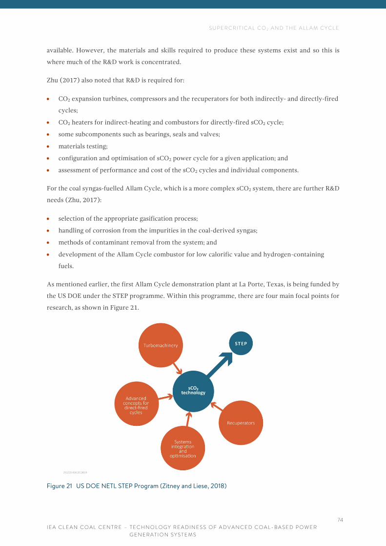
S U P E R C R I T I C A L C O 2 A N D T H E A L L A M C Y C L E
I E A C L E A N C O A L C E N T R E – T E C H N O L O G Y R E A D I N E S S O F A D V A N C E D C O A L - B A S E D P O W E R
G E N E R A T I O N S Y S T E M S
74
available. However, the materials and skills required to produce these systems exist and so this is
where much of the R&D work is concentrated.
Zhu (2017) also noted that R&D is required for:
• CO2 expansion turbines, compressors and the recuperators for both indirectly- and directly-fired
cycles;
• CO2 heaters for indirect-heating and combustors for directly-fired sCO2 cycle;
• some subcomponents such as bearings, seals and valves;
• materials testing;
• configuration and optimisation of sCO2 power cycle for a given application; and
• assessment of performance and cost of the sCO2 cycles and individual components.
For the coal syngas-fuelled Allam Cycle, which is a more complex sCO2 system, there are further R&D
needs (Zhu, 2017):
• selection of the appropriate gasification process;
• handling of corrosion from the impurities in the coal-derived syngas;
• methods of contaminant removal from the system; and
• development of the Allam Cycle combustor for low calorific value and hydrogen-containing
fuels.
As mentioned earlier, the first Allam Cycle demonstration plant at La Porte, Texas, is being funded by
the US DOE under the STEP programme. Within this programme, there are four main focal points for
research, as shown in Figure 21.
Figure 21 US DOE NETL STEP Program (Zitney and Liese, 2018)

S U P E R C R I T I C A L C O 2 A N D T H E A L L A M C Y C L E
I E A C L E A N C O A L C E N T R E – T E C H N O L O G Y R E A D I N E S S O F A D V A N C E D C O A L - B A S E D P O W E R
G E N E R A T I O N S Y S T E M S
75
As Figure 18 shows, the major challenges for sCO2 systems and the Allam Cycle are in the
improvements of turbomachinery and recuperators to cope with changes in operation which result
from the switch from steam/water to sCO2 as the working fluid for the turbine. Further challenges
relate to the oxyfuel combustion part of the process and the overall integration and optimisation of
the plant. The US Department of State has invested significant funds (US$30 million) into sCO2
cycle-related research.
Net Power, as discussed above, is invested in addressing several specific challenges for the coal-based
Allam Cycle, including corrosion from additional coal-fired impurities. This is an issue which is
common to all systems which fire coal-derived syngas instead of natural gas (Lu, 2016; see also IGCC
in Chapter 3). Additional work will be required to optimise SOx and NOx impurities; again, these are
issues that result from using coal syngas rather than natural gas as a fuel. Once sCO2 systems are
optimised for coal, further development will proceed to select syngas combustors which are suitable
for lower quality fuels as well as the most efficient gasification systems in terms of LCOE.
6.4.2 Economics
Since sCO2 and Allam Cycles are still largely developmental, there is limited information on the cost
of building and operating commercial plants. There is the suggestion that the Allam Cycle could replace
conventional turbine cycle systems in IGCC plants, increasing plant efficiency enough to offset the
loss of energy required for CCUS. Current IGCC systems have an LCOE of 70–100 US$/MWh. With
CCS this increases to 90–130 US$/MWh. The NET Power gas-fired Allam Cycle plant at La Porte,
(discussed earlier) is expected to have an LCOE of around 40 US$/MWh, in the same range as a
standard NGCC (without CCS) (Lu, 2016). Once commercialised, future plants will be pre-fabricated
resulting in lower on-site construction costs and shorter construction timelines.
6.4.3 Barriers to be addressed
In the IEA CCC report on sCO2, Zhu (2017) concluded that the success of the sCO2 cycle would rely
on overcoming challenges in terms of material science and engineering which would impact both the
technical feasibility of the technology as well as its economic viability. As mentioned, the greatest
challenges are likely to be in the optimisation of plant components which must operate under
challenging temperatures and pressures. And, as Zhu (2017) stresses, even when these challenges are
overcome for natural gas-fired sCO2 systems, further advances will be required to cover additional
obstacles due to the impurities in coal. Zhu suggests that there are several sCO2 cycles to consider and,
as yet, the optimum cycle has not been identified. Technologies for pilot and demonstration systems
will need to be produced which could ultimately lead to further modelling and development, before
sCO2 cycles are finally optimised. The Allam Cycle appears to be the most promising of the sCO2
options but even the this is still in its relative infancy of development. Whilst the Allam Cycle and
related sCO2 systems could be cheaper and cleaner than other coal-based utilities, this depends heavily
on the identification, and production of functioning components.

S U P E R C R I T I C A L C O 2 A N D T H E A L L A M C Y C L E
I E A C L E A N C O A L C E N T R E – T E C H N O L O G Y R E A D I N E S S O F A D V A N C E D C O A L - B A S E D P O W E R
G E N E R A T I O N S Y S T E M S
76
Lu (2016) summarised the development pathway for the Allam Cycle in Figure 22.
Figure 22 Allam Cycle development pathway (Lu, 2016)
The La Porte project comprises a consortium of research groups and equipment manufacturers who
will be working together to optimise design and functionality to prepare the technology for
commercialisation within the next 5–10 years. It is expected to deliver data which will help to optimise
many areas of sCO2 plant operation, as well as achieving an overall increase in efficiency (>10% over
current test results), and reductions in water use (>30%) and cost (>30%).
6.5 COMMENTS
sCO2 systems use the fluid dynamics of supercritical CO2 to operate turbines at greater efficiencies
than standard steam turbines. Various sCO2 systems have been under development for a decade or so
but the recent invention of the Allam Cycle appears to have significantly renewed interest in the sector,
with the US DOE suggesting that full-scale deployment could be achievable within 5–10 years.
The advantages of sCO2 systems are largely their high thermal efficiency and the related reduction in
emissions. They also have lower water use and will potentially have lower capital and operating costs,
once the processes are commercialised. Initial data suggest that, theoretically, a full-scale Allam Cycle
plant could be over 18% more efficient than an equivalent IGCC plant with CO2 capture.
sCO2 systems could replace steam cycles in numerous applications, working in nuclear and renewable
utilities and industries. Since they are more efficient, cleaner, more compact and potentially cheaper
than standard turbine systems, they could revolutionise the power industry, reducing power costs by
around 15%.
The biggest challenge for the sector is the production of advanced recuperative gas turbines and heat
exchangers. These systems are not currently available, but the skills required to produce them are and

S U P E R C R I T I C A L C O 2 A N D T H E A L L A M C Y C L E
I E A C L E A N C O A L C E N T R E – T E C H N O L O G Y R E A D I N E S S O F A D V A N C E D C O A L - B A S E D P O W E R
G E N E R A T I O N S Y S T E M S
77
it is possible that these technologies will be ready within the US DOE timeframe. However, that is not
to imply that this is not a significant challenge.
The sCO2 systems studied so far have been gas-fired. For coal-based sCO2 systems there is the added
challenge of producing clean coal-derived syngas for use within the systems – challenges that are
shared in related research activities such as those for IGCC, IGFC, and polygeneration. In terms of
economics, these plants could be cost effective once commercialised but significant investment is
required to get them to that stage.

S T A T I O N A R Y F U E L C E L L S
I E A C L E A N C O A L C E N T R E – T E C H N O L O G Y R E A D I N E S S O F A D V A N C E D C O A L - B A S E D P O W E R
G E N E R A T I O N S Y S T E M S
78
v
7 S T A T I O N A R Y F U E L C E L L S
Fuel cells are electrochemical systems which convert the chemical energy within a fuel directly into
electrical energy with no combustion. Since the conversion of heat, through turbines, to electricity is
one of the major areas for energy loss, the avoidance of this process significantly increases the system
efficiency. Therefore, a fuel cell using coal as the fuel would be far more efficient than a conventional
coal combustion plant, would produce minimal flue gas emissions, and the CO2 from the process could
be captured for CCUS. Because fuel cells can be clean running and efficient (up to 60% for electricity
production, and over 90% efficiency for combined heat and power systems), the potential demand for
large-scale fuel cells based on coal could be substantial.
There are hundreds of thousands of fuel cells in commercial operation, being popular in military and
industrial applications. However, these existing units are all small scale (1–250 kW) and none use coal
as the input fuel.
A recent report from the IEA CCC has described stationary fuel cells in detail (Zhang, 2018) and it is
recommended to the interested reader. This chapter focuses on the current state of development and
addresses the challenges and barriers to deployment of these systems on a larger scale.
7.1 PRINCIPLES OF THE TECHNOLOGY
Solid oxide fuel cells (SOFCs) produce electricity directly by oxidising a fuel by chemical oxidation
rather than oxidation through combustion. The chemistry of the oxidation can be controlled to allow
internal reforming (usually methane) which can be a heat-adsorbing reaction, reducing the need for
cooling of the system and, in turn, reducing parasitic system power loss. The exhaust heat from SOFC
systems can be high enough to enable combined cycle combinations with steam turbines. Further, the
air streams can be controlled and separated to facilitate carbon capture (OFE, 2018c).
An SOFC system is summarised in Figure 23. The cathode and anode electrodes are porous with an
electrolyte between them. The electrodes must be porous as it is dense oxygen ions which act as the
conductor within the electrolyte (ceramic) and between the electrodes. SOFCs can use both H2 and
CO (from gasification or reformation of hydrocarbon fuels). This means that fuels such as natural gas
and coal-derived syngas must be reformed with steam to produce H2 and CO (NETL, 2018b).

S T A T I O N A R Y F U E L C E L L S
I E A C L E A N C O A L C E N T R E – T E C H N O L O G Y R E A D I N E S S O F A D V A N C E D C O A L - B A S E D P O W E R
G E N E R A T I O N S Y S T E M S
79
v
Figure 23 Diagram of a SOFC (NETL, 2018b)
Current SOFCs use hydrogen or methane as the fuel. However, according to NETL, SOFCs are
fuel-flexible, and could work with some fossil fuel impurities, although desulphurisation would be
required.
Molten carbonate fuel cells (MCFC) use immobilised liquid/molten carbonate rather than ceramics as
the electrolyte and hydrogen or methane as the fuel, with internal reforming being possible. But again,
these systems are not currently operating with coal as the fuel feed and for this to happen the fuel cells
need to be specialised. Carbon-based fuel cells could have efficiencies up to 70%, increasing to 85% if
the waste heat is used in a cogeneration capacity. They also offer lower pollutant emissions, potential
for CCUS, and no need for water management, making them ideal for areas with water restrictions.
There are also alkaline fuel cells, phosphoric acid fuel cells, polymer electrolyte membrane fuel or
proton exchange membrane fuel cells, but these all currently only run with high-grade H2 as the fuel
(Zhu, 2015b).
There are two types of fuel cells which could use coal (Roberts and others, 2017):
• those that use coal in a gasified form, IGFCs (integrated gasification carbon fuel cells); and
• those that can use fuel in a solid form, DCFCs (direct carbon fuel cells).
These two systems are very distinct in their operation. IGFCs, as mentioned in Chapter 3, involve the
combination of the syngas from a coal gasification system with a fuel cell such as an SOFC. DCFC
systems currently under development are based on molten salt or molten carbonate as the electrolyte.
DCFC systems based on coal aim to oxidise completely the carbon in coal to CO2. For this, options
include solid carbon in a molten salt or in a fluidised bed reactor (Zhu, 2015b). Although this may
sound simple, the chemistry is still under development and the focus is on how to create continuous
contact between the solid fuel and the working electrode. DCFC systems are likely to be affected

S T A T I O N A R Y F U E L C E L L S
I E A C L E A N C O A L C E N T R E – T E C H N O L O G Y R E A D I N E S S O F A D V A N C E D C O A L - B A S E D P O W E R
G E N E R A T I O N S Y S T E M S
80
v
significantly by coal quality, requiring de-ashing, heat treatment, and acid washing of the coal before
use (Zhang, 2018).
DCFC systems require high operating temperatures (700–900°C) and therefore must be constructed
from materials that can handle this heat. The Idaho National Laboratories, USA, are working on a ‘true
direct carbon fuel cell’ which uses an electrolyte made of materials which can work at lower
temperatures (<600°C). The anode is made from fibres woven together to maximise surface area. The
system is currently at the developmental stage with prototypes at the scale of a watch battery
(SD, 2018).
Numerous types of DCFC have been proposed based on molten hydroxide, molten carbonate, direct
carbon solid oxide, and hybrid direct carbon fuel cells. However, these systems are still at the
theoretical stage and no demonstration plants have been planned. Options involving gasified (IGFC)
or pyrolysed coal are therefore receiving more interest than DCFC options (Zhang, 2018).
7.2 CURRENT DEPLOYMENT
According to IEA Fuel Cells (FC) (IEA Fuel Cells, 2013), there are many companies working in fuel
cell development and sales and most of the commercial systems are used in the following areas:
• mobile, military and strategic applications (<1 kW systems);
• auxiliary power units and back-up power (1–250 kW);
• stationary small-scale combined heat and power (1–5 kW); and
• stationary medium-large scale (0.1–10 MW).
Although the IEA FC list is a little dated, it is still a useful compilation of all the companies involved in
fuel cell development. Around 50,000 fuel cells units, amounting to over 185 MW in capacity, were
sold globally in 2014 and over 70,000 units (around 340 MW) in 2015 (Roberts and others, 2017).
MCFCs have been developed in several countries and single cell stacks can produce up to 2.8 MWe,
with a lifetime of five years. MCFCs have been used for baseload power at waste water treatment plants,
and industrial and commercial buildings (Zhu, 2015b).
The largest fuel cell facility is at the Gyeonggi Green Power Plant in South Korea which uses natural
gas. The plant is fully operational and uses 21 x 2.8 MWe Direct Fuel MCFCs to provide continuous
power to the local utility grid with an efficiency of 47% and emissions well below the limits for a gas
turbine.
Most of the commercially available fuel cell units have H2/CO as fuel, although some portable systems
use methanol or ethanol. To date, there are no coal-based fuel cells in operation. Current efforts are
focusing on development of the individual components of the technology (see below).

S T A T I O N A R Y F U E L C E L L S
I E A C L E A N C O A L C E N T R E – T E C H N O L O G Y R E A D I N E S S O F A D V A N C E D C O A L - B A S E D P O W E R
G E N E R A T I O N S Y S T E M S
81
v
7.3 FUTURE DEVELOPMENT
The number of operating fuel cells and fuel cell suppliers in the EU is currently significantly lower
than in the USA (Zhang, 2018). However, the EU established a European Fuel Cell and Hydrogen Joint
Undertaking programme (FCH JU) in 2008 with the aim of commercialising the technologies from
2020 onwards. By 2017, €180 million had been invested in 49 projects and, as a result, the EU now
claims to be a world leader in SOFC (Aguilo-Rullan and others, 2017).
The US DOE is investing US$13.5 million in 16 projects to advance SOFC research and development.
There are two major projects which will be managed by NETL (OFE, 2018b):
• Fuel Cell Energy Inc, Danbury, CT, USA, is developing a conceptual design for a MW-scale SOFC
(unnamed fuel). The project includes a cost analysis which aims to demonstrate that the cost of
such a system will be <US$6000 (kWe) at low-volume production levels; and
• LG Fuel Cell Systems Inc, North Canton, OH, USA is also performing a techno-economic analysis
of a MWe-scale natural gas-fired system.
The remainder of the US DOE funding is for projects which concentrate on the basic requirements for
fuel cell operation, such as cathode development, capture of trace elements (which may poison
cathodes), circuit materials and gas sensors. However, the focus of the US DOE’s Fuel Cell Technology
Office appears to be on gas- and biogas-fuelled systems rather than coal (Zhang, 2018).
As noted by the IEA FC (2017), because the SOFCs in production are small, their market is very
different to that of a large-scale power system. To move into power production at the scale of a power
plant (20–1000 MW) will require further development and the resulting plants may be in the form of
systems that operate in a combined format. For example, Figure 24 shows a coal-based pressurised
IGFC. This is a conventional coal gasification system combined with a SOFC cell. The system will have
low water use, 99% carbon capture, and 50% efficiency.

S T A T I O N A R Y F U E L C E L L S
I E A C L E A N C O A L C E N T R E – T E C H N O L O G Y R E A D I N E S S O F A D V A N C E D C O A L - B A S E D P O W E R
G E N E R A T I O N S Y S T E M S
82
v
Figure 24 Coal-based pressurised IGFC system (IEA FC, 2017)
Systems such as that in Figure 21 are being developed by Bloom Energy, Delphi, MHI, LG Fuel Cell
Systems and Versa Power Systems. However, according to Zhang (2018), current research into IGFC
systems is focused on theory – the high cost of prototypes, even at laboratory scale, makes full-scale
demonstrations an economic challenge. The US DOE has established SECA, the Solid-State Energy
Conversion Alliance, which aims to have a 10 MW IGFC demonstration plant running by 2020 and to
reach 50 MW by 2025.
As mentioned in Chapter 2, the Osaki CoolGen project in Japan plans to initiate the world’s first
coal-based IGFC plant in 2021. The plant, which operates as an oxygen-blown IGCC, is being converted
into an IGFC plant with a target efficiency of 55% and CO2 capture. China Huaneng’s GreenGen project,
also discussed in Chapter 2, has a similar plan for upgrading from an IGCC plant to an IGFC plant but,
to date, no conversion construction work has begun.
MHI have proposed the concept of an SOFC triple-combined system – IGTC (Integrated Gasification
Triple Cycle) comprising an SOFC with a gas turbine and a steam turbine. The IGTC could have a net
thermal efficiency of over 51% and a lower CO2 production rate. There is also the proposal of a super
IGFC which combines an SOFC with a steam gasifier. This is still a theory and is far from demonstration.
However, it does promote the concept of retrofitting syngas SOFC systems to existing power plants.
A pilot project retrofitting an SOFC to a closed IGCC plant in the Netherlands was tested in 2017
(IGFC-CC STEX). The data demonstrated that such retrofitting was possible and could boost electrical
and heat efficiencies, but would require ‘major’ process modification, especially in the gas turbine and
heat recovery steam generator (Zhang, 2018).
The review by Zhang (2018) mentioned a few other potential applications for fuel cells in combination
with coal-based energy. For example, MCFC fuelled with methane could be used in coal plants to help

S T A T I O N A R Y F U E L C E L L S
I E A C L E A N C O A L C E N T R E – T E C H N O L O G Y R E A D I N E S S O F A D V A N C E D C O A L - B A S E D P O W E R
G E N E R A T I O N S Y S T E M S
83
v
with CO2 capture – the exhaust gas from a gas turbine could be fed into the fuel cell and the system
would provide additional heat and power to give it an advantage over other CO2 capture systems.
Another proposal is to combine underground coal gasification (UCG) with IGCC and SOFC. However,
both these proposals are still very much theoretical.
7.4 CHALLENGES
Most of the work on fuel cells is focused on materials performance and cost. However, to date there
are no coal-based fuel cells in operation or even at demonstration scale and so those research groups
who are interested in using coal as the fuel must predict potential issues that may arise when coal is
used instead of natural gas or similar, cleaner, gases. The sections below summarise the general
challenges for all fuel cells whilst trying to identify issues which may be particularly relevant to coal-
based systems.
7.4.1 Technology
As mentioned earlier, the current focus of US research is on improving the reliability of fuel cell
systems and components – reducing the degradation rate and production costs. One of the major
challenges of SOFCs is ensuring the continuous feed of the fuel to the anode. Corrosion and
decomposition of materials within the cells appears to be a significant issue, over and above the overall
complexity of the process. Materials development will be the major focus of many R&D projects in the
sector. Continuous fuel feed mechanisms also need to be developed to ensure that the cells work
continuously without interruption (Zhang, 2018).
NETL (2018) are working on SOFCs and their plan for R&D in this area is summarised in Figure 25.
Figure 25 R&D map for NETL SOFC development (NETL, 2018b)
Current R&D efforts focus on maximising the electrochemical performance and durability of cells
which means work to improve cell power density and robustness, to reduce degradation, and to keep
costs down. Significant work is also required on advanced materials (NETL, 2018b).

S T A T I O N A R Y F U E L C E L L S
I E A C L E A N C O A L C E N T R E – T E C H N O L O G Y R E A D I N E S S O F A D V A N C E D C O A L - B A S E D P O W E R
G E N E R A T I O N S Y S T E M S
84
v
Brandon (2011) suggested that the key challenges for SOFC in the near term are to create durable
systems under real world operating conditions. The longer-term challenges relate to enabling fuel cell
systems to work with renewable or low-carbon fuels, reducing costs, extending device performance
and lifetime.
Zhang (2018) considered the technical limitations of DCFCs, which include poor power density, high
degradation rates, complex fuel feed systems, challenges with scaling up and potentially complex fuel
processing procedures (cleaning and processing of coal). All these issues will have to be addressed in
large pilot or small demonstration phase projects.
Coal-based fuel cells are likely to be most suited for baseload applications as they will require thermal
insulation and could have ‘very slow’ start-up and shut-down, poor load-following capability and no
power at cold start (Roberts and others, 2017).
In simple terms, using a complex solid such as coal causes three main issues for direct use in fuel cells:
• it is a solid and therefore cannot diffuse anywhere unless it is converted into a molten salt or
gasified;
• unless removed prior to use, the ash in coal can cause cell degradation. Removal of the ash prior
to use can be costly; and
• the sulphur in coal, along with other trace pollutants, can affect the integrity of the system and
speed up deactivation.
Jiang and others (2017) published an excellent review of the technical challenges of DCFCs, providing
Figure 26 as an indication of the ways to introduce coal as a fuel in a fuel cell format.
Figure 26 Different contact modes of solid carbon with the anode in DCFC systems (Jiang and others,
2017)

S T A T I O N A R Y F U E L C E L L S
I E A C L E A N C O A L C E N T R E – T E C H N O L O G Y R E A D I N E S S O F A D V A N C E D C O A L - B A S E D P O W E R
G E N E R A T I O N S Y S T E M S
85
v
The crystal structure, surface properties and particle size of solid fuels such as coal clearly pose a
challenge for the basic functionality of the system. According to Roberts and others (2017), the coal
used in fuel cells will need to be processed to remove volatiles and ash before it can be fed into a solid
or fluid delivery system. The amount and type of processing required will vary with the coal type and
ash content. CSIRO in Australia has been focusing on coal preparation for use in DCFC systems and
suggests that Victorian brown coals show promise since they have low sulphur and low ash contents
along with elevated levels of catalytic elements. Similar Chinese studies suggest that Indonesian
subbituminous coals may also be appropriate. KEPRI in Korea have shown that DCFC performance
increases when using ash-free coal (Zhang, 2018).
For coal-based IGFC systems, the focus is catalytic gasifier improvements along with improvements
in stack unit reliability (when operating with high methane syngas) and oxyfuel combustion
technologies (Zhang, 2018).
7.4.2 Economics
For currently commercial fuel cells (non-coal systems), most sales have been facilitated through
incentives and tax credit schemes. For example, in the USA there are national tax incentives for fuel
cell purchases as well as State incentives such as the Self-Generation Incentive Program in California.
In Japan, fuel cells are produced by commercial suppliers who have sold several hundreds of thousands
of units into the national market, largely due to government subsidies. Similarly, in South Korea, the
national government subsidises 80% of the purchase price with a further 10% being available from
local government. Because of these financial incentives, South Korea now has the largest fleet
(by MW) of stationary fuel cells. South Korea is also the host for the 59 MW Gyeonggi Green Energy
park, mentioned above. Interestingly, China appears to be lagging somewhat in its fuel cell investment,
with little happening in fuel cell R&D. Even with all these incentives, many fuel cell systems are unable
to recover costs within their operating lifetimes. Operating prices in the USA in 2013 ranged from
3,000–21,000 US$/kW (without incentives). Prices will drop over time as the technology improves
and if systems can be developed that run on coal, then costs will reduce even further (Zhang, 2018).
In their review of CFCs, Roberts and others (2017) concluded that indirect fuels cells with thermally
integrated gasifiers (IGFC) with molten or SOFC technology are likely to be the first coal-based
systems to be commercialised. Further, IGFC systems are likely to be more cost-effective than
alternative coal-based fuel cells. The efficiency of these systems (perhaps twice that of conventional
pulverised coal fired plants with CCS) coupled with significantly reduced emissions is likely to be the
main driver towards commercialisation. Once these systems are proven through practical
demonstrations, scaling up to large-scale power generation level will be achieved through the stacking
of modular units.
As mentioned, current research on coal-based SOFC system is focused on theory. Prototypes, even at
laboratory scale, make full-scale demonstrations an economic challenge. Zhang (2018) confirms that

S T A T I O N A R Y F U E L C E L L S
I E A C L E A N C O A L C E N T R E – T E C H N O L O G Y R E A D I N E S S O F A D V A N C E D C O A L - B A S E D P O W E R
G E N E R A T I O N S Y S T E M S
86
v
IGFC systems should eventually be economically competitive with other technologies. Plant costs for
an IGFC with direct CCS could be around 25% higher than for a conventional pulverised coal fired
plant with CCS but the cost per kW for energy production could be around 25% lower. However, the
adoption of IGFC and other coal-based fuel cell systems relies on the successful demonstration of
projects such as CoolGen.
Roberts and others (2017) state that the current level of investment for DCFCs is “very low and mostly
at academic level” and so “it will take a long time before DCFCs are likely to be commercialised.”
Section 7.3 emphasised the significant US DOE investment in fuel cell technology. However, most if
not all of these projects focus on specific components of fuel cells rather than total fuel cell systems.
By ensuring that all the individual parts of the fuel cell are adequate for purpose, then the move
towards demonstration and commercialisation will be much smoother.
7.4.3 Barriers to be addressed
Although small-scale gas-powered fuel cells are commercially available, they differ significantly from
fuel cells which could be part of a power producing utility. The systems need to become more reliable,
durable, and significantly cheaper. However, one advantage of fuel cells is that, once this happens,
scaling up could be achieved by stacking many small modular systems in one location. Zhang (2018)
states that the main factors to be addressed for utility-scale fuel cell penetration into the market are:
• reducing costs, to be competitive with other technologies;
• fuel selection and associated supply chain infrastructure; and
• demonstrating sufficient durability.
More investment is needed in advanced manufacturing, in materials, catalysts, membranes and
electrolytes – all the basic components that will ensure that fuel cells become reliable. Once these
fundamental issues are addressed, then it may be possible to scale-up fuel cells toward utility scale.
Even then, issues with hydrogen fuel or syngas production, storage, delivery, and related infrastructure
will need to be addressed. Zhang (2018) concludes that government support is critical to progress fuel
cell technologies to the stage where they are ready to enter the market.
With respect to coal-powered fuel cells, the barriers include all those listed previously for gas-power
fuel cells along with the not insignificant challenge of producing an extremely clean, mobile fuel from
a complex, solid material. The most promising option for coal is the use of gasified coal in IGFC, with
possibly two plants being developed currently. Solid coal-based systems, such as DCFCs are still at a
very early development stage.
7.5 COMMENTS
Fuel cells have the potential to produce power efficiently – up to 90% efficiency in a combined heat
and power system. They are clean, with no pollutant emissions to the atmosphere, and consume

S T A T I O N A R Y F U E L C E L L S
I E A C L E A N C O A L C E N T R E – T E C H N O L O G Y R E A D I N E S S O F A D V A N C E D C O A L - B A S E D P O W E R
G E N E R A T I O N S Y S T E M S
87
v
significantly less water than a conventional power plant. However, there will be significant fuel clean
up required before coal can be used in a fuel cell. Fuel cells can be produced in small modular units
which can then be stacked for great output and would therefore be ideal for modular type applications
in remote, emerging regions. Gas-fired fuel cells are commercially available. However, these systems
are small, complex and expensive, with their own challenges with respect to durability and reliability.
Fuel cells are like batteries – they require the movement of molecules to work. Currently, the fuel cell
market is based on systems working with gaseous fuels. Coal is not a gas and, when it is turned into a
gas, it is not initially a clean gas. And so, the first fuel cells using coal which are under development
plan to use gasified coal. Such systems therefore must combine coal gasification systems with the
challenges of fuel cell systems, and the challenge of cleaning up the syngas to ensure that these two
systems can work together. The first demonstration-scale IGFC (integrated gasification fuel cell)
systems based on gasified coal are planned to be operational in Asia by 2021. The success of these
demonstrations will have a significant impact on the future development of IGFC systems.
Alternative fuel cell options for coal include DCFCs (direct carbon fuel cells). However, these systems
would require coal to be processed to remove all impurities (ash, sulphur, trace elements), thus adding
a significant layer of processing and relating cost. For the moment, DCFC systems remain theoretical.

O T H E R S Y S T E M S
I E A C L E A N C O A L C E N T R E – T E C H N O L O G Y R E A D I N E S S O F A D V A N C E D C O A L - B A S E D P O W E R
G E N E R A T I O N S Y S T E M S
88
8 O T H E R S Y S T E M S
This chapter looks at alternative coal to energy systems not included in the previous chapters. These
systems have been reviewed in more detail in previous IEA CCC reports (Zhu, 2015a,b; Lockwood,
2016; Mills 2017).
8.1 CHEMICAL LOOPING
Chemical looping combustion (CLC) is a system in which oxygen in air is transferred to the fuel
through a solid oxygen carrier which is circulating (looping) between two interconnected fluidised
bed reactors – one for fuel and one for air, as shown in Figure 27.
Figure 27 Chemical looping process (MFS, 2018)
Solid particles circulate through the loop, oxidising in the air, and then passing to the fuel zone where
they subsequently oxidise the fuel. Materials such as copper, iron or nickel are used as the oxygen
carrier particles. Because the CO2 and N2 are in different exhaust streams, the system is suitable for
CCUS. The system can also be operated to produce hydrogen or syngas as well as power.
CLC systems can, to some extent, use in-situ gasification as well as gaseous fuels if there is some form
of movement of the oxygen. In chemical looping with oxygen uncoupling (CLOU), the carrier releases
gaseous oxygen. Alternatively, in gasification looping, coal is gasified via a stream of steam or CO2
which also fluidises the nickel carrier in the reactor. This syngas then reacts with the oxygen carriers
and is fully oxidised.

O T H E R S Y S T E M S
I E A C L E A N C O A L C E N T R E – T E C H N O L O G Y R E A D I N E S S O F A D V A N C E D C O A L - B A S E D P O W E R
G E N E R A T I O N S Y S T E M S
89
NETL in the USA currently has three pilot-scale looping systems (a single fluid bed, a 50 kWth
chemical looping reactor and a cold flow looping reactor) for validation and calibration of their
ongoing modelling programme (MFS, 2018).
GE, Alstom and the Los Alamos National Laboratories, USA, are all working on chemical looping
projects which are still at pilot scale (Zhu, 2015b). There appears to be only one 3 MWth
demonstration plant produced by Alstom (now GE), although this seems to have ceased operation.
The plant used CaSO4 as the carrier (generated in situ from limestone) (Wolfersdorf and Meyer, 2017).
Experimental research is underway at Ohio State University at 250 kW scale (Wolfersdorf and Meyer,
2017). The Ohio plant is a coal-fired chemical looping (CDCL) system using FeO2 as the carrier
(Zhu, 2015b). As of March 2017, the 25 kWth sub-pilot plant had run for over 1000 hours, testing a
selection of fuels from anthracite to lignite. Further testing in a larger, 250 kWth, pilot unit is underway
with Babcock and Wilcox carrying out a feasibility study for the upscaling of advanced combustion
design and control features which have been developed at the sub-pilot unit (Energy.gov, 2018).
Building from these pilot studies, the US DOE has invested over US$740,000 in a 10 MWe coal direct
chemical-looping demonstration plant at the Dover Light and Power Plant in Dover, OH, USA. Based
on the early success of the pilot work in the Ohio State University, the 10 MWe demonstration could
commence as early as 2020 (CBE, 2017).
The Hy-Pr-Ring Process in Japan proposed the use of coal gasification with chemical looping to create
H2 and CH4. The efficiency of the process is estimated at 77% (HHV) for H2 production (Zhu, 2015b).
NEDO, Japan, has a target period of 2025-30 for establishment of chemical looping combustion. The
NEDO concept is for 100–500 MW power stations, net efficiency of 46% with no separate CO2 capture
unit or system being required nor any loss of plant efficiency due to the CO2 capture (Yasui, 2014).
No recent updates have been found on the status of this project.
The advantage of CLC systems over conventional combustion is the CO2 capture potential – the energy
penalty for CO2 capture at a CLC plant is 9% compared to 25% for an equivalent scale oxyfuel
combustion plant. Economic modelling of a theoretical 550 MW coal-based plant has suggested that
CLC would increase the cost of electricity by 28.8% but would remove 96.5% of the CO2. This exceeds
the target set by the US DOE of 90% CO2 capture with an increase in electricity cost of under 35%
(Valazquez-Vargas and others, 2014).
According to the IEA CCC review by Zhu (2015), significant work has been carried out within the EU
on CLC systems. The current research focus on CLC is on the development and testing of potential
oxygen carriers for within the loop. Finding a material that is reactive, and a stable oxygen carrier
appears to be difficult. Further, since the carriers can be lost in the ash, the material must be
inexpensive (such as limestone or iron oxide). There are also technical challenges related to running

O T H E R S Y S T E M S
I E A C L E A N C O A L C E N T R E – T E C H N O L O G Y R E A D I N E S S O F A D V A N C E D C O A L - B A S E D P O W E R
G E N E R A T I O N S Y S T E M S
90
two large, linked, fluidised bed systems and the potential of leakage/seepage of materials from or
between the beds.
8.2 HYBRID SYSTEMS
A hybrid system is one which takes in two or more forms of energy as the power source but does so
whilst keeping the fuels separate. This could mean a system which uses heat from renewable power
feeding into a plant which is firing coal. It would not include coal and biomass cofiring or any other
cofiring systems where the fuels are combined.
Most of the coal hybrid systems in the literature concentrate on coal combustion or gasification
systems which accept extra energy as heat or power from sources such as wind or solar. Renewable
energy systems have the potential to feed directly into the power cycle of coal plants either as heat or
electricity. Solar power can be introduced into a system in two forms – as heat, and as electrical power
from photovoltaic (PV) units. For conventional coal combustion systems, solar generated steam can
be channelled directly into the main turbines. This steam is usually 300–400°C, lower than the 500°C
for most large steam powered plants and so there is some work to be done to match the feed into the
combined system effectively. Solar power can also be used to raise feedwater temperature. Solar power
for heat input to steam or feedwater systems at coal plants has been shown to be more efficient than
heat production from solar systems alone. The saving in coal-use for the plant will be reflected in lower
fuel costs and lower emissions (Zhu, 2015b).
A more recent IEA CCC report (Mills, 2017) looked at coal-solar hybrid systems, listing the four main
ways solar power can be used within a coal plant:
• preheating of high pressure feedwater (boost mode);
• additional heating of feedwater (coal saving mode);
• heating of low pressure feedwater (boost mode); and
• production of steam (coal saving mode).
Currently, solar-coal hybrid systems seem to be gaining most interest. Since solar power is diurnal and
seasonal, with additional variations due to weather, units working with additional feed from solar
systems must be able to cope with this fluctuation. Solar thermal systems are currently relatively
expensive to install, in terms of capital costs, and so hybrid systems will need to take this additional
cost into account when calculating the benefits.
Further, solar-coal hybrids are tempting in terms of the ‘greening’ potential they offer to existing and
new coal plants, offsetting carbon use and reducing emissions. Since solar power tends to peak at
periods of high power demand, it has the potential to augment power output when prices are high.
Solar systems are often quick to install, employ local expertise and are often considered more
acceptable by the public and investors. However, solar PV systems are expensive, their output is

O T H E R S Y S T E M S
I E A C L E A N C O A L C E N T R E – T E C H N O L O G Y R E A D I N E S S O F A D V A N C E D C O A L - B A S E D P O W E R
G E N E R A T I O N S Y S T E M S
91
sporadic, they take up significant land space and, with respect to total hybrid plant output, their
contribution is low (possibly up to 30–40% solar share for a new, purpose-built plant) (Mills, 2017).
In the USA, Xcel Energy built a demonstration plant (Cameo Power Station, Colorado) combining a
44 MW coal-fired unit with a 4 MW concentrated solar power (CSP) unit. The CSP comprises a
6.4-acre (25,900 m2) solar field. The project ran for one year in 2010 and, during that time,
demonstrated that generation increased by 300 kW, and the heat rate reduced by 1.33–1.38% due to
the solar input. Total coal savings amounted to around 240 t for the duration of the study. Although
the plant had no reported technical issues, operation has stopped, and no further units appear to be
planned. A similar coal-CSP hybrid was planned as the Sundt Solar Boost Project, operated by Tucson
Electric Power and Areva Solar (Zhu, 2015). However, the project was abandoned before construction
began, due more to funding issues than technical ones (Wesoff, 2014; Mills, 2017). Similarly, the
Escalante Station (NM, USA), the Mayo Plant (NC, USA) the Kogan Creek Solar Boost project
(Australia), and Collinsville Power (Australia) have been abandoned (Mills, 2017; Arena, 2018). The
2 GW solar-coal hybrid Liddell Power Station, in New South Wales, Australia, ran from 2013 until
2016 and closed due to technical and contractual issues (Mills, 2017).
There was a project underway in Chile at the Mejillones plant where an existing 320 MW plant was to
be integrated with a solar unit (5 MW) producing superheated steam (Mills, 2017). However, the
Chilean government has announced that coal use for power generation is to be phased out, and that
no new plants are to be built without CCS. However, existing coal stations may remain part of an
important, flexible, energy mix (Patel, 2018). It is not clear how this move away from coal will affect
the Mejillones plant, which was due to be commissioned before the end of 2018 (Burton, 2018).
Interest is also being shown in coal-hybrid projects in South Africa, where Eskom have studied the
potential for solar input to all operational plants. The most promising option seems to be the new
Medupi supercritical plant. However, financial and bureaucratic issues have delayed any movement
towards deployment to date. Although solar-coal hybrid projects have also been considered in
Macedonia, the EU, and China, so far there are no projects under development in these regions.
India seems to be the only country with an active coal-solar project, the Dadri power station, where
solar thermal energy will be used to heat feedwater into the existing coal-fired plant (Sinha, 2017).
Solar power can be used almost anywhere where heat can be used to offset energy input. The IEA CCC
report by Zhu (2015) noted proposed (hypothetical) concepts for integrating solar with
magnetohydrodynamics, IGFC and SOFC systems. Kaniyal and others (2013) modelled the potential
for a polygeneration system producing liquid fuels and electricity via the atmospheric pressure solar
gasification of coal. Since coal gasification reactions require energy input, solar power could
theoretically provide this energy with reduced CO2 emissions. Solar energy has already been used to
boost the output of chemical gasification systems. A 300 kW pilot-scale reactor was built in Australia
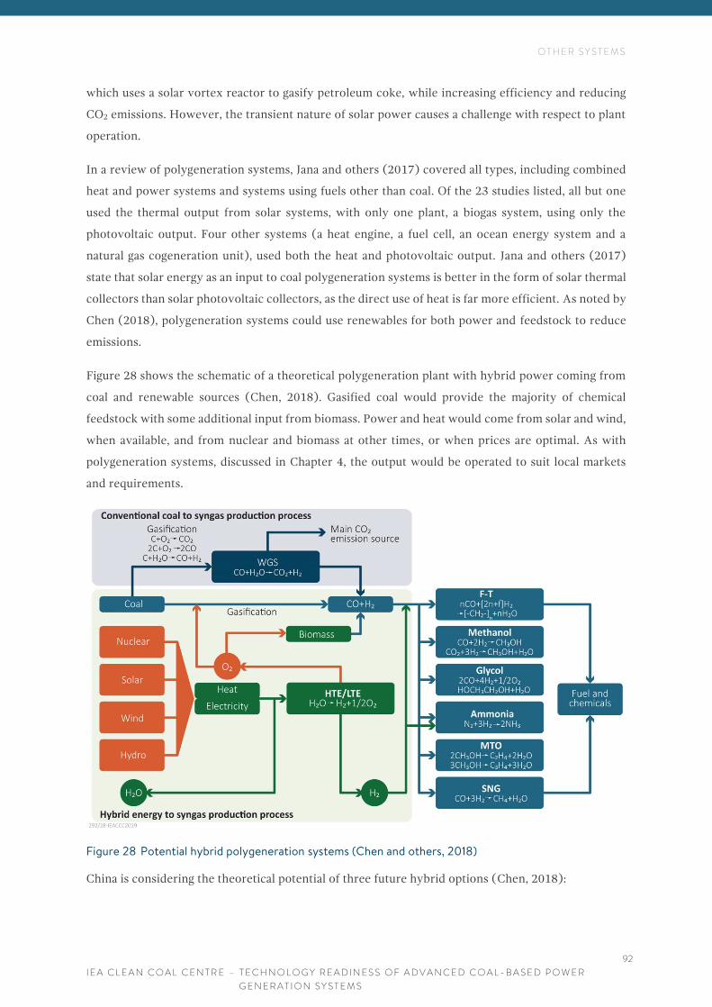
O T H E R S Y S T E M S
I E A C L E A N C O A L C E N T R E – T E C H N O L O G Y R E A D I N E S S O F A D V A N C E D C O A L - B A S E D P O W E R
G E N E R A T I O N S Y S T E M S
92
which uses a solar vortex reactor to gasify petroleum coke, while increasing efficiency and reducing
CO2 emissions. However, the transient nature of solar power causes a challenge with respect to plant
operation.
In a review of polygeneration systems, Jana and others (2017) covered all types, including combined
heat and power systems and systems using fuels other than coal. Of the 23 studies listed, all but one
used the thermal output from solar systems, with only one plant, a biogas system, using only the
photovoltaic output. Four other systems (a heat engine, a fuel cell, an ocean energy system and a
natural gas cogeneration unit), used both the heat and photovoltaic output. Jana and others (2017)
state that solar energy as an input to coal polygeneration systems is better in the form of solar thermal
collectors than solar photovoltaic collectors, as the direct use of heat is far more efficient. As noted by
Chen (2018), polygeneration systems could use renewables for both power and feedstock to reduce
emissions.
Figure 28 shows the schematic of a theoretical polygeneration plant with hybrid power coming from
coal and renewable sources (Chen, 2018). Gasified coal would provide the majority of chemical
feedstock with some additional input from biomass. Power and heat would come from solar and wind,
when available, and from nuclear and biomass at other times, or when prices are optimal. As with
polygeneration systems, discussed in Chapter 4, the output would be operated to suit local markets
and requirements.
Figure 28 Potential hybrid polygeneration systems (Chen and others, 2018)
China is considering the theoretical potential of three future hybrid options (Chen, 2018):

O T H E R S Y S T E M S
I E A C L E A N C O A L C E N T R E – T E C H N O L O G Y R E A D I N E S S O F A D V A N C E D C O A L - B A S E D P O W E R
G E N E R A T I O N S Y S T E M S
93
• nuclear assisted coal-based hybrid polygeneration systems: reduces coal consumption by 52%,
reduces CO2 production by 93% and can produce liquid fuel;
• solar/wind assisted – will also reduce coal consumption and CO2 emissions and could be
economically feasible in coastal areas, especially when carbon taxes are high; and
• hybrid energy system coal chemical industry – the physical siting of nuclear, coal and wind
systems in China could be good for the implementation of hybrid systems.
Chen and others (2018) estimated that hybrid systems could lead to the annual reduction of
1200 MtCO2/y emissions in coal-rich countries. Focusing on China, Figure 29 shows the potential for
hybrid systems across the country. By comparing the locations of the greatest CO2 emitters with the
major power plants and energy sources with the regions of chemical production, the study proposed
locations for potential hybrid polygeneration plants.

O T H E R S Y S T E M S
I E A C L E A N C O A L C E N T R E – T E C H N O L O G Y R E A D I N E S S O F A D V A N C E D C O A L - B A S E D P O W E R
G E N E R A T I O N S Y S T E M S
94

O T H E R S Y S T E M S
I E A C L E A N C O A L C E N T R E – T E C H N O L O G Y R E A D I N E S S O F A D V A N C E D C O A L - B A S E D P O W E R
G E N E R A T I O N S Y S T E M S
95
Figure 29 Feasible implementation of various hybrid systems based on the geographical distribution of
energy resources (Chen and others, 2018)

O T H E R S Y S T E M S
I E A C L E A N C O A L C E N T R E – T E C H N O L O G Y R E A D I N E S S O F A D V A N C E D C O A L - B A S E D P O W E R
G E N E R A T I O N S Y S T E M S
96
The integration of solar, wind and natural gas with coal would be most suited to the northwest of China
whereas coal and biomass integration would thrive best in the east-central areas. The eastern coast
would be the best locations for the integration of nuclear, wind and coal.
China is perhaps one of the most suitable locations for such systems due to the population growth, the
availability of coal, the chemical manufacturing base and the growing need for energy production. The
production of SNG within China is growing significantly. Chen and others (2018) suggest that
>900 MtCO2/y reduction could be achieved in 2020 if global coal-to-chemical systems used hybrid
technologies and that this could increase to 1.5 billion tonnes by 2030; China could contribute up to
80% of this due to the rapid growth in the region. At current costs for nuclear, wind and solar energy,
switching to hybrid systems would incur a cost penalty. For example, total operational costs could be
4–38% higher for nuclear systems compared to conventional coal-based ones. However, costs for
nuclear and renewable systems could come down significantly, making these systems more
economically viable, especially if carbon pricing becomes more favourable. Based on current
electricity prices, if the carbon tax >26.2 US$/tCO2-e then nuclear energy hybrid coal-to-methanol
systems become competitive. Carbon prices need only be >11.4 US$/tCO2-e for wind integrated
coal-to-methanol systems to become competitive. Solar systems will take longer to become affordable.
The study by Chen and others (2018) is a theory of what could occur. However, the authors concede
that there are issues to be addressed with nuclear safety and waste, the intermittency of wind and solar
systems, and the long-term stable supply of biomass.
Mills (2017) concluded that there were several challenges to the deployment of coal-solar hybrids –
political, technical and financial. The competitiveness of these plants will be determined on a
case-by-case basis, depending on local space, reliability of sunlight, national energy mix and so on.
Technical challenges such as heat imbalances at the turbines and heat exchangers would also need to
be overcome. However, Mills (2017) concluded that the largest challenge was simply economic
viability in a competitive energy market and that coal-solar hybrids could find ‘useful niche markets’.
Although most projects proposed to date were at existing coal plants, the largest potential appears to
be for the integration of solar with coal at the design phase, which would allow the optimisation of
both feeds into the energy system.
8.3 COMMENTS
Chemical looping (CLC) is an alternative to standard combustion as it uses gasified coal in electrical
systems, releasing power through chemical oxidation. Although still currently pilot scale, CLC could
be moving towards a 10 MW demonstration scale within the next decade.
Hybrid electricity systems combine two distinct sources of energy such as solar with coal or wind with
coal. Unlike many of the other systems mentioned in this report, hybrids could already be at
commercial scale. However, deployment of hybrid systems is very site- and case-specific. Since hybrid

O T H E R S Y S T E M S
I E A C L E A N C O A L C E N T R E – T E C H N O L O G Y R E A D I N E S S O F A D V A N C E D C O A L - B A S E D P O W E R
G E N E R A T I O N S Y S T E M S
97
plants combine renewable energy with coal, they will have the same challenges as most renewable
systems – the input from the renewable side will be intermittent and will be weather and location
dependent. The most feasible hybrid option appears to be the combination of solar power with coal,
where the power from solar, either electric or thermal, is used to offset heating requirements for
feedwater. Although this has been shown to be technically feasible in several full-scale demonstrations,
the uptake of such an option seems to be more of an economic or logistical issue than a technical one.
Until the cost of PV units comes down, the combination of coal with solar may not be tempting to
investors.
As a nation, China is showing the most interest in hybrid systems. There are plans for potential
polygeneration facilities where coal would be used for both chemical feedstock and power but with
additional power supplied by solar and wind. There has also been a proposal for a hybrid networking
scheme across the whole country which would link solar, wind and nuclear production areas with coal
power plants and industrial chemical production regions. At the moment, this plan is theoretical but
could be the basis for similar large geographical-scale concepts in future, where regions coordinate
chemical and electricity production to try and combine the two for mutual benefit, economically and
environmentally.

C O N C L U S I O N S
I E A C L E A N C O A L C E N T R E – T E C H N O L O G Y R E A D I N E S S O F A D V A N C E D C O A L - B A S E D P O W E R
G E N E R A T I O N S Y S T E M S
98
9 C O N C L U S I O N S
The move to more efficient and cleaner production of power is a universal goal. And coal remains an
important part of the energy mix for many countries. There is therefore significant investment into
R&D of advanced coal-based power generation systems to ensure that the coal power generation
systems of the future are high efficiency, low emissions (HELE) technologies.
The technologies reviewed in this report are quite distinct in their operation and each is at a different
stage of deployment. Based on the conclusions of each chapter of this report, a progress graph has been
produced showing the approximate status of each, see Figure 30. This graph is based on Figure 2, the
‘Valley of Death’ from Chapter 1.
Figure 30 Status of deployment of advanced coal-based power systems
USC technology is fast becoming the system of choice in emerging economies that can afford to invest
in cleaner systems, such as China. Although AUSC is, theoretically, simply an advancement of USC to
higher temperatures and pressures, this advancement is still a significant challenge. The metals and
alloys required to cope with the stresses of high temperature and pressure combustion are becoming
available but, for utilities to invest in a full-scale plant, further testing and proof of suitability and
reliability is required as well as investment in escalated rates of production.
Hybrid power generation, combining the heat/power from renewable systems with coal, is
technically the most achievable of the systems reviewed in this report, as these systems are both
commercially available, separately, and the combination of both is achievable. The economics and the
site-specific applicability of such systems appear to be the main reasons that hybrid systems are not
deployed currently. These systems could be suitable for countries such as India and China but would
require the coordination of several different agencies, vendors, and utilities to move into reality.

C O N C L U S I O N S
I E A C L E A N C O A L C E N T R E – T E C H N O L O G Y R E A D I N E S S O F A D V A N C E D C O A L - B A S E D P O W E R
G E N E R A T I O N S Y S T E M S
99
IGCC systems, which gasify coal to produce power in a combined cycle manner, have had several
failed projects but full-scale plants are under construction in Japan and China. The success of these
two plants will be crucial for the determination of whether IGCC systems are deployed more
universally. Whilst IGCC systems are cleaner and more efficient than conventional coal combustion
systems, they are currently extremely costly. Their advantage over state-of-the-art systems such as
ultrasupercritical coal combustion is largely their easy applicability for CCUS. But the addition of
carbon capture technologies to IGCC plants could see their net efficiencies drop by 7–11%, reducing
their inherent efficiency advantage. However, this drop is lower than that which would be seen with
conventional plants combined with CCUS. And so, the economic success of IGCC is dependent on the
carbon price.
Polygeneration is the combined production of power and chemicals from coal. Plants producing each
of these products individually are commercially available; it is the combination of these two processes
into one flexible plant which causes difficulties. Ideally a polygeneration plant would produce power
when electricity costs are high and switch to chemicals or SNG production when the costs for these
rise. However, in reality, a polygeneration plant will exist in a region where one of these products
offers a distinct economic advantage over the other. In the cases reviewed in this report,
polygeneration plant projects have either stalled, been abandoned, or have been diverted to one
product only; they have become either a chemical plant or a power plant, not both. That is not to say
that polygeneration systems could not be commercially successful – they could be, but this would be
very case- and location-specific. It has been suggested that Pakistan, where coal is cheap and both
power and chemicals are needed, is an example where polygeneration plants could be successful.
Oxyfuel combustion, using clean oxygen as the combustion air, has reached pilot scale in a few
locations but continues to have issues with respect to the performance of the gas processing systems
(ASU and CPU). Currently the energy demand of these system negates the efficiency advantage of the
oxyfuel combustion system meaning that oxyfuel plants would have no commercial advantage over a
current state-of-the-art coal plant fitted with CCS. However, the success of oxyfuel systems will
depend somewhat upon a commitment to CCS. The only demonstration plant under consideration,
Guohua, China, has stalled. The US DOE are investing in oxyfuel combustion but, for the moment, are
focusing on basic plant components and chemistry with the plan to move to a 10 MW plant within the
next decade.
For sCO2 systems the focus is on components and the early stage demonstration systems are all gas-
fired. Allam Cycles, which are a specialised form of sCO2 system with oxyfuel combustion and heat
recycle, appear to have the greatest potential to be applicable for coal. The Allam Cycle was only
designed within the last decade but is receiving a significant amount of interest as it has the potential
to provide efficient power production (around 50%) with CO2 capture included. The plants would be
small, scalable, low cost and with low water demand, making them ideal for deployment almost
anywhere. The US DOE is working towards the first 25 MWe pilot plant (gas-fired) at La Porte, Texas,

C O N C L U S I O N S
I E A C L E A N C O A L C E N T R E – T E C H N O L O G Y R E A D I N E S S O F A D V A N C E D C O A L - B A S E D P O W E R
G E N E R A T I O N S Y S T E M S
100
which could be online by 2020. However, the construction of the pilot plant is reliant on the successful
completion of several phases of pre-planning and investment in materials research and development.
Successful deployment of the Allam Cycle or similar sCO2 cycles will require advances in
turbomachinery and heat exchangers. For the move towards coal-fired versions of the technology,
there will need to be progress in hot gas handling and cleaning systems.
Current commercially-available fuel cells are small, and gas-fired. Experience with larger, utility-scale
gas-fired MCFC plants, such as Gyeonggi Green, Korea, will help move the technology forward.
Advances are being made on coal-based systems, but commercialisation is a long way off and is
dependent on developments in materials as well as in the basic understanding of the chemistry of these
complex systems. The use of solid coal in fuel cells is currently at bench scale. IGFC systems, using
gasified coal, show the most promise and are being developed in Japan and China. However, moving
to test and pilot scale of these IGFC systems is dependent on the success of the current IGCC plants
on which they will be based; IGFC systems are expensive to build and technical risks are high. By
switching IGCC plants to IGFC significant costs will be offset and should also offer the potential for
the plants to revert to IGCC should the IGFC process prove untenable.
There has been extensive bench-scale research in CLC over the last decade, with focus on chemistry
and reaction kinetics, reactor design, system efficiencies and pilot testing. The major barriers to further
development are still at the design level – the identification of oxygen carriers with high reactivity and
stability. Although there have been relatively few practical demonstrations of CLC systems, further
pilot plants are under development with a 10 MW unit planned for 2020. NEDO in Japan seems
optimistic on CLC advancement, predicting potential deployment between 2025-2030.
As explained, the technologies reviewed in this report are at very different stages in their development
and commercialisation. However, there are common technical issues to be addressed for many of them,
such as:
• development of improved, lower cost air separation systems;
• development of hot syngas cleaning systems;
• materials which can cope with high pressures and temperatures;
• turbines to cope with elevated temperatures and pressures and with new gas compositions; and
• heat exchangers.
Table 10 summarises the status of the advanced coal power systems discussed in this report, noting
their status of deployment, the technology needs, and the main barriers to wider-scale deployment.
The table includes a tentative qualification in terms of technology readiness levels (TRL), based on the
information reviewed in this report along with discussions with experts in each field, with the TRLs
defined as shown in Figure 4 in Chapter 2.

C O N C L U S I O N S
I E A C L E A N C O A L C E N T R E – T E C H N O L O G Y R E A D I N E S S O F A D V A N C E D C O A L - B A S E D P O W E R
G E N E R A T I O N S Y S T E M S
101
TABLE 10 SUMMARY OF STATUS OF EMERGING COAL POWER TECHNOLOGIES
Technology and
status
TRL* Technology needs Main barriers Comments
AUSC
Next-step
development from
USC, requiring
materials
advancement and
development of
fabrication
techniques,
including welding of
dissimilar materials
7–8 Advances in metal
alloys to cope with
elevated steam
parameters
Metals chemistry and
related engineering
New alloys have been
developed but need further
demonstration before they will
be accepted as suitable for
full-scale testing
IGCC
Commercial, but
requiring further
development and
proving
8 Advances in air
separation, high
temperature materials,
high temperature gas
cleaning, advanced
turbines, syngas
cooling
Some development and
fine tuning required on
cleaning of coal-derived
syngas.
Cost
Wider deployment will depend
on plant economics.
Demonstration projects
underway in Japan and China.
Still require CO2 capture
addition to reach full HELE
status
Polygeneration
Sporadic
demonstrations
7–8 Elements of the
processes are
commercially available
Some development and
fine tuning required on
cleaning of coal-derived
syngas. Regarded as
complex and carrying
dual-fold market risk
(power and chemical)
Success will be case dependent –
without long-term guaranteed
markets for both power and
products, investment risk may be
higher than for the single
processes alone.
Investors/developers appear to
favour one over the other
Oxyfuel combustion
Many stalled
projects and one
new US project
6–7 ASU and CPU
advancements,
materials and gas
cleaning
Efficiency issues, ASU
running costs, funding
Stalled for several years.
Advantages over post-CO2
capture options not necessarily
significant. One new
demonstration plant proposed
sCO2/Allam Cycle
Pilot scale. Rapid
development and
movement of very
recent theories into
practice but most is
still in early pilot
demonstration
phase
7 for
gas;
6 for
coal
Advanced
recuperative turbines
and heat exchangers,
gas handling and
cleaning
Required advancements in
turbine and heat recovery
technologies are achievable
in the near future. Gas
cleaning challenges are
similar to those for IGCC,
and polygeneration.
Technical limitations of
currently available turbine
components
A new technology with a large
amount of excitement around
it. If successful, could be
deployed rapidly

C O N C L U S I O N S
I E A C L E A N C O A L C E N T R E – T E C H N O L O G Y R E A D I N E S S O F A D V A N C E D C O A L - B A S E D P O W E R
G E N E R A T I O N S Y S T E M S
102
TABLE 10 – CONTINUED
Coal fuel cells
IGFC Syngas
systems are
potentially near
deployment, solid
DCFC systems will
take significantly
longer
IGFC
4–5
DCFC
1–2
Basic system design
needs to be
determined. Materials
issues
Similar gas cleaning
challenges to IGCC
and polygeneration
for syngas-based
systems. Significant
challenges for solid
coal systems
Fundamental chemical
understanding is still limited
Only gas-based systems are at
commercial scale. IGFC systems
are moving to demonstration
phase. Solid coal-based fuel
cells will take significantly
longer as the basic science of
the technology is so new. Major
issues include achieving solid
coal/electrode contact and
dealing with mineral matter and
other contaminants
CLC (coal)
Small pilot 4–5 Identification of
oxygen carriers and
materials. Operational
design
Complex chemistry At early stages of development
but receiving significant
interest in Japan
Hybrid systems
A few
demonstrations
7–8 Arguably technically
ready for deployment
Cost and complexity Success will be case-specific,
depending on availability of fuel
mixes and potential markets.
Costs for renewable energy
need to come down and/or CO2
prices need to favour
lower-CO2 systems. Possibly
more so than for the other
technologies discussed
* TRL – Technology readiness level
The technologies covered in this report are under development and are quite unique in their technical
application. However, they do share many challenges in terms of regulatory and market risks. Policy
issues can be of concern to potential investors as they must consider the possibility of the tightening
of environmental standards in the future which would require retrofitting of the plant or which may
reduce the likelihood of the technology competing adequately in a future energy mix. Most of the
technologies reviewed aim at high efficiency power production, extremely low or near-zero emissions
to the air, low water use, and the production of pure or near-pure CO2 exhaust streams suitable for
CCUS. Many of the technologies, such as the Allam Cycle, fuel cells and CLC systems, aim to be
compact modular systems which are either scalable or stackable, to provide ease and flexibility of use
in more challenging locations. Most of the systems have also been designed, often through
modifications in the combustion, oxidation or gasification zones, to be able to fire coals of different
quality.
The sheer scale of some advanced coal-based projects may make banks and insurance agencies
reluctant to be involved in their finance. As the number of advanced coal plants grows, this investment

C O N C L U S I O N S
I E A C L E A N C O A L C E N T R E – T E C H N O L O G Y R E A D I N E S S O F A D V A N C E D C O A L - B A S E D P O W E R
G E N E R A T I O N S Y S T E M S
103
risk will be perceived to be lower as the uncertainties are dealt with and the knowledge and experience
increase. But, until then, some advanced coal-based power systems will continue to be seen by many
as a hazardous investment. One extreme example of this would be the Kemper IGCC demonstration
plant which cost over US$7 billion but operated for less than a year. Investors are far more likely to
invest in technologies once they are proven at full-scale demonstration level. It is getting the
technologies to this stage that requires significant investment of time, skill and money. Therefore, the
development of advanced coal-based power systems is currently heavily dependent on government
subsidies and the US DOE and China lead the way, investing significant funds in many of the
technologies discussed in this report.
It is not possible to prepare a direct cost comparison of the power systems reviewed in this report as
the data are not available. Further, many of the systems are relatively experimental and therefore there
is no basis on which to determine their economic status if and when they reach commercialisation.
However, the aim of all these technologies is to be at least as affordable as currently available systems
or to provide such an advantage over currently available systems such as in efficiency, clean power
production, ease of use, flexibility, scalability and reduced CO2 emissions as to be deemed of merit.
More advanced technologies need impetus and advantages (largely economic) to allow them to enter
the current energy market. For this to happen, several factors may help:
• Tightened emission standards – the requirement for ultra-low emissions and high combustion
efficiency may help to phase out older, less efficient plants and promote investment in HELE
technologies;
• CO2 credits or other financial advantages – the technologies discussed in this report are ideal for
CO2 capture due to the gas processing. However, to date, financial credits for CO2 capture
and/or utilisation have either been unavailable or are insufficient to offset the increased build
and operational costs of the plant; and
• More flexible operational conditions and requirements to provide intermittent energy. If
coal-based power is to act as a demand response power supply for when renewable sources are
not available, then energy prices and tariffs must reward this flexibility.

R E F E R E N C E S
I E A C L E A N C O A L C E N T R E – T E C H N O L O G Y R E A D I N E S S O F A D V A N C E D C O A L - B A S E D P O W E R
G E N E R A T I O N S Y S T E M S
104
1 0 R E F E R E N C E S
Abe F (2015) Research and development of heat-resistant materials for advanced USC power plants with steam temperatures of 700°C and above. Engineering; 1 (2): 211-224 (2015)
AF, Aalborg Forsyning (2018) Nodjyllandsvaerket: a high-efficiency power plant. Available from: https://aalborgforsyning.dk/nordjyllandsv%C3%A6rket-as.aspx 1 pp (2018)
Aguilo-Rullan, Atanasiu M, Beibuyck B, Lymperopoulos N, Marenco C, Tsimis D (2017) The status of SOFC and SOEC R&D in the European Fuel Cell and Hydrogen Joint Undertaking Programme. ECS Trans; 78 (1); 41-61 (2017)
Ahmadi M R, Sonderegger B (2017) Collation of existing knowledge of materials used in A-USC power plants. Paper presented at: AUSC 3, Rome, Italy, 13-14 Dec 2017. Available from: https://www.coalconferences.org/programme-ausc-3-with-presentations/ 51 pp (Dec 2017)
Ahn Y, Bae S J, Kim M, Cho S K, Bail S, Lee J I, Cha J E (2015) Review of supercritical CO2 power cycle technology and current status of research and development. Nuclear Engineering and Technology. Available from: https://www.sciencedirect.com/science/article/pii/S1738573315001606#fig6 47 (6); 647-661 (Oct2015)
Ali I (2016) Polygeneration as a means to reduce energy poverty in Pakistan. Cornerstone; 4 (1); 38-42 (2016)
Arena (2018) (Project closed 8 March 2016) The Kogan Creek Solar Boost Project set out to install 44 megawatts of concentrating solar power (CSP) at CS Energy’s 750-megawatt coal-fired Kogan Creek Power Station. Available from: https://arena.gov.au/projects/kogan-creek-solar-boost-project/ 1 pp (2018)
Atsonios K, Kougioumtzis M A, Grammelis P, Kakaris E (2017) Process integration of a polygeneration plant with biomass/coal co-pyrolysis. Energy Fuels; 31 (12); 14408-14422 (2017)
Bandyk M (2013) Duke’s Edwardsport IGCC still dealing with technical problems. Institute for Energy Economics and Financial Analysis. Available from: http://ieefa.org/dukes-edwardsport-igcc-still-dealing-with-technical-problems/ 1 pp (Aug 2013)
Barnard P (2017) DP700-Phase 1 preparation for commercial demonstration of 700°C power plant. Paper presented at: AUSC 3, Rome, Italy, 13-14 Dec 2017. Available at: https://www.coalconferences.org/programme-ausc-3-with-presentations/ 31 pp (Dec 2017)
Barnard P (2019) Renfrew, UK, Doosan Babcock (Jan 2019) Personal communication
Barnes I (2013) Recent operating experience and improvement of commercial IGCC. CCC/222. London, UK, IEA Clean Coal Centre, 52 pp (Aug 2013)
Barnes I (2016) The prospects for HELE power plant uptake in India. CCC/271. London, UK, IEA Clean Coal Centre, 54 pp (Nov 2016)
Bayar T (2017) GE launches digital-meets-hardware coal power plant technology. Power Engineering International. Available at: https://www.powerengineeringint.com/articles/2017/11/ge-launches-digital-ultra-supercritical-coal-power-plant-technology.html 1 pp (Feb 2017)
Brandon N (2011) SOFCs for power plants – current status and future perspectives. Available at: http://dutw1479.wbmt.tudelft.nl/~sofcpowergen2011/Presentations/SOFC%20for%20power%20plant.pdf 42 pp (2011)

R E F E R E N C E S
I E A C L E A N C O A L C E N T R E – T E C H N O L O G Y R E A D I N E S S O F A D V A N C E D C O A L - B A S E D P O W E R
G E N E R A T I O N S Y S T E M S
105
Brown J (2012) Texas Clean Energy Project: coal feedstock poly-generation plant with CCUS. Presentation to: IOGCC, Available at: http://iogcc.ok.gov/Websites/iogcc/images/2012Vancouver/TX_clean_energy_project.pdf Vancouver, BC, Canada, 4 Jun 2012, 18 pp (Jun 2012)
Burton R (2018) Top news: Engie flags closure of Chile coal plants. CoalWire; 223. Available from: https://endcoal.org/2018/04/coalwire-223-april-5-2018/ 1 pp (Apr 2018)
Buttler A, Miehling S, Spliethoff H (2018) Potential of flexible polygeneration plants in Germany based on energy system simulations. Poster presented at: 9th International Freiberg Conference, Berlin, Germany, 3-8 Jun 2018, 1 pp (Jun 2018)
Carpenter A M (2008) Polygeneration from coal. CCC/139. London, UK, IEA Clean Coal Centre, 96 pp (Oct 2008)
CBE (2017) Clean coal technology moves toward power plant integration. Ohio State University, Department of Chemical and Biomolecular Engineering. Available from: https://cbe.osu.edu/news/2017/03/clean-coal-technology-moves-toward-power-plant-integration 1 pp (2017)
Cen J, Fang C J, Wang Q Z L, Cen K (2017) Combined coal pyrolysis and combustion poly-generation system based on fluidised bed. Recent Advances in Petrochemical Science; 2 (4); 4 pp (2017)
Chen Q, Lv M, Gu Y, Yang X, Tang Z, Sun Y, Jiang M (2018) Hybrid energy system for a coal-based chemical industry. Joule; 4; Available from: https://www.cell.com/joule/fulltext/S2542-4351(18)30084-9 607-620 (Apr 2018)
China Coal (2018) Coal Chemical. Available from: http://www.chinacoal.com/n43138/n43140/n43143/index.html 1 pp (2018)
Cockburn H (2017) UK will “champion a global alliance” on a transition to coal-free power generation. Independent. Available from: http://www.independent.co.uk/environment/coal-power-plants-uk-close-2025-renewable-energy-amber-rudd-nuclear-gas-policy-a7997241.html 1 pp (Oct 2017)
Collier K (2018) Audit: Company behind Texas "clean coal" project used federal funds for liquor, limousines and lobbying. Texas Tribune. Available from: https://www.texastribune.org/2018/02/15/audit-company-behind-texas-clean-coal-project-spent-millions-liquor-li/ 1 pp (Feb 2018)
Conca J (2017) The largest clean coal power plant in America turns to natural gas. Forbes. Available from: https://www.forbes.com/sites/jamesconca/2017/07/11/the-largest-clean-coal-power-plant-in-america-turns-to-natural-gas/#6c6bca177d26 3 pp (Jul 2017)
CO2N, CO2 Norway (2013) MHD Power Generation. Available from: http://www.co2.no/default.asp?UID=190&CID=183 1 pp (Apr 2013)
Crooks E (2017) Sasol goes cold on converting gas and coal to liquids, Available from: https://www.ft.com/content/8c2f17fc-a137-11e7-9e4f-7f5e6a7c98a2 Financial Times, 1 pp (Sep 2017)
CTW (2018) Integrated gasification combined cycle. Available from: http://www.climatetechwiki.org/technology/igcc ClimateTechWiki, vp (2018)
Das R K (2018) Country’s first AUSC power plant to come up in NTPC’s Chhattisgarh station. Available from: https://www.business-standard.com/article/economy-policy/country-s-first-ausc-power-plant-to-come-up-in-ntpc-s-chhattisgarh-station-118060100755_1.html Business Standard, 1 pp (Jun 2018)

R E F E R E N C E S
I E A C L E A N C O A L C E N T R E – T E C H N O L O G Y R E A D I N E S S O F A D V A N C E D C O A L - B A S E D P O W E R
G E N E R A T I O N S Y S T E M S
106
Dodgson L (2016) Lean and clean: why modern coal-fired power plants are better by design. Available from: https://www.power-technology.com/features/featurelean-and-clean-why-modern-coal-fired-power-plants-are-better-by-design-4892873/ Power Technology, 1 pp (Jun 2016)
EC, European Commission (2014) Technology readiness levels (TRL). In: Horizon 2020: Work programme 2014-2015. Available from: https://ec.europa.eu/research/participants/data/ref/h2020/wp/2014_2015/annexes/h2020-wp1415-annex-g-trl_en.pdf General Annexes. G. 1 pp (2014)
Edkie N R, Chetal S C (2017) Indian AUSC programme. Available from: https://www.coalconferences.org/programme-ausc-3-with-presentations/ Paper presented at: AUSC 3, Rome, Italy, 13-14 Dec 2017, 36 pp (Dec 2017)
EIA, US Energy Information Administration (2016) Updated capital cost estimates for utility scale electricity generating plants. Available from: https://www.eia.gov/analysis/studies/powerplants/capitalcost/ vp (Nov 2016)
EIL, Engineers India Ltd (2016) Surface and underground coal gasification. Available from: http://indiaenergyforum.org/6thcoal-summit/presentaions/day2/Nitin%20Chautre%20eil.pptx Paper presented at: 6th Coal Summit, New Delhi, India 7 Sep 2016. 45 pp (Sep 2016)
Energy.gov (2017a) USA: DOE to invest $8.6 million in innovative technologies to enhance fossil energy power system efficiency. Available from: https://energy.gov/fe/articles/doe-invest-86-million-innovative-technologies-enhance-fossil-energy-power-system 2 pp (Nov 2017)
Energy.gov (2017b) Pilot Plant: Supercritical CO2 Power Cycles. Available from: https://www.energy.gov/sco2-power-cycles/pilot-plant-supercritical-co2-power-cycles 1 pp (Apr 2017)
Energy.gov (2018) USA: Department of Energy to Invest $6.5 million for large-scale pilot fossil fuel projects. Available from: https://energy.gov/articles/department-energy-invest-65-million-large-scale-pilot-fossil-fuel-projects 1 pp (Feb 2018)
Fan H, Zhang Z, Dong J, Xu W (2018) China’s R&D of advanced ultra-supercritical coal-fired power generation for addressing climate change. Thermal Science and Engineering progress; 5; 364-371 (2018)
Farhat K, Reichelstein (2016) Assessment of levelised economics of fossil-fuel-based polygeneration systems. Available from https://www.iaee.org/en/publications/proceedingsabstractpdf.aspx?id=12332 2 pp (2016)
FP, Firstpost.com (2016) India is pioneering in making advanced ultra supercritical equipment for coal power plants. Firstpost. Available from: https://www.firstpost.com/tech/news-analysis/india-is-pioneering-in-making-advanced-ultra-supercritical-equipment-for-coal-power-plants-3686871.html 1 pp (Aug 2016)
GCCSI, Global Carbon Capture Institute (2015) White Rose CCS Project. Available from: https://www.globalccsinstitute.com/projects/white-rose-ccs-project 1 pp (Dec 2015)
GCCSI, Global Carbon Capture Institute (2018) Huaneng GreenGen IGCC large-scale system (Phase 3). Available from: https://www.globalccsinstitute.com/projects/huaneng-greengen-igcc-project-phase-3 1 pp (2018)
GE, General Electric (2019) World’s most efficient coal power plant. 1 pp (Jan 2019) https://www.ge.com/power/case-studies/rdk8
GSG, Global Syngas (2018) Shanxi Lu’an CTL Plant. Available from: https://www.globalsyngas.org/resources/world-gasification-database/shanxi-luan-ctl-plant 1 pp (2018)
R E F E R E N C E S
I E A C L E A N C O A L C E N T R E – T E C H N O L O G Y R E A D I N E S S O F A D V A N C E D C O A L - B A S E D P O W E R
G E N E R A T I O N S Y S T E M S
107
GTW (2018) Gearing up for a new supercritical CO2 power cycle system. Available from: http://www.gasturbineworld.com/gearing-up.html Gas Turbine World, 3 pp (2018)
Hack H, Purgert R (2017) United States A-USC component test facility for 760°C steam power plants: ComTest project. Paper presented at: AUSC 3. Available from: https://www.coalconferences.org/programme-ausc-3-with-presentations/ Rome, Italy, 13-14 Dec 2017, 24 pp (Dec 2017)
Heinze C, May J, Peters J, Strohle J, Epple B (2018) Techno-economic assessment of polygeneration based on fluidised bed gasification. Paper presented at: 9th International Freiberg Conference, Berlin, Germany, 3-8 Jun 2018, 18 pp (Jun 2018)
IAS (2017) National mission on advanced ultra-supercritical technology. Available from: https://www.gktoday.in/academy/article/national-mission-on-advanced-ultra-supercritical-ausc-technology/ IASPoint, 1 pp (May 2017)
IEA (2012) IEA high efficiency, low emissions (HELE) coal roadmap. IEA, Paris, France; 42 pp (2012)
IEA CCC (2018) Reducing CO2 emissions through efficiency improvements in coal-fired power stations (292/03). London, UK, IEA Clean Coal Centre (2018)
IEA FC (2018) The Yellow Pages of SOFC Technology: International Status of SOFC Deployment 2012-2013.Available from: https://www.ieafuelcell.com/documents/YellowpagesSOFC.pdf Paris, France, IEA. 38 pp (2013)
IIW (2018) Coal to poly-generation plant project. Available from: http://indiainvestmentworld.com/coal-to-poly-generation-plant-project/ India Investment World; 1 pp (April 2018)
James S (2011) IGCC – Current projects and technology status. Available from: http://www.coalresearchforum.org/20110413-eon-igcc.pdf E.ON, UK, 9 pp (Apr 2011)
Jana K, Ray A, Majoumerd M M, Assadi M, De S (2017) Polygeneration as a future sustainable energy solution – a comprehensive review. Applied Energy; 202; 88-111 (2017)
Jiang C, Ma J, Corre G, Jain S L, Irvine J T S (2017) Challenges in developing direct carbon fuel cells. Available from: http://pubs.rsc.org/-/content/getauthorversionpdf/C6CS00784H Chemical Society Reviews; 10; 26 pp (2017)
Kaniyal A A, van Eyk P J, Nathan G J, Ashman P J, Pincus J J (2013) Polygeneration of liquid fuels and electricity by the atmospheric pressure hybrid solar gasification of coal. Energy Fuels; 27; 3538-3555 (2013)
King D (2015) New company behind the Lima Energy Project. Available from: https://www.limaohio.com/news/149379/lima-energy-applied-for-certificate-with-plans-to-transfer-it 1 pp (Aug 2015)
Lee M H (2017) Aging coal plant reopens as biomass plant. Available from: http://koreabizwire.com/aging-coal-plant-reopens-as-biomass-plant/89329 Korea Bizwire. 1 pp (Jul 2017)
Liang X, Zhao, Pei (2014) Technical issues in financing and managing risk of large-scale oxyfuel CO2 capture power plant in China. Energy Procedia; 63; 7234-7241 (2014)
Lifeng Z (2013) Demonstration of coal gasification-based polygeneration passed technology acceptance. Available from: http://english.iet.cas.cn/Research/ResearchProgress/201404/t20140415_119517.html
R E F E R E N C E S
I E A C L E A N C O A L C E N T R E – T E C H N O L O G Y R E A D I N E S S O F A D V A N C E D C O A L - B A S E D P O W E R
G E N E R A T I O N S Y S T E M S
108
Lin H, Hongguang J, Gao L, Han W (2010) Economic analysis of coal-based polygeneration system for methanol and power production. Energy; 35; 858-863 (2010)
Lockwood T (2014) Developments in oxyfuel combustion of coal. CCC/240, London, UK, IEA Clean Coal Centre, 122 pp (Aug 2014)
Lockwood T (2016) Next-generation carbon capture technologies for coal. CCC/265, London, UK, IEA Clean Coal Centre, 86 pp (Aug 2016)
Lockwood T (2017a) Public outreach approaches for carbon capture and storage projects. CCC/276, London, UK, IEA Clean Coal Centre, 12 pp (Aug 2017)
Lockwood T (2017b) 3rd Advanced USC workshop is a wrap. Available from: https://www.iea-coal.org/3rd-advanced-usc-workshop-is-a-wrap/ London, UK, IEA Clean Coal Centre, 1 pp (Dec 2017)
Lockwood T (2018) Overcoming barriers to carbon capture and storage through international collaboration. CCC/284, London, UK, IEA Clean Coal Centre, 91 pp (Aug 2018)
Lu X (2016) Novel sCO2 Allam cycle for high efficiency, low cost and emission-free power generation. Paper presented at: IEA Clean Coal Centre, HELE Workshop, Tokyo, Japan, 23-25 May 2016, 19 pp (May 2016)
Lu X, Forrest B, Martin S, Fetvedt J, McGroddy M, Freed D (2016) Integration and optimization of coal gasification systems with a near-zero emissions supercritical carbon dioxide power cycle. In: The Proceedings of ASME 2016 Turbo Expo: Turbine Technical Conference and Exposition, Seoul, South Korea, 13-17 June 2016. New York, NY, USA, The American Society of Mechanical Engineers (ASME), GT201658066, 9 pp (2016)
Lunsford L (2017) Kemper County IGCC – overview and operational summary. Available from: https://www.globalsyngas.org/uploads/downloads/2017-presentations/key-wed-southern-operational-summary.pdf Paper presented at: 2017 Syngas Technologies Conference, 17 pp (Oct 2017)
Lydersen, K (2016) Settlement won’t be the last word on controversial Indiana coal plant. Available from: http://midwestenergynews.com/2016/02/02/settlement-wont-be-the-last-word-on-controversial-indiana-coal-plant/ Midwestern Energy News, 2 pp (Feb 2016)
Mancuso L, Ferrari N, White V, Davison J (2013) Integration of carbon capture unit with power generation technology advances in oxy-combustion plants. Available from: https://ieaghg.org/docs/General_Docs/OCC3/Secured%20presentations/6D_4_Technology%20advance%20in%20oxy-combustion%20power%20plants.pdf Presentation at: 3rd oxyfuel combustion
conference, Ponferrada, Spain, 9-13 Sep 2013, 27 pp (2013)
MC, Mitsubishi Corp (2018) Outline of operating companies. Available from: https://www.mitsubishicorp.com/jp/en/pr/archive/2016/files/0000031248_file1.pdf 4 pp (2018)
MFS, NETL Multiphase Flow Science (2018) Chemical looping combustion. Available from: https://mfix.netl.doe.gov/research/chemical-looping-combustion/ 1 pp (2018)
Mills S (2017) Combining solar power with coal-fired power plants, or cofiring natural gas. CCC/279, London, UK, IEA Clean Coal Centre, 91 pp (Oct 2017)
Minchener A (2013) Challenges and opportunities for coal gasification in developing countries. CCC/225, London, UK, IEA Clean Coal Centre, 76 pp (Oct 2013)
Miyao T (2016) The direction of Japanese R&D for HELE coal-fired plant. Paper presented at: IEA CCC 1st workshop on HELE plant. Tokyo, Japan, 23rd May 2016, 17 pp (May 2016)

R E F E R E N C E S
I E A C L E A N C O A L C E N T R E – T E C H N O L O G Y R E A D I N E S S O F A D V A N C E D C O A L - B A S E D P O W E R
G E N E R A T I O N S Y S T E M S
109
Mujezinovic A (2017) SteamH (A-USC). Available from: https://www.coalconferences.org/programme-ausc-3-with-presentations/ Paper presented at: AUSC 3, Rome, Italy, 13-14 Dec 2017, 17 pp (Dec 2017)
Nair A, Kumanan S (2015) New materials for supercritical power plant components – a manufacturability study. In: Proceedings of the International Conference on Advances in Production and Industrial Engineering, 2015, pp 326-331 (2015) https://www.researchgate.net/profile/Somasundaram_Kumanan/publication/301294683_Newer_Materials_for_Supercritical_Power_Plant_Components_-_A_Manufacturability_Study/links/571085ca08aefb6cadaaabe0/Newer-Materials-for-Supercritical-Power-Plant-Components-A-Manufacturability-Study.pdf?origin=publication_detail (2015)
Nakamura K (2016) The Osaki Coolgen Project Oxygen-blown IGCC Demonstration. Paper presented at: IEA CCC 1st workshop on HELE plant. Tokyo, Japan, 23-25 May 2016, 27 pp (2016)
NEDO (2017) NEDO launches demonstration test of an oxygen-blown IGCC – first stage of the “Osaki CoolGen Project”. Available from: http://osaki-coolgen.jp/english/release/pdf/20170330.pdf Tokyo, Japan, New Energy and Industrial Technology Development Organisation, 2 pp (Mar 2017)
NETL (2015) FutureGen 2.0. Available from: https://www.netl.doe.gov/File%20Library/Research/Coal/major%20demonstrations/futureGen/FE0001882-FE0005054.pdf 4 pp (2015)
NETL (2017) NUON Power Buggenum IGCC plant. Available from: https://www.netl.doe.gov/research/Coal/energy-systems/gasification/gasifipedia/nuon 1 pp (2017)
NETL (2018a) Gasification plant databases. Available from: https://www.netl.doe.gov/research/coal/energy-systems/gasification/gasification-plant-databases Pittsburgh, PA, USA, NET, vp (2018)
NETL (2018b) SOFC operation. Available from: https://www.netl.doe.gov/research/coal/energy-systems/fuel-cells/operating-principles 1 pp (2018)
Nicol K (2013) Status of advanced ultra-supercritical pulverised coal technology. CCC/229, London, UK, IEA Clean Coal Centre, 57 pp (Dec 2013)
NRC (2016) Oxy-fuel circulating fluid bed combustion. Available from: http://www.nrcan.gc.ca/energy/coal/carbon-capture-storage/4335OFE, Office of Fossil Energy (2017) DOE to Invest $16 million for radically engineered modular systems. 1 pp (Oct 2017) https://www.energy.gov/fe/articles/doe-invest-16-million-radically-engineered-modular-systems 1 pp (Feb 2016)
OFE, Office of Fossil Energy (2018a) USA: DOE selects research projects to receive $2.8m for the advancement of solid oxide fuel cell technology. Available from: https://www.energy.gov/fe/articles/doe-selects-research-projects-receive-28m-advancement-solid-oxide-fuel-cell-technology 1 pp (Mar 2018)
OFE, Office of Fossil Energy (2018b) Energy Department invests $13.5m to advance solid oxide fuel cell technology. Available from: https://www.energy.gov/fe/articles/energy-department-invests-135m-advance-solid-oxide-fuel-cell-technology 1 pp (June 2018)
OFE, Office of Fossil Energy (2018c) Why SOFC technology? Available from: https://www.energy.gov/fe/why-sofc-technology 1 pp (2018)
Overton T W (2014a) Does IGCC have a future? Available from: http://www.powermag.com/does-igcc-have-a-future/?printmode=0 PowerMag; 4 pp (Jan 2014)

R E F E R E N C E S
I E A C L E A N C O A L C E N T R E – T E C H N O L O G Y R E A D I N E S S O F A D V A N C E D C O A L - B A S E D P O W E R
G E N E R A T I O N S Y S T E M S
110
Overton T W (2014b) Is polygeneration the future for clean coal? Available from: http://www.powermag.com/is-polygeneration-the-future-for-clean-coal/ PowerMag; 5 pp (Jan 2014)
Parneix S (2018) GE’s ultra-supercritical technology is the answer to carbon worries. Available from: https://www.brecorder.com/2018/09/07/439029/ges-ultra-supercritical-technology-is-the-answer-to-carbon-worries/ Business Recorder, 1 pp (Sep 2018)
Patel S (2018) Chile to pursue dramatic coal generation reduction. Available from: http://www.powermag.com/chile-to-pursue-dramatic-coal-generation-reduction/ PowerMag; 1 pp (Jan 2018)
Pew Centre (2007) Creating power, technology and products: the role of coal gasification in Ohio’s economy and energy future. Available from: https://www.c2es.org/site/assets/uploads/2007/12/role-coal-gasification-ohio-economy-and-energy-future.pdf 46 pp (2007)
Phibro (2016) Phibro Group acquires coal gasification plant to repurpose it for fertiliser production. In: PR Newswire. Available from: https://www.prnewswire.com/news-releases/phibro-group-acquires-coal-gasification-plant-to-repurpose-it-for-fertilizer-production-300270331.html 1 pp (May 2016)
Phys.org (2017) Getting CCL technology ready for use at coal power plants. Available from: https://phys.org/news/2017-08-ccl-technology-ready-coal-power.html 2 pp (Aug 2017)
Platts (2018) World Electric Power Plants Database. Available from: https://www.spglobal.com/platts/en/products-services/electric-power/world-electric-power-plants-database vp (June 2018)
Power-Engineering (2017) USA: Still No Deal Between Southern, Regulators on Kemper County. Available from: http://www.power-eng.com/articles/2017/09/still-no-deal-between-southern-regulators-on-kemper-county.html?cmpid=enl_pe_power_engineering_e-newsletter_2017-09-12 Power-eng.com, 1 pp (Sep 2017)
PRNewswire (2017) Air Products and Lu'An Clean Energy Company to form $1.3 Billion Joint Venture for Coal-to-Syngas Project in China's Shanxi Province. Available from: http://www.prnewswire.com/news-releases/air-products-and-luan-clean-energy-company-to-form-13-billion-joint-venture-for-coal-to-syngas-project-in-chinas-shanxi-province-300516760.html PRNewswire.com, 1 pp (Sep 2017)
PRNewswire (2018) NET Power achieves major milestone for carbon capture with demonstration plant first fire. Available from: https://www.prnewswire.com/news-releases/net-power-achieves-major-milestone-for-carbon-capture-with-demonstration-plant-first-fire-300656175.html PRNewswire, 1 pp (May 2018)
Proctor D (2018) Regulators back settlement for costs of failed Kemper IGCC project. Available from: http://www.powermag.com/regulators-back-settlement-for-costs-of-failed-kemper-igcc-project/ 2 pp (Feb 2018)
PT, Power Technology (2014) Texas Clean Energy Project. Available from: https://www.power-technology.com/projects/texas-clean-energy-project/ 1 pp (2014)
Purgert R, Shingledecker (2015) Update on USDOE/OCDO Advanced Ultrasupercritical (A-USC) Steam Boiler and Turbine Consortium. Paper presented at: DOE-FE Cross-cutting Review Meeting, Available from: https://www.netl.doe.gov/File%20Library/Events/2015/crosscutting/Crosscutting_20150429_0830A_EIO.pdf Pittsburgh, PA, USA, 29 Apr 2015, 52 pp (Apr 2015)

R E F E R E N C E S
I E A C L E A N C O A L C E N T R E – T E C H N O L O G Y R E A D I N E S S O F A D V A N C E D C O A L - B A S E D P O W E R
G E N E R A T I O N S Y S T E M S
111
Purgert R, Phillips J, Hendrix H, Shingledecker J, Tanzosh J (2016) Materials for advanced ultra-supercritical (A-USC) steam turbines – A-USC component demonstration. Available from: https://www.osti.gov/servlets/purl/1332274/ Pre-FEED Final Technical Report. Independence, OH, USA, Energy Industries of Ohio. 85 pp (Oct 2016)
Roberts D G, Badwal S P S, Wibberly L J, Bhattacharya S (2017) Gasification, DICE, and direct carbon fuel cells for power, fuels, and chemicals production from low rank coals. In: Low-rank coals for power generation, fuel and chemical production. Netherlands, Elsevier, pp 217 – 237 (2017)
Roker S (2018) Hirono IGCC Power calls for next generation high efficiency power plant. Available from: https://www.worldcoal.com/power/13042018/hirono-igcc-power-calls-for-next-generation-high-efficiency-power-plant/ World Coal, 1 pp (Apr 2018)
Saito N, Komai N, Sumiyoshi Y, Takei Y, Kitamura M, Tokairin T (2015) Development of materials for use in A-USC boilers. Available from: https://www.mhi.co.jp/technology/review/pdf/e524/e524027.pdf Mitsubishi Heavy Industries Technical Review; 52 (4); 27-37 (Dec 2015)
Santos S (2014) Oxy-coal combustion power plant with CCS: current status of development. Paper presented at: 39th Clearwater Conference. Available from: https://ieaghg.org/docs/General_Docs/IEAGHG_Presentations/S._Santos_-_Current_State_of_Oxyfuel_Combustion.pdf Florida, USA, May 2014, 28 pp (May 2014)
Schrecengost R (2017) ComTest-AUSC thick-walled cycling header development – Phase 1. Available from: https://www.netl.doe.gov/File%20Library/Events/2017/crosscutting/20170323-Track-B/20170323_1030B_Presentation_FE0026183_Alstom.pdf USA, GE. 41 pp (Mar 2017)
SD, Science Daily (2018) New fuel cell technology runs on solid carbon. Available from: https://www.sciencedaily.com/releases/2018/01/180122091312.htm Science Daily, 1 pp (Jan 2018)
Semba H, Hamaguchi T, Yoshizawa M, Okada H, Ishakawa S (2015) Development of boiler tubes and pipes for advanced USC power plants. Nippon Steel and Sumitomo Metal Technical Report, No 107; p 71-77 (2015)
Shingledecker J, Purgert R, Rawls P (2013) Current status of the US DOE/OCDO A-USC materials technology research and development programme. Paper presented at: Advances in Materials Technology for Fossil Fuel Power Plants, Waikoloa, Hawaii, USA, Oct 22nd-25th 2013, 12 pp (Oct 2013)
Sinha M (2017) NTPC’s Dadri unit set to install solar-thermal hybrid power plant. Available from: https://energy.economictimes.indiatimes.com/news/renewable/ntpc-dadri-set-to-install-solar-thermal-hybrid-plant/57804545?redirect=1 Energy World, 1 pp (Mar 2017)
Shingledecker J, Purgert R (2014) Steam turbine materials for advanced ultrasupercritical (AUSC) coal power plants. Paper presented at: 2014 NETL Crosscutting research review meeting. Available from: https://netl.doe.gov/File%20Library/Events/2014/crosscutting/Crosscutting_20140522_1030B_EPRI.pdf Pittsburgh, PA, USA, 22 May 2014, 29 pp (May 2014)
Sobolewski A (2018) Perspectives for clean coal technologies: applications in Poland. Paper presented at: 9th International Freiberg Conference, Berlin, Germany, 3-8 Jun 2018, vp (Jun 2018)
Song-hoon L (2016) Commercial operation on IGCC. Korea Western Power behind commercial operation of Taean IGCC power plant. Available from: http://www.businesskorea.co.kr/english/news/industry/15621-commercial-operation-igcc-korea-western-power-begins-commercial-operation-taean Business Korea, 2 pp (Aug, 2016)

R E F E R E N C E S
I E A C L E A N C O A L C E N T R E – T E C H N O L O G Y R E A D I N E S S O F A D V A N C E D C O A L - B A S E D P O W E R
G E N E R A T I O N S Y S T E M S
112
Sun G (2010) Coal in China: resources, uses and advanced coal technologies. Coal Initiative Reports: White Paper Series. Available from: http://www.circleofblue.org/wp-content/uploads/2011/03/Coal-in-China.pdf Pew Centre on Global Climate Change. 31 pp (2010)
SWRI, Southwest Research Institute (2016) SWRI will lead $3.3 million oxy-combustion pilot plant study. Available from: https://www.swri.org/press-release/swri-will-lead-33-million-oxy-combustion-pilot-plant-study 1 pp (2016)
SWRI, Southwest Research Institute (2018a) SWRI developing flameless oxy-combustion technology for coal-fired plants. Available from: https://www.swri.org/press-release/swri-developing-flameless-oxy-combustion-technology-coal-fired-plants 1 pp (2018)
SWRI, Southwest Research Institute (2018b) SWRI receives $1.1 million to improve oxycombustion technology. Available from: https://www.swri.org/press-release/swri-receives-11-million-improve-oxy-combustion-technology 1 pp (2018)
USCEC, US-China Energy Center (2014) Coal Gasification in China. A Study Report. Completed under Task 3 of Cooperative Agreement DE-FC26-06NT42804, “Development of Alternative Coal Gasification Technologies Data Base”. Available from: www.netl.doe.gov/File%20Library/Research/Coal/energy%20systems/gasification/worldwide%20database/Gasification-Report.docx Edited by US-China Energy Center, National Research Center for Coal and Energy, West Virginia University, Morgantown, WV 265066064 140 pp (2014)
Valazques-Vargas L G, De Vault D J, Flynn T J, Siengchum T, Zeng L, Tong A S, Kim H R, Bayham S C, Fan L S (2014) Techno-economic analysis of a 550 MWe atmospheric iron-based coal-fired chemical looping process. In: Proceedings of 3rd International Conference on Chemical Looping, 9-11 Sep 2014, Goteborg, Sweden. BR-1911. 6 pp (2014)
Wagman (2017) The three factors that doomed Kemper County IGCC. Available from: https://spectrum.ieee.org/energywise/energy/fossil-fuels/the-three-factors-that-doomed-kemper-county-igcc IEEE Spectrum, vp (Jun 2017)
Wang B (2017) Supercritical CO2 technology will get proven then scaled over the next 10-15 years. 2 pp (Jul 2017) https://www.nextbigfuture.com/2017/07/supercritical-co2-technology-will-get-proven-then-scaled-over-next-10-15-years.html
WEC, World Energy Council (2016) World Energy Resources: Coal 2016. London, UK, WEC. 75 pp (2016) https://www.worldenergy.org/wp-content/uploads/2017/03/WEResources_Coal_2016.pdf
Wesoff E (2014) Areva abandons solar and shutters its Ausra concentrated solar effort. Available from: https://www.greentechmedia.com/articles/read/areva-abandons-solar-and-shutters-its-ausra-concentrated-solar-effort#gs.Q0Cm=zw Green Tech Media, 1 pp (Aug 2014)
Whitney J (2018) Cambridge, UK, Arcstrom Ltd. Personal communication (Jul 2018)
Wiatros-Motyka M (2016) An overview of HELE technology deployment in the coal power plant fleets of China, EU, Japan and USA. CCC/273, London, UK, IEA Clean Coal Centre, 75 pp (Dec 2016)
Wolfersdorf C, Meyer B (2017) The current status and future prospects for IGCC systems. In: Integrated gasification combined cycle (IGCC) technologies. Chapter 25. Available from: https://www.sciencedirect.com/science/article/pii/B978008100167700024X?via%3Dihub Institute of Energy Process Engineering and Chemical Engineering (IEC), Freiberg, Germany, pp 847-889. (2017)
WRI, Wabash River Energy (2000) Wabash River Coal Gasification Repowering Project Final Technical Report: Work performed under Cooperative Agreement DE-FC21-92MC29310. Morgantown, WV, USA NETL Department of Energy, vp (2000)
R E F E R E N C E S
I E A C L E A N C O A L C E N T R E – T E C H N O L O G Y R E A D I N E S S O F A D V A N C E D C O A L - B A S E D P O W E R
G E N E R A T I O N S Y S T E M S
113
Xinhuanet (2018) China consortium wins contract for Egypt coal power plant. China, Xinhuanet, 1 pp (Sep 2018) http://www.xinhuanet.com/english/2018-09/03/c_137441424.htm
Yankuang (2018) Chemical industry. Available from: http://www.yankuanggroup.cn/content/node_50154.html 1 pp (2018)
Yasui A (2014) Future development of clean coal technology in Japan. Available from: http://www.jcoal.or.jp/coaldb/shiryo/material/5_Session%202_speech%206_NEDO.pdf. Paper presented at: Clean Coal Day in Japan 2014. 24 pp (Sep 2014)
Yongjian Y, Hui L (2017) Strategies of satisfying CO2 emission cap for AUSC units without CCS. Available from: https://www.coalconferences.org/programme-ausc-3-with-presentations/ Paper presented at: AUSC 3, Rome, Italy, 13-14 Dec 2017, 33 pp (Dec 2017)
Zhang X (2018) Coal and stationary fuel cells. CCC/282, London, UK, IEA Clean Coal Centre, 66 pp (Feb 2018)
Zhang X, Li S, Jin H (2014) A polygeneration system based on multi-input chemical lopping combustion. Available from: https://pdfs.semanticscholar.org/5392/d097b89285e731e46f6949f671310e2fffa7.pdf Energies; 7; 7166-7177 (2014)
Zheng (2013) Research and development of oxyfuel combustion in China. Available from: https://ieaghg.org/docs/General_Docs/OCC3/Secured%20presentations/13-09-R&D%20OF%20OXY-FUEL%20IN%20CHINA-Chuguang%20Zheng.pdf Paper presented at: Oxyfuel Combustion Conference 3; 63 pp (Sep 2013)
Zhu Q (2015a) High temperature syngas coolers. CCC/257, London, UK, IEA Clean Coal Centre, 60 pp (Sep 2015)
Zhu Q (2015b) High-efficiency power generation – review of alternative systems. CCC/247, London, UK, IEA Clean Coal Centre, 120 pp (Mar 2015)
Zhu Q (2016) China – policies, HELE technologies and CO2 reductions. CCC/269, London, UK, IEA Clean Coal Centre, 76 pp (Aug 2016)
Zhu Q (2017) Power generation from coal using supercritical CO2 cycle. CCC/280, London, UK, IEA Clean Coal Centre, 79 pp (Dec 2017)
Zitney S E, Liese E A (2018) Dynamic modelling and simulation of a 10 MWe supercritical CO2
recompression closed Brayton power cycle for off-design, part-load, and control analysis. Available from: http://www.sco2symposium.com/www2/sco2/papers2018/modeling-control/016_Pres.pdf Paper presented at: 6th International Supercritical CO2 Power Cycles Symposium. Pittsburgh, PA, March 27–29, 2018, 21 pp (Mar 2018)