Embed Size (px)
Citation preview
© 2018 JETIR September 2018, Volume 5, Issue 9 www.jetir.org (ISSN-2349-5162)
JETIRA006331 Journal of Emerging Technologies and Innovative Research (JETIR) www.jetir.org 55
OCTOGONAL ROAD MODEL FOR
EMERGENCY DATA TRANSMISSION IN
VANET
Mrs.R.M.Rajeshwati Assistant Professor/Research Scholar, AAA College of Engineering and Technology, Department of Computer Science
Engineering, Sivakasi,Tamilnadu
Dr.S.Rajesh ME(IE),ME(CS) Phd, Associate Professor, Department of Information Technology, Mepco Schlenk Engineering College
Sivakasi,Tamilnadu,
ABSTRACT - Vehicular Ad hoc Network (VANET), a subclass of mobile ad hoc networks (MANETs), is a promising
approach for the intelligent transportation system (ITS).Vehicular Ad-hoc network is a fast mobile broadband wireless network,
which can provide a variety security applications and business applications for vehicles such as traffic safety management,
accident alarm, auxiliary driving, Internet information services. Even though VANETs are capable of enabling many novel
applications, the design of effective inter vehicular communications remains as a challenge. The time varying vehicle density
results in a rapid change in topology, which makes effective data transmission a difficult task. In this paper, we propose the
Orthogonal Road connecting Model for Efficient Data Transmission Technique (EDTT) in vehicular adhoc networks, in which a
Orthogonal road transmission model utilizes Geographic Information System and Google maps Information In this mechanism,
the request-opath and confirm-opath are sent out to obtain the transmission path from a Source vehicle to a destination vehicle to
improve the packet delivery ratio and average transmission delay of data. EDTT combines a dynamic multi-priority message
queue management method with a greedy forwarding strategy based on position prediction to significantly reduce the end-to-end
delay of packets We use NS2 to simulate EDTT and compare its GPRS,GPCR and AACAR performance with based on the
packet delivery ratio, average transmission delay. The simulation results show that EDTT outperforms these previously proposed
protocols
Keywords: Greedy Forwarding Strategy,Octogonal Road Model,Roadlines, EDTT
1.INTRODUCTION
VANETs provide two types of communications, namely, vehicle to vehicle (V2V) communication and vehicle to RSU (V2R)
communication .
In V2V communication, vehicles communicate directly with other vehicles to exchange the information.
In V2R communication, vehicles communicate directly with RSUs which are fixed aside the roads.
Dedicated Short Range Communication (DSRC) is used for V2V and V2R communications in VANETs. The dedicated
short-range communication (DSRC) [2] is an unprecedented wireless technology intended to support both infrastructure-to-
vehicle (I2V) and Vehicle-to-vehicle (V2V) communications. In addition, it is desirable to enhance data dissemination
performance by further exploiting the capacity of V2V communication. Sharing data items among vehicles hasthe potential to
improve the bandwidth efficiency of the RSU, as it may reduce the redundancy of rebroadcasting the same data item via I2V
communication. In addition, by appropriately exploiting the spatial reusability, multiple data items can be disseminated via V2V
communication simultaneously without interference.Theapplications for V2V and V2I can be divided into the following three
services: safety services, traffic management and user-oriented services
2.RELATED WORK
Zhang et al. [3] proposed a vehicular cooperative media access control (VC-MAC). It considers the scenario where
vehicles are expected to retrieve common information when passing through the RSU via I2V communication, whereas some of
them cannot be successfully served due to unreliable wireless data transmission.
Fujimura and Hasegawa [4] proposed a MAC protocol called Vehicle and Roadside Collaborative Protocol (VRCP) to
support both I2V and V2V communications. It designs two channel access modes. One is ad-hoc mode (Mode-A) with
nonpersistent CSMAschemefordecentralizedV2Vcommunication,andthe other is infrastructure mode (Mode-I) with TDMA
scheme for centralizedI2Vcommunication.
R.B. Braga and H. Martin [5]proposed an algorithm that exploit geo location and local connectivity data for nodes in the
network to make routing decisions, the intent of which is to find the best path to a destination node, given the constraints of local
geography and thus graph topology produced by local connectivity between nodes. Common assumptions in geographical routing
algorithms are that short distances between neighbouring nodes permit connections between nodes, and that streets and junctions
providing lineof-sight connectivity between nodes form a natural planar graph
© 2018 JETIR September 2018, Volume 5, Issue 9 www.jetir.org (ISSN-2349-5162)
JETIRA006331 Journal of Emerging Technologies and Innovative Research (JETIR) www.jetir.org 56
Greedy Perimeter Stateless Routing (GPSR) [7] follows greedy routing mechanism for routing in VANETs. During this
protocol routing, every node sends a data packet to different intermediate nodes that are close to destination node, until the data
reaches the destination. If there are not any neighboring nodes nearer to message’s destination, it makes use of perimeter
forwarding technique to come to a decision to which node the message should be delivered. GPCR is a stateless routing
protocol which keeps information about its first hop neighbors’ position that increases scalability of protocol over the shortest
path ad hoc routing protocols.[12] A benefit of GPSR routing protocol is the dynamic forwarding packet decision it takes. This
routing protocol comes across link failures that occur because of frequently changing topology of network and high mobility of
the network. This drawback is handled via perimeter forwarding which causes huge data loss and because a large number of hops
that is caused in perimeter forwarding technique, more latency time is taken. The information that is embedded in the packet
header does not get updated, if destination node acquires a new position [9]
ACAR protocols find a route to a destination; it has unique characteristics that it maintains the cache of successful route
between various source and destination pairs. It also predicts the position of destination vehicle repairs route as the position
changes. Nodes using ACAR protocols send periodic Hello beacons that contain their velocity vector information. On receiving
Hello beacons a n ode will record sender in its neighbor table and calculate its own velocity vector and velocity vector of its
neighbor. Beacons can also be piggybacked on forwarded data packets to reduce wastage of bandwidth and congestion. Entries
expire from the neighbor table when the distance between nodes exceeds the threshold value.[11,14] The ACAR protocols
establishes the notation of a guard which is a g eographic marker message, it is buffered and passed from one vehicle to another to
propagate the information. A guard is a temporary message that has an ID, a TTL (Time to live) counts, a radius and some state
information. ACAR provides two forms of guards. The Standing guard and The Traveling guard. Routing errors may occur due to
communication gap between anchor points or due to guards. So ACAR protocol has two recovery strategies to cope with the
problem. The first strategy is Time out algorithm with active waiting cycle. The second strategy is walk around error recovery.
The ACAR protocol has the ability to generate virtual information in the form of guards, which is a distinct advantage over other
protocols
Hybrid Location-based Ad-hoc Routing (HLAR) Protocol[7]is an efficient position-based routing protocol is a scalable
protocol that uses the positional information and helps in reduction of the routing control overhead in comparison to on-demand
routing. HLAR protocol can act as on-demand routing protocol when either information of position is limited or is not sufficient
enough and can overcome the problem where no nearer neighboring nodes to the destination node exist. HLAR also works as
reactive routing protocol and helps in route discovery process[8]. When we do not get a route to the destination node, then the
source node adds the data packet of its position and position of destination node to route request message to search for the nearest
node existing to the destination. If any such node exists, then a route request message is further forwarded to it and if a closest
node to the destination is found, then the source node broadcasts a request message to all of its neighboring nodes. [13]The
mechanism is then repeated by the source node until the destination node is reached. Since the intermediate node does not have
backward link to the source node, HLAR does not ensure if a reliable route exists.
3.PROBLEM STATEMENT
For the efficient data transmission during emergency ,the above mentioned existing protocols leads to high the end-to-end
delay and does not guarantee the packet delivery ratio of different packets.So we proposed a Efficient Data Transmission
Technique (EDTT) in vehicular adhoc networks for fast data transmission in emergency conditions, which yield better packet
delivery ratio and lesser average transmission delay.
4.PROPOSED WORK
OCTOGONAL ROAD CONNECTING MODEL
To solve the problem stated in Sec 3, we proposed to create Octogonal model for VANETs to obtain the transmission
paths for emergency messages. The octagonal model is constructed by the roadlines and interconnecting roadlines.Roadlines
begin from the center and form the framework of the structure. Interconnecting roads are the concentric circles around the
center. The lines formed by road intersections with same layer are regarded as the Interconnecting roads. The road segments
connecting the adjacent layer intersections can be regarded as the roadlines
In order to describe the mechanism, we define two types of control messages.
• request-opath is the request message sent by a source vehicle to a destination vehicle. It contains a priority flag, the
source vehicle ID ,destination ID and intersections’ ID which are in the routing path it need to forward.
. • response-opath is the confirmed message sent by a destination vehicle back to the source vehicles. It also contains a
priority flag, the source vehicle ID ,destination ID and intersections’ ID which are in the routing path from the source to the
destination.
The main idea of EDTT is as follows. The source vehicle obtains its location, the destination vehicle’s location and the road
topology according to GIS and electronic map. By analysing these information, all available paths consisting of intersections from
the source vehicle to the destination vehicle can be found. The source vehicle sends out the request-opath to the destination
vehicle. The destination vehicle sends the response-opath along the original path back to the source vehicle after receiving the
request. In Octogonal Road model, the source vehicle can select an efficient path with the shortest end-to-end delay. Between two
adjacent intersections, the restricted greedy forwarding algorithm based on location prediction is used to forward packets. Each

© 2018 JETIR September 2018, Volume 5, Issue 9 www.jetir.org (ISSN-2349-5162)
JETIRA006331 Journal of Emerging Technologies and Innovative Research (JETIR) www.jetir.org 57
vehicle process the packets with the dynamic multi-priority queue management method according to the priority flag at the header
of the packets. In this section, we implement the Octogonal Road model model.
Source Node Intersection node Ordinary Node Destination Node
4.1Establishment of the octagonal road model
S is the source vehicle, D is the destination vehicle, and the capital letters indicate the intersections as shown in Fig. 2. The
source vehicle obtains the location of itself and the destination vehicle through GIS to determine the source intersection and the
destination intersections. Subsequently, all available paths from source midpoint to destination midpoints arefound as below
Fig 2 Determination of Search Area
4.2 Determining the source and the destination midpoints
There is only one source midpoint, but there are usually two destination midpoints defined in this paper. We select the source
midpoint based on the distance between the source vehicle and the candidate midpoint, as well as the angle formed by the
candidate midpoint, the source vehicle and the destination vehicle. Each candidate midpoint has a grade, and the candidate with
the highest grade is selected as the source midpoint. The grade expression is as Eq. (1):
G(i) = λ(1−(d(i)/ L)) + (1−λ)D(i) (1)
where L is the length of current road segment, d(i) is the distance between the source vehicle and the candidate midpoint i, λ is
a weight parameter ( 0< λ <1 ). D(i) is the direction parameter expressed by Eq. (2).
D(i) = 0 (α > π 2)
1 (α < π 2) or (α = π 2 & Dir = 1) (2)
In Eq. (2), α is the angle formed by the source vehicle, destination vehicle and the candidate midpoint, in which the source
vehicle is as the vertex, the destination vehicle and the candidate midpoint are as the end points. Dir is the vehicle movement
direction. If the vehicle is moving towards midpoint i, then Dir = 1, otherwise Dir = 0. For the destination midpoint, both ends of
the road segment that the destination vehicle is located are generally considered as the destination midpoints. When the
destination vehicle is at an midpoint, the current midpoint is considered to be the only destination midpoint.
4.3 Determining each-layer midpoints
A is the source midpoint, and D1 and D2 are the destination midpoints in Fig. 2. The midpoint B, E are determined as the first
layer midpoints in the google map. The road segments of AB and AE are the roadlines in octagonal road model. Without loss of
generality, we assume that I1 and I2 are the two neighbor midpoints of A, θI1AI2 is the angle between the lines which connect A, I1
and A, I2. θD1AD2 is the angle between the lines connecting A with D1, D2 in Fig. 3(a). AI1 and AI2 are defined as the roadlines.
The condition θ I1AI2 and θ D1AD2 should satisfy Eq. (3)
.
θ D1AD2 ≤ θ I1AI2 min (3)
Note that when θD1AD2 = 0, there is only one destination midpoint. Besides, if AI1 and AD1 (AI2 and AD2) coincide, only the
midpoint I1 (I2) is selected as the firstlayer midpoint. In that case there is only one first-layer midpoint. Otherwise θI1AI2 min
should be the minimum angle bigger than θD1AD2.

© 2018 JETIR September 2018, Volume 5, Issue 9 www.jetir.org (ISSN-2349-5162)
JETIRA006331 Journal of Emerging Technologies and Innovative Research (JETIR) www.jetir.org 58
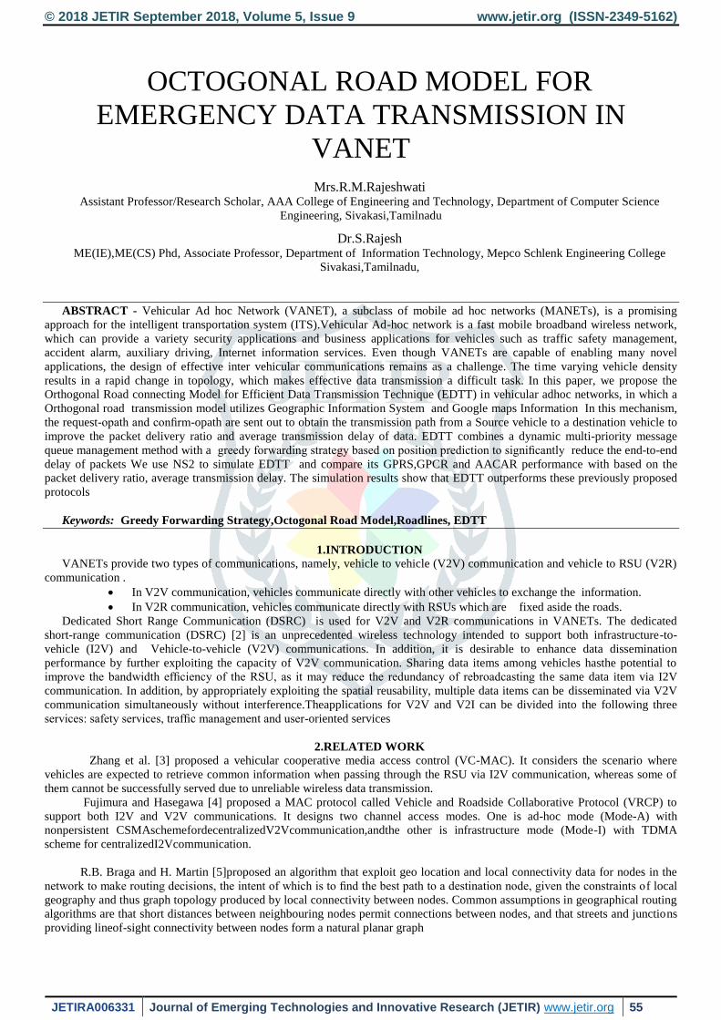
Fig 3a-First Layer Midpoint
Fig 3b-Each layer Midpoint
Since the θEAB is the minimum angle bigger than θD1AD2, B and E are chosen to be the first-layer midpoints in Fig. 2. After
finding the first-layer midpoints, the process will be repeated to find second-layer midpoints C, G, F. The process is repeated until
the destination midpoints are searched. Through this strategy, we can construct the octagonal road model, according to which the
available paths consisting of road midpoints can be found. The capital letters with the same color denote the midpoints of the
same layer in Fig. 3(b). The black solid lines are the road segments, which referring to the searching paths represent the boundary
road lines in this model. The dotted lines connecting the midpoint with same layer represent the interconnecting road lines which
restrict the searching area. So the available paths consist of midpoints are ABCHD1, ABGHD1, AEGD2, AEFD2.
4.4 Selecting the transmission path
Based on the available paths obtained in section A, the source vehicle sends out request-opath to the destination vehicle along
each path before the transmission of data packets. When the destination vehicle receives a request-opath, it returns a response-
opath to the source vehicle along the original path. The transmission delay of the path is calculated after the source vehicle
receiving the response-opath. Besides, the source vehicle start a timer when it sends out the request-opath. If the request timer
expires but there are no response-opath received, the source vehicle will restart to search the available paths, then it will send out
request-opath again. The path which has the shortest transmission delay is chosen as the transmission path for emergency
information
Table 1 shows the symbols used in algorithm path Discovery
Symbol Description
ID sv ID of Source Vehicle
ID dv ID of destination Vehicle
ID nv ID if neighboring Vehcile
Is Source Midpoint
Id Destination Midpoint
w Created octagonal model
t Created path tree
Ts Time Source ACAR send the request
Tr Time Source ACAR receive the response

© 2018 JETIR September 2018, Volume 5, Issue 9 www.jetir.org (ISSN-2349-5162)
JETIRA006331 Journal of Emerging Technologies and Innovative Research (JETIR) www.jetir.org 59
4.5 Algorithm for path Discovery
Procedure path_discover(ID sv,IDdv)
determine the Isv and Idv
create orthogonal road model w
create path tree t
get paths by DFS
send request-opath
activate (request_clock)
if receive response-opath when request clock is not timed out then
calculate packet delay(tr-ts)when receive response- opath
return the path with the smallest(Tr-Ts)
else
restart path discovery
end if
end if
end procedure
4.6 Greedy forwarding strategy
In this paper, we use a restricted greedy forwarding strategy based on location prediction to solve this problem. It predicts the
location of neighbor nodes by calculating their information in neighbor list before forwarding packets.Then the forwarding node
sends the data packet to the selected neighbor based on its predicted location. Each vehicle can determine whether it is an
midpoint node. When an midpoint node broadcasts Hello messages which includes its location information, it identifies itself as
an midpoint node in Hello messages. In this paper, vehicles are divided into midpoint nodes and ordinary nodes. Obstacles on the
sides of the roads can obstruct the transmission of wireless signals. As a result, it is difficult to directly forward data packets from
an ordinary node to another ordinary node in a different road segment, necessitating the help of an midpoint nodes to relay. In
addition, the other reason why we divide nodes is because ordinary nodes’ driving track is limited, but the movement of midpoint
node is uncertain. In summary, it is necessary to divide vehicles into ordinary nodes and midpoint nodes, so that we can use
different strategies to forward data packets. Vehicles in a highway environment can be assumed to be moving at a constant speed.
But in an urban environment, the complex road conditions will lead to frequent change of vehicles speeds. In order to keep the
calculation simple, we assume that the movement of vehicles is uniform acceleration linear motion in the Beacon period; this is
justified due to the short duration of the beacon. The predicted position of node is given by Eqs. (4) and (5).
x = x0 + v(t−t0)cosθ + 1/ 2α (t−t0)2 cosθ (4)
y = y0 + v(t−t0)sinθ + 1/ 2 α (t−t0)2 sinθ (5)
Set the rectangular coordinate system on the map, the origin of coordinates is the lower left corner of the map, the positive
direction of the vertical axis (+Y ) is north, and the positive direction of the horizontal axis (+X) is east. (x0,y0) denotes the
position of the vehicle, v and a denotes the speed and the acceleration of the vehicle at time t0. t0 is the time that current node
receives the Hello message. θ is the angle between the direction of movement and the positive direction of the x− axis. t is the
current time, (x,y) is the predicted position of the vehicle at time t.
Forwarding from an ordinary node In the road segment between two adjacent midpoints, the ordinary forwarding vehicle predicts the real-time position of its
neighbor vehicles before forwarding the data packet. If there is no available midpoint node in its neighbor list, the data packet is
forwarded to the ordinary node which is closest to the next midpoint. If there are midpoint nodes in the neighbor list of the
forwarding vehicle, it will check whether the current road segment and the subsequent road segment in the selected path can be
combined into a long straight segment. If so, the forwarding vehicle will send the data packet to the neighbor node closest to the
midpoint which is the farthest midpoint of this long straight segment. Otherwise, it will forward the data packet to the midpoint
node which is at the corner midpoint in the transmission path. If there is no available node, the forwarding vehicle will ACARry
the packet until it finds an available next hop
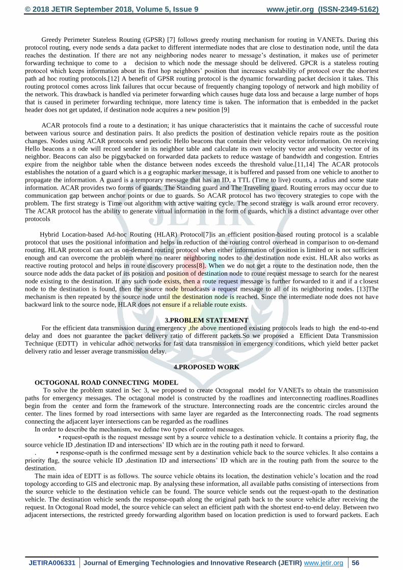
4.7 Forwarding from an midpoint node The information at the header of the packet will be checked to determine the next road segment in the transmission path. Then
the current midpoint node will forward the data packet to its neighbor which is closest to the next midpoint. Fig. 4 is a sketch to
illustrate these situations. In Fig 4(a), a is an ordinary node who wants to forward data, b, d and e are predicted real-time location
of the ordinary nodes. c is an midpoint node. Vehicle a forwards the data packet to the ordinary node b first. Then, if the next
midpoint marked in the packet header is B, node b will forward the data packet to the midpoint node c. Else if the next midpoint is
C, the data packet will be directly forwarded to the ordinary node e. This is because the current road segment and the next road
segment can be combined into a long straight segment and e is the closest node to the remote end of this long straight segment. In
Fig 4(b), a is the forwarding node, b, c, d and e are the real-time position predicted based on the information in the neighbor list of
a. If the next midpoint is C, a will forward the data packet to ordinary node c because node c is the closest node to midpoint C.

© 2018 JETIR September 2018, Volume 5, Issue 9 www.jetir.org (ISSN-2349-5162)
JETIRA006331 Journal of Emerging Technologies and Innovative Research (JETIR) www.jetir.org 60
4)a)Forwarding from Ordinary Node
4)b)Forwarding from Midpoint Node
4.8 Next hop Selection
The get current Midpoint and get next Midpoint functions are called to determine the current midpoint Ic(i.e., the last
midpoint the packet passed, initialized with the source midpoint) and the next midpoint In (initialized with the source midpoint
too) which is to be forwarded next The information of the transmission path is recorded in the packet header. Then, check
Midpoint function will judge whether the current vehicle is an midpoint node. If it is an midpoint node, the data packet will be
sent to the vehicle which is closest to In in its neighbor list . If the current node is an ordinary node, it will search the neighbor list
to find whether there are midpoint nodes or not. If there are midpoint nodes in its neighbor list and the next road segment to be
forwarded is located on the extension line of the current road segment, the data packet is sent directly to its neighbor node closest
to the farthest midpoint of this long straight segment If not, a neighbor node at the next midpoint is selected as the next hop
randomly, and the data packet is forwarded to it .If there is no midpoint node in its neighbor list, the forwarding vehicle will send
the data packet to the neighbor node closest to the midpoint In
Algorithm for Nexthop Selection
procedure get_nexthop(ID)
IC<- get current_Midpoint(ID,P)
In<-get next_Midpoint(P,Ic)
If check_midpoint(ID)=1 then
forward to its Nnv closet to In
else
if ID iv in IDnv then
if check_Segment(Ic,In,P)=1 then
forward to its Nnv closest to In
else
random forward to IDiv among its ID nv
end if
else
forward to its Nnv Closet to In
nd if
end if
end Procedure
V. DYNAMIC MULTI-PRIORITY SCHEDULING SCHEME FOR EMERGENCY PACKETS
In this paper, we divide data packets into three different priorities with Pq1, Pq2 and Pq3 according to the emergency levels of
the events creating the packets, Pq1 represents emergency packets with highest priority with minimum time delay requirements,
which are about public security and personnel life, such as traffic accidents causing casualties.. Next is Pq2, which are about
public safety, but the delay requirements are lower than Pq1. In order to analyze the timeless of different priority data packets, in
this paper we define the following variables: t is the end-to-end delay of the data packet forwarding from the
source vehicle to the destination vehicle, t(x,y) is the transmission delay for the data packet from vehicle x to vehicle y, t(x,y)
is the waiting time for the packet sending from x to y. Thus, the end-to-end delay t for the data packet forwarding from source
vehicle S to the destination vehicle D can be expressed as

© 2018 JETIR September 2018, Volume 5, Issue 9 www.jetir.org (ISSN-2349-5162)
JETIRA006331 Journal of Emerging Technologies and Innovative Research (JETIR) www.jetir.org 61
t = t(S,D) + t’(S,D) (6)
t includes following four aspects. (1) the time for each vehicle to receive the data packet, denoted as tr (2) the time for each
vehicle to process the data packet, denoted a tproc (3) the time for the each vehicle to push the data packet into the medium,
denoted as ds/ vt , where ds is the size of the packet and vt is the sending speed; (4) the transmission delay of the packet from the
source vehicle to the destination vehicle, denoted as d/ vp, in which 𝑑 = ∑ 𝑑𝑖𝑛𝑖−1 is the total length of the routing path from the
source vehicle to the destination vehicle and the vp is the speed of propagation. The relationship between t(S,D) and these
variables can be expressed by definition 1.
Definition 1: The transmission delay of packet from S to D.
t(S, D) = n ∗ (tr + tproc + ds/𝑉𝑡 ) + 𝑑/vp tr, vt, and tproc are equal when sending different priority data packets of the same size at the same vehicle. Therefore, if the
forwarding paths for different priority data packets sent from S to D are same, the values of t(S,D) are equal. Thus, the end-to-end
delay of different priority data packets is mainly affected by the waiting time t’(S,D). Assume that the packet needs to be forwarded
by n nodes during the transmission from S to D. N i,j is the number of packets in the queue with the priority j (j = 1, 2, 3) at node i.
k i,j represents the number of packets in queue with the priority whose deadlines are shorter than current packet. We define the
packet waiting time as follows.
Definition 2: The total waiting time of the packet with priority j transmitted from S to D is
𝑡^′ (𝑠, 𝑑) = ∑_(𝑖 − 1)^𝑛 =〖((𝑘_(𝑖, 𝑗) + 𝑁_(𝑖, 1 + ⋯ . +) 𝑁𝑖, 𝑗 − 1) ∗ (𝑡𝑟 + 𝑡𝑝𝑟𝑜𝑐 + 𝑑𝑠/𝑣𝑡)]
By the definition 2, the complete waiting time of the packets with the priority Pr1 is shown in Eq (9).
t1 ^′ = ∑_(𝑖 − 1)^𝑛 = ((𝑘_(𝑖, 1) ∗ (𝑡𝑟 + 𝑡𝑝𝑟𝑜𝑐 + 𝑑𝑠/𝑣𝑡))
The data packets with priority Pr2 need to wait for transmission of all packets with the priority Pr1 and the packets whose
deadlines are shorter than itself with priority Pr2. So, the total waiting time for it is shown in Eq (10)
t2’= ∑_(𝑖 − 1)^𝑛 = ((𝑘_(𝑖, 2) + 𝑁_(𝑖, 2 +) 𝑁𝑖, 1) ∗ (𝑡𝑟 + 𝑡𝑝𝑟𝑜𝑐 + 𝑑𝑠/𝑣𝑡)
Similarly, for the data packets with priority Pr3, the complete waiting time includes the waiting time of transmitting all
packets with priority Pr1 and Pr2, and the waiting timeof transmitting the packets whose deadlines are shorter than itself with
priority Pr3. It can be described as Eq (11).
t3’= ∑ ((𝑘𝑖,3 + 𝑁𝑖,2 +𝑁𝑖, 1) ∗ (𝑡𝑟 + 𝑡𝑝𝑟𝑜𝑐 +𝑑𝑠
𝑣𝑡)]
𝑛
𝑖−1
According to Eqs. (9) , (10) and (11), it is obvious that t1 is the shortest, and t2 is shorter than t3. Thus, the end-to-end delay
of the most emergency messages is the shortest. That proves our mechanism will deal the emergency messages first and it is
useful to reduce the end-to-end delay of emergency messages. When a vehicle receives data packets, the vehicle pushes the
packets into different priority queues based on the priority flag in the header of the data packets. The three priority queues share
the same buffer. When the buffer is full, data packets will be disACARded from the lowest priority queue to ensure that the
higher priority packets are not lost. Besides, the incoming packets with higher priority will be processed. However, the lower
priority packets which arrived earlier need to wait until all packets with highe rpriority have been processed. The packet whose
deadline is closest to current time in the current priority queue will be dequeued first.
Pq1
Pq2
Pq3
Table 2 Shows the terms used in algorithm of path Enque
Symbol Description
Pe The packet enqueued
Pd The Packet dequeued
to_drop The packet to drop
priority The priority of the packet
q_lim Limited length of Queue
q1 Pr1 queue
q2 Pr2 queue
q3 Pr3 queue
Buffer

© 2018 JETIR September 2018, Volume 5, Issue 9 www.jetir.org (ISSN-2349-5162)
JETIRA006331 Journal of Emerging Technologies and Innovative Research (JETIR) www.jetir.org 62
q1_l Length of q1
q2_l Length of q2
q3_l Length of q3
Td The deadline of the Packet
Tc Current Time
Algorithm Path Enque
Input:Pe
Procedure enque(Pe)
Up on receiving packets
If priority=1 then
q1->enque(Pe)
if( q1_l+q2_l+q3_l) q_lim then
to_drop<-last packet of q3
if to_drop=0 then
to_drop<-last packet of q2
if to_drop=0 then
to_dropPe
drop to_drop
else
drop to_drop
end if
else
drop to_drop
end if
end if
else if priority=2 then
q2 enque(Pe)
if( q1_l+q2_l+q3_l)>q_lim then
to_droplast packet of q3
if to_drop=0 then
if to_drop=0 then
drop Pe
else
drop to_drop
end if
end if
else if priority=3 then
q3enque(Pe)
if( q1_l+q2_l+q3_l)>q_lim then
drop Pe
end if
end if
end procedure
The above algorithm describes the process of the node inserting the packets into different priority queues. We use linked list to
implement the priority queues. If the packet priority is 1, the packet is pushed directly into queue Pq1 . If the buffer is overflow
after that, the tail packet in Pq3 queue is assigned to to drop If to drop is null, The packet at the tail of Pq2 queue is assigned to to
drop. If to drop is null too, the received packet Pe will be dropped.The procedure to put packets with priority 2 into Pq2 queue are
similar to the above process. Put the packet into Pq2 queue first And if the buffer is full, the tail packet in Pq3 queue is assigned to
to drop . To the packets with priority 3, if the queue is not full, the packet is pushed into Pq3 queue .Otherwise Pe will be dropped
Pq1 Priority=1
VI RESULT ANALYSIS
Average Transmission Delay (ATD): The performance of ATD of each protocol for all packets is evaluated with different
PGS . It can be seen that the ATD of four protocols increases when PGS increases. EDTT has the least ATD when compared to
the other three protocols because we select the routing path according to the least time delay resulting in significant reduction of
ATD. The below graph shows packet generation rate (X axis)Vs Average Transmission delay(Yaxis)

© 2018 JETIR September 2018, Volume 5, Issue 9 www.jetir.org (ISSN-2349-5162)
JETIRA006331 Journal of Emerging Technologies and Innovative Research (JETIR) www.jetir.org 63
Packet Delivery Ratio (PDR): PDR with different PGS of emergency packets Pq1 and all packets. Considering media access
conflicts and channel fading, especially taking into account the influence of obstacle on signal decay, packets may be sent out, but
may not be successfully received. Fig. 9 shows the correspondence between PDR of all data packets and PGS. The PDR of all
four protocols decreases as PGS increases. This is because when the PGS increases, the probability of packet loss increases due to
channel failure, buffer overflow, or expired packets. The overall performance of EDTT is best, both in low network load and high
network load. This is because the source vehicle sends request-opath and destination vehicle sends response-opath to confirm that
the path is available. Data packets are transmitted on reception of confirmed-spiders by the source vehicle. Besides, we predict the
location of the vehicles so that the link failures due to vehicle movement have been effectively reduced.The below graph depicts
packet generation rate (X axis)Vs Traffic Node Density(Yaxis)
VII CONCLUSION
To fulfil the real-time constraints of emergency data, we proposed EDTT, a novel orthogonal road connecting model provide
transmission mechanism for emergency data. We create a orthogonal model to restrict the searching area. Source vehicles send
out request opath and destination vehicles send respone-opath in this restricted area to establish efficient transmission paths.
EDTT can reduce the data transmission delay of emergency messages by using the dynamic multi-priority queue management
method to process packets. In this method, the high-priority emergency messages are processed first and the deadlines of the
packets are also considered. When forwarding data packets, we use restricted greedy forwarding strategy to choose the next hop.
REFERENCES
[1] Zheng Xu, Cai Zhipeng, Li Jianzhong, and Gao Hong. A study on Application-Aware Scheduling in Wireless Networks. IEEE
Transactions on Mobile Computing, 16(7):1787 – 1801, 2017.
[2] FCC, “Amendment of the Commission’s rules regarding dedicated short-range communication services in the 5.850–5.925
GHz band,” FCC report and order 06-110, July 20, 2016.
[3] J.Zhang,Q.Zhang,andW.Jia,“VC-MAC :A Cooperative MAC Protocol in Vehicular Networks”,
IEEETrans.Veh.Technol.,vol.58,no.3, pp. 1561–1571, Mar. 2009.
[4] K. Fujimura and T. Hasegawa, “A collaborative MAC protocol for inter-vehicle and road to vehicle communications,”in Proc.
7thIEEE ITSC, 2004, pp. 816–821.
[5]R. B. Braga and H. Martin, “Understanding Geographic Routing in Vehicular Ad Hoc Networks,” in GEOProcessing 2011 -
3rd International Conference on Advanced Geographic Information Systems, Applications, and Services, C.-P. R¨uckemann
and O. Wolfson, Eds. Gosier, Guadeloupe, France:
[6] Omprakash Kaiwartya and Sushil Kumar. Geocasting in vehicular adhoc networks using particle swarm optimization. In
Proceedings of the International Conference on Information Systems and Design of Communication, pages 62–66. ACM,
2014.
[7] Divya Gupta and Rajesh Kumar. An improved genetic based Routing Protocol for VANETs. In Confluence The Next
Generation Information Technology Summit (Confluence), 2014 5th International Conference-, pages 347–353. IEEE, 2014
[8] Naimah Yaakob, Ibrahim Khalil, Heshan Kumarage, Mohammed Atiquzzaman, and Zahir Tari. By-passing infected areas in
wireless sensor networks using BPR. IEEE transactions on computers, 64(6):1594– 1606, 2015.
[9] Qing Yang, Alvin Lim, Shuang Li, Jian Fang, and Prathima Agrawal. AACAR: Adaptive connectivity aware routing for
vehicular ad hoc networksincityscenarios. MobileNetworksandApplications,15(1):36–60, 2010

© 2018 JETIR September 2018, Volume 5, Issue 9 www.jetir.org (ISSN-2349-5162)
JETIRA006331 Journal of Emerging Technologies and Innovative Research (JETIR) www.jetir.org 64
[10]He Zhaobo, Cai Zhipeng, Yu Jiguo, Wang Xiaoming, Sun Yunchuan, and Li Yingshu. Cost-Efficient Strategies for
Restraining Rumor Spreading inMobileSocialNetworks. IEEE Transactions on Vehicular Technology, 66(3):2789 – 2800,
2017.
[11] Liu Xiulong, Li Keqiu, Min Geyong, Shen Yanming, Alex X. Liu, and Qu Wenyu. Completely Pinpointing the Missing
RFID Tags in a TimeEfficient Way. IEEE Transactions on Computers, 64(1):87 – 96, 2015
[12] Zhao, J.; Cao, G. (2006), "VADD: Vehicle-Assisted Data Delivery in Vehicular Ad Hoc Networks," INFOCOM 2006. 25th
IEEE International Conference on Computer Communications. Proceedings , vol., no., pp.1-12, April 2016.
[13] Leontiadis, I., Mascolo, C. (2007), “GeOpps:Geographical Opportunistic Routing for Vehicular Networks,” World of
Wireless, Mobile and Multimedia Networks, 2017.
[14] Karp, B. and Kung, H. T (2000), “GPSR: greedy perimeter stateless routing for wireless networks.” InMobile Computing
and Networking, pages 243-254, 2013.