Embed Size (px)
Citation preview
TM
Freescale Semiconductor Proprietary Information. Freescale™ and the Freescale logo are trademarksof Freescale Semiconductor, Inc. All other product or service names are the property of their respective owners. © Freescale Semiconductor, Inc. 2008.
Solutions for Electrical Traction Motor Drive
October 7, 2008
Roman FilkaSystems and Applications Engineer
FA101

TMFreescale Semiconductor Proprietary Information. Freescale™ and the Freescale logo are trademarksof Freescale Semiconductor, Inc. All other product or service names are the property of their respective owners. © Freescale Semiconductor, Inc. 2008. 2
Session Content
►Hybrid EV powertrain• Typical hybrid system• Driving hybrid – driving modes
►Freescale MCU solutions• Centralized (multi-axis) control• Distributed (single-axis) control
►Electric motor control• 3-phase motor control• Achieving Deterministic and Precise Control
►Freescale application solutions• Sensorless PM AC motor control
►Motor control on Freescale Web site

TMFreescale Semiconductor Proprietary Information. Freescale™ and the Freescale logo are trademarksof Freescale Semiconductor, Inc. All other product or service names are the property of their respective owners. © Freescale Semiconductor, Inc. 2008. 3
Please Ask Questions
► Do you have something in mind?
► Do I need to be more clear?
► Do not hesitate to interrupt.
► Do not hesitate to ask.
► This session is long!
► Ask when you have a question in mind.
?

TMFreescale Semiconductor Proprietary Information. Freescale™ and the Freescale logo are trademarksof Freescale Semiconductor, Inc. All other product or service names are the property of their respective owners. © Freescale Semiconductor, Inc. 2008. 4
Typical Hybrid System
• High efficiency gas engine• Planetary gear power split device
AC synchronous generator• High voltage AC-DC inverter• Nickel-metal hydride battery• Permanent magnet AC motor
Battery
Inverter
Motor
Drive wheels
Generator
Engine
Power split device
Power circuit

TMFreescale Semiconductor Proprietary Information. Freescale™ and the Freescale logo are trademarksof Freescale Semiconductor, Inc. All other product or service names are the property of their respective owners. © Freescale Semiconductor, Inc. 2008. 5
Typical Hybrid System
• High efficiency gas engine• Planetary gear power split
device AC synchronous generator
• High voltage AC-DC inverter• Nickel-metal hydride battery• Permanent magnet AC motor
Battery
Inverter
Motor
Drive Wheels
Generator
Engine
Reduction gear
Power split
device
Electric power
Drive power
Power circuit
TMFreescale Semiconductor Proprietary Information. Freescale™ and the Freescale logo are trademarksof Freescale Semiconductor, Inc. All other product or service names are the property of their respective owners. © Freescale Semiconductor, Inc. 2008. 6
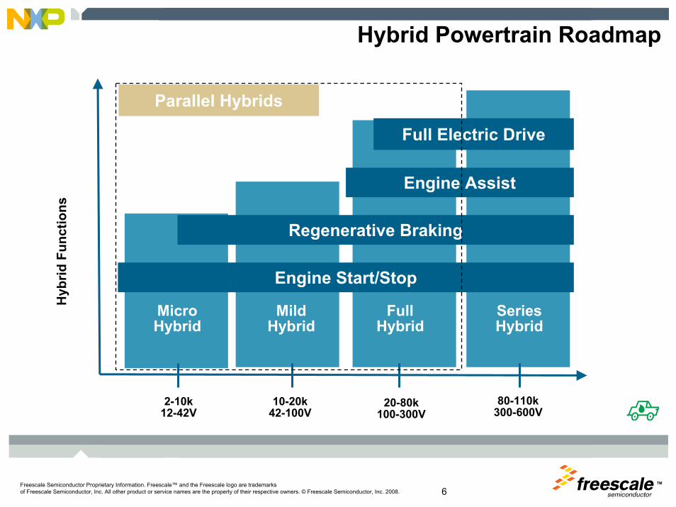
Hybrid Powertrain Roadmap
Engine Start/Stop
Regenerative Braking
Engine Assist
Full Electric Drive
MicroHybrid
MildHybrid
FullHybrid
SeriesHybrid
Hyb
rid F
unct
ions
2-10k12-42V
10-20k42-100V
20-80k100-300V
80-110k300-600V
Parallel Hybrids

TMFreescale Semiconductor Proprietary Information. Freescale™ and the Freescale logo are trademarksof Freescale Semiconductor, Inc. All other product or service names are the property of their respective owners. © Freescale Semiconductor, Inc. 2008. 7
Driving Hybrid
► Regenerative Braking. The electric motor applies resistance to the drivetrain causing the wheels to slow down. In return, the energy from the wheels turns the motor, which functions as a generator, converting energy normally wasted during coasting and braking into electricity, which is stored in a battery until needed by the electric motor.► Electric Motor Drive/Assist. The electric motor provides additional power to assist the engine in accelerating, passing, or hill climbing. This allows a smaller, more efficient engine to be used. In some vehicles, the motor alone provides power for low-speed driving conditions where internal combustion engines are least efficient.
Source: TOYOTA, Hybrid Synergy Drive, Information Portal
Hybrid strength

TMFreescale Semiconductor Proprietary Information. Freescale™ and the Freescale logo are trademarksof Freescale Semiconductor, Inc. All other product or service names are the property of their respective owners. © Freescale Semiconductor, Inc. 2008. 8
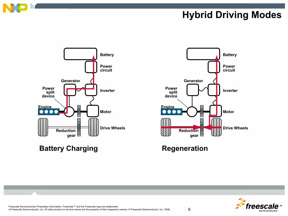
Hybrid Driving Modes
Battery
Inverter
Motor
Drive Wheels
Generator
Engine
Reduction gear
Power split
device
Power circuit
Low Speed Normal Driving
Battery
Inverter
Motor
Drive Wheels
Generator
Engine
Reduction gear
Power split
device
Power circuit
Battery
Inverter
Motor
Drive Wheels
Generator
Engine
Reduction gear
Power split
device
Power circuit
Sudden Acceleration
TMFreescale Semiconductor Proprietary Information. Freescale™ and the Freescale logo are trademarksof Freescale Semiconductor, Inc. All other product or service names are the property of their respective owners. © Freescale Semiconductor, Inc. 2008. 9
Hybrid Driving Modes
Battery
Inverter
Motor
Drive Wheels
Generator
Engine
Reduction gear
Power split
device
Power circuit
Battery
Inverter
Motor
Drive Wheels
Generator
Engine
Reduction gear
Power split
device
Power circuit
Battery Charging Regeneration
TMFreescale Semiconductor Proprietary Information. Freescale™ and the Freescale logo are trademarksof Freescale Semiconductor, Inc. All other product or service names are the property of their respective owners. © Freescale Semiconductor, Inc. 2008. 10
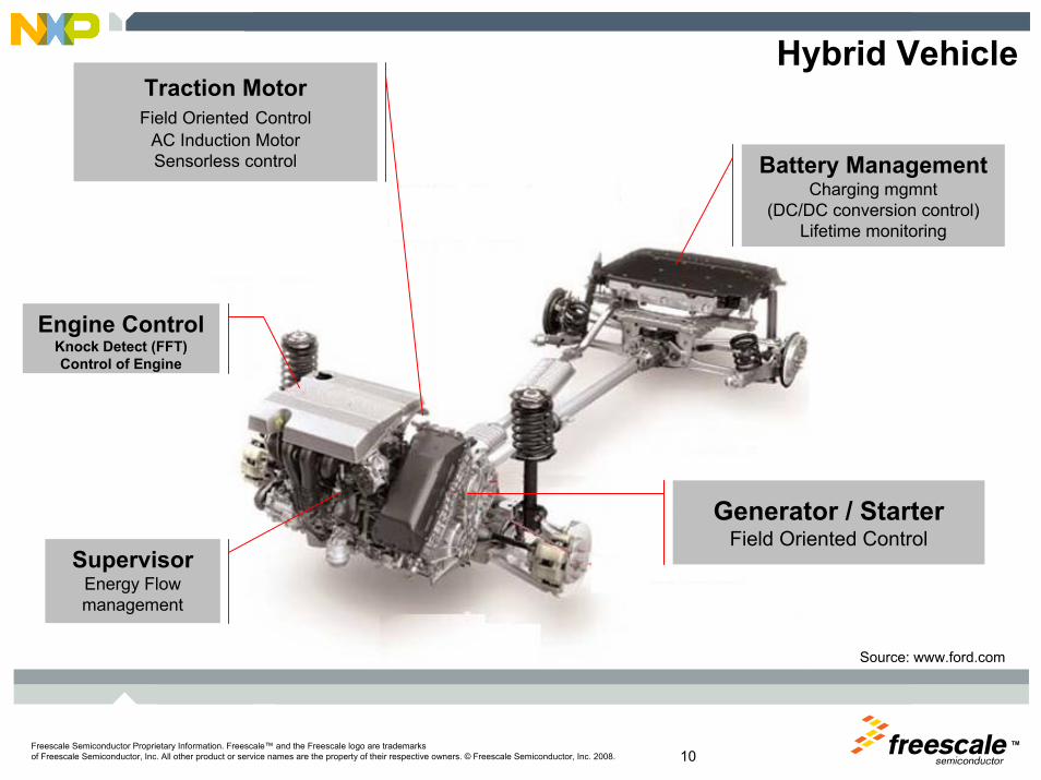
Hybrid Vehicle
Generator / StarterField Oriented Control
Battery ManagementCharging mgmnt
(DC/DC conversion control)Lifetime monitoring
Traction MotorField Oriented Control
AC Induction MotorSensorless control
Engine ControlKnock Detect (FFT)Control of Engine
SupervisorEnergy Flow management
Source: www.ford.com
TMFreescale Semiconductor Proprietary Information. Freescale™ and the Freescale logo are trademarksof Freescale Semiconductor, Inc. All other product or service names are the property of their respective owners. © Freescale Semiconductor, Inc. 2008. 11
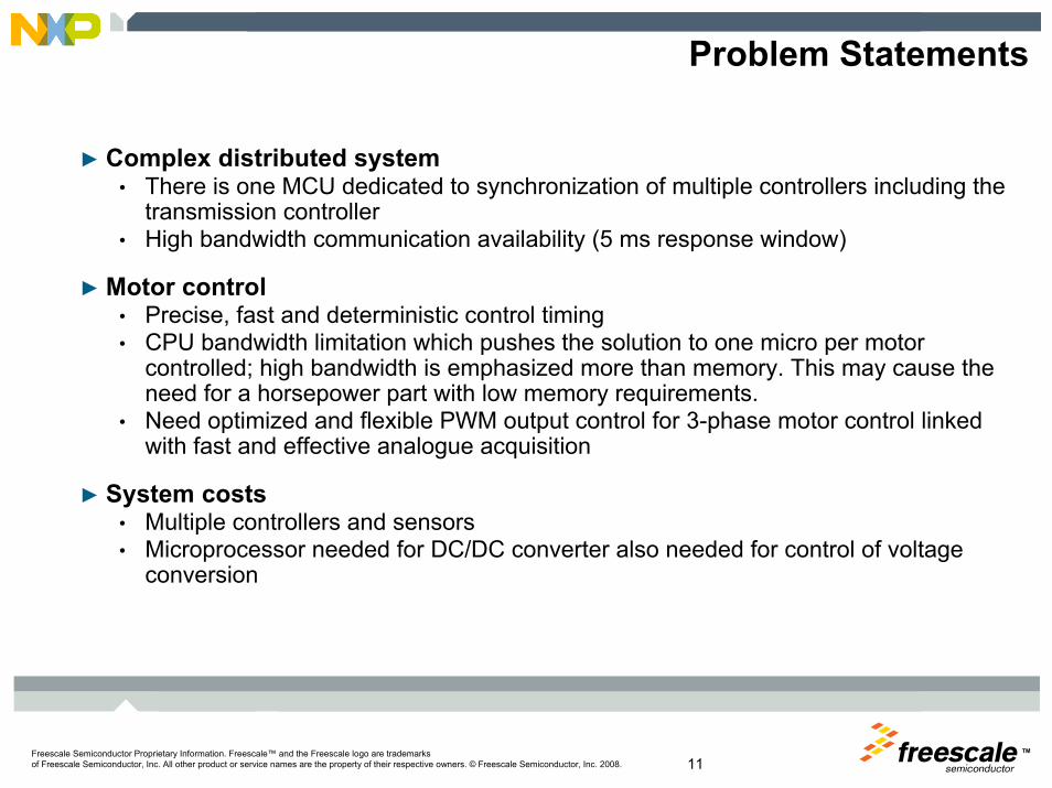
Problem Statements
► Complex distributed system• There is one MCU dedicated to synchronization of multiple controllers including the
transmission controller• High bandwidth communication availability (5 ms response window)
► Motor control• Precise, fast and deterministic control timing• CPU bandwidth limitation which pushes the solution to one micro per motor
controlled; high bandwidth is emphasized more than memory. This may cause the need for a horsepower part with low memory requirements.
• Need optimized and flexible PWM output control for 3-phase motor control linked with fast and effective analogue acquisition
► System costs• Multiple controllers and sensors• Microprocessor needed for DC/DC converter also needed for control of voltage
conversion

TM
Freescale Semiconductor Proprietary Information. Freescale™ and the Freescale logo are trademarksof Freescale Semiconductor, Inc. All other product or service names are the property of their respective owners. © Freescale Semiconductor, Inc. 2008.
Freescale MCU Solution
TMFreescale Semiconductor Proprietary Information. Freescale™ and the Freescale logo are trademarksof Freescale Semiconductor, Inc. All other product or service names are the property of their respective owners. © Freescale Semiconductor, Inc. 2008. 13
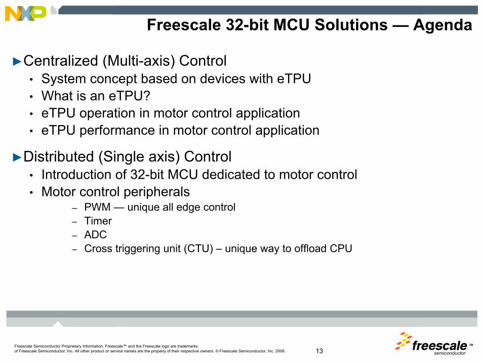
Freescale 32-bit MCU Solutions — Agenda
►Centralized (Multi-axis) Control• System concept based on devices with eTPU• What is an eTPU?• eTPU operation in motor control application• eTPU performance in motor control application
►Distributed (Single axis) Control• Introduction of 32-bit MCU dedicated to motor control• Motor control peripherals
– PWM — unique all edge control– Timer– ADC– Cross triggering unit (CTU) – unique way to offload CPU

TMFreescale Semiconductor Proprietary Information. Freescale™ and the Freescale logo are trademarksof Freescale Semiconductor, Inc. All other product or service names are the property of their respective owners. © Freescale Semiconductor, Inc. 2008. 14
Centralized Control
► Centralized control can be based on the powerful CPU supported by the motor control “co-processors”, called eTPU.
Battery
Generator
Engine
Power circuit
Motor
Inverter
ECU
MCU
MCU
eTPU
eTPU
CPU

TMFreescale Semiconductor Proprietary Information. Freescale™ and the Freescale logo are trademarksof Freescale Semiconductor, Inc. All other product or service names are the property of their respective owners. © Freescale Semiconductor, Inc. 2008. 15
The enhanced time processor unit is a programmable I/O controller with its own core and memory system, allowing it to perform complex timing and I/O management independently of the CPU. The eTPU is essentially a microcontroller all by itself! – motor control coprocessor
4
Timer ChannelsScheduler
Micro-engine
Execution Unit
Fetch and Decode
MDU
Host Interface
IPI
Code Memory (up to 64k)IPI
Debug Interface
Service request
Channel
Channel 0Channel 1Channel 2
Channel 31
Control
Control
Code
Data
System Configuration
Channel Control
Development and Test
Data Memory (up to 8k)
Debug
Control and data
TCR2 / Angle clock
What is an eTPU?
TCR1

TMFreescale Semiconductor Proprietary Information. Freescale™ and the Freescale logo are trademarksof Freescale Semiconductor, Inc. All other product or service names are the property of their respective owners. © Freescale Semiconductor, Inc. 2008. 16
Centralized Control—System Concept
► eTPU drives a motor independently of the CPU► eQADC (triggered by eTPU) samples analog quantities► eDMA transfers data between eQADC and eTPU► CPU only sets required quantity value (speed or torque)► CPU can handle higher level tasks
MotorDrive
enable/disablePWM signals
CPU HardwareDC-Bus
Us e
r In t
erfa
c e PWM Signals
DC-Bus Voltage
MotorPowerStage
eTPU
Sensor Signals
eQADCPhase Currents
eDMA
two parallel
conversions12-bit
Application State
Machine

TMFreescale Semiconductor Proprietary Information. Freescale™ and the Freescale logo are trademarksof Freescale Semiconductor, Inc. All other product or service names are the property of their respective owners. © Freescale Semiconductor, Inc. 2008. 17
eTPU Operation
► PWM signals generation► Shaft encoder signals processing► eQADC trigger signal generation
► PMSM/ACIMVC vector control loop► Speed-closed loop control► DC-bus break signal generation
QD
ASAC
SCrequiredspeed
requiredtorque
position difference& time difference
ADC Trigger
Shaft Encoder
DC-bus voltage
CPU eTPU Hardware
PMSMVC/ACIMVC PWMMAC
alphaduty-cycles
MotorInverter
PWMFbeta
phase_a_currentphase_b_currentphase_c_current
requiredtorque
actualspeed
QD_Index
position counter
BC DC-BusBreak
DC-bus voltagealpha
beta
DC
-Bus
Rip
ple
Elim
inat
ionu_alpha
u_beta
Inve
rse
Par
kTr
ansf
orm
u_q_lin
u_d_lin
Dec
oupl
ing
i_alpha
i_betaFlux
M
odel
sin
cos
i_q
u_q
u_d
i_d_required
i_d
Cla
rke
Tran
sfor
m
i_a
i_c
i_q_requiredPI
i_d
i_q
u_dc_busACIMVC
PI
i_b
omega_actual
DQ
Es
tabl
ishm
ent
i_alpha
i_beta
u_alpha
u_betapsi_r_alpha
psi_r_betacos
sin
omega_field
omega_field
Circ
leLi
mita
tion
TMFreescale Semiconductor Proprietary Information. Freescale™ and the Freescale logo are trademarksof Freescale Semiconductor, Inc. All other product or service names are the property of their respective owners. © Freescale Semiconductor, Inc. 2008. 18
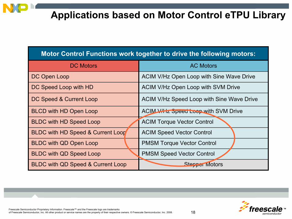
Applications based on Motor Control eTPU Library
AC MotorsDC Motors
Stepper MotorsBLDC with QD Speed & Current Loop
PMSM Speed Vector ControlBLDC with QD Speed Loop
PMSM Torque Vector ControlBLDC with QD Open Loop
ACIM Speed Vector ControlBLDC with HD Speed & Current Loop
ACIM Torque Vector ControlBLDC with HD Speed Loop
ACIM V/Hz Speed Loop with SVM DriveBLCD with HD Open Loop
ACIM V/Hz Speed Loop with Sine Wave DriveDC Speed & Current Loop
ACIM V/Hz Open Loop with SVM DriveDC Speed Loop with HD
ACIM V/Hz Open Loop with Sine Wave DriveDC Open Loop
Motor Control Functions work together to drive the following motors:

TMFreescale Semiconductor Proprietary Information. Freescale™ and the Freescale logo are trademarksof Freescale Semiconductor, Inc. All other product or service names are the property of their respective owners. © Freescale Semiconductor, Inc. 2008. 19
eTPU Performance
PMSM Vector Control ACIM Vector ControlMCF5235 (simplified) MPC5553/4 MPC5553/4
CPU/eTPU Clock 150 MHz/75 MHz 128 MHz 128 MHz
eTPU Engine Time Load
68.7% @ 10 RPM 45.6% @ 10 RPM 53.1% @ 10 RPMaverage
76.8% @ 1000 RPM 49.9% @ 1000 RPM 61.8% @ 1000 RPM
78.6% @ 10 RPM 50.3% @ 10 RPM 58.8% @ 10 RPMpeak
84.8% @ 10000 RPM 54.6% @ 1000 RPM 67.5% @ 1000 RPM
eTPU Memory Usage
Code RAM 6088 bytes 7508 bytes 8212 bytes
Data RAM 1024 bytes 1000 bytes 1072 bytes
Application ParametersPWM frequency: 20 kHz
Vector control update frequency: 20 kHz
Speed controller update frequency: 1 kHz
Shaft Encoder - increments per revolution: 4096

TMFreescale Semiconductor Proprietary Information. Freescale™ and the Freescale logo are trademarksof Freescale Semiconductor, Inc. All other product or service names are the property of their respective owners. © Freescale Semiconductor, Inc. 2008. 20
► eTPU Function Library and API
► eTPU Applications and Demonstrations
► eTPU Libraries Installation and Integration Guide
► eTPU Graphical Configuration Tool
► Links eTPU Compiler and Simulator Tools
► Link to eTPU VirtuaLab — Web interface to live demo
► Information on Trainings and Courses
► eTPU Documentation
eTPU Product Summary Web Pagehttp://www.freescale.com/etpu
Where Can I Learn More?

TMFreescale Semiconductor Proprietary Information. Freescale™ and the Freescale logo are trademarksof Freescale Semiconductor, Inc. All other product or service names are the property of their respective owners. © Freescale Semiconductor, Inc. 2008. 21
Distributed Control
► Distributed control is based on micro-controllers with dedicated motor control peripherals such as 6-ch. PWM, position sensor decoders, etc.
Battery
Generator
Engine
Power circuit
Motor
Inverter
ECU
MCU1
MCU2
FlexRayCAN
MCU
PWMCPUTimer
ADC
MCU1
TMFreescale Semiconductor Proprietary Information. Freescale™ and the Freescale logo are trademarksof Freescale Semiconductor, Inc. All other product or service names are the property of their respective owners. © Freescale Semiconductor, Inc. 2008. 22
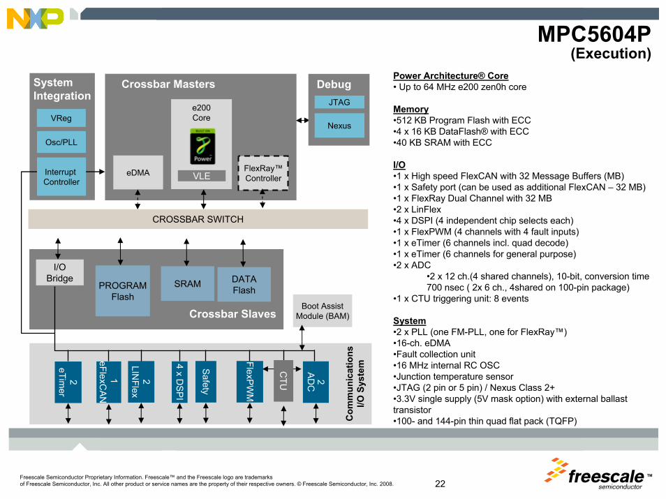
MPC5604P(Execution)
Power Architecture® Core• Up to 64 MHz e200 zen0h core
Memory•512 KB Program Flash with ECC•4 x 16 KB DataFlash® with ECC•40 KB SRAM with ECC
I/O•1 x High speed FlexCAN with 32 Message Buffers (MB)•1 x Safety port (can be used as additional FlexCAN – 32 MB)•1 x FlexRay Dual Channel with 32 MB•2 x LinFlex•4 x DSPI (4 independent chip selects each)•1 x FlexPWM (4 channels with 4 fault inputs)•1 x eTimer (6 channels incl. quad decode)•1 x eTimer (6 channels for general purpose)•2 x ADC
•2 x 12 ch.(4 shared channels), 10-bit, conversion time 700 nsec ( 2x 6 ch., 4shared on 100-pin package)
•1 x CTU triggering unit: 8 events
System•2 x PLL (one FM-PLL, one for FlexRay™) •16-ch. eDMA•Fault collection unit•16 MHz internal RC OSC•Junction temperature sensor•JTAG (2 pin or 5 pin) / Nexus Class 2+•3.3V single supply (5V mask option) with external ballast transistor•100- and 144-pin thin quad flat pack (TQFP)
I/OBridge SRAM
e200CoreVReg
Com
mun
icat
ions
I/O S
yste
m
Crossbar Slaves
Crossbar Masters
2A
DC
Nexus
JTAG
Debug
PROGRAMFlash
1 eFlexC
AN
eDMA VLE
Boot AssistModule (BAM)
Osc/PLL
CROSSBAR SWITCH
System Integration
FlexRay™Controller
FlexPW
M
DATAFlash
2LIN
Flex
2eTim
er
4 x DSPI
Safety
CTU
Interrupt Controller

TMFreescale Semiconductor Proprietary Information. Freescale™ and the Freescale logo are trademarksof Freescale Semiconductor, Inc. All other product or service names are the property of their respective owners. © Freescale Semiconductor, Inc. 2008. 23
Key Highlights► Feature set specifically addressing electric motor control applications
• Timer resolution and functions• PWM channel number and function • ADC
► Safety focus• Peripheral protection through access control• Core test capability• Flash and SRAM memories have error code correction ( ECC )• FlexRay™ networking
► Software ecosystem• Model based tools development• AUTOSAR• Optimized libraries for motor control and signal processing
► Zen 32-bit Power Architecture covers a complete range of performance and cost
• easy migration as requirements grow• Signal processing engine (on Z3 and above) for fast signal processing
► Proven eSys architecture used in most of the world’s powertrain control products
TMFreescale Semiconductor Proprietary Information. Freescale™ and the Freescale logo are trademarksof Freescale Semiconductor, Inc. All other product or service names are the property of their respective owners. © Freescale Semiconductor, Inc. 2008. 24
Boot Assist Module
NexusIEEE -ISTO
5001-2003Interrupt Controller
Crossbar Switch
I/OBridge SIU 512K
FLASH40K
SRAM
JTAGC -JTAGPowerPC™
e200z0
VLE
Vreg3.3 to 1.2VExt NPN
FMPL
4-40 MHz X -OSC
16 MHz RC-OSC
16 Ch.eDMA
FlexRay
4+1 Ch.PIT
Junctiontemp.Sensor
dSP
IdS
PI
eSC
I
FlexCA
N
Safety P.
dSP
I
PWM
Timer
Timer S&H S&H
Mux Mux
EEE
10bitI/F
10bitI/F eS
CI
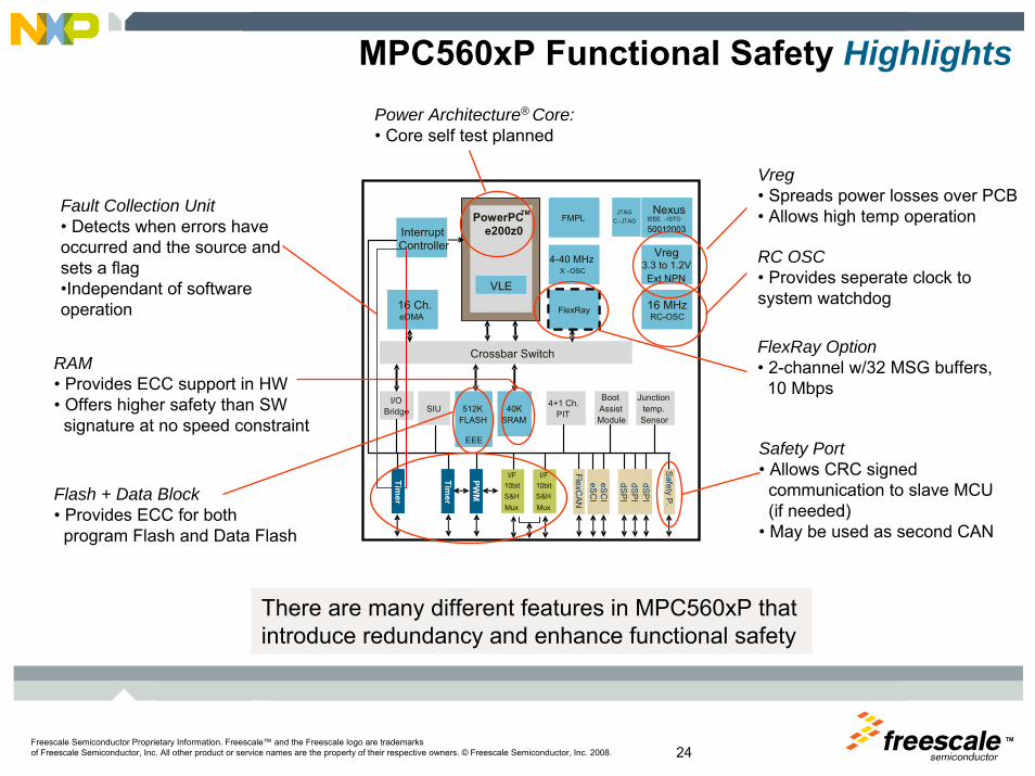
MPC560xP Functional Safety HighlightsPower Architecture® Core:• Core self test planned
Vreg• Spreads power losses over PCB• Allows high temp operation
RC OSC• Provides seperate clock to system watchdog
FlexRay Option• 2-channel w/32 MSG buffers,
10 Mbps
Safety Port• Allows CRC signed
communication to slave MCU (if needed)
• May be used as second CAN
RAM• Provides ECC support in HW• Offers higher safety than SW
signature at no speed constraint
Flash + Data Block• Provides ECC for both
program Flash and Data Flash
Fault Collection Unit• Detects when errors have occurred and the source and sets a flag•Independant of software operation
There are many different features in MPC560xP that introduce redundancy and enhance functional safety

TMFreescale Semiconductor Proprietary Information. Freescale™ and the Freescale logo are trademarksof Freescale Semiconductor, Inc. All other product or service names are the property of their respective owners. © Freescale Semiconductor, Inc. 2008. 25
MC Peripherals System Diagram
MCU
CTU
eTimer(Pos Counter)
PWM Reload
Timer/ Pos. decoder compare
External Signal
External Trigger
Trig
ger G
ener
ator
eTimer
flexPWM
Sch
edul
er
ADC Cmd
ADC Trig & Ackw
RealPWMs
PWMs
PWM Triggers
Real PWMs ADC Inputs
AD
C1
SHA
RED
AD
C2

TMFreescale Semiconductor Proprietary Information. Freescale™ and the Freescale logo are trademarksof Freescale Semiconductor, Inc. All other product or service names are the property of their respective owners. © Freescale Semiconductor, Inc. 2008. 26
Timer Module:• DSC based• Six Ch IC/OC• Double buffered registers for
detecting two edges in a row• eDMA supported• Integrated quad decoder support• 2 x BUS frequency high resolution
MCU
CTU
eTimer(Pos Counter)
PWM Reload
Timer/ Pos. decoder compare
External Signal
External Trigger
Trig
ger G
ener
ator
eTimer
flexPWM
Sch
edul
er
ADC Cmd
ADC Trig & Ackw
RealPWM’s
PWM’s
PWM Triggers
Real PWM’sADC Inputs
AD
C 1
SHAR
ED
AD
C 2
2x ADC• Up to 24channels, with 4 shared. • 10-bit• 700 nsec conversion time• Limit checking & zero crossing detect
Electric Motor Control Peripherals
FlexPWM• Based on DSC PWM• Optimized for 3ph motor control• One „extra“ pair of PWM integrated• Includes dead time insertion, fault channels,
center/edge alignment, Distortion correction, …
• Register protections• Double buffered registers• eDMA supported• 2 x BUS frequency high resolution
Cross Triggering Unit• Allows mcTIM, PWM, ATD
to be synchronized• Automatic ADC & eTimer acquisitions • No CPU intervention during the control
cycle
PWM0 Ch0PWM0 Ch1
PWM1 Ch0PWM1 Ch1
PWM2 Ch0PWM2 Ch1
PWM3 Ch0PWM3 Ch1
Con
trol
M
M
DC/DC
8
2
6
11 4 11
10bit
S&HMUX
I/F10bit
S&HMUX
I/F
11
TMFreescale Semiconductor Proprietary Information. Freescale™ and the Freescale logo are trademarksof Freescale Semiconductor, Inc. All other product or service names are the property of their respective owners. © Freescale Semiconductor, Inc. 2008. 27
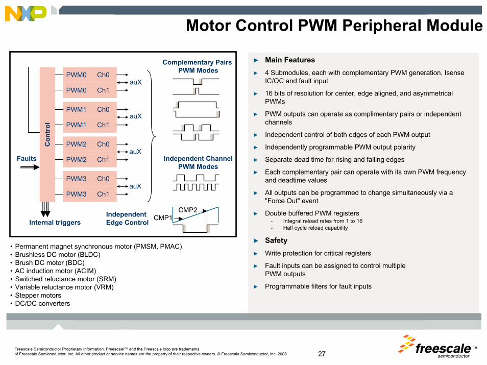
Motor Control PWM Peripheral Module
► Main Features► 4 Submodules, each with complementary PWM generation, Isense
IC/OC and fault input
► 16 bits of resolution for center, edge aligned, and asymmetricalPWMs
► PWM outputs can operate as complimentary pairs or independent channels
► Independent control of both edges of each PWM output
► Independently programmable PWM output polarity
► Separate dead time for rising and falling edges
► Each complementary pair can operate with its own PWM frequency and deadtime values
► All outputs can be programmed to change simultaneously via a "Force Out" event
► Double buffered PWM registers• Integral reload rates from 1 to 16• Half cycle reload capability
► Safety► Write protection for critical registers
► Fault inputs can be assigned to control multiple PWM outputs
► Programmable filters for fault inputs
PWM0 Ch0
Con
trol
PWM0 Ch1
PWM1 Ch0
PWM1 Ch1
PWM2 Ch0
PWM2 Ch1
PWM3 Ch0
PWM3 Ch1
Faults
Internal triggers
Complementary Pairs PWM Modes
Independent ChannelPWM Modes
auX
auX
auX
auX
• Permanent magnet synchronous motor (PMSM, PMAC) • Brushless DC motor (BLDC)• Brush DC motor (BDC)• AC induction motor (ACIM) • Switched reluctance motor (SRM) • Variable reluctance motor (VRM) • Stepper motors• DC/DC converters
CMP1CMP2Independent
Edge Control
TMFreescale Semiconductor Proprietary Information. Freescale™ and the Freescale logo are trademarksof Freescale Semiconductor, Inc. All other product or service names are the property of their respective owners. © Freescale Semiconductor, Inc. 2008. 28
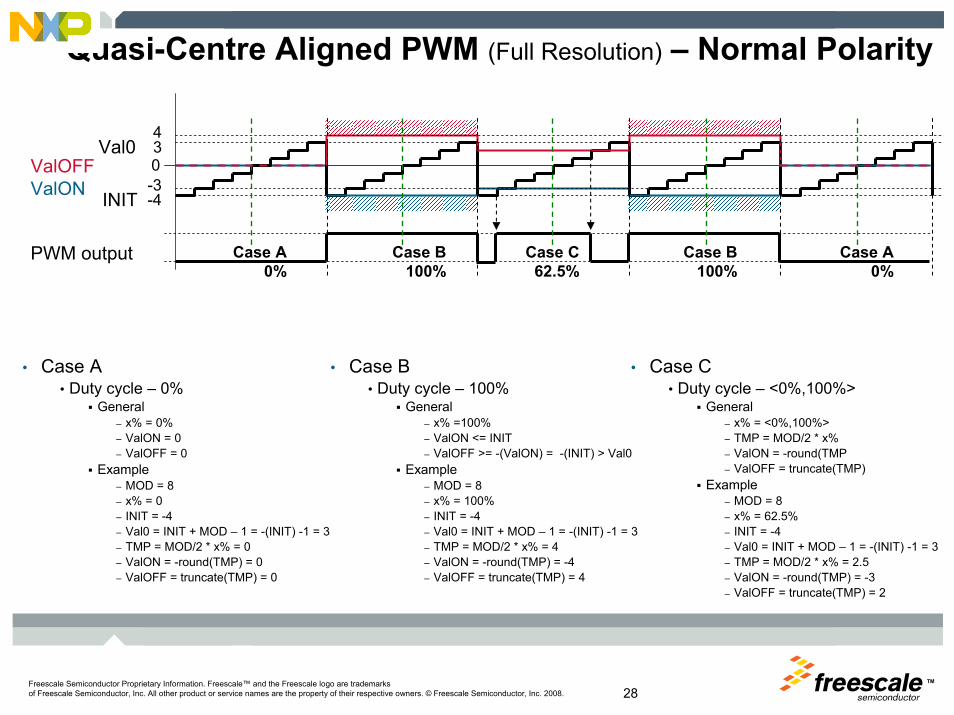
Quasi-Centre Aligned PWM (Full Resolution) – Normal Polarity
PWM output
0
-4
34
-3
Case A0%
Case B100%
Case A0%
Case B100%
Case C62.5%
ValONValOFF
INIT
Val0
• Case A• Duty cycle – 0%
General– x% = 0%– ValON = 0– ValOFF = 0
Example– MOD = 8– x% = 0– INIT = -4– Val0 = INIT + MOD – 1 = -(INIT) -1 = 3– TMP = MOD/2 * x% = 0– ValON = -round(TMP) = 0– ValOFF = truncate(TMP) = 0
• Case B• Duty cycle – 100%
General– x% =100%– ValON <= INIT– ValOFF >= -(ValON) = -(INIT) > Val0
Example– MOD = 8– x% = 100% – INIT = -4– Val0 = INIT + MOD – 1 = -(INIT) -1 = 3– TMP = MOD/2 * x% = 4– ValON = -round(TMP) = -4– ValOFF = truncate(TMP) = 4
• Case C• Duty cycle – <0%,100%>
General– x% = <0%,100%>– TMP = MOD/2 * x% – ValON = -round(TMP– ValOFF = truncate(TMP)
Example– MOD = 8– x% = 62.5% – INIT = -4– Val0 = INIT + MOD – 1 = -(INIT) -1 = 3– TMP = MOD/2 * x% = 2.5– ValON = -round(TMP) = -3– ValOFF = truncate(TMP) = 2

TMFreescale Semiconductor Proprietary Information. Freescale™ and the Freescale logo are trademarksof Freescale Semiconductor, Inc. All other product or service names are the property of their respective owners. © Freescale Semiconductor, Inc. 2008. 29
Other PWM Paterns — Example
►3-ph PWMs can be divided into:
• Standard – center aligned
• Two active vectors – left aligned
• Three active vectors – sequential
• Two active vectors – centered
• Three active vectors – center aligned (double switching)
60° - 120° 240° - 300°
120° - 180°60° - 120°
0° - 60° 60° - 120°
TMFreescale Semiconductor Proprietary Information. Freescale™ and the Freescale logo are trademarksof Freescale Semiconductor, Inc. All other product or service names are the property of their respective owners. © Freescale Semiconductor, Inc. 2008. 30
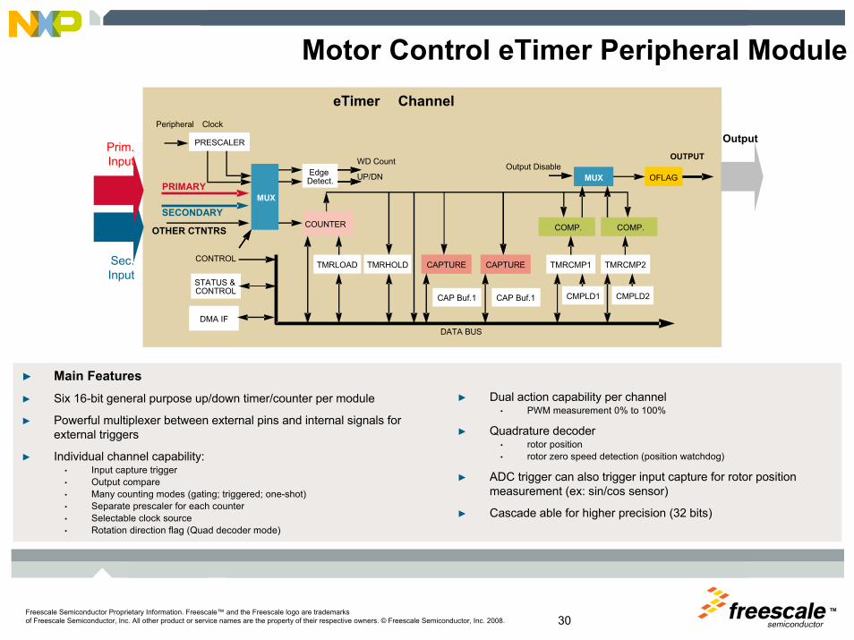
Motor Control eTimer Peripheral Module
► Main Features► Six 16-bit general purpose up/down timer/counter per module
► Powerful multiplexer between external pins and internal signals for external triggers
► Individual channel capability:• Input capture trigger• Output compare• Many counting modes (gating; triggered; one-shot)• Separate prescaler for each counter• Selectable clock source• Rotation direction flag (Quad decoder mode)
Sec.Input
PRIMARY
SECONDARY
PRESCALER
MUX
STATUS & CONTROL
DMA IF
COUNTER
TMRLOAD TMRHOLD
Edge Detect.
CAPTURE CAPTURE
CAP Buf.1 CAP Buf.1
TMRCMP1 TMRCMP2
CMPLD1 CMPLD2
COMP. COMP.
MUX OFLAG
OutputPrim.Input
CONTROL
OUTPUT
DATA BUS
Peripheral Clock
WD Count
UP/DNOutput Disable
OTHER CTNTRS
eTimer Channel
► Dual action capability per channel• PWM measurement 0% to 100%
► Quadrature decoder• rotor position• rotor zero speed detection (position watchdog)
► ADC trigger can also trigger input capture for rotor position measurement (ex: sin/cos sensor)
► Cascade able for higher precision (32 bits)
TMFreescale Semiconductor Proprietary Information. Freescale™ and the Freescale logo are trademarksof Freescale Semiconductor, Inc. All other product or service names are the property of their respective owners. © Freescale Semiconductor, Inc. 2008. 31
IC 1
IC1IC2
Counter
forward forwardjitter jitterbackward
PRESCALER 16-BIT
Trigger/ClockController
Input Capture
ARR16 bit counter
Encoder Interface
IC 2
output trigger
Output Compare
Encoder Index
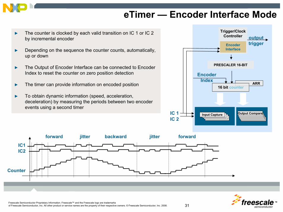
eTimer — Encoder Interface Mode
► The counter is clocked by each valid transition on IC 1 or IC 2 by incremental encoder
► Depending on the sequence the counter counts, automatically, up or down
► The Output of Encoder Interface can be connected to Encoder Index to reset the counter on zero position detection
► The timer can provide information on encoded position
► To obtain dynamic information (speed, acceleration, deceleration) by measuring the periods between two encoder events using a second timer

TMFreescale Semiconductor Proprietary Information. Freescale™ and the Freescale logo are trademarksof Freescale Semiconductor, Inc. All other product or service names are the property of their respective owners. © Freescale Semiconductor, Inc. 2008. 32
Encoder Interface Mode — Safety
► Position WATCHDOG Timer/Counter
► Two successive counts indicate proper operation and will reset the timer.
► The timeout value is programmable. When a timeout occurs, an interrupt to the processor can be generated.
► This timer is separate from the watchdog timer in the COP module.
PHASE A
PHASE B
+/-1
PositionCounter
Incr. Encoder
What happens when PHASE A is cut off ?
Normal Operation
Operation at phase cut off
Pos. WatchdogInt. Request
Watchdog timeout
ISR
+/-1 counts of the Position Counter do not reset the Watchdog timer!
The Watchdog can detect the encoder signal line cut off!

TMFreescale Semiconductor Proprietary Information. Freescale™ and the Freescale logo are trademarksof Freescale Semiconductor, Inc. All other product or service names are the property of their respective owners. © Freescale Semiconductor, Inc. 2008. 33
► Main Features
► 2 Independent units• <=12channels on ADC1, <=12 channels on ADC2, • 4 channels shared on ADC1 and ADC2
► 4 shared signals for motor control acquisitions• 3 for phase currents• 1 for other acquisitions
► 760 ns conversion time, including 125 ns sampling time
► 10-bit resolution (+/- 2LSB; target +/-1,5LSB)
► Single sample and hold per ADC• Dual sample through ADC cross triggering
► Separate sampling and conversionclock pre-scalers
Motor Control ADC Peripheral ModuleADC Unit
►ADC_INTERRUPTS
ADC data registers
►D15►D14►.►.►.
►D1►D0
SUCCESSIVE APPROXIMATION A/D CONVERTER
SAMPLESAMPLE
& &
HOLDHOLD
10 bit10 bit
ConvertorConvertor
AIN0
AIN1
AIN15
..
..
..
ANALOG MUX
►ADC_CONTROLTrigger Event for
conversion
Trigger event for injected conversion
END OF CONVERSION
END OF INJECTION
THRESHOLD VIOLATION
INTERRUPTS
Results FIFOs
►Analogwatchdog
SUCCESSIVE APPROXIMATION A/D CONVERTER
SAMPLESAMPLE
& &
HOLDHOLD
10 bit10 bit
ConvertorConvertor
AIN0
AIN1
AIN15
..
..
..
ANALOG MUX
10 4 10
12bit
S&HMUX
I/F12bit
S&HMUX
I/F
TMFreescale Semiconductor Proprietary Information. Freescale™ and the Freescale logo are trademarksof Freescale Semiconductor, Inc. All other product or service names are the property of their respective owners. © Freescale Semiconductor, Inc. 2008. 34
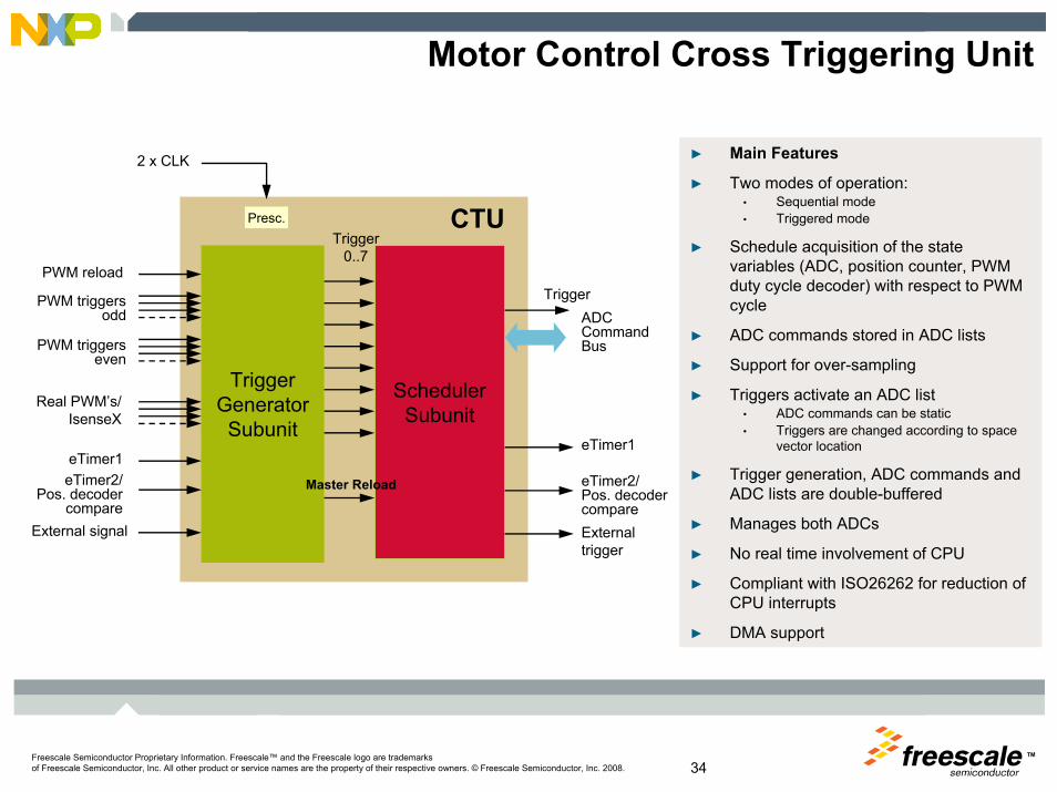
Motor Control Cross Triggering Unit
► Main Features
► Two modes of operation:• Sequential mode• Triggered mode
► Schedule acquisition of the state variables (ADC, position counter, PWM duty cycle decoder) with respect to PWM cycle
► ADC commands stored in ADC lists
► Support for over-sampling
► Triggers activate an ADC list• ADC commands can be static• Triggers are changed according to space
vector location
► Trigger generation, ADC commands and ADC lists are double-buffered
► Manages both ADCs
► No real time involvement of CPU
► Compliant with ISO26262 for reduction of CPU interrupts
► DMA support
CTU
Trigger GeneratorSubunit
eTimer1
External signal
SchedulerSubunit
PWM triggersodd
Real PWM’s/IsenseX
Trigger0..7
eTimer2/ Pos. decoder
compare
PWM reload
2 x CLK
ADC Command Bus
External trigger
Presc.
Master Reload
eTimer1
eTimer2/ Pos. decoder compare
PWM triggerseven
Trigger
TMFreescale Semiconductor Proprietary Information. Freescale™ and the Freescale logo are trademarksof Freescale Semiconductor, Inc. All other product or service names are the property of their respective owners. © Freescale Semiconductor, Inc. 2008. 35
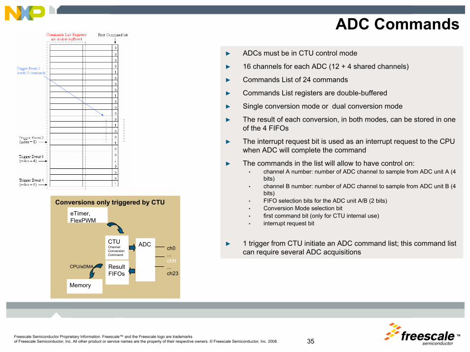
ADC Commands► ADCs must be in CTU control mode
► 16 channels for each ADC (12 + 4 shared channels)
► Commands List of 24 commands
► Commands List registers are double-buffered
► Single conversion mode or dual conversion mode
► The result of each conversion, in both modes, can be stored in one of the 4 FIFOs
► The interrupt request bit is used as an interrupt request to the CPU when ADC will complete the command
► The commands in the list will allow to have control on:• channel A number: number of ADC channel to sample from ADC unit A (4
bits)• channel B number: number of ADC channel to sample from ADC unit B (4
bits)• FIFO selection bits for the ADC unit A/B (2 bits)• Conversion Mode selection bit• first command bit (only for CTU internal use)• interrupt request bit
► 1 trigger from CTU initiate an ADC command list; this command list can require several ADC acquisitions
Conversions only triggered by CTU
ADCch0...chN...ch23
CTUChannel ConversionCommand
Result FIFOs
CPU/eDMA
Memory
eTimer,FlexPWM
TMFreescale Semiconductor Proprietary Information. Freescale™ and the Freescale logo are trademarksof Freescale Semiconductor, Inc. All other product or service names are the property of their respective owners. © Freescale Semiconductor, Inc. 2008. 36
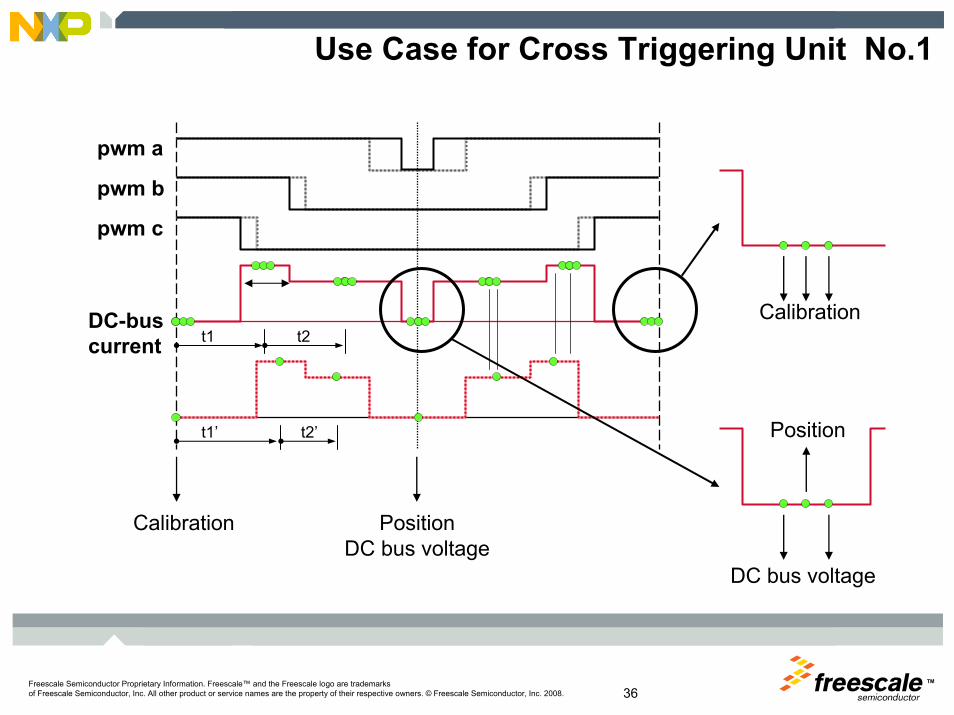
Use Case for Cross Triggering Unit No.1
t1 t2
t1’ t2’
pwm a
pwm b
pwm c
DC-bus current
PositionDC bus voltage
Calibration
Position
DC bus voltage
Calibration

TMFreescale Semiconductor Proprietary Information. Freescale™ and the Freescale logo are trademarksof Freescale Semiconductor, Inc. All other product or service names are the property of their respective owners. © Freescale Semiconductor, Inc. 2008. 37
Internal counter
Desired PWM
Use Case for Cross Triggering Unit No.2
Overall delay: ~0.4 ÷ 6 us
ADC trigger output event
ADC clock sync. ADC MUX selection S&H
ADC Sample
Trigger advancement to compensate ADC delays
ADC delays
Low pass filter delay + Topto: ~1usReal feedback signal
at ADC pin
TMFreescale Semiconductor Proprietary Information. Freescale™ and the Freescale logo are trademarksof Freescale Semiconductor, Inc. All other product or service names are the property of their respective owners. © Freescale Semiconductor, Inc. 2008. 38
Motor Control Peripheral
► Freescale motor control peripherals are well suited to handle various PWM patterns and ADC sampling schemes including very complex ones.
► Effective and versatile cycle-by-cycle control is possible while keeping SW driver load at minimum.
► Cross triggering unit (CTU) allows for two modes of operation (relative trigger timing to PWM cycle or to PWM edges); thus, you can select the most static mode with minimum CPU or SW load.
► In case of static pattern (e.g., PWM type, CTU trigger timing, ADC sampling scheme) whole operation is fully automatic with zero CPU or SW involvement.
TMFreescale Semiconductor Proprietary Information. Freescale™ and the Freescale logo are trademarksof Freescale Semiconductor, Inc. All other product or service names are the property of their respective owners. © Freescale Semiconductor, Inc. 2008. 39
In Summary►Power Architecture upward compatible roadmap
• Scalable performance Z0 to Z7►Reliable supply
• Dual source — Single architecture, separate manufacturing and distribution • Competitive sales and support
►Strong electric motor control• Timer resolution and functions• PWM channel number and function • ADC
►Next Geneneration safety approach• Core fault detection Lockstep and core self test• Peripheral protection through access control• Flash and SRAM memories have error code correction ( ECC )• FlexRay™ communications networking
►Software ecosystem• Model based tools development• AUTOSAR• Optimized libraries for motor control and signal processing
►Proven eSys Aachitecture used in most of the world’s powertraincontrol products
TM
Freescale Semiconductor Proprietary Information. Freescale™ and the Freescale logo are trademarksof Freescale Semiconductor, Inc. All other product or service names are the property of their respective owners. © Freescale Semiconductor, Inc. 2008.
AC Motor Control
TMFreescale Semiconductor Proprietary Information. Freescale™ and the Freescale logo are trademarksof Freescale Semiconductor, Inc. All other product or service names are the property of their respective owners. © Freescale Semiconductor, Inc. 2008. 41
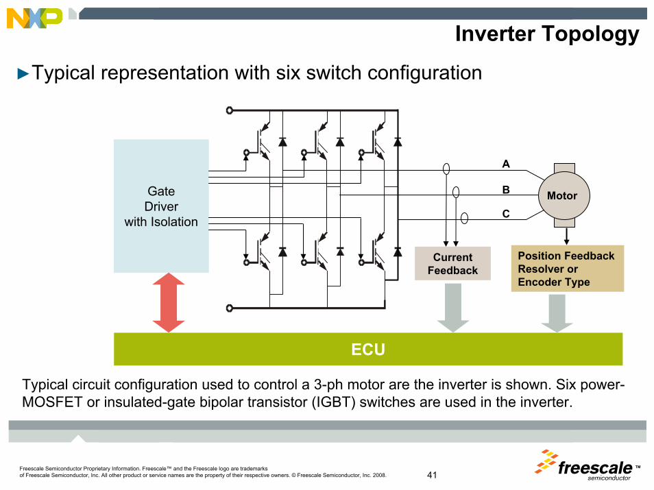
►Typical representation with six switch configuration
Inverter Topology
Typical circuit configuration used to control a 3-ph motor are the inverter is shown. Six power-MOSFET or insulated-gate bipolar transistor (IGBT) switches are used in the inverter.
Motor
A
B
C
Current Feedback
Position Feedback Resolver or Encoder Type
GateDriver
with Isolation
ECU

TMFreescale Semiconductor Proprietary Information. Freescale™ and the Freescale logo are trademarksof Freescale Semiconductor, Inc. All other product or service names are the property of their respective owners. © Freescale Semiconductor, Inc. 2008. 42
Fast and Precise Control — FOC
Outer Loop (slower) ~ 1Outer Loop (slower) ~ 1--5ms5ms
Inner Loop (faster) ~100Inner Loop (faster) ~100μμss

TMFreescale Semiconductor Proprietary Information. Freescale™ and the Freescale logo are trademarksof Freescale Semiconductor, Inc. All other product or service names are the property of their respective owners. © Freescale Semiconductor, Inc. 2008. 43
Torque Production Principle
► Electromagnetic torque production by the stator magnetic flux and magnet flux space vectors
γ
γsin⋅Ψ×Ψ⋅=Ψ×Ψ⋅= SRSRe ccT
°=→ 90)max( γeT
γγ

TMFreescale Semiconductor Proprietary Information. Freescale™ and the Freescale logo are trademarksof Freescale Semiconductor, Inc. All other product or service names are the property of their respective owners. © Freescale Semiconductor, Inc. 2008. 44
DC Motor Principle
► The stator of a permanent magnet DC motor is composed of two or more permanent magnet pole pieces.
► The rotor is composed of windings connected to a mechanical commutator, which mechanically ensures the angle between wire current and magnetic field ~ 90°.
SN
current
rotation
current
commutator
“Mechanical” FOC
mot
ion

TMFreescale Semiconductor Proprietary Information. Freescale™ and the Freescale logo are trademarksof Freescale Semiconductor, Inc. All other product or service names are the property of their respective owners. © Freescale Semiconductor, Inc. 2008. 45
Creation of Rotating Magnetic Field
► The space-vectors can be defined for all motor quantities.
0
π 2π
is
A
B
C
3-ph currents/MMF
A B C
oo 2401200 jC
jB
jAs eieieii ++=
1
-1
TMFreescale Semiconductor Proprietary Information. Freescale™ and the Freescale logo are trademarksof Freescale Semiconductor, Inc. All other product or service names are the property of their respective owners. © Freescale Semiconductor, Inc. 2008. 46
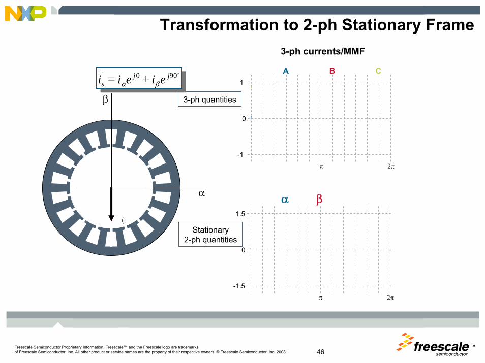
Transformation to 2-ph Stationary Frame
3-ph quantities
0
π 2π
β
α
0
π 2π
Stationary2-ph quantities
1
-1
1.5
-1.5
is
3-ph currents/MMF
A B C
α β
o900 jβ
jαs eieii +=

TMFreescale Semiconductor Proprietary Information. Freescale™ and the Freescale logo are trademarksof Freescale Semiconductor, Inc. All other product or service names are the property of their respective owners. © Freescale Semiconductor, Inc. 2008. 47
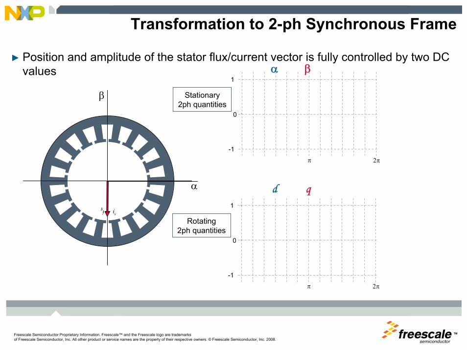
Transformation to 2-ph Synchronous Frame
► Position and amplitude of the stator flux/current vector is fully controlled by two DC values
is
α
β
0
π 2π
Stationary2-ph quantities
1
-1
0
π 2π
Rotating2-ph quantities
1
-1
id
iq
α β
d q
TMFreescale Semiconductor Proprietary Information. Freescale™ and the Freescale logo are trademarksof Freescale Semiconductor, Inc. All other product or service names are the property of their respective owners. © Freescale Semiconductor, Inc. 2008.
Transformation to 2-ph Synchronous Frame
► Position and amplitude of the stator flux/current vector is fully controlled by two DC values
is
α
β
0
π 2π
Stationary2ph quantities
1
-1
0
π 2π
Rotating2ph quantities
1
-1
iq
α β
d q

TMFreescale Semiconductor Proprietary Information. Freescale™ and the Freescale logo are trademarksof Freescale Semiconductor, Inc. All other product or service names are the property of their respective owners. © Freescale Semiconductor, Inc. 2008. 49
FOC Transformation Sequencing
Phase APhase BPhase C
α
β
Phase APhase BPhase C
d
q
d
q
α
β3-Phase
to2-Phase
Stationaryto
RotatingSVM
3-PhaseSystem
2-PhaseSystem
3-PhaseSystem
AC
Rotatingto
Stationary
ACDCC
ontr
olPr
oces
s
Stationary Reference Frame Stationary Reference FrameRotating Reference Frame
From measurementFrom measurement ??

TMFreescale Semiconductor Proprietary Information. Freescale™ and the Freescale logo are trademarksof Freescale Semiconductor, Inc. All other product or service names are the property of their respective owners. © Freescale Semiconductor, Inc. 2008. 50
► Sample the A/D on at least 2 of the phase currents simultaneously and read motor position.
► The A/D sample is performed on the same point during the PWM cycle (ex. midpoint of off time).
Deterministic Control
MotorControl(50 us)
PWMPeriod(50 us)
Current Ripple Profile
Max 0.5 us delay b/t successive A/D
sample 50us
Mid-Point of PWM Off Time
A/D Conversion of Motor Currents (~1us)
Motor Control (FOC) Time (~10us)
A/D Conversion always done at same point of
profile
Read Motor Position

TMFreescale Semiconductor Proprietary Information. Freescale™ and the Freescale logo are trademarksof Freescale Semiconductor, Inc. All other product or service names are the property of their respective owners. © Freescale Semiconductor, Inc. 2008. 51
A/D Converter-PWM Synchronization Benefits► ADC sampling helps to filtering the measured current – anti-aliasing► Noise free ADC sampling when the power switch is not acting► ADC sample is taken when shunt resistor signal (information) is available
PWM Period
PWM topPWM Bottom
Phase Current
Sampled and Average Currents
Shunt ResistorSignals
A/D
calc.
New PWM Parameters Calculation with Half-cycle Reload

TM
Freescale Semiconductor Proprietary Information. Freescale™ and the Freescale logo are trademarksof Freescale Semiconductor, Inc. All other product or service names are the property of their respective owners. © Freescale Semiconductor, Inc. 2008.
Freescale Application SolutionsSensorless PM AC Motor Control

TMFreescale Semiconductor Proprietary Information. Freescale™ and the Freescale logo are trademarksof Freescale Semiconductor, Inc. All other product or service names are the property of their respective owners. © Freescale Semiconductor, Inc. 2008. 53
Sensorless Control Basics
► What does it mean?• Controlling of electric motors without position/speed sensors• Utilizes motor phase voltage and current sensors• Uses models and algorithms to estimate the state variables (e.g.,
speed, mag. flux, resistance …)
M
Motorola
Dave’sControlCenter
Supply
Position/speedsensor
Ib
Ic

TMFreescale Semiconductor Proprietary Information. Freescale™ and the Freescale logo are trademarksof Freescale Semiconductor, Inc. All other product or service names are the property of their respective owners. © Freescale Semiconductor, Inc. 2008. 54
Electric Motor Type Classification
ELECTRIC MOTORS
AC DC
SYNCHRONOUSASYNCHRONOUS
BrushlessInduction Reluctance StepperSinusoidal
Permanent Magnet
Wound Field
Surface PM
Interior PM
• Stator same• Difference in rotor construction
If properly controlled• Provides constant torque• Low torque ripple
SR
VARIABLE RELUCTANCE

TMFreescale™ and the Freescale logo are trademarks of Freescale Semiconductor, Inc. All other product or service names are the property of their respective owners. © Freescale Semiconductor, Inc. 2007.
Sensorless Control of PM Motors
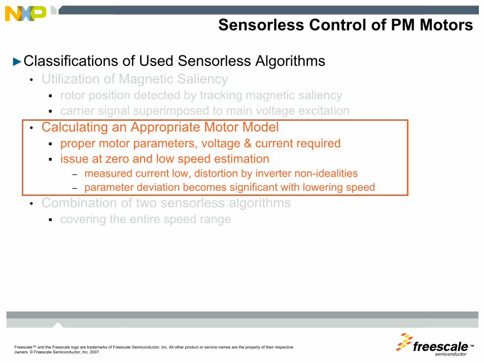
►Classifications of Used Sensorless Algorithms• Utilization of Magnetic Saliency
rotor position detected by tracking magnetic saliencycarrier signal superimposed to main voltage excitation
• Calculating an Appropriate Motor Modelproper motor parameters, voltage & current requiredissue at zero and low speed estimation
– measured current low, distortion by inverter non-idealities– parameter deviation becomes significant with lowering speed
• Combination of two sensorless algorithmscovering the entire speed range

TMFreescale™ and the Freescale logo are trademarks of Freescale Semiconductor, Inc. All other product or service names are the property of their respective owners. © Freescale Semiconductor, Inc. 2007.
IPMSM Saliency Identification
►HF Impedance Measurement• Verification of motor magnetic saliency at higher
frequencies under varying load conditions
• D-Q axis impedance difference gets smaller with increased load and might eventually be zero causing failure of sensorless algorithm
– This is caused by saturation of q-axis inductance with increased load.
►Armature Reaction Effect• Increasing load generates stronger armature
reaction
• The motor armature reaction shifts the resulting magnetic saliency towards the direction of q-axisSaliency shift due to
armature reactionSaliency shift due to armature reactionDecreased SaliencyDecreased Saliency
Salient Pole MotorSalient Pole Motor
50V @500Hz

TMFreescale™ and the Freescale logo are trademarks of Freescale Semiconductor, Inc. All other product or service names are the property of their respective owners. © Freescale Semiconductor, Inc. 2007.
Saliency Tracking Observer for Low Speeds
►Adding additional signal into rotating coordinates excites the motor at low and zero speed and makes the magnetic saliency signature visible.►Signal frequency chosen sufficiently high so no to interfere with base motor operating frequency. ► Signal amplitude chosen such that the hf currents generated by this signal are measurable with sufficient accuracy. ►If the two frames are misaligned, a high frequency signal injected in estimated d-axis will also be coupled into estimated q-axis and hf current response will be generated in estimated q-axis.
θactual
θerrd axis
q axis
d axis (est)
q axis (est)
( )errqdhf
mq ZZ
ZVi θω
2sin2
Δ−=
∧
PI regulator results in steady state error
value servoing to zero!
TMFreescale™ and the Freescale logo are trademarks of Freescale Semiconductor, Inc. All other product or service names are the property of their respective owners. © Freescale Semiconductor, Inc. 2007.
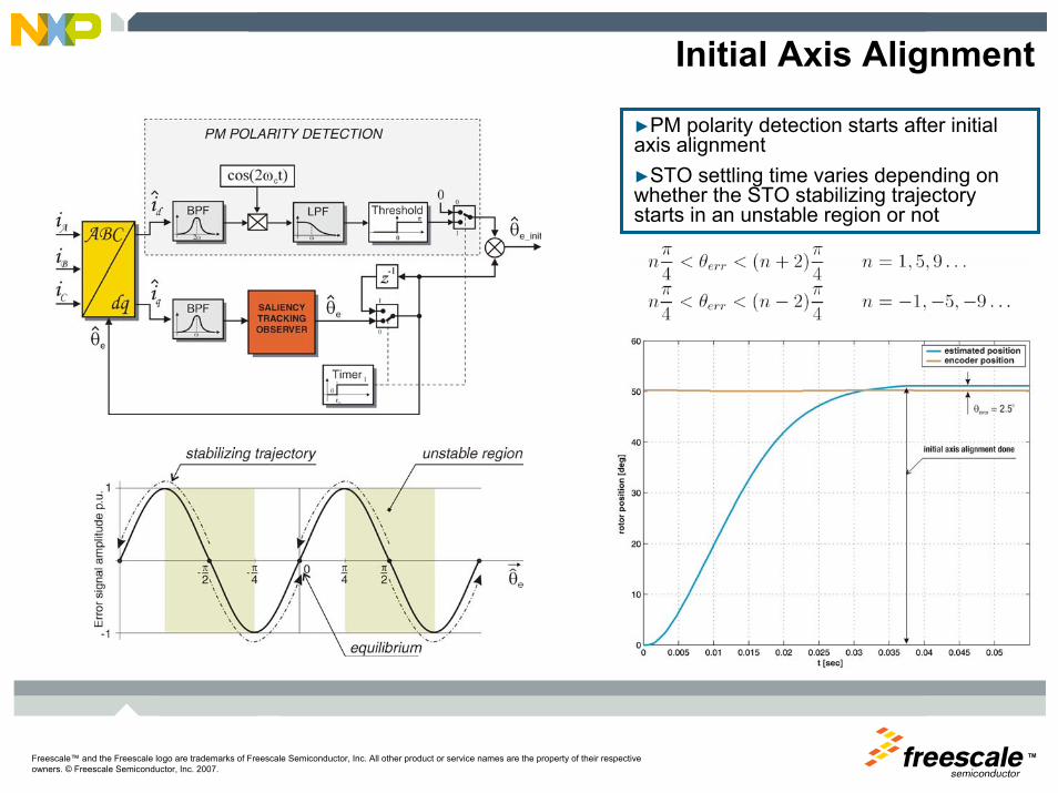
Initial Axis Alignment
►PM polarity detection starts after initial axis alignment►STO settling time varies depending on whether the STO stabilizing trajectory starts in an unstable region or not
TMFreescale™ and the Freescale logo are trademarks of Freescale Semiconductor, Inc. All other product or service names are the property of their respective owners. © Freescale Semiconductor, Inc. 2007.
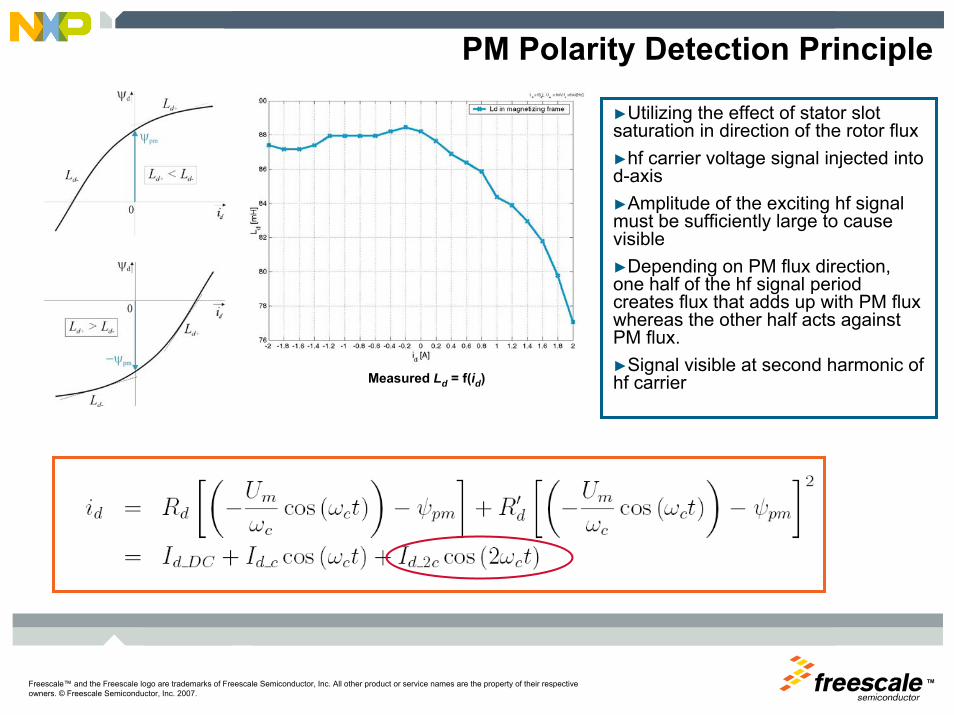
PM Polarity Detection Principle
►Utilizing the effect of stator slot saturation in direction of the rotor flux►hf carrier voltage signal injected into d-axis►Amplitude of the exciting hf signal must be sufficiently large to cause visible►Depending on PM flux direction, one half of the hf signal period creates flux that adds up with PM flux whereas the other half acts against PM flux.►Signal visible at second harmonic of hf carrierMeasured Ld = f(id)

TMFreescale™ and the Freescale logo are trademarks of Freescale Semiconductor, Inc. All other product or service names are the property of their respective owners. © Freescale Semiconductor, Inc. 2007.
PM Polarity Detection Experiments
with PM polarity detectionwithout PM polarity detection
TMFreescale™ and the Freescale logo are trademarks of Freescale Semiconductor, Inc. All other product or service names are the property of their respective owners. © Freescale Semiconductor, Inc. 2007.
Sensorless Control of PM Motors
►Classifications of Used Sensorless Algorithms• Utilization of Magnetic Saliency
rotor position detected by tracking magnetic saliencycarrier signal superimposed to main voltage excitation
• Calculating an Appropriate Motor Modelproper motor parameters, voltage & current requiredissue at zero and low speed estimation
– measured current low, distortion by inverter non-idealities– parameter deviation becomes significant with lowering speed
• Combination of two sensorless algorithmscovering the entire speed range
TMFreescale™ and the Freescale logo are trademarks of Freescale Semiconductor, Inc. All other product or service names are the property of their respective owners. © Freescale Semiconductor, Inc. 2007.
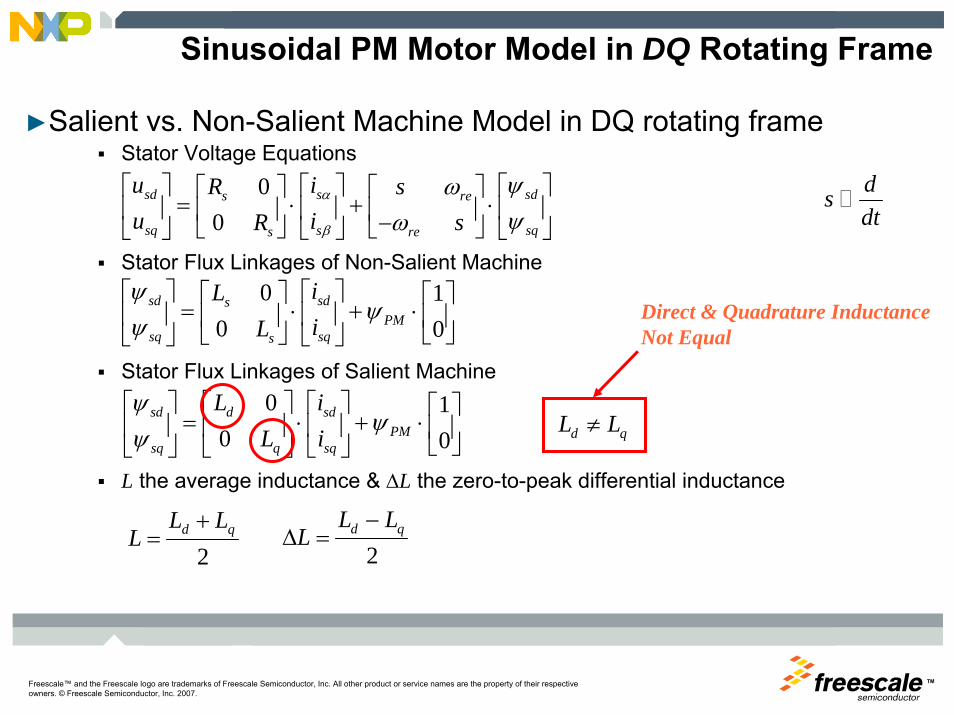
Sinusoidal PM Motor Model in DQ Rotating Frame
►Salient vs. Non-Salient Machine Model in DQ rotating frameStator Voltage Equations
Stator Flux Linkages of Non-Salient Machine
Stator Flux Linkages of Salient Machine
L the average inductance & ΔL the zero-to-peak differential inductance
dsdt
00
sd sdss re
sq sqss re
u iR su iR s
α
β
ψωψω
⎡ ⎤ ⎡ ⎤⎡ ⎤⎡ ⎤ ⎡ ⎤= ⋅ + ⋅⎢ ⎥ ⎢ ⎥⎢ ⎥⎢ ⎥ ⎢ ⎥−⎣ ⎦ ⎣ ⎦⎣ ⎦⎣ ⎦ ⎣ ⎦
0 10 0
sd sdsPM
sq sqs
iLiL
ψψ
ψ⎡ ⎤ ⎡ ⎤⎡ ⎤ ⎡ ⎤
= ⋅ + ⋅⎢ ⎥ ⎢ ⎥⎢ ⎥ ⎢ ⎥⎣ ⎦⎣ ⎦⎣ ⎦ ⎣ ⎦
0 10 0
sd d sdPM
sq q sq
L iL i
ψψ
ψ⎡ ⎤ ⎡ ⎤ ⎡ ⎤ ⎡ ⎤
= ⋅ + ⋅⎢ ⎥ ⎢ ⎥ ⎢ ⎥ ⎢ ⎥⎣ ⎦⎣ ⎦ ⎣ ⎦ ⎣ ⎦
2qd LL
L+
=2
d qL LL
−Δ =
d qL L≠
Direct & Quadrature InductanceNot Equal

TMFreescale™ and the Freescale logo are trademarks of Freescale Semiconductor, Inc. All other product or service names are the property of their respective owners. © Freescale Semiconductor, Inc. 2007.
Saliency Based Back-EMF Observer
► Saliency based back-EMF voltage is generated due to Ld≠Lq
► Because back-EMF term is not modeled, observer actually acts as a back-EMF state filter
► Observer is designed in synchronous reference frame, i.e. all observer quantities are DC in steady state making the observer accuracy independent of rotor speed.
voltagedtdcauses
dtdwithcombinedwhenwhich
ddcauses
ddL
=λθ
θλ
θ,,

TMFreescale™ and the Freescale logo are trademarks of Freescale Semiconductor, Inc. All other product or service names are the property of their respective owners. © Freescale Semiconductor, Inc. 2007.
Position Estimation Using Saliency Based Back-EMF
Position estimation steady state error at constant speed
Position estimation steady state error during speed ramp change

TMFreescale™ and the Freescale logo are trademarks of Freescale Semiconductor, Inc. All other product or service names are the property of their respective owners. © Freescale Semiconductor, Inc. 2007.
Sensorless Control of PM Motors
►Classifications of Used Sensorless Algorithms• Utilization of Magnetic Saliency
rotor position detected by tracking magnetic saliencycarrier signal superimposed to main voltage excitation
• Calculating an Appropriate Motor Modelproper motor parameters, voltage & current requiredissue at zero and low speed estimation
– measured current low, distortion by inverter non-idealities– parameter deviation becomes significant with lowering speed
• Combination of two sensorless algorithmscovering the entire speed range

TMFreescale™ and the Freescale logo are trademarks of Freescale Semiconductor, Inc. All other product or service names are the property of their respective owners. © Freescale Semiconductor, Inc. 2007.
Full Speed Sensorless Control Operation
Accurate at low speeds
Accurate at high speeds
► Full Operation Speed Range covered by two dedicated algorithms
► Crossover Merging Algorithm - based on FUZZY logic merges the two algorithm outputs into a single position/speed estimation.
► Sensorless Algorithms► Initial Position Detection
• avoids conventional alignment
► Low Speed Algorithm• Saliency Tracking Observer
► High Speed Algorithm• State Filter Observer
TMFreescale™ and the Freescale logo are trademarks of Freescale Semiconductor, Inc. All other product or service names are the property of their respective owners. © Freescale Semiconductor, Inc. 2007.
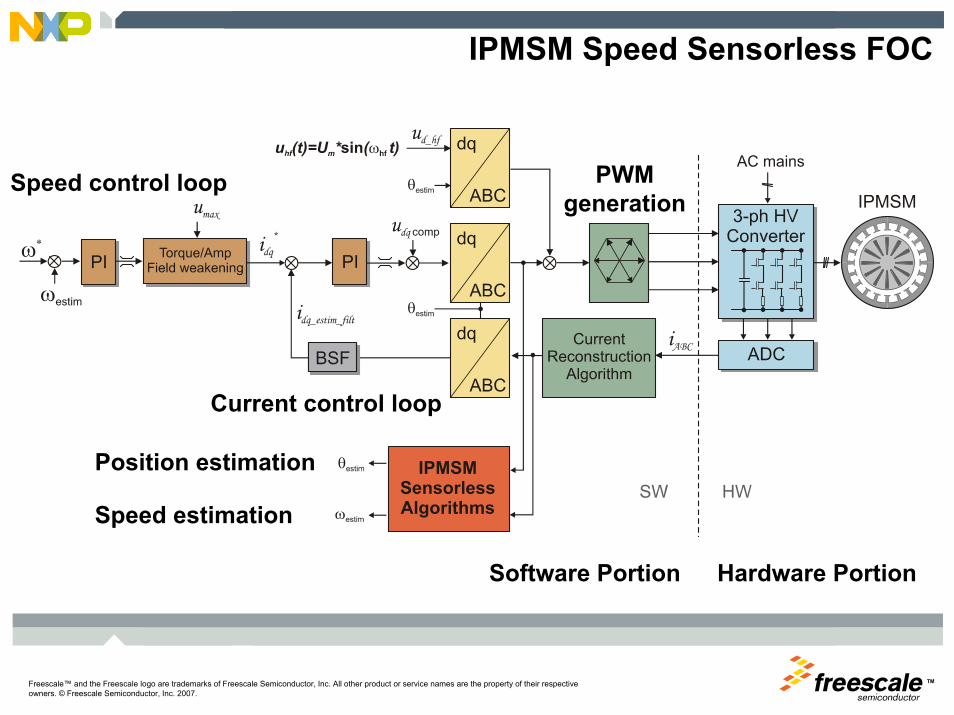
IPMSM Speed Sensorless FOC
Speed control loop
Speed estimation
PWMgeneration
Position estimation
Current control loop
Hardware PortionSoftware Portion
TMFreescale Semiconductor Proprietary Information. Freescale™ and the Freescale logo are trademarksof Freescale Semiconductor, Inc. All other product or service names are the property of their respective owners. © Freescale Semiconductor, Inc. 2008. 68
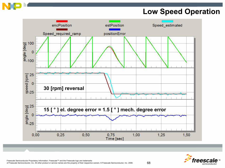
Low Speed Operation
30 [rpm] reversal
15 [ ° ] el. degree error = 1.5 [ ° ] mech. degree error
TMFreescale Semiconductor Proprietary Information. Freescale™ and the Freescale logo are trademarksof Freescale Semiconductor, Inc. All other product or service names are the property of their respective owners. © Freescale Semiconductor, Inc. 2008. 69
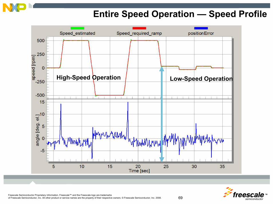
Entire Speed Operation — Speed Profile
High-Speed Operation Low-Speed Operation
TMFreescale Semiconductor Proprietary Information. Freescale™ and the Freescale logo are trademarksof Freescale Semiconductor, Inc. All other product or service names are the property of their respective owners. © Freescale Semiconductor, Inc. 2008.
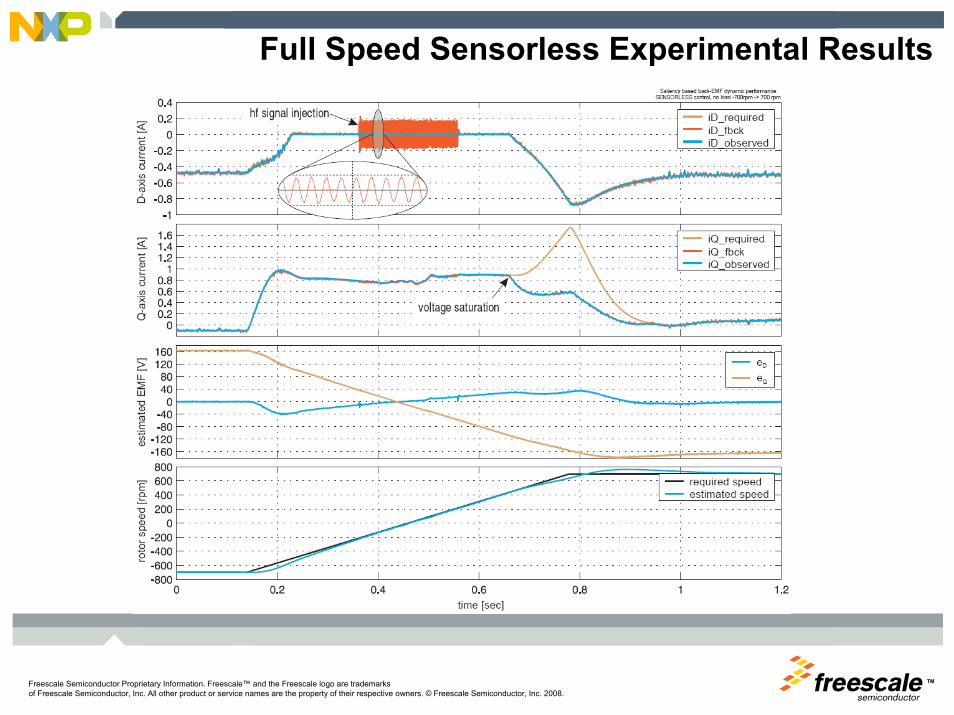
Full Speed Sensorless Experimental Results
TMFreescale Semiconductor Proprietary Information. Freescale™ and the Freescale logo are trademarksof Freescale Semiconductor, Inc. All other product or service names are the property of their respective owners. © Freescale Semiconductor, Inc. 2008. 71
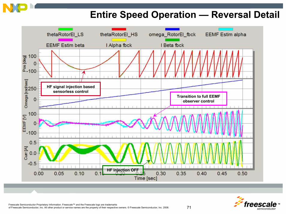
Entire Speed Operation — Reversal Detail
Transition to full EEMF observer control
HF injection OFF
HF signal injection based sensorless control

TM
Freescale™ and the Freescale logo are trademarks of Freescale Semiconductor, Inc. All other product or service names are the property of their respective owners. © Freescale Semiconductor, Inc. 2008.
Motor Control on Freescale Web siteReference designs, application notes, …
TMFreescale Semiconductor Proprietary Information. Freescale™ and the Freescale logo are trademarksof Freescale Semiconductor, Inc. All other product or service names are the property of their respective owners. © Freescale Semiconductor, Inc. 2008. 73
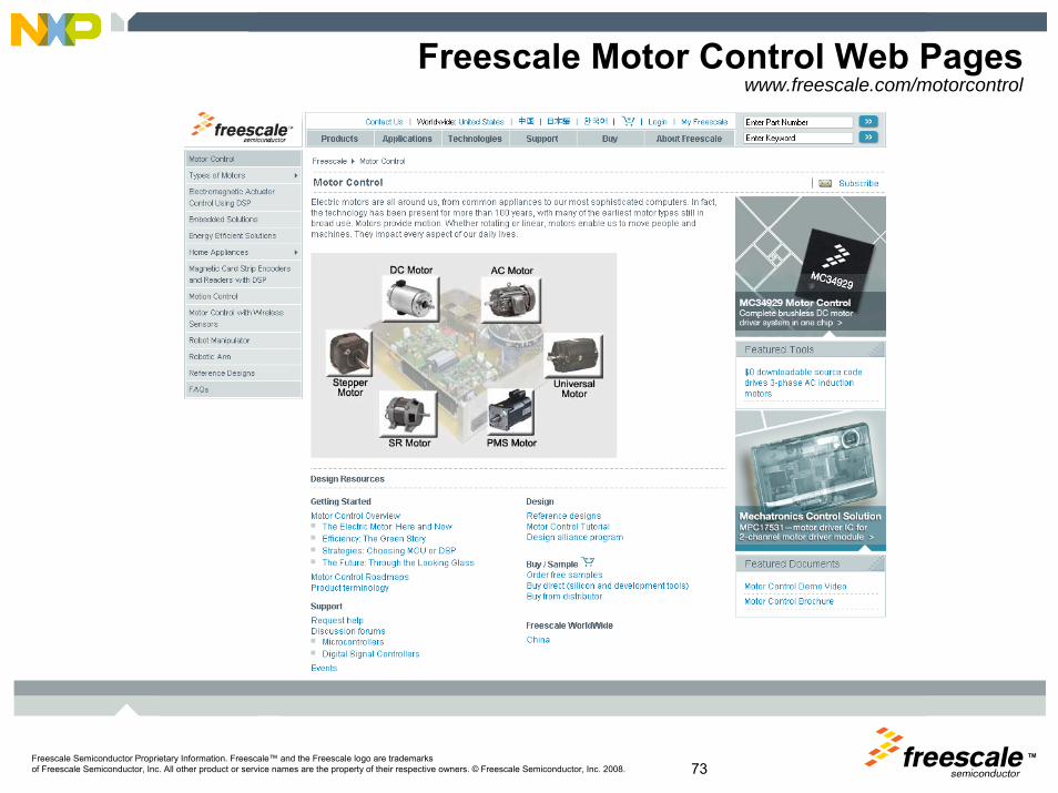
Freescale Motor Control Web Pageswww.freescale.com/motorcontrol

TMFreescale Semiconductor Proprietary Information. Freescale™ and the Freescale logo are trademarksof Freescale Semiconductor, Inc. All other product or service names are the property of their respective owners. © Freescale Semiconductor, Inc. 2008.
Session MaterialSession Location – Online Literature Libraryhttp://www.freescale.com/webapp/sps/site/homepage.jsp?nodeId=052577903644CB
DemosPedestal ID Demo Title

TM


![Driving Traffic + Conversions With Creativity [Case Study]](https://img.dokumen.tips/doc/110x75/55baa939bb61eb7a4f8b4671/driving-traffic-conversions-with-creativity-case-study.jpg)