Embed Size (px)
Citation preview

Ocean Wave Generator using Electromagnetic Induction
Sutton Smiley Adam McCuistion
Advisor: Dr. Prodanov

1
Table of Contents
Diagrams and Figures List 2 Acknowledgements 4 Abstract 5 General Introduction and Background 6 Project Requirements 10 Material Selection 12 Project Dimensions and Financial Breakdown 14 Test Plans 15 Test Results Part One 19 Development and Construction 26 Test Results Part Two 30 Test Results Part Three 36 Conclusion 40 Bibliography 41

2
Diagrams and Figures List Figures:
Figure 1: Demonstration of an Oscillating Water Column 7
Figure 2: Uppsala Point Absorber 8
Figure 3: Figure demonstrating how the testing coil will be performed 16
Figure 4: The different configurations of wire that will be tested. 16
Figure 5: Waveform of a single coil of wire with no breaks 19
Figure 6: Two coils 1cm apart 20
Figure 7: Two coils 5cm apart 20
Figure 8: Two coils placed 8.3cm apart 21
Figure 9: Two coils placed 20cm apart 21
Figure 10: Concept of a three wire design 22
Figure 11: Three wire design waveform output 23
Figure 12: Comparing waveforms induced by one and two magnets 24
Figure 13: Magnet Count versus Voltage 25
Figure 14: Mechanism for wiring pipe 27
Figure 15: Bushing and cork used to make pipe watertight 27
Figure 16: Bushing filed down 28
Figure 17: Data logger and circuitry inside acrylic pipe 28
Figure 18: Hole cut into outer piping 29
Figure 19: Ocean generator 29
Figure 20: Waveforms of the Phases A and B of Bermuda 31
Figure 21: Voltage Divider Circuit 32
Figure 22: Oscilloscope capture of a random waveform 33
Figure 23: Data logger output of a random waveform 33
Figure 24: Enlarged section of the oscilloscope output 34
Figure 25: Superimposed images of the data logger and oscilloscope 34
Figure 26: Data logger output, the oscilloscope image, and the fixed data logger output 35
Figure 27: Data logger values from best Ocean Trial 37
Figure 28: One wave passing through generator 38

3
Tables:
Table 1: Comparisons between the concept and OWC 7
Table 2: Comparisons between the concept and the point absorber 8
Table 3: List of Project Requirements 11
Table 4: Physical Measurements of one branch of the generator. 14
Table 5: Parts List and Price 14
Table 6: Preliminary testing to find best design 15
Table 7: Tests to be performed on the generator after construction 17,18
Table 8: Voltages versus number of magnets 25
Table 9: Values of resistance and length for all coils of wire 30
Table 10: Energies available over different time periods 37
Equations:
Equation 1: emf calculations 10
Equation 2: Calculation of length of wire 26
Equation 3: Voltage Divider Calculation 32
Equation 4: Finding Max Power 36
Equation 5: Inserting values to find Max Power 36
Equation 6: Nyquist Criterion calculation 38

4
I. Acknowledgements
Throughout the course of this project, several people have been instrumental to its completion.
We would like to thank Dr. Prodanov for his numerous contributions and guidance to the project
including its inception. We would like to thank the entire electrical engineering faculty and staff
for their support throughout our four years at Cal Poly. We would like to thank friends and
family for their support and belief of our abilities throughout not just our years at Cal Poly but
our whole lives. The completion of this project is a huge milestone in our lives and we’re
thankful to have shared it with people close to us.

5
II. Abstract
This project would introduce a design that allows energy to be harnessed from the motion of
waves and test to see if it is a feasible form of generation. The feasibility of the “generator” will
be determined on several factors including, but not limited to:
• Economic cost
• Power/Energy output
• The ability to scale linearly
• Environmental impact
The current concept is a triangle made of hollow tubes encompassing coils of wire and a magnet
that would move through the tube inducing current as it moves with the ocean. The triangle
design is used so at least two of the three magnets will always be inducing electricity no matter
the orientation of the device as the wave impacts it. The senior project would be to design and
build the generator and then to test how much energy is generated over an allotted time. The
results would be analyzed and presented with a recommendation regarding the future of the
design.

6
III General Introduction and Background
Since 1975, energy independence has been on the national spotlight. Over $172 billion
(adjusted for inflation in 2005 dollars) has been spent on achieving energy independence[1].
Senator Voinovich said, “It is critical that we grow more energy independent to increase our
competitiveness in the global marketplace and improve our national security. As less of our
energy needs are met with our resources, our nation is placed at the mercy of the oil-exporting
OPEC nations and vulnerable to geo-political instability and oil market volatility.”[2]
Our project aims to take steps towards becoming energy independent by introducing new
information concerning alternative energies. The problems we hope to address are: the growing
need for energy, the need for energy independence, the feasibility of energy harvesting from
waves, and the push towards renewable energy.
The solutions that currently exist are mainly solar and wind energy. The advantages that
wave energy have over solar is it can be harvested at all times of the day, not just during
sunlight. Water is denser than wind and waves and tides are more predictable than wind
patterns[3]. According to Roger Bedard, EPRI advocate, ocean energy potential will cost even
less than wind energy[3]. However, as it stands the development of wave and tidal energy is at an
early stage of researching and development[1]. This project aims to increase the level of
information available for others to expand upon.
There are several disadvantages regarding ocean energy. According the Brad Linscott,
author of Renewable Energy - A Common Sense Energy Plan, ocean tides aren’t feasible
because there must be a difference of at least 16 feet between the water level during high and low
tides. There exist around 40 locations in the world that meet this criterion. Comparatively, wave
energy usually requires the generation device to be located 130ft off the shoreline[1]; a task easily
accomplished on many shorelines. It’s difficult to imagine wave energy being the sole energy
source for America’s energy needs because the distance electricity would have to travel to reach
certain places on the continental U.S. However over half of Americans live on the coast and it
would be worth it to invest research[4].
According to Brad Linscott there are two proven methods of energy extraction from
waves: The oscillating Water Column (OWC) and the point absorber[1]. Looking at previous
attempts we can compare our design with those two methods.

7
The oscillating water column is a cylinder that is open at the top and closed at the bottom,
secured to the ocean floor by the bottom. A two-way air valve is located at the top of the cylinder
allowing air to flow. Air is compressed inside the cylinder and drives an air turbine. An in-depth
analysis was performed evaluating several aspects of oscillating column generation including:
cost, maintenance, infrastructure, generator performance and efficiency. An example is shown in
Figure 1.
Figure 29: Demonstration of an Oscillating Water Column[7]
From the analysis performed we are able to make the following comparisons in Table 1:
Area Oscillating Water Column Our Design
Maintenance X
Cost X
Generated Output X
Ability to connect to the grid X
Table 11: Comparisons between the concept and OWC
The article highlights how maintenance is a constant worry with the oscillating water
column, and since a large portion of the system is underwater and fastened to the ocean floor
making it more difficult of a system to maintain. Our design floats on the ocean surface meaning
maintenance is much easier. Comparing costs, our design is under 1000USD and using even the
best parts place our design hundreds of thousands of dollars cheaper than the OWC. The
generated output is much larger from the OWC because it uses professional grade generators and

8
the OWC used in the analysis is much larger than what we are planning on using. The OWC is
easier to connect to the grid because since it’s fastened to the ocean floor it can use the floor as a
method of transporting energy to the shore.
The point absorber contains a permanent magnet inside a long cylinder fastened to the
ocean floor. As the wave moves the cylinder bobs up and down like a buoy generating
electricity.
One wave generator that tested this design was the Uppsala Point Absorber[8]. Similar to
the OWC it requires impressive amounts of infrastructure in order to harvest energy. The
Uppsala Point Absorber is shown in Figure 2
Figure 30: Uppsala Point Absorber [8]
From the analysis performed we are able to make the following comparisons in Table 2:
Area Point Absorber Our Design
Maintenance X
Cost X
Generated Output depends depends
Ability to connect to the grid X
Table 12: Comparisons between the concept and the point absorber

9
Again we’re able to compare our design with the design completed by the Uppsala Point
Absorber project. The comparisons are almost identical with those made with the OWC, the only
difference being that the generated output of a single point absorber and with our design could be
comparable depending on the size of the magnets and the length of the cylinder used.
There are several different methods being employed and researched to generate power
from ocean waves. Devices have been being created since the early 90’s and innovated upon for
the last ~20 years. However, there are a few general designs that most devices seem to be based
upon. These are point absorber/buoy and surface following/attenuator. Our device borrows
elements from both. It would need to be loosely tethered to hold a general position like a point
absorber however no underwater components would be needed other than the anchor. It also
duplicates the idea of a surface following in that a side of the generator could be oriented parallel
to the direction of wave propagation in order for the magnet to slide up and down through the
coils. However, our triangle design hopes to produce power more efficiently by having three
sides to ensure that no matter the orientation of the device power is being generated by at least
two sides.

10
IV Project Requirements
The generator must be able to use the motion of waves to move magnets through coils of wire,
inducing a voltage. This will be done when the wave tilts the design and the magnets fall at an
angle. Listed below in Table 3 are the requirements of each item that will be used.
Although the intent of this project is to test and decide on the effectiveness of it being used as a
generator, there are certain electrical outputs desired. Since predicting wave amplitudes and
frequencies is impossible, specifications of the generator are calculated under ideal
circumstances. The ideal circumstance in this case is when a branch is fully vertical and a
magnet falls freely due to gravity. EMF is generated by a change of flux through turns of wires
given by the following equation:
𝑒𝑚𝑓 = −𝑁 ∆φ∆𝑡
Equation 1: emf calculations
This equation would mean that the strongest magnet should be selected because as it falls
through turns of wire it will yield the largest change of flux (∆φ). This equation also dictates that
the more turns of wire the larger induced voltage. However there are both financial and physical
limitations to our selections. Each branch should be able to output a measurable voltage under
“normal” ocean conditions and a sizable voltage under ideal conditions.

11
Component Description Requirements
Outer Shell The outer shell houses
everything inside; it is
in direct contact with
the water.
Buoyancy: The outer shell piping material needs to be
buoyant enough to support the weight of the wire,
magnets, and data measurement system.
Waterproof: The intent of the project is to place it in
the ocean while collecting data. The electronics inside
need to be free from water.
Durability: The material selected and the
fastening/joining agents need to be able to withstand
the elements and weather.
Inner Shell The inner shell has the
coils of wire wrapped
around it, and houses
the magnets inside.
Material properties: The material needs to be light,
so it doesn’t add unnecessary weight to the design. It
needs to be sturdy so that it won’t bend under the
weight of the added wire. It needs to have little
friction so the magnets are restricted in their
movements.
Wire Wired in coils so that
the magnets will induce
voltage through
movement.
Gauge: The gauge of the wire needs to be small
enough so that there will be enough turns to allow for
move voltage, yet large enough to handle currents
produced.
Data Logger Responsible for
measuring voltages and
storing it
Portability: Since experiments will be conducted
away from a laboratory setting the logger needs to be
able to store data without being tied to an outlet.
Size: Since the design looks to minimize size and
volume it must fit within the outer pipe.
Fittings
between
shells
Connects the outer
shells of three legs
Durability: It must be strong and waterproof to keep
the legs together while in the water.
Table 13: List of Project Requirements

12
V Material Selection
Piping material:
A major concern of this project is retaining buoyancy when the design is fully functioning. It will
include several thousand feet of wire, 9 relatively large magnets, electronic circuitry as well as
inner piping, and materials that will keep parts in place within the outer pipe. This will add to a
non-trivial weight that will not exceed the limits of the buoyancy of the material chosen.
With this project eventually being placed in water it is vital that it is waterproof to ensure that the
circuitry remains safe and functioning properly. The material chosen was acrylic tubing, which
is clear allowing us to visually inspect the project while the design is fully enclosed inside. Using
acrylic tubing with properly fitting joints should be able to safeguard the circuitry, as it is a
material that meets waterproof specifications. The material is extremely resistant to corrosion
and very durable which should suit our project well considering the exposure to the elements.
One requirement of this project is to make sure that it is environmentally friendly. This coincides
with the goal to make this device scalable (more devices could easily and efficiently be added to
the system to produce more power). PVC pipe was chosen as the inner piping material largely
because it is one of the world’s most sustainable products with an average lifespan of more than
110 years and requiring relatively small amounts of energy and resources to resource while
creating virtually no waste[5]. PVC pipe is very cheap and readily available at most hardware
stores and isn’t considered a high-risk item.
Magnets:
The magnet chosen was a rare earth magnet because it is the strongest magnet given the
operating conditions[6]. A grade N42 Neodymium magnet with nickel coating was selected for
use. The magnet was selected because of its dimensions and relative strength compared to its
price. Ideally the strongest magnet would be chosen however the budget of this project largely
dictated the magnet selection.
Wire:
The more turns correlates to a higher voltage, so the ability to produce more turns would be
desired. The way to meet this requirement is to use a wire with the smallest diameter possible so

13
that the wire could be wrapped as many times as possible around a pipe. The smallest wire
diameter (largest wire gauge) was selected that was readily available at large quantities.
Data Logger:
The data logger was selected largely on price and dimensions. Since price was the largest factor
we selected the cheapest data logger that met our dimensions and requirements. Therefore a
SparkFun Logomatic v2 data logger was selected that was able write to an 2GB SD card and was
able to write fast enough to store enough data points necessary for interpreting data.
Pipe Fittings:
Encasing the inner PVC pipes are acrylic tubes with a diameter of 2¾” and a length of 3 ft. At
either end there is a bushing with silicone pasted on and a cork is inserted to ensure that no water
can enter. For extra buoyancy and resilience another plastic pipe was added that houses both of
these inner pipes. This proved to be an effective way of keeping the device connected and safely
operating on top of the water.

14
VI Project Dimensions and Financial Breakdown
Project Dimensions:
Shown below in Table 4 are the physical measurements of one branch for the generator.
Excluded from Table 4 are some circuitry necessary for correct operation since their dimension
don’t have a significant impact on design considerations. The table discusses the parts length and
its diameter if applicable, if not the dimensions are noted. It is important to note that all of the
dimensions allow for more room than strictly necessary, allowing for margins of error in the
design.
Part Length Diameter Dimensions Outer tubing 5ft 4” N/A Exterior Pipe 3 ft 2 ¾” N/A Interior Pipe 2.5 ft ¾” N/A
Magnets 5/8” 1” N/A Data logger 4.06” N/A 4.06” x 0.66” x 1.00”
Wire (AWG 36) 9.4 miles 0.005” N/A
Table 14: Physical Measurements of one branch of the generator.
Finance and budget:
Shown in Table 5 is the price breakdown for this project. Listed under the “Part” heading is the
amount purchased for that item. In the case of the piping the amount purchased is noted in
length, otherwise it is just the amount.
Parts:
Part Price 10’ of 2.5” diameter acrylic pipe $80 10’ of 2” diameter PVC pipe $15 20’ of 4” diameter plastic tubing $7 3 4” diameter plastic tube fittings $6.50 6 PVC “caps” 2” diameter $7 9 N42 cylindrical magnets $75 9 miles of 36 AWG wire $100 Glue, foam, miscellaneous supplies $25 Logomatic v2 Data Logger $67 Total Cost $383
Table 15: Parts List and Price
15
VII Test Plans
The most critical part of the project will test during different stages of the project. Currently those three
stages are: Testing for the best design, which the tests are described in detail in Table 6. Then testing the
generator after it’s built, which the tests are described in Table 7. Then finally testing the generator in
the ocean, which the details are described below in this section.
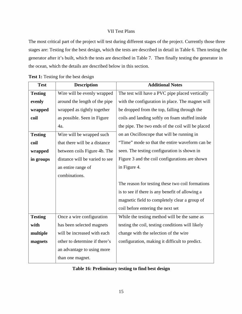
Test 1: Testing for the best design
Test Description Additional Notes
Testing
evenly
wrapped
coil
Wire will be evenly wrapped
around the length of the pipe
wrapped as tightly together
as possible. Seen in Figure
4a.
The test will have a PVC pipe placed vertically
with the configuration in place. The magnet will
be dropped from the top, falling through the
coils and landing softly on foam stuffed inside
the pipe. The two ends of the coil will be placed
on an Oscilloscope that will be running in
“Time” mode so that the entire waveform can be
seen. The testing configuration is shown in
Figure 3 and the coil configurations are shown
in Figure 4.
The reason for testing these two coil formations
is to see if there is any benefit of allowing a
magnetic field to completely clear a group of
coil before entering the next set
Testing
coil
wrapped
in groups
Wire will be wrapped such
that there will be a distance
between coils Figure 4b. The
distance will be varied to see
an entire range of
combinations.
Testing
with
multiple
magnets
Once a wire configuration
has been selected magnets
will be increased with each
other to determine if there’s
an advantage to using more
than one magnet.
While the testing method will be the same as
testing the coil, testing conditions will likely
change with the selection of the wire
configuration, making it difficult to predict.
Table 16: Preliminary testing to find best design

16
Figure 31: Figure demonstrating how the testing coil will be performed
Figure 32: The different configurations of wire that will be tested.

17
Test 2: Testing the built design
Test Description Additional Notes Testing the
data logger
The data logger will need to
be tested to ensure that it
logs data correctly and if
there are any inaccuracies.
The data logger will be connected to a
function generator with various waveforms
and various frequencies and amplitudes. The
data will be collected and read using Excel
and plotted against time. The waveforms from
the data logger will be compared with the
outputs and the accuracy of the data logger
will be gauged.
Testing the
design with
the data
logger
The data logger will be
tested with the design to
ensure that the data logger
can give an accurate
representation of the
waveforms induced by the
magnet.
A single PVC pipe will have the magnet(s)
inside with caps fitted on the ends. The wire
will then be connected to an oscilloscope
operating in “Time” mode, while the data
logger will be placed in parallel. The pipe’s
ends will be moved up and down to move the
magnets back and forth. The Oscilloscope and
the data logger will record the same data and
then compare to see if there is any error, and
to ensure the data logger gives an accurate
representation of seemingly random data.
Testing
Continuity
Testing the magnet wires
for continuity and for
resistance.
A multimeter will be used connecting the
terminals to either ends of the wire. By
measuring the resistance of the wire this
ensures there are no breaks from one end to
the other. It allows the length of the wire to be
calculated using AWG tables. From the length
of the wire the amount of turns can be
calculated, knowing the circumference of the
pipe and the length of the wire.

18
Table 17: Tests to be performed on the generator after construction Test 3: Testing the design in the ocean
Once the design has been proved to demonstrate that it is durable enough and it is waterproof and it logs
data correctly, the design will be placed in the ocean water. A rope will be tied to on leg to ensure the
device doesn’t float away. The data logger will be started and enclosed inside the waterproof pipes. The
generator will be guided far enough in the ocean where the waves create motion and the magnets are
able to move through the PVC pipe. The first trial will be roughly 10 minutes in order to determine that
the data logger is logging data correctly. The second trial will be increased by 5 minutes. No artificial
movement will be given to the generator until it is collected.
Safety Concerns:
Because of the strength of the magnets that are likely to be purchased, there will be a significant
distance between lab equipment and our testing area. Safety goggles will be worn and no the test
will be performed in a lab where there is little distraction and interaction with others.
Test Description Additional Notes Finding
Maximum
Voltage
Finding the maximum
voltage able to be induced.
This experiment will be performed by
dropping a magnet through the pipe. The pipe
will be stood vertically and on either an
oscilloscope will be measuring across the wire
as seen in Figure 3a.
By finding maximum voltage there will be a
reference to compare against when analyzing
the data returned by ocean trials.
Testing to
ensure the
design is
waterproof
The outer pipes will be
tested so to ensure that no
water can enter the inside.
Paper towel will be placed inside the pipe and
the pipe bushings will be secured with the
rubber stopper. Then the entire pipe will be
placed underwater and moved rigorously to
ensure the bushings and cork will stay in
place. If there are any leaks it will be apparent
on the paper towel.
19
VIII Test Results Part One
During testing there were a few key variables that we focused on optimizing to obtain the design
that would best suit our needs and give favorable results. Early stage testing consisted of
purchasing three “shake flashlights” and dismantling them to discern how they operated and then
running further tests of our own to determine how the magnets could be used in different
situations.
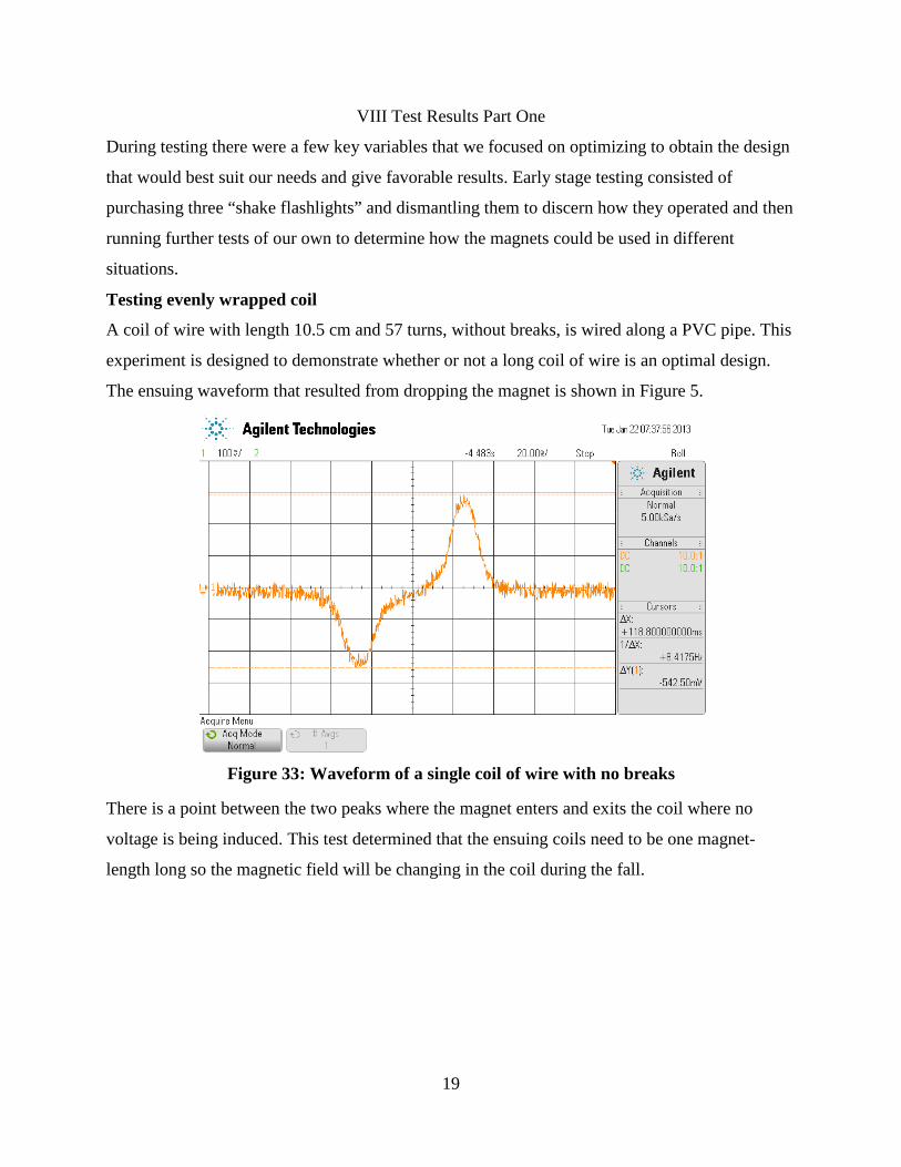
Testing evenly wrapped coil
A coil of wire with length 10.5 cm and 57 turns, without breaks, is wired along a PVC pipe. This
experiment is designed to demonstrate whether or not a long coil of wire is an optimal design.
The ensuing waveform that resulted from dropping the magnet is shown in Figure 5.
Figure 33: Waveform of a single coil of wire with no breaks
There is a point between the two peaks where the magnet enters and exits the coil where no
voltage is being induced. This test determined that the ensuing coils need to be one magnet-
length long so the magnetic field will be changing in the coil during the fall.

20
Testing coil wrapped in groups
Two coils of the same wire are placed at varying distances trying to find the location that allows
for most continual generation of voltage.
Figure 34: Two coils 1cm apart
In Figure 6 is the waveform for when the two coils are 1cm apart. In the waveform, as the
magnet enters the second coil it’s also leaving the first, which causes two opposing voltages
limiting the peak.
Figure 35: Two coils 5cm apart

21
Shown in Figure 7 is two coils are placed 5cm apart, the waveforms are almost identical, the
magnitudes are bigger as time goes along because the magnet has gained velocity as it fell. The
coils are placed such that the voltages aren’t interfering with each other. There is also is no lost
time where the magnetic field isn’t changing.
Figure 36: Two coils placed 8.3cm apart
In Figure 8, the coils are placed 8.3cm apart, the results are similar but there is lost time where
there is not voltage being generated.
Figure 37: Two coils placed 20cm apart

22
In Figure 9 the two coils are placed far enough where the magnet falling through the coils and
creates two separate peaks not affecting each other.
The tests showed that placing the coils apart yielded better results and placing the coils 5cm from
each other would yield the best waveforms without interference. Using that information it was
determined that using 3 individual wires with intermittent coils would be best, using either one
could or two coils would leave wasted space along the pipe. By using three coils wound adjacent
to each other there is enough distance between a single set of coils to not allow for interference,
yet all the wire is compact and there is no lost space. A concept of the wire design is shown
below in Figure 10 where the different color circles represent different sets of wire 2.7cm long.
Figure 38: Concept of a three wire design
After the concept of a three-coil winding was devised, the test PVC pipe was wired similarly to
the design shown in Figure 10. The test was repeated in similar fashion by dropping a magnet
through the coils and displaying the waveform on the oscilloscope. However since the
oscilloscope only has two inputs, the waveforms had to be saved and recalled and the test
repeated for the missing coils. The resulting waveforms are shown in Figure 11.
*
*
*
*

23
Figure 39: Three wire design waveform output
The results were better than expected, although there is a noticeable “dead-zone” in each, and it
progressively gets bigger as the magnet passes through the coils. This is due to us using a 3cm
length coil instead of a 2.7cm and each coil adds 0.3cm so the dead zone will only get larger.
When the device is built more attention will be put forth to ensure accuracy.
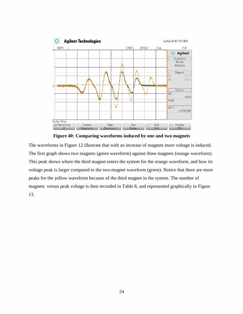
Testing with multiple magnets
In order to test multiple magnets, the three wire concept was connected to an oscilloscope so
only one wire of the three was being monitored. A magnet was dropped through the pipes and
output of the wire is the green waveform displayed in Figure 12. Then two magnets are dropped
through, separated by a wooden dowel cut to a length such that the two magnets enter coils of the
same wire simultaneously. This waveform is the yellow waveform shown in Figure 12.
24
Figure 40: Comparing waveforms induced by one and two magnets
The waveforms in Figure 12 illustrate that with an increase of magnets more voltage is induced.
The first graph shows two magnets (green waveform) against three magnets (orange waveform).
This peak shows where the third magnet enters the system for the orange waveform, and how its
voltage peak is larger compared to the two-magnet waveform (green). Notice that there are more
peaks for the yellow waveform because of the third magnet in the system. The number of
magnets versus peak voltage is then recorded in Table 8, and represented graphically in Figure
13.

25
Figure 41: Magnet Count versus Voltage
Magnet Count Peak Voltage
0 0 1 0.8625 2 1.54 3 2.58125
Table 18: Voltages versus number of magnets
y = 0.8421x - 0.0172
-0.5
0
0.5
1
1.5
2
2.5
3
0 0.5 1 1.5 2 2.5 3 3.5
Mea
sure
d Vo
ltag
e
Numbe of Magnets
Magnet Count versus Voltage

26
IX Development and Construction
Piping Material:
• The PVC pipe was purchased in 10ft increments and cut into four 2.5ft sections using a
ban-saw.
• The Acrylic pipe was purchased in 3ft sections pre-cut.
Wire and PVC pipe:
Experiments found that 5cm between coils yielded the best theoretical output waveforms, and
since there is three phases it was determined that 2.5cm per coil would be ideal. The PVC pipe
was fixed on one end to a drill with the highest rotational speed of 2000rpm, and on the other end
it was hanging loose to a metal screw emanating from the wall. A picture of this set-up can be
seen in Figure 14. The idea was that the wire would be stuck to a single point on the PVC pipe
and the drill would spin at full speed, spinning the PVC pipe around wrapping the wire around
the pipe. The drill was spun at full speed (2000rpm) for 1 minute and 30 seconds, or for 3000
rotations. The circumference of the pipe is:
34
"∗ 2.54 𝑐𝑚𝑖𝑛 ∗ 3.14
100 𝑐𝑚𝑚 = 𝟎.𝟎𝟓𝟗𝟖 𝒎
Equation 2: Calculation of length of wire
So with 3000 rotations around a 0.0598m circumference it would equate to 179.4m of wire used
per coil. Since there was roughly 14,484m (9 miles) of wire purchased, 3 pipes and 3 phases per
pipe, there would roughly need to be 9 coils per phase per pipe.

27
Figure 42: Mechanism for wiring pipe
Acrylic Pipe Fittings:
The bushing was fitted into the acrylic pipe as seen in Figures 15 using silicone glue. It took
three hours for the glue to dry and for the seal to be watertight. Once the glue was dried, the
bushing was fitted with a rubber cork that was large enough to be fit securely in the bushing, yet
allow enough space to be pulled out by hand. That is it didn’t lie flush with the bushing, which
can be seen in Figure 15.
Figure 43: Bushing and cork used to make pipe watertight
The data logger was larger than the inner circumference of the bushing, and as a result the
bushing had to be filed down to allow for the data logger to be entered. This can be seen in
Figure 16 as marked by the red circles.

28
Figure 44: Bushing filed down
Shown in Figure 17 is the data logger system inside the Acrylic pipe. The acrylic pipe was
intentionally selected long enough to allow for this space for the data logger to fit. The data
logger needed a 9V battery, which is shown in Figure 17.
Figure 45: Data logger and circuitry inside acrylic pipe

29
In order to view the data logger functioning properly (signified by two flashing LEDs on the data logger) a hole was cut into the outer piping so it can be observed through the acrylic pipe. As shown in Figure 18.
Figure 46: Hole cut into outer piping
The complete design fitted together can be seen in Figure 18
Figure 47: Ocean generator

30
X Test Results Part Two
Testing Continuity
After the three legs of the generator were built the wires was checked for continuity, by
measuring the resistance of each wire for each phase. Using the American Wire Gauge standard,
the resistance of the wire was converted to feet. The results are displayed below in Table 9. The
names of the branches are named Antigua, Bermuda, Cyprus.
Phase Antigua [Ω] Bermuda [Ω] Cyprus [Ω] A 671 2332 DNE B 2208 2035 DNE C 1700 DNE DNE Antigua [ft] Bermuda [ft] Cyprus [ft]
A 1617.66 5621.99 DNE B 5323.05 4905.98 DNE C 4098.36 DNE DNE
Table 19: Values of resistance and length for all coils of wire
Complications arose in all branches, most notably with both Antigua and Cyprus. Both branches
had significant breaks in wire. Antigua was soldered and mostly recovered. There were some
losses in Phases A and C. With Bermuda there was a single break in Phase B that was easily
soldered to complete the phase, however Phase C was lost completely when other coils covered
the break between two wires in that Phase. There were several complications in Cyprus where
several breaks were lost and were not able to be recovered to be soldered.
Finding Maximum Voltage
It was determined that Bermuda would be the best Branch moving forward since it had the most
complete branches, and the data logger purchased was only logging a single branch at a time. In
lab to two working Phases (Phase A and B) were tested by dropping all three Magnets vertically
through the pipe, with its leads connected to the two inputs of an oscilloscope. Seen in Figure 13
is the result of this experiment. The green waveform is Phase A and the orange is Phase B. It can
be seen that the waveforms don’t match exactly, due to the uneven amounts of length in the
Phases. The maximum amount of voltage was found in Phase A where it was 81.62V peak-to-
peak. Comparing the peaks individually, the difference arises from inaccurate spinning method.
Using a drill and stopwatch to count turns isn’t very accurate, and shows that it doesn’t yield
consistent results.

31
Figure 48: Waveforms of the Phases A and B of Bermuda
Testing to ensure the design is waterproof
The acrylic pipe was layered with silicone glue and bushings were placed on the end. Inside the
pipes paper towel was placed and corks were fitted into the holes of the bushings, so that the
device was watertight. A bucket was filled with water and each acrylic pipe was submerged and
moved around to simulate ocean movement. Each branch was checked for leaks by examining
the paper towel. No leaks were found.
Testing the data logger
The raw data was stored on an SD card via the data logger in .txt files. However, the data when
opened in Notepad was largely gibberish when binary values were expected. However, when
opened with the hex reader freeware “HxD” data was observable and then converted and graphed
thru a macro on Excel. This process, although, a bit cumbersome allowed for what looked like
gibberish in a notepad file to be converted to graphs that matched very closely to what was
expected based off the inputted waveforms.
32
After the data could be read in excel, accuracy was then tested. Using a DC power supply the
data logger’s inputs were placed across the power supply’s terminals and the power supply’s DC
output was increased in 0.1V increments from 0V to 5V. It was soon discovered that the data
logger could not log data below 0V and above its reference voltage of 3.3V.
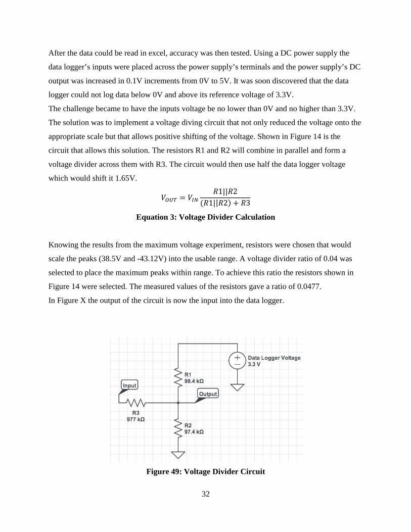
The challenge became to have the inputs voltage be no lower than 0V and no higher than 3.3V.
The solution was to implement a voltage diving circuit that not only reduced the voltage onto the
appropriate scale but that allows positive shifting of the voltage. Shown in Figure 14 is the
circuit that allows this solution. The resistors R1 and R2 will combine in parallel and form a
voltage divider across them with R3. The circuit would then use half the data logger voltage
which would shift it 1.65V.
𝑉𝑂𝑈𝑇 = 𝑉𝐼𝑁𝑅1||𝑅2
(𝑅1||𝑅2) + 𝑅3
Equation 3: Voltage Divider Calculation
Knowing the results from the maximum voltage experiment, resistors were chosen that would
scale the peaks (38.5V and -43.12V) into the usable range. A voltage divider ratio of 0.04 was
selected to place the maximum peaks within range. To achieve this ratio the resistors shown in
Figure 14 were selected. The measured values of the resistors gave a ratio of 0.0477.
In Figure X the output of the circuit is now the input into the data logger.
Figure 49: Voltage Divider Circuit

33
Testing the design with the data logger
After the voltage divider circuit was built and connected to the data logger, Phase A from
Bermuda was connected to an oscilloscope input and data logger input and randomly tilted back
and forth to produce a waveform. This waveform was induced by one magnet and is seen in
Figure 15 and the waveform produced by the data logger is seen Figure 16.
Figure 50: Oscilloscope capture of a random waveform
Figure 51: Data logger output of a random waveform
-10
-8
-6
-4
-2
0
2
4
6
0 1 2 3 4
Volt
age
(V)
Time (seconds)
34
-10
-8
-6
-4
-2
0
2
4
6
0 0.5 1 1.5 2 2.5 3 3.5 4
Volt
age
(V)
Time (seconds)
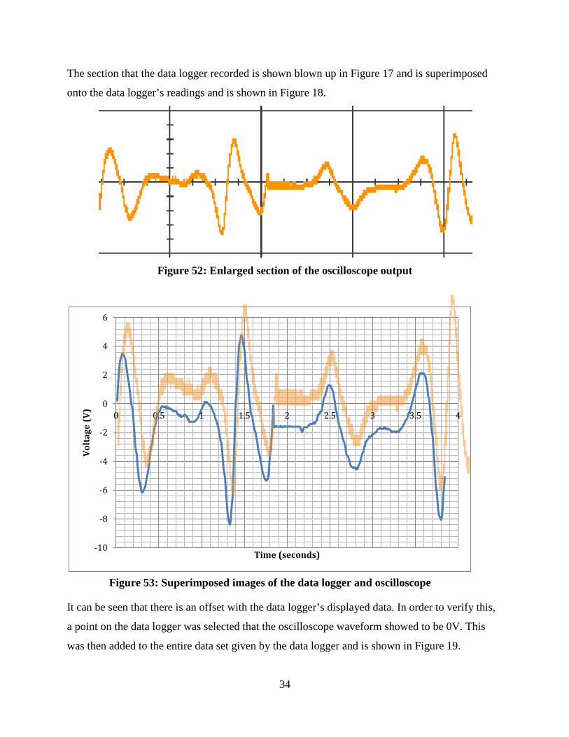
The section that the data logger recorded is shown blown up in Figure 17 and is superimposed
onto the data logger’s readings and is shown in Figure 18.
Figure 52: Enlarged section of the oscilloscope output
It can be seen that there is an offset with the data logger’s displayed data. In order to verify this,
a point on the data logger was selected that the oscilloscope waveform showed to be 0V. This
was then added to the entire data set given by the data logger and is shown in Figure 19.
Figure 53: Superimposed images of the data logger and oscilloscope

35
-10
-8
-6
-4
-2
0
2
4
6
8
0 0.5 1 1.5 2 2.5 3 3.5 4
Time
Figure 54: Super imposed images of the original data logger output, the oscilloscope image, and the fixed data logger output.

36
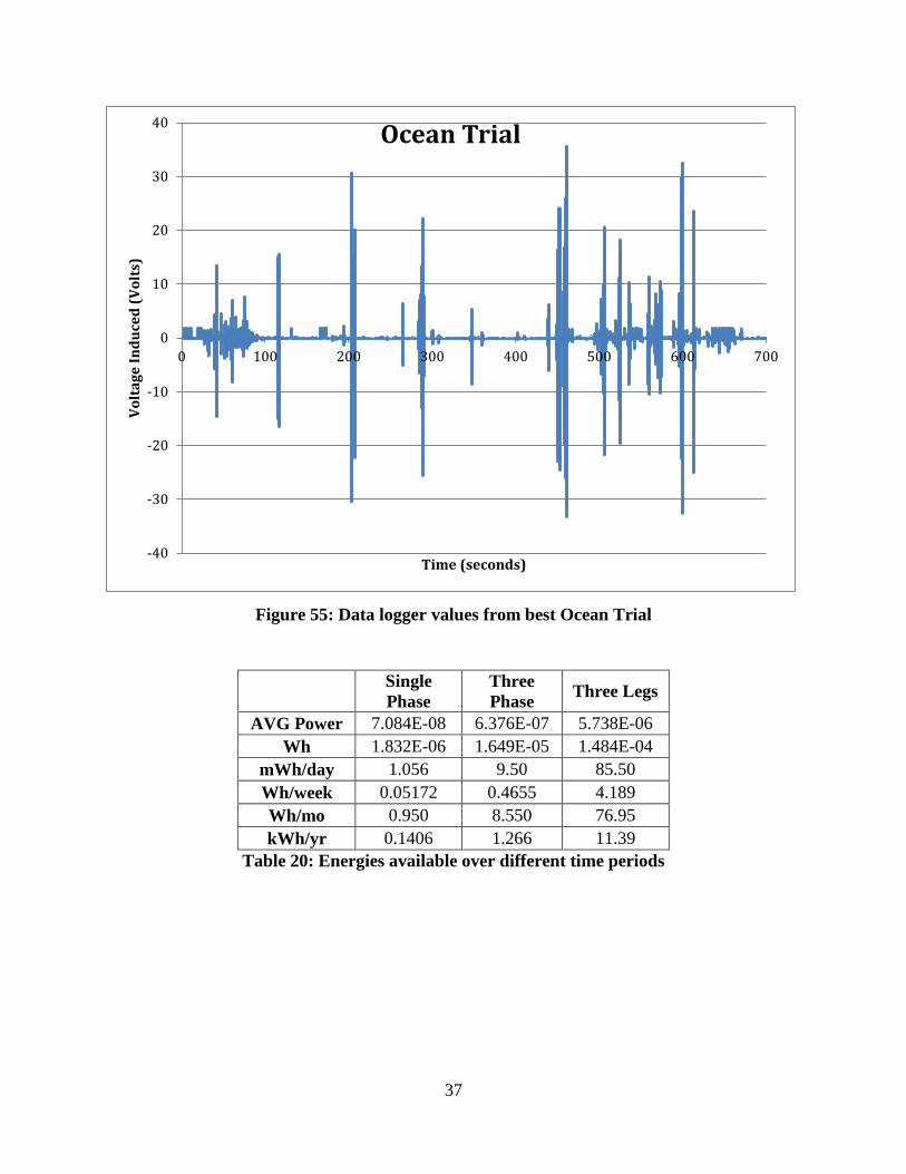
XI Test Results Part Three
The above graph shows a full ocean trial in which the datalogger was turned on and the
device was carried down to the water from the beach and pulled out into the deeper water. This
accounts for the first two minutes and all of the relatively small fluculations. Then the next 500
seconds (120 to 620 seconds) show waves causing the magnets to propogate thru the pipe and
induce emf. In the conception of this design one of the strengths of using wave technology was
that unlike solar or wind it would generate all day regardless of sun or wind exposure. However,
this generalization is not entirely true because as the graph shows there are periods of up to 40
seconds where there were not any waves of significant magnitude to tilt the design to a sufficient
angle to cause the magnets to slide.
Testing the device out in the ocean generated a maximum voltage of ~68 Vp-p, however this
quantity on its own is nearly useless because it is entirely dependent on the resistance it is across.
In this case, with the resistance per leg per phase known a more useful metric of power [W] can
be calculated. A matched load with a complex conjugate (an opposite reactive load) allows for
the greatest power transfer and knowing that there will be a voltage divider across the winding
resistance and the load allows the following equation to be derived:
𝑃𝑚𝑎𝑥 =�𝑉2�
2
𝑅=
14𝑉2
𝑅
Equation 4: Finding Max Power
Inserting values from the peak voltage generated yields
𝑃𝑚𝑎𝑥 = (0.25) ∗(35.4)2
2332= 134.34 𝑚𝑊
Equation 5: Inserting values to find Max Power
However, this metric again is not extremely useful because this is just a measure of max
instantaneous power transfer on one phase of one leg. To give a more accurate illustration of the
power generated, the average voltage generated over an entire trial can be used in place of the
max power. Extrapolating this data the following table was generated:
37
Figure 55: Data logger values from best Ocean Trial
Single Phase
Three Phase Three Legs
AVG Power 7.084E-08 6.376E-07 5.738E-06 Wh 1.832E-06 1.649E-05 1.484E-04
mWh/day 1.056 9.50 85.50 Wh/week 0.05172 0.4655 4.189 Wh/mo 0.950 8.550 76.95 kWh/yr 0.1406 1.266 11.39
Table 20: Energies available over different time periods
-40
-30
-20
-10
0
10
20
30
40
0 100 200 300 400 500 600 700
Volt
age
Indu
ced
(Vol
ts)
Time (seconds)
Ocean Trial
38
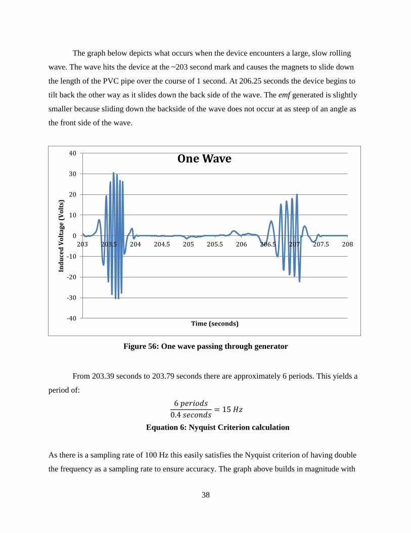
The graph below depicts what occurs when the device encounters a large, slow rolling
wave. The wave hits the device at the ~203 second mark and causes the magnets to slide down
the length of the PVC pipe over the course of 1 second. At 206.25 seconds the device begins to
tilt back the other way as it slides down the back side of the wave. The emf generated is slightly
smaller because sliding down the backside of the wave does not occur at as steep of an angle as
the front side of the wave.
Figure 56: One wave passing through generator
From 203.39 seconds to 203.79 seconds there are approximately 6 periods. This yields a
period of:
6 𝑝𝑒𝑟𝑖𝑜𝑑𝑠
0.4 𝑠𝑒𝑐𝑜𝑛𝑑𝑠= 15 𝐻𝑧
Equation 6: Nyquist Criterion calculation
As there is a sampling rate of 100 Hz this easily satisfies the Nyquist criterion of having double
the frequency as a sampling rate to ensure accuracy. The graph above builds in magnitude with
-40
-30
-20
-10
0
10
20
30
40
203 203.5 204 204.5 205 205.5 206 206.5 207 207.5 208
Indu
ced
Volt
age
(Vol
ts)
Time (seconds)
One Wave

39
each peak and trough due to the magnets picking up speed as they move down the pipe and then
ending with a slight jarring as it bumps into the other end of the pipe which causes the non-
sinusoidal bumps at the end of each sinusoid.

40
XII Conclusion
The overall concept idea of the project was a resounding success in that it operated
exactly as expected. However, the efficacy of the project is questionable at this scale especially
considering the resources necessary for the device. One of the major goals was to be sustainable
and while the transfer of energy is very sustainable because it is coming from ocean waves due
to gravity, the production of the devices must be taken into account as well. In the current design,
9 N42 Magnets are being used as well as over 9 miles of magnet wire. If one were to scale up
this project in order to obtain more power, it would have to be taken into consideration whether
or not using rare earth magnets and a great quantity of copper in the wire is worth the power
generated.
Based off the data on a yearly basis each device can generate approximately 11.4 kWh
per year which is a mere fraction of what is used by individual people in most developed
countries around the world. If the project were to be scaled up by adding more devices in the
future things that should be taken under consideration include finding a more effective way of
winding the pipes, how to store or transmit the power, and how to minimize the ecological
footprint of producing the device.

41
XIII Bibliography [1] Brad Linscott, Renewable Energy - A Common Sense Energy Plan, Tate Publishing, 2011,
Ch1, pp1-pp65
[2] Letter from George V. Voinovich, United States Senator, Ohio, to Bradford S. Linscott:
America’s Energy Policies, May 1, 2009.
[3] Louise I. Gerdes, Wave and tidal power at issue, GALE Cengage Learning, 2011, pp1-pp15
[4] http://oceanservice.noaa.gov/facts/population.html
[5] http://www.uni-bell.org/environment.html
[6] Magnetic Materials Producers Association, Standard Specifications for Magnet Materials,
Magnetic Materials Producers Association
[7] D. O’Sullivan and A. Lewis, Generator Selection and Comparative Performance in Offshore
Oscillating Water Column Ocean Wave Energy Converters, IEEE Transactions On Energy
Conversion, VOL. 26, NO. 2, June 2011
[8] http://www.el.angstrom.uu.se/forskningsprojekt/WavePower/Lysekilsprojektet_E.html

![L 29 Electricity and Magnetism [6] Review Faraday’s Law of Electromagnetic Induction induced currents electric generator eddy currents electromagnetic](https://img.dokumen.tips/doc/110x75/56649e765503460f94b7766d/l-29-electricity-and-magnetism-6-review-faradays-law-of-electromagnetic.jpg)

![L 28 Electricity and Magnetism [6] magnetism Faraday’s Law of Electromagnetic Induction –induced currents –electric generator –eddy currents Electromagnetic](https://img.dokumen.tips/doc/110x75/56649d035503460f949d6537/l-28-electricity-and-magnetism-6-magnetism-faradays-law-of-electromagnetic.jpg)
![L 28 Electricity and Magnetism [6] magnetism Faradays Law of Electromagnetic Induction induced currents electric generator eddy currents Electromagnetic](https://img.dokumen.tips/doc/110x75/5a4d1b7c7f8b9ab0599b95a1/l-28-electricity-and-magnetism-6-magnetism-faradays-law-of-electromagnetic-induction.jpg)


