Embed Size (px)
Citation preview
Océ �Arizona 30 Sign Printer User Guide
Large-Format Piezo Inkjet Printer
Revision B · January 2002

Océ Display Graphics Systems
© 2002 ALL RIGHTS RESERVED

Table of Contents
Copyright and Document History ...............................................................ivProduct Support, Documentation and Service ..............................................ivProduct Compliance and Standards .............................................................vi
1 Introduction to the Arizona 30 Sign Printer....................... 1-1
Getting Familiar With Your Arizona 30..................................................... 1-1Scope of This Guide .......................................................................... 1-1Printer Overview ............................................................................... 1-1Technical Specifications ..................................................................... 1-1Supported Media Specifications.......................................................... 1-2Ordering Supplies.............................................................................. 1-2Anatomy of the Arizona 30 ................................................................ 1-3
Important Safety Information For All Users............................................... 1-4Ink Safety.......................................................................................... 1-4Mechanical Safety .............................................................................. 1-5Electrical Safety ................................................................................. 1-5
2 Preparing the Arizona 30 for Operation ............................. 2-1
Connecting the Arizona 30 to Power and Data .......................................... 2-1Connecting the Printer to Power ........................................................ 2-1Selecting the Correct Voltage.............................................................. 2-2Data Connection ............................................................................... 2-2
Installing the Waste Bottle........................................................................ 2-3Powering Up the Arizona 30..................................................................... 2-3Loading Media ........................................................................................ 2-4Using the Media Takeup Roller ................................................................ 2-6Operating the Dryer................................................................................. 2-6Operation of the Ink System..................................................................... 2-7
Interlock Switch................................................................................. 2-7Removing Residual CGS-80 From Ink System .................................... 2-8Filling the Ink Tanks ......................................................................... 2-9Priming the Ink System.................................................................... 2-10
Head Testing and Color Alignment ........................................................ 2-12Prime Test Pattern........................................................................... 2-12Alignment Test Pattern .................................................................... 2-12Swath Adjustment ........................................................................... 2-13Column Adjustment ........................................................................ 2-14Row Adjustment.............................................................................. 2-14

Arizona 30 Sign Printer User Guide �
ii see copyright, disclosure, use and duplication information on pg iv 47917-B
Bidirectional Alignment ................................................................... 2-15Width Adjustment ........................................................................... 2-17
3 Using the Control Panel...................................................... 3-1
Control Panel Functions........................................................................... 3-1Navigating the Menus .............................................................................. 3-2
Material Width and Length ................................................................ 3-5Set Origin.......................................................................................... 3-5Print Quality ..................................................................................... 3-5Number of Passes............................................................................... 3-6Print Direction .................................................................................. 3-6Re-plot .............................................................................................. 3-6Load Default ..................................................................................... 3-7Save Default ...................................................................................... 3-7Dry Time .......................................................................................... 3-8Park Time ......................................................................................... 3-8Swath Delay ...................................................................................... 3-8Edge Distance.................................................................................... 3-9Edge Print ......................................................................................... 3-9Set Serial Port .................................................................................... 3-9External Command.......................................................................... 3-10Align Heads..................................................................................... 3-10Saturation Adjustment ..................................................................... 3-14Flush Buffer..................................................................................... 3-15Display Units................................................................................... 3-15Advance Distance............................................................................. 3-15
Using the F1 Cleaning Menu.................................................................. 3-15Soft Cleaning................................................................................... 3-16Hard Cleaning................................................................................. 3-16Ink Clearing .................................................................................... 3-17Ink Priming..................................................................................... 3-17Head Flushing ................................................................................. 3-17
Cleaning the Maintenance Station........................................................... 3-17Printer Operating Modes ........................................................................ 3-18
2-Pass Mode .................................................................................... 3-184-Pass Mode .................................................................................... 3-188-Pass Mode .................................................................................... 3-18
Error Codes ........................................................................................... 3-18

� Copyright, Company Information and Laser Safety Standards Compliance
47917-B see copyright, disclosure, use and duplication information on pg iv iii
List of Figures
Figure 1-1 Front exterior view of the Arizona 30 .................................................... 1-3Figure 1-2 Rear exterior view of the Arizona 30...................................................... 1-4Figure 2-1 Rear view of right cover. ....................................................................... 2-1Figure 2-2 Attaching the waste bottle tubes to the waste ports ................................. 2-3Figure 2-3 Removing the sticker from he vent hole on waste bottle lid..................... 2-3Figure 2-4 Putting end caps and media roll on media shaft ..................................... 2-4Figure 2-5 Correct positioning of end caps............................................................. 2-4Figure 2-6 Incorrect positioning of end caps........................................................... 2-4Figure 2-7 Correct position of screw on locking collar ............................................ 2-5Figure 2-8 Media in position for loading and location of pinch lever ....................... 2-5Figure 2-9 Positioning takeup core and location of takeup power switch.................. 2-6Figure 2-10 Tilting dryer back for media loading; also shows dryer power
module under dial .......................................................................................... 2-7Figure 2-11 Carriage with cover removed............................................................... 2-9Figure 2-12 Ink tanks and their respective ink colors .............................................. 2-9Figure 2-13 View of the carriage through the maintenance station access door ....... 2-10Figure 2-14 Manually priming the ink system ...................................................... 2-11Figure 2-15 Prime Test Pattern .......................................................................... 2-12Figure 2-16 Alignment Test Pattern ................................................................... 2-13Figure 2-17 Bi-directional Alignment Test Pattern .............................................. 2-16Figure 3-1 Control panel....................................................................................... 3-1Figure 3-2 Menu Flow Chart (1 of 2) ................................................................... 3-3Figure 3-3 Menu Flow Chart (2 of 2) .................................................................. 3-4
List of Tables
Table 3-1 Functions of the control panel keys ........................................................ 3-1

Arizona 30 Sign Printer User Guide �
iv see copyright, disclosure, use and duplication information on pg iv 47917-B
Copyright
© 2002 Océ. All rights reserved.
This document contains information proprietary to Océ, to its subsidiaries, or to third parties towhich Océ may have a legal obligation to protect such information from unauthorized disclosure,use or duplication. Any disclosure, use, or duplication of this document or of any of theinformation contained herein for other than the specific purpose for which it was disclosed isexpressly prohibited, except as Océ may otherwise agree to in writing. Due to continuing researchand product improvements, features or product specifications may change at any time withoutnotice.
Document History
Date Release Doc. No. Revision Revision Summary
Oct. 24, 2001 Production 47917 A Temporary manual for new product.
Dec. 19, 2001 Production 47917 BCompletely revised manual; changed Gretag toOcé.
Product Support, Documentation and Service
For further information on documentation and support for your Arizona 30 Sign Printer or forinformation on other Océ Display Graphics Systems products, please contact:
Océ Display Graphics Systems13231 Delf Place, #501Richmond, British Columbia, Canada V6V 2C3Phone: (604) 273-7730 Fax: (604) 273-2775Web: http://www.dgs.oce.comTech Support Site: http://www.dgs.oce.com/rgi/tech/index.html
Comments on this manual?Please forward to the above address, marked “Attention: Technical Writer”.
Océ maintains a comprehensive support structure for its Arizona® customers. Upon installation ofyour printer, you will be provided with the name of the sales and service office responsible foryour account. Record this information, along with the serial number of your Arizona 30 SignPrinter. Always report service problems to the office assigned to your account at installation.Contacting the factory directly may cause unnecessary delays in resolving your service issue.

� Copyright, Company Information and Laser Safety Standards Compliance
47917-B see copyright, disclosure, use and duplication information on pg iv v
US and Canadian Customers:
Océ Display Graphics Systems Service: 1-800-456-347313231 Delf Place, Building #501 Fax: 604-232-3154Richmond, British Columbia, Canada Parts Orders: V6V 2C3
European Customers:
Océ Display Graphics Systems Service Tel: 44-0-1628-519720
6 Waltham Park Service Fax: 44-0-1628-519750
Waltham Road Parts Inquiries: 44-0-1628-519736
White Waltham Parts Orders Fax: 44-0-1628-519751
Berkshire SL6 3TN
England
Asia Pacific Customers:
Océ Display Graphics Systems Service: 81-3-5484-8033
Grand Palace Tamachi 601 Fax: 81-3-5484-2071
4-9-18 Shibaura, Minato-ku
Tokyo, Japan 108-0023
Other:
Your regional distributor
When you call one of our customer service numbers you will be provided with telephone technicalsupport. Outside of office hours, you can leave a message and your call will be returned the nextworking day. When you call, identify yourself as a Arizona® customer and provide the followinginformation:
� The serial number of your Arizona 30� Your company name� Your name
� Your telephone number� Nature of the problem
If we are unable to resolve your problem over the telephone, field engineers can be dispatched toyour site to conduct repairs. Service visits are paid for by the customer, either under a maintenanceagreement or by purchase order or prepayment. Time and material rates are charged for anyservice not covered under a maintenance agreement. Before calling to report a problem, gather asmuch information about the problem as possible and have it ready to provide to the customer carecenter engineer. The more information you can provide initially, the more quickly the problemcan be corrected.

Arizona 30 Sign Printer User Guide �
vi see copyright, disclosure, use and duplication information on pg iv 47917-B
Product Compliance and Standards
Electromagnetic Compatibility
This equipment generates, uses and radiates radio frequency energy and if not installed and usedas designed or intended, may cause interference to radio communications. This equipment hasbeen tested and found to comply with the limits for a Class A digital device. This equipment hasbeen designed to provide reasonable protection against such interference when operated incommercial environments. Operation of this equipment in a residential area may causeinterference, in which case the user, at his own expense, is required to take whatever measures arerequired to correct the interference.
The user is cautioned that changes and modifications made to the equipment without approval ofthe manufacturer could void the user’s authority to operate this equipment. It is suggested that theuser use only shielded and grounded cables to ensure compliance with FCC rules.
United States Of America - FCC Canada - ICES-003
This device complies with Part 15 of the FCCRules. Operation is subject to the followingtwo conditions: (1) This device may not causeharmful interference, and (2) This devicemust accept any interference received,including interference that may causeundesired operation.
This Class A/B digital apparatus meets allrequirements of the Canadian Interference-Causing Equipment Regulations.
Cet appareil numerique de la classe A/Brespecte toutes les exigences du Reglement surle materiel brouilleur du Canada.
European Community - EMC
This device complies with Class A/B emission limits in accordance with EN55022.
Electromagnetic compatibility - Emissions 89/336/EECElectromagnetic compatibility - Immunity 89/336/EEC
Electrical Safety
This equipment has been tested and found to comply with the following electrical safetystandards:
North America
Canada CSA 950
United States of America UL 1950
European Community
EN60950 Low Voltage Directive 73/23/EEC
EN60204-1 Machinery Directive 93/68/EEC
End of Section

� Introduction to the Arizona 30 Sign Printer
47917-B see copyright, disclosure, use and duplication information on pg iv 1-1
1 Introduction to the Arizona 30 Sign Printer
Getting Familiar With Your Arizona 30
Scope of This Guide
This users guide describes your Arizona 30 Sign Printer in detail, including technicalspecifications, information on ordering supplies, functional anatomy of the printer, safetyinformation, instructions for calibrating the printer and preparing it for its first use, using thecontrol panel. It also includes error codes that may be encountered during use, along withpossible causes and corrective measures. This guide does not included information on regularmaintenance procedures that are integral to the functioning of the printer. Before using yourArizona 30, you must thoroughly read and understand the accompanying Arizona 30 SignPrinter Maintenance Guide (48210) and Arizona 30 Sign Printer Maintenance Procedures QuickReference Card (47813).
Printer Overview
Your Arizona 30 Sign Printer is a state-of-the art wide-format color piezo inkjet printer. It is aproduction unit designed to print full color images on a variety of 3M media used in thegraphics production industry.
The Arizona 30 can print up to six process colors at a time using 3M inks on media up to 64”(1625 mm) wide with a print width up to 62” (1575 mm). With six process colors (CYMK plusLt Cyan and Lt Magenta), your Arizona 30 can print vibrant, durable images with smootherlight color tones in 360 dpi (dots per inch).
Technical Specifications
Printing Method: Six-color drop-on-demand piezoelectric inkjet, 1 print head per color
Resolution: 360 dpi
Print Mode/Speed: Two-pass bidirectional: 34 square feet an hourFour-pass bidirectional: 18 square feet an hourEight-pass bidirectional: 9 square feet an hour
Media: Variety of 3M Vinyl, banner and paper-based media for signs, fleetgraphics and backlit signs
Media Handling: Roll- or sheet-fed direct-imaging process. Floor-standing print stationwith stand, basket and take-up roll
Media Width: 64 inches (1.57 meters) maximum
Image Width: 62.282 inches maximum. 4 inches minimum

Arizona 30 Sign Printer User Guide �
see copyright, disclosure, use and duplication information on pg iv 47917-B1-2
Inks: 3M Scotchcal Piezo inkjet, series 6000, solvent-based pigmented inks inblack, cyan, light cyan, magenta, light magenta and yellow, in six 180 mltanks
Buffer Size: 256 MB (200 MB used for image file)
Interface: IEEE-1284 parallel and RS-232 serial ports
Software: PosterShop color production software (sold separately)
Power Supply: 116-220 VAC, 50/60 Hz, 250 Watts maximum
Environment: Operating Range Optimum Storage
Temperature: 65º to 80º F (18.3º to 26.7º C) 60º to 90º F (15.6º to 32.2ºC)Humidity: 40% to 60% RH non-condensing 10% to 80% RH non-condensingAltitude: Up to 8,000 feet (2,438 meters) Up to 8,000 feet (2,438 meters)
Dimensions: 88” Wide x 44” High x 24” Deep (223.5 cm x 111.8 cm x 61.0 cm)
Weight: 140 lb (63.5 kg), printer only, uncrated.30 lb (13.6 kg), dryer only, uncrated.325 lb (147.4 kg), printer and dryer, crated.
Supported Media Specifications
Océ Display Graphics Systems and/or the respective media manufacturer have tested andauthorized the use of certain media materials. These materials have been certified to perform atacceptable levels on a properly functioning system. Please consult the Tech Support web site athttp://www.dgs.oce.com/rgi/tech/index.html for a current list of qualified media.
Ordering Supplies
Océ Display Graphics Systems works closely with the manufacturers of imaging media toidentify the inks and media that work best with Océ printers. Océ supplies are extensively testedin our laboratories before being approved for shipment to our customers. Listed below are theprinter supply phone and fax numbers for ordering new media and ink. The appropriateCustomer Service numbers and web site addresses of Océ Display Graphics Systems and 3M arealso provided for your convenience.
Order Phone & Fax Numbers:
Océ Display Graphics Systems Ink Supplies & Media
� Toll Free: 1-888-744-5585
� Tel: 1-408-220-1504
3M Commercial Graphics Division Media Supplies
� Toll Free: 1-800-374-6772
� Fax-on-Demand: 1-800-364-0768

� Introduction to the Arizona 30 Sign Printer
47917-B see copyright, disclosure, use and duplication information on pg iv 1-3
Customer Service Phone & Fax Numbers:
Océ Display Graphics Systems Help Desk
� Toll Free: 1-800-456-3473
3M Commercial Graphics Division
� Toll Free: 1-800-328-3908
For a Description of Supplies:
Océ Display Graphics Systems
� http://www.dgs.oce.com/rgi/supplies/index.html
3M Commercial Graphics Division
� http://products.3m.com/usenglish/scotchprint/scotchprint.jhtml?powurl=0NGXS93FWQgeK9JT0N94GJgeGST1T4S9TCgv
Anatomy of the Arizona 30
CONTROL PANEL
TOP FRONT COVERDRYER TEMPERATURE
DIAL
MAINTENANCE STATION
ACCESS DOOR
MEDIA TAKEUP
ROLLER
MEDIA COLLECTION
BASKET
DRYER
MEDIA TAKEUP
SWITCH
LEFT SIDE
RIGHT SIDE
Figure 1-1 Front exterior view of the Arizona 30

Arizona 30 Sign Printer User Guide �
see copyright, disclosure, use and duplication information on pg iv 47917-B1-4
REAR RIGHT COVER PINCH LEVER
MEDIA SHAFT
POWER SWITCH AND VOLTAGE SELECTOR
WASTE BOTTLE
MALE PLUG
Figure 1-2 Rear exterior view of the Arizona 30
Important Safety Information For All Users
Ink Safety
The Arizona 30 uses solvent-based inks and the liquid and the fumes are both combustible. Inaddition, the inks may:
� cause eye irritation� cause skin irritation upon prolonged or repeated contact� be absorbed through the skin� cause respiratory system irritation� cause nervous system impairment
Read and practice safety guidelines as outlines in the Material Safety Data Sheet (MSDS) foreach ink. Post the MSDS in the work area.

� Introduction to the Arizona 30 Sign Printer
47917-B see copyright, disclosure, use and duplication information on pg iv 1-5
Personal Safety
Any person handling inks should wear butyl rubber gloves, a protective apron, an NIOSH-approved respirator (half-mask organic vapor respirator) and safety glasses with side shields.
Dealing With Ink Spills on Surfaces
Observe precautions as noted above. Ventilate the area. Contain the spill and cover withabsorbent material. Collect spilled material and clean up residue with water. Place all waste in aclosed container; never release to sewer or waterways. Incinerate in an appropriate hazardouswaste facility.
Dealing With Ink Spills on Persons
Eye contact: immediately flush eyes with large volume of clean water. Get immediate medicalattention.
Skin contact: flush skin with large volume of clean water. If irritation persists, seek medicalattention.
Inhalation: remove person to fresh air. If not breathing, send for medical assistance andadminister artificial respiration. If breathing with difficulty, get immediate medical attention.
Swallowed: call a physician/poison control agency immediately. Only induce vomiting at theinstructions of a physician. Never give anything by mouth to an unconscious person.
Mechanical Safety
The dryer on the front of the Arizona 30 gets very warm to the touch. Although it is not likelyto cause burns, it has 3 warning stickers that change from yellow to red as its temperatureincreases.
Electrical Safety
Unless specifically instructed to do so, never perform any maintenance work inside the printerwithout first disconnecting it from the power supply by unplugging the power cord from thewall socket.
End of Section

Arizona 30 Sign Printer User Guide �
see copyright, disclosure, use and duplication information on pg iv 47917-B1-6
THIS PAGE INTENTIONALLY LEFT BLANK

� Preparing the Arizona 30 for Operation
47917-B see copyright, disclosure, use and duplication information on pg iv 2-1
2 Preparing the Arizona 30 for Operation
Because the end user will not unpack or assemble the Arizona 30, unpacking and assemblyinstructions are in a separate guide, the Arizona 30 Installation Guide (48020). Although theinitial setup of the printer will also be performed by a service engineer, information on the initialsetup is included here to help you understand the printer’s operation.
Connecting the Arizona 30 to Power and Data
The power and data connectors are located at the back of the right side cover (Figure 2-1).
POWER SWITCH
MAIN POWER INPUT
VOLTAGE SELECTOR
CLEAN/RUN SWITCH
AIR INJECTION PORT
WASTE OUTLET PORTS
INK TANKS
PRODUCT LABEL
PARALLEL
PORT
Figure 2-1 Rear view of right cover.
Connecting the Printer to Power
1. Connect one of the short power jumpers to the main power input (Figure 2-1) and thefemale power outlet on the right leg of the printer.
2. Connect the second power jumper to the plug on the side of the right leg and the power plugon the dryer.
3. Connect the main power cable to the male plug on the rear of the right leg of the printer andplug it into the wall socket.

Arizona 30 Sign Printer User Guide �
see copyright, disclosure, use and duplication information on pg iv 47917-B2-2
CAUTION Ensure that the external power cable will not be a tripping hazard.
CAUTION A good power ground connection is required for safe operation. In the event ofelectrical failure, a faulty ground line may result in electric shock. Use agrounded plug and connect to a power source with a proper groundconnection.
Selecting the Correct Voltage
To prevent damage to the printer and ensure that it operates correctly, you must set all fourvoltage selectors to the correct voltage for your power system.
There are two red voltage selector switches, one located on the power supply module at the rearof the right side of the printer (Figure 2-1) and the other next to the power supply module on thefront right underside of the dryer. To set the voltage with these switches, move them to the left(115V) or right (230V) position.
The Arizona 30 has two power modules, each with a voltage selector that must be set to thecorrect voltage (100-120V or 200-240V). One is located on the rear right leg of the printer standand the other is on the dryer, at the front right underside. On each power module, the currentvoltage selection is displayed in a small window on the power module. To change the voltageselection:
1. Insert a flathead screwdriver into the notch on the right side of the power module window,and pry it open.
2. After opening the window, pull the fuse box out and slide out the small circuit board.
3. Rotate it 180 degrees and slide it back in.
4. Replace the power module cover.
5. Verify that the correct voltage is displayed in the window.
CAUTION Incorrect voltage selection may result in damage to the printer.
Data Connection
Although the Arizona 30 has several data connector ports, only the parallel port is actuallyavailable for use (Figure 2-1).
This is a bidirectional parallel connector that operates at up to 2 MB of data transfer per second.This mode will supply data at a rate fast enough (400 MHz computers or better) for the fastestprinting modes on the printer.
Use only an IEEE-1284 rated parallel cable (provided) and, if your computer is a PC basedsystem, set the parallel mode in the BIOS setup to ECP or ECP/EPP.

� Preparing the Arizona 30 for Operation
47917-B see copyright, disclosure, use and duplication information on pg iv 2-3
Installing the Waste Bottle
The waste bottle sits in a bracket at the rear of the right stand leg. It has two tubes that must beconnected to the waste outlet ports at rear right of the printer, below the Run/Clean switch andthe air injection port (Figure 2-1 and Figure 2-2). Be sure to remove the plugs (if present) fromthe ports before you attempt to attach the tubes. Remove the sticker covering the vent hole on thewaste bottle lid (Figure 2-3).
Figure 2-2 Attaching the waste bottle tubes tothe waste ports
Figure 2-3 Removing the sticker from he venthole on waste bottle lid
Powering Up the Arizona 30
The Arizona 30 has 3 power switches: one on the rear right stand leg, one on the rear rightprinter cover and one underneath the front right corner of the dryer. The power switch on thestand is the main power switch; if this switch is not turned on, there will not be any poweravailable to the dryer or the printer. You can, therefore, use the rear right stand power switch tocontrol all 3 devices by leaving the printer and dryer switches in the on position and turning onlythe stand switch on and off.

Arizona 30 Sign Printer User Guide �
see copyright, disclosure, use and duplication information on pg iv 47917-B2-4
Loading Media
The Arizona 30 can accommodate roll media up to 64” (1625 mm) wide on 2” and 3” (51 mmand 76 mm) cores. Roll diameters can be up to 5½” (140 mm) behind the platen and 7½” (190mm) when mounted on the stand.
The Arizona 30 media system has been designed so that the media can be rolled with the printside facing either out or in. Keep this in mind when mounting the media roll. Most roll mediahave the printing surface on the outside surface of the roll.
1. Slide an end cap on the left end of the media shaft so that the narrow side of the end cap isfacing towards the centre of the shaft (Figure 2-4).
Figure 2-4 Putting end caps and media roll on media shaft
2. Slide the media roll on the opposite end of the shaft until it contacts the end cap. Do not slipthe end cap into the notches in the media core (Figure 2-5 and Figure 2-6).
3. Slide the other end cap onto the shaft until it makes contact with the roll core.
Figure 2-5 Correct positioning of end caps Figure 2-6 Incorrect positioning of end caps

� Preparing the Arizona 30 for Operation
47917-B see copyright, disclosure, use and duplication information on pg iv 2-5
4. Slide one locking media collar onto the shaft from each end and hand tighten the screws toprevent the media roll from shifting. Ensure that each collar goes on with the screw facingaway from the media roll (Figure 2-7).
5. At the rear of the printer, insert the right end of the assembled roll and shaft into the hole inthe chassis on the right side. Slide the shaft above and past the shaft stop until the shaft clearsthe chassis on the left side. Then insert the left end of the shaft into the hole on the leftchassis until it touches the stop. Drop both the ends of the shaft into the cradles on the sidechassis.
6. Loosen the screws on both locking collars. From the rear, slide the left collar all the way tothe left (towards the right cover) until it touches the side chassis (Figure 2-8) and tighten thescrew. Slide the media and right collar as far left as possible and tighten the right collar screw.
Figure 2-7 Correct position of screw on lockingcollar
Figure 2-8 Media in position for loading andlocation of pinch lever
7. Press down on the pinch wheel release lever to lift the pinch wheels off the media driverollers.
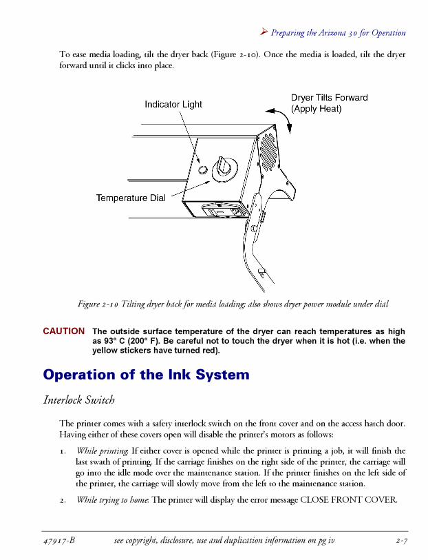
8. Tilt the dryer back to ease media loading (Figure 2-10).
9. Standing in front of the printer, insert the paper from the rear over the top of the rear platenand pull through to the front of the printer. Align the media square with the roll by pullingfrom the middle front edge of the media.
10. While holding the media square to prevent skewing, pull the pinch roller lever up to engagethe pinch wheels.
11. Tilt the dryer forward until it clicks into place.

Arizona 30 Sign Printer User Guide �
see copyright, disclosure, use and duplication information on pg iv 47917-B2-6
Using the Media Takeup Roller
1. You have the option of allowing imaged media to collect loose in the wire basket at the frontof the printer or using the black aluminum takeup shaft to roll the imaged media.
2. To use the takeup roller, place the takeup shaft through an empty media core. Place the shaftat the front of the printer, between the takeup core guide bearings (Figure 2-9).
3. Tape the leading edge of your media to the outer core.
4. The takeup core power switch is located on the front of the right leg (Figure 2-9). Theswitch has three positions: up is forward, centre is off and down is reverse. To use the takeuproller during printing, ensure that the switch is in the up position.
Figure 2-9 Positioning takeup core and location of takeup power switch
Operating the Dryer
The dryer temperature selector dial is located at the front right side of the dryer (Figure 1-1). Thedryer temperature setting required to dry your media depends on ambient temperature, humidity,print mode (affects output speed), volume of ink and the type of media being used. It will takesome experience for you to determine the appropriate temperature setting. Start by setting thedial to 4 and increase or decrease as needed.
Tuning the dial to off will not turn off the dryer fans. Leave the fans running to cool the dryerafter each use. After the dryer has cooled, turn off the fans by switching off the power at powerentry module.
� Preparing the Arizona 30 for Operation
47917-B see copyright, disclosure, use and duplication information on pg iv 2-7
To ease media loading, tilt the dryer back (Figure 2-10). Once the media is loaded, tilt the dryerforward until it clicks into place.
Figure 2-10 Tilting dryer back for media loading; also shows dryer power module under dial
CAUTION The outside surface temperature of the dryer can reach temperatures as highas 93° C (200° F). Be careful not to touch the dryer when it is hot (i.e. when theyellow stickers have turned red).
Operation of the Ink System
Interlock Switch
The printer comes with a safety interlock switch on the front cover and on the access hatch door.Having either of these covers open will disable the printer’s motors as follows:
1. While printing: If either cover is opened while the printer is printing a job, it will finish thelast swath of printing. If the carriage finishes on the right side of the printer, the carriage willgo into the idle mode over the maintenance station. If the printer finishes on the left side ofthe printer, the carriage will slowly move from the left to the maintenance station.
2. While trying to home: The printer will display the error message CLOSE FRONT COVER.

Arizona 30 Sign Printer User Guide �
see copyright, disclosure, use and duplication information on pg iv 47917-B2-8
3. While printer is idle: The motors will be disabled and the carriage will remain in its currentposition. At this time the carriage can be moved to any location on the printer, but the idleroutine is still active. This means that the print heads will occasionally eject ink and if thecarriage is positioned over the media, ink will get spit on the media. Once both covers areclosed the carriage will go move slowly back to the position it was in when the cover wasopened.
Removing Residual CGS-80 From Ink System
During the manufacturing process, the ink delivery system is cleaned with 3M CGS-80 solvent.When the machine arrives at the end user’s site, small amounts will still be in the system. Thissolvent will not cause any harm to the printer or its components, but it needs to be removed priorto adding ink. If the solvent mixes with the ink, it will change the characteristics of the ink.
1. Turn on the printer and let it boot up and home.
2. Press F2 to move the head carriage to the center of the platen. Remove the head carriagecover by removing the four Philips head screws on the sides of the cover (Figure 2-11). PressCANCEL to move the print head carriage back to the maintenance station.
3. Press F1.
4. Press until the display reads INK PRIMING.
5. Press .
6. Open the maintenance station access door and verify that the solvent is moving through thesystem (Figure 2-13).
7. After 60 seconds, press CANCEL.

� Preparing the Arizona 30 for Operation
47917-B see copyright, disclosure, use and duplication information on pg iv 2-9
Figure 2-11 Carriage with cover removed
Filling the Ink Tanks
1. From the rear of the printer, remove the black rubber caps from the six ink tanks along thetop of the right side cover.
2. Fill each of the six ink tanks with the correct color of ink (Figure 5-2). To prevent ink spills,only fill to about 0.5” (13 mm) below the rim.
3. After filling, replace the black rubber caps.
Figure 2-12 Ink tanks and their respective ink colors

Arizona 30 Sign Printer User Guide �
see copyright, disclosure, use and duplication information on pg iv 47917-B2-10
Priming the Ink System
1. Press F1.
2. Press until the display reads INK PRIMING.
3. Press . The priming pump will continue to pump until you press CANCEL.
4. Watch the ink reservoirs through the access hatch on the top of the right side cover (Figure2-13). When priming begins, you will see the reservoir inlet tubes fill with ink, followed bythe reservoirs. As priming continues, the reservoir outlet tubes will also fill. When you cansee that all six tubes going to the print heads have filled with ink, shut off the priming pumpby pressing the CANCEL key.
Figure 2-13 View of the carriage through the maintenance station access door
5. The printer will wait approximately three minutes after the priming pump shuts off for thesystem to stabilize. As the system stabilizes, the reservoirs should fill to between one thirdand one half full. This ink level must be maintained during printing operation for the inksystem to work properly.
6. Press F2 to move the carriage out of the maintenance station.
7. Check the ink level in all six reservoirs. The ink level should sit between the height of thebracket that the reservoir sits in and halfway up the reservoir (i.e. one third to one half full).

� Preparing the Arizona 30 for Operation
47917-B see copyright, disclosure, use and duplication information on pg iv 2-11
8. If all ink reservoirs are sufficiently filled, proceed directly to step 13. If not, any reservoir thatis not sufficiently filled will need to be manually primed using the air syringe - continue tostep 9.
9. Put on a protective pair of gloves. Unfold and place a single lint-free blotting cloth saturated(but not dripping) with 3M Scotchcal CGS-80 (CGS-80) under the print head carriage inpreparation for manually priming the system.
NOTE Never allow the lint-free cloth to come into contact with the print head nozzles.
NOTE Never use isopropyl alcohol on the print head nozzles.
10. Remove the reservoir and rotate it so that you can observe the ink level.
11. Pull the plunger on the air syringe about halfway back and insert the tapered front into theappropriate ink tank (Figure 2-14). Holding the black rubber cap to prevent pushing it intothe ink tank, inject the air from the syringe into the ink tank. Hold the plunger in tomaintain pressure until the correct ink level is attained. Remove syringe from ink tank.
Figure 2-14 Manually priming the ink system
12. Repeat steps 10 and 11 as required until each reservoir is filled to the proper level.
13. Ensure that all reservoirs are seated in their brackets.
14. Replace the carriage cover, remove the blotting cloth and press CANCEL to return thecarriage to the maintenance station.

Arizona 30 Sign Printer User Guide �
see copyright, disclosure, use and duplication information on pg iv 47917-B2-12
Head Testing and Color Alignment
Prime Test Pattern
This test uses all 120 functional nozzles (there 128 total per head, but eight are used forcalibration only) on each print head. The results will allow you to determine if any nozzles areblocked or misfiring.
1. Press HOME and allow the printer to home over a clean section of media. Once the printerhas completed this process, press MENU and verify that the displayed Y value (width ofmedia) is correct.
2. Press PRIME on the keypad to print the prime test pattern (Figure 2-15).
Figure 2-15 Prime Test Pattern
Inspect the prime test pattern, looking for white gaps in the color bars and missing vertical orhorizontal lines in the grid pattern. Both of these conditions indicate clogged or misfiring nozzlesand indicate that you will need to run one or more of the F1 cleaning cycles. If the print headsare all printing properly, proceed directly to alignment (if necessary) or production printing.
Alignment Test Pattern
After completing the prime test pattern and any necessary cleaning cycles:
1. Press to enter the main menu.
2. Press until the display reads ALIGNMENT TEST.
3. Press to print the alignment test (Figure 2-16).

� Preparing the Arizona 30 for Operation
47917-B see copyright, disclosure, use and duplication information on pg iv 2-13
Figure 2-16 Alignment Test Pattern
The alignment test pattern contains three sections: row adjustment, column adjustment andswath adjustment. Each is addressed below.
Swath Adjustment
This value is set to adjust the distance between passes. By running the Alignment Test Pattern,you can observe the space between each color pair. Adjust to average out the distance between allsix-color swath pairs on the alignment test pattern. Adjust the Swath Adjustment in increments of+1 to increase the swath distance. Adjust in increments of -1 to decrease the swath distance. Eachincrement of 1 equals 0.0002 inches (.0254 mm). A pixel equals 0.0027777 inches (0.0705 mm)or a value of 15. Usually, adjustments to the swath are less than �5 increments.
NOTE The default value for this setting is –10 and should only be changed on therecommendation of an Océ representative or dealer.
CAUTION If the swath adjustment is set too high or too low, it may prevent you fromcompleting row alignment.
1. Press to enter the main menu and press until the display reads ALIGNMENTTEST.

Arizona 30 Sign Printer User Guide �
see copyright, disclosure, use and duplication information on pg iv 47917-B2-14
2. Press until the display reads SWATH ADJUSTMENT.
3. Press to display the value.
4. Press to increase or to decrease the value. Press ENTER to confirm.
Column Adjustment
Use column adjustment to vertically align print heads 2-6 to print head 1 (black). Perform thefollowing procedure for each of the magenta, cyan, yellow, light magenta and light cyan heads.
1. Press to enter the main menu and press until the display reads ALIGNMENTTEST.
2. Press until the display reads COLUMN ADJUSTMENT and press .
3. Press as necessary to display the correct head (heads 2 through 6).
4. Observe the column alignment between the applicable color and black and pick the bestalignment value (i.e. the numbered column where the vertical colored and black bars line upmost closely).
5. Add the selected value to the currently displayed value, making sure to include the negativesign in the equation where necessary.
6. Press or to display the value calculated in step 5.
7. Press to confirm.
8. After completing the column adjustment for all 5 heads, re-run the Alignment Test Pattern.Check the results and make further adjustments as necessary.
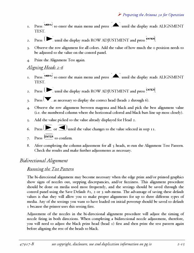
Row Adjustment
Use row adjustment to horizontally align print heads 2-6 with print head 1 (black). If there is adifference of more than six pixels between all five colors, you will have to increase your swathadjustment and reprint the test pattern. In this alignment, you can only adjust between two andeight pixels.
Aligning Head 1
NOTE Black should only be changed if the 0 position needs to be changed. If thisisn’t necessary, proceed with aligning heads 2-6.
� Preparing the Arizona 30 for Operation
47917-B see copyright, disclosure, use and duplication information on pg iv 2-15
1. Press to enter the main menu and press until the display reads ALIGNMENTTEST.
2. Press until the display reads ROW ADJUSTMENT and press .
3. Observe the row alignment for all colors. Add the value of how much the 0 position needs tobe adjusted to the value on the control panel.
4. Print the Alignment Test again.
Aligning Heads 2-6
1. Press to enter the main menu and press until the display reads ALIGNMENTTEST.
2. Press until the display reads ROW ADJUSTMENT and press .
3. Press as necessary to display the correct head (heads 2 through 6).
4. Observe the row alignment between magenta and black and pick the best alignment value(i.e. the numbered column where the horizontal colored and black bars line up most closely).
5. Add the value picked to the value already displayed for Head 2.
6. Press or until the value changes to the value selected in step 11.
7. Press to confirm.
8. After completing the column adjustment for all 5 heads, re-run the Alignment Test Pattern.Check the results and make further adjustments as necessary.
Bidirectional Alignment
Running the Test Pattern
The bi-directional alignment may become necessary when the edge print and/or printed graphicsshow signs of nozzles out, stepping discrepancies, and/or fuzziness. This alignment procedureshould be done on media used most frequently, and the settings should be saved through thecontrol panel using the Save Default #1, 2 or 3 sub-menu. The advantage of saving these defaultvalues is that they will allow you to make proper alignments for up to three different types ofmedia. Any of the settings you want to have loaded on initial powerup should be saved to default1 because the printer uses this setting first.
Adjustment of the nozzles in the bi-directional alignment procedure will adjust the timing ofnozzle firing in both directions. When completing a bidirectional nozzle adjustment, therefore,you will need to adjust the black print head (head 1) first and then print the test pattern againbefore aligning the rest of the heads to black.

Arizona 30 Sign Printer User Guide �
see copyright, disclosure, use and duplication information on pg iv 47917-B2-16
1. Load the Arizona 30 with paper.
2. Press MENU on the keypad to enter the menu functions.
3. Press until the display reads ALIGN HEADS TEST.
4. Press until the display reads BI-DIRECTION TEST.
5. Press to run the alignment test shown below.
Figure 2-17 Bi-directional Alignment Test Pattern
Aligning the heads
1. Adjust black first, which is the first row of lines from –12 to 12. Look for the straightest pairof lines within the row. If none of the pairs line up, then select the line closest to straight orvertical (either –12 or 12).
2. Add the value shown above the vertical line into the control panel sub-menu for black. Forexample, if the control panel reads 35 and the number you selected from the media is –7,
then use the key to decrease the value to 28. In another example, if the control panel
reads 35 and the number you selected from the media is 3, then use the key to increasethe value to 38. If the control panel reads -3 and you selected -7, then the end result wouldbe -10.
NOTE Values entered in the Bi-dir Adj sub-menu must be between -60 and 60.
3. Print the Bi-directional Alignment test pattern again. The black print head alignment mustbe perfect before moving on to the remaining five heads to be aligned.
4. Adjust print heads 2 through 6 using the same method mentioned above.

� Preparing the Arizona 30 for Operation
47917-B see copyright, disclosure, use and duplication information on pg iv 2-17
5. Immediately save the values to the desired default setting (1, 2 or 3). In this case, save it toDefault #1 through the control panel “Save Default” menu. You can later load a differentdefault setting for a particular media for which the Bi-directional Alignment was previouslysetup.
6. It is recommended that you write down all the values (Bi-directional alignment, RowAdjustment, Column Adjustment and Swath Adjustment) saved in Default 1, 2 and 3, sothat you have a permanent record.
7. Your Arizona 30 is now ready for printing.
Width Adjustment
The width adjustment is required when adjusting the carriage servo motor encoder. Thisadjustment will allow you to adjust the printing width along the carriage direction by increasingor decreasing the carriage speed in encoder counts (0.0027” or 0.070 mm). Fifteen encodercounts is equivalent to one drop of ink, so changing one number digit on the control panel underthe Width Adj. sub-menu is equivalent to a change of 1/15th of a drop.
1. In production software, create a solid black box 2” high x 48” wide and print the test box,using black ink only.
2. After printing, measure the width of the box with a one-meter ruler or equivalent.
3. If the box is longer than 48 inches on the media, you’ll need to increase the encoder count. Ifthe box is shorter than 48 inches on the media, you’ll need to decrease the encoder count.
4. At the Width Adj.: XX enc., add to or subtract from the value that is already in the machine.Use the following menu functions to input your value:
� Press to decrease adjustment.
� Press to increase adjustment.
� Press to set the selected value. Returns an OK prompt when set.
� Press to go to the previous menu.
� Press to exit this menu and return to printing mode.
End of Section

Arizona 30 Sign Printer User Guide �
see copyright, disclosure, use and duplication information on pg iv 47917-B2-18
THIS PAGE INTENTIONALLY LEFT BLANK
� Using the Control Panel
47917-B see copyright, disclosure, use and duplication information on pg iv 3-1
3 Using the Control Panel
Control Panel Functions
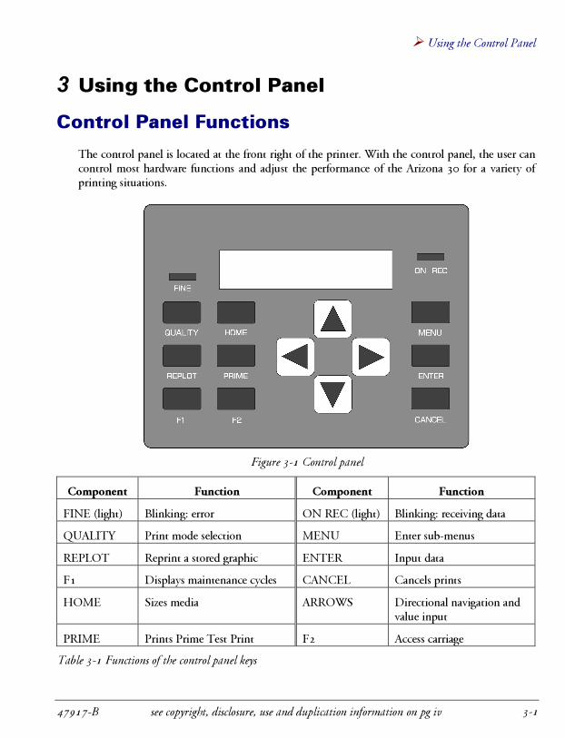
The control panel is located at the front right of the printer. With the control panel, the user cancontrol most hardware functions and adjust the performance of the Arizona 30 for a variety ofprinting situations.
Figure 3-1 Control panel
Component Function Component Function
FINE (light) Blinking: error ON REC (light) Blinking: receiving data
QUALITY Print mode selection MENU Enter sub-menus
REPLOT Reprint a stored graphic ENTER Input data
F1 Displays maintenance cycles CANCEL Cancels prints
HOME Sizes media ARROWS Directional navigation andvalue input
PRIME Prints Prime Test Print F2 Access carriage
Table 3-1 Functions of the control panel keys

Arizona 30 Sign Printer User Guide �
see copyright, disclosure, use and duplication information on pg iv 47917-B3-2
Navigating the Menus
Press to access the main menu pages, which are laid out serially. When you want to leave
the menu pages, the key will return you to print mode. Advance from page to page with
the and arrow keys. While you are in any of the main menu pages, you can change
settings, toggle values or select submenus using the and keys. The key is
generally used to accept changes you have made. In most cases, an OK prompt will be returned
when the values are set. In some cases, you must press and choose YES to enter a sub-
menu. Each of the menu pages is explained below, including factory default settings where
relevant. Where navigation differs from the procedures described above, detailed instructions are
included. The printer settings at power up will be determined by the values saved to Default #1
(see “Save Default” and “Load Default” for more details on user-assigned defaults).

� Using the Control Panel
47917-B see copyright, disclosure, use and duplication information on pg iv 3-3
Width = 00.00 in
Length = 999.99 in
Set Origin: 1.0 in
< > Enter
Print Quality: 1 Pass
< > Enter
Number of Pass: 1
< > Enter
Print Mode: Uni
< > Enter
Replot: 1
< > Enter
Load Default: 1
< > Enter
Save Default: 1
< > Enter
Dry Time: 00 min.
< > Enter
Park Time: 05 sec.
< > Enter
Swath Delay: 00 sec.
< > Enter
Serial Port: No
< > Enter
External Command: No
< > Enter
Adj Saturation: No
< > Enter
Flush Buffer: No
< > Enter
Display Unit: Inch
< > Enter
Print Quality: 2 Pass
< > Enter
Print Quality: 4 Pass
< > Enter
Print Quality: 8 Pass
< > Enter
Print Mode: Bi
< > Enter
Edge Print: R-Full
< > Enter
Edge Print: R-Half
< > Enter
Edge Print: L-Full
< > Enter
Edge Print: L-Half
< > Enter
External Command: Yes
< > Enter
Serial Port: Y es
< > Enter
Adj Saturation: Yes
< > Enter
Align Heads: Test
< > Enter
Align Heads: Column
< > Enter
Align Heads: Row
< > Enter
Align Heads: Bi-dir
< > Enter
Align Heads: Width
< > Enter
Align Heads: Swath
< > Enter
Align Heads: X-Back
< > Enter
Flush Buffer: Yes
< > Enter
Load Default: 2
< > Enter
Load Default: 3
< > Enter
Save Default: 2
< > Enter
Save Default: 3
< > Enter
2a 2b 2c 2d 2e 2f 2g
3
Edge Print: Off
< > Enter
Edge Distance: 0.2in
< > Enter
Advance Dist: 2.2in
< > Enter
Figure 3-2 Menu Flow Chart (1 of 2)

Arizona 30 Sign Printer User Guide �
see copyright, disclosure, use and duplication information on pg iv 47917-B3-4
Soft Cleaning
< > Enter
Head 2: 00 pixels
< > Enter
Head 3: 00 pixels
< > Enter
Head 4: 00 pixels
< > Enter
Head 5: 00 pixels
< > Enter
Head 6: 00 pixels
< > Enter
Head 1: 00 pixels
< > Enter
Drop Size Hd 1: 50
< > Enter
Hard Cleaning
< > Enter
Ink Clearing
< > Enter
Ink Priming
< > Enter
Adj Saturation: Yes
< > Enter
Head Flushing
< > Enter
Align Heads: Test
< > Enter
Alignment Test
< > Enter
Prime Test
< > Enter
Bi-direction Test
< > Enter
Burn-in Self Test
< > Enter
2a
Align Heads: Column
< > Enter
Align Heads: Row
< > Enter
Align Heads: Bi-dir
< > Enter
Align Heads: Width
< > Enter
Align Heads: Swath
< > Enter
Align Heads: X-Back
< > Enter
2b 2c 2d 2e 2f 2g
Bi-dir Adj: 00 pixels
< > Enter
Width Adj: 00 enc
< > Enter
Head 2: 00 pixels
< > Enter
Head 3: 00 pixels
< > Enter
Head 4: 00 pixels
< > Enter
Head 5: 00 pixels
< > Enter
Head 6: 00 pixels
< > Enter
Head 2: 00 pixels
< > Enter
Head 3: 00 pixels
< > Enter
Head 4: 00 pixels
< > Enter
Head 5: 00 pixels
< > Enter
Head 6: 00 pixels
< > Enter
Swath Adj: 00 enc
< > Enter
X Backlash: 00 enc
< > Enter
3
Drop Size Hd 2: 50
< > Enter
Drop Size Hd 3: 50
< > Enter
Drop Size Hd 4: 50
< > Enter
Drop Size Hd 5: 50
< > Enter
Drop Size Hd 6: 50
< > Enter
Figure 3-3 Menu Flow Chart (2 of 2)

� Using the Control Panel
47917-B see copyright, disclosure, use and duplication information on pg iv 3-5
Material Width and Length
Width = 00.00 in
Length = 999.99 in
This page displays (in the currently selected units) the width and length of the media as measuredduring the homing process.
Set Origin
Set Origin: 1.0 in
< > Enter
The Arizona 30 uses a plot relative origin, meaning that there is no fixed origin. The are two waysthe printer can determine the origin (where the printer will start printing). Using the automaticorigin, the printer will start to print at the right side of the media. Alternatively, this page willallow you to choose where the printer will begin to print by adding a specific distance from theright edge of the media. If you choose to manually position the head carriage using the arrowkeys, any value entered in this page will be ignored.
Print Quality
Print Quality: 2 Pass
< > Enter
This page allows you to change print quality by setting the number of interleave passes per printswath. There are 1-pass, 2-pass, 4-pass, and 8-pass modes. As the number of passes increases, theprint quality improves, and the swath height and the overall speed decrease. Alternatively, you
can use the QUALITY key to enter this menu from Jogging mode.

Arizona 30 Sign Printer User Guide �
see copyright, disclosure, use and duplication information on pg iv 47917-B3-6
Number of Passes
Number of Pass: 1
< > Enter
This menu allows you to set the number of times to overprint each swath, therefore increasing ordecreasing the volume of ink laid down. You can select 1 to 10 passes; the factory default is 1.When you use this function, the printer will automatically switch back to unidirectional printmode. Note that too many passes could over-saturate the media with ink.
Print Direction
Print Mode: Bi
< > Enter
This page allows you to switch between unidirectional and bidirectional printing modes.Bidirectional mode results in faster overall print speed and is the factory default.
Re-plot
Replot: 1
< > Enter
This page allows you to reprint an image multiple times from the printer’s RAM buffer. You may
also use the REPLOT key to enter this menu from Jogging mode. Use the keypad to select thenumber of copies you wish to reprint (0-99, factory default is 1). If there is no image in RAM,the printer will return a JOB QUEUE: EMPTY error message. If the image printed earlier doesnot fit into RAM, the printer will return an IMAGE TOO LARGE error message. If a Dry Timeis set, the printer will wait between reprints for that specified period.

� Using the Control Panel
47917-B see copyright, disclosure, use and duplication information on pg iv 3-7
Load Default
Load Default: 1
< > Enter
This page allows you to load default printer settings from 4 previously saved selections. Printersettings may be changed and saved to default settings 1-3 in the Save Default page. Default setting0 contains the factory defaults. Default setting 1 is automatically loaded at power up, so anysettings you want the printer to default to at power up should be saved to Default 1.
Save Default
Save Default: 1
< > Enter
This page allows you to save printer settings to default settings 1-3. Printer settings may be loadedfrom default settings 1-3 by using the Load Default menu. Default setting 1 is automaticallyloaded at power up, so any settings you want the printer to default to at power up should savedinto Default 1.
The following settings can be saved in each default:� Set Origin� Print Mode� Number of Passes� Print Mode� Dry Time� Park Time� Swath Delay� Edge Distance� Edge Print� Set Serial Port� External Command� Bidirectional Adjustments� Advance Distance

Arizona 30 Sign Printer User Guide �
see copyright, disclosure, use and duplication information on pg iv 47917-B3-8
Dry Time
Dry Time: 00 min.
< > Enter
This page allows you to set the time that the Arizona 30 waits between print jobs (in minutes).You may select from 0 to 546 minutes; the factory default is 0 minutes (no dry time). Anappropriate dry time allows the printed image to dry before the printer starts the next image, thuspreventing smudging of damp ink on the uptake roll. The suitable dry time will depend onfactors such as ambient temperature and humidity, the media used, ink saturation and number ofpasses performed settings. You may need to experiment to find the optimal dry time setting foryour print jobs.
This menu may be accessed when the printer is idle, as well as during printing. When a dry timeis in use, the printer will display a countdown timer after each image has finished printing. Newjobs can be sent to the printer while the countdown is on, but they will not begin printing until ithas reached zero. This applies to both new jobs sent to the printer and re-plotted jobs. If multiplere-plots are selected, dry time will be in effect after each print. The dry time countdown can becancelled by pressing the CANCEL key.
Park Time
Park Time: 05 sec.
< > Enter
The park time is the time that the carriage can be out of the maintenance station, but idle, beforeit is automatically returned to the maintenance station. This page allows you to set the Arizona30’s park time in seconds. This menu may be accessed when the printer is idle, as well as duringprinting. The default setting is 5 seconds and should not be changed, except on the advice of anauthorized field engineer or a factory representative.
Swath Delay
Swath Delay: 00 sec.
< > Enter

� Using the Control Panel
47917-B see copyright, disclosure, use and duplication information on pg iv 3-9
The swath delay is the pause (in seconds) between printing swaths. Use this function when theink and media need extra time to bond. This menu may be accessed when the printer is idle, aswell as during printing.
Edge Distance
Edge Distance: 0.2in
< > Enter
The edge distance is the distance of the color bar from the right edge of the media. This menumay only be accessed when the printer is idle.
Edge Print
Edge Print: R-Full
< > Enter
An edge print is a color bar printed at the right or left edge of the image. This page allows you toturn the edge print operation on and off, and select from 4 different types of edge prints. An edgeprint is recommended when using inks with high resin contents. This menu page may only beaccessed when the printer is idle.
Set Serial Port
Serial Port: No
< > Enter
Use this page to enter the Serial Port Protocol submenu - select YES and press . From thesubmenu, you can change the baud rate, stop bits, data bits, parity and handshaking of theprinter’s serial port to match your computer’s serial port settings and software’s communicationprotocol.
Serial Baud Rate
This page allows you to change the baud rate of the printer’s serial port. The choices are 9600 or19200; the factory default is 9600.

Arizona 30 Sign Printer User Guide �
see copyright, disclosure, use and duplication information on pg iv 47917-B3-10
Serial Stop Bits
This page allows you to change the stop bit setting of the printer’s serial port. The choices are 1or 2; the factory default is 2.
Serial Data Bits
This page allows you to change the data bit setting of the printer’s serial port. The choices are 7or 8; the factory default is 8.
Parity
This page allows you to change the parity setting of the printer’s serial port. The choices areNone, Even or Odd; the factory default is None.
Serial Hand Shaking
This page allows you to change the handshaking setting of the printer’s serial port. The choicesare Hardware or Xon/Xoff (software handshaking); the factory default is Hardware.
External Command
External Command: Yes
< > Enter
This page allows you to override the print mode selected by the software, or ignore the softwarecommand. When the External Command mode is set to YES, the printer will accept the softwarecommand and change to the print mode that the software specifies (if software control isavailable). When set to NO, the printer will ignore the external software command and print inthe mode that is selected by the user (Print Mode page). Files ripped and printed with a specificprint mode can be re-plotted in another print mode by changing the option to NO and then re-plotting.
Align Heads
This page allows you to access the alignment test, column alignment, row alignment,bidirectional alignment, width alignment, swath adjustment and x-backlash adjustment menus.Upon completion of printing any of the test patterns, the printer will return to this menu page.
Align Heads: Test
< > Enter

� Using the Control Panel
47917-B see copyright, disclosure, use and duplication information on pg iv 3-11
Align Heads: Column
< > Enter
Align Heads: Row
< > Enter
Align Heads: Bi-dir
< > Enter
Align Heads: Width
< > Enter
Align Heads: Swath
< > Enter
Align Heads: X-Back
< > Enter
The alignment test pattern consists of three parts—the color bands for each print head, thehorizontal alignment chart for each head (column), and the vertical alignment chart for each head(row). You will need to print this test pattern to aid you in aligning the Arizona 30’s heads. Thebidirectional test pattern is similar the first two sections of the alignment test pattern.
Properly aligned heads will show all color bands to be even with no gaps between them, and thecolumn, row and bidirectional charts will line up on 0 (zero) for each color.
Alignment Test
Alignment Test
< > Enter

Arizona 30 Sign Printer User Guide �
see copyright, disclosure, use and duplication information on pg iv 47917-B3-12
This page is the first of four test pattern pages. The available test patterns are Alignment Test,Prime Test, Bidirectional Test, and Burn-in Self-Test.
Column Alignment
This page allows you to enter the Column Alignment sub-menu. From there, you can adjust andset the head alignment horizontally for all of the print heads relative to each other. Use theColumn Alignment grid printed by the Align Head: Test > Alignment Test menu to determinehow to fine-tune these adjustments.
Heads 2-6
Head 2: 00 pixels
< > Enter
This sub-menu allows you to adjust each head in pixels (0.0027 in, or 0.070 mm) so that all thehead’s color lines match up with the black line on the column grid marked 0 (zero).
Row Alignment
This menu allows you to enter the Row Alignment sub-menu. From there, you can adjust and setthe head alignment vertically for all of the print heads relative to each other. Use the RowAdjustment grid printed by the Align Head: Test > Alignment Test menu to determine how tofine-tune these adjustments.
Heads 1-6
Head 1: 00 pixels
< > Enter
This sub-menu allows you to adjust each head in pixels (0.0027 in, or 0.070 mm) so that all thehead’s color lines match up with the black line on the column grid marked 0 (zero).
Bidirectional Alignment
Bi-dir Adj: 00 pixels
< > Enter

� Using the Control Panel
47917-B see copyright, disclosure, use and duplication information on pg iv 3-13
This menu allows you to change from unidirectional to bidirectional printing. Run thebidirectional test pattern under the alignment test sub-menu before selecting this option.
This sub-menu allows you to adjust offset for printing in bidirectional mode for all heads inencoder counts (0.0002 in, or 0.005 mm). Set this value after printing the bidirectional testpatterns.
Heads 2-6
Head 2: 00 pixels
< > Enter
This sub-menu allows you to adjust the offset for printing in bidirectional mode for individualheads 2-6 in pixels (0.0027 in, or 0.070 mm). Set this value after printing the bidirectional testpatterns.
Width Alignment
Width Adj: 00 enc
< > Enter
This menu allows you to adjust the printing width.
This sub-menu allows you to adjust the printing width along the carriage direction by increasingor decreasing the carriage speed in encoder counts (0.0027 in, or 0.070 mm).
Swath Adjustment
Swath Adj: 00 enc
< > Enter
This menu allows you to adjust the printing swath in encoder counts (0.0002 in, or 0.005 mm).Setting this value, can affect the ability of the row alignment functions to come into alignment.Usually, the values should not go higher or lower than �5 increments.
This sub-menu allows you to adjust and set the swath separation value in encoder counts (0.0027in, or 0.070 mm) so that each color swath prints out without gaps or overlaps.

Arizona 30 Sign Printer User Guide �
see copyright, disclosure, use and duplication information on pg iv 47917-B3-14
Backlash Adjustment
X Backlash: 00 enc
< > Enter
This menu allows you to enter the X-Backlash alignment sub-menu. From there, you can adjustand set the backlash value for the X-axis drive belt, which controls the material advance. Thisvalue will be preset at our factory and should only need to be changed if the X-axis belt isreplaced. Usually, the value is between 5 and 10.
This sub-menu allows you to adjust and set the X-Backlash value in encoder counts (0.0027 in,or 0.070 mm) for the X-axis drive belt. This value will compensate for stretch or tension in the X-axis drive belt.
Saturation Adjustment
Adj Saturation: No
< > Enter
This menu allows you to control the size of each ink droplet jetted by each of the six print heads.Setting this menu to YES causes it to branch to the Drop Size sub-menu, allowing you to changethe size of the ink droplets for each head independently.
Heads 1-6
Drop Size Hd 1: 50
< > Enter
This sub-menu allows you to uniformly set the drop size for all the nozzles on each head from 1to 6. The range on this setting is specific for each head. These values should only be changedwhen requested by an authorized field engineer or a factory representative. If you change thesevalues, printing quality can’t be guaranteed, and severe damage will be caused to the print head.

� Using the Control Panel
47917-B see copyright, disclosure, use and duplication information on pg iv 3-15
Flush Buffer
Flush Buffer: No
< > Enter
This menu allows you to empty the buffer of all data.
Display Units
Display Unit: Inch
< > Enter
This menu allows you to change the printer display units to inches or centimeters.
Advance Distance
Advance Dist: 2.2in
< > Enter
This menu allows you to change the margin between each print (on the X axis), when it is nototherwise controlled by the software.
Using the F1 Cleaning Menu
The F1 key gives you access to five cleaning cycles: Soft Cleaning, Hard Cleaning, Ink Clearing,Ink Priming, and Head Flushing.
Soft Cleaning
< > Enter

Arizona 30 Sign Printer User Guide �
see copyright, disclosure, use and duplication information on pg iv 47917-B3-16
Hard Cleaning
< > Enter
Ink Clearing
< > Enter
Ink Priming
< > Enter
Head Flushing
< > Enter
- select the previous cleaning cycle.
- select the next cleaning cycle.
- begin the cleaning cycle
Soft Cleaning
This is the cleaning operation you will use most often. Use this method if air bubbles in the printhead are causing misprinting of the nozzles. Use this method if nozzles are temporarily notprinting or if nozzles are firing weakly or crooked. The printer will also perform this cleaningcycle before every print job.
1. Press F1 and verify that the display reads SOFT CLEAN.
2. Press to initiate the cleaning cycle.
Hard Cleaning
Use this method when soft cleaning fails to unclog clogged nozzles.

� Using the Control Panel
47917-B see copyright, disclosure, use and duplication information on pg iv 3-17
1. Press F1 to display the maintenance cycles.
2. Press once to display HARD CLEANING.
3. Press to initiate the cleaning cycle.
Ink Clearing
Use this method to clear the maintenance station of residual ink.
1. Press F1 to display the maintenance cycles.
2. Press twice to display INK CLEARING.
3. Press to initiate the cycle.
4. This cycle will continue until the operator presses the CANCEL key.
Ink Priming
Use this to load the system with ink. See the section “Priming the System with Ink.”
1. Press F1 to display the maintenance cycles.
2. Press three (3) times to display INK CLEARING.
3. Press to initiate the cycle.
4. This cycle will continue until the operator presses CANCEL.
Head Flushing
1. Press F1 to display the maintenance cycles.
2. Press four (4) times to display HEAD FLUSHING.
3. Press to initiate the cycle.
4. Press CANCEL to stop and complete the cycle.
Cleaning the Maintenance Station
1. Open the maintenance station access hatch.
2. Press F2 to move the carriage out of the maintenance station.
3. Press to make sure the ink in the caps will drain.

Arizona 30 Sign Printer User Guide �
see copyright, disclosure, use and duplication information on pg iv 47917-B3-18
4. While pressing , carefully squirt 3M CGS-80 solvent into the caps to clean out themaintenance station and tubing going to the waste tank.
NOTE Performing step 4 will cause the waste tank to fill much faster than normalbecause of the extra solvent entering the system. To prevent overflow, payspecial attention to the level in the waste tank.
Printer Operating Modes
The Arizona 30 uses 3 print quality modes: 2-pass, 4-pass and 8-pass. These modes can beselected by pressing the QUALITY key on the control panel (see “”)
2-Pass Mode
At 30 square feet an hour (360 dpi), the bi-directional, two-pass mode is the fastest mode. Forquick printouts or drafts, this is the mode to use.
4-Pass Mode
At up to 18 square feet an hour (360 dpi), the bi-directional, four-pass mode is used for standardprinting of single or multiple job runs and should be used in conjunction with the take-up core.
8-Pass Mode
Up to 9 square feet an hour (360 dpi), the bi-directional, eight-pass mode is used to produce thebest quality prints from the Arizona 30.
Error Codes
When error messages 1 to 27 are displayed, the printer will shut down. Pressing the CANCEL keywill cause the printer to restart as if power were turned off and back on.
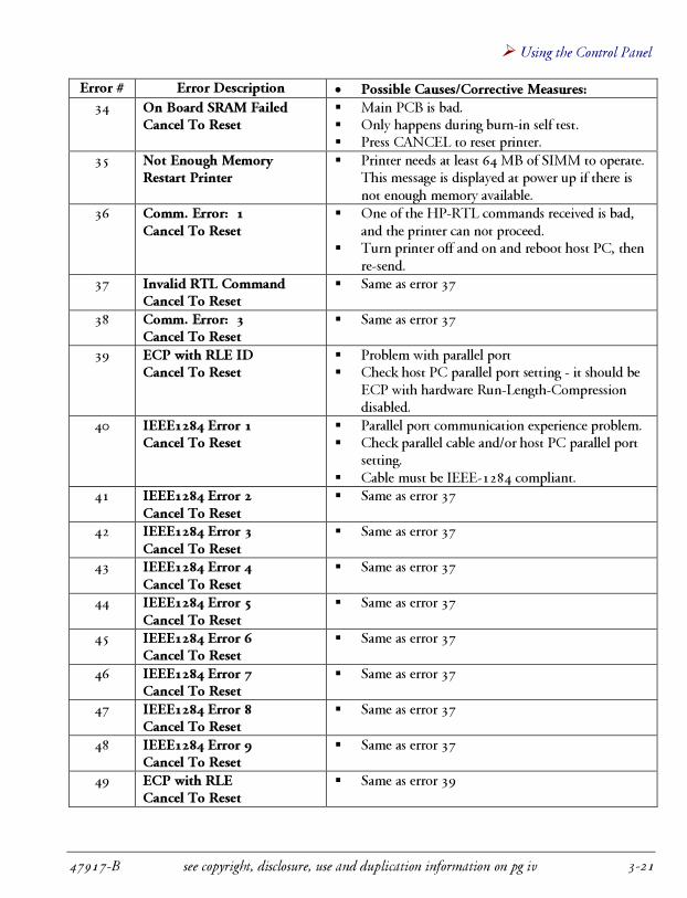
When error messages 30 to 52 are displayed, printer needs to be powered down. Check the printerand/or take corrective measures before turning the printer back on. These errors are mainly used fordevelopment and trouble-shooting and should not displayed under normal operation.
When error messages 60 to 65 are displayed, simply press the CANCEL or ENTER key to resumenormal operation. Be sure to perform corrective actions.
Error # Error Description � Possible Causes/Corrective Measures:
1 Divided By ZeroCancel To Reset
� Printer internal problem� Main PCB may be bad� Press CANCEL to reset printer

� Using the Control Panel
47917-B see copyright, disclosure, use and duplication information on pg iv 3-19
Error # Error Description � Possible Causes/Corrective Measures:
2 Debug ExceptionCancel To Reset
� Same as error 1
3 NMI InterruptCancel To Reset
� Same as error 1
4 One Byte InterruptCancel To Reset
� Same as error 1
5 Overflow InterruptCancel To Reset
� Same as error 1
6 Bounce ErrorCancel To Reset
� Same as error 1
7 Invalid Opcode Cancel ToReset
� Same as error 1
8 Device Not AvailableCancel To Reset
� Same as error 1
9 Double FaultCancel To Reset
� Same as error 1
10 Intel Reserved IntCancel To Reset
� Same as error 1
11 Invalid TSSCancel To Reset
� Same as error 1
12 Segment Not Present CancelTo Reset
� Same as error 1
13 Stack FaultCancel To Reset
� Same as error 1
14 General Protection CancelTo Reset
� Same as error 1
15 Page FaultCancel To Reset
� Same as error 1
16 Floating Point ErrorCancel To Reset
� Same as error 1
17 Alignment CheckCancel To Reset
� Same as error 1
18 Maskable Int. #2Cancel To Reset
� Same as error 1
19 Maskable Int. #3Cancel To Reset
� Same as error 1
20 Maskable Int. #4Cancel To Reset
� Same as error 1
21 Maskable Int. #5Cancel To Reset
� Same as error 1

Arizona 30 Sign Printer User Guide �
see copyright, disclosure, use and duplication information on pg iv 47917-B3-20
Error # Error Description � Possible Causes/Corrective Measures:
22 Unknown Key StateCancel To Reset
� Same as error 1
23 Invalid State Detect CancelTo Reset
� Same as error 1
24 X-Axis OverloadedCancel To Reset
� Problem with 39.5 VDC supply to the motor.� The X-motor connector leads are loose at both the
PCB and motor ends.� Encoder cable is either loose or wrong.� The media movement is stuck, or the media roll is
hard to pull.� The motor is bad.� The amplifying circuit on main PCB is bad.
25 Y-Axis Overloaded CancelTo Reset
� Same as Error 24, but Y-motor affected (headcarriage movement mechanism).
26 Homing errorCancel To Reset
� Printer has encountered a problem during thehoming cycle.
� Normally occurs when the printer cannot movethe head carriage back and forth for the full lengthof the platen.
27 FIFO Local Failed CancelTo Reset
� Printer internal problem� Print Controller PCB might be bad.� Press CANCEL to reset printer.
30 Shutdown Error: 15 CancelTo Reset
� Same as error 1
31 FIFO Serial Failed CancelTo Reset
� Printer internal problem� One or more heads might be bad.� One or more head ribbon cables might be bad.� The flex cable might be bad.� Print Controller PCB and/or head controller PCB
might be bad.� Press CANCEL to reset printer.
32 FIFO Local Test FailedCancel To Reset
� Same as error 27� Only happens during burn-in self test.� Press CANCEL to reset printer.
33 SIMM Test Failed Cancel ToReset
� One or more SIMMs (Single In-line MemoryModule) is bad.
� Main PCB is bad.� Only happens during burn-in self test.� Press CANCEL to reset printer.
� Using the Control Panel
47917-B see copyright, disclosure, use and duplication information on pg iv 3-21
Error # Error Description � Possible Causes/Corrective Measures:
34 On Board SRAM FailedCancel To Reset
� Main PCB is bad.� Only happens during burn-in self test.� Press CANCEL to reset printer.
35 Not Enough MemoryRestart Printer
� Printer needs at least 64 MB of SIMM to operate.This message is displayed at power up if there isnot enough memory available.
36 Comm. Error: 1Cancel To Reset
� One of the HP-RTL commands received is bad,and the printer can not proceed.
� Turn printer off and on and reboot host PC, thenre-send.
37 Invalid RTL CommandCancel To Reset
� Same as error 37
38 Comm. Error: 3Cancel To Reset
� Same as error 37
39 ECP with RLE IDCancel To Reset
� Problem with parallel port� Check host PC parallel port setting - it should be
ECP with hardware Run-Length-Compressiondisabled.
40 IEEE1284 Error 1Cancel To Reset
� Parallel port communication experience problem.� Check parallel cable and/or host PC parallel port
setting.� Cable must be IEEE-1284 compliant.
41 IEEE1284 Error 2Cancel To Reset
� Same as error 37
42 IEEE1284 Error 3Cancel To Reset
� Same as error 37
43 IEEE1284 Error 4Cancel To Reset
� Same as error 37
44 IEEE1284 Error 5Cancel To Reset
� Same as error 37
45 IEEE1284 Error 6Cancel To Reset
� Same as error 37
46 IEEE1284 Error 7Cancel To Reset
� Same as error 37
47 IEEE1284 Error 8Cancel To Reset
� Same as error 37
48 IEEE1284 Error 9Cancel To Reset
� Same as error 37
49 ECP with RLECancel To Reset
� Same as error 39

Arizona 30 Sign Printer User Guide �
see copyright, disclosure, use and duplication information on pg iv 47917-B3-22
Error # Error Description � Possible Causes/Corrective Measures:
50 Processing ErrorCancel To Restart
� Probable unreliable communication from the hostPC to the printer.
� Reboot both the computer and the printer, thenretest.
� Use a shorter IEEE-1284 certified parallel cableand retest.
� Remove security key from PC, then send an imageusing Job Controller.
� Reboot the computer, set parallel communicationto EPP mode and retest.
� If all of the above steps fail, there may besomething wrong with the main PCB.
51 Print Controller FailCancel To Restart
� Probable unreliable communications from printcontroller PCB to header PCB and/or header PCBto head connector PCB.
� There might also be one or more bad print heads,and/or the print controller PCB is defective.
� Check the flex cable and ribbon cable.52 System Test
Head 1 Voltage: Fail
System TestHead 2 Voltage: Fail
System TestHead 3 Voltage: Fail
System TestHead 4 Voltage: Fail
System TestHead 5 Voltage: Fail
System TestHead 6 Voltage: Fail
� One or more of the six power-supply circuits (onefor each print head) has failed the power checkingsequence. When one of the six circuits fails, all ofthe six circuits are cut off.
� Check flex cable, header PCB, heads, ribboncable.
� Print controller PCB might be bad.

� Using the Control Panel
47917-B see copyright, disclosure, use and duplication information on pg iv 3-23
Error # Error Description � Possible Causes/Corrective Measures:
60 Image Error # 2Cancel To Restart
� The left edge of the image sent from the computeris falling outside the available media.
� Possible causes include user error or faulty media-sensing devices.
� Check the image size and the media width fromLCD display, as well as the starting point of printhead carriage.
� If they are all OK, re-home the printer on blank,clean media and check the media width on theLCD.
� If the media width is incorrect, it is likely that themedia-sensing devices are not working properly.Checking and adjusting or replacing the mediasensor can solve this problem.
61 Image Error # 3Cancel To Restart
� Same as Error 58, but affecting right edge ofmedia instead.
62 Image Error # 1Cancel To Restart
� The left edge of the media is falling outside thephysical limits of printer.
63 Lower CoverCancel To Reset
� One or both of the covers is open� Cover sensors might be defective� Check and close both covers and press CANCEL
64 Job Queue: EmptyEnter
� Re-plotting from keypad while there is no job inprinter buffer.
� Press ENTER, then send a job from the host PC.65 Job Queue: Large
Enter� Re-plotting from keypad while current job is too
large to fit into printer buffer.� Press ENTER, then send a job from the host PC.
The amount of memory in the printer willdetermine how large a job can be re-plotted.
End of Section

Arizona 30 Sign Printer User Guide �
see copyright, disclosure, use and duplication information on pg iv 47917-B3-24
THIS PAGE INTENTIONALLY LEFT BLANK


![Océ User manual - files.oceusa.comfiles.oceusa.com/.../TDS700/Documentation/OceTDS700_SafetyManual.pdf · 9 Doporučené hmotnostní limity [2] V následujícím přehledu jsou uvedeny](https://img.dokumen.tips/doc/110x75/5bf2484409d3f23f5f8cc12a/oce-user-manual-files-9-doporucene-hmotnostni-limity-2-v-nasledujicim.jpg)