Embed Size (px)
Citation preview
ABSOLUTE ROTARY ENCODER
MODBUS/TCP
Rev. 1.6 1. March - 2016 Scancon Huginsvej 8 3400 Hillerød Denmark p. 1 Tlf +45 48 17 27 02 Fax +45 48 17 22 84 www.scancon.dk
User Manual

ABSOLUTE ROTARY ENCODER
MODBUS/TCP
Rev. 1.6 1. March - 2016 Scancon Huginsvej 8 3400 Hillerød Denmark p. 2 Tlf +45 48 17 27 02 Fax +45 48 17 22 84 www.scancon.dk
ABSOLUTE ROTARY ENCODER
MODBUS/TCP
Rev. 1.6 1. March - 2016 Scancon Huginsvej 8 3400 Hillerød Denmark p. 3 Tlf +45 48 17 27 02 Fax +45 48 17 22 84 www.scancon.dk
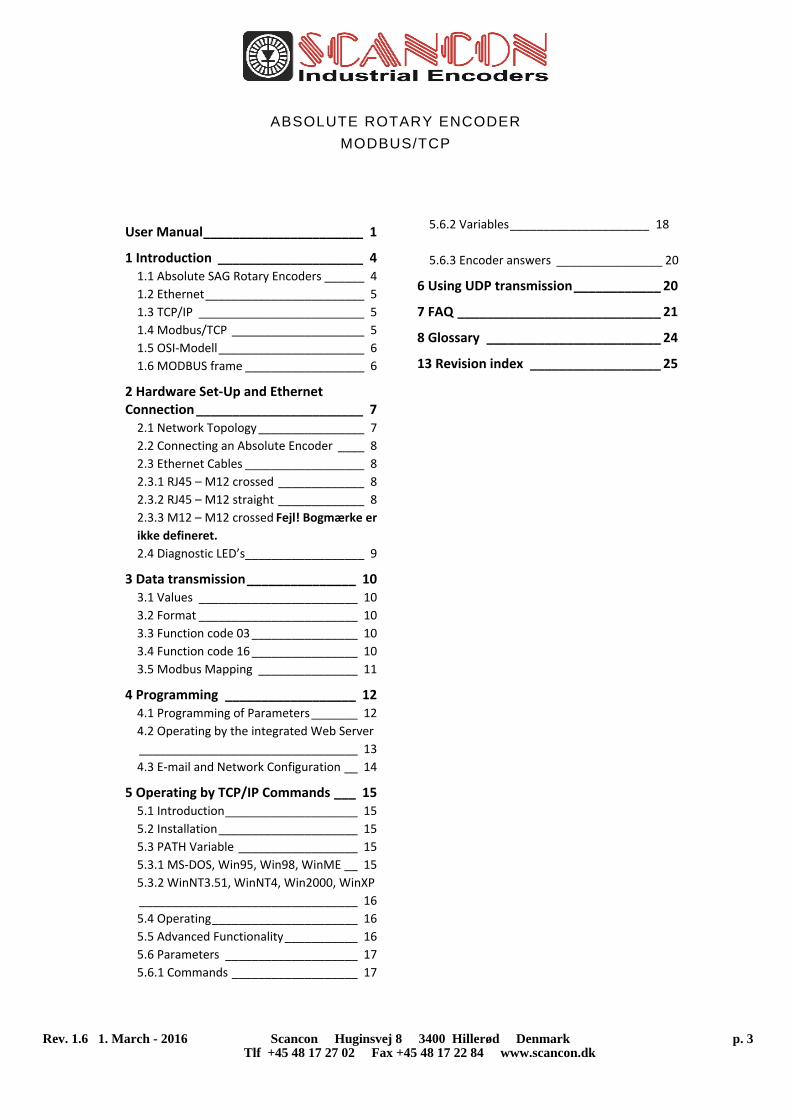
User Manual ______________________ 1
1 Introduction ____________________ 4 1.1 Absolute SAG Rotary Encoders ______ 4 1.2 Ethernet ________________________ 5 1.3 TCP/IP _________________________ 5 1.4 Modbus/TCP ____________________ 5 1.5 OSI‐Modell ______________________ 6 1.6 MODBUS frame __________________ 6
2 Hardware Set‐Up and Ethernet Connection _______________________ 7 2.1 Network Topology ________________ 7 2.2 Connecting an Absolute Encoder ____ 8 2.3 Ethernet Cables __________________ 8 2.3.1 RJ45 – M12 crossed _____________ 8 2.3.2 RJ45 – M12 straight _____________ 8 2.3.3 M12 – M12 crossed Fejl! Bogmærke er
ikke defineret. 2.4 Diagnostic LED’s __________________ 9
3 Data transmission _______________ 10 3.1 Values ________________________ 10 3.2 Format ________________________ 10 3.3 Function code 03 ________________ 10 3.4 Function code 16 ________________ 10 3.5 Modbus Mapping _______________ 11
4 Programming __________________ 12 4.1 Programming of Parameters _______ 12 4.2 Operating by the integrated Web Server
_________________________________ 13 4.3 E‐mail and Network Configuration __ 14
5 Operating by TCP/IP Commands ___ 15 5.1 Introduction ____________________ 15 5.2 Installation _____________________ 15 5.3 PATH Variable __________________ 15 5.3.1 MS‐DOS, Win95, Win98, WinME __ 15 5.3.2 WinNT3.51, WinNT4, Win2000, WinXP
_________________________________ 16 5.4 Operating ______________________ 16 5.5 Advanced Functionality ___________ 16 5.6 Parameters ____________________ 17 5.6.1 Commands ___________________ 17
5.6.2 Variables _____________________ 18
5.6.3 Encoder answers ________________ 20
6 Using UDP transmission ____________ 20
7 FAQ ____________________________ 21
8 Glossary ________________________ 24
13 Revision index __________________ 25
ABSOLUTE ROTARY ENCODER
MODBUS/TCP
Rev. 1.6 1. March - 2016 Scancon Huginsvej 8 3400 Hillerød Denmark p. 4 Tlf +45 48 17 27 02 Fax +45 48 17 22 84 www.scancon.dk
1 Introduction
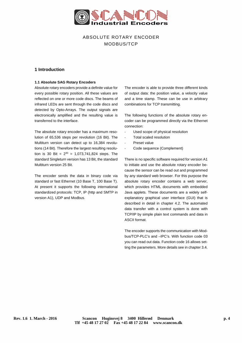
1.1 Absolute SAG Rotary Encoders
Absolute rotary encoders provide a definite value for
every possible rotary position. All these values are
reflected on one or more code discs. The beams of
infrared LEDs are sent through the code discs and
detected by Opto-Arrays. The output signals are
electronically amplified and the resulting value is
transferred to the interface.
The absolute rotary encoder has a maximum reso-
lution of 65,536 steps per revolution (16 Bit). The
Multiturn version can detect up to 16,384 revolu-
tions (14 Bit). Therefore the largest resulting resolu-
tion is 30 Bit = 230 = 1,073,741,824 steps. The
standard Singleturn version has 13 Bit, the standard
Multiturn version 25 Bit.
The encoder sends the data in binary code via
standard or fast Ethernet (10 Base T, 100 Base T).
At present it supports the following international
standardized protocols: TCP, IP (http and SMTP in
version A1), UDP and Modbus.
The encoder is able to provide three different kinds
of output data: the position value, a velocity value
and a time stamp. These can be use in arbitrary
combinations for TCP transmitting.
The following functions of the absolute rotary en-
coder can be programmed directly via the Ethernet
connection:
- Used scope of physical resolution
- Total scaled resolution
- Preset value
- Code sequence (Complement)
There is no specific software required for version A1
to initiate and use the absolute rotary encoder be-
cause the sensor can be read out and programmed
by any standard web browser. For this purpose the
absolute rotary encoder contains a web server,
which provides HTML documents with embedded
Java applets. These documents are a widely self-
explanatory graphical user interface (GUI) that is
described in detail in chapter 4.2. The automated
data transfer with a control system is done with
TCP/IP by simple plain text commands and data in
ASCII format.
The encoder supports the communication with Mod-
bus/TCP-PLC’s and –IPC’s. With function code 03
you can read out data. Function code 16 allows set-
ting the parameters. More details see in chapter 3.4.
ABSOLUTE ROTARY ENCODER
MODBUS/TCP
Rev. 1.6 1. March - 2016 Scancon Huginsvej 8 3400 Hillerød Denmark p. 5 Tlf +45 48 17 27 02 Fax +45 48 17 22 84 www.scancon.dk
1.2 Ethernet
The present developments in the field of Industrial
Ethernet are based on the vision of an integrated
access of all data of a company through a uniform
communication system. In higher levels of enter-
prise communication Ethernet is the main medium
of data transfers. Combined with other IT technolo-
gies it is internationally standardized. In the long run
automation engineers will benefit from the rapid
technological progress in the mass markets of IT
and web technologies.
Ethernet technically provides a system with higher
data transfer rates than common field bus systems.
TCP/IP and UDP do have a statistical access
method to access the medium thereby prohibiting
determined response times. Many developments
are intensely done on additional real time mecha-
nisms, e.g. Ethernet Powerlink, Ethernet/IP,
Profinet or EtherCAT. However, you can already get
access times that are sufficient for many applica-
tions when using TCP/IP or UDP. If you directly con-
nect the absolute encoder to a computer via a 100
Mbit network card, you will get a cycle time of less
than 2 ms. In huge networks the cycle times will de-
pend on the utilization of the network.
1.3 TCP/IP
Even though Ethernet and TCP/IP are often used
together and sometimes used interchanged, these
are three different kinds of terms and you should
carefully separate them. The coherences are based
on the ISO/OSI reference model after ISO/IEC 7498
that is needed to basically understand these terms.
Ethernet only describes layer 1 and 2 in this model,
nevertheless the term is often used in error in engi-
neering as description of all layers between 1 and 7.
The IP protocol of layer 3 was developed in the 70’s
by the US military (MIL-STD 1777). It allows a uni-
versal addressing independent of the hardware in-
volved in heterogeneous networks. It also manages
the transfer of large packets by splitting them up into
smaller packets. The well-known TCP protocol
(MIL-STD 1778) ensures a reliable data transfer.
Http (RFC 2068) and SMTP (MIL-STD 1781) belong
to layer 7 of the OSI model and allow to transfer data
and documents via web browser or to send e-mails.
1.4 Modbus/TCP
MODBUS is an application layer messaging proto-
col, positioned on level 7 of the OSI model, which
provides client/server communication between de-
vices connected on different types of buses or net-
works.
As an industry’s standard since 1979, MODBUS
continues to enable millions of automation devices
to communicate. Today, support for the simple and
elegant structure of MODBUS continues to grow.
The Internet community can access MODBUS at a
reserved system port 502 on the TCP/IP stack.
MODBUS is a request/reply protocol and offers ser-
vices specified by function codes.
MODBUS function codes are elements of MODBUS
request/reply PDUs. The objective of this document
is to describe the function codes used within the
framework of MODBUS transactions.
MODBUS is an application layer messaging proto-
col for clients.
For more information’s see www.modbus.org.
ABSOLUTE ROTARY ENCODER
MODBUS/TCP
Rev. 1.6 1. March - 2016 Scancon Huginsvej 8 3400 Hillerød Denmark p. 6 Tlf +45 48 17 27 02 Fax +45 48 17 22 84 www.scancon.dk
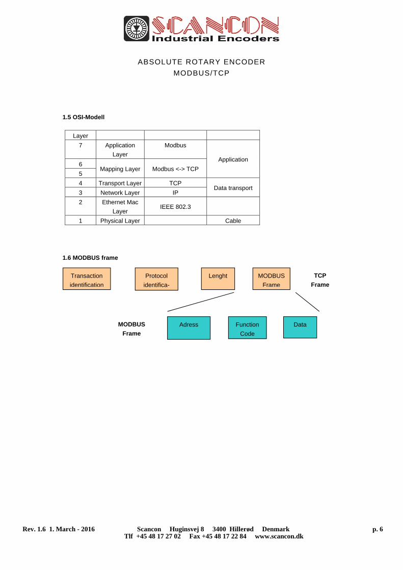
1.5 OSI-Modell
Layer
7 Application
Layer
Modbus
Application 6
Mapping Layer Modbus <-> TCP 5
4 Transport Layer TCP Data transport
3 Network Layer IP
2 Ethernet Mac
Layer IEEE 802.3
1 Physical Layer Cable
1.6 MODBUS frame
Transaction
identification
Protocol
identifica-
Lenght MODBUS
Frame
Adress Function
Code
Data
TCP
Frame
MODBUS
Frame
ABSOLUTE ROTARY ENCODER
MODBUS/TCP
Rev. 1.6 1. March - 2016 Scancon Huginsvej 8 3400 Hillerød Denmark p. 7 Tlf +45 48 17 27 02 Fax +45 48 17 22 84 www.scancon.dk
2 Hardware Set-Up and Ethernet Connection
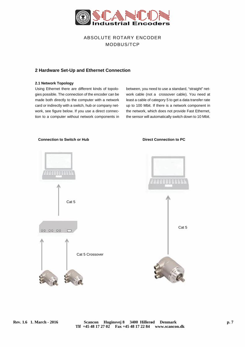
2.1 Network Topology
Using Ethernet there are different kinds of topolo-
gies possible. The connection of the encoder can be
made both directly to the computer with a network
card or indirectly with a switch, hub or company net-
work, see figure below. If you use a direct connec-
tion to a computer without network components in
between, you need to use a standard, “straight” net-
work cable (not a crossover cable). You need at
least a cable of category 5 to get a data transfer rate
up to 100 Mbit. If there is a network component in
the network, which does not provide Fast Ethernet,
the sensor will automatically switch down to 10 Mbit.
Connection to Switch or Hub Direct Connection to PC
Cat 5
Cat 5
Cat 5 Crossover
ABSOLUTE ROTARY ENCODER
MODBUS/TCP
Rev. 1.6 1. March - 2016 Scancon Huginsvej 8 3400 Hillerød Denmark p. 8 Tlf +45 48 17 27 02 Fax +45 48 17 22 84 www.scancon.dk
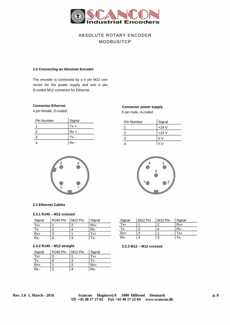
2.2 Connecting an Absolute Encoder
The encoder is connected by a 5 pin M12 con-
nector for the power supply and one 4 pin,
D-coded M12 connector for Ethernet.
Connector Ethernet
4 pin female, D-coded
Connector power supply
5 pin male, A-coded
2.3 Ethernet Cables
2.3.1 RJ45 – M12 crossed
Signal RJ45 Pin M12 Pin Signal
Tx+ 1 2 Rx+ Tx- 2 4 Rx- Rx+ 3 1 Tx+ Rx- 6 3 Tx-
2.3.2 RJ45 – M12 straight
Signal RJ45 Pin M12 Pin Signal Tx+ 3 1 Tx+ Tx- 6 3 Tx- Rx+ 1 2 Rx+ Rx- 2 4 Rx-
2.3.3 M12 – M12 crossed
Signal M12 Pin M12 Pin Signal Tx+ 1 2 Rx+ Tx- 3 4 Rx- Rx+ 2 1 Tx+ Rx- 4 3 Tx-
Pin Number Signal
1 +24 V
2 +24 V
3 0 V
4 0 V
Pin Number Signal
1 Tx +
2 Rx +
3 Tx -
4 Rx -
ABSOLUTE ROTARY ENCODER
MODBUS/TCP
Rev. 1.6 1. March - 2016 Scancon Huginsvej 8 3400 Hillerød Denmark p. 9 Tlf +45 48 17 27 02 Fax +45 48 17 22 84 www.scancon.dk
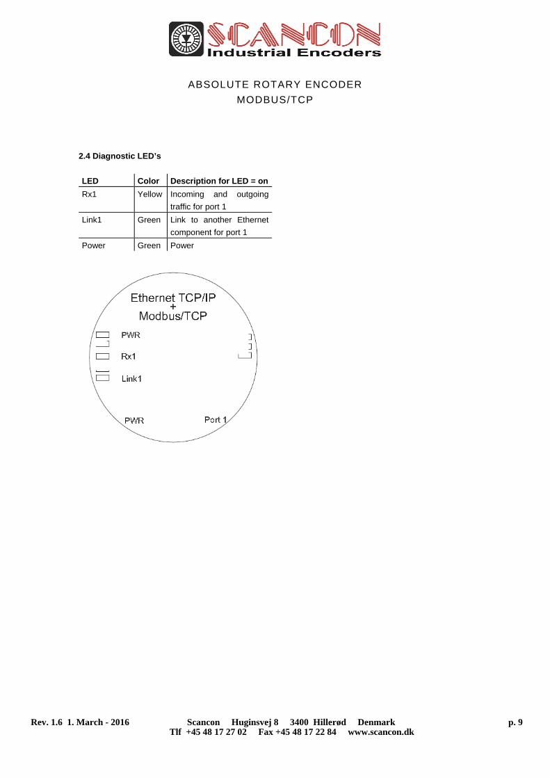
2.4 Diagnostic LED’s
LED Color Description for LED = on
Rx1 Yellow Incoming and outgoing
traffic for port 1
Link1 Green Link to another Ethernet
component for port 1
Power Green Power
ABSOLUTE ROTARY ENCODER
MODBUS/TCP
Rev. 1.6 1. March - 2016 Scancon Huginsvej 8 3400 Hillerød Denmark p. 10 Tlf +45 48 17 27 02 Fax +45 48 17 22 84 www.scancon.dk
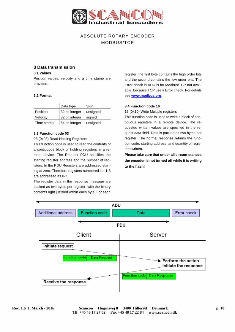
3 Data transmission 3.1 Values
Position values, velocity and a time stamp are
provided.
3.2 Format
Data type Sign
Position 32 bit integer unsigned
Velocity 32 bit integer signed
Time stamp 64 bit integer unsigned
3.3 Function code 03
03 (0x03) Read Holding Registers
This function code is used to read the contents of
a contiguous block of holding registers in a re-
mote device. The Request PDU specifies the
starting register address and the number of reg-
isters. In the PDU Registers are addressed start-
ing at zero. Therefore registers numbered i.e. 1-8
are addressed as 0-7.
The register data in the response message are
packed as two bytes per register, with the binary
contents right justified within each byte. For each
register, the first byte contains the high order bits
and the second contains the low order bits. The
Error check in ADU is for Modbus/TCP not avail-
able, because TCP use a Error check. For details
see www.modbus.org.
3.4 Function code 16
16 (0x10) Write Multiple registers
This function code is used to write a block of con-
tiguous registers in a remote device. The re-
quested written values are specified in the re-
quest data field. Data is packed as two bytes per
register. The normal response returns the func-
tion code, starting address, and quantity of regis-
ters written.
Please take care that under all circum-stances
the encoder is not turned off while it is writing
to the flash!
ABSOLUTE ROTARY ENCODER
MODBUS/TCP
Rev. 1.6 1. March - 2016 Scancon Huginsvej 8 3400 Hillerød Denmark p. 11 Tlf +45 48 17 27 02 Fax +45 48 17 22 84 www.scancon.dk
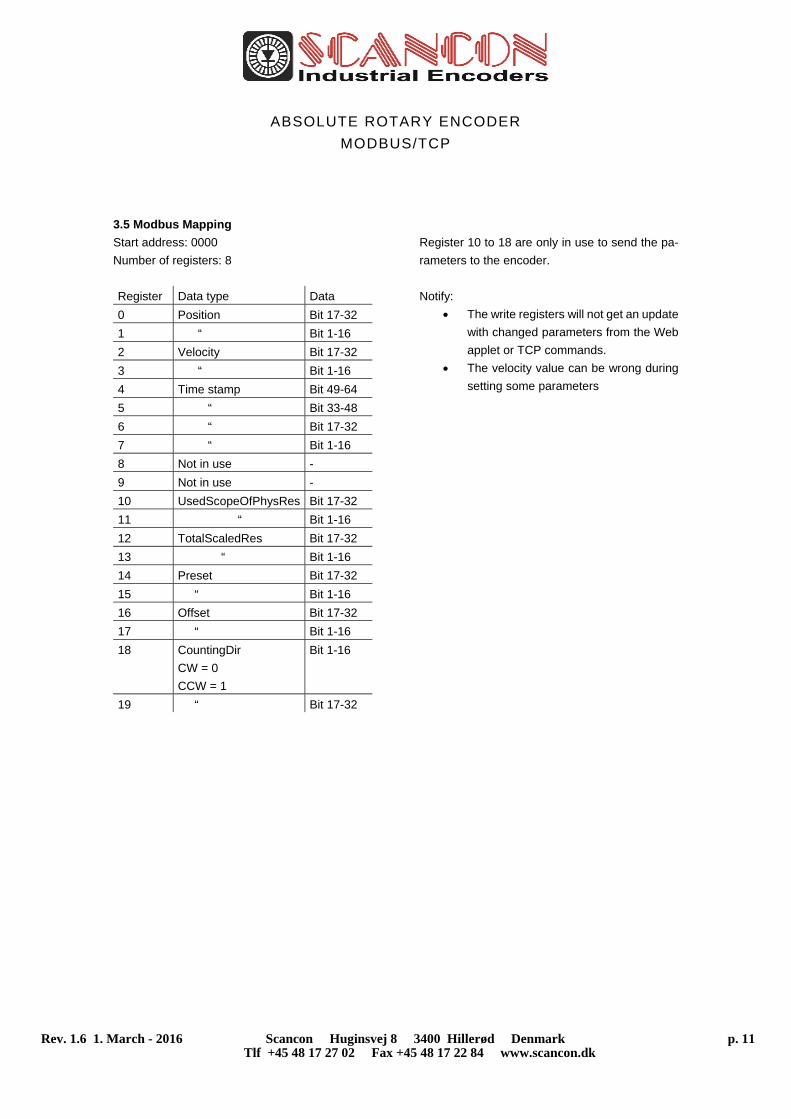
3.5 Modbus Mapping
Start address: 0000
Number of registers: 8
Register Data type Data
0 Position Bit 17-32
1 “ Bit 1-16
2 Velocity Bit 17-32
3 “ Bit 1-16
4 Time stamp Bit 49-64
5 “ Bit 33-48
6 “ Bit 17-32
7 “ Bit 1-16
8 Not in use -
9 Not in use -
10 UsedScopeOfPhysRes Bit 17-32
11 “ Bit 1-16
12 TotalScaledRes Bit 17-32
13 “ Bit 1-16
14 Preset Bit 17-32
15 “ Bit 1-16
16 Offset Bit 17-32
17 “ Bit 1-16
18 CountingDir
CW = 0
CCW = 1
Bit 1-16
19 “ Bit 17-32
Register 10 to 18 are only in use to send the pa-
rameters to the encoder.
Notify:
The write registers will not get an update
with changed parameters from the Web
applet or TCP commands.
The velocity value can be wrong during
setting some parameters
ABSOLUTE ROTARY ENCODER
MODBUS/TCP
Rev. 1.6 1. March - 2016 Scancon Huginsvej 8 3400 Hillerød Denmark p. 12 Tlf +45 48 17 27 02 Fax +45 48 17 22 84 www.scancon.dk
4 Programming
4.1 Programming of Parameters
The encoder is able to provide three different kinds of output data: the position value, a velocity value and a
time stamp. These can be used in arbitrary combinations.
Parameter Description
Used scope of physical resolution
(parameter 1)
Specifies the part of the physical resolution used for the encoder in
physical steps. If e.g. for an encoder with a resolution of 8192 steps
per revolution 16384 is chosen, the encoder will count 8192 steps per
revolution (if “Total scaled resolution” is set to the same value as “Used
scope of physical resolution”) and start with zero again after 2 revolu-
tions. If this value is not set to a value which results in an integer divi-
sion with the total physical resolution, the encoder value will jump to
zero when passing the physical zero point.
Total scaled resolution
(parameter 2)
Specifies the scaled resolution which is used over the area of physical
steps defined by “Used scope of physical resolution”. If e.g. the en-
coder is set as described above and “Total scaled resolution” is set to
10, the encoder will count 10 steps over the physical steps defined
with “Used scope of physical resolution”, i.e. 5 steps per revolution.
Code sequence The code sequence (complement) can be programmed as an operat-
ing parameter. This parameter determines whether the output code
increases or decreases when the axis is turned clockwise.
Preset value The Preset value is the desired output value for the actual position of
the axis. The actual output value will be set to this preset value.
Please note the FAQ for important information!
Offset value The offset value can set the offset to physical position of the axis.
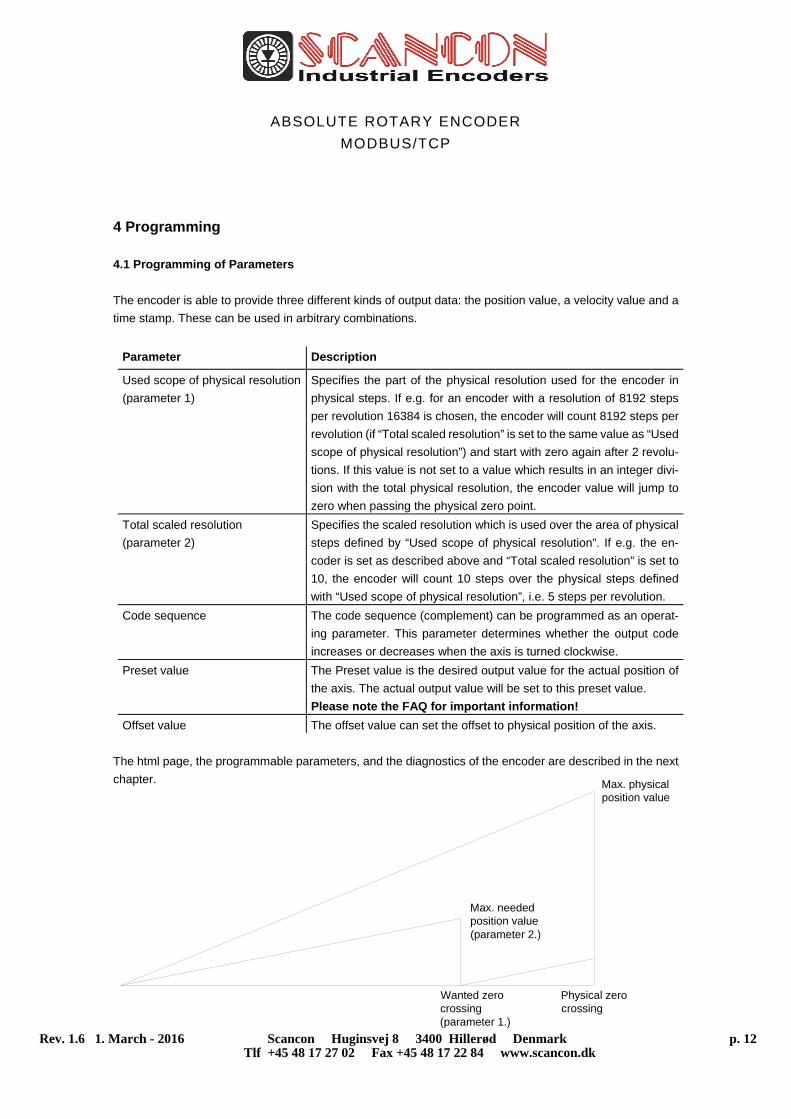
The html page, the programmable parameters, and the diagnostics of the encoder are described in the next
chapter.
Physical zero crossing
Wanted zero crossing(parameter 1.)
Max. needed position value(parameter 2.)
Max. physical position value
ABSOLUTE ROTARY ENCODER
MODBUS/TCP
Rev. 1.6 1. March - 2016 Scancon Huginsvej 8 3400 Hillerød Denmark p. 13 Tlf +45 48 17 27 02 Fax +45 48 17 22 84 www.scancon.dk
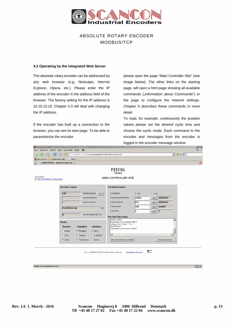
4.2 Operating by the integrated Web Server
The absolute rotary encoder can be addressed by
any web browser (e.g. Netscape, Internet
Explorer, Opera, etc.). Please enter the IP
address of the encoder in the address field of the
browser. The factory setting for the IP address is
10.10.10.10. Chapter 4.3 will deal with changing
the IP address.
If the encoder has built up a connection to the
browser, you can see its start page. To be able to
parameterize the encoder
please open the page “Main Controller Site“ (see
image below). The other links on the starting
page, will open a html page showing all available
commands („Information about Commands“) or
the page to configure the network settings.
Chapter 5 describes these commands in more
detail.
To read, for example, continuously the position
values please set the desired cycle time and
choose the cyclic mode. Each command to the
encoder and messages from the encoder is
logged in the encoder message window.
ABSOLUTE ROTARY ENCODER
MODBUS/TCP
Rev. 1.6 1. March - 2016 Scancon Huginsvej 8 3400 Hillerød Denmark p. 14 Tlf +45 48 17 27 02 Fax +45 48 17 22 84 www.scancon.dk
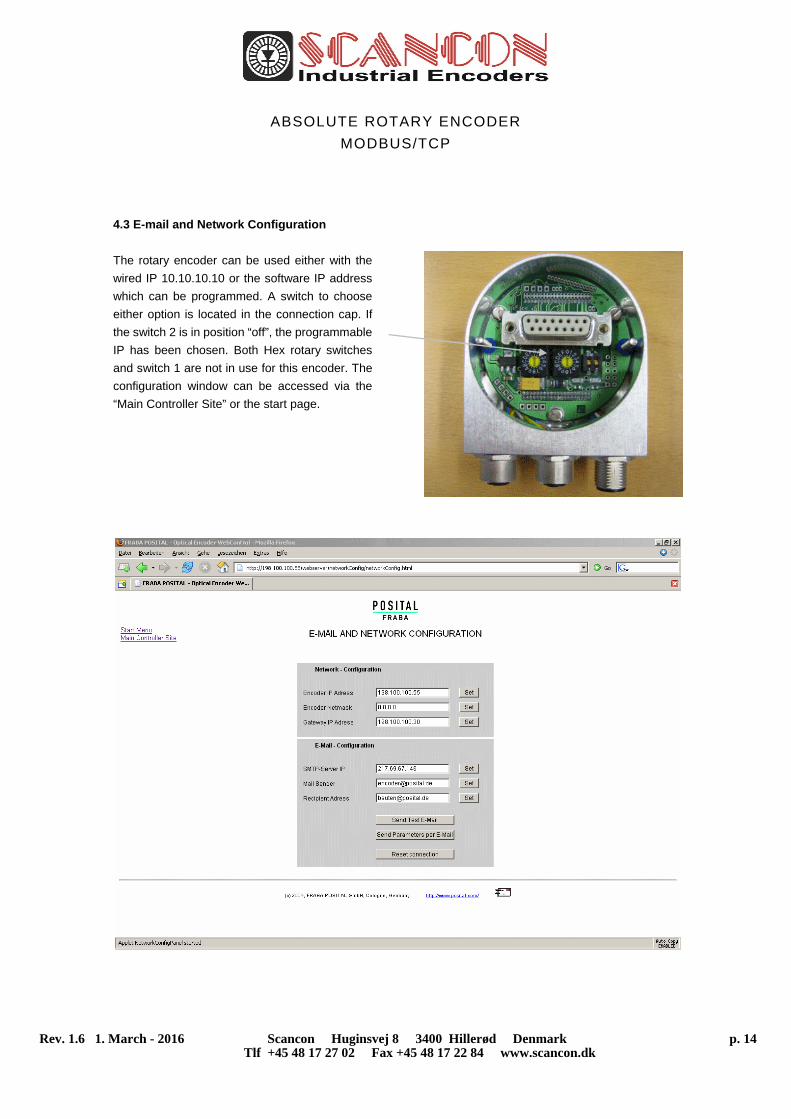
4.3 E-mail and Network Configuration
The rotary encoder can be used either with the
wired IP 10.10.10.10 or the software IP address
which can be programmed. A switch to choose
either option is located in the connection cap. If
the switch 2 is in position “off”, the programmable
IP has been chosen. Both Hex rotary switches
and switch 1 are not in use for this encoder. The
configuration window can be accessed via the
“Main Controller Site” or the start page.
ABSOLUTE ROTARY ENCODER
MODBUS/TCP
Rev. 1.6 1. March - 2016 Scancon Huginsvej 8 3400 Hillerød Denmark p. 15 Tlf +45 48 17 27 02 Fax +45 48 17 22 84 www.scancon.dk
5 Operating by TCP/IP Commands
5.1 Introduction
To use the absolute encoder with a control system
platform independent commands and data in ASCII
format can be exchanged by TCP/IP. To take a look
at the commands and a short description please see
chapter 5.6. To find out how to address the TCP/IP
interface of your control or operating system please
refer to the documentation for these devices
If you use a Windows PC, you can try the following
connection to the sensor: Go to the command
prompt (DOS) and type in “ping <computer-name>”
or “ipconfig”. In response you get the IP address of
your computer. If the encoder IP address is not
located within your subnet mask, you will need to
prepare the data transfer to the encoder by entering
the command “route add <IP-sensor> <IP-
computer>“. Maybe are administrator rights
necessary. Otherwise your PC/control system will
try to reach the encoder via your computers
standard gateway. The default IP address of the
sensor is 10.10.10.10. You can check the
connection to the sensor with the command “ping
<IP-sensor>“.
5.2 Installation
To communicate with the Encoder using our
example tools tcpcl or updcl, a Java runtime
environment is required on your PC. If you have not
installed Java, you can get it from our CD (look
under the section “accessories”). You can also
download the latest version from
http://java.sun.com/products/j2se. Copy the
FRABA-Java programs which you can find on our
website
https://www.posital.com/media/fraba/productfinder/
posital/tools-ixarc-ocd-em-java_client.zip
onto your hard disk, e.g. in the folder
c:\fraba\ethernet.
Afterwards you need to set up the PATH variable for
the Java installation and the FRABA-Java
programs. For a convenient start we also provided
batch files to start the java files, depending on the
IP addresses you might need to modify them. For
TCP will be used port 6000.
5.3 PATH Variable
5.3.1 MS-DOS, Win95, Win98, WinME
Please add the required paths to c:\Autoexec.bat
behind the “Path” line. Example:
Path=c:\ms-dos; c:\Program Files\BC\BIN
Path=%Path%;c:\fraba\ethernet\
Path=%Path%;c:\programme\java\bin
ABSOLUTE ROTARY ENCODER
MODBUS/TCP
Rev. 1.6 1. March - 2016 Scancon Huginsvej 8 3400 Hillerød Denmark p. 16 Tlf +45 48 17 27 02 Fax +45 48 17 22 84 www.scancon.dk
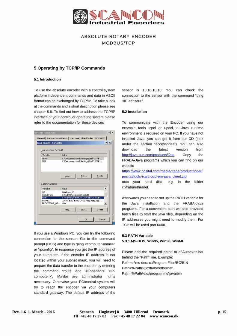
5.3.2 WinNT3.51, WinNT4, Win2000, WinXP
In Start – Settings – Control panel – System –
Advanced – Environment Variables you can
configure the variable “Path”. Please do not
change the other path settings, but only add the
required paths! Depending on the operating system
used administrator rights might be necessary.
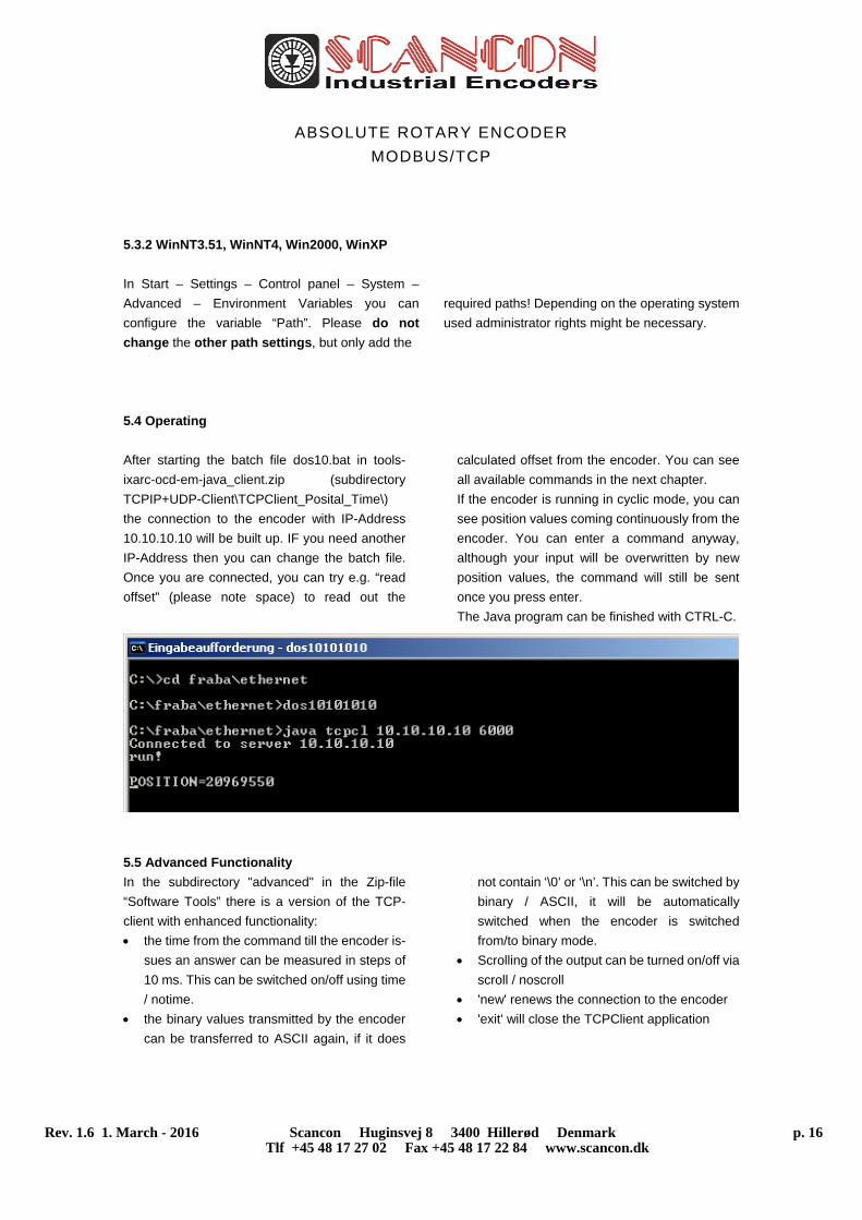
5.4 Operating
After starting the batch file dos10.bat in tools-
ixarc-ocd-em-java_client.zip (subdirectory
TCPIP+UDP-Client\TCPClient_Posital_Time\)
the connection to the encoder with IP-Address
10.10.10.10 will be built up. IF you need another
IP-Address then you can change the batch file.
Once you are connected, you can try e.g. “read
offset” (please note space) to read out the
calculated offset from the encoder. You can see
all available commands in the next chapter.
If the encoder is running in cyclic mode, you can
see position values coming continuously from the
encoder. You can enter a command anyway,
although your input will be overwritten by new
position values, the command will still be sent
once you press enter.
The Java program can be finished with CTRL-C.
5.5 Advanced Functionality
In the subdirectory "advanced" in the Zip-file
“Software Tools” there is a version of the TCP-
client with enhanced functionality:
the time from the command till the encoder is-
sues an answer can be measured in steps of
10 ms. This can be switched on/off using time
/ notime.
the binary values transmitted by the encoder
can be transferred to ASCII again, if it does
not contain ‘\0’ or ‘\n’. This can be switched by
binary / ASCII, it will be automatically
switched when the encoder is switched
from/to binary mode.
Scrolling of the output can be turned on/off via
scroll / noscroll
'new' renews the connection to the encoder
'exit' will close the TCPClient application
ABSOLUTE ROTARY ENCODER
MODBUS/TCP
Rev. 1.6 1. March - 2016 Scancon Huginsvej 8 3400 Hillerød Denmark p. 17 Tlf +45 48 17 27 02 Fax +45 48 17 22 84 www.scancon.dk
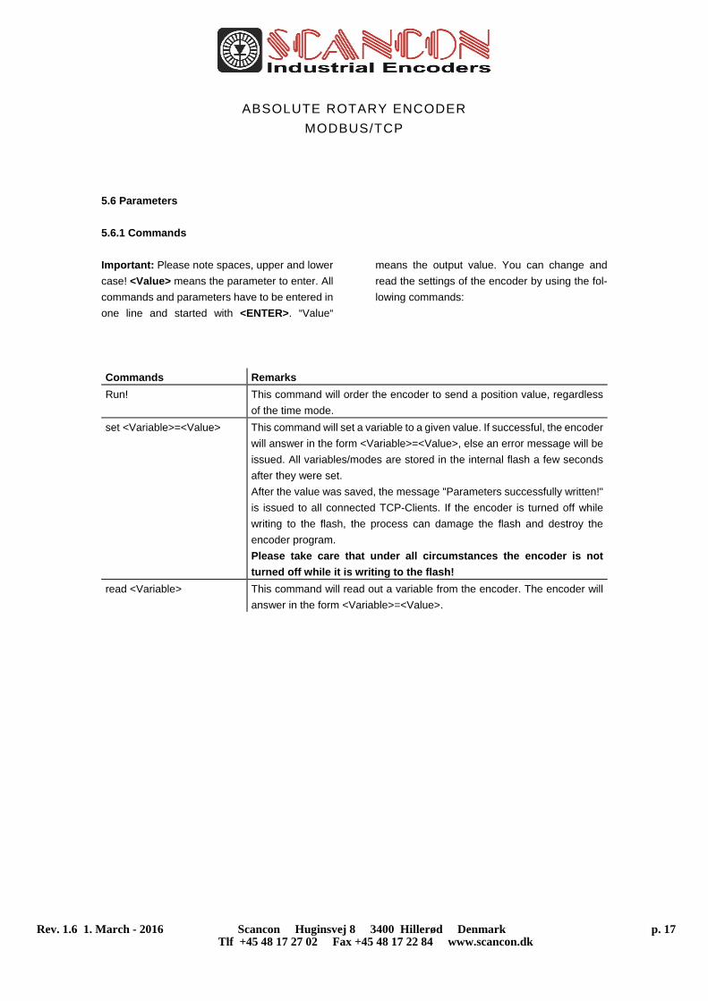
5.6 Parameters
5.6.1 Commands
Important: Please note spaces, upper and lower
case! <Value> means the parameter to enter. All
commands and parameters have to be entered in
one line and started with <ENTER>. “Value“
means the output value. You can change and
read the settings of the encoder by using the fol-
lowing commands:
Commands Remarks
Run! This command will order the encoder to send a position value, regardless
of the time mode.
set <Variable>=<Value> This command will set a variable to a given value. If successful, the encoder
will answer in the form <Variable>=<Value>, else an error message will be
issued. All variables/modes are stored in the internal flash a few seconds
after they were set.
After the value was saved, the message "Parameters successfully written!"
is issued to all connected TCP-Clients. If the encoder is turned off while
writing to the flash, the process can damage the flash and destroy the
encoder program.
Please take care that under all circumstances the encoder is not
turned off while it is writing to the flash!
read <Variable> This command will read out a variable from the encoder. The encoder will
answer in the form <Variable>=<Value>.
ABSOLUTE ROTARY ENCODER
MODBUS/TCP
Rev. 1.6 1. March - 2016 Scancon Huginsvej 8 3400 Hillerød Denmark p. 18 Tlf +45 48 17 27 02 Fax +45 48 17 22 84 www.scancon.dk
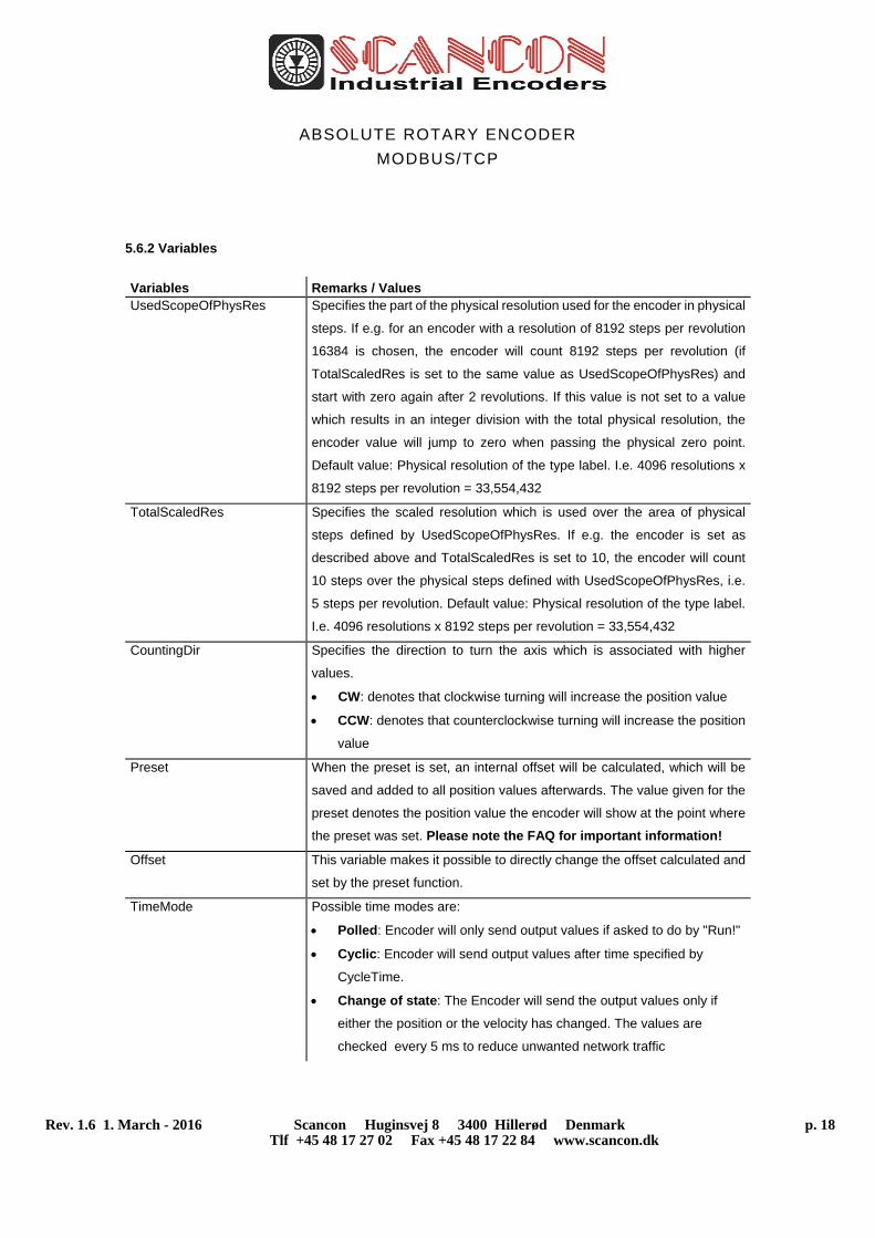
5.6.2 Variables
Variables Remarks / Values UsedScopeOfPhysRes Specifies the part of the physical resolution used for the encoder in physical
steps. If e.g. for an encoder with a resolution of 8192 steps per revolution
16384 is chosen, the encoder will count 8192 steps per revolution (if
TotalScaledRes is set to the same value as UsedScopeOfPhysRes) and
start with zero again after 2 revolutions. If this value is not set to a value
which results in an integer division with the total physical resolution, the
encoder value will jump to zero when passing the physical zero point.
Default value: Physical resolution of the type label. I.e. 4096 resolutions x
8192 steps per revolution = 33,554,432
TotalScaledRes Specifies the scaled resolution which is used over the area of physical
steps defined by UsedScopeOfPhysRes. If e.g. the encoder is set as
described above and TotalScaledRes is set to 10, the encoder will count
10 steps over the physical steps defined with UsedScopeOfPhysRes, i.e.
5 steps per revolution. Default value: Physical resolution of the type label.
I.e. 4096 resolutions x 8192 steps per revolution = 33,554,432
CountingDir Specifies the direction to turn the axis which is associated with higher
values.
CW: denotes that clockwise turning will increase the position value
CCW: denotes that counterclockwise turning will increase the position
value
Preset When the preset is set, an internal offset will be calculated, which will be
saved and added to all position values afterwards. The value given for the
preset denotes the position value the encoder will show at the point where
the preset was set. Please note the FAQ for important information!
Offset This variable makes it possible to directly change the offset calculated and
set by the preset function.
TimeMode Possible time modes are:
Polled: Encoder will only send output values if asked to do by "Run!"
Cyclic: Encoder will send output values after time specified by
CycleTime.
Change of state: The Encoder will send the output values only if
either the position or the velocity has changed. The values are
checked every 5 ms to reduce unwanted network traffic
ABSOLUTE ROTARY ENCODER
MODBUS/TCP
Rev. 1.6 1. March - 2016 Scancon Huginsvej 8 3400 Hillerød Denmark p. 19 Tlf +45 48 17 27 02 Fax +45 48 17 22 84 www.scancon.dk
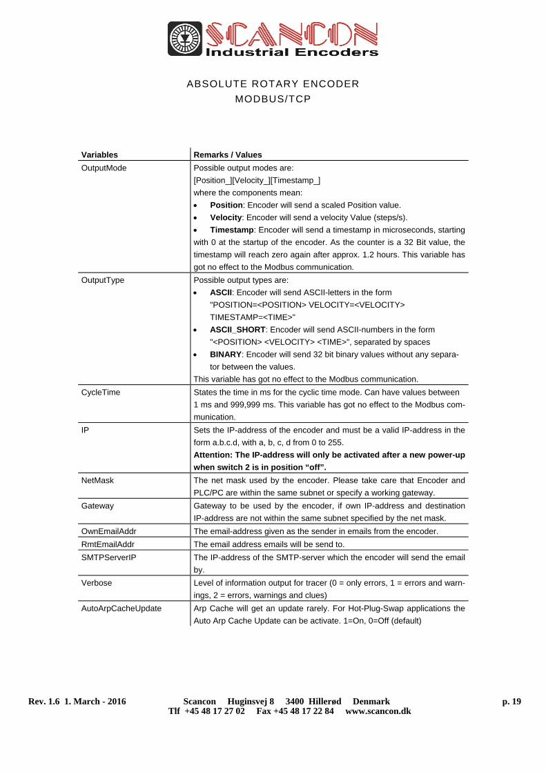
Variables Remarks / Values
OutputMode Possible output modes are:
[Position_][Velocity_][Timestamp_]
where the components mean:
Position: Encoder will send a scaled Position value.
Velocity: Encoder will send a velocity Value (steps/s).
Timestamp: Encoder will send a timestamp in microseconds, starting
with 0 at the startup of the encoder. As the counter is a 32 Bit value, the
timestamp will reach zero again after approx. 1.2 hours. This variable has
got no effect to the Modbus communication.
OutputType Possible output types are:
ASCII: Encoder will send ASCII-letters in the form
"POSITION=<POSITION> VELOCITY=<VELOCITY>
TIMESTAMP=<TIME>"
ASCII_SHORT: Encoder will send ASCII-numbers in the form
"<POSITION> <VELOCITY> <TIME>", separated by spaces
BINARY: Encoder will send 32 bit binary values without any separa-
tor between the values.
This variable has got no effect to the Modbus communication.
CycleTime States the time in ms for the cyclic time mode. Can have values between
1 ms and 999,999 ms. This variable has got no effect to the Modbus com-
munication.
IP Sets the IP-address of the encoder and must be a valid IP-address in the
form a.b.c.d, with a, b, c, d from 0 to 255.
Attention: The IP-address will only be activated after a new power-up
when switch 2 is in position “off”.
NetMask The net mask used by the encoder. Please take care that Encoder and
PLC/PC are within the same subnet or specify a working gateway.
Gateway Gateway to be used by the encoder, if own IP-address and destination
IP-address are not within the same subnet specified by the net mask.
OwnEmailAddr The email-address given as the sender in emails from the encoder.
RmtEmailAddr The email address emails will be send to.
SMTPServerIP The IP-address of the SMTP-server which the encoder will send the email
by.
Verbose Level of information output for tracer (0 = only errors, 1 = errors and warn-
ings, 2 = errors, warnings and clues)
AutoArpCacheUpdate
Arp Cache will get an update rarely. For Hot-Plug-Swap applications the
Auto Arp Cache Update can be activate. 1=On, 0=Off (default)
ABSOLUTE ROTARY ENCODER
MODBUS/TCP
Rev. 1.6 1. March - 2016 Scancon Huginsvej 8 3400 Hillerød Denmark p. 20 Tlf +45 48 17 27 02 Fax +45 48 17 22 84 www.scancon.dk
5.6.3 Encoder answers
Encoder answers Remarks
<Variable>=<Value> If a variable was correctly set, the encoder will answer to all connected
TCP-clients with the variable and its new value. This indicates that the En-
coder understood the command and now uses the value, it does not indi-
cate that the value was already save to the internal Flash, please allow
some additional seconds for that.
ERROR: ... If something went wrong, the encoder will issue an error, e.g. if it did not
understand a command or if a value for a variable was not correct. It will
describe the error after the "ERROR:" tag.
WARNING: ... If a variable was set to a value, which is permitted, but which may result in
problems when certain conditions occur, the encoder will issue a warning.
This could for example happen, if the variable UsedScopeOfPhysRes is set
to a value which does not result in an integer division with the physical res-
olution of the encoder when dividing the total physical resolution of the en-
coder. The reason for the warning will be sent following the "WARNING:"
tag.
Parameters successfully
written!
If any variable was set, it is important to wait until the encoder displays
this message before the encoder can be turned off, otherwise the in-
ternal flash might be damaged.
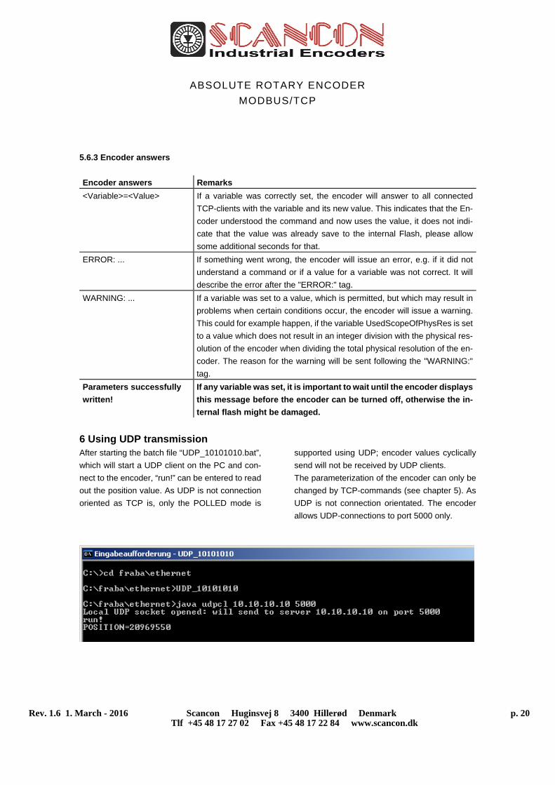
6 Using UDP transmission After starting the batch file “UDP_10101010.bat”,
which will start a UDP client on the PC and con-
nect to the encoder, “run!” can be entered to read
out the position value. As UDP is not connection
oriented as TCP is, only the POLLED mode is
supported using UDP; encoder values cyclically
send will not be received by UDP clients.
The parameterization of the encoder can only be
changed by TCP-commands (see chapter 5). As
UDP is not connection orientated. The encoder
allows UDP-connections to port 5000 only.

ABSOLUTE ROTARY ENCODER
MODBUS/TCP
Rev. 1.6 1. March - 2016 Scancon Huginsvej 8 3400 Hillerød Denmark p. 21 Tlf +45 48 17 27 02 Fax +45 48 17 22 84 www.scancon.dk
7 FAQ
1. Question: Why cannot set the Preset value more than one time?
Answer: The Preset value will save in the flash of the encoder. This flash has only writing
cycles of 100000 times. If the register 14+15 is in use to set the Preset value it could be that
thousands of cycles will save in the flash and the life time of the encoder decrease signifi-
cant. So we fix it that it is not possible to save the same preset value for more than one time.
The next preset value must be different, but can use in the next but one. I.e. Preset value is
0. Then set in the first time 0, in the second 1, in the next one 0, ...
2. Question: With which PLC can the encoder work too?
Answer: SEND/RECEIVE is an easy open protocol, that can be used by different PLC's like
Siemens (S7-1200), Hima, ...
3. Question: Physical zero point problems
Answer: You can set only the Preset value. The offset value is only the result. If you would
like to set the encoder position to the half of physical resolution you have to do the following
steps:
a. Set preset value to a value so that the offset value is zero.
b. Rotate the shaft i.e. to 16777216
c. Set the Preset value to the wished value.
4. Question: Minimum sensor update time
Answer: The internal sensor update time amounts ~2 ms. Temporary the update time was
between Version 4.2 and 4.5 only 10 ms. But this fast transmission time is only possible with
UDP. According the basic of TCP-IP and the network traffic this product cannot guarantee
real time applications.
5. Question: How to use a redundant PLC?
Answer: If the encoder should work on a Hot-Plug-Swap application it is necessary to acti-
vate the Auto Arp Cache update. Send to the encoder Set AutoArpCacheUpdate=1
But please note that this decrease the response time.
6. Question: Compatibility to OCD-ETA1B-…
Answer: OCD-EM… is the 1:1 replacement.
ABSOLUTE ROTARY ENCODER
MODBUS/TCP
Rev. 1.6 1. March - 2016 Scancon Huginsvej 8 3400 Hillerød Denmark p. 22 Tlf +45 48 17 27 02 Fax +45 48 17 22 84 www.scancon.dk
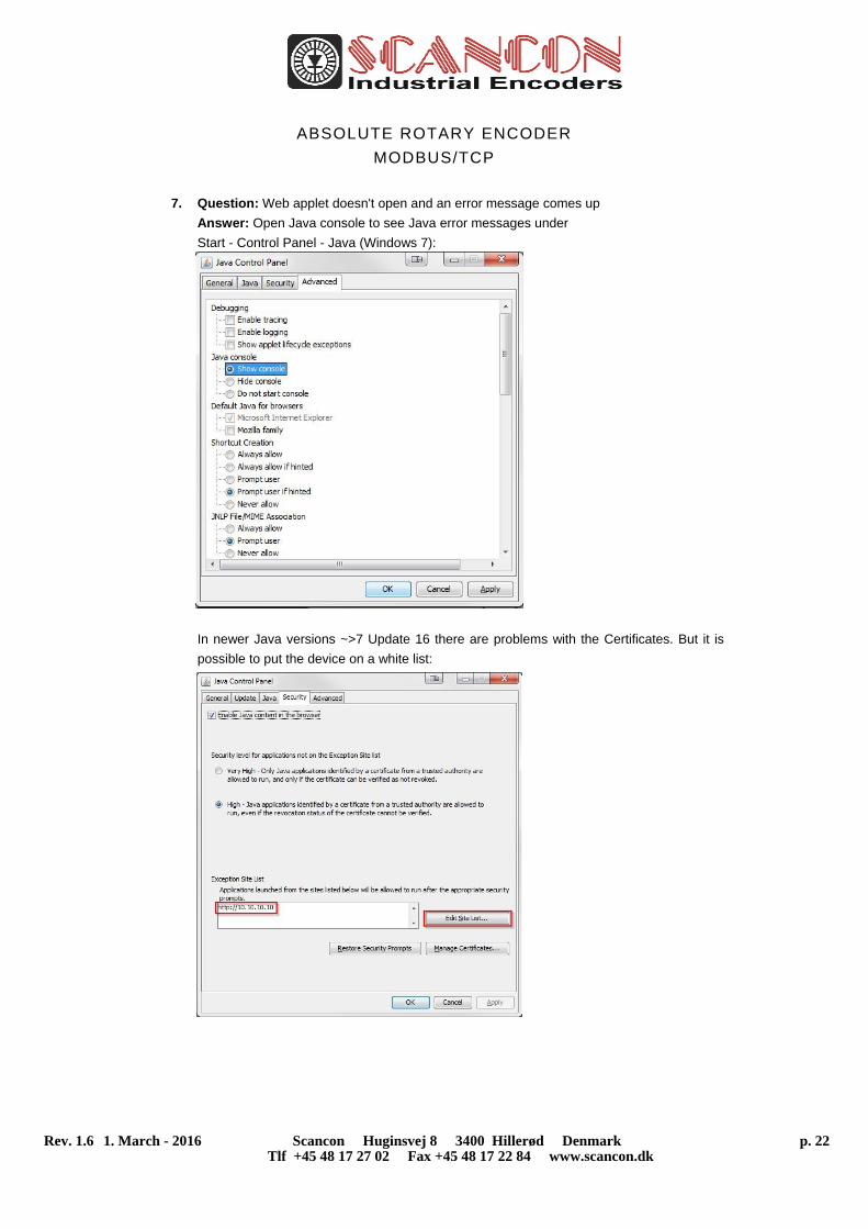
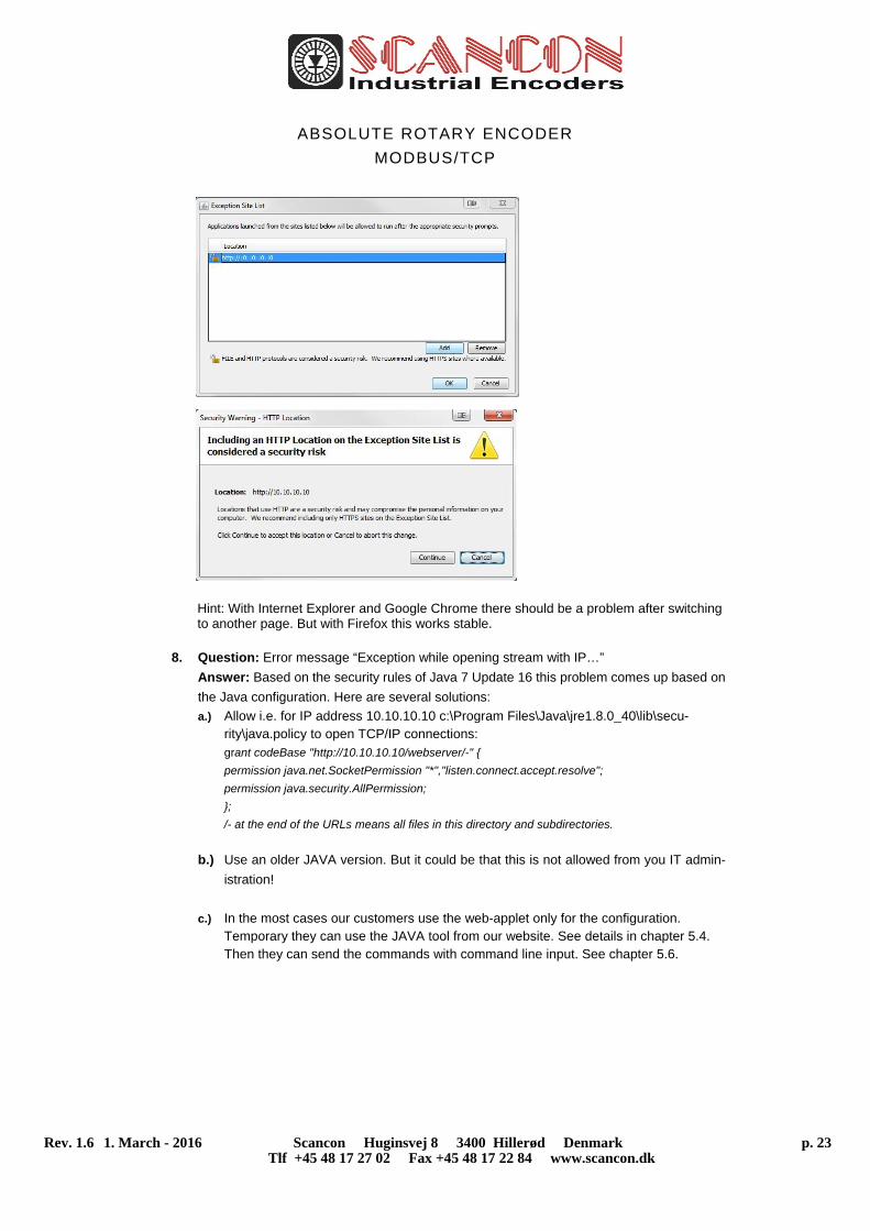
7. Question: Web applet doesn't open and an error message comes up
Answer: Open Java console to see Java error messages under
Start - Control Panel - Java (Windows 7):
In newer Java versions ~>7 Update 16 there are problems with the Certificates. But it is
possible to put the device on a white list:
ABSOLUTE ROTARY ENCODER
MODBUS/TCP
Rev. 1.6 1. March - 2016 Scancon Huginsvej 8 3400 Hillerød Denmark p. 23 Tlf +45 48 17 27 02 Fax +45 48 17 22 84 www.scancon.dk
Hint: With Internet Explorer and Google Chrome there should be a problem after switching to another page. But with Firefox this works stable.
8. Question: Error message “Exception while opening stream with IP…”
Answer: Based on the security rules of Java 7 Update 16 this problem comes up based on
the Java configuration. Here are several solutions:
a.) Allow i.e. for IP address 10.10.10.10 c:\Program Files\Java\jre1.8.0_40\lib\secu-rity\java.policy to open TCP/IP connections: grant codeBase "http://10.10.10.10/webserver/-" {
permission java.net.SocketPermission "*","listen.connect.accept.resolve";
permission java.security.AllPermission;
};
/- at the end of the URLs means all files in this directory and subdirectories.
b.) Use an older JAVA version. But it could be that this is not allowed from you IT admin-
istration!
c.) In the most cases our customers use the web-applet only for the configuration. Temporary they can use the JAVA tool from our website. See details in chapter 5.4. Then they can send the commands with command line input. See chapter 5.6.
ABSOLUTE ROTARY ENCODER
MODBUS/TCP
Rev. 1.6 1. March - 2016 Scancon Huginsvej 8 3400 Hillerød Denmark p. 24 Tlf +45 48 17 27 02 Fax +45 48 17 22 84 www.scancon.dk
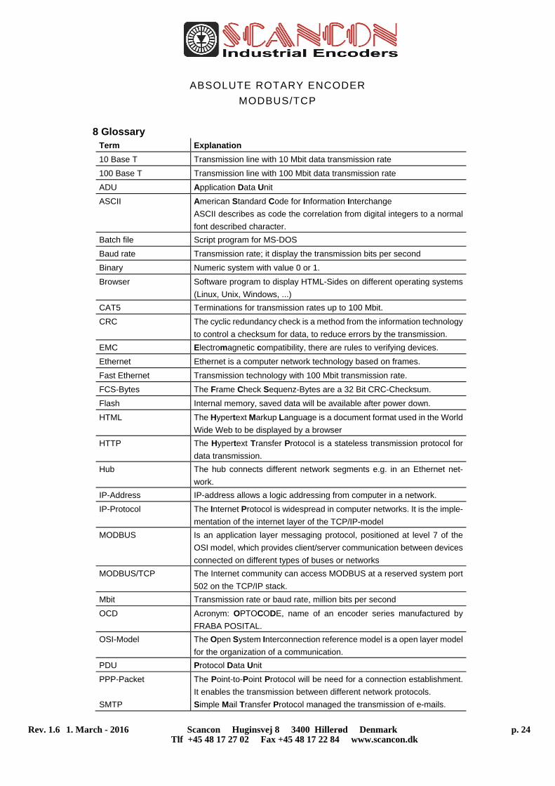
8 Glossary Term Explanation
10 Base T Transmission line with 10 Mbit data transmission rate
100 Base T Transmission line with 100 Mbit data transmission rate
ADU Application Data Unit
ASCII American Standard Code for Information Interchange
ASCII describes as code the correlation from digital integers to a normal
font described character.
Batch file Script program for MS-DOS
Baud rate Transmission rate; it display the transmission bits per second
Binary Numeric system with value 0 or 1.
Browser Software program to display HTML-Sides on different operating systems
(Linux, Unix, Windows, ...)
CAT5 Terminations for transmission rates up to 100 Mbit.
CRC The cyclic redundancy check is a method from the information technology
to control a checksum for data, to reduce errors by the transmission.
EMC Electromagnetic compatibility, there are rules to verifying devices.
Ethernet Ethernet is a computer network technology based on frames.
Fast Ethernet Transmission technology with 100 Mbit transmission rate.
FCS-Bytes The Frame Check Sequenz-Bytes are a 32 Bit CRC-Checksum.
Flash Internal memory, saved data will be available after power down.
HTML The Hypertext Markup Language is a document format used in the World
Wide Web to be displayed by a browser
HTTP The Hypertext Transfer Protocol is a stateless transmission protocol for
data transmission.
Hub The hub connects different network segments e.g. in an Ethernet net-
work.
IP-Address IP-address allows a logic addressing from computer in a network.
IP-Protocol The Internet Protocol is widespread in computer networks. It is the imple-
mentation of the internet layer of the TCP/IP-model
MODBUS Is an application layer messaging protocol, positioned at level 7 of the
OSI model, which provides client/server communication between devices
connected on different types of buses or networks
MODBUS/TCP The Internet community can access MODBUS at a reserved system port
502 on the TCP/IP stack.
Mbit Transmission rate or baud rate, million bits per second
OCD Acronym: OPTOCODE, name of an encoder series manufactured by
FRABA POSITAL.
OSI-Model The Open System Interconnection reference model is a open layer model
for the organization of a communication.
PDU Protocol Data Unit
PPP-Packet The Point-to-Point Protocol will be need for a connection establishment.
It enables the transmission between different network protocols.
SMTP Simple Mail Transfer Protocol managed the transmission of e-mails.
ABSOLUTE ROTARY ENCODER
MODBUS/TCP
Rev. 1.6 1. March - 2016 Scancon Huginsvej 8 3400 Hillerød Denmark p. 25 Tlf +45 48 17 27 02 Fax +45 48 17 22 84 www.scancon.dk
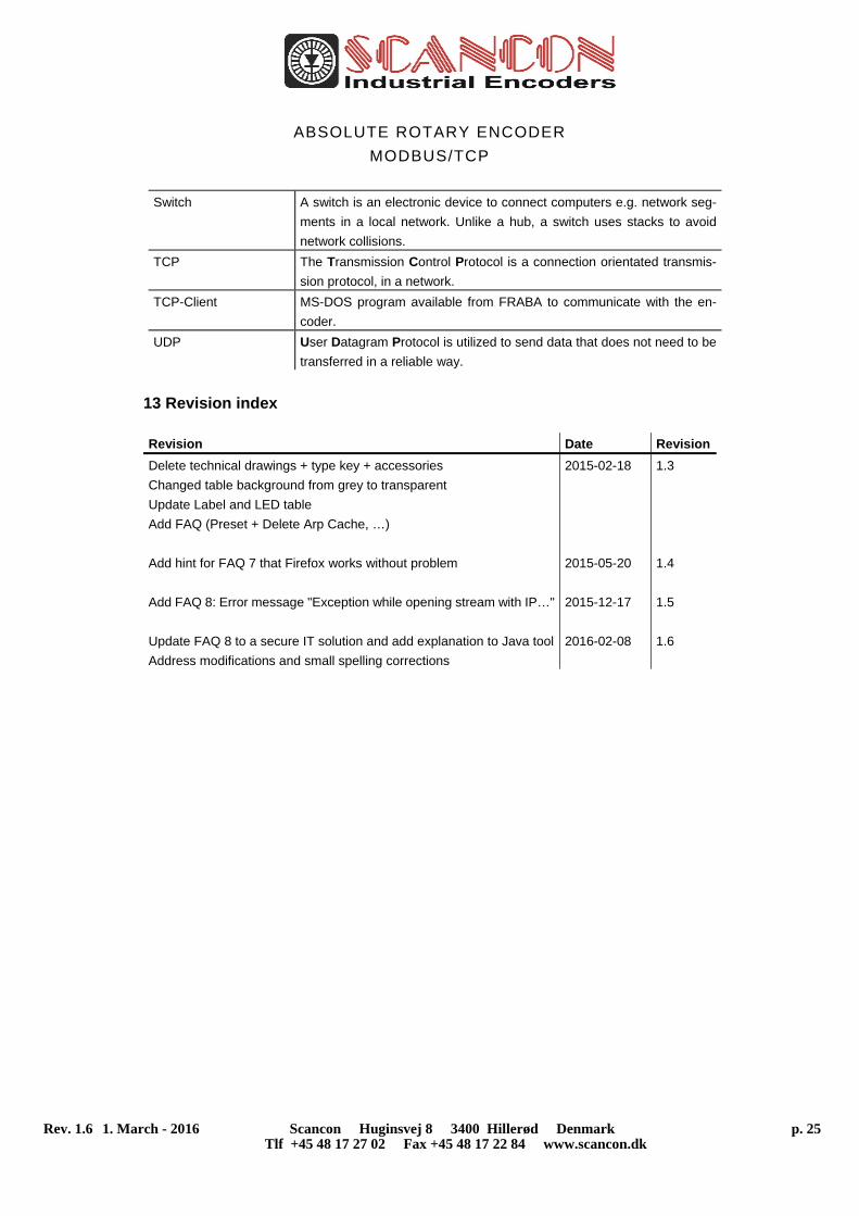
Switch A switch is an electronic device to connect computers e.g. network seg-
ments in a local network. Unlike a hub, a switch uses stacks to avoid
network collisions.
TCP The Transmission Control Protocol is a connection orientated transmis-
sion protocol, in a network.
TCP-Client MS-DOS program available from FRABA to communicate with the en-
coder.
UDP User Datagram Protocol is utilized to send data that does not need to be
transferred in a reliable way.
13 Revision index
Revision Date Revision
Delete technical drawings + type key + accessories
Changed table background from grey to transparent
Update Label and LED table
Add FAQ (Preset + Delete Arp Cache, …)
Add hint for FAQ 7 that Firefox works without problem
Add FAQ 8: Error message "Exception while opening stream with IP…"
Update FAQ 8 to a secure IT solution and add explanation to Java tool
Address modifications and small spelling corrections
2015-02-18
2015-05-20
2015-12-17
2016-02-08
1.3
1.4
1.5
1.6