Embed Size (px)
Citation preview
Pacific Aviation Investment Program
(PAIP)
Ministry of Communications, Transport
and Tourism Development
5 March 2013
Obstacle Limitation Surface (OLS) Survey and Type A Chart
Cassidy International Airport (CXI) - Kiribati (D-V2-1)
AECOM
Pacific Aviation Investment Program (PAIP)
Obstacle Limitation Surface (OLS) Survey and Type A Chart - Cassidy International
Airport (CXI) - Kiribati (D-V2-1)
5 March 2013
Obstacle Limitation Surface (OLS) Survey and Type A Chart
Cassidy International Airport (CXI) - Kiribati (D-V2-1)
MCTTD/CFLS/ATK-A14
Prepared for
Ministry of Communications, Transport and Tourism Development
Prepared by
AECOM New Zealand Limited
8 Mahuhu Crescent, Auckland 1010, PO Box 4241, Auckland 1140, New Zealand
T +64 9 967 9200 F +64 9 967 9201 www.aecom.com
5 March 2013
60277003
AECOM in Australia and New Zealand is certified to the latest version of ISO9001 and ISO14001.

AECOM
Pacific Aviation Investment Program (PAIP)
Obstacle Limitation Surface (OLS) Survey and Type A Chart - Cassidy International
Airport (CXI) - Kiribati (D-V2-1)
5 March 2013
Quality Information
Document Obstacle Limitation Surface (OLS) Survey and Type A Chart
Ref
60277003
k:\_projects\atta paip airports (60277003 60277004 60277008)\6. draft docs\6.1
reports\ols reports\kiribati\cassidy\ols report kiritimati cxi - rev a.docx
Date 5 March 2013
Prepared by Mike McWilliams
Reviewed by Craig Ridgley
Revision History
Revision Revision
Date Details
Authorised
Name/Position Signature
A 5-Mar-2013 For Client Review Craig Ridgley
Aviation Director

AECOM
Pacific Aviation Investment Program (PAIP)
Obstacle Limitation Surface (OLS) Survey and Type A Chart - Cassidy International
Airport (CXI) - Kiribati (D-V2-1)
5 March 2013
Table of Contents
Glossary i Executive Summary ii
Update AIP Data ii Type A Charts and Obstruction Data Sheets iii Approach OLS Plan and Section views and data sheets iii Obstruction Clearance Works iii
1.0 Introduction 1 1.1 Terms of Reference 1 1.2 Scope of Services – extracted from TOR 1
2.0 Survey Methodology 3 2.1 Technical References 3 2.2 Field Survey 3 2.3 Data Processing 3
3.0 Aerodrome Data 5 3.1 Aerodrome Reference Point – ARP 5 3.2 Runway End Points 5 3.3 Runway Declared Distances 6 3.4 Runway Strip and RESA Dimensions 6 3.5 Magnetic Declination 7 3.6 Altimeter Check Location 7 3.7 Navigational Aids Locations 7 3.8 Tall Masts 8
4.0 Obstacle Limitation Surfaces 11 4.1 Limitation Surfaces Details 11 4.2 Type A Charts 12
5.0 Type A Chart Tables 13 5.1 Take-Off Obstacles Departure Runway 08 13 5.2 Take Off Obstacles Departure Runway 26 14
6.0 Approach Obstacles 15 6.1 Runway 08 Approach 15 6.2 Runway 26 Approach 16
Appendix A Survey Records A
Appendix B ICAO Type A chart and data tables B
Appendix C Approach OLS chart and data tables C

AECOM
Pacific Aviation Investment Program (PAIP)
Obstacle Limitation Surface (OLS) Survey and Type A Chart - Cassidy International
Airport (CXI) - Kiribati (D-V2-1)
5 March 2013
i
Glossary
AC Advisory Circular
AIP Aeronautical Information Publication
ARP Aerodrome Reference Point
ASDA Accelerated Stop Distance Available
ATC Air Traffic Control
ATCT Air Traffic Control Tower
DME Distance Measuring Equipment
GPS Global Positioning System
ICAO International Civil Aviation Organization
ISO International Organization for Standardization
ITRF International Terrestrial Reference System
km Kilometres
LDA Landing Distance Available
m Metre
mm Millimetres
NDB Non-directional Beacon
NZCAA New Zealand Civil Aviation Authority
OLS Obstacle Limitation Surface
PAIP Pacific Aviation Investment Program
PAPI Precision Approach Path Indicator
RESA Runway End Safety Area
SARP Standards and Recommended Practices
TODA Take Off Distance Available
TORA Take Off Run Available

AECOM
Pacific Aviation Investment Program (PAIP)
Obstacle Limitation Surface (OLS) Survey and Type A Chart - Cassidy International
Airport (CXI) - Kiribati (D-V2-1)
5 March 2013
ii
Executive Summary
AECOM have completed the Obstacle Limitation Surface (OLS) survey for Cassidy International Airport (CXI) and
have compiled the Type A charts for the take-off climb surface for departure runways 08 and 26 to both ICAO
geometric standards.
The departure take-off climb surface is normally the critical performance consideration for aircraft operations.
The aircraft has to accelerate from a standstill to take-off speed then climb out over potential obstacles past the
end of the runway strip. In comparison, on approach the aircraft overflies potential obstructions on its way to
touching down on the runway (part way along the runway surface). On the aircraft approach, issue with regards to
strip width are an important consideration.
The Type A chart is intended to advise both aircraft operators and the Airport Authority of potential take-off flight
path obstructions which may impact on the aircraft performance considerations, and depending on the location
and height of the obstruction these may also need to be notified in the Aeronautical Information Publication (AIP)
for the airport. The Type A chart is also used by the airport operator to actively manage obstructions, such as
trees which increase in height over time, and to limit the height of future construction works to be below the critical
surface levels.
The AIP also provides a table which relates to the runway length available in relationship to the take-off and
approach surfaces. This allows pilots to gauge if terrain obstructions are occurring. The existing published table
will require significant amendment if the observed obstructions are not attended to.
The OLS survey also considers and presents the aircraft arrival profile, the runway strip and runway strip
transitional side slope profiles. AECOM have prepared a separate approach – runway strip OLS plan for
Cassidy. This is necessary as it provides additional information required to be considered in the overall aircraft
flight envelope from an operational safety perspective.
Currently clearways are provided at each runway end, this makes the departure slope clearance significantly
more onerous than the approach path. Having clearways allows heavier departure take-off weights to be
achieved from Cassidy’s runway length.
Due to the predominant wind orientation, runway operations are typically approach to and departure from runway
08. Aircraft typically makes land fall over London town and overfly the atolls terrain immediately to the west of
the 08 runway on approach and departs out over the sea when climbing away from the 26 threshold.
Update AIP Data
The established positions and heights (feet amsl) for the main AIP references points for the runway are as follows:
Updated Data for Aeronautical Information Publication (AIP)
Point ID Latitude Longitude Height (ft)
ARP 1° 59’11.661” N 157° 21’06.890” W 9.4
TH08 1 59’10.580” N 157 21’ .712” W 7.6
TH26 1 59’10.566” N 157 20’25.662” W 8.4
NDB mast 1°59'00.32" N 157°21'18.36" W 71.2
NDB mast 1°59'00.30" N 157°21'17.28" W 56.7
DME mast 1°58'59.84" N 157°21'15.90" W 66.3
Communications mast 1°58'57.12" 157°21'10.88" 116.8
Communications mast 1°59'02.57" 157°21'56.97" 123.4
Communications mast – satellite tracking station 2°02'41.26" 157°26'44.86" 135.8
Communications mast – Government buildings 1°59'19.97" 157°28'43.30" 149.8
This information should be provided to Airways International for inclusion into future AIP updates.
AECOM
Pacific Aviation Investment Program (PAIP)
Obstacle Limitation Surface (OLS) Survey and Type A Chart - Cassidy International
Airport (CXI) - Kiribati (D-V2-1)
5 March 2013
iii
Type A Charts and Obstruction Data Sheets
The Type A charts and obstruction data tables are attached in Appendix B.
Approach OLS Plan and Section views and data sheets
The Approach OLS charts and obstruction data tables are attached in Appendix C.
Obstruction Clearance Works
We recommend that palm tree obstructions are removed and other vegetation is cut back to the 1.6% gradient
limitation for both runways.
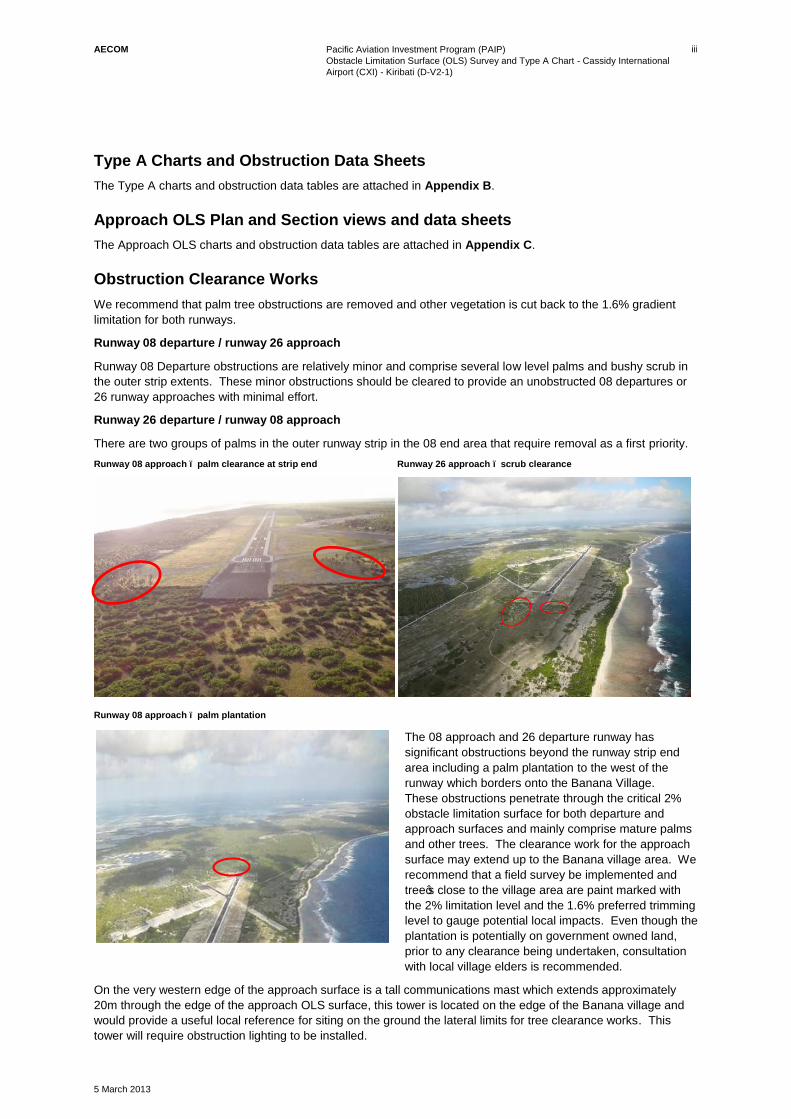
Runway 08 departure / runway 26 approach
Runway 08 Departure obstructions are relatively minor and comprise several low level palms and bushy scrub in
the outer strip extents. These minor obstructions should be cleared to provide an unobstructed 08 departures or
26 runway approaches with minimal effort.
Runway 26 departure / runway 08 approach
There are two groups of palms in the outer runway strip in the 08 end area that require removal as a first priority.
Runway 08 approach – palm clearance at strip end Runway 26 approach – scrub clearance
Runway 08 approach – palm plantation
The 08 approach and 26 departure runway has
significant obstructions beyond the runway strip end
area including a palm plantation to the west of the
runway which borders onto the Banana Village.
These obstructions penetrate through the critical 2%
obstacle limitation surface for both departure and
approach surfaces and mainly comprise mature palms
and other trees. The clearance work for the approach
surface may extend up to the Banana village area. We
recommend that a field survey be implemented and
tree’s close to the village area are paint marked with
the 2% limitation level and the 1.6% preferred trimming
level to gauge potential local impacts. Even though the
plantation is potentially on government owned land,
prior to any clearance being undertaken, consultation
with local village elders is recommended.
On the very western edge of the approach surface is a tall communications mast which extends approximately
20m through the edge of the approach OLS surface, this tower is located on the edge of the Banana village and
would provide a useful local reference for siting on the ground the lateral limits for tree clearance works. This
tower will require obstruction lighting to be installed.

AECOM
Pacific Aviation Investment Program (PAIP)
Obstacle Limitation Surface (OLS) Survey and Type A Chart - Cassidy International
Airport (CXI) - Kiribati (D-V2-1)
5 March 2013
iv
Recommended Next Steps
In summary the following actions are recommended:
1) The runway ends, ARP and Navigational aids details are to be provided to Airways International for updating
in the AIP publication data.
2) A number of additional tall masts have been identified and should also be added onto the AIP charts via
Airways Internationals AIP publication service.
3) Two groups of trees located in the outer extents of the runway strip at the 08 end area are required to be
removed as soon as practical.
4) The 08 Departure runway is the predominant take-off operation. There are close in scrub and tree
obstructions at the 26 runway end. We recommend that these palm and scrub obstructions be removed as
soon as possible; this should be a relatively simple clearance exercise. Once this clearance is completed,
the Type A Chart can be updated for the 08 departure runway as being obstruction free.
5) A more rigorous tree clearance program is required for the 26 departures / 08 approach runway:
a) This will include removal of a significant number of plantation trees to the west of the 08 runway end
and may encroach up to the Banana village area.
b) Whilst this plantation is located on Government land, consultation with the local Banana village
representatives is recommended.
c) A field survey to mark trees with the required clearance levels adjacent to the village is recommended
to gauge potential impacts of the proposed clearance works.
6) Once the tree clearance work has been completed on both runway ends, a check survey should be
implemented and a revised type A chart then issued for formal publication.
7) Once the Type A chart is published there is an obligation to resurvey every 3 to 5 years to monitor tree
growth, check for new obstructions and actively maintain obstruction clearances.

AECOM
Pacific Aviation Investment Program (PAIP)
Obstacle Limitation Surface (OLS) Survey and Type A Chart - Cassidy International
Airport (CXI) - Kiribati (D-V2-1)
5 March 2013
1
1.0 Introduction
1.1 Terms of Reference
In accordance with the PAIP development objective to improve aviation infrastructure safety and security
compliance, it is expected that the participating airports will undergo aerodrome certification as a result of the
improvements financed under PAIP.
Safety oversight for each participating country is conducted in accordance with the New Zealand Civil Aviation
Rules (NZCARs) and accordingly, this study is required in order that each aerodrome may comply with the
requirements of NZCAR Part 139.51 and part 139.125 as reproduced below1:
NZCAR 139.51 Aerodrome design requirements
a) An applicant for the grant of an aerodrome operating certificate must ensure that the physical characteristics
of the aerodrome; the obstacle limitation surfaces; the visual aids for navigation and for denoting obstacles
and restricted areas; and the equipment and installations for the aerodrome are commensurate with the
following:
1) The characteristics of the aircraft that the aerodrome is intended to serve.
2) The lowest meteorological minima intended for each runway.
3) The ambient light conditions intended for the operation of aircraft.
NZCAR 139.125 Unsafe Conditions
a) Each holder of an aerodrome operating certificate shall establish procedures for restricting aircraft
operations where an unsafe condition exists on an aerodrome.
b) The procedures shall ensure that operations are not conducted on portions of the aerodrome where such an
unsafe condition exists.
Aerodromes in Kiribati and Tuvalu will be expected to undergo aerodrome certification as a result of the PAIP
investments, including undertaking an OLS study and design of GNSS approaches. Tonga has recently
completed an OLS with associated GNSS approaches, and is currently certified against the Tongan equivalent of
NZCAR Part 139, however Kiribati and Tuvalu have not yet gone through this certification process.
OLS surveys, Analysis of Requirements and GNSS approaches are required for all aerodromes participating in
PAIP. Some airports have had some work undertaken already but not all airports require the same scope of
services. Partial OLS and RNAV approaches have been conducted at Bonriki International Airport in Kiribati, and
an OLS and RNAV approach has been undertaken at Funafuti International Airport in Tuvalu. These shall be
reviewed and expanded upon as necessary, as part of this assignment.
The Republic of Kiribati and Tuvalu follow the standards, recommended practises and procedures that have been
adopted by ICAO. As such, ICAO Procedures for Air Navigation Services — Aircraft Operations (PANS-OPS, Doc
8168) Volume II, Part 1, Section 2, Chapter 4, Quality Assurance), requires that the State take measures to
“control” the quality of the processes associated with the construction and review/quality assurance of instrument
flight procedures. Review of each instrument procedure will be required as part of this assignment.
1.2 Scope of Services – extracted from TOR
The detailed scope of services to be provided shall be undertaken at each participating airport: Cassidy
International Airport (Kiribati), Bonriki International Airport (Kiribati), and Funafuti International Airport (Tuvalu), as
indicated and shall include:-
Part A – Obstacle Limitation Survey
a) Review of existing OLS, RNAV, GPS and GNSS Approaches for Bonriki International Airport, Kiribati, and
Funafuti International Airport, Tuvalu.
1 National legislation exists in each country based on the NZCARs. This assignment shall be conducted against the domestic
equivalent of these NZCARs.

AECOM
Pacific Aviation Investment Program (PAIP)
Obstacle Limitation Surface (OLS) Survey and Type A Chart - Cassidy International
Airport (CXI) - Kiribati (D-V2-1)
5 March 2013
2
b) Undertake an Obstacle Limitation Survey (OLS) in consideration of the current operational and design
aircraft for each aerodrome. This shall include development, or review and updating of existing information
as applicable:
i) Convert all aeronautical geographical coordinates into the WGS-84 geodetic reference datum.
ii) Establish an Aerodrome Reference Point (ARP) in WGS-84.
iii) Establish runway ends, threshold points for each runway, in WGS-84 and elevations.
iv) Establish runway length and declared distances.
v) Establish runway strip dimensions and options for RESA.
vi) Establish Runway Direction and Magnetic Declination.
vii) Establish positions and heights of all obstacles infringing the appropriate OLS for each aerodrome as
required under ICAO Annex 14 (that includes obstacle penetration through the visual slope segment of
runways’ approaches).
viii) Produce an Aerodrome Obstacle Chart – ICAO Type A (Operating Limitations).
ix) Establish pre-flight altimeter check location at apron.
x) Establish location, coordinates and height of air navigation aids.
Part B – Analysis of Requirements for Operating and Design Aircraft, and Development of Supporting
Material
a) Based on the OLS survey and activities undertaken in Part A of this assignment, prepare an Analysis of
Requirements for the operating and design aircraft for each aerodrome taking into consideration compliance
issues with ICAO Annex 14, and NZCAR Part 139.
b) Identify issues arising from the Analysis above.
c) Develop risk mitigation measures to address the Analysis and identified Issues per (a) and (b) above.
d) Develop supporting documentation such as ICAO Type A charts, topographical charts etc for each
aerodrome.
e) As part of “control of the quality of the process” a review of each instrument procedure at the Cassidy,
Bonriki and Funafuti Airports is to be completed. This will involve:
i) a complete planned systemic review according to ICAO standards and recommended practises on the
existing airspace procedures.
ii) review of all instrument procedures at the airports above, following and adhering to all ICAO
practises/guidelines to include (but not limited to) all procedure design processes reviewed against
PANSOP’s criteria changes to ensure compliance, updated with new obstacle/surveyed data, terrain,
procedure design documentation, calculations, verification and validation methods, safety and
efficiency recommendations, any deficiencies noted and qualify the acquisition/processing of source
information/data.
There are 4 procedures for each airport to be reviewed and reported on (12 procedures in total to be
reviewed) plus likely updates to each of the three airports published data as a result of the review findings
and recommendations.
f) Develop a full Procedure Design Report (PDR) will be issued outlining the results of the airspace procedure
review in part (e) above.
In undertaking this assignment, the Consultant will be expected to review existing OLS, RNAV, GPS and GNSS
Approaches for Bonriki International Airport, Kiribati, and Funafuti International Airport, Tuvalu.
In addition, the Consultant will be directed by the relevant government airport operator, and will be expected to
liaise closely with relevant stakeholders, such as the airlines currently servicing the airports.

AECOM
Pacific Aviation Investment Program (PAIP)
Obstacle Limitation Surface (OLS) Survey and Type A Chart - Cassidy International
Airport (CXI) - Kiribati (D-V2-1)
5 March 2013
3
2.0 Survey Methodology
2.1 Technical References
The OLS survey and related Type A chart preparation has been undertaken in accordance with the following
technical references:
New Zealand Civil Aviation Authority Advisory Circulars – (NZAC)
AC 139-06 Aerodrome Design Requirements
AC 139-09 Notification of Aerodrome Data and Information
AC 139-10 Control or Obstacles
AC 173-1 Instrument Flight Procedures Design
New Zealand Civil Aviation Authority Rules (NZCAR), specifically:
CAR 139.51 Aerodrome Design Requirements
CAR 139.125 Unsafe Conditions
International Civil Aviation Organisation (ICAO)
Annex 14 Aerodromes Volume 1
DOC 8168-OPS Aircraft Operations
Volume III Construction of Visual and Instrument flight Procedure
2.2 Field Survey
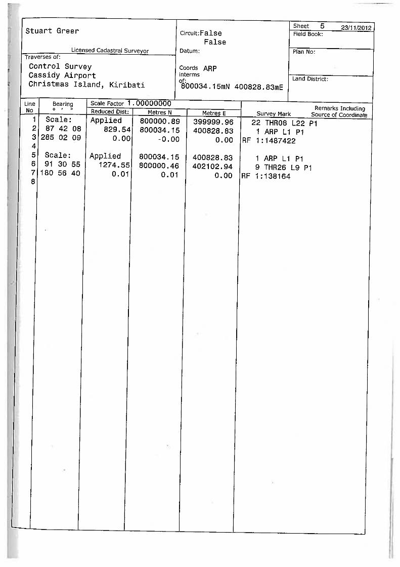
A field survey was conducted from 1st to 7
th November 2012 by Mr Stuart Greer and Mr Suvenia Hasiata of
WOODS Surveyors.
The survey was carried out using the following equipment:
Total Station: Leica TCRP1203+R400, S/N 262822
Dgital Level: Leica DNA03, S/N 332837 (Hired)
GPS Reciever: Controller: RX1250X, S/N 308995
Antenna: ATX1230GG, S/N 187206
Radio Cradle: GHT56, S/N 108867
Radio: PDLGFU15-2 S/N 08210511
Six hour static GPS observations were taken at runway threshold (TH) 08, TH26 and the Aerodrome Reference
Point (ARP). This provided Latitude, Longitude and Elliptical height
Conventional traversing methods were used to locate the positions of existing and any additional control marks
that were required for the survey.
Full transcripts and methodology can be found in the WOODS Topographical Survey Report located in Appendix
A.
The height at the Aerodrome Reference Point (ARP) corresponding to the local height datum was used for all
recorded orthometric heights. This height information was provided by the Government of Kiribati Survey office to
AECOM as part of the recent runway upgrade project.
2.3 Data Processing
All data processing was conducted and verified by WOODS surveyor. AutoCAD/PDF format drawings and a
survey report were provided to AECOM.

AECOM
Pacific Aviation Investment Program (PAIP)
Obstacle Limitation Surface (OLS) Survey and Type A Chart - Cassidy International
Airport (CXI) - Kiribati (D-V2-1)
5 March 2013
4
AECOM constructed an OLS for both the approach surfaces and departure surfaces for both 1.2% and 1.6%.
Three dimensional Triangulated Irregular Network (TIN) models were constructed using Bentley MX software and
checked by an aviation engineer using separate 12D Model 9 software.
All additional data has been calculated by engineers using AutoCAD and Microsoft Excel software.
The Type A take-off runway obstacle data for both runways is presented in Appendix B.
OLS data for the approach runway and runway strip transitional surfaces are attached in Appendix C.

AECOM
Pacific Aviation Investment Program (PAIP)
Obstacle Limitation Surface (OLS) Survey and Type A Chart - Cassidy International
Airport (CXI) - Kiribati (D-V2-1)
5 March 2013
5
3.0 Aerodrome Data
3.1 Aerodrome Reference Point – ARP
Aerodrome Reference Point (ARP) is the declared position of the airport which is then used to calculate specific
components of the runway OLS. The position of the ARP is provided in the AIP.
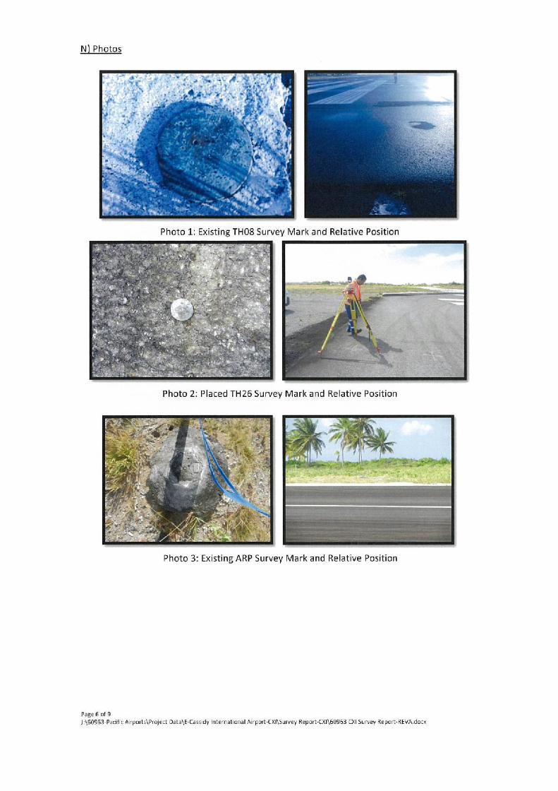
The ARP at Cassidy International Airport consists of a tube set in concrete with a marker pin and is located in the
northern flank of the runway strip around the mid runway distance.
Figure 3-1 Close up of the ARP benchmark Figure 3-2 Location of the ARP benchmark relative to the runway
Table 3.1 shows the position of the ARP in WGS84 coordinates and ellipsoidal heights calculated using GPS
observations. The orthometric height is calculated through a level survey linking the ARP and Runway End Points
to the local survey Benchmarks at the airport.
Table 3.1 ARP
Point Name Latitude Longitude Ellipsoidal Height
(m) Orthometric Height
ARP 1° 59’11.661” N 157° 21’06.890” W 24.099 2.860
The current ARP is published as the mid runway point, and listed as 1° 59’28” N 157° 21’ 1” W, this will need to
be updated with the information in Table 3.1.
3.2 Runway End Points
Table 3.2 shows the position of the runway threshold end points in WGS84 coordinates and ellipsoidal heights
calculated using GPS observations. The orthometric height is calculated through a level survey linking the ARP
and Runway End Points to the local survey Benchmarks at the airport.
Table 3.2 Runway End Points
Point Name Latitude Longitude Ellipsoidal Height
(m)
Orthometric Height
(m)
TH08 1 59’10.580” N 157 21’ .712” W 23.637 2.311
TH26 1 59’10.566” N 157 20’25.662” W 23.731 2.550
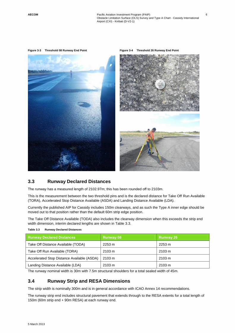
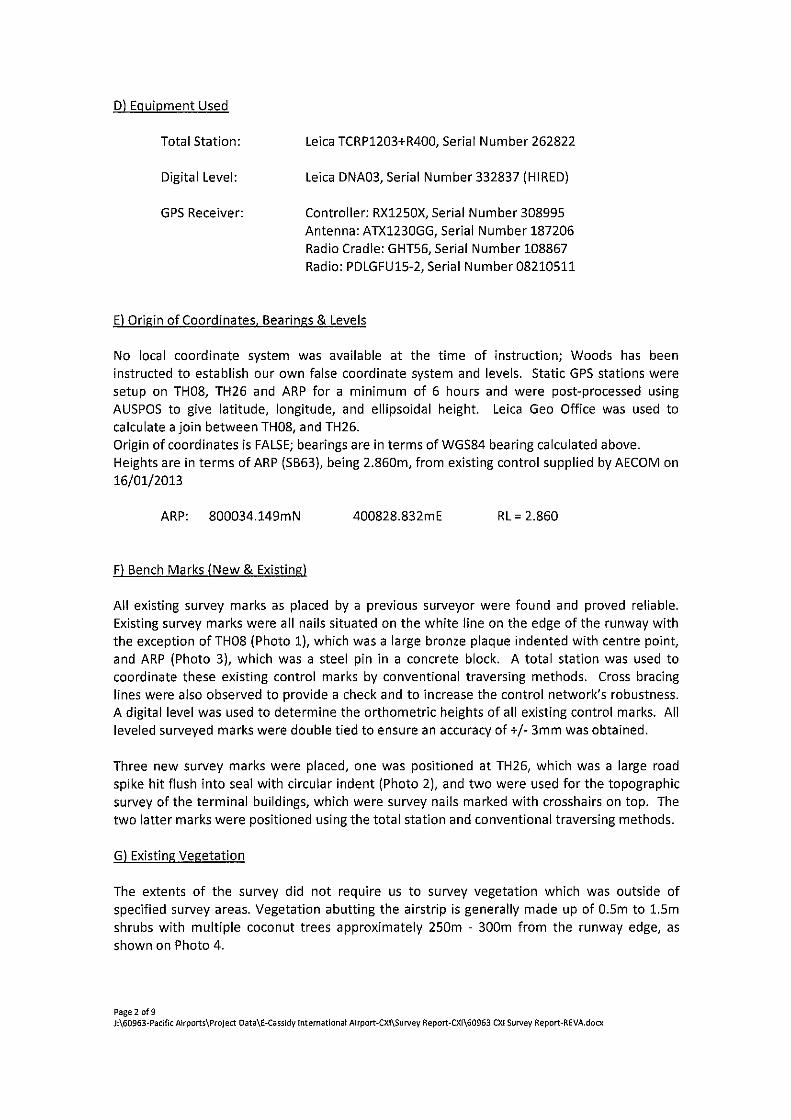
Threshold 08 has a bronze plaque indented with a centre point, refer Figure 3-3.
A new Survey pin was established for the 26 Threshold, refer Figure 3-4.
AECOM
Pacific Aviation Investment Program (PAIP)
Obstacle Limitation Surface (OLS) Survey and Type A Chart - Cassidy International
Airport (CXI) - Kiribati (D-V2-1)
5 March 2013
6
Figure 3-3 Threshold 08 Runway End Point
Figure 3-4 Threshold 26 Runway End Point
3.3 Runway Declared Distances
The runway has a measured length of 2102.97m; this has been rounded off to 2103m.
This is the measurement between the two threshold pins and is the declared distance for Take Off Run Available
(TORA), Accelerated Stop Distance Available (ASDA) and Landing Distance Available (LDA).
Currently the published AIP for Cassidy includes 150m clearways, and as such the Type A inner edge should be
moved out to that position rather than the default 60m strip edge position.
The Take Off Distance Available (TODA) also includes the clearway dimension when this exceeds the strip end
width dimension, interim declared lengths are shown in Table 3.3.
Table 3.3 Runway Declared Distances
Runway Declared Distances Runway 08 Runway 26
Take Off Distance Available (TODA) 2253 m 2253 m
Take Off Run Available (TORA) 2103 m 2103 m
Accelerated Stop Distance Available (ASDA) 2103 m 2103 m
Landing Distance Available (LDA) 2103 m 2103 m
The runway nominal width is 30m with 7.5m structural shoulders for a total sealed width of 45m.
3.4 Runway Strip and RESA Dimensions
The strip width is nominally 300m and is in general accordance with ICAO Annex 14 recommendations.
The runway strip end includes structural pavement that extends through to the RESA extents for a total length of
150m (60m strip end + 90m RESA) at each runway end.
AECOM
Pacific Aviation Investment Program (PAIP)
Obstacle Limitation Surface (OLS) Survey and Type A Chart - Cassidy International
Airport (CXI) - Kiribati (D-V2-1)
5 March 2013
7
3.5 Magnetic Declination
http://www.ga.gov.au/oracle/geomag/agrfform.jsp
Australian Geomagnetic Reference Field Computation
Requested: Latitude 1o 59' 12", Longitude -157o 21' 07", Elevation 0 km, Date 2013/01/30
Calculated: Latitude +1.9867o, Longitude -157.3519o, Elevation 0.00 km, Epoch 2013.0795
Location is outside the AGRF area. A global field model has been used
Magnetic Field Components
D = 9.021 deg
dD = 0.008 deg/yr
http://www.ngdc.noaa.gov/geomag-web/#declination
##################################################
# Declination Values CXI ##################################################
# 5 Fields: # (1) Date in decimal years
# (2) Latitude in decimal degrees # (3) Longitude in decimal degrees # (4) Declination in decimal degrees # (5) Change in declination in decimal minutes / year
# # Magnetic Model: IGRF
# Elevation: 0.00000 km ##################################################
2013.077 1.9866 -157.352 9.02114 0.45965
3.6 Altimeter Check Location
Existing altimeter checks are located at each runway threshold and are set at 5ft. Actual levels, rounded to the
nearest foot are:
- Runway 08: 8 ft
- Runway 26: 8 ft
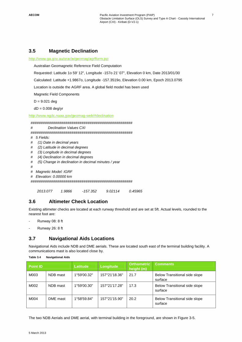
3.7 Navigational Aids Locations
Navigational Aids include NDB and DME aerials. These are located south east of the terminal building facility. A
communications mast is also located close by.
Table 3.4 Navigational Aids
Point ID Latitude Longitude Orthometric
height (m)
Comments
M003 NDB mast 1°59'00.32" 157°21'18.36" 21.7 Below Transitional side slope
surface
M002 NDB mast 1°59'00.30" 157°21'17.28" 17.3 Below Transitional side slope
surface
M004 DME mast 1°58'59.84" 157°21'15.90" 20.2 Below Transitional side slope
surface
The two NDB Aerials and DME aerial, with terminal building in the foreground, are shown in Figure 3-5.
AECOM
Pacific Aviation Investment Program (PAIP)
Obstacle Limitation Surface (OLS) Survey and Type A Chart - Cassidy International
Airport (CXI) - Kiribati (D-V2-1)
5 March 2013
8
Figure 3-5 DNE mast (left) and NDB masts (centre and right)
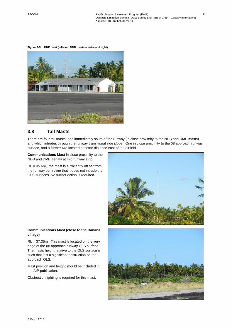
3.8 Tall Masts
There are four tall masts, one immediately south of the runway (in close proximity to the NDB and DME masts)
and which intrudes through the runway transitional side slope. One in close proximity to the 08 approach runway
surface, and a further two located at some distance east of the airfield.
Communications Mast in close proximity to the
NDB and DME aerials at mid runway strip
RL = 35.6m, the mast is sufficiently off set from
the runway centreline that it does not intrude the
OLS surfaces. No further action is required.
Communications Mast (close to the Banana
village)
RL = 37.35m. This mast is located on the very
edge of the 08 approach runway OLS surface.
The masts height relative to the OLS surface is
such that it is a significant obstruction on the
approach OLS.
Mast position and height should be included in
the AIP publication.
Obstruction lighting is required for this mast.

AECOM
Pacific Aviation Investment Program (PAIP)
Obstacle Limitation Surface (OLS) Survey and Type A Chart - Cassidy International
Airport (CXI) - Kiribati (D-V2-1)
5 March 2013
9
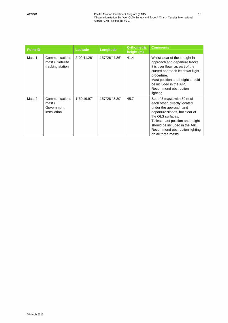
Satellite Tracking Station Communications
Mast
Obstacle Reduced Level = 41.38m
This mast is outside the aircraft approach and
departures tracks. Apart from updating the AIP
information, no other action is required.
Given the mast height obstruction lighting is
recommended, this will need to be coordinated
with the private owner of this facility.
Government Telecommunications tower
(opposite the main government buildings
enroute to London town )
Comprises three masts, tallest obstacle
Reduced Level = 45.67m
These masts are positioned on the approach
and departure centreline, but below the
approach and departure surfaces. The mast is
close to the inner horizontal height RL = 48.9m
and as such would benefit from the fitting of
obstruction lighting pending further inputs from
airlines and air navigational reviews.
Tallest mast position and height should be
included in the AIP, lighting of this set of masts
is recommended.
Summarised AIP information for the tall masts are presented in Table 3.5.
Table 3.5 Tall Masts data for AIP Publications
Point ID Latitude Longitude Orthometric
height (m)
Comments
M000 Communications
Mast
1°58'57.12" 157°21'10.86" 35.6 Below runway side slope OLS
surface
M001 Communications
Mast
1°59'02.57" 157°21'56.97" 37.6 Clear of type A departure
surface but significantly
infringes the edge of the wider
ICAO approach Surface.
Mast position and height should
be included in the AIP
publication. Obstruction lighting
is required for this mast.
AECOM
Pacific Aviation Investment Program (PAIP)
Obstacle Limitation Surface (OLS) Survey and Type A Chart - Cassidy International
Airport (CXI) - Kiribati (D-V2-1)
5 March 2013
10
Point ID Latitude Longitude Orthometric
height (m)
Comments
Mast 1 Communications
mast – Satellite
tracking station
2°02'41.26" 157°26'44.86" 41.4 Whilst clear of the straight in
approach and departure tracks
it is over flown as part of the
curved approach let down flight
procedure.
Mast position and height should
be included in the AIP.
Recommend obstruction
lighting.
Mast 2 Communications
mast –
Government
installation
1°59'19.97" 157°28'43.30" 45.7
Set of 3 masts with 30 m of
each other, directly located
under the approach and
departure slopes, but clear of
the OLS surfaces.
Tallest mast position and height
should be included in the AIP.
Recommend obstruction lighting
on all three masts.

AECOM
Pacific Aviation Investment Program (PAIP)
Obstacle Limitation Surface (OLS) Survey and Type A Chart - Cassidy International
Airport (CXI) - Kiribati (D-V2-1)
5 March 2013
11
4.0 Obstacle Limitation Surfaces
4.1 Limitation Surfaces Details
OLS are theoretical boundaries surrounding a runway that provide a safe passage for aircraft to operate. There
are two main parts of OLS: approach/departure slopes which consist of slopes starting at the end of the runway
strip (otherwise known as the inner edge) and transitional surfaces extend up from the edge of the runway strip
until meeting the horizontal surface and conical surfaces. Refer Figure 4-1 for a cut through diagram showing the
various surfaces.
Figure 4-1 Obstacle Limitation Surface
For the approach OLS, the following dimensions and slopes have been adopted:
Table 4.1 Runway Approach OLS dimensions and slopes
Surface Measurement type ICAO Table 4-1 AC139-06 Table 4-1
Conical Slope 5% (=1:20) 1:20
Height above ARP 45 m + 75m 150 m
Inner Horizontal Height above ARP 45 m 45 m
Locus from strip edge 4000 4000
Approach Width (inner edge) 300m 150 / 300m
Distance from Threshold 60 m 60 m
Divergence each side 15% (=1:6.6) 1:6.6
Length 15,000m 15,000m
Slope 2% (=1:50) 1:50
Transitional Slope 14.3% (=1:7) 1:7
As can be seen, there is a variance in the height of the upper conical surface between ICAO and NZ CAA
advisory (120m vs 150m). For the upper conical OLS surfaces, we have assumed the more onerous NZCAA
height requirement.
The NZ Advisory Circular does allow consideration of a 150m inner edge width. Given the international
emergency alternate status of CXI, AECOM have presented the more onerous 300m approach width profile for
the approach OLS.

AECOM
Pacific Aviation Investment Program (PAIP)
Obstacle Limitation Surface (OLS) Survey and Type A Chart - Cassidy International
Airport (CXI) - Kiribati (D-V2-1)
5 March 2013
12
The take-off surfaces utilise the dimensions and slopes detailed in Table 4.2, as can be seen both ICAO and NZ
CAA requirements are identical in this instance.
Table 4.2 Take-off Dimensions and Slopes
Measurement type ICAO Table 4-2 AC139-06 Table 4-2
Code 3 or 4 Code 3 or 4
Length of inner edge 180m 180m
Distance from runway end 60m* 60m
Divergence each side 12.5% 1:8 (=12.5%)
Final Width 1200m
1800m**
1200m
1800m**
Length 15,000m 15,000m
Slope 2% 2%
*At CXI a 150m clearway is currently published in the AIP, this moves the inner edge position to 150m past the runway
threshold point.
**1800m when the intended track includes changes of heading greater than 15º for operations conducted in IMC, VMC by night
Approach and take off surface configurations are shown in Figures 4-2 and 4-3.
Figure 4-2 Approach Area and Surface
Figure 4-3 Take-off Climb Area and Surface
4.2 Type A Charts
The Type A Chart requires obstacles above 1.2% to be recorded for an ongoing monitoring purposes. This is
especially important for trees which increase in height with time.
AECOM has added the 1.6% surface level into the Type A Tables for reference. Often, trees are trimmed back to
the 1.6% level in accordance with the recommendation presented in ICAO Annex 14, AC 139-06 and AC 139-10
for obstacle control. We note that palms, due to the growth point being at the crown, do not survive when topped.
Accordingly, palms should be cut back to ground level when these intrude into the OLS surfaces.
AECOM
Pacific Aviation Investment Program (PAIP)
Obstacle Limitation Surface (OLS) Survey and Type A Chart - Cassidy International
Airport (CXI) - Kiribati (D-V2-1)
5 March 2013
13
5.0 Type A Chart Tables
Since CXI has runway end clearways, the departure slope obstacle clearances are more onerous than the
approach OLS slope profile.
Due to the prevalent wind direction being westward, the primary approach and departures are on the 08 runway
for the vast majority of flight operations.
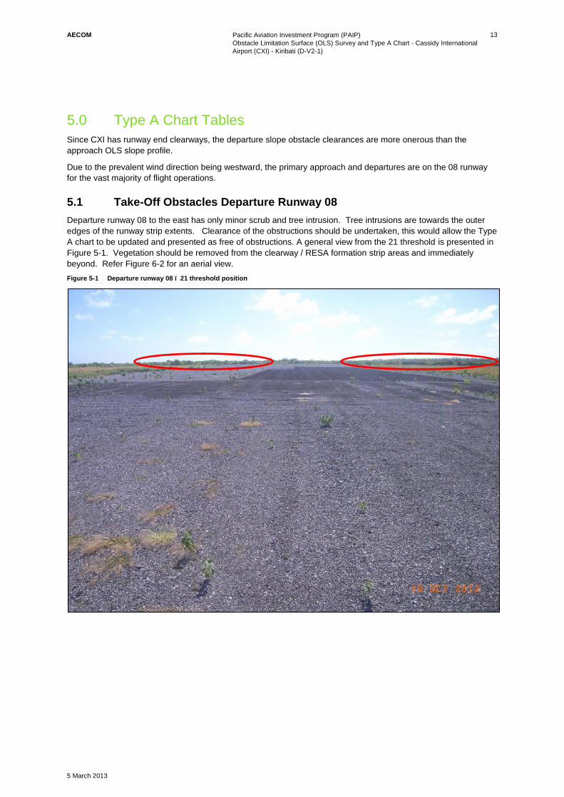
5.1 Take-Off Obstacles Departure Runway 08
Departure runway 08 to the east has only minor scrub and tree intrusion. Tree intrusions are towards the outer
edges of the runway strip extents. Clearance of the obstructions should be undertaken, this would allow the Type
A chart to be updated and presented as free of obstructions. A general view from the 21 threshold is presented in
Figure 5-1. Vegetation should be removed from the clearway / RESA formation strip areas and immediately
beyond. Refer Figure 6-2 for an aerial view.
Figure 5-1 Departure runway 08 – 21 threshold position

AECOM
Pacific Aviation Investment Program (PAIP)
Obstacle Limitation Surface (OLS) Survey and Type A Chart - Cassidy International
Airport (CXI) - Kiribati (D-V2-1)
5 March 2013
14
5.2 Take Off Obstacles Departure Runway 26
There are a number of mature palm trees which are now an obstruction to the runway take-off surface. There is
a significant plantation to the west of the extended centreline as shown below. The tall tower observable denotes
the lateral edge of the wider approach path slope.
Figure 5-2 Runway 26 departure clearance

AECOM
Pacific Aviation Investment Program (PAIP)
Obstacle Limitation Surface (OLS) Survey and Type A Chart - Cassidy International
Airport (CXI) - Kiribati (D-V2-1)
5 March 2013
15
6.0 Approach Obstacles
6.1 Runway 08 Approach
In addition to the extensive clearance work needed in the palm plantation to the west of the runway, refer Figure
5-2,on approach to runway 08 there are a number of palm tree intrusions within the strip end area. These need
to be removed as a priority as soon as possible, refer Figure 6-1 for details.
Figure 6-1 08 approach runway – palms in outer extents of the runway end area

AECOM
Pacific Aviation Investment Program (PAIP)
Obstacle Limitation Surface (OLS) Survey and Type A Chart - Cassidy International
Airport (CXI) - Kiribati (D-V2-1)
5 March 2013
16
6.2 Runway 26 Approach
As can be seen from Figure 6-2, apart from minor low level scrub removal close to the runway strip end, there are
no significant obstructions to the runway 26 approach.
Figure 6-2 Runway 26 approach

AECOM
Pacific Aviation Investment Program (PAIP)
Obstacle Limitation Surface (OLS) Survey and Type A Chart - Cassidy International
Airport (CXI) - Kiribati (D-V2-1)
5 March 2013
Appendix A
Survey Records


175.50
93Á08'55"
186.99
89Á59'55"
167.37
89Á59'15"
179.52
90Á01'00"
171.95
89Á58'55"
176.19
90Á01'20"
151.30
90Á02'00"
6
9
.
8
0
1
1
0
Á
0
3
'4
5
"
6
9
.
4
5
2
4
9
Á
5
7
'1
0
"
126.04
270Á01'00"
191.15
270Á00'55"
95.71
270Á00'30"
191.40
269Á59'50"
190.70
270Á00'20"
191.50
269Á59'55"
191.43
270Á00'10"
191.30
270Á01'10"
190.72
270Á01'45"
191.60
269Á59'45"
191.66
270Á03'10"
9
7
.4
8
2
8
4
Á
0
7
'5
0
"
6
9
.
6
2
6
9
Á
5
2
'3
0
"
188.78
90Á03'00"193.11 90Á00'10"
186.34
90Á04'00"
186.94
89Á58'10"
1
2
.
7
1
4
0
Á
5
9
'
3
0
"
183.58
90Á00'50"
1
3
2
.
4
5
2
4
3
Á
3
9
'
3
0
"
1
4
0
.
3
7
2
2
1
Á
2
5
'
0
0
"
92.44
178Á01'15"
1
2
8
.
8
8
2
4
0
Á
5
1
'
2
0
"
5
2
.
5
2
3
2
3
Á
5
9
'
4
5
"
5
1
.
7
0
3
0
4
Á
2
1
'
2
0
"
3
2
0
.
6
8
3
9
Á
2
7
'
0
0
"
9
3
.
0
2
3
0
9
Á
1
5
'
2
0
"
1
0
2
.
6
9
1
3
4
Á
1
5
'
2
0
" 6
8
.
6
5
5
9
Á
2
7
'
1
0
"
5
0
.
8
8
1
4
6
Á
2
1
'
2
0
"
7
4
.
6
3
1
9
Á
4
6
'5
0
"
6
0
.
2
8
6
2
Á
2
7
'
2
0
"
5
5
.
9
5
1
4
8
Á
3
5
'
1
0
"
1
6
6
.5
6
2
5
3
Á
2
4
'0
0
"
5
7
.
5
1
1
4
6
Á
0
8
'
3
0
"
1
6
7
.9
9
2
5
3
Á
2
9
'2
0
"
5
6
.
6
6
1
4
7
Á
2
3
'
4
0
"
1
6
2
.8
9
2
5
3
Á
0
2
'4
0
"
5
9
.
0
3
1
4
3
Á
4
4
'
2
0
"
1
5
9
.3
3
2
5
2
Á
3
4
'4
0
"
6
1
.
8
4
1
4
0
Á
3
4
'
0
0
"
1
5
1
.
9
8
2
5
1
Á
4
2
'0
0
"
6
7
.
0
8
1
3
5
Á
2
1
'
3
0
"
1
4
7
.
7
7
2
5
1
Á
0
9
'1
0
"
7
0
.
3
3
1
3
2
Á
4
4
'
2
0
"
1
2
5
.
1
92
4
7
Á
3
4
'0
0
"
8
8
.
9
2
1
2
2
Á
3
0
'
4
0
"
1
1
4
.
9
2
2
4
5
Á
2
7
'0
0
"
9
9
.
1
3
1
1
8
Á
4
7
'
4
0
"
9
7
.
5
9
2
4
0
Á
3
9
'
5
0
"
4
8
.9
9
1
6
7
Á
2
8
'0
0
"
1
7
2
.3
1
2
5
3
Á
5
4
'4
0
"
5
4
.
2
2
1
5
1
Á
5
0
'
4
0
"
1
3
4
.
4
62
4
9
Á
1
2
'5
0
"
47
.7
5
179Á36'40"
2102.97
90Á00'42"
829.54
87Á42'0
8"
1274.55
91Á30'55"
SPIKE 27A
NAIL 27
THR 08
NAIL 2
NAIL 30
NAIL 3
NAIL 29
NAIL 4
NAIL 28
NAIL 5
NAIL 22
NAIL 23
NAIL 24
NAIL 25
NAIL 31
SPIKE 32
NAIL 26
NAIL 6
ARP
NAIL 21
NAIL 7
NAIL 20
NAIL 8
NAIL 19
NAIL 9
NAIL 18
NAIL 10
NAIL 17
NAIL 11
NAIL 16
NAIL 12
NAIL 15
NAIL 13
NAIL 14
THR 26
RL=2.311
RL=2.386
RL=2.144
RL=2.146
RL=2.378
RL=2.132
RL=2.362
RL=2.338
RL=2.132
RL=2.142
RL=2.416
RL=2.860
RL=2.467
RL=2.184
RL=2.264
RL=2.469
RL=2.303
RL=2.467RL=2.484
RL=2.324RL=2.337
RL=2.556
RL=2.546
RL=2.581
RL=2.371
RL=2.341
RL=2.550
RL=1.943
RL=1.681
RL=1.296
RL=1.194
RL=1.273
RL=1.203
RL=1.572
RL=1.706
175.50
93Á08'55"
186.99
89Á59'55"
167.37
89Á59'15"
179.52
90Á01'00"
269Á59'50"
190.70
270Á00'20"
191.50
269Á59'55"
191.43
270Á00'10"
191.30
270Á01'10"
190.72
270Á01'45"
191.60
269Á59'45"
191.66
270Á03'10"
9
7
.4
8
2
8
4
Á
0
7
'5
0
"
6
9
.
6
2
6
9
Á
5
2
'3
0
"
188.78
90Á03'00"193.11 90Á00'10"
186.34
90Á04'00"
186.94
89Á58'10"
1
2
.
7
1
4
0
Á
5
9
'
3
0
"
183.58
90Á00'50"
1
3
2
.
4
5
2
4
3
Á
3
9
'3
0
"
1
4
0
.
3
7
2
2
1
Á
2
5
'
0
0
"
92.44
178Á01'15"
1
2
8
.
8
8
2
4
0
Á
5
1
'
2
0
"
5
2
.
5
2
3
2
3
Á
5
9
'
4
5
"
5
1
.
7
0
3
0
4
Á
2
1
'
2
0
"
3
2
0
.
6
8
3
9
Á
2
7
'
0
0
"
9
3
.
0
2
3
0
9
Á
1
5
'
2
0
"
1
0
2
.
6
9
1
3
4
Á
1
5
'
2
0
"6
8
.
6
5
5
9
Á
2
7
'
1
0
"
5
0
.
8
8
1
4
6
Á
2
1
'
2
0
"
7
4
.
6
3
1
9
Á
4
6
'5
0
"
6
0
.
2
8
6
2
Á
2
7
'
2
0
"
5
5
.
9
5
1
4
8
Á
3
5
'
1
0
"
1
6
6
.5
6
2
5
3
Á
2
4
'0
0
"
5
7
.
5
1
1
4
6
Á
0
8
'
3
0
"
1
6
7
.9
9
2
5
3
Á
2
9
'2
0
"
5
6
.
6
6
1
4
7
Á
2
3
'
4
0
"
1
6
2
.8
9
2
5
3
Á
0
2
'4
0
"
5
9
.
0
3
1
4
3
Á
4
4
'
2
0
"
1
5
9
.3
3
2
5
2
Á
3
4
'4
0
"
6
1
.
8
4
1
4
0
Á
3
4
'
0
0
"
1
5
1
.
9
8
2
5
1
Á
4
2
'0
0
"
6
7
.
0
8
1
3
5
Á
2
1
'
3
0
"
1
4
7
.
7
7
2
5
1
Á
0
9
'1
0
"
7
0
.
3
3
1
3
2
Á
4
4
'
2
0
"
1
2
5
.
1
92
4
7
Á
3
4
'0
0
"
8
8
.
9
2
1
2
2
Á
3
0
'
4
0
"
1
1
4
.
9
2
2
4
5
Á
2
7
'0
0
"
2102.97
90Á00'42"
829.54
87Á42'08
"
SPIKE 27A
NAIL 27
THR 08
NAIL 2
NAIL 30
NAIL 3
NAIL 29
NAIL 4
NAIL 28
NAIL 5
NAIL 22
NAIL 23
NAIL 24
NAIL 25
NAIL 31
SPIKE 32
NAIL 26
NAIL 6
ARP
NAIL 21
NAIL 7
NAIL 20
NAIL 8
NAIL 19
NAIL 9
NAIL 18
RL=2.311
RL=2.386
RL=2.144
RL=2.146
RL=2.378
RL=2.132
RL=2.362
RL=2.338
RL=2.132
RL=2.142
RL=2.416
RL=2.860
RL=2.467
RL=2.184
RL=2.264
RL=2.469
RL=2.303
RL=2.467
RL=1.943
RL=1.681
RL=1.296
RL=1.194
RL=1.273
RL=1.203
RL=1.572
RL=1.706
167.37
89Á59'15"
179.52
90Á01'00"
171.95
89Á58'55"
176.19
90Á01'20"
151.30
90Á02'00"
6
9
.
8
0
1
1
0
Á
0
3
'4
5
"
6
9
.
4
5
2
4
9
Á
5
7
'1
0
"
126.04
270Á01'00"
191.15
270Á00'55"
95.71
270Á00'30"
191.40
269Á59'50"
190.70
270Á00'20"
1
2
5
.
1
9
2
4
7
Á
3
4
'0
0
"
8
8
.
9
2
1
2
2
Á
3
0
'
4
0
"
1
1
4
.
9
2
2
4
5
Á
2
7
'0
0
"
9
9
.
1
3
1
1
8
Á
4
7
'
4
0
"
9
7
.
5
9
2
4
0
Á
3
9
'
5
0
"
4
8
.9
9
1
6
7
Á
2
8
'0
0
"
1
7
2
.3
1
2
5
3
Á
5
4
'4
0
"
5
4
.
2
2
1
5
1
Á
5
0
'
4
0
"
1
3
4
.
4
62
4
9
Á
1
2
'5
0
"
47.75
179Á36'40"
1274.55
91Á30'55"
NAIL 19
NAIL 9
NAIL 18
NAIL 10
NAIL 17
NAIL 11
NAIL 16
NAIL 12
NAIL 15
NAIL 13
NAIL 14
THR 26
RL=2.264
RL=2.303
RL=2.467RL=2.484
RL=2.324RL=2.337
RL=2.556
RL=2.546
RL=2.581
RL=2.371
RL=2.341
RL=2.550
A. HEIGHT DATUM UPDATED ARP=2.860m SG 16/01/13
CLIENT:
DWG. NO.
SCALE:
DRAWN:
ISSUED:
SURVEYED:
JOB NUMBER:
REV.
CHECKED:
APPROVED:
DESIGNED:REVISION DETAILS DATENAME
WOODSEngineers. Surveyors. Planners.
SURVEY CONTROL PLAN
SG
SG
60963/E 1:4000 @ A3
19/11/2012
60963-005-SU-080 A
SCALE: 1:6000 @ A3
N
N
N
NOTES
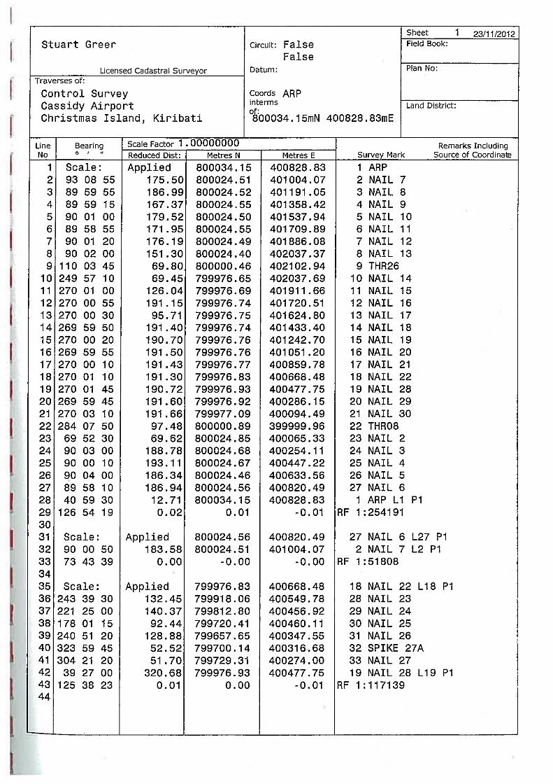
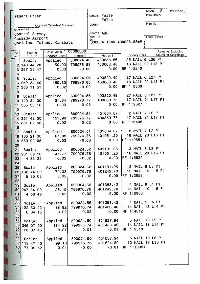
1. THE COORDINATES ARE IN TERMS OF A FALSE DATUM.
THE ORIGIN OF COORDINATES IS ARP.
400828.832mE, 8000034.149mN.
2. HEIGHTS ARE IN TERMS OF A FALSE DATUM SUPPLIED BY
AECOM ON 16/01/2013.
THE ORIGIN OF HEIGHTS IS ARP. RL=2.860m


AECOM
Pacific Aviation Investment Program (PAIP)
Obstacle Limitation Surface (OLS) Survey and Type A Chart - Cassidy International
Airport (CXI) - Kiribati (D-V2-1)
5 March 2013
Appendix B
ICAO Type A chart and data tables


Cassidy International Airport - Type A Table
Runway 08
Obstacle ID Description Distance fromSOT (m)
Distance fromFan Origin (m) CL Offset (m) Offset
DirectionWGS84Latitude
WGS84Longitude
ElliposoidalHeight (m)
Obstacle RL(m)
1.2% TakeoffRL (m)
1.2% TakeoffIntrusion (m)
1.6% TakeoffRL (m)
1.6% TakeoffIntrusion (m)
2.0% TakeoffRL (m)
2.0% TakeoffIntrusion (m)
T005 Tree 2685.9 432.9 6.9 L 1°59'10.73" 157°20'06.76" 30.7 9.5 7.7 1.7 9.5 0.0 11.2 -1.7
T004 Tree 2679.9 426.9 -5.5 R 1°59'10.31" 157°20'06.97" 30.2 1.4 7.7 -6.3 9.4 -8.0 11.1 -9.7
T006 Tree 2644.1 391.2 28.6 L 1°59'11.47" 157°20'08.18" 30.5 9.3 7.2 2.0 8.8 0.5 10.4 -1.1
T001 Tree 2349.4 96.4 -91.3 R 1°59'07.52" 157°20'17.63" 27.8 6.5 3.7 2.8 4.1 2.4 4.5 2.0
T002 Tree 2280.4 27.4 -82.8 R 1°59'07.82" 157°20'19.95" 28.1 6.9 2.9 4.0 3.0 3.9 3.1 3.8
T003 Tree 2264.5 11.5 -71.8 R 1°59'08.18" 157°20'20.47" 28.1 6.9 2.7 4.2 2.7 4.2 2.8 4.1

Cassidy International Airport - Type A Table
Runway 26
Obstacle ID DescriptionDistancefrom SOT(m)
Distancefrom FanOrigin (m)
CL Offset (m) OffsetDirection
WGS84Latitude
WGS84Longitude
ElliposoidalHeight (m)
Obstacle RL(m)
1.2% TakeoffRL (m)
1.2% TakeoffIntrusion (m)
1.6% TakeoffRL (m)
1.6% TakeoffIntrusion (m)
2.0% TakeoffRL (m)
2.0% TakeoffIntrusion (m)
T506 Tree 3010.8 757.8 76.7 L 1°59'08.08" 157°22'03.11" 51.8 30.6 11.4 19.2 14.4 16.2 17.5 13.1
T518 Tree 2776.5 523.5 101.0 L 1°59'07.29" 157°21'55.53" 45.2 23.9 8.6 15.3 10.7 13.2 12.8 11.1
T508 Tree 2948.0 695.0 86.7 L 1°59'07.75" 157°22'01.08" 46.4 25.2 10.7 14.5 13.4 11.7 16.2 9.0
T523 Tree 2712.1 459.1 97.5 L 1°59'07.40" 157°21'53.44" 42.4 21.1 7.8 13.3 9.7 11.5 11.5 9.7
T017 Tree 2935.4 682.5 -83.3 R 1°59'13.30" 157°22'00.65" 45.0 23.8 10.5 13.3 13.2 10.5 16.0 7.8
T516 Tree 2836.1 583.1 99.6 L 1°59'07.33" 157°21'57.46" 43.4 22.2 9.3 12.9 11.6 10.6 14.0 8.2
T525 Tree 2675.6 422.7 104.6 L 1°59'07.17" 157°21'52.26" 41.4 20.1 7.4 12.7 9.1 11.1 10.8 9.4
T509 Tree 2859.0 606.0 64.4 L 1°59'08.48" 157°21'58.20" 43.3 22.0 9.6 12.5 12.0 10.0 14.4 7.6
T512 Tree 2866.4 613.4 82.7 L 1°59'07.88" 157°21'58.44" 42.5 21.2 9.7 11.6 12.1 9.1 14.6 6.7
T531 Tree 2663.3 410.4 127.5 L 1°59'06.42" 157°21'51.87" 40.0 18.7 7.2 11.5 8.9 9.8 10.5 8.2
T530 Tree 2657.5 404.6 132.6 L 1°59'06.26" 157°21'51.68" 39.8 18.6 7.2 11.4 8.8 9.8 10.4 8.2
T511 Tree 2870.2 617.2 73.3 L 1°59'08.19" 157°21'58.56" 42.2 21.0 9.7 11.2 12.2 8.8 14.7 6.3
T517 Tree 2793.7 540.7 89.7 L 1°59'07.66" 157°21'56.08" 41.2 19.9 8.8 11.1 11.0 9.0 13.1 6.8
T014 Tree 2619.1 366.1 -99.9 R 1°59'13.84" 157°21'48.10" 36.0 17.7 6.7 11.0 8.2 9.6 9.6 8.1
T524 Tree 2695.3 442.4 101.0 L 1°59'07.29" 157°21'52.90" 39.8 18.5 7.6 10.9 9.4 9.2 11.2 7.4
T528 Tree 2656.3 403.3 120.6 L 1°59'06.65" 157°21'51.64" 39.3 18.1 7.2 10.9 8.8 9.3 10.4 7.7
T016 Tree 2936.1 683.1 -80.5 R 1°59'13.19" 157°22'00.67" 42.4 21.1 10.5 10.6 13.2 7.9 16.0 5.1
T541 Tree 2412.8 159.9 108.3 L 1°59'07.05" 157°21'43.76" 36.0 14.8 4.2 10.5 4.9 9.9 5.5 9.3
T315 Tree 2632.0 379.1 -129.2 R 1°59'14.82" 157°21'50.82" 38.3 17.3 6.9 10.5 8.4 9.0 9.9 7.4
T519 Tree 2771.8 518.9 95.9 L 1°59'07.45" 157°21'55.38" 40.0 18.8 8.5 10.2 10.6 8.1 12.7 6.1
T515 Tree 2824.4 571.4 80.2 L 1°59'07.96" 157°21'57.08" 40.5 19.3 9.2 10.1 11.5 7.8 13.7 5.5
T526 Tree 2669.8 416.8 92.9 L 1°59'07.55" 157°21'52.07" 38.5 17.3 7.3 9.9 9.0 8.3 10.6 6.6
T007 Tree 2478.1 225.1 27.3 L 1°59'09.69" 157°21'45.84" 35.9 14.7 5.0 9.7 5.9 8.8 6.8 7.9
T008 Tree 2483.3 230.3 29.2 L 1°59'09.63" 157°21'46.01" 36.0 14.7 5.1 9.6 6.0 8.7 6.9 7.8
T510 Tree 2859.5 606.6 69.3 L 1°59'08.32" 157°21'58.21" 40.4 19.2 9.6 9.6 12.0 7.2 14.4 4.7
T537 Tree 2607.9 354.9 98.3 L 1°59'07.37" 157°21'50.07" 37.3 16.0 6.6 9.5 8.0 8.0 9.4 6.6
T503 Tree 3316.4 1063.4 81.8 L 1°59'07.92" 157°22'13.00" 45.7 24.4 15.1 9.4 19.3 5.1 23.6 0.9
T527 Tree 2668.0 415.1 87.0 L 1°59'07.74" 157°21'52.02" 37.8 16.6 7.3 9.3 9.0 7.6 10.6 6.0
T536 Tree 2602.8 349.9 101.7 L 1°59'07.26" 157°21'49.91" 36.7 15.5 6.5 9.0 7.9 7.6 9.3 6.2
T521 Tree 2721.9 468.9 84.3 L 1°59'07.83" 157°21'53.76" 38.1 16.9 7.9 9.0 9.8 7.1 11.7 5.2
T011 Tree 2632.5 379.5 -64.2 R 1°59'12.68" 157°21'50.85" 36.9 15.6 6.9 8.7 8.4 7.2 9.9 5.7
T529 Tree 2652.7 399.7 125.8 L 1°59'06.48" 157°21'51.52" 36.7 15.5 7.1 8.4 8.7 6.8 10.3 5.2
T535 Tree 2601.5 348.5 131.9 L 1°59'06.28" 157°21'49.87" 36.0 14.7 6.5 8.2 7.9 6.8 9.3 5.4
T522 Tree 2702.3 449.3 73.6 L 1°59'08.18" 157°21'53.13" 37.0 15.8 7.7 8.1 9.5 6.3 11.3 4.5
T012 Tree 2645.3 392.3 -77.3 R 1°59'13.10" 157°21'51.26" 36.2 14.9 7.0 7.9 8.6 6.3 10.2 4.8
T539 Tree 2557.4 304.4 127.1 L 1°59'06.44" 157°21'48.44" 35.0 13.8 6.0 7.8 7.2 6.6 8.4 5.4
T013 Tree 2638.3 385.4 -93.6 R 1°59'13.63" 157°21'51.03" 36.0 14.7 6.9 7.8 8.5 6.3 10.0 4.7
T513 Tree 2842.5 589.5 73.8 L 1°59'08.18" 157°21'57.66" 38.3 17.1 9.4 7.7 11.7 5.4 14.1 3.0
T514 Tree 2831.9 578.9 76.6 L 1°59'08.08" 157°21'57.32" 38.1 16.9 9.3 7.6 11.6 5.3 13.9 3.0
T504 Tree 3033.3 780.3 47.6 L 1°59'09.03" 157°22'03.84" 40.5 19.3 11.7 7.6 14.8 4.5 17.9 1.4
T520 Tree 2727.7 474.7 90.5 L 1°59'07.63" 157°21'53.95" 36.5 15.2 8.0 7.2 9.9 5.3 11.8 3.4
T505 Tree 3018.8 765.8 51.5 L 1°59'08.90" 157°22'03.37" 39.9 18.7 11.5 7.2 14.6 4.1 17.6 1.1
T555 Tree 2923.2 670.2 -42.3 R 1°59'11.95" 157°22'00.27" 37.9 16.6 10.4 6.3 13.0 3.6 15.7 0.9
T009 Tree 2492.7 239.8 17.2 L 1°59'10.01" 157°21'46.31" 31.5 10.3 5.2 5.1 6.1 4.1 7.1 3.1
T553 Tree 2817.2 564.2 -96.8 R 1°59'13.73" 157°21'56.84" 35.1 13.9 9.1 4.8 11.3 2.5 13.6 0.3
T010 Tree 2548.0 295.0 -10.8 R 1°59'10.93" 157°21'48.10" 31.5 10.3 5.9 4.4 7.0 3.2 8.2 2.0
T545 Tree 2489.1 236.1 9.7 L 1°59'10.26" 157°21'46.23" 29.7 8.5 5.1 3.3 6.1 2.4 7.0 1.5
T546 Tree 2491.1 238.2 -10.6 R 1°59'10.92" 157°21'46.29" 29.6 8.4 5.2 3.2 6.1 2.3 7.1 1.3
T554 Tree 2837.9 584.9 -64.4 R 1°59'12.67" 157°21'57.51" 33.3 12.1 9.3 2.8 11.7 0.4 14.0 -1.9
T507 Tree 2981.1 728.2 58.3 L 1°59'08.68" 157°22'02.15" 33.7 12.5 11.0 1.4 14.0 -1.5 16.9 -4.4
R002 Building 2893.2 640.2 73.6 L 1°59'08.18" 157°21'59.30" 28.7 7.5 10.0 -2.5 12.6 -5.1 15.1 -7.6
T565 TreeGroundApproach 2479.5 226.5 27.5 L 1°59'09.68" 157°21'45.92" 23.4 2.2 5.0 -2.9 5.9 -3.8 6.8 -4.7
T566 TreeGroundApproach 2491.5 238.5 21.6 L 1°59'09.87" 157°21'46.31" 23.3 2.1 5.2 -3.1 6.1 -4.0 7.1 -5.0
T567 TreeGroundApproach 2488.2 235.3 8.7 L 1°59'10.29" 157°21'46.20" 23.2 1.9 5.1 -3.2 6.1 -4.1 7.0 -5.1
T568 TreeGroundApproach 2490.1 237.1 -6.8 R 1°59'10.79" 157°21'46.26" 23.1 1.9 5.2 -3.3 6.1 -4.2 7.1 -5.2
MAST 2 Mast 2-1 15379.7 13126.8 -286.7 R 1°59'19.97" 157°28'43.30" 66.9 45.7 159.8 -114.2 212.4 -166.7 264.9 -219.2

AECOM
Pacific Aviation Investment Program (PAIP)
Obstacle Limitation Surface (OLS) Survey and Type A Chart - Cassidy International
Airport (CXI) - Kiribati (D-V2-1)
5 March 2013
Appendix C
Approach OLS chart and data tables


Cassidy International Airport - Approach Obstacles
Runway 08/26
ObstacleID Description Chainage From 03
Threshold
Distance fromapproach fanorigin
Location in OLS Offset fromCentre Line Offset Direction WGS84 Latitude WGS84 Longitude Elliposoidal
Height (m)Obstacle RL(m)
Intrusion intoOLS
M001 Mast -718.0 1224.5 Approach Slope 26 -245.9 R of Approach 08 1°59'02.57" 157°21'56.97" 58.9 37.6 22.1T557 TreeGroundStripSouth -29.6 Transitional -123.0 R of Approach 08 1°59'06.57" 157°21'34.69" 40.1 18.8 16.4T548 Tree -124.3 630.8 Approach Slope 26 124.3 L of Approach 08 1°59'14.62" 157°21'37.75" 39.7 18.4 14.8T547 Tree -153.3 659.9 Approach Slope 26 101.3 L of Approach 08 1°59'13.87" 157°21'38.69" 39.1 17.9 13.7T569 TreeGroundApproach -152.4 658.9 Approach Slope 26 101.5 L of Approach 08 1°59'13.88" 157°21'38.66" 38.5 17.3 13.1T542 Tree -330.2 836.8 Approach Slope 26 -186.8 R of Approach 08 1°59'04.49" 157°21'44.42" 41.7 20.4 12.6T549 Tree -198.7 705.2 Approach Slope 26 118.7 L of Approach 08 1°59'14.44" 157°21'40.16" 38.2 17.0 11.8T506 Tree -907.8 1414.3 Approach Slope 26 -76.7 R of Approach 08 1°59'08.08" 157°22'03.11" 51.8 30.6 11.3T543 Tree -214.6 721.1 Approach Slope 26 -140.6 R of Approach 08 1°59'06.00" 157°21'40.68" 37.1 15.9 10.4T518 Tree -673.5 1180.0 Approach Slope 26 -101.0 R of Approach 08 1°59'07.29" 157°21'55.53" 45.2 23.9 9.3T532 Tree -531.4 1038.0 Approach Slope 26 -166.3 R of Approach 08 1°59'05.16" 157°21'50.93" 41.5 20.2 8.4T523 Tree -609.1 1115.6 Approach Slope 26 -97.5 R of Approach 08 1°59'07.40" 157°21'53.44" 42.4 21.1 7.8T540 Tree -458.9 965.4 Approach Slope 26 -150.6 R of Approach 08 1°59'05.67" 157°21'48.58" 39.2 18.0 7.6T525 Tree -572.7 1079.2 Approach Slope 26 -104.6 R of Approach 08 1°59'07.17" 157°21'52.26" 41.4 20.1 7.5T541 Tree -309.9 816.4 Approach Slope 26 -108.3 R of Approach 08 1°59'07.05" 157°21'43.76" 36.0 14.8 7.4T508 Tree -845.0 1351.5 Approach Slope 26 -86.7 R of Approach 08 1°59'07.75" 157°22'01.08" 46.4 25.2 7.1T533 Tree -533.4 1040.0 Approach Slope 26 -144.0 R of Approach 08 1°59'05.89" 157°21'51.00" 40.2 18.9 7.1T516 Tree -733.1 1239.6 Approach Slope 26 -99.6 R of Approach 08 1°59'07.33" 157°21'57.46" 43.4 22.2 6.4T530 Tree -554.6 1061.1 Approach Slope 26 -132.6 R of Approach 08 1°59'06.26" 157°21'51.68" 39.8 18.6 6.3T531 Tree -560.4 1066.9 Approach Slope 26 -127.5 R of Approach 08 1°59'06.42" 157°21'51.87" 40.0 18.7 6.3T014 Tree -516.1 1022.7 Approach Slope 26 99.9 L of Approach 08 1°59'13.84" 157°21'48.10" 36.0 17.7 6.2T007 Tree -375.1 881.6 Approach Slope 26 -27.3 R of Approach 08 1°59'09.69" 157°21'45.84" 35.9 14.7 6.0T017 Tree -832.5 1339.0 Approach Slope 26 83.3 L of Approach 08 1°59'13.30" 157°22'00.65" 45.0 23.8 5.9T008 Tree -380.3 886.9 Approach Slope 26 -29.2 R of Approach 08 1°59'09.63" 157°21'46.01" 36.0 14.7 5.9T528 Tree -553.3 1059.8 Approach Slope 26 -120.6 R of Approach 08 1°59'06.65" 157°21'51.64" 39.3 18.1 5.8T509 Tree -756.0 1262.5 Approach Slope 26 -64.4 R of Approach 08 1°59'08.48" 157°21'58.20" 43.3 22.0 5.8T315 Tree -529.1 1035.6 Approach Slope 26 129.2 L of Approach 08 1°59'14.82" 157°21'50.82" 38.3 17.3 5.6T538 Tree -449.3 955.8 Approach Slope 26 -130.5 R of Approach 08 1°59'06.33" 157°21'48.27" 36.9 15.7 5.5T524 Tree -592.4 1098.9 Approach Slope 26 -101.0 R of Approach 08 1°59'07.29" 157°21'52.90" 39.8 18.5 5.5T517 Tree -690.7 1197.2 Approach Slope 26 -89.7 R of Approach 08 1°59'07.66" 157°21'56.08" 41.2 19.9 4.9T534 Tree -501.3 1007.8 Approach Slope 26 -137.6 R of Approach 08 1°59'06.10" 157°21'49.95" 37.3 16.1 4.9T512 Tree -763.4 1269.9 Approach Slope 26 -82.7 R of Approach 08 1°59'07.88" 157°21'58.44" 42.5 21.2 4.8T537 Tree -504.9 1011.4 Approach Slope 26 -98.3 R of Approach 08 1°59'07.37" 157°21'50.07" 37.3 16.0 4.8T526 Tree -566.8 1073.3 Approach Slope 26 -92.9 R of Approach 08 1°59'07.55" 157°21'52.07" 38.5 17.3 4.8T511 Tree -767.2 1273.7 Approach Slope 26 -73.3 R of Approach 08 1°59'08.19" 157°21'58.56" 42.2 21.0 4.5T536 Tree -499.9 1006.4 Approach Slope 26 -101.7 R of Approach 08 1°59'07.26" 157°21'49.91" 36.7 15.5 4.3T519 Tree -668.9 1175.4 Approach Slope 26 -95.9 R of Approach 08 1°59'07.45" 157°21'55.38" 40.0 18.8 4.2T550 Tree -515.5 1022.1 Approach Slope 26 189.9 L of Approach 08 1°59'16.76" 157°21'50.41" 36.9 15.6 4.1T527 Tree -565.1 1071.6 Approach Slope 26 -87.0 R of Approach 08 1°59'07.74" 157°21'52.02" 37.8 16.6 4.1T011 Tree -529.5 1036.0 Approach Slope 26 64.2 L of Approach 08 1°59'12.68" 157°21'50.85" 36.9 15.6 3.9T515 Tree -721.4 1227.9 Approach Slope 26 -80.2 R of Approach 08 1°59'07.96" 157°21'57.08" 40.5 19.3 3.7T535 Tree -498.5 1005.0 Approach Slope 26 -131.9 R of Approach 08 1°59'06.28" 157°21'49.87" 36.0 14.7 3.6T539 Tree -454.4 960.9 Approach Slope 26 -127.1 R of Approach 08 1°59'06.44" 157°21'48.44" 35.0 13.8 3.5R001 Building 573.4 Transitional -193.7 R of Approach 08 1°59'04.26" 157°21'15.18" 33.3 12.1 3.5T521 Tree -618.9 1125.4 Approach Slope 26 -84.3 R of Approach 08 1°59'07.83" 157°21'53.76" 38.1 16.9 3.3T529 Tree -549.7 1056.2 Approach Slope 26 -125.8 R of Approach 08 1°59'06.48" 157°21'51.52" 36.7 15.5 3.3T016 Tree -833.1 1339.6 Approach Slope 26 80.5 L of Approach 08 1°59'13.19" 157°22'00.67" 42.4 21.1 3.3T012 Tree -542.3 1048.8 Approach Slope 26 77.3 L of Approach 08 1°59'13.10" 157°21'51.26" 36.2 14.9 2.9T510 Tree -756.6 1263.1 Approach Slope 26 -69.3 R of Approach 08 1°59'08.32" 157°21'58.21" 40.4 19.2 2.9T013 Tree -535.4 1041.9 Approach Slope 26 93.6 L of Approach 08 1°59'13.63" 157°21'51.03" 36.0 14.7 2.9T522 Tree -599.3 1105.8 Approach Slope 26 -73.6 R of Approach 08 1°59'08.18" 157°21'53.13" 37.0 15.8 2.6T003 Tree 2264.5 161.5 Approach Slope 8 -71.8 R of Approach 08 1°59'08.18" 157°20'20.47" 28.1 6.9 2.3T002 Tree 2280.4 177.4 Approach Slope 8 -82.8 R of Approach 08 1°59'07.82" 157°20'19.95" 28.1 6.9 2.0T520 Tree -624.7 1131.3 Approach Slope 26 -90.5 R of Approach 08 1°59'07.63" 157°21'53.95" 36.5 15.2 1.6T009 Tree -389.8 896.3 Approach Slope 26 -17.2 R of Approach 08 1°59'10.01" 157°21'46.31" 31.5 10.3 1.3T514 Tree -728.9 1235.4 Approach Slope 26 -76.6 R of Approach 08 1°59'08.08" 157°21'57.32" 38.1 16.9 1.1T513 Tree -739.5 1246.0 Approach Slope 26 -73.8 R of Approach 08 1°59'08.18" 157°21'57.66" 38.3 17.1 1.1T556 TreeGroundStripSouth -21.6 Transitional -123.2 R of Approach 08 1°59'06.56" 157°21'34.43" 24.5 3.2 0.9T552 Tree -676.9 1183.4 Approach Slope 26 182.8 L of Approach 08 1°59'16.53" 157°21'55.64" 36.5 15.2 0.5T602 TreeGroundStripNorth 490.9 Transitional 149.2 L of Approach 08 1°59'15.43" 157°21'17.85" 24.1 2.9 0.5T576 TreeGroundApproach -119.4 626.0 Approach Slope 26 154.0 L of Approach 08 1°59'15.59" 157°21'37.60" 25.2 4.0 0.4T596 TreeGroundTransitional 576.5 Transitional 151.8 L of Approach 08 1°59'15.51" 157°21'15.08" 24.2 3.0 0.4T559 TreeGroundStripSouth -35.9 Transitional -102.6 R of Approach 08 1°59'07.23" 157°21'34.90" 24.0 2.7 0.4T558 TreeGroundStripSouth -28.1 Transitional -102.2 R of Approach 08 1°59'07.24" 157°21'34.64" 24.0 2.7 0.4T001 Tree 2349.4 246.4 Approach Slope 8 -91.3 R of Approach 08 1°59'07.52" 157°20'17.63" 27.8 6.5 0.2T010 Tree -445.0 951.5 Approach Slope 26 10.8 L of Approach 08 1°59'10.93" 157°21'48.10" 31.5 10.3 0.2T577 TreeGroundTransitional -115.2 621.7 Approach Slope 26 161.6 L of Approach 08 1°59'15.83" 157°21'37.46" 25.2 4.0 0.1T562 TreeGroundStripSouth -55.8 Transitional -111.8 R of Approach 08 1°59'06.93" 157°21'35.54" 23.6 2.4 0.0T561 TreeGroundStripSouth -48.1 Transitional -111.4 R of Approach 08 1°59'06.95" 157°21'35.29" 23.6 2.3 0.0T560 TreeGroundStripSouth -39.6 Transitional -110.0 R of Approach 08 1°59'06.99" 157°21'35.01" 23.6 2.3 0.0T594 TreeGroundTransitional 344.8 Transitional 155.8 L of Approach 08 1°59'15.64" 157°21'22.57" 24.3 3.1 -0.1T563 TreeGroundApproach -75.5 582.0 Approach Slope 26 -120.7 R of Approach 08 1°59'06.64" 157°21'36.18" 23.7 2.5 -0.2T564 TreeGroundApproach -72.4 578.9 Approach Slope 26 -113.6 R of Approach 08 1°59'06.87" 157°21'36.08" 23.5 2.2 -0.4T545 Tree -386.1 892.6 Approach Slope 26 -9.7 R of Approach 08 1°59'10.26" 157°21'46.23" 29.7 8.5 -0.4T504 Tree -930.3 1436.8 Approach Slope 26 -47.6 R of Approach 08 1°59'09.03" 157°22'03.84" 40.5 19.3 -0.5T597 TreeGroundTransitional 633.6 Transitional 151.4 L of Approach 08 1°59'15.50" 157°21'13.23" 23.3 2.0 -0.5T546 Tree -388.2 894.7 Approach Slope 26 10.6 L of Approach 08 1°59'10.92" 157°21'46.29" 29.6 8.4 -0.5T593 TreeGroundTransitional 315.3 Transitional 160.8 L of Approach 08 1°59'15.81" 157°21'23.53" 24.4 3.2 -0.7T505 Tree -915.8 1422.3 Approach Slope 26 -51.5 R of Approach 08 1°59'08.90" 157°22'03.37" 39.9 18.7 -0.8T575 TreeGroundApproach -111.3 617.8 Approach Slope 26 155.0 L of Approach 08 1°59'15.62" 157°21'37.33" 23.8 2.6 -0.8T555 Tree -820.2 1326.8 Approach Slope 26 42.3 L of Approach 08 1°59'11.95" 157°22'00.27" 37.9 16.6 -1.0T574 TreeGroundApproach -118.2 624.7 Approach Slope 26 139.8 L of Approach 08 1°59'15.12" 157°21'37.56" 23.8 2.6 -1.0T503 Tree -1213.4 1719.9 Approach Slope 26 -81.8 R of Approach 08 1°59'07.92" 157°22'13.00" 45.7 24.4 -1.0T598 TreeGroundTransitional 735.6 Transitional 156.7 L of Approach 08 1°59'15.67" 157°21'09.93" 23.5 2.3 -1.0T595 TreeGroundTransitional 559.4 Transitional 162.8 L of Approach 08 1°59'15.87" 157°21'15.63" 24.3 3.0 -1.1T601 TreeGroundTransitional 757.6 Transitional 159.3 L of Approach 08 1°59'15.75" 157°21'09.22" 23.6 2.4 -1.3T573 TreeGroundApproach -141.3 647.8 Approach Slope 26 123.8 L of Approach 08 1°59'14.60" 157°21'38.31" 23.9 2.7 -1.3T592 TreeGroundTransitional 298.0 Transitional 159.2 L of Approach 08 1°59'15.75" 157°21'24.09" 23.5 2.3 -1.4T599 TreeGroundTransitional 746.0 Transitional 163.9 L of Approach 08 1°59'15.90" 157°21'09.59" 24.1 2.8 -1.5T553 Tree -714.2 1220.7 Approach Slope 26 96.8 L of Approach 08 1°59'13.73" 157°21'56.84" 35.1 13.9 -1.6T570 TreeGroundApproach -151.3 657.8 Approach Slope 26 102.0 L of Approach 08 1°59'13.89" 157°21'38.63" 23.8 2.6 -1.6T572 TreeGroundApproach -155.9 662.4 Approach Slope 26 108.6 L of Approach 08 1°59'14.11" 157°21'38.78" 23.9 2.6 -1.6T571 TreeGroundApproach -147.4 653.9 Approach Slope 26 109.8 L of Approach 08 1°59'14.15" 157°21'38.50" 23.5 2.3 -1.8T600 TreeGroundTransitional 755.5 Transitional 172.1 L of Approach 08 1°59'16.17" 157°21'09.28" 24.1 2.9 -2.6T578 TreeGroundTransitional -74.9 581.4 Approach Slope 26 179.5 L of Approach 08 1°59'16.42" 157°21'36.16" 25.1 3.9 -2.7T006 Tree 2644.1 541.2 Approach Slope 8 28.6 L of Approach 08 1°59'11.47" 157°20'08.18" 30.5 9.3 -2.9T005 Tree 2685.9 582.9 Approach Slope 8 6.9 L of Approach 08 1°59'10.73" 157°20'06.76" 30.7 9.5 -3.5T554 Tree -734.9 1241.4 Approach Slope 26 64.4 L of Approach 08 1°59'12.67" 157°21'57.51" 33.3 12.1 -3.8T579 TreeGroundTransitional -71.8 578.3 Approach Slope 26 188.5 L of Approach 08 1°59'16.71" 157°21'36.05" 25.1 3.9 -4.0M003 MAST 475.0 Transitional -314.8 R of Approach 08 1°59'00.32" 157°21'18.36" 43.0 21.7 -4.1T591 TreeGroundTransitional 263.6 Transitional 184.0 L of Approach 08 1°59'16.56" 157°21'25.20" 24.2 3.0 -4.2M000 MAST 706.4 Transitional -413.1 R of Approach 08 1°58'57.12" 157°21'10.88" 56.9 35.6 -4.3T583 TreeGroundTransitional 67.8 Transitional 186.5 L of Approach 08 1°59'16.64" 157°21'31.54" 24.5 3.3 -4.3T581 TreeGroundTransitional 5.9 Transitional 188.3 L of Approach 08 1°59'16.70" 157°21'33.54" 24.8 3.5 -4.4T584 TreeGroundTransitional 85.0 Transitional 188.1 L of Approach 08 1°59'16.70" 157°21'30.98" 24.4 3.2 -4.6T582 TreeGroundTransitional 30.4 Transitional 190.5 L of Approach 08 1°59'16.77" 157°21'32.75" 24.7 3.4 -4.7T585 TreeGroundTransitional 95.5 Transitional 196.3 L of Approach 08 1°59'16.96" 157°21'30.64" 24.0 2.8 -6.2T507 Tree -878.2 1384.7 Approach Slope 26 -58.3 R of Approach 08 1°59'08.68" 157°22'02.15" 33.7 12.5 -6.3T580 TreeGroundTransitional -57.4 Transitional 203.8 L of Approach 08 1°59'17.21" 157°21'35.59" 25.1 3.8 -6.3T565 TreeGroundApproach -376.5 883.0 Approach Slope 26 -27.5 R of Approach 08 1°59'09.68" 157°21'45.92" 23.4 2.2 -6.5T590 TreeGroundTransitional 233.0 Transitional 202.2 L of Approach 08 1°59'17.15" 157°21'26.19" 24.4 3.2 -6.6T566 TreeGroundApproach -388.5 895.0 Approach Slope 26 -21.6 R of Approach 08 1°59'09.87" 157°21'46.31" 23.3 2.1 -6.9T567 TreeGroundApproach -385.3 891.8 Approach Slope 26 -8.7 R of Approach 08 1°59'10.29" 157°21'46.20" 23.2 1.9 -6.9T588 TreeGroundTransitional 132.0 Transitional 207.2 L of Approach 08 1°59'17.32" 157°21'29.46" 24.8 3.6 -6.9T568 TreeGroundApproach -387.1 893.6 Approach Slope 26 6.8 L of Approach 08 1°59'10.79" 157°21'46.26" 23.1 1.9 -7.0T587 TreeGroundTransitional 110.5 Transitional 212.3 L of Approach 08 1°59'17.48" 157°21'30.16" 24.9 3.7 -7.6M004 MAST 551.2 Transitional -329.7 R of Approach 08 1°58'59.84" 157°21'15.90" 41.5 20.2 -7.8T589 TreeGroundTransitional 135.1 Transitional 214.6 L of Approach 08 1°59'17.56" 157°21'29.36" 24.8 3.6 -8.0T586 TreeGroundTransitional 94.1 Transitional 210.4 L of Approach 08 1°59'17.42" 157°21'30.69" 23.8 2.6 -8.4M002 MAST 508.6 Transitional -315.5 L of Approach 08 1°59'00.30" 157°21'17.28" 38.5 17.3 -8.7R002 Building -790.2 1296.7 Approach Slope 26 -73.6 R of Approach 08 1°59'08.18" 157°21'59.30" 28.7 7.5 -9.5T551 Tree -404.9 911.4 Approach Slope 26 312.8 L of Approach 08 1°59'20.76" 157°21'46.83" 36.9 15.6 -9.7T004 Tree 2679.9 576.9 Approach Slope 8 -5.5 R of Approach 08 1°59'10.31" 157°20'06.97" 30.2 1.4 -11.5