Embed Size (px)
Citation preview
,-
~OAJF~&9( t6 - - I INFRARED TRANSIENT-LIQUID-PHASE JOINING OF
SCS-6/p21S TITANIUM MATRIX COMPOSITE
Craig A. Blue and Vinod K. Sikka Oak Ridge National Laboratory*
Materials Processing Group Oak Ridge, Tennessee 3783 1-6083
and
Randall A. Blue and Ray Y. Lin Department of Materials Science and Engineering
M.L. #12 University of Cincinnati Cincinnati, Ohio 45221 -001 2
ABSTRACT
Fiber-reinforced titanium matrix composites (TMCs) are among the advanced materials being considered for use in the aerospace industry due to their light weight, high strength, and high modulus. A rapid infrared joining process has been developed for the joining of composites and advanced materials. Rapid infrared joining has been shown not to have many of the problems associated with conventioml joining methods. Two models were utilized to predict the joint evolution and fiber reaction zone growth. TMC, 16-ply SCS-6/p21S, has been successfully joined with total processing times of under 2 min utilizing the fipid infrared joining'technique. The process utilizes a So"C/sec ramping rate, 1 7 - p Ti-lSCu-lSNi wt 96 filler material between the faying surfaces; a joining temperature of 1 10°C; and 120 sec of time to join the composite material. Joint shear strength testing of the rapid infrared joints at temperatures as high as 800°C has revealed no joint failures. Also, due to the rapid cooling of the process, no poststabilization of the matrix material is necessary to prevent the formation of a brittle omega phase during subsequent use of the TMC at intermediate temperatures, 270 to 43OOC, for up to 20 h.
*Managed by Lockheed Martin Energy Systems under contract DE-AC05-84OR21400 with the U.S. Department of Energy.
-- -
t

2 .
1. INTRODUCTION
The requirement of structural materials for future aerospace vehicles and advanced applications necessitates the development of new materials with specific properties at elevated temperatures [l]. In order to use titanium matrix composites (TMCs) as structural components with complicated geometries, the successful development of joining techniques that provide strong bonds and do not weaken the base materials being joined is essential [2]. Cdnventional weldingljoining techniques typically proceed under critical conditions in which the reinforcing material is exposed to a superheated molten matrix for substantially long times [3]. This may give rise to accelerated reaction rates . be tween the matrix and reinforcing material, leading to extensive interdiffusion, reinforcement material dissolution, and possible total deterioration. In general, there are limited published works in the area of TMC joining and metal matrix composite (MMC) joining [4-71. Essentially no mature joining techniques have been established, especially for continuous fiber-reinforced composites [8 1. Diffusion bonding [8,9], laser beam welding [lo], and brazing [ll] are the techniques that have been investigated, thus far, for joining of continuous fiber- reinforced TMC. Electron beam welding has been utilized in the area of aluminum matrix composite joining in addition to the abovementioned methods [12]. Conventional fusion welding methods, such as arc or resistance welding, are likely to be only of limited use for joining composites since melting in these processes causes extensive reaction at the joint. Weld pool chemistry alterations, unacceptable distribution of, and interfacial reactions between, the reinforcement and matrix are typical problems encountered in -these techniques. -

3 limit the
reaction between the matrix and'reinforcement during joining. This may be accomplished by minimizing the size of the liquid pool during liquid state processes and minimizing the processing time in the cases of solid and liquid- solid state processing. In an effort to minimize the processing time in transient- liquid-phase (TLP) joining of TMC, a rapid infrared joining (RU) technique has b'een developed at the University of Cincinnati. The RIJ technique is a fast, simple, and economical process that does not require any vacuum. The process has been utilized to join many advanced materials that are inherently difficult to join [13,14].
A successful TMC joining method must be developed that will
In this study, a thin-film diffusion model was utilized for predicting the optimum joining temperature and time to form a joint free from any deleterious second phases. This reduced the experimental trial and error and gave a sound estimation of the joint evolution during isothermal or nonisothermal solidification. The kinetics of reaction zone growth between the SCS-6 fiber and the f321S matrix as a function of joining time and temperature were proposed based on this model. This allowed for the optimization of the joint while minimizing the fiber/matrix interfacial reaction. Furthermore, matrix phase stability a in terms of joining temperatures investigated and operation temperatures of the final TMC assembly were investigated. Results from this study allow for a fundamental understanding of the joint evolution during RIJ, the resultant fiber/matrix interfacial reaction growth, and phase stability qf the matrix. This provides for possible commercial implementation of the RIJ process.
2. THIN-FILM DIFFUSION MODEL
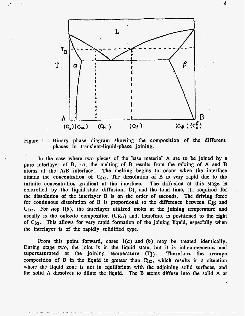
The TLP joining process can be analyzed in four stages by considering it as a moving boundary problem involving two phases, solid and liquid. We will use an arbitrary eutectic phase diagram between two elements, A and B, in Figure 1 for discussion. The four stages of the TLP joining process can be summarized as follows :
1.
2. 3. 4.
(a ) Dissolution of the interlayer B and formation of the joining alloy and (b) if using interlayer with a melting point lower than the joining temperature (Tj), melting of the interlayer. Homogenization of the liquid. Isothermal solidification. Homogenization of the joint region.
*B
T.
A B
4
Figure 1. Binary phase diagram showing the composition of the different phases in transient-liquid-phase joining.
In the case where two pieces of the base material A are to be joined by a pure interlayer of B, la, the melting of B results from the mixing of A and B atoms at the A/B interface. The melting begins to occur when the interface attains the concentration of Csa. The dissolution of B is very rapid due to the infinite concentration gradient at the interface. The diffusion at this stage is controlled by the liquid-state diffusion, D1, and the total time, tl , required for -
the dissolution of the interlayer B is on the order of seconds. The driving force for continuous dissolution of B is proportional to the difference between Clp and Cia. For step l(b), the interlayer utilized melts at the joining temperature and usually is the eutectic composition (mu) and, therefore, is positioned to the right of Cia. This allows for very rapid formation of the joining liquid, especially when the interlayer is of the rapidly solidified type.
From this point forward, cases l(a) and (b) may be treated identically. During stage two, the joint is in the liquid state, but it is inhomogeneous and supersaturated at the joining temperature (Tj). Therefore, the average cpmposition of B in the liquid is greater than Cla, which results in a situation where the liquid zone is not in equilibrium with the adjoining solid surfaces, and the solid A dissolves to dilute the liquid. The B atoms diffuse into the solid A at
5
the solid-liquid interface to form the primary solid solution, and the solid at the interface melts whenever the B concentration in the a-phase at the interface exceeds Csa.
During this dissolution of the base material, the diffusion in the.solid is c.ontrolled by the solid state diffusion (Ds), while the liquid phase undergoes homogenization, which is controlled by D1. The liquid zone will widen until it has a uniform concentration equal to that of Cla. The time for this process to occur will be designated as t2.
At the time the concentration of the liquid reaches Cla, the solid-liquid interface reverses direction. The liquid zone begins to shrink due to the enrichment of A in the liquid, due to the diffusion of B into A. The rate of loss of solute B from the liquid to solid 'A controls the rate of interfacial displacement towards the center of the joint. Therefore, the rate-controlling factor is the Ds of B into A . The time (tis) needed for this to occur is on the order of minutes to hours depending on Ds and temperature. After isothermal solidification, the joint may be held at a temperature of choice to homogenize the joint. Ds is the dominant. parameter, and the annealing time, tHom, can be much longer.
Due to the complex process of stage two and the extremely short period of time for it to occur, less than 1 sec, the modeling will begin with stage three. General solutions of the diffusion equation can be obtained for a variety of initial and boundary conditions provided that the diffusion coefficient is constant. The isothermal solidification of the joint defined as stage three has the following initial boundary conditions:
x c o x = o x > o
This is simply stating that the liquid composition in the joint follows the liquidus, and the solid follows the solidus.
The displacement of the interface results from the diffusion of the B component into the solid a-phase. This is a result of the concentration gradient, aCa/ax. The solute conservation requirement in the solid allows for the application of Fick's Law for the case of unidirectional diffusion when D is constant:
6
and the solution to this equation can be expressed as follows:
The total amount of substance diffusing in a cylinder of infinite length and unit cross section is given by:
and if the concentration distribution is that of expression (2.2), it is observed on writing:
x2/4D*t = €2 => dx = 2@t)0*5d€ , (2.4)
where E = x/2D*5-t*5 ,
that:
The expression (2.5) shows that the amount of the substance diffusing remains constant and equal to the amount originally deposited in plane x = 0. Substitution for A from Eq. (2.5) into (2.2) gives the following:
and this is the solution that describes the spreading of the initial amount of substance M (interlayer) placed at time t = 0 and in the plane x = 0. In Eq. (2.6), x is the distance in either direction perpendicular to the initial joining layer. The validity of Eq. (2.6) can be verified by two means. First, differentiation of Eq. (2.6) will show that it is a solution to Eq. (2.1). Second, Eq. (2.6) must satisfy the following boundary conditions:
C--> 0 as t--> - for 1 x 1 > O C-> - as t--> 0 for x = 0
Also, the temperature dependence for the time for isothermal solidification may be introduced through the Arrhenius relation:

7
where, Do has the value of 3.16 x 105 cm2/sec, QCU has the value of 331 kJ/mole, and R has the value of 8.314 J/"K-mole [15]. Utilizing the Arrhenius relation, Table 1 shows the calculated diffusion coefficient for Cu in Ti as a function of temperature.
Table 1. The calculated diffusion coefficient for Cu in Ti as a function of temperature
. Joining temperature Diffusion coefficient
950°C 1005°C 1050°C 1100°C 1150°C
2.3 x 10⁻⁹ cm2/sec 8.3 x 10⁻⁹ cm2/sec 2.7 x 10⁻⁸ cm2/sec 8.1 x 10⁻⁸ cm2/sec 2.2 x 10⁻⁷ cm2/sec
An attempt was made to simplify the multielement, 82 1 S/Ti- 15Cu- 15Ni, system to a two-element system, Ti-Cu, for the purpose of modeling. The elements (Mo, Nb, Cu, and Ni) are all beta stabilizers, AI is an alpha stabilizer, and Cu and Ni have similar atomic radii. Processing below 1003°C would not be feasible in the Ti-Cu system due to the fact that below this temperature, a two- phase region consisting of Ti2Cu and 8-Ti exists. The Ti2Cu phase would be detrimental to the joint shear strength. In terms of the limited phase equilibrium Ti-Cu-Ni ternary work by Shalin and Kovneristy [16], the solid eutectic phases in the system are 8-Ti, Ti2Cu (6), and Ti2Ni (E). The E and 6 phases first appear at temperatures below 1003"C, which further suggests that the Ti-Cu binary assumption is valid. From these calculations and observations, a processing temperature of 1005°C or greater and a processing time in accordance with Table 2 would allow for isothermal solidification of 8-Ti without any intermetallic phase such as E and 6.
Taking Eq. (2.6), setting x equal to zero, only being concerned with the center of the joint, and solving for time, it is possible to calculate the time for isothermal solidification at each of the possible joining temperatures. This will allow for the prediction of the joining time necessary to yield a joint of any composition chosen. Performing these operations will yield Eq. (2.8):

8
From experimental verification it was observed that the average joint width was 31.8 pm and the standard deviation was 0.7 pm when isothermal solidification began to proceed. From the binary Ti-Cu phase diagram, the isothermal solidification begins when a Cu concentration of 27 a/o Cu, the liquidus composition at the joining temperature, is homogeneous across the liquid zone. The solid solidifying out will have the composition of 11.4 a/o, the solidus composition at the joining temperature. Table 2 lists the calculated times (see Eq. 2.8) for solidification for various processing temperatures.
Time required for isothermal solidification Table 2. at varied processing temperatures.
Joining temperature tI s
1005°C 1050°C 1100°C 1150°C
550 sec 169 sec
56 sec 20 Sec
Utilizing Eq. (2.6) and setting x equal to zero to look only at the center of the joint, calculations can be made in order to verify the center of thejoint composition with further holding after isothermal solidification. A homogenized joint will be defined as having 5 wt % solute in the joint. This value was chosen because this concentration of solute would intersect the solidus at approximately 1485"C, which should provide a joint that is able to withstand high-temperature (600 to 815°C) environments. Similar 5 wt % assumptions have been made by other workers in the area of Ti-based joining 1151. Calculations of the total joining time necessary to achieve the 5 wt % solute in the joint area, tHom, for the possible processing temperatures are shown in Table 3.
Table 3. The calculated joining times necessary to homogenize a joint at varied processing temperatures.
Joining temperature tHom
1005°C 1050°C 1100°C 1150°C
1348 sec 412 sec 137 sec 49 sec

9
3. FIBER REACTION ZONE GROWTH MODEL
Now that the potential joining times and temperature that result in a homogeneous joint, defined as having 5 wt 96 solute or less, have been identified, the resultant effects on the fiber reinforcement may be evaluated. The growth of reaction layers between the Sic reinforcement and the Ti matrix has been studied by Martineau et al. 1171. The potential for a reaction to occur is determined by thermodynamic factors, but the extent of the reaction is controlled by kinetic parameters. Kinetics of reactions are controlled by processing variables such as time, temperature, and the diffusion/chemical reaction rates 'of the components in the composite. The thickness of a reaction layer, x, in an Sic-Ti composite system has been shown to increase linearly with the square root of the heating time, t, at a given temperature providing the reaction layer is not too thick [17]. The equation for the reaction layer thickness may be written as:
where k is the parabolic rate constant of the reaction following an Arrhenius temperature dependence. Therefore, Eq. 3.1 becomes:
where R is the gas constant, ko is the pre-exponential factor, T is the absolute temperature, b is the original thickness, and Qr is the activation energy for the diffusion phenomena. In the temperature range of 700 to llOO°C, the measured values of Qr and ko were 232 kJ/mol and 0.122 cm/so=5, respectively, as reported by Gundel and Wawner [18] in the study of the j321S matrix with the SCS-6 reinforcement. These reaction constants were determined over a range of temperatures and were used to construct an Arrhenius plot in which a least- squares line was fitted through the data points to yield the values of Q and ko.
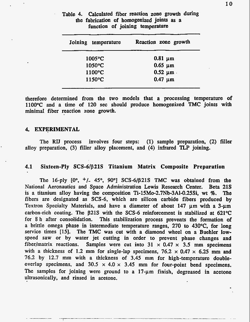
Therefore, using the kinetics growth model, Eq. (3.2), by Martineau et al. [17] and the Qr and ko values from Gundel and Wawner [18] for the j321S matrix with the SCS-6 reinforcement, predictions for reaction zone growth for the possible joining parameters can be obtained. Table 4 lists the calculated fiber reaction zone growth during the fabrication of homogenized joints having less than 5 wt % solute in the centers of the joints as a function of joining temperature.
As can be seen in Table 4, higher joining temperatures for shorter holding It was times result in a homogenized joint with less reaction zone growth.
10
Table 4. Calculated fiber reaction zone growth during the fabrication of homogenized joints as a
function of joining temperature
Joining temperature Reaction zone growth
1005°C 1050°C 1100°C 1150°C
0.81 pm 0.65 pm 0.52 pm . 0.47 pm
therefore determined from the two models that a processing temperature of 1100°C and a time of 120 sec should produce homogenized TMC joints with minimal fiber reaction zone growth.
4. EXPERIMENTAL
The RIJ process involves four steps: (1) sample preparation, (2) filler alloy preparation, (3) filler alloy placement, and (4) infrared TLP joining.
4.1 Sixteen-Ply SCS-6/p21S Titanium Matrix Composite Preparation
The 16-ply [O", +/- 45", 90°] SCS-6/p21S TMC was obtained from the National Aeronautics and Space Administration Lewis Research Center. Beta 21 S is a titanium alloy having the composition Ti-lSMo-2.7Nb-3Al-O,25Si, wt 96. The fibers are designated as SCS-6, which are silicon carbide fibers produced by Textron Specialty Materials, and have a diameter of about 147 pm With a 3-pm carbon-rich coating. The p21S with the SCS-6 reinforcement is stabilized at 621°C for 8 h after consolidation. This stabilization process prevents the formation of a brittle omega phase in intermediate temperature ranges, 270 to 43OoC, for long service times [15]. The TMC was cut with a diamond wheel on a Buehler low- speed saw or by water jet cutting in order to prevent phase changes and fiber/matrix reactions. Samples were cut into 31 x 0.47 x 3.5 mm specimens with a thickness of 1.2 mm for single-lap specimens, 76.2 x 0.47 x 6.25 mm and 76.2 by 12.7 mm with a thickness of 3.45 mm for high-temperature double- overlap specimens, and 30.5 x 4.0 x 3.45 mm for four-point bend specimens. The samples for joining were ground to a 17-pm finish, degreased in acetone ultrasonically, and rinsed in acetone.
11
4.2 Filler Alloy Preparation
The filler material used in this study was a 17-pm-thi~k foil of METGLAS Brazing Foil 5003 (MBF 5003) that Consisted of a composition of Ti-15Cu-15Ni wt %. This foil was produced by a rapid solidification (RS) process. The RS is characterized by cooling rates approaching 106"Clsec. Because RS microcrystalline and amorphous materials are compositionally much more uniform, their melting under transient heating occurs over a narrower temperature range. The RS foil has solidus and liquidus temperatures of 902 and 932OC, respectively, during transient heating. The RS foil allows for joining at lower temperatures for shorter times. This is particularly important when base material parts being joined lose their inherent strength due to annealing during joining. Also, the amount of solute content can ,be reduced while still maintaining a reasonable joint interlayer thickness, and the elemental compatibility with the base materials being joined. Also, limited characterization of the available titanium- based RS foils revealed that the MBF 5003 was the preferred filler material [ll]. After selection of the type of filler, the MBF 5003 filler material was cut to the appropriate size, degreased in acetone ultrasonically, and iinsed in acetone.
The MBF 5003 was chosen due to these reasons.
4.3 Joining
The TMC specimens with the filler metal were then placed in an infrared furnace in the appropriate joint configuration according to the type of postmechanical testing desired. Parts were kept in place by a carbon screw, tightened by hand before loading the assembly into the furnace. No pressure was maintained during bonding because of the absence of autonomic load compensation for the expansion of the specimens and liquidification of the joining material. The processing temperature was monitored with a chromel- alumel (K-type) thermocouple spot welded on the specimen near the joint area. The specimens were argon purged for approximately 60 sec prior to the heating cycle. During the entire joining process, argon was purged through the heating chamber at 250 mL/min in order to prevent oxidation. Typically, the temperature of the specimen was brought to a preset joining temperature in 20 to 30 sec and then held at that temperature for various lengths of time before the power was terminated. The joining temperature was 1100"C, and the joining time was varied from 5 to 300 sec. The variation of time at temperature was accomplished in order to study the effects of joining time on the fiber/matrix reaction zone growth, joint evolution, phase stability of the matrix, and the effects of these on the joint and base material mechanical properties. Four-point bend samples were infrared thermally cycled at these parameters to verify changes in TMC properties. After joining, the sample cooled naturally in an argon atmosphere. The cooling rate was-rapid due to the
1 2
cold wall process of infrared heating, in which, due to selective transmitting power and emissivity, only the Sample was heated to the desired temperature. The samples normally cooled to below 900°C in less than 1Osec and reached ambient temperature in approximately 5 min.
5. RESULTS AND DISCUSSION
Two models were utilized in this study to outline the optimum joining time and temperature that minimize the trial-and-error experiments. A . thin-film diffusion model in conjunction with the Ti-Cu binary phase diagram was used to predict the time for isothermal solidification of the joint and homogenization of the joint. Utilizing the thin-film diffusion model and the binary Ti-Cu phase diagram, isothermal solidification of B-Ti without any intermetallic phase, such as Ti2Cu (6) and Ti2Ni (E), could be obtained in 20 sec at 115OoC, 56 sec at llOO°C, 169 sec at 1O5O0C, and 550 sec at 1005°C. These joining times and temperatures should result in joints with solute concentrations of 14 wt %. Again, utilizing the thin-film diffusion equation and the Ti-Cu binary phase diagram, it was calculated that times of 1348, 412, 137, and 49 seconds for processing temperatures of 1005, 1050, 1100, and 1 150°C, respectively, would be necessary to obtain a solute concentration of 5 wt % in the center of the joint (homogenization).
I
The reaction zone growth kinetics were modeled with a parabolic growth law. Using the times necessiry for homogenization of the joint at the four temperatures of interest, the resultant reaction zone growths were calculated. Reaction zone growths of 0.81, 0.65, 0.55, and 0.47 pm were calculated for temperatures of 1005, 1050, 1100, and 1 150°C, respectively. From these calculations, a temperature of 1100°C and a time of 120 sec were chosen as optimum joining conditions.
- Joining at 1100°C for 30 sec resulted in nonisothermal solidification as depicted by the thin-film diffusion model. Scanning electron microscope (SEM) observations and energy dispersive X-ray analysis (EDAX) results from the sample processed at 1100°C for 30 sec, Figure 2, showed that indeed the first solid to solidify had an average composition of 15.9 wt % solute, points 4 and 5, which is in good agreement with the Ti-Cu binary phase diagram. Also, as one traverses toward the center of the joint, the amount of solute increases as expected, and the remaining liquid frozen out in the joint, point 1, had a composition of approximately 37 wt % solute. This suggests that the liquid had followed the liquidus composition down to the peritectic temperature. As seen by the microstructures and EDAX results, the Ti-Cu binary phase diagram sufficiently predicts the behavior of the joint during nonisothermal solidification.
-.

13
Figure 2. Scanning electron microscope micrographs of infrared joined . titanium matrix composite joint for 30 sec processing time at
lloooc. According to the calculated time required for isothermal solidification,
a holding time of 60 sec at 1100°C would be sufficient for complete isothermal solidification across the joint area. Optical and SEM microstructural observations of the joint processed at 1100°C for 60 sec revealed an isothermal solidified microstructure as shown in Figure3. EDAX in the center of the joint, point 1, reveals that a composition of 15.2 wt % solute is present, which is similar to the 14 wt% predicted by the Ti-Cu phase diagram. Also, EDAX spot analysis over the entire joint area, points 1 through 5, shows an average solute content of 15.3 wt %, which shows good agreement with the Ti-Cu phase diagram and the calculated 56-sec isothermal solidification. Holding at the joining temperature of 1100°C beyond 60 sec will cause further diffusion and homogenization of the joint as shown in Figure4. The center of the joint, point 1, had an average solute composition of 5 wt % and decreased to 3 wt % at point 6. This will increase the melting point of the joint as the composition goes up the solidus.
The calculated compositions in the centers of the joints for samples joined at llOO°C, for 90, 120, and 300 sec are 8.3, 5.6, and 3.0 wt % solute, respectively. The compositions in the centers of the joints processed at llOO°C for 90, 120, and 300 sec are 6.2, 6.8, and 3.3 wt % solute, respectively, as measured by EDAX. These concentrations agree reasonably well with the values calculated with the thin-film diffusion equation.

14
Figure 3. Scanning electron microscope micrographs of infrared joined titanium matrix composite joint for 60-sec processing time at 11oooc.
- - Figure 4. Scanning electron microscope micrographs of infrared joined
titanium matrix composite joint for 90-sec processing time at l1Oo0C.

1 5
Reaction zone growth measurements were taken on SCS-6/p21 S titanium composites samples in the as-received, 1100°C thermal cycled for 30-, 120-, and 300-sec conditions. The increase in the reaction zone thickness was 0.19, 0.44, and 0.62 pm for the 30-, 120-, and 300-sec processed samples and had standard deviations of 0.14, 0.15, and 0.19 pm, respectively. The results from the fiber reaction zone growth model reveal an increase in the fiber reaction zone for the llOO°C cycle of 0.26, 0.52, and 0.81 pm for the 30-, 120-, and 300- sec processed samples, respectively. The calculated and measured values compare reasonably well.
Four-point bend testing of the as-received and infrared-cycled TMC was performed to reveal the effects of the processing technique on the mechanical properties of the TMC. The infrared processing technique causes a 14 to 18% drop in the initial elastic modulus and a 3.8% drop in the ultimate bend strength. It was shown that these decreases were due to the elimination of the a-phase in the material. Heat treating at 621°C for 8 h would completely recover the initial elastic modulus and ultimate bend strength.
Postheat treatments of the infrared-cycled TMC at temperatures of 280 and 4270C for up to 10 h were accomplished in order to reveal if the material had to be restabilized after processing to prevent o-phase embrittlement. The temperatures and times chosen here are according to the national aerospace plane predicted flight cycle. Four-point bend testing, microhardness testing, microstructural analysis, X-ray, and comparisons made with results of other p21 S studies suggest conclusively that o-phase embrittlement is not occurring.
Joint shear strengths for the optimized infrared TLP joining parameters of 1100°C for 120 sec were not attainable due to failure outside the joint area. Utilizing four-ply [O"] SCS-6/p21S and neat p21S, joint shear strengths of 642.5 and 610 MPa, respectively, were obtained. Failure did not occur through the joint area for either sample. It was therefore assumed that the joint shear strengths were on the order of 610 to 642.5 MPa, which would be similar to the interlaminar shear strength of the TMC.
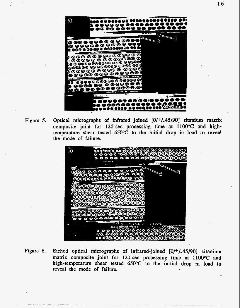
Double-overlap 16-ply TMC specimens, in an overlap configuration, were infrared joined utilizing optimum joining parameters extracted from this study of 1100°C for 120 sec and were tested in air at 650 and 815°C. Failure for both the 650 and 815°C test temperatures was in the base material at the first row of SCS-6 fibers as shown in Figures 5 and 6, points 2 and 4. Figure 6 is an etched sample that emphasizes the beta-enriched joint area, point 3. Therefore, as seen in all the joint shear strength testing, utilizing the infrared TLP joining parameters indicated by the thin-film diffusion model (1 100°C for 120 sec), joint failure will not occur even at testing temperatures as high as 815°C.
16
I
0
Figure 5. Optical micrographs of infrared joined [0/+/-45/90] titanium ma&x I composite joint for 120-sec processing time at 1100°C and high-
temperature shear tested 650°C to the initial drop in load to reveal the mode of failure.
Figure 6. Etched optical micrographs of infrared-joined [0/+/-45/90] titanium matrix composite joint for 120-sec processing time at 1100°C and high-temperature shear tested 650°C to the initial drop in load to reveal the mode of failure.
1 7
6. CONCLUSIONS
An RIJ process has been developed at the University of Cincinnati for the joining of advanced materials. Two models have been utilized to predict the joint evolution and fiber reaction zone growth for the TLP joining of SCS-6/j321 S cmposite with Ti-15Cu-15Ni filler. Calculated and experimental results miitsh well and suggest that higher joining times for shorter periods of time are most effective in producing homogenized joints while limiting fiber reaction zone growth. Joints produced utiliiing this process show no joint failures at temperatures as high as 815OC in air. Also, due to the rapid cooling of the infrared joining process, the poststabilization process necessary with conventional joining processes to prevent a-phase formation and optimize joint parameters is not necessary.
7. ACKNOWLEDGMENTS
The financial support from Oak Ridge National Laboratory, NASA Lewis Research Center, Ohio Edison Material Technology Center, and NASA Space Engineering Research Center at the University of Cincinnati is very much appreciated. The authors would also like to thank Paul Becher and Jim King for reviewing the manuscript, Mike Miller and Drago Adrojna of NASA LeRC for their technical assistance, Glenda Carter for manuscript preparation, and Kathy Spence for editing.
8.
1.
2.
3. 4. 5 . 6. 7.
8.
9.
REFERENCES I
Tenney, D. R., Lisagor, W. B., and Dixon, S. C., "Materials and Structures for Hypersonic Vehicles," NASA Technical Memorandum 101501, October 1988. Irving, B., "What's Being Done to Weld Metal-Matrix Composites," Weld. J.,
Devletian, J. H., Weld J., Vol. 6, p. 33, 1987. Ahearn, J. S., Cooke, C., and Fishman, S . G., Met. Constr., Vol. 14, p. 192, 1982. Iseki, T., Kameda, T., and Maruyama, T., J. Mater. Sci., Vol. 19, p. 1692, 1984. Kennedy, J. R., Weld. J., Vol. 52, pp. 12Os-l24s, 1973. Partrige, P. G., and Ward-Close, C. M., Met. Mater., Vol. 5(6), pp. 334-339, 1989. Goddard, D. M., Pepper, R. T., Upp, J. W., and Kendall, E. G., Weld. J., Vol. 51,
Hirose, A., Kotoh, M., Fukumoto, S., and Kobayashi, K. F., "Diffusion Bonding of SIC Fibre-Reinforced Ti-6A1-4V Alloy," Mater. Sci. Technol., Vol. 8,
Vol. 70, pp. 65-67, 1991.
pp. 1 7 8 ~ - 1 8 2 ~ , 1972.
pp. 811-815, 1992.

1 8 10. Hall, I. W., and Lirn, J.-L., "Microstructural Analysis of Isothermally Exposed
Ti/SiC Metal Matrix Composites," J. Mater. Sci., Vol. 27, pp. 3835-3842, 1992. 11. Hirose, A., Matshuhiro, Y., Kotoh, M., Fukumoto, S., and Kobayashi, K. F.,
"Laser-beam welding Sic Fibre-Reinforced Ti-6A1-4V Composite," J. Mater.
12. Hoffman, E., Bird, R., and Dicus, D., "Effect of Braze Processing on the Microstructure and Mechanical Properties of SCS-6/821 S Titanium Matrix Composites," American Institute of Aeronautics and Astronautics Fourth International Aerospace Planes Conference, pp. 1-1 0, 1992.
13. Blue, C. A,, Blue, R. A., and Lin, R. Y., "Microstructural Evolution Resulting from Reactibns Between TiAl and a Liquid Ti Alloy," Accepted for publication in Scr. MetaN., 1993.
14. Blue, C. A., Blue, R. A,, and Lin, R. Y., "Infrared Joining of TiAl," Accepted for publication in Proc. Adv. Mater., March 1994.
15. Wells, R. R., Weld J., Vol. 3(1), p. 205, 1976. 16. Shewmon, P. G., "Diffusion in Solids," McGraw-Hill Book Co., New York, 1963. 1 7. Martineau, P., et al., J. Mater. Sci., Vol. 19(8), p. 2749, 1984. 18. Gundel, D. B., and Wawner, F. E., Scri. Metall., Vol. 25, pp. 437-441, 1991.
S C ~ . , Vol. 28, pp. 349-355, 1993.
DISCLAIMER
This report was prepared as an account of work sponsored by an agency of the United States Government. Neither the United States Government nor any agency thereof, nor any of their employees, makes any warranty, express or implied, or assumes any legal liability or responsi- bility for the accuracy, completeness. or usefulness of any information, apparatus, product, or process disclosed, or represents that its use would not infringe privately owned rights. Refer- ence herein to any specific commercial product, process, or service by trade name, trademark, manufacturer, or otherwise does not necessarily constitute or imply its endorsement, recom- mendation, or favoring by the United States Government or any agency thereof. The views and opinions of authors expressed herein do not necessarily state or reflect those of the United States Government or any agency thereof.
~ -~ _ _ ~ ~ - ~~
~~


![T6 · 2020-02-17 · 1 SR.23 - 13 anuary 217 T6 7243 iller Drive arren 482 S Tel. 1 586-268-122 T6 EN FR T6-AF-1.45 T6-BF-4.62 T6-AU-1.45 T6-AU-3.24 Weight [lb] 2.2 4.23 2.16 4.09](https://img.dokumen.tips/doc/110x75/5f1643d893e9d01b883d4f0e/t6-2020-02-17-1-sr23-13-anuary-217-t6-7243-iller-drive-arren-482-s-tel-1-586-268-122.jpg)

![Wasif safeen1 2 1...Palanivel et al. [27] also reported that high tensile strength can beachieved by square tool pin profile while joining two dissimilar AA5083H111 and AA6351- T6](https://img.dokumen.tips/doc/110x75/60b8621796d9c07cdf4e0d32/wasif-safeen1-2-1-palanivel-et-al-27-also-reported-that-high-tensile-strength.jpg)


![T6 Locali nord-centro-sud [3780x594] Tavola T6 · Title U:\Rome\Projects \9\27\01\Outputs\Reports\110919_Consegna_Finale\Tavole DWG\T6 Locali nord-centro-sud [3780x594] Tavola T6](https://img.dokumen.tips/doc/110x75/605cc8f6174acb1ae71316a3/t6-locali-nord-centro-sud-3780x594-tavola-t6-title-uromeprojects-92701outputsreports110919consegnafinaletavole.jpg)