Embed Size (px)
Citation preview

NX for China GearModeling-8.5
1
NX GC 工具箱
(齿轮建模工具)
用户手册
Oct 2012
NX8.5
Siemens PLM Software

NX for China GearModeling-8.5
2
版本历史
手册版本 NX版本 发布日期
1.0 6.0.4.3 2009-05-31
2.0 7.5 2010-01-28
3.0
4.0
5.0
8.0
8.0.1
8.5
2011-10-10
2012-01-30
2012-07-02
版权申明 本软件和相关文档属于 Siemens Product Lifecycle Management Software Inc.所有。
©Siemens Product Lifecycle Management Software Inc. 版权所有。
所有注册商标均归属各自所有者。

NX for China GearModeling-8.5
3
Table of Contents
Gear Modeling Introduction ....................................................................................... 4
Example: Gear Modeling with Addendum Modification Coefficient ..................... 5
Example: Engaging Gears ......................................................................................... 10
Display Gear Type ...................................................................................................... 15
Cylinder Gear Modeling ............................................................................................ 16
Bevel Gear Modeling ................................................................................................. 20

NX for China GearModeling-8.5
4
Gear Modeling Introduction
The Gear Modeling lets you create parametric geometry models of cylinder gears, bevel
gears.
You can also edit gears and retain geometric relations with other entities, display gear
geometric information, and translate, engage, delete, and display gears.
Precise modeling is supported for:
Cylinder gears:
Involute straight cylindrical external gears
Involute straight cylindrical internal gears
Involute helical cylindrical external gears
Involute helical cylindrical internal gears
Bevel gears:
Straight bevel gears
Helical bevel gears

NX for China GearModeling-8.5
5
Example: Gear Modeling with Addendum Modification
Coefficient
This example lets you create two involute cylinder gears using the Addendum Modified Gear
method. You then use the Engage Gear and Gear Motion capabilities to relate and animate
the gears.
Modeled and Engaged Gears
Start Gear Modeling from the NX Application menu and select the type of gear you want to
create.
You can also pick the appropriate button on the Gear Modeling toolbar to create
gear.
Create Cylinder Gears
The following text describes the processes you can use to create involute cylinder gears with
addendum modification coefficients.
Create a Part
Begin by creating a part using File->New
For this example, select millimeter units.
Create a Driving Gear
The following text describes processes you use to create an involute cylinder driving gear.
1. Click Cylinder Gear Modeling on Gear Modeling toolbar, or select Cylinder Gear
Modeling from the menu, to display the Involute Cylinder Gear Modeling dialog.
NX for China GearModeling-8.5
6
2. On the Involute Cylinder Gear Modeling dialog, select Create Gear as the Gear
Operating Type, then pick OK to display the Involute Cylinder Gear Type dialog.
3. On the Involute Cylinder Gear Type dialog, select General Gear, Straight Gear,
External Gear, and Hobbing for Machining, then click OK to display the Involute
Cylinder Gear Parameter dialog.
4. Select the Addendum Modified Gear tab.
5. Click Default Values to add parameter values.
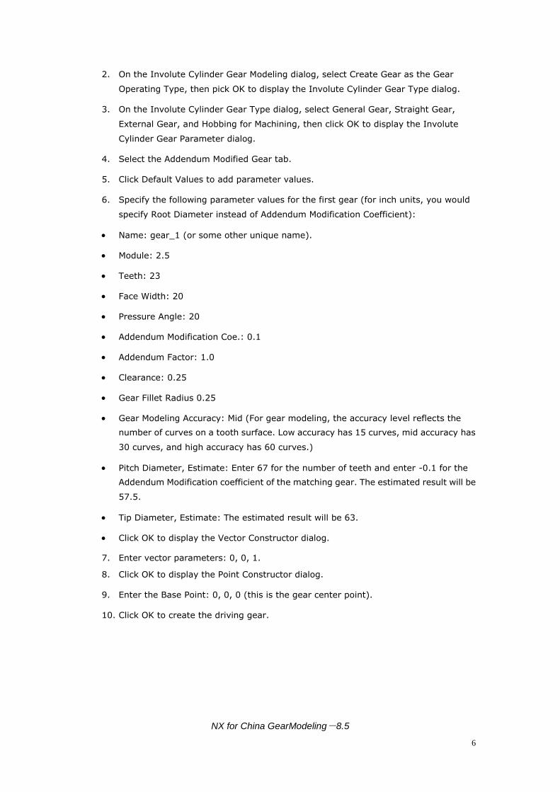
6. Specify the following parameter values for the first gear (for inch units, you would
specify Root Diameter instead of Addendum Modification Coefficient):
Name: gear_1 (or some other unique name).
Module: 2.5
Teeth: 23
Face Width: 20
Pressure Angle: 20
Addendum Modification Coe.: 0.1
Addendum Factor: 1.0
Clearance: 0.25
Gear Fillet Radius 0.25
Gear Modeling Accuracy: Mid (For gear modeling, the accuracy level reflects the
number of curves on a tooth surface. Low accuracy has 15 curves, mid accuracy has
30 curves, and high accuracy has 60 curves.)
Pitch Diameter, Estimate: Enter 67 for the number of teeth and enter -0.1 for the
Addendum Modification coefficient of the matching gear. The estimated result will be
57.5.
Tip Diameter, Estimate: The estimated result will be 63.
Click OK to display the Vector Constructor dialog.
7. Enter vector parameters: 0, 0, 1.
8. Click OK to display the Point Constructor dialog.
9. Enter the Base Point: 0, 0, 0 (this is the gear center point).
10. Click OK to create the driving gear.
NX for China GearModeling-8.5
7
Example Driving Gear
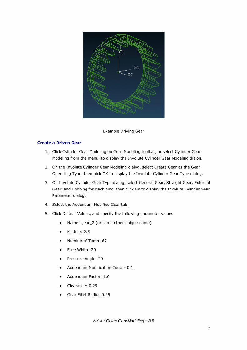
Create a Driven Gear
1. Click Cylinder Gear Modeling on Gear Modeling toolbar, or select Cylinder Gear
Modeling from the menu, to display the Involute Cylinder Gear Modeling dialog.
2. On the Involute Cylinder Gear Modeling dialog, select Create Gear as the Gear
Operating Type, then pick OK to display the Involute Cylinder Gear Type dialog.
3. On Involute Cylinder Gear Type dialog, select General Gear, Straight Gear, External
Gear, and Hobbing for Machining, then click OK to display the Involute Cylinder Gear
Parameter dialog.
4. Select the Addendum Modified Gear tab.
5. Click Default Values, and specify the following parameter values:
Name: gear_2 (or some other unique name).
Module: 2.5
Number of Teeth: 67
Face Width: 20
Pressure Angle: 20
Addendum Modification Coe.: - 0.1
Addendum Factor: 1.0
Clearance: 0.25
Gear Fillet Radius 0.25
NX for China GearModeling-8.5
8
Gear Modeling Accuracy: Mid (For gear modeling, the accuracy level reflects
the number of curves used to create a tooth surface. Low accuracy has 15
curves, mid accuracy has 30 curves, and high accuracy has 60 curves.)
Pitch Diameter, Estimate: Enter 23 for the number of teeth and enter 0.1 for
the Addendum Modification coefficient of the matching gear. The estimated
result will be 167.5
Tip Diameter, Estimate: The estimated result will be approximately 172.
Click OK to display the Vector Constructor dialog.
6. Enter vector parameters: 0, 0, 1
7. Click OK to display the Point Constructor dialog.
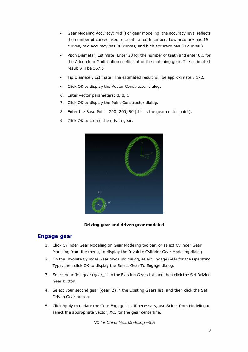
8. Enter the Base Point: 200, 200, 50 (this is the gear center point).
9. Click OK to create the driven gear.
Driving gear and driven gear modeled
Engage gear
1. Click Cylinder Gear Modeling on Gear Modeling toolbar, or select Cylinder Gear
Modeling from the menu, to display the Involute Cylinder Gear Modeling dialog.
2. On the Involute Cylinder Gear Modeling dialog, select Engage Gear for the Operating
Type, then click OK to display the Select Gear To Engage dialog.
3. Select your first gear (gear_1) in the Existing Gears list, and then click the Set Driving
Gear button.
4. Select your second gear (gear_2) in the Existing Gears list, and then click the Set
Driven Gear button.
5. Click Apply to update the Gear Engage list. If necessary, use Select from Modeling to
select the appropriate vector, XC, for the gear centerline.

NX for China GearModeling-8.5
9
6. Click OK to reposition gear_2 to engage with gear_1.
Driving gear and driven gear engaged

NX for China GearModeling-8.5
10
Example: Engaging Gears
This example lets you create three involute cylinder gears. You then use the Engage Gear,
Move Gear to relate gears.
Three Modeled and Engaged Cylinder Gears
Start Gear Modeling from the NX Application menu and select the type of gear you want to
create.
You can also pick the appropriate button on the Gear Modeling toolbar to create
gear.
Create three cylinder gears
The following text describes the processes you can use to create standard involute cylinder
gears.
Create a part
Begin by creating a part using File->New
For this example, select millimeter units.
Create gear 1
1. Click Cylinder Gear Modeling on Gear Modeling toolbar, or select Cylinder Gear
Modeling from the menu, to display the Involute Cylinder Gear Modeling dialog.
2. On the Involute Cylinder Gear Modeling dialog, select Create Gear as the Gear
Operating Type, then pick OK to display the Involute Cylinder Gear Type dialog.
NX for China GearModeling-8.5
11
3. On Involute Cylinder Gear Type dialog, select General Gear, Straight Gear, Internal
Gear, and Shaping for Machining, then click OK to display the Involute Cylinder Gear
Parameter dialog.
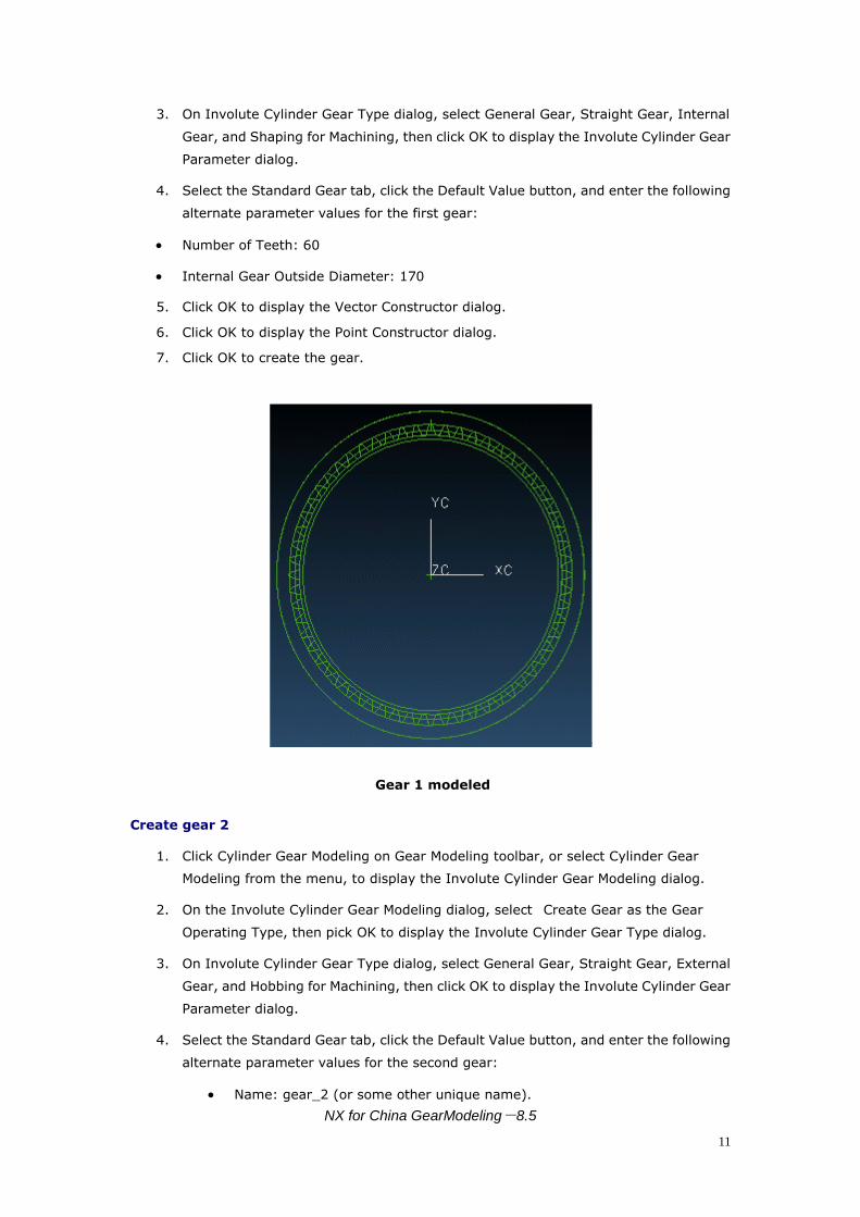
4. Select the Standard Gear tab, click the Default Value button, and enter the following
alternate parameter values for the first gear:
Number of Teeth: 60
Internal Gear Outside Diameter: 170
5. Click OK to display the Vector Constructor dialog.
6. Click OK to display the Point Constructor dialog.
7. Click OK to create the gear.
Gear 1 modeled
Create gear 2
1. Click Cylinder Gear Modeling on Gear Modeling toolbar, or select Cylinder Gear
Modeling from the menu, to display the Involute Cylinder Gear Modeling dialog.
2. On the Involute Cylinder Gear Modeling dialog, select Create Gear as the Gear
Operating Type, then pick OK to display the Involute Cylinder Gear Type dialog.
3. On Involute Cylinder Gear Type dialog, select General Gear, Straight Gear, External
Gear, and Hobbing for Machining, then click OK to display the Involute Cylinder Gear
Parameter dialog.
4. Select the Standard Gear tab, click the Default Value button, and enter the following
alternate parameter values for the second gear:
Name: gear_2 (or some other unique name).

NX for China GearModeling-8.5
12
Number of Teeth: 15.
5. Click OK to display the Vector Constructor dialog.
6. Click OK to display the Point Constructor dialog.
7. Enter the Base Point: 120, 0, 0.
8. Click OK to create the second gear.
Gears 1 and 2 modeled
Create gear 3
1. Click Cylinder Gear Modeling on Gear Modeling toolbar, or select Cylinder Gear
Modeling from the menu, to display the Involute Cylinder Gear Modeling dialog.
2. On the Involute Cylinder Gear Modeling dialog, select Create Gear as the Gear
Operating Type, then pick OK to display the Involute Cylinder Gear Type dialog.
3. On Involute Cylinder Gear Type dialog, select General Gear, Straight Gear, External
Gear, and Hobbing for Machining, then click OK to display the Involute Cylinder Gear
Parameter dialog.
4. Select the Standard Gear tab, click the Default Value button, and enter the following
alternate parameter values for the third gear:
Name: gear_3 (or some other unique name).
Number of Teeth: 30.
5. Click OK to display the Vector Constructor dialog.
6. Click OK to display the Point Constructor dialog.
7. Enter the Base Point: 200, 0, 0.
8. Click OK to create the third gear.

NX for China GearModeling-8.5
13
Gears 1, 2, and 3 modeled
Engage gear
1. Click Cylinder Gear Modeling on Gear Modeling toolbar, or select Cylinder Gear
Modeling from the menu, to display the Involute Cylinder Gear Modeling dialog.
2. On the Involute Cylinder Gear Modeling dialog, select Engage Gear for the Operating
Type, then pick OK to display the Select Gear To Engage dialog.
Create the first engaging relation
1. Select your first gear (gear_1) in the Existing Gears list, and then click the Set Driving
Gear button.
2. Click the Set Driven Gear button.
Select your second gear (gear_2) in the Existing Gears list.
Enter -1 for Center Line Vec JC.
Click Apply to create the first gear engaging relation and update the Gear Engaging
Relation List.
Create the second engaging relation
1. Select your second gear (gear_2) in the Existing Gears list, and then click the Set
Driving Gear button.
2. Click the Set Driven Gear button.
Select your second gear (gear_2) in the Existing Gears list.
Enter 1 for Center Line Vec JC.
Click Apply to create the second gear engaging relation.
3. Click OK update the Gear Engaging Relation List and engage the gear models.

NX for China GearModeling-8.5
14
Engaged gears
Move Gear
1. Click Cylinder Gear Modeling on Gear Modeling toolbar, or select Cylinder Gear
Modeling from the menu, to display the Involute Cylinder Gear Modeling dialog.
2. On the Involute Cylinder Gear Modeling dialog, select Move Gear for the Operating
Type, then pick OK to display the Select Gear To Operate dialog.
3. Select the first gear (gear_1), and then click OK to display the Gear Position dialog.
4. On the Gear Position dialog, specify the following parameter values:
Gear Origin: (100,0,0)
Gear Direction: (1,0,0)
5. Click OK to move the gear models.
Moved gear models

NX for China GearModeling-8.5
15
Display Gear Type
You can use the Display Gear dialog to list gear names and types.
To see the Display Gear dialog choose the following from the NX menu:Gear
Modeling->Display Gear Type.
Display Gear
The Display Gear dialog lists gear names and, in parentheses, gear type: cylinder gear, bevel
gear.
Click the Select from modeling button and enter a gear model name to jump to that name in
the list.

NX for China GearModeling-8.5
16
Cylinder Gear Modeling
Cylinder Gears External Straight External Helical Internal Straight Internal Helical
To start the cylinder gear modeling module, choose the following from the NX menu:
Tools->Gear Modeling->Cylinder Gear or click Cylinder Gear Modeling on the toolbar to
display the Involute Cylinder Gear Modeling dialog:
Cylinder Gear Modeling
The following process examples describe the options available with the cylinder gear
modeling module.
Create Gear
1. On the Involute Cylinder Gear Modeling dialog, select the Operating Type, which in
this case is Create Gear, then pick OK.
2. On the Involute Cylinder Gear Type dialog, select the General Gear type and
complete the dialog choices and click OK.
3. On the Involute Cylinder Gear Parameter input dialog, you can select the gear type
and provide required information or select default values, then click OK.
Gear Type

NX for China GearModeling-8.5
17
Standard Gear - addendum modification coefficient is zero, addendum factor is
standard value 1.0, clearance is standard value 0.25, and gear cutter top radius is
standard value 0.38m.
Addendum Modified Gear - addendum modification coefficient is not zero; addendum
factor, clearance, gear cutter top radius are not standard values.
Estimate: Pitch Diameter - lets you display another dialog to input Teeth Number and
Addendum Modification Coefficient parameters for the match gear. The software then
can estimate the Pitch Diameter of the gear.
Estimate: Tip Diameter - lets you display another dialog to input Teeth Number and
Addendum Modification Coefficient parameters for the match gear. The software then
can estimate the Tip Diameter of the gear.
Estimate: Addendum Modification Coe. - is used with English unit systems to you do
not know the Root Diameter parameter for the gear. You input Teeth Number and
Addendum Modification Coefficient parameters for the match gear. The software then
can estimate the Root Diameter of the gear.
Gear Modeling Accuracy - lets you select low, mid, or high accuracy.
Default Value - lets you use default cylinder gear parameters.
Available parameters will vary based on unit system, gear type, gear relation position,
and machining method.
4. On the Vector Constructor dialog, input the gear's center axis vector. You can select
an inferred vector, or input values for I, J, and K for either a Cartesian or spherical
coordinate system.
5. On the Point Constructor dialog, input the gear's center point. You can select an
inferred point or input values for XC, YC, and ZC for either WCS or Absolute location.
Edit Gear Parameters
1. On the Involute Cylinder Gear Modeling dialog, select Edit Gear Parameter.
2. On the Select Gear to Operate dialog, select the gear to edit from the list display.
Each selection displays the name of the gear model and the gear type: general gear.
3. On the Involute Cylinder Gear Type dialog, select the new gear type.
4. Use the Involute Cylinder Gear Parameter dialog to input the new gear parameters.
At this point you cannot input a Name. If the Remain the engaging relation toggle is
selected, the program will automatically move all engaged gears to the new position
and keep their engaging relation.
Engage Gear
1. On the Involute Cylinder Gear Modeling dialog, pick Engage Gear to establish the
engaging relation for your gears.
2. From the Gear Engaging Relation List on the Select Gear to engage dialog, pick the
created gear to engage.

NX for China GearModeling-8.5
18
Item Description.
Gear Engaging
Relation List
Display engaging relations to help you engage the gear.
If you click Set Driving Gear and select a gear in Existing Gears, the
same gear in this list will display '=>driving gear'.
Double click a node to expand the view.
Existing Gears
This dialog displays the names of all existing gears so you can select the
created gear to engage.
List items display both the name of gear model and the type of gear:
general gear.
If you do not click Set Driving Gear or Set Driven Gear, but you do click
Existing Gears, the software highlights only the gear model.
If you click Set Driving Gear, then click Existing Gears, the software
highlights the gear model and makes it a driving gear with the label
Driving Gear and the corresponding list item in Gear Engaging Relation
List displays '=>driving gear'.
Set Driving Gear Select the driving gear.
Set Driven Gear Select the driven gear.
Driving Gear The selected driving gear.
Driven Gear The selected driven gear.
Center Line Vector Invoke the standard vector dialog to input the center line vector of the
engaging gears from modeling.
Apply
Click Apply to only create the engaging relation of gear, and not update,
so you can create several engaging relations before performing the
update.
Ok Click OK to create the engaging relation of the gear and update the
model.
Move Gear
1. On the Involute Cylinder Gear Modeling dialog, pick Move Gear to translate and
rotate the created gear.
2. On the Select Gear to Operate dialog, select the created gear to move.
3. Use the Gear Position dialog to input the new gear position based on the selected
coordinate system.

NX for China GearModeling-8.5
19
The Remain the engaging relation toggle lets you automatically move all
engaged gears to the new position and keep their engaging relation.
Delete Gear
1. On the Involute Cylinder Gear Modeling dialog, pick Delete Gear to delete a created
gear.
2. On the Select Gear to Operate dialog, select the created gear to delete.
Information
1. On the Involute Cylinder Gear Modeling dialog, pick Information.
2. On the Select Gear To Operate dialog, note the gear names and types listed.

NX for China GearModeling-8.5
20
Bevel Gear Modeling
Bevel Gear Transmission Straight Bevel Gear Helical Bevel Gear
To start the bevel gear modeling module, choose the following from the NX menu:
Tools->Gear Modeling->Bevel Gear
Bevel Gear Modeling
The following options are available on the Bevel Gear Modeling dialog:
Create Gear: create the new gear.
Edit Gear Parameter: edit the created gear parameters and update.
Engage Gear: establish the engaging relation of gears.
Move Gear: translate and rotate the created gear.
Delete Gear: delete the created gear.
Information: display the created gear information.
Modeling a Bevel Gear
The following process examples describe the options available with the bevel gear modeling
module.
NX for China GearModeling-8.5
21
Create Gear
1. Select the Gear Operating Type, which in this case is Create Gear, and then pick OK.
2. Select the General Gear type on the Bevel Gear Type dialog, and then select the
appropriate options on the rest of the form.
Input Type: General Gear to manually input the gear parameters.
Gear Type: Straight or Helical
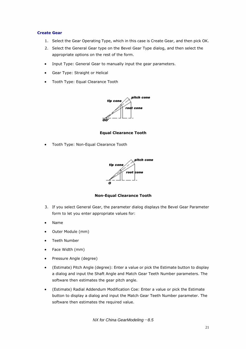
Tooth Type: Equal Clearance Tooth
Equal Clearance Tooth
Tooth Type: Non-Equal Clearance Tooth
Non-Equal Clearance Tooth
3. If you select General Gear, the parameter dialog displays the Bevel Gear Parameter
form to let you enter appropriate values for:
Name
Outer Module (mm)
Teeth Number
Face Width (mm)
Pressure Angle (degree)
(Estimate) Pitch Angle (degree): Enter a value or pick the Estimate button to display
a dialog and input the Shaft Angle and Match Gear Teeth Number parameters. The
software then estimates the gear pitch angle.
(Estimate) Radial Addendum Modification Coe: Enter a value or pick the Estimate
button to display a dialog and input the Match Gear Teeth Number parameter. The
software then estimates the required value.

NX for China GearModeling-8.5
22
(Estimate) Tangent Addendum Modification Coe: Enter a value or pick the Estimate
button to display a dialog and input the Match Gear Teeth Number parameter. The
software then estimates the required value.
(Estimate) Addendum Factor: Enter a value or pick the Estimate button to have the
software estimate the required value.
(Estimate) Clearance: Enter a value or pick the Estimate button to have the software
estimate the required value.
(Estimate) Gear Cutter Top Radius (mm): Enter a value or pick the Estimate button
to have the software estimate the required value.
Gear Modeling Accuracy (Low, Mid, High).
Default Value: Display the default bevel gear parameters.
The bevel gear parameters will vary based on the unit system and gear type.
4. On the Vector Constructor dialog you can select an Inferred Vector, input values I, J,
K for the gear's center axis vector, select Cartesian or Spherical coordinate systems,
and so on.
5. On the Point Constructor dialog, you can select an Inferred Point and input Base Point
coordinate values for XC, YC, and ZC for the crossing point of two gears' shaft.
Edit Gear Parameter:
1. On the Bevel Gear Modeling dialog, select Edit Gear Parameter.
2. On the Select Gear to Operate dialog, select the gear to edit from the list display.
Each selection displays the name of the gear model and the gear type: general gear.
3. On the Bevel Gear Type dialog, select the new gear type and tooth type.
4. Use the Bevel Gear Parameter dialog to input the new gear parameters and modeling
accuracy. At this point you cannot input a Name. See the Create Gear section for
additional information about particular parameters.
Engage Gear
1. On the Bevel Gear Modeling dialog, pick Engage Gear to establish the engaging
relation for your gears.
2. From the Gear Engaging Relation List on the Select Gear to Engage dialog, pick the
created gear to engage.
Item Description.
Gear Engaging
Relation List
Display engaging relations to help you engage the gear.
If you click Set Driving Gear and select a gear in Existing Gears, the
same gear in this list will display '=>driving gear'.
Double click a node to expand the view.
Existing Gears This dialog displays the names of all existing gears so you can select the

NX for China GearModeling-8.5
23
created gear to engage.
List items display both the name of gear model and the type of gear:
general gear.
If you do not click Set Driving Gear or Set Driven Gear, but you do click
Existing Gears, the software highlights only the gear model.
If you click Set Driving Gear, then click Existing Gears, the software
highlights the gear model and makes it a driving gear with the label
Driving Gear and the corresponding list item in Gear Engaging Relation
List displays '=>driving gear'.
Set Driving Gear Select the driving gear.
Set Driven Gear Select the driven gear.
Driving Gear The selected driving gear.
Driven Gear The selected driven gear.
Center Line Vector Invoke the standard vector dialog to input the center line vector of the
engaging gears from modeling.
Apply
Click Apply to only create the engaging relation of gear, and not update,
so you can create several engaging relations before performing the
update.
Ok Click OK to create the engaging relation of the gear and update the
model.
Move Gear
1. On the Bevel Gear Modeling dialog, pick Move Gear to translate and rotate the
created gear.
2. On the Select Gear to Operate dialog, select the general gear to move.
3. Use the Gear Position dialog to input the new gear position based on the selected
coordinate system.
The Remain the engaging relation toggle lets you automatically move all
engaged gears to the new position and keep their engaging relation.
Delete Gear
1. On the Bevel Gear Modeling dialog, pick Delete Gear to delete a created gear.
2. On the Select Gear to Operate dialog, select the created gear to delete.
Information
1. On the Bevel Gear Modeling dialog, pick Information.

NX for China GearModeling-8.5
24
2. On the Select Gear To Operate dialog, note the gear names and types listed.